JP6691616B2 - Rotor blade for wind power generator and wind power generator - Google Patents
Rotor blade for wind power generator and wind power generator Download PDFInfo
- Publication number
- JP6691616B2 JP6691616B2 JP2018557210A JP2018557210A JP6691616B2 JP 6691616 B2 JP6691616 B2 JP 6691616B2 JP 2018557210 A JP2018557210 A JP 2018557210A JP 2018557210 A JP2018557210 A JP 2018557210A JP 6691616 B2 JP6691616 B2 JP 6691616B2
- Authority
- JP
- Japan
- Prior art keywords
- region
- rotor blade
- hub
- rotor
- trailing edge
- Prior art date
- Legal status (The legal status is an assumption and is not a legal conclusion. Google has not performed a legal analysis and makes no representation as to the accuracy of the status listed.)
- Active
Links
- 238000000926 separation method Methods 0.000 claims description 17
- 230000007423 decrease Effects 0.000 claims description 11
- 230000007704 transition Effects 0.000 claims description 11
- 239000003381 stabilizer Substances 0.000 claims description 7
- 230000006835 compression Effects 0.000 claims description 3
- 238000007906 compression Methods 0.000 claims description 3
- 241000220317 Rosa Species 0.000 description 16
- 238000011161 development Methods 0.000 description 14
- 230000018109 developmental process Effects 0.000 description 14
- 230000015572 biosynthetic process Effects 0.000 description 5
- 238000004804 winding Methods 0.000 description 5
- 238000009826 distribution Methods 0.000 description 4
- 230000009467 reduction Effects 0.000 description 4
- 238000004519 manufacturing process Methods 0.000 description 3
- 230000004048 modification Effects 0.000 description 3
- 238000012986 modification Methods 0.000 description 3
- 238000010276 construction Methods 0.000 description 2
- 230000001419 dependent effect Effects 0.000 description 2
- 230000000694 effects Effects 0.000 description 2
- 230000000737 periodic effect Effects 0.000 description 2
- 229920000049 Carbon (fiber) Polymers 0.000 description 1
- 241000397426 Centroberyx lineatus Species 0.000 description 1
- 239000000654 additive Substances 0.000 description 1
- 230000000996 additive effect Effects 0.000 description 1
- 238000013459 approach Methods 0.000 description 1
- 230000009286 beneficial effect Effects 0.000 description 1
- 229960001716 benzalkonium Drugs 0.000 description 1
- CYDRXTMLKJDRQH-UHFFFAOYSA-N benzododecinium Chemical compound CCCCCCCCCCCC[N+](C)(C)CC1=CC=CC=C1 CYDRXTMLKJDRQH-UHFFFAOYSA-N 0.000 description 1
- 230000008859 change Effects 0.000 description 1
- 230000003247 decreasing effect Effects 0.000 description 1
- 230000003111 delayed effect Effects 0.000 description 1
- 238000013461 design Methods 0.000 description 1
- 238000010586 diagram Methods 0.000 description 1
- 239000000835 fiber Substances 0.000 description 1
- 239000011521 glass Substances 0.000 description 1
- 238000005339 levitation Methods 0.000 description 1
- 239000000463 material Substances 0.000 description 1
- 238000000034 method Methods 0.000 description 1
- 230000002093 peripheral effect Effects 0.000 description 1
- 230000008569 process Effects 0.000 description 1
- 230000004044 response Effects 0.000 description 1
- 238000004904 shortening Methods 0.000 description 1
- 238000000638 solvent extraction Methods 0.000 description 1
- 230000000087 stabilizing effect Effects 0.000 description 1
Images


Classifications
-
- F—MECHANICAL ENGINEERING; LIGHTING; HEATING; WEAPONS; BLASTING
- F03—MACHINES OR ENGINES FOR LIQUIDS; WIND, SPRING, OR WEIGHT MOTORS; PRODUCING MECHANICAL POWER OR A REACTIVE PROPULSIVE THRUST, NOT OTHERWISE PROVIDED FOR
- F03D—WIND MOTORS
- F03D1/00—Wind motors with rotation axis substantially parallel to the air flow entering the rotor
- F03D1/06—Rotors
- F03D1/0608—Rotors characterised by their aerodynamic shape
- F03D1/0633—Rotors characterised by their aerodynamic shape of the blades
- F03D1/0641—Rotors characterised by their aerodynamic shape of the blades of the section profile of the blades, i.e. aerofoil profile
-
- F—MECHANICAL ENGINEERING; LIGHTING; HEATING; WEAPONS; BLASTING
- F05—INDEXING SCHEMES RELATING TO ENGINES OR PUMPS IN VARIOUS SUBCLASSES OF CLASSES F01-F04
- F05B—INDEXING SCHEME RELATING TO WIND, SPRING, WEIGHT, INERTIA OR LIKE MOTORS, TO MACHINES OR ENGINES FOR LIQUIDS COVERED BY SUBCLASSES F03B, F03D AND F03G
- F05B2240/00—Components
- F05B2240/20—Rotors
- F05B2240/30—Characteristics of rotor blades, i.e. of any element transforming dynamic fluid energy to or from rotational energy and being attached to a rotor
- F05B2240/301—Cross-section characteristics
-
- F—MECHANICAL ENGINEERING; LIGHTING; HEATING; WEAPONS; BLASTING
- F05—INDEXING SCHEMES RELATING TO ENGINES OR PUMPS IN VARIOUS SUBCLASSES OF CLASSES F01-F04
- F05B—INDEXING SCHEME RELATING TO WIND, SPRING, WEIGHT, INERTIA OR LIKE MOTORS, TO MACHINES OR ENGINES FOR LIQUIDS COVERED BY SUBCLASSES F03B, F03D AND F03G
- F05B2240/00—Components
- F05B2240/20—Rotors
- F05B2240/30—Characteristics of rotor blades, i.e. of any element transforming dynamic fluid energy to or from rotational energy and being attached to a rotor
- F05B2240/302—Segmented or sectional blades
-
- F—MECHANICAL ENGINEERING; LIGHTING; HEATING; WEAPONS; BLASTING
- F05—INDEXING SCHEMES RELATING TO ENGINES OR PUMPS IN VARIOUS SUBCLASSES OF CLASSES F01-F04
- F05B—INDEXING SCHEME RELATING TO WIND, SPRING, WEIGHT, INERTIA OR LIKE MOTORS, TO MACHINES OR ENGINES FOR LIQUIDS COVERED BY SUBCLASSES F03B, F03D AND F03G
- F05B2260/00—Function
- F05B2260/96—Preventing, counteracting or reducing vibration or noise
-
- F—MECHANICAL ENGINEERING; LIGHTING; HEATING; WEAPONS; BLASTING
- F16—ENGINEERING ELEMENTS AND UNITS; GENERAL MEASURES FOR PRODUCING AND MAINTAINING EFFECTIVE FUNCTIONING OF MACHINES OR INSTALLATIONS; THERMAL INSULATION IN GENERAL
- F16C—SHAFTS; FLEXIBLE SHAFTS; ELEMENTS OR CRANKSHAFT MECHANISMS; ROTARY BODIES OTHER THAN GEARING ELEMENTS; BEARINGS
- F16C2360/00—Engines or pumps
- F16C2360/31—Wind motors
-
- Y—GENERAL TAGGING OF NEW TECHNOLOGICAL DEVELOPMENTS; GENERAL TAGGING OF CROSS-SECTIONAL TECHNOLOGIES SPANNING OVER SEVERAL SECTIONS OF THE IPC; TECHNICAL SUBJECTS COVERED BY FORMER USPC CROSS-REFERENCE ART COLLECTIONS [XRACs] AND DIGESTS
- Y02—TECHNOLOGIES OR APPLICATIONS FOR MITIGATION OR ADAPTATION AGAINST CLIMATE CHANGE
- Y02E—REDUCTION OF GREENHOUSE GAS [GHG] EMISSIONS, RELATED TO ENERGY GENERATION, TRANSMISSION OR DISTRIBUTION
- Y02E10/00—Energy generation through renewable energy sources
- Y02E10/70—Wind energy
- Y02E10/72—Wind turbines with rotation axis in wind direction
Description
本発明は、風力発電装置のロータブレード及び風力発電装置に関する。 The present invention relates to a rotor blade of a wind turbine generator and a wind turbine generator.
風力発電装置のロータのためのロータブレードは一般的に既知である。そのようなロータブレードは、特別な空気力学的要求を考慮する翼厚プロフィル(翼断面(翼弦方向の断面)プロフィル即ち輪郭形状)を有する。 Rotor blades for rotors of wind turbines are generally known. Such rotor blades have a blade thickness profile (blade cross-section profile) which allows for special aerodynamic requirements.
風力発電装置は例えば複数のロータブレードを有する空気力学的ロータを有するが、これは図1に例示されている。そのようなロータブレードの空気力学的特性は、ロータブレードの性能(可能出力)に、従って風力発電装置の性能(可能出力)に影響を及ぼす。ロータブレードの性能を向上するために、その翼厚プロフィルが最適化される。例えば風が弱い地域において、即ちとりわけ内陸部において、可及的に常時の電流(電力)生成を保証するためには、空気力学的ロータは、80mを超えることもあるロータ径を有する。そのような大型の風力発電装置では、従って、極めて大きなロータブレードでは、ロータブレードの質量は大きくなる。大型かつ重いロータブレードは、運転時に風力発電装置に作用する大きな負荷を生成する。更に、製造及び各建設地への輸送は複雑かつ困難である。ツーピース型の(2つの部分から構成される)ロータブレードの実現は、これはそのような大型のロータブレードの輸送のためにはより好都合であろうが、生成する負荷や付加的に分離箇所によって引き起こされる安定性低下のために、限定的にしか可能ではない。 A wind turbine generator has, for example, an aerodynamic rotor with a plurality of rotor blades, which is illustrated in FIG. The aerodynamic properties of such rotor blades affect the performance (capable output) of the rotor blades and thus the performance (capable output) of the wind turbine generator. The blade thickness profile is optimized to improve the performance of the rotor blade. In order to ensure as much as possible constant current (power) production, for example in windy areas, i.e. especially in the inland areas, aerodynamic rotors have a rotor diameter which can exceed 80 m. In such large wind turbines, and thus for very large rotor blades, the rotor blade mass is high. Large and heavy rotor blades generate a large load on the wind power plant during operation. Moreover, manufacturing and transportation to each construction site is complex and difficult. The realization of a two-piece rotor blade (composed of two parts), which would be more convenient for the transport of such large rotor blades, depends on the load generated and the additional separation points. Due to the stability loss caused, this is only possible on a limited basis.
とりわけハブ領域における、ロータブレードの翼厚プロフィルの形状は、例えばロータブレードの翼端領域におけるものとは異なるある種の要求が課されている。その概要は、例えばBarbara Souza-Heinzelmannの博士論文“Stroemungsbeeinflussung bei Rotorblaettern von Windenergieanlagen mit Schwerpunkt auf Grenzschichtabsaugung”(ベルリン、2011年6月23日)に記載されている。そこでは、空気力学的設計及びロータブレードの周囲の流れに対する種々の形の流れの影響が原理的に(基本的に)説明されている。とりわけ、この博士論文の図4−3は、ロータブレードを3つの領域即ちハブ領域、中央領域及び翼端領域に区分することを示している。流れの影響の対策は、例えば図5−7に示されている渦発生器ないしスポイラ或いは図5-8に示されている境界層フェンス(境界層板)で行い得る。 The shape of the blade thickness profile of the rotor blades, especially in the hub region, imposes certain requirements that differ from those in, for example, the tip region of the rotor blades. The outline is described, for example, in Barbara Souza-Heinzelmann's dissertation “Stroemungsbeeinflussung bei Rotorblaettern von Windenergieanlagen mit Schwerpunkt auf Grenzschichtabsaugung” (Berlin, June 23, 2011). There, in principle, the effects of different forms of flow on the aerodynamic design and the flow around the rotor blades are explained. Notably, Figure 4-3 of this dissertation illustrates partitioning a rotor blade into three regions: a hub region, a central region and a tip region. Countermeasures for the influence of the flow can be performed by, for example, the vortex generator or spoiler shown in FIG. 5-7 or the boundary layer fence (boundary layer plate) shown in FIGS. 5-8.
本出願人のロータブレードのハブ領域における翼厚プロフィルの傑出した形状は、その論文の図4−6において言及されている。例えばWO 2013/153 009からは、ロータブレードの翼弦長が増大するハブへのロータブレード接続部の付加物(Ansatz)が知られている。本出願人のDE 10 2013 210 901 A1には、例えば、この付加物と境界層フェンス等との組み合わせが開示されている。 The outstanding shape of the blade thickness profile in the hub region of Applicants' rotor blades is referred to in Figures 4-6 of that article. For example, from WO 2013/153009, an addition of a rotor blade connection to an hub (Ansatz) is known, which increases the chord length of the rotor blade. Applicant's DE 10 2013 210 901 A1 discloses, for example, a combination of this additive with a boundary layer fence or the like.
ロータブレード接続部の上記のものとは原理的に異なる1つの可能性は、ハブ領域における翼弦長の減少であるが、これにより、ロータブレードの中央領域における標準的翼厚プロフィルの形状から出発し、楕円(長円)形の翼断面(形状)を経由して、ハブ接続のためのほぼ円形の翼断面(形状)に変化する。これは、例えばDE 10 2008 052 858 B9に記載されているが、そのロータブレードは切頭後縁を有する。 One possibility, which is in principle different from the above of the rotor blade connection, is the reduction of the chord length in the hub region, which starts from the shape of the standard blade thickness profile in the central region of the rotor blades. Then, it changes to an almost circular blade cross section (shape) for hub connection via an elliptical (oval) blade cross section (shape). This is described, for example, in DE 10 2008 052 858 B9, whose rotor blades have a truncated trailing edge.
しかしながら、ロータブレード翼厚プロフィルの切頭後縁、いわゆるフラットバック(Flatback)翼厚プロフィルにおいて原理的に問題であるのは、原理的に依然として存在する制限された揚力特性を考慮したとしても、後縁に流れの剥離があることである。この問題の良好な概観は、例えばStandish et al. の文献“Aerodynamic Analysis of Blunt Trailing Edge Airfoils”, Journal of Solar Energy Engineering, vol. 125, p.479-486(2003年11月)に与えられている。 However, the problem in principle in the truncated trailing edge of the rotor blade thickness profile, the so-called Flatback blade thickness profile, is that even after considering the limited lift characteristics that still exist in principle, There is flow separation at the edges. A good overview of this problem is given, for example, in the article "Aerodynamic Analysis of Blunt Trailing Edge Airfoils" by Standish et al., Journal of Solar Energy Engineering, vol. 125, p.479-486 (November 2003). There is.
ドイツ特許商標庁は本願の優先権主張の基礎出願において以下の先行技術文献をサーチした:DE 10 2014 108917 A1、WO 2014/025252 A1、WO 2013/153009 A1、DE 10 2013 210901 A1、EP2 568 166 A1、DE 10 2014 206345 A1、DE 10 2008 052858 B9及びDE 10 2013 101232 A1。
The German Patent and Trademark Office searched the following prior art documents in the basic application for claiming priority of the present application:
それゆえ、本発明の課題は上記の問題の少なくとも1つを除去ないし軽減すること、とりわけ何れにせよハブ領域において制限された良好な揚力値を尚も有し、それにも拘らず、後縁渦発生の問題が軽減されるロータブレードを提供することである。とりわけ、ロータブレードは、ハブ領域において、選択的に増大する翼厚又は減少する翼厚を有するが、何れにせよ、ハブ領域におけるこの翼厚の部分において、比較的より簡単な輸送が可能となるよう構成されることが望まれる。 The object of the present invention is therefore to eliminate or mitigate at least one of the above-mentioned problems, in particular in any case still having a good lift value limited in the hub region, nevertheless nevertheless the trailing edge vortex. It is an object of the present invention to provide a rotor blade in which the problem of occurrence is reduced. In particular, the rotor blades have a selectively increasing or decreasing blade thickness in the hub region, but in any case a relatively simpler transport is possible in this portion of the blade thickness in the hub region. It is desirable to be configured as follows.
ロータブレードに関する課題は請求項1のロータブレードによって解決される。本発明は請求項34の風力発電装置も提供する。
即ち、本発明の一視点により、風力発電装置のための、吸引面と与圧面を有するロータブレードが提供される。該ロータブレードは、
・ロータブレードをロータハブに取り付けるためのハブ領域のロータブレード翼根部と、
・該ロータブレード翼根部の反対側の翼端領域に位置付けられたロータブレード翼端部と
を有し、
・前記ハブ領域の範囲において少なくとも部分的に、ロータブレードは、その後縁に棘状延長部を有する翼厚(翼断面)プロフィルを有し、
前記ハブ領域の範囲において少なくとも部分的に、前記翼厚プロフィルは、
・前記吸引面側の前記後縁の第1棘状延長部、及び、
・前記与圧面側の前記後縁の第2棘状延長部
を有し、
・前記ハブ領域において、前記後縁は平坦な又は湾曲した後縁であり、
・前記翼厚プロフィルは、前記吸引面側に前記後縁の第1棘状延長部を有しかつ前記与圧面側に前記後縁の第2棘状延長部を有し、該第1棘状延長部と該第2棘状延長部との間には平坦底部を有する谷部が形成されており、
・前記第1棘状延長部と前記第2棘状延長部との間の谷部の平坦底部は、前記ハブ領域のハブ近位領域においては、外部に向かって湾曲されており、かつ、前記ハブ領域のハブ遠位領域においては、内部に向かって湾曲されており、及び、
前記ハブ領域の範囲において少なくとも部分的に、前記翼厚プロフィルは、前記吸引面及び/又は前記与圧面上に、流れスタビライザ及び/又は渦発生器を有する(形態1・基本構成)。
更に、ロータを有する風力発電装置であって、該ロータが本発明に係るロータブレードを少なくとも1つ有する、風力発電装置も提供される(形態34)。
The problem with rotor blades is solved by the rotor blade of
That is, according to one aspect of the present invention, there is provided a rotor blade having a suction surface and a pressure surface for a wind turbine generator. The rotor blade is
A rotor blade blade root in the hub area for attaching the rotor blade to the rotor hub,
A rotor blade tip located in a tip area opposite the rotor blade root,
At least partially in the region of the hub region, the rotor blades have a blade thickness (wing cross-section) profile with a barbed extension at the trailing edge,
At least in part in the region of the hub region, the airfoil thickness profile is
A first barbed extension of the trailing edge on the side of the suction surface, and
-Has a second barbed extension of the trailing edge on the pressure surface side,
-In the hub region, the trailing edge is a flat or curved trailing edge,
The wing thickness profile has a first barbed extension of the trailing edge on the suction side and a second barb extension of the trailing edge on the pressure side, A valley having a flat bottom is formed between the extension and the second barb-like extension,
The flat bottom of the valley between the first barb-like extension and the second barb-like extension is curved outward in the hub proximal region of the hub region, and In the hub distal region of the hub region, curved inward, and
At least partly in the region of the hub region, the airfoil thickness profile has a flow stabilizer and / or a vortex generator on the suction surface and / or the pressure surface (
Further provided is a wind turbine generator having a rotor, the rotor having at least one rotor blade according to the present invention (mode 34).
WO 2014/025 252 A1は、本願の優先日前に出願されかつその後公開されており、従って、本願の新規性に関してのみ関連性がある―WO 2014/025 252 A1は、空気力学的プロフィル(翼厚プロフィル)であって、該空気力学的プロフィルの後縁に非対称的で、内部側への陥入形状で(内部陥入状:eingestuelpt)、尾状の谷状体(燕尾状(swallow tail shaped-schwalbenschwanzartig))を有するものを記載しているが、これは例えば風力タービンのために使用可能である。この非対称的内部陥入状尾状谷状体は第1部分と第2部分とを有し、これらの間に谷部(キャビティ)が形成されている。第1及び第2部分は、夫々、(断面において)直線的な上側及び下側外周面を有し、これらは相応に空気力学的プロフィルの上面及び下面に面一に整列している。 WO 2014/025 252 A1 was filed and published before the priority date of the present application and is therefore only relevant with respect to the novelty of the present application-WO 2014/025 252 A1 has an aerodynamic profile (wing thickness Profile), which is asymmetrical to the trailing edge of the aerodynamic profile and has an inward inward shape (eingestuelpt) with a caudal valley (swallow tail shaped- schwalbenschwanzartig)), which can be used, for example, for wind turbines. The asymmetric invaginated caudal trough has a first portion and a second portion with a trough (cavity) formed therebetween. The first and second parts each have a straight (in cross section) upper and lower peripheral surface, which are correspondingly flush-aligned with the upper and lower surfaces of the aerodynamic profile.
本発明は、風力発電装置の常に発展し続ける過程において、より多くのエネルギを風から取り出すことができるよう、ロータ径が増大していくという考察を出発点としている。しかしながら、空気力学的及び構造力学的自然法則のために、ロータブレードの長さのみを拡大すること、例えば幅ないし翼弦長を維持することは、不可能であるか、ないしは、限定的にのみ可能である。なぜなら、このために、更なる空気力学的補助手段がなしで、空気力学的プロフィルの周囲の使用領域(Einsatzbereich)にきれいな流れの状態を設定(形成)することができないからである。かくして、ロータ面が益々拡大することにより、風力発電装置全体の音響放出(騒音)レベルに増大するが、これも考慮する必要がある。 The present invention has as a starting point the consideration that the rotor diameter increases so that more energy can be taken out from the wind in the constantly developing process of the wind turbine generator. However, due to the natural laws of aerodynamics and structural mechanics, it is not possible, or only limited, to extend the length of the rotor blades, for example to maintain the width or chord length. It is possible. This is because, because of this, it is not possible to set (form) a clean flow condition in the area of use (Einsatzbereich) around the aerodynamic profile without further aerodynamic aids. Thus, the further expansion of the rotor surface increases the acoustic emission (noise) level of the entire wind turbine, which also needs to be considered.
本発明は、基本的に、翼端領域及び中央領域に標準的な空気力学的プロフィル(翼厚プロフィル)を有するロータブレードを、空気力学的翼厚プロフィル―とりわけハブ領域に、とりわけ切頭後縁を有するフラットバックプロフィル―を有するロータブレードとして形成することが有利であることを認識した。これにより、翼弦長の縮小が可能になる一方で、揚力挙動(特性)を維持することができる。 The invention basically provides a rotor blade having a standard aerodynamic profile (blade thickness profile) in the tip and central regions, in particular in the aerodynamic thickness profile-specifically in the hub region, especially on the truncated trailing edge. It has been found to be advantageous to form it as a rotor blade having a flat back profile with. As a result, the chord length can be reduced, while the lift behavior (characteristics) can be maintained.
本発明は、この考察から出発し―即ちWO 2013/153 009 A1に記載されているような相応に翼厚が更に増大する(但し必須ではない)という本出願人のコンセプトから出発し、ハブ領域の範囲において少なくとも部分的に、その後縁に棘状延長部を有する翼厚プロフィル(を有するもの)としてロータブレードを構成すると、基本的に更に有利であることを認識した。後縁は、とりわけこの認識に応じ、寧ろ平坦後縁として理解すべきものであり、そして、これに対して(翼断面で見て)棘状延長部が考察される。この場合、実際の、その限りで尖頭状の、後縁は棘状延長部の末端に形成されている。 The present invention starts from this consideration-that is to say from the Applicant's concept that the blade thickness is correspondingly (but not necessarily) increased as described in WO 2013/153 009 A1, the hub region. It has been recognized that it is basically more advantageous to configure the rotor blade as a blade profile with (at least) in the range of, at least partially, a trailing edge at the trailing edge. The trailing edge is to be understood as a rather flat trailing edge, in particular in response to this recognition, and for this the barbed extension (in wing cross section) is considered. In this case, the actual, most pointed, trailing edge is formed at the end of the spinous extension.
そのような棘状延長部に基づいて、ハブ領域の翼弦長が有利に短く構成(設計)可能であるだけではなく、更には、渦の剥離も、従って音響放出も有利に(即ち抑制した状態で)設計可能である。 Based on such a barbed extension, not only can the chord length of the hub region be advantageously designed (designed) to be short, but also vortex shedding and thus acoustic emission can be advantageously (ie suppressed). It can be designed.
ハブ領域の範囲において少なくとも部分的にロータブレードが翼厚プロフィルを有し、該翼厚プロフィルが吸引面側の後縁の第1棘状延長部と与圧面側の後縁の第2棘状延長部とを有すると有利であることが本発明によって判明した。 At least partially in the region of the hub region, the rotor blades have a blade thickness profile, the blade thickness profile being a first barb-like extension on the suction side trailing edge and a second barb-like extension on the pressure side. It has been found according to the invention that it is advantageous to have parts.
本発明のそのような及び他の有利な発展形態は、従属請求項から見て取ることが可能であり、上述のコンセプトを設定課題の枠内において及び更なる利点に関して実現する有利な可能性を各別に提供する。 Such and other advantageous developments of the invention can be taken from the dependent claims, which in each case have advantageous possibilities of realizing the above-mentioned concept within the framework of the setting problem and with regard to further advantages. provide.
ハブ領域の範囲において、翼厚プロフィルは、有利には、フラットバック翼厚プロフィルとして構成されている、即ち、切頭後縁を備えて構成されている。ハブ領域においては、後縁は、有利には、所定の相対翼厚を有する、とりわけ5%より大きい相対翼厚を有する平坦(フラット)後縁である。 In the region of the hub region, the airfoil thickness profile is preferably configured as a flatback airfoil thickness profile, i.e. with a truncated trailing edge. In the hub region, the trailing edge is advantageously a flat trailing edge with a predetermined relative blade thickness, in particular with a relative blade thickness greater than 5%.
翼厚プロフィルは、有利には、40%より大きい、とりわけ45%より大きい相対翼厚を有する。後縁から測定される相対棘長さは、有利には、25%未満であり及び/又は少なくとも後縁の所定の相対翼厚より大きく、とりわけ5%より大きい。ここで、再びとりわけ本発明の理解に応じ、(後縁は)寧ろ平坦後縁として理解可能であり、これに対して相対翼厚及び棘状延長部が考察される。 The blade thickness profile advantageously has a relative blade thickness of greater than 40%, especially greater than 45%. The relative barb length measured from the trailing edge is advantageously less than 25% and / or at least greater than a predetermined relative wing thickness at the trailing edge, in particular greater than 5%. Here again, in particular according to the understanding of the invention, the trailing edge can be understood as a rather flat trailing edge, for which the relative wing thickness and the barbed extension are considered.
薔薇棘状翼厚プロフィルとも称されるそのような翼断面プロフィルは、フラットバック翼厚プロフィルの上記の発展形態に応じた1つの修正に相当し、この場合、本発明の有利な一発展形態に相当する。 Such an airfoil cross-section profile, also referred to as a rose thorn-shaped airfoil profile, represents a modification of the flatback airfoil thickness profile described above, in which case it represents an advantageous development of the invention. Equivalent to.
原理的に、本発明のコンセプトに応じて、翼弦長ないしはロータブレード翼幅の更なる短縮が達成可能である。翼厚プロフィルは、有利には、50%より大きい、とりわけ75%より大きい相対翼厚を有する。 In principle, further shortening of the chord length or rotor blade span is achievable in accordance with the inventive concept. The blade thickness profile advantageously has a relative blade thickness of greater than 50%, especially greater than 75%.
棘状延長部の好ましくは複式に−即ち吸引面側及び与圧面側において−薄く延出する末端縁部分によって、音響放出はフラットバック翼厚プロフィルと比べて低減される。 The acoustic emission is reduced compared to the flat-back airfoil thickness profile by the preferably double-extending, thin-extending end edge portions of the barbs, ie on the suction side and the pressure side.
後縁棘状部(棘状延長部)の特別な形状によって、制御可能な後縁渦発生を達成することができる。即ち、とりわけ吸引面側及び与圧面側に設けられた複式構成の棘状部(棘状延長部)の場合、吸引面側棘状部と与圧面側棘状部の間の谷部(溝部ないし凹部)において(何れにせよ1つの棘状部の上方又は下方において)渦を安定化することができ、それにも拘らず、翼厚プロフィルはハブ領域の範囲において比較的良好な揚力値を有することが分った。有利なことに、流れが乱流的である場合ないし風が種々に変化する場合であっても、谷部における又は1つの棘状部の下方又は上方における渦の、パルス的又は周期的なものであっても、安定的な形成が可能であることが分った。谷部における又は1つの棘状部の下方又は上方における渦の、パルス的又は周期的なものであっても、安定的な形成によって、有効翼弦長は増大され、かくして、翼厚プロフィルの揚力(浮揚)挙動(特性)は改善される。 Due to the special shape of the trailing barbs (barb extensions), controllable trailing edge vortex generation can be achieved. That is, in particular, in the case of a double-structured barbed (barbed extension) provided on the suction surface side and the pressurizing surface side, a valley (a groove or The vortex can be stabilized in the recess) (either above or below one barb in any case) and the airfoil profile nevertheless has a relatively good lift value in the region of the hub region. I understood. Advantageously, pulsed or periodic vortices in the valleys or below or above one barb, even if the flow is turbulent or the wind varies. Even, it was found that stable formation is possible. The stable chord formation, whether pulsed or periodic, of the vortex in the valley or below or above one barb increases the effective chord length, thus increasing the lift of the blade thickness profile. The (levitation) behavior (characteristics) is improved.
有利には、後縁において測定される相対棘長さは25%未満であり及び/又は少なくとも後縁の所定の相対翼厚より大きく、とりわけ5%より大きく、有利には、最大相対棘長さは15%〜25%である。ここで、再びとりわけ本発明の理解に応じ、(後縁は)寧ろ平坦後縁として理解すべきであり、これに対して相対翼厚及び棘状延長部の相対棘長さが考察される。 Advantageously, the relative barb length measured at the trailing edge is less than 25% and / or at least greater than a predetermined relative blade thickness at the trailing edge, in particular greater than 5%, and advantageously the maximum relative barb length. Is 15% to 25%. Here again, in particular according to the understanding of the invention, the trailing edge should be understood as a rather flat trailing edge, for which the relative wing thickness and the relative barb length of the barb extension are considered.
有利には、ハブ領域の範囲において少なくとも部分的に、(ブレード長軸方向に関し)後縁は(吸引面側から見て)鋸歯形状(Serrationsform)を有する、即ちいわゆるギザギザ(鋸歯状)後縁として構成されている。ギザギザ後縁は、吸引面側(上)に及び/又は与圧面側に、或いは与圧及び/又は吸引面側のみに又は後縁の平坦な推移全体にわたって形成可能である。ここで、再びとりわけ本発明の理解に応じ、(後縁は)(翼断面プロフィルで見て)寧ろ平坦後縁として、場合によっては棘状延長部の尖頭状後縁としても、理解すべきものであり、これに対して(吸引面側から見て)ギザギザ後縁が考察される。即ち、とりわけ、鋸歯形状が棘状延長部の末端部に設けられる。 Advantageously, at least partly in the region of the hub region, the trailing edge (with respect to the blade longitudinal direction) has a serrations form (as viewed from the suction side), ie as a so-called serrated trailing edge. It is configured. The notched trailing edge can be formed on the suction side (top) and / or on the pressure side, or only on the pressure and / or suction side or over the entire flat transition of the trailing edge. Here again, in particular in accordance with the understanding of the invention, the trailing edge (as viewed in the wing profile) should be understood as a flat trailing edge rather than a flat trailing edge of the spinous extension in some cases. Against this, the jagged trailing edge (as viewed from the suction side) is considered. That is, inter alia, a sawtooth shape is provided at the distal end of the barb extension.
ハブ領域の範囲において少なくとも部分的に翼厚プロフィル(翼型)が吸引面及び/又は与圧面上に流れスラビライザ(Stroemungsstabilisator)を有する本発明の一発展形態は有利であることが判明した。とりわけ、流れスタビライザ(安定器)は、スポイラ、境界層フェンス、境界層吸引部(Grenzschichtabsaugung)からなる群から選択可能である。 One development of the invention has proved to be advantageous in that in the region of the hub region the airfoil profile has a flow stroemizer (Stroemungsstabilisator) on the suction surface and / or the pressure surface, at least in part. In particular, the flow stabilizer can be selected from the group consisting of spoilers, boundary layer fences, boundary layer suctions (Grenzschichtabsaugung).
付加的に又は代替的に、ハブ領域の範囲において少なくとも部分的に翼厚プロフィルが吸引面及び/又は与圧面上に渦発生器(ジェネレータ)を有する本発明の一発展形態も有利であることが判明した。とりわけ、渦発生器は、フィン(Finne)、スタッド(Noppe)、ディンプル(Dimpel)、ウェブ(Steg)又はそのようなタービュレータ(Turbulatoren)、噴出(Ausblas)又は吸引(Absaug)構造体からなる群から選択される。渦発生器によって、境界層厚は、乱流的な流れの場合、増大されることができる、即ち、層流的な流れの場合よりもより大きい。尤も、流速(流れの速さ)は距離が大きくなるにつれて層流の場合よりもより迅速に増大するため、流れのエネルギはより大きくなるが、より大きなエネルギは、流れを、ロータブレード面からの剥離に対する抵抗力をより大きくする。渦発生器又はそのようなタービュレータは、一般的に、人工的に設けられた小さな表面障害物である。これらは渦流(Verwirbelungen)を生成し、層流的な境界層流れを乱流的な流れに変換する。流れの剥離は遅延される。タービュレータは、例えば、横方向に延在するレール状部材、垂直小板又は(垂直小)孔を含む。境界層流れを激変させる更なる可能性は、噴出(Ausblas)又は吸引(Absaug)タービュレータである。これは一連の微細孔から構成され、空気は、これらを介して、流れの方向に対し横方向に、境界層内へ噴出されるか又は吸引される。 Additionally or alternatively, a development of the invention in which the airfoil thickness profile at least partially in the region of the hub region has a vortex generator on the suction surface and / or the pressure surface may also be advantageous. found. Among other things, the vortex generator is of the group consisting of Finne, Noppe, Dimpel, Web (Steg) or such Turbulators, Ausblas or Absaug structures. To be selected. Due to the vortex generator, the boundary layer thickness can be increased in the case of turbulent flow, i.e. greater than in the case of laminar flow. However, since the flow velocity (flow velocity) increases more rapidly with increasing distance than in the case of laminar flow, the energy of the flow is greater, but the greater energy causes the flow to flow from the rotor blade surface. Greater resistance to peeling. Vortex generators or such turbulators are generally small artificially constructed surface obstacles. These generate vortices (Verwirbelungen) and convert laminar boundary layer flow into turbulent flow. Flow separation is delayed. Turbulators include, for example, laterally extending rail-like members, vertical platelets or (vertical small) holes. A further possibility of disrupting boundary layer flow is the blast (Ausblas) or suction (Absaug) turbulators. It consists of a series of micropores through which air is jetted or sucked transversely to the direction of flow into the boundary layer.
第1領域において、即ち第1ハブ近位領域において、翼厚プロフィルはその後縁に棘状延長部を有し、及び、第2領域において、即ち第2ハブ遠位領域において、翼厚プロフィルの後縁は、棘状延長部を有しない平坦後縁であることは、特に好ましい一発展形態の枠内にある。 In the first region, i.e. in the first hub proximal region, the airfoil thickness profile has a barbed extension at its trailing edge, and in the second region, i.e. in the second hub distal region, after the airfoil thickness profile. It is within the framework of a particularly preferred development that the edge is a flat trailing edge without barb extensions.
ロータブレードの翼根(部)と翼端(部)の間にある局所的最大というコンセプトは、本発明の棘状延長部と特に有利に組み合わせることができる。好ましくは、ハブ領域の、第1領域、とりわけハブ領域のハブ近位領域と、第2領域、とりわけハブ領域のハブ遠位領域との間において、翼厚プロフィルは最大翼弦長を有する。 The concept of local maxima between the root and tip of the rotor blades can be combined particularly advantageously with the barb extension of the invention. Preferably, the airfoil profile has a maximum chord length between the first region, in particular the hub proximal region of the hub region, and the second region, in particular the hub distal region of the hub region, of the hub region.
好ましくは、翼弦長に対する翼厚の比として定義される相対翼厚は、ハブ領域のロータブレード翼根部と翼端領域のロータブレード翼端部の間の領域、好ましくは中央領域に、局所的最大を有する。 Preferably, the relative blade thickness, defined as the ratio of the blade thickness to the chord length, is localized in the region between the rotor blade root of the hub region and the rotor blade tip of the tip region, preferably in the central region. Have a maximum.
好ましくは、局所的最大の相対翼厚は35%〜50%であり及び/又はロータブレードは局所的最大の範囲に1500mm〜3500mmの翼弦長を有する。 Preferably, the local maximum relative blade thickness is 35% to 50% and / or the rotor blades have a chord length in the local maximum range of 1500 mm to 3500 mm.
好ましくは、ロータブレードは第1ロータブレード部分と第2ロータブレード部分とから構成されており、第1ロータブレード部分はロータブレード翼根部を有し、第2ロータブレード部分はロータブレード翼端部を有し、及び、第1及び第2ロータブレード部分は分離箇所において互いに結合されている。好ましくは、分離箇所は、ロータブレード翼根部とロータブレード翼端部との間の中央領域に及び/又は局所的最大の領域に配されている。 Preferably, the rotor blade comprises a first rotor blade portion and a second rotor blade portion, the first rotor blade portion having a rotor blade root portion and the second rotor blade portion having a rotor blade tip portion. And the first and second rotor blade portions are joined together at a separation point. Preferably, the separation point is located in the central region between the rotor blade root and the rotor blade tip and / or in the region of local maximum.
上記の各発展形態は、以下に示すような絶対寸法を有するロータブレードにおいて具現化されると、特に有利であることが判明した。 Each of the above developments has proved to be particularly advantageous when embodied in a rotor blade having absolute dimensions as shown below.
好ましくは、ロータブレードは、第1領域、とりわけハブ領域のハブ近位領域に、少なくとも3900mmの絶対翼弦長、とりわけ4000mm〜8000mmの範囲の絶対翼弦長を有する。 Preferably, the rotor blades have an absolute chord length in the first region, in particular in the hub proximal region of the hub region, of at least 3900 mm, in particular in the range 4000 mm to 8000 mm.
これらの絶対翼弦長は、棘状延長部を有しないが比肩する揚力値を有する他のロータブレードの場合よりも、15%〜30%だけより短い。 These absolute chord lengths are 15% to 30% shorter than for other rotor blades without spine extensions but with comparable lift values.
好ましくは、ロータブレードは、ロータブレード翼根部から出発してその全長の90%〜95%の範囲に、最大で1000mmの絶対翼弦長、とりわけ400mm〜700mmの範囲の絶対翼弦長を有する。 Preferably, the rotor blade has an absolute chord length of up to 1000 mm, in particular in the range of 400 mm to 700 mm, starting from the root of the rotor blade and ranging from 90% to 95% of its total length.
これらの絶対翼弦長も、棘状延長部を有しないが比肩する揚力値を有する他のロータブレードの場合よりも、15%〜30%だけより短い。 These absolute chord lengths are also 15% to 30% shorter than for other rotor blades without spine extensions but with comparable lift values.
好ましくは、ロータブレードは、中央領域に、ハブ領域における翼弦長の凡そ20%〜30%に、とりわけ凡そ25%に相当する翼弦長を有する。 Preferably, the rotor blades have a chord length in the central region which corresponds to approximately 20% to 30%, in particular approximately 25% of the chord length in the hub region.
更なる一発展形態の枠内において、
・ハブ領域の、第1領域、とりわけハブ領域のハブ近位領域において、翼厚プロフィルは、その平坦後縁に、第1相対翼厚と棘状延長部を有し、
・ハブ領域の、第2領域、とりわけハブ領域のハブ遠位領域において、翼厚プロフィルの後縁は、棘状延長部を有しない尖頭状後縁、又は、より小さい第2相対翼厚と、同じく棘状延長部を有する平坦後縁を有する、
ことが可能である。
Within the framework of a further development,
-In the hub region, in the first region, in particular in the hub proximal region of the hub region, the airfoil profile has at its flat trailing edge a first relative airfoil thickness and a barbed extension,
-In the hub region, in the second region, in particular in the hub distal region of the hub region, the trailing edge of the blade thickness profile has a pointed trailing edge without barb extensions or a smaller second relative blade thickness. , Also having a flat trailing edge with spinous extensions,
It is possible.
本発明のそのような及び他の更なる有利な発展形態は、更なる従属請求項に見て取ることが可能であり、上述のコンセプトを設定課題の枠内において及び更なる利点に関して実現する有利な可能性を各別に提供する。 Such and other further advantageous developments of the invention can be found in the further dependent claims and are advantageous possibilities of implementing the above concept within the framework of the setting task and with regard to further advantages. Gender is provided separately.
翼厚プロフィルは、有利には、50%より大きい、とりわけ75%より大きい相対翼厚を有する。好ましくは、ロータブレードのために、翼厚プロフィル(翼型)は、実質的に楕円形、卵形又は円筒形のコア(ないし本体:Kern)の形で形成されている。とりわけ理想的ないし卵形の楕円の場合については、翼厚プロフィルは、有利には、50%より大きい、とりわけ75%より大きい相対翼厚を有する。好ましくは、コアは、ハブ結合部に向かって次第に円筒形状になる、即ち、ロータブレードは、100%までの(100%に近い)相対翼厚を有する翼厚プロフィル(翼型)を有する。 The blade thickness profile advantageously has a relative blade thickness of greater than 50%, especially greater than 75%. Preferably, for the rotor blades, the airfoil profile is formed in the form of a substantially elliptical, oval or cylindrical core (or body: Kern). Particularly in the case of ideal to oval ellipses, the blade thickness profile advantageously has a relative blade thickness of greater than 50%, in particular greater than 75%. Preferably, the core is gradually cylindrical towards the hub connection, ie the rotor blades have a blade thickness profile (airfoil) with a relative blade thickness of up to 100% (close to 100%).
特に有利には、コアは、75%より大きい相対翼厚のところで、巻回体(Wickelteil)として形成されている。とりわけ、そのために、コアは、(例えばガラス又は炭素)繊維強化(GFK)プロフィルとして形成されている。そのために、例えば、フィラメント又はマット又はそのようなファイバが心棒に巻きつけられ、その後、この心棒が除去されることにより、コアが後に残った巻回体、とりわけGFK巻回体として得られる。 Particularly advantageously, the core is formed as a Wickelteil with a relative blade thickness of greater than 75%. Among other things, for that purpose, the core is formed as a (eg glass or carbon) fiber reinforced (GFK) profile. To that end, for example, a filament or mat or such a fiber is wrapped around a mandrel, which is then removed, so that the core is obtained as a wound body, in particular a GFK wound body.
ロータブレードはハブ領域において特に効率的に製造可能であるが、このためには、50%より大きい、とりわけ75%より大きい相対翼厚を有する上記の翼厚プロフィル(翼型)としてのコアに関し、所定の相対後縁厚みを有するその後縁に、棘状延長部が設けられる、とりわけ棘状延長部のみが設けられる。50%より大きい、とりわけ75%より大きい有利な相対翼厚を有する翼厚プロフィルと棘状延長部とを有する実質的に円筒形又は卵形の巻回体は、この意味で、特に好ましい実施形態として図12に示されている。 Rotor blades can be manufactured particularly efficiently in the hub region, for which purpose a core as an airfoil profile as described above having a relative blade thickness of greater than 50%, in particular greater than 75%, At the trailing edge with a predetermined relative trailing edge thickness, there are barbed extensions, in particular only barbed extensions. Substantially cylindrical or oval windings with a blade thickness profile and a barbed extension having an advantageous relative blade thickness of greater than 50%, in particular greater than 75%, are particularly preferred embodiments in this sense. Is shown in FIG.
円筒形又は卵形のコア、好ましくは実質的に円筒形又は卵形の巻回体は、吸引面側の後縁の第1棘状延長部と与圧面側の後縁の第2棘状延長部とを有し、第1棘状延長部と第2棘状延長部の間に平坦底部を有する谷部が形成されている。とりわけ、翼弦長に対する翼厚の比として定義される相対翼厚及び/又は絶対翼厚は、ロータブレード翼根部からロータブレード翼端部に向かって減少することが望ましい。 A cylindrical or oval core, preferably a substantially cylindrical or oval winding, has a first barb-like extension on the suction side trailing edge and a second barb-like extension on the pressure side. And a trough having a flat bottom is formed between the first barb-like extension and the second barb-like extension. In particular, it is desirable that the relative blade thickness and / or the absolute blade thickness, which is defined as the ratio of the blade thickness to the chord length, decrease from the rotor blade blade root toward the rotor blade blade tip.
好ましくは、第1棘状延長部と第2棘状延長部との間の谷部の平坦底部は、何れにせよハブ領域のハブ近位領域において、(ロータブレードの)外部に向かって湾曲されている。好ましくは、第1棘状延長部と第2棘状延長部との間の谷部の平坦底部は、何れにせよハブ領域のハブ遠位領域において、(ロータブレードの)内部に向かって湾曲されている。 Preferably, the flat bottom of the trough between the first barb extension and the second barb extension is curved towards the outside (of the rotor blade) in the hub proximal region of the hub region anyway. ing. Preferably, the flat bottom of the valley between the first barb and the second barb extends inwardly (in the rotor blade) in the hub distal region of the hub region. ing.
ロータブレードにおいて、特に好ましくは、後縁の第1棘状延長部と第2棘状延長部は、60°未満の円周角で配置されており、該円周角は、迎角を有しない(迎角が0°の)翼厚プロフィル軸を基準として、従って水平を基準として測定される。 In the rotor blade, particularly preferably, the first and second barb extensions of the trailing edge are arranged at a circumferential angle of less than 60 °, the circumferential angles having no elevation angle. It is measured relative to the wing thickness profile axis (with an angle of attack of 0 °) and thus to the horizontal.
特に好ましい一発展形態の枠内では、ハブ領域において、とりわけハブ領域のハブ近位領域において、吸引面側の後縁の第1棘状延長部は、与圧面側の後縁の第2棘状延長部の相対棘長さより短い相対棘長さを有する。 Within the framework of a particularly preferred development, in the hub region, in particular in the hub proximal region of the hub region, the first barb-shaped extension on the suction-side trailing edge is the second barb-shaped on the pressure-side trailing edge. It has a relative barb length that is shorter than the relative barb length of the extension.
特に好ましい一発展形態の枠内では、ハブ領域において、とりわけハブ領域のハブ近位領域において、与圧面側の後縁の第2棘状延長部は、吸引面側の後縁の第1棘状延長部の配向(Ausrichtung)よりもより大きく与圧面に向かって傾けられている配向を有する。 Within the framework of a particularly preferred development, in the hub region, in particular in the hub proximal region of the hub region, the second barb-shaped extension on the trailing edge on the pressure side comprises the first barb on the trailing edge on the suction side. It has an orientation that is more tilted towards the pressure surface than the extension orientation (Ausrichtung).
特に好ましい更なる一発展形態の枠内では、ハブ領域において、吸引面側の後縁の第1棘状延長部は、円周角が実質的に一定のままで、翼端領域の方向に延在し、かつ、与圧面側の後縁の第2棘状延長部は、円周角が実質的に減少しつつ、翼端領域の方向に延在している。換言すれば、例えば、円周角が実質的に一定である吸引面側の棘状延長部は、(時計の)1時位置と3時位置の間の実質的に一定の位置、例えばほぼ2時位置に配されており、与圧面側の棘状延長部は、例えば、5時位置と3時位置の間のある位置に配されており、好ましくは、翼端領域の方向に向かって5時位置から3時位置までその位置が徐々に減少するよう延在する。 In a frame of a further particularly preferred further development, in the hub region, the first barb-like extension of the suction surface side trailing edge extends in the direction of the wing tip region while the circumferential angle remains substantially constant. The second barb-like extension, which is present and at the trailing edge on the pressure-applying surface side, extends in the direction of the wing tip region while the circumferential angle is substantially reduced. In other words, for example, the barb-like extension on the suction side, which has a substantially constant circumferential angle, can be located at a substantially constant position between the 1 o'clock and 3 o'clock positions (of the clock, for example approximately 2). The barb-like extension on the pressurizing surface side is arranged at a certain position, for example, between the 5 o'clock position and the 3 o'clock position, and is preferably 5 in the direction of the wing tip region. The position extends gradually from the hour position to the three o'clock position.
好ましくは、ハブ領域において、後縁の第1棘状延長部と後縁の第2棘状延長部は合流する、とりわけ0°の円周角又はマイナスの円周角の位置において合流する。換言すれば、有利には、吸引面側の棘状延長部と与圧面側の棘状延長部は合流して(1つの)尖頭状後縁を形成し、好ましくは、0°の円周角(の位置)即ち(迎角/ツイスト(Twist)のない)3時位置において合流する。 Preferably, in the hub region, the trailing first spine extension and the trailing second spine extension meet, in particular at a 0 ° circumferential angle or a negative circumferential angle. In other words, advantageously, the barb-like extension on the suction side and the barb-shaped extension on the pressure side merge to form a (one) pointed trailing edge, preferably with a circumference of 0 °. They meet at the corner (position), that is, at the 3 o'clock position (without angle of attack / twist).
好ましくは、ハブ領域において、与圧面側の後縁の第2棘状延長部は、与圧面側の下面の該与圧面に向かって湾曲された(輪郭)推移を有する、とりわけ与圧面側の下面の該与圧面に向かって曲率が増加するよう湾曲された(輪郭)推移を有する−即ちいわゆるマイナスの曲率を以って推移する。付加的に又は代替的に、ハブ領域において、与圧面側の後縁の第2棘状延長部は、とりわけ与圧面側の下面の該与圧面に向かって湾曲された(輪郭)推移に対する空気力学的な移行部(変わり目:Uebergang)を有する、圧力面に向かって湾曲されたリップ(唇状部:Lippe)、とりわけスポイラリップ(Spoiler-Lippe)又はガーニーフラップ(Guerney-Flap)を有する。 Preferably, in the hub region, the second barb-shaped extension on the trailing edge of the pressure-applying surface has a curved contour towards the pressurizing surface of the pressurizing-surface-side lower surface, in particular the pressurizing-surface-side lower surface. Has a curved (contour) curve with increasing curvature towards the pressure surface-i.e. With a so-called negative curvature. Additionally or alternatively, in the hub region, the second barb-shaped extension of the trailing edge on the pressure side is aerodynamic for a curved (contour) transition, in particular towards the pressure side on the underside of the pressure side. With a curved transition (Uebergang) towards the pressure surface (Lippe), in particular a Spoiler-Lippe or a Guerney-Flap.
好ましくは、翼厚プロフィルの第1棘状延長部と第2棘状延長部の間の谷部の領域において、単位をMa(マッハ)とした場合に0.01Ma〜最大で0.1Ma、とりわけ0.02Ma〜最大で0.06Maである正規化された流れの流速を有するロータブレードは、これらの上記発展形態によって実現可能であることが判明した。 Preferably, in the region of the valley between the first and second barbed extension of the wing thickness profile, 0.01 Ma up to 0.1 Ma, especially when the unit is Ma. It has been found that rotor blades with a normalized flow velocity of 0.02 Ma up to 0.06 Ma are feasible with these above developments.
好ましくは、迎角(ツイスト(Twist))が5°までの場合、1より大きくかつ10より小さい、とりわけハブ領域のハブ近位領域からハブ領域のハブ遠位領域に向かって、滑空比(揚抗比)が増大し及び/又はロータブレードの(1つの)翼厚プロフィル(翼型)の迎角(ツイスト(Twist))が減少する滑空比(揚抗比)を有するロータブレードは、これらの上記発展形態によって実現可能であることが判明した。 Preferably, when the angle of attack (Twist) is up to 5 °, the glide ratio (lift) is greater than 1 and less than 10, especially from the hub proximal region of the hub region toward the hub distal region of the hub region. A rotor blade having a glide ratio (lift-to-ratio) that increases the drag ratio and / or decreases the angle of attack (Twist) of the rotor blade's (one) airfoil profile It has been found that the above-mentioned development form can be realized.
本発明の実施形態(複数)については以下に図面を用いて説明される。これらの図面は各実施形態を必ずしも縮尺に従って記載しておらず、寧ろ、図面は、説明のために役立つが故に、模式化された及び/又はデフォルメされた形で記載されている。図面から直接的に認識可能な教示の補完(完全化)の観点から、関連する技術水準が参照される。この場合に考慮すべきことは、(1つの)実施形態の形態及び細部に関する多様な修正及び変更は、本発明の一般的思想から逸脱しない限り、実行可能であることである。明細書、図面及び請求の範囲に開示された本発明の特徴は、個別的にも、任意の組み合わせでも、本発明の展開のために重要である。更に、明細書、図面及び/又は請求の範囲に開示された特徴の少なくとも2つからなる全ての組み合わせは、本発明の枠内(範囲)に含まれる。本発明の一般的思想は、以下において図示され、説明される好ましい実施形態の正確な(完全な)形態又はその細部に限定されず、ないしは、請求の範囲において特許請求されている対象と比べると限定されているかのような対象に限定されない。寸法(数値)範囲が与えられている場合、記載された限界ないし枠(上下限)内にある値も限界値として開示されているものとし、任意的に利用可能であり、特許請求され得るものとする。単純化(理解の容易化)のために、以下においては、同一又は類似の要素(部材)又は同一又は類似の機能を有する要素(部材)には同一の図面参照符号が付記されている。 Embodiments of the present invention will be described below with reference to the drawings. These drawings do not necessarily illustrate each embodiment to scale, rather, the drawings are described in schematic and / or deformed form for the purpose of illustration. Reference is made to the relevant state of the art in terms of the complementation (completion) of the teachings directly recognizable from the drawings. In this case, it should be taken into account that various modifications and changes in the form and details of the (one) embodiment can be made without departing from the general idea of the present invention. The features of the invention disclosed in the description, the drawings and the claims, individually or in any combination, are important for the development of the invention. Furthermore, all combinations of at least two of the features disclosed in the description, drawings and / or claims are included within the scope (scope) of the invention. The general idea of the invention is not limited to the exact (complete) form of the preferred embodiments or the details thereof shown and described below, or compared with the subject matter claimed in the claims. The subject is not limited as if it were limited. Given a range of dimensions (numerical values), values within the stated limits or limits (upper and lower limits) are also disclosed as limit values, optionally available and claimed. And For simplification (easy understanding), in the following, the same or similar elements (members) or elements (members) having the same or similar functions are denoted by the same reference numerals.
ここに、本発明の好ましい形態を示す。
(形態1)上記基本構成参照。
(形態2)形態1のロータブレードにおいて、前記ハブ領域の範囲において少なくとも部分的に、前記翼厚プロフィルは、40%より大きい相対翼厚を有することが好ましい。
(形態3)形態1又は2のロータブレードにおいて、前記ハブ領域において、前記平坦な又は湾曲した後縁は、5%より大きい相対翼厚を有することが好ましい。
(形態4)形態3のロータブレードにおいて、前記後縁から測定された前記棘状延長部の相対棘長さは25%未満であり及び/又は少なくとも前記後縁の5%の相対翼厚より大きいことが好ましい。
(形態5)形態1〜4の何れかのロータブレードにおいて、前記ハブ領域の範囲において少なくとも部分的に、前記後縁は鋸歯形状を有することが好ましい。
(形態6)形態1〜5の何れかのロータブレードにおいて、前記流れスタビライザはスポイラ、境界層フェンス、境界層吸引部からなる群から選択されることが好ましい。
(形態7)形態1〜6の何れかのロータブレードにおいて、前記渦発生器はフィン、スタッド、ディンプル、ウェブ、噴出又は吸引構造体からなる群から選択されることが好ましい。
(形態8)形態1〜7の何れかのロータブレードにおいて、前記ハブ領域のハブ近位領域において、前記翼厚プロフィルはその平坦後縁に第1相対翼厚と前記棘状延長部とを有し、
・前記ハブ領域のハブ遠位領域において、前記翼厚プロフィル(の後縁)は、棘状延長部を有しない尖頭状後縁を有するか又は前記棘状延長部を有するより小さい第2相対翼厚を有する平坦後縁を有することが好ましい。
(形態9)形態1〜8の何れかのロータブレードにおいて、
・前記ハブ領域のハブ近位領域において、前記翼厚プロフィルはその平坦後縁に前記棘状延長部を有し、
・前記ハブ領域のハブ遠位領域において、前記翼厚プロフィル(の後縁)は、棘状延長部を有しない平坦後縁を有することが好ましい。
(形態10)形態1〜9の何れかのロータブレードにおいて、前記ハブ領域の、前記ハブ領域のハブ近位領域と、前記ハブ領域のハブ遠位領域との間において、前記翼厚プロフィルは最大翼弦長を有することが好ましい。
(形態11)形態1〜10の何れかのロータブレードにおいて、前記翼厚プロフィルの翼弦長に対する翼厚の比として定義される相対翼厚は、前記ハブ領域のロータブレード翼根部と前記翼端領域のロータブレード翼端部の間の中央領域に、局所的最大を有することが好ましい。
(形態12)形態11のロータブレードにおいて、前記局所的最大の相対翼厚は、35%〜50%であることが好ましい。
(形態13)形態11又は12のロータブレードにおいて、ロータブレードは、前記局所的最大の範囲に、1500mm〜3500mmの絶対翼弦長を有することが好ましい。
(形態14)形態1〜13の何れかのロータブレードにおいて、
・ロータブレードは、第1ロータブレード部分と第2ロータブレード部分とから構成されており、
・該第1ロータブレード部分は前記ロータブレード翼根部を有し、かつ、該第2ロータブレード部分は前記ロータブレード翼端部を有し、
・該第1及び第2ロータブレード部分は、分離箇所において互いに結合されていることが好ましい。
(形態15)形態14のロータブレードにおいて、前記分離箇所は、ロータブレード翼根部とロータブレード翼端部との間の中央領域に及び/又は前記翼厚プロフィルの翼弦長に対する翼厚の比として定義される相対翼厚の局所的最大の領域に配されていることが好ましい。
(形態16)形態1〜15の何れかのロータブレードにおいて、ロータブレードは、前記ハブ領域のハブ近位領域に、少なくとも3900mmの絶対翼弦長を有することが好ましい。
(形態17)形態1〜16の何れかのロータブレードにおいて、ロータブレードは、前記ロータブレード翼根部から出発してその全長の90%〜95%の範囲に、最大で1000mmの絶対翼弦長を有することが好ましい。
(形態18)形態1〜17の何れかのロータブレードにおいて、ロータブレードは、ロータブレード翼根部とロータブレード翼端部との間の中央領域に、前記ハブ領域における翼弦長の20%〜30%に相当する翼弦長を有することが好ましい。
(形態19)形態1〜18の何れかのロータブレードにおいて、前記ハブ領域の範囲において少なくとも部分的に、前記翼厚プロフィルは50%より大きい相対翼厚を有することが好ましい。
(形態20)形態1〜19の何れかのロータブレードにおいて、該翼厚プロフィルは実質的に円筒形ないし卵形のコアの形で形成されていることが好ましい。
(形態21)形態1〜19の何れかのロータブレードにおいて、前記翼厚プロフィルの翼弦長に対する翼厚の比として定義される相対翼厚及び/又は絶対翼厚は、ロータブレード翼根部からロータブレード翼端部に向かって減少することが好ましい。
(形態22)形態1〜21の何れかのロータブレードにおいて、前記後縁の前記第1棘状延長部と前記第2棘状延長部は、60°未満の円周角で配置されており、該円周角は迎角を有しない(迎角が0°の)翼厚プロフィル軸を基準として測定されることが好ましい。
(形態23)形態1〜22の何れかのロータブレードにおいて、前記ハブ領域の前記ハブ近位領域において、前記吸引面側の前記後縁の前記第1棘状延長部は、前記与圧面側の前記後縁の前記第2棘状延長部の相対棘長さより短い相対棘長さを有することが好ましい。
(形態24)形態1〜23の何れかのロータブレードにおいて、前記ハブ領域の前記ハブ近位領域において、前記与圧面側の前記後縁の前記第2棘状延長部は、前記吸引面側の前記後縁の前記第1棘状延長部の配向よりもより大きく該与圧面に向かって傾けられている配向を有することが好ましい。
(形態25)形態1〜24の何れかのロータブレードにおいて、前記ハブ領域において、前記吸引面側の前記後縁の前記第1棘状延長部は、円周角が実質的に一定のままで、前記翼端領域の方向に延伸し、かつ、前記与圧面側の前記後縁の前記第2棘状延長部は、円周角が実質的に減少しつつ、前記翼端領域の方向に延伸していることが好ましい。
(形態26)形態1〜25の何れかのロータブレードにおいて、前記ハブ領域において、前記後縁の前記第1棘状延長部と前記後縁の前記第2棘状延長部は合流することが好ましい。
(形態27)形態1〜26の何れかのロータブレードにおいて、前記ハブ領域において、前記与圧面側の前記後縁の前記第2棘状延長部は、与圧面側の下面の該与圧面に向かって湾曲された推移を有することが好ましい。
(形態28)形態1〜27の何れかのロータブレードにおいて、前記ハブ領域において、前記与圧面側の前記後縁の前記第2棘状延長部は、該与圧面に向かって湾曲されたリップを有することが好ましい。
(形態29)形態28のロータブレードにおいて、前記リップは、与圧面側の下面の該与圧面に向かって湾曲された推移に対する空気力学的な移行部を有することが好ましい。
(形態30)形態28又は29に記載のロータブレードにおいて、前記リップは、スポイラリップ又はガーニーフラップであることが好ましい。
(形態31)形態1〜30の何れのロータブレードにおいて、前記第1棘状延長部と前記第2棘状延長部の間の谷部の領域における正規化された流れの単位Ma(マッハ)で表された流速は、0.01Ma〜最大で0.1Maであることが好ましい。
(形態32)形態1〜31の何れかのロータブレードにおいて、滑空比(揚抗比)は、迎角(ツイスト)が5°までの場合、1より大きくかつ10より小さいことが好ましい。
(形態33)形態1〜32の何れかのロータブレードにおいて、前記ハブ領域のハブ近位領域から前記ハブ領域のハブ遠位領域に向かって、滑空比(揚抗比)は増大し及び/又はロータブレードの翼厚プロフィルの迎角(ツイスト)は減少することが好ましい。
本発明の更なる利点、特徴及び個別要素は、図面を用いた好ましい実施形態の以下の説明から明らかになる。
なお、特許請求の範囲に付記した図面参照符号は専ら発明の理解を助けるためのものに過ぎず、本発明を限定することを意図したものではない。
Here, a preferable mode of the present invention is shown.
(Mode 1) See the above basic configuration.
(Mode 2) In the rotor blade of
In (Embodiment 3)
(Mode 4) In the rotor blade of
(Mode 5) In the rotor blade according to any one of
In any of the rotor blades (Embodiment 6) Embodiment 1-5, before Symbol flow stabilizer spoiler, boundary layer fences are selected from the group consisting of boundary layer suction part and is preferably Turkey.
In any of the rotor blades (Embodiment 7) Embodiment 6, before Kiuzu generator fins, studs, dimples, web, is selected from the group consisting of jet or suction structure and Turkey preferred.
(Mode 8) In the rotor blade according to any one of
In the hub distal region of the hub region, the airfoil thickness profile (trailing edge) has a pointed trailing edge without barb extensions or a smaller second relative with barb extensions. It is preferable to have a flat trailing edge with a blade thickness.
(Mode 9) In the rotor blade according to any one of
In the hub proximal region of the hub region, the airfoil thickness profile has the barb extension at its flat trailing edge,
-In the hub distal region of the hub region, the airfoil thickness profile (trailing edge) preferably has a flat trailing edge without spinous extensions.
(Mode 10) In the rotor blade according to any one of
(Mode 11) In the rotor blade according to any one of
(Mode 12) In the rotor blade of
(Mode 13) In the rotor blade of
(Mode 14) In the rotor blade according to any one of
The rotor blade comprises a first rotor blade portion and a second rotor blade portion,
The first rotor blade portion has the rotor blade blade root and the second rotor blade portion has the rotor blade blade tip,
-The first and second rotor blade parts are preferably connected to each other at a separation point.
A rotor blade (Embodiment 15) Embodiment 14, wherein the separation portion is a blade thickness for chord length and / or the blade thickness profile in the central region in between the rotor blade airfoil root and the rotor blade tip portion ratio It is preferably located in the region of the local maximum of the relative blade thickness, defined as
(Mode 16) In the rotor blade according to any one of
(Mode 17) In the rotor blade according to any one of
(Mode 18) In the rotor blade according to any one of
In any of the rotor blades (Embodiment 19) Embodiment 18, at least in part in a range of the hub region, the blade thickness profile it is preferred to have a greater than 50% relative blade thickness.
(Mode 20) In the rotor blade according to any one of
(Mode 21 ) In the rotor blade according to any one of
(Mode 22) In the rotor blade according to any one of
(Mode 23) In the rotor blade according to any one of
(Mode 24) In the rotor blade according to any one of
(Mode 25) In the rotor blade according to any one of
(Mode 26) In the rotor blade according to any one of
(Mode 27) In the rotor blade according to any one of
(Mode 28) In the rotor blade according to any one of
(Mode 29) In the rotor blade of mode 28, it is preferable that the lip has an aerodynamic transition portion for a transition curved toward the pressurizing surface on the lower surface on the pressurizing surface side.
(Mode 30) In the rotor blade according to mode 28 or 29, it is preferable that the lip is a spoiler lip or a gurney flap.
(Mode 31) In any of the rotor blades of
(Mode 32) In any of the rotor blades of
(Mode 33) In the rotor blade according to any one of
Further advantages, features and individual elements of the invention will become apparent from the following description of a preferred embodiment with the aid of the drawings.
It should be noted that the reference numerals in the drawings attached to the claims are only for helping understanding of the invention, and are not intended to limit the present invention.
図1は、基部103上に設置されているタワー102を有する風力発電装置100の一例を示す。基部103の反対側の上端部(頂部)には、ロータハブ106とこれに取り付けられたロータブレード107、108及び109とを有するロータ105を備えたナセル(機械室)104が配されている。ロータ105は、ナセル104の内部に配設された機械的仕事を電気エネルギに変換するための発電機と連結されている。ナセル104は、旋回(回動)可能にタワー102に軸支されており、その基部103は不可欠な安定性を与える。
FIG. 1 shows an example of a
翼端領域IIIについて、図2は、実質的に標準プロフィルに応じたロータブレードプロフィル30の一例を示す。ここで、吸引面Sは実質的に凸状に、与圧面Dは実質的に凹状又は(断面において)直線状に形成されている。
For the tip region III, FIG. 2 shows an example of a
図3は、ハブ領域における、切頭後縁Fを有するロータブレード1のロータブレードプロフィル20の一例を示す。ここで、後縁は相対後縁厚みFdを有するが、これは5%以上の範囲に存在することも十分可能である。図2、図3の翼厚プロフィル30、20は夫々中央領域ないしハブ領域にも存在し得る。
FIG. 3 shows an example of a
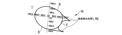
図4は、好ましい一実施形態のロータブレード1について、ロータブレードプロフィル10の薔薇棘状部プロフィルの一例を示す。ハブ領域Iにおける薔薇棘部プロフィルは、45%より大きい相対翼厚と5%より大きい(相対)後縁とを有する翼厚プロフィルであり、吸引面S側及び与圧面D側に夫々棘状延長部R1及びR2の形での薔薇棘状部を有する。後縁Fから測定される棘長さは、25%未満であり、かつ、後縁の相対厚みより大きい、即ちとりわけ5%より大きい。ロータブレードプロフィルは、既に、ある迎角をなして(ツイストされて(getwistet))記載されているが、この迎角はハブ領域のハブ近位領域においては何れにせよ0°〜70°、とりわけ0°〜45°とすることができ、この場合寧ろ増大する。
FIG. 4 shows an example of a rose bar profile of the
図5は、付加的な渦発生器(ジェネレータ)W1、W2を備えた図4のロータブレードプロフィルの一例を示す。ここで、渦発生器は吸引面S側及び与圧面D側に配されている。 FIG. 5 shows an example of the rotor blade profile of FIG. 4 with additional vortex generators W1, W2. Here, the vortex generator is arranged on the suction surface S side and the pressurization surface D side.
図6は、一実施形態のロータブレード1の複数の異なるプロフィル(翼厚プロフィル)形状の分布の一例を示す。ロータブレード1には、断面毎に翼厚2及び翼弦長3が記載されている。ロータブレード1は、一端部にロータブレード翼根部4を、該一端部の反対側の端部にロータブレード翼端の取り付けのための接続領域5を有する。ロータブレード翼根部4においては、ロータブレードは大きな翼弦長3を有する。接続領域5においては、翼弦長3はそれに対して極めて格段により小さい。翼弦長は、プロフィル根部(Profilwurzel)と称されることもあるロータブレード翼根部4から出発し、中央領域IIに至るまで明白に減少する。
FIG. 6 shows an example of distribution of a plurality of different profile (blade thickness profile) shapes of the
図7は、吸引面側の薔薇棘状部と与圧面側の薔薇棘状部の間のブレードプロフィルの谷部(溝部:Kehle)Kにおける、即ち、吸引面側の棘状延長部R1と与圧面側の棘状延長部R2の間の谷部Kにおける、比較的安定な谷部渦Wが吸引面の方向に形成されている様子を示す。左回りの(反時計回り)の谷部渦は吸引面Sから吸引面側の棘状延長部R1と与圧面側の棘状延長部R2の間の谷部Kに空気を吸い込み、吸引面上の流れの剥離を妨げる。与圧面Dにおける与圧面側流れは、付加的に、谷部渦Wを安定化する。比較的安定な谷部渦と共同で、ブレードプロフィルは、ハブ領域Iにその限りで谷部渦によって延長された翼弦長を有し、その結果、より長い流線(Stroemlinie)が形成される。いわば、ブレードプロフィルの翼弦長は安定な谷部渦によって延長されている。このため、谷部渦が安定である限り、揚力値は改善される。これは、棘状延長部の吸引側薔薇棘状部及び与圧側薔薇棘状部によって保証される。付加的に、図7のロータブレードは複数の渦発生器を備えており、そのため、境界面における流れの剥離は予想より早くには生じない。これにより、ブレードプロフィルの薔薇棘状延長部の吸引側薔薇棘状部と与圧側薔薇棘状部の間の谷部における谷部渦のために安定な圧力条件が得られる。図7は、迎角が7°の流れによるロータブレードの周囲流(Umstroemung)の一例を示す−しかしながら、本発明のコンセプトは、そのような小さな迎角に決して限定されておらず、寧ろ、迎角が30°のより不都合な場合さえも対象とする。なお、図7は、基本原理と薔薇棘状部の使用による明白な材料節約の可能性を示している。渦発生器も、図示されているよりもより小さくされることが可能であり、従って薔薇棘状部は比較的より小さくなる。 FIG. 7 is a graph showing a valley (groove: Kehle) K of the blade profile between the rose barbs on the suction surface side and the rose barbs on the pressurizing surface side, that is, the spine extensions R1 on the suction surface side. It shows that a relatively stable valley vortex W is formed in the direction of the suction surface in the valley K between the spine-shaped extensions R2 on the pressure surface side. The counterclockwise (counterclockwise) valley vortex sucks air from the suction surface S into the valley K between the spine-shaped extension R1 on the suction surface side and the spine-shaped extension R2 on the pressure surface side. Hinder flow separation. The pressure side flow on the pressure surface D additionally stabilizes the valley vortex W. In cooperation with the relatively stable trough vortex, the blade profile has a chord length in the hub region I which is extended by the trough vortex to the extent that it results in a longer streamline (Stroemlinie). . So to speak, the chord length of the blade profile is extended by a stable valley vortex. Therefore, the lift value is improved as long as the valley vortex is stable. This is ensured by the suction and compression side barbs of the barb extension. Additionally, the rotor blade of FIG. 7 is equipped with multiple vortex generators so that flow separation at the interface does not occur earlier than expected. This provides a stable pressure condition due to the valley vortex in the valley between the suction-side and pressure-side rose barbs of the rose barbed extension of the blade profile. FIG. 7 shows an example of the rotor blade ambient flow (Umstroemung) with a 7 ° angle of attack-however, the concept of the invention is in no way limited to such a small angle of attack, but rather to the angle of attack. Even the more inconvenient case of a 30 ° angle is of interest. It should be noted that FIG. 7 illustrates the basic principle and the potential for obvious material savings due to the use of rose barbs. The vortex generator can also be made smaller than shown, so that the barbs are relatively smaller.
図8は、(A)に図7の薔薇棘状部プロフィルを座標表示し、該プロフィルに属する流れの推移を(B)に示す。同図においては、とりわけ、図7に示した吸い込まれた流れが棘状部R1とR2の間の安定化された渦Wとして形成される様子を見出すことができる。 FIG. 8 shows the rose spine profile of FIG. 7 in coordinates in (A), and the transition of the flow belonging to the profile is shown in (B). In this figure it can be seen, inter alia, that the sucked flow shown in FIG. 7 is formed as a stabilized vortex W between the barbs R1 and R2.
図9は、一実施形態のロータブレード900の側面図であり、その全長L即ち0%〜100%が示されている。ロータブレード900は、一端部にロータブレード翼根部904を、該一端部の反対側の端部にロータブレード翼端部907を有する。ロータブレード翼端部907は、接続領域905においてロータブレードの残りの部分と結合する。ロータブレード翼根部904においては、ロータブレードは大きな翼弦長を有する。接続領域905及びロータブレード翼端部907においては、翼弦長はそれに対し極めて格段により小さい。翼弦長は、プロフィル根部(Profilwurzel)と称されることもあるロータブレード翼根部904から出発し、中央領域906に至るまで明白に減少する。中央領域906には、分離箇所(位置)を設けることができる(図9には不図示)。中央領域906から接続領域905に至るまで、翼弦長はほぼ一定である。
FIG. 9 is a side view of the
ロータブレード900は、ロータブレード翼根部904の領域においてツーピース構造(2つの部分からなる構造)を有する。従って、ロータブレード900は、基本プロフィル909と、該基本プロフィルに配された、ロータブレードの翼弦長を大きくするための更なる部分908とから構成される。ここで、更なる部分908は、例えば、基本プロフィル909に接着されている。そのようなツーピース構造は、建設地への輸送の際の取り扱いがより容易であり、かつ、より容易に製造可能である。
The
更に、図9には、ハブ接続領域910を見出すことができる。ハブ接続領域910を介して、ロータブレード900はロータハブに接続(結合)される。
Further, in FIG. 9, a
図10は、図9のロータブレード900の他の側面図である。基本プロフィル909、翼弦長延長化部分908、中央領域906、ロータブレード翼根部904及びハブ接続領域910並びにロータブレード翼端部907への接続領域905を有するロータブレード900を見出すことができる。ロータブレード翼端部907はいわゆるウィングレットとして構成可能である。これによって、渦はロータブレード翼端部において減少される。
FIG. 10 is another side view of the
図9の詳細部分図において、部分908は、吸引面側薔薇棘状部R1と与圧面側薔薇棘状部R2の間の谷部Kを有する後縁部材として図示されている。尤も、全体的に見れば、後縁部材の深さ(翼弦方向の長さ:Tiefe)はより小さく(短く)なる。なぜなら、谷部渦が好ましく安定的に形成されるため、ブレードプロフィルの有効相対翼厚がハブ領域において増大されているからである。
In the detailed partial view of FIG. 9, the
図10の詳細部分図では、後縁部材は、一方ではAに鋸歯形状(ないしギザギザ形状:Serrationsform)を有しないものとして、他方ではBに鋸歯形状を有するものとして図示されている。必要に応じ、とりわけ鋸歯形状又は他の流れ安定化措置によって、谷部渦形成を支援することができ、それによって、ハブ領域におけるブレードプロフィルの有効相対翼厚を大きくすることができる。 In the detailed partial view of FIG. 10, the trailing edge member is shown on the one hand as having no serrated (or serrated) shape at A and on the other as having a serrated shape at B. If desired, among others, sawtooth shapes or other flow stabilizing measures can assist in valley vortex formation, thereby increasing the effective relative blade thickness of the blade profile in the hub region.
図11は―上側の部分に見出すことができるように―後縁部材を備えた第1変形形態としての好ましい一実施形態を示す。後縁部材は、例えば別途に(独立の部材として)付設される後縁ボックス(状体)として構成されるが、これについては既に図9及び図10に部分908として示されている。
FIG. 11—as it can be found in the upper part—shows a preferred embodiment as a first variant with a trailing edge member. The trailing edge member is configured, for example, as a trailing edge box that is attached separately (as an independent member), which is already shown as
ハブ領域Iにおいて翼弦長が拡大されている様子が相応に図示されているロータブレード1は、とりわけ図9及び図10との関連において既に説明されている−棘状延長部を有する後縁部材の場合、即ち部分908としては、後縁部材の深さ(翼弦方向の長さ:Tiefe)は、揚力値及び滑空値(Gleitwert)が類似する場合、棘状延長部を有しない後縁部材の場合よりも、より小さく(短く)なる。従って、そのようなロータブレード1の翼弦長は、上記の安定な谷部渦形成のために比較的縮小(短縮)されることができ、そのため、ブレードプロフィルの有効相対翼厚はハブ領域において拡大されることができる。谷部渦が好ましく安定的に形成されるため、ハブ領域におけるブレードプロフィルの有効相対翼厚を拡大することができるため、このことは好適であるが、不可欠ではなく、図6に示されているようなロータブレード1に転換(変形)することも可能である。
A
図11は、ロータブレード1’として示されている第2変形形態としての特に好ましい更なる一実施形態も示している。この第2変形形態の場合、棘状延長部はハブ領域においてロータブレードのコアの後縁Fに「直接的に」形成されているが、棘状延長部R1、R2は(紙面において)破線L’の下方に留まっている;即ち、破線L’は棘状延長部R1、R2の後方の(後側の)エッジを形成する。ロータブレード1の後縁部材908は、ロータブレード1’では省かれている。
FIG. 11 also shows a particularly preferred further embodiment as a second variant, shown as rotor blade 1 '. In the case of this second variant, the barbs are formed "directly" in the hub region on the trailing edge F of the core of the rotor blade, whereas the barbs R1, R2 are (in the plane of the drawing) the dashed line L. Stays below '; that is, the dashed line L'forms the posterior (posterior) edge of the barb extensions R1, R2. The trailing
その限りにおいて、ロータブレード1’の翼弦長は、破線L’の(紙面の)下側の領域において制限されている。その限りにおいて、ロータブレード1’は、明白により短い(小さい)翼弦長(コード長:Sehnenlaenge)を備えて構成され、それにも拘らず、図示されているように、その揚力値及び滑空値は顕著かつ有利である。これにより、ロータブレード1’の極めて著しい軽減(縮小)、従って、著しく改善された輸送性能が達成される。
To that extent, the chord length of the rotor blade 1'is limited in the region below the dashed line L '(in the plane of the drawing). To that extent, the
ロータブレード1’はハブ領域Iにおいて格別に効率的に製造可能であるが、このことは、50%より大きい、とりわけ75%より大きい相対翼厚を有する上記の翼厚プロフィルとしてのコアに−即ち比較的大きな相対後縁厚みを有するコアの後縁に−棘状延長部が設けられることによって、とりわけ(図12に示されたこの実施形態の対応箇所に示されているように)棘状延長部のみが設けられることによって達成される。
The
50%より大きい、とりわけ75%より大きい有利には相対翼厚を有する厚みプロフィル(翼厚プロフィル)を有する実質的に円筒形又は卵形の巻回体は、例えば図13に明確に見出すことができるように、ハブ遠位ハブ領域I2からハブ近位領域I1に向かって、ハブの接続領域における100%までの有利な相対翼厚を有する円筒形厚みプロフィル(翼厚プロフィル)に至るまで発達する(大きくなる)。 Substantially cylindrical or oval windings with a thickness profile (blade thickness profile) having a relative blade thickness of greater than 50%, in particular greater than 75%, can be clearly seen, for example, in FIG. As possible from the hub distal hub region I 2 towards the hub proximal region I 1 up to a cylindrical thickness profile (vane thickness profile) with an advantageous relative blade thickness of up to 100% in the hub's connecting region. Develop (get bigger).
ロータブレード1’のためにも、ロータブレード1のためにも、ロータブレード1、1’が長さ方向において組み当てられる分離箇所Rが設けられる。
Both for the rotor blade 1'and for the
図12は、ハブ領域に認識可能な棘状延長部を有する、ロータブレードの好ましい一実施形態のハブ領域Iの斜視立体図である。ハブ領域のハブ近位第1領域において、翼厚プロフィル(翼型)はその後縁に棘状延長部を有し、第2領域にも即ちハブ領域のハブ遠位第2領域において、翼厚プロフィルの後縁は棘状延長部を有する平坦後縁である。 FIG. 12 is a perspective view of a hub region I of a preferred embodiment of a rotor blade having a discernible barb extension in the hub region. In the hub proximal first region of the hub region, the airfoil thickness profile (airfoil) has a barb extension on its trailing edge and also in the second region, i.e. in the hub distal second region of the hub region. The trailing edge is a flat trailing edge with barbed extensions.
ロータブレード1’は、トーラス状に(膨出状:wulstartig)拡幅(拡径)された分離箇所Rを備えたそのハブ領域Iについて、図12に斜視図で示されている。図12のロータブレード1’の斜視図から、翼厚プロフィルはハブ領域Iにおいて、実質的な楕円(長円)形から、長さ方向においてハブに向かって卵形に推移し(変化し)、最後に円筒形をなすコア11’(これは巻回体WTとして構成されている)として形成されていることが分かる、これについては図13に相応に示されている。
The
コア11’の吸引面Sには第1棘状延長部R1が、コア11’の与圧面Dには第2棘状延長部R2が設けられている、詳しくは夫々その後縁Fに設けられている。かくして、図12に見出される谷部Kが形成される、詳しくは、後縁Fの吸引面側棘状延長部R1と与圧面側棘状延長部R2の間の、後縁Fによって形成される、実質的に平坦な、第1棘状延長部R1と第2棘状延長部R2の間の底部を備えた谷部Kが形成される。 The suction surface S of the core 11 'is provided with a first barb-like extension R1 and the pressurizing surface D of the core 11' is provided with a second barb-shaped extension R2. There is. Thus, the valley K found in FIG. 12 is formed, in particular by the trailing edge F, between the suction side spine extension R1 and the pressure side spine extension R2 of the trailing edge F. , A substantially flat, valley K with a bottom between the first barb extension R1 and the second barb extension R2 is formed.
図13は、図12及び図11に関連して、図11に示した矢視A−A断面、矢視B−B断面及び矢視C−C断面を夫々部分図(A)、(B)及び(C)に示すが、ロータブレード1’の相応の翼厚プロフィルは、ハブに向かって、50%より大きい相対翼厚、次いで、75%より大きい相対翼厚、最後に実用上100%の相対翼厚を有する−更に、図13は、計算(シミュレート)による流速の分布も示す。流速は陰影として(陰影付け(シャドーイング)で)示されているが、これにより、巻回体WTに2つの棘状延長部R1、R2の間の谷部Kにおける谷部渦Wが見出される−これに関しては以下において参照される。
FIG. 13 is a partial view (A) and (B) of the AA cross section, the BB cross section and the CC cross section shown in FIG. 11 in relation to FIGS. 12 and 11, respectively. And (C), the corresponding blade thickness profile of the
図13の(A)、(B)及び(C)に示したプロフィルから分かることは、翼弦長3に対する翼厚2の比として定義される(図6参照)相対翼厚及び/又は絶対翼厚2は、ロータブレード翼端部5、7からロータブレード翼根部4に向かって減少することである;詳しくは、相対翼厚はまず45%未満から50%超に増加し、更に、75%超に増加し、最終的に、ロータブレード翼根部4ないしハブにおける円筒形ブレード接続部の実用上100%の相対翼厚に至る。
What can be seen from the profiles shown in FIGS. 13A, 13B and 13C is defined as the ratio of
更に分かることは、第1棘状延長部R1と第2棘状延長部R2の間の―ロータブレード1’の実用上平坦な後縁Fによって形成される―谷部Kの平坦底部は、ハブに近いプロフィルでは(図13(A)に示されているように)外部に向かって(凸状に)湾曲されていることである。即ち、ハブ近位領域I1では底部は外側に湾曲されているのに対し、中央ハブ領域I(これは図13(B)に記載されている)ではこの底部は比較的平坦であり、ハブ領域Iのハブ遠位領域I2では底部は(図13(C)において見出すことができるように)内部に向かって湾曲されている。 It will be further seen that between the first barbed extension R1 and the second barbed extension R2-formed by the practically flat trailing edge F of the rotor blade 1'-the flat bottom of the valley K is A profile close to is curved outward (as shown in FIG. 13A) (convex). That is, in the hub proximal region I 1 , the bottom is curved outward, whereas in the central hub region I (which is described in FIG. 13B), the bottom is relatively flat and the hub In the hub distal region I 2 of region I, the bottom is curved inward (as can be seen in FIG. 13 (C)).
更に、図12から分かることは、後縁Fにおける第1棘状延長部R1及び第2棘状延長部R2は60°未満の円周角で配置されていること、即ち、図12に示した例では凡そ45°の円周角α1、α2で配置されていることである。棘状延長部R1、R2の円周角α1、α2は、この場合、翼厚プロフィル軸(ロータブレード1’の翼厚プロフィルの翼弦A)を基準として測定されている。 Further, it can be seen from FIG. 12 that the first barbed extension R1 and the second barbed extension R2 at the trailing edge F are arranged at a circumferential angle of less than 60 °, ie shown in FIG. In the example, they are arranged at circumferential angles α1 and α2 of about 45 °. The circumferential angles α1, α2 of the barb-like extensions R1, R2 are in this case measured with reference to the blade thickness profile axis (chord A of the blade thickness profile of the rotor blade 1 ').
後縁Fにおける第1棘状延長部R1の吸引面Sにおける円周角α1は、翼端の方向にほぼ一定の円周角α1で推移する。与圧面Dにおいては、後縁Fにおける第2棘状延長部R2のための円周角α2は、図12に見出すことができるように、翼端領域IIIの方向に減少する。このことは、2つの棘状延長部R1、R2は互いに接近するよう延在し、ハブ領域Iの終端部の交点Tにおいて合流する(合体する)ことを意味する。これ(交点T)は、2つの棘状延長部R1、R2に対する円周角がほぼ0°、又は場合により円周角α1が一定の場合はそれ以上、である位置にほぼ相当する。 The circumferential angle α1 at the suction surface S of the first barbed extension R1 at the trailing edge F changes at a substantially constant circumferential angle α1 in the blade tip direction. At the pressure surface D, the circumferential angle α2 for the second barb extension R2 at the trailing edge F decreases in the direction of the wing tip region III, as can be seen in FIG. This means that the two barbs R1 and R2 extend so as to approach each other and merge (merge) at the intersection T of the end of the hub region I. This (intersection T) corresponds approximately to a position where the circumferential angle with respect to the two barbed extensions R1, R2 is approximately 0 °, or possibly even greater when the circumferential angle α1 is constant.
図12から分かるように、ハブ領域Iの第1領域において、詳しくはハブ領域Iのハブ近位領域I1において、翼厚プロフィル(翼型)はその平坦後縁に比較的大きな第1相対翼厚と棘状延長部を有する。更に、ハブ領域Iの第2領域において、とりわけハブ領域Iのハブ遠位領域I2において、翼厚プロフィル(翼型)の後縁は棘状延長部を有しない尖頭状後縁又は同様に棘状延長部を有するがより小さい第2相対翼厚を有する平坦後縁を有する。 As can be seen from FIG. 12, in the first region of the hub region I, more specifically in the hub proximal region I 1 of the hub region I, the blade thickness profile (airfoil) has a relatively large first relative blade at its flat trailing edge. Has a thick and barbed extension. Furthermore, in the second region of the hub region I, and in particular in the hub distal region I 2 of the hub region I, the trailing edge of the airfoil profile has a pointed trailing edge without spinous extensions or similar. Has a flattened trailing edge with a barbed extension but a smaller second relative wing thickness.
与圧面側棘状延長部R2は、いわゆるロータブレード1’のツイスト(ねじれ:Twist)がかけられている;即ち、迎角γが翼端領域IIIの方向に減少している−これについては既に説明した図6に見出すことができるが、図12においても明確に見出すことができる。同図では部分的にのみ記載されている中央領域において、ロータブレードの翼厚プロフィルは、既に、吸引面及び与圧面の合流した第1及び第2棘状部R1、R2から構成される尖頭状[切頭状]後縁を有する。換言すれば、ロータブレード1’は、吸引面及び与圧面の合流した第1及び第2棘状部R1、R2から構成される切頭状後縁(図3)を有し、相対後縁厚みは5%又はそれ未満の範囲にある−図12には図示されていない翼端領域においては、ロータブレードの翼厚プロフィルは尖頭状後縁(図2)を有する。
The pressure-side barbed extension R2 is twisted by the so-called rotor blade 1 '; that is, the angle of attack γ decreases in the direction of the tip region III-for this already. It can be found in the described FIG. 6, but also clearly in FIG. In the central region, which is only partially shown in the figure, the blade thickness profile of the rotor blade is already a cusp composed of first and second barbs R1 and R2 that merge the suction and pressure surfaces. The shape has a trailing edge. In other words, the
更に分かることは、ハブ領域Iのハブ近位領域I1の吸引面側の後縁Fの第1棘状延長部R1は、ロータブレード1’の与圧面側の後縁Fの第2棘状延長部R2の相対棘長さ(深さ)よりもより短い(より小さい)相対棘長さを有することである。更に、図12から分かることは、ハブ領域Iのハブ遠位領域の与圧面側の後縁の第2棘状延長部R2は、吸引面S側の後縁の第1棘状延長部R1の配向(ないし方位:Ausrichtung)よりもより大きく与圧面に向かって傾けられた配向(ないし方位)を有することである。これは、第1棘状延長部R1についての配向角β1が第2棘状延長部R2についての配向角β2よりもより大きいことによって表されている。 Further it is seen, first barb-like extension R1 edge F of the suction surface side of the hub proximal region I 1 of the hub region I, the rotor blades 1 'second spiny edges F of the pressurization side of the That is, it has a shorter (smaller) relative barb length than the relative barb length (depth) of the extension R2. Further, it can be seen from FIG. 12 that the second barbed extension R2 at the trailing edge on the pressure side of the hub distal region of the hub region I is the same as the first barbed extension R1 at the trailing edge on the suction surface S side. The orientation (or azimuth) is larger than the orientation (or azimuth: Ausrichtung). This is represented by the orientation angle β1 for the first barbed extension R1 being larger than the orientation angle β2 for the second barbed extension R2.
更に、後縁Fの第2棘状延長部R2は、第2棘状延長部R2の与圧面の下面R2uに与圧面Dに向かって湾曲された推移を有する。これは、第2棘状延長部R2の与圧面について、与圧面Dに向かって湾曲された推移は増大する曲率(Kruemmung)を有することを意味する。これによって達成可能な揚力効果(作用)は、付加的に、いわゆる、湾曲リップ(唇状部:Lippe)によって、例えば図13(C)に見出すことができるようなスポイラリップ(Spoiler-Lippe)又はガーニーフラップ(Guerney-Flap)等によって、一層強化されることができる。これにより、与圧面D上の圧力は大きくなり、従って、揚力値も大きくなる。 Furthermore, the second barbed extension R2 of the trailing edge F has a curve that curves towards the pressure surface D on the underside R2u of the pressure surface of the second barbed extension R2. This means that for the pressure-applying surface of the second barb extension R2, the curve curved towards the pressure-applying surface D has an increasing curvature (Kruemmung). The lift effect that can be achieved by this is additionally due to the so-called curved lip (Lippe), for example the Spoiler-Lippe as can be found in FIG. It can be further strengthened by a Guerney-Flap or the like. As a result, the pressure on the pressurizing surface D increases, and the lift value also increases.
この実施形態は、図12及び図11においてロータブレード1’として示されているように、谷部Kの領域において、0.01Ma〜0.1Maであり、以って、谷部渦Wの形成を格別に支援しかつ該渦を安定化する流速を実現することは明らかである。
In this embodiment, as shown as the
滑空数(揚抗比)は―(図11の矢視A−A、B−B及びC−C断面についての)図13(A)、(B)及び(C)及び図14に示されているように―依然として比較的大きい、詳しくは、5°までの迎角γの場合、矢視A−A断面については依然として少なくとも2.5までの値であり、矢視B−B断面については依然として8までの値であり、矢視C−C断面についてはそのうえさらに依然として10までの値である。これらは、ロータブレード1’の構造的(機械的)な翼弦長は明白により小さいにも拘らず、図13から見て取ることができるような安定化された谷部渦Wによる翼弦長の「有効な(effektiv)」増大により最終的に実現可能な滑空数である。
The glide number (lift-drag ratio) is shown in FIGS. 13 (A), (B) and (C) and FIG. 14 (for the cross sections AA, BB and CC in FIG. 11). As is-relatively large, in particular for angles of attack γ of up to 5 °, still values of at least 2.5 for the section AA taken along arrow and still for the section BB taken along arrow. Values up to 8, and still further up to 10 for the CC cross section. These are due to the stabilized valley vortices W as can be seen from FIG. 13, despite the fact that the structural (mechanical) chord length of the
換言すれば−図13から分かるように−ロータブレード1’の「有効(実効)」翼弦長は(いわゆる谷部渦のために)本来的な後縁Fを超えて外側に延長される、とりわけ少なくとも20%〜50%までだけ延長される−ないしは棘状延長部R1、R2の後縁を超えて20%までだけ、少なくとも10%までだけ大きくされる。 In other words-as can be seen from Fig. 13-the "effective" chord length of the rotor blade 1'is extended outward (because of the so-called valley vortex) beyond the original trailing edge F, In particular, it is extended by at least 20% to 50% -or increased beyond the posterior edges of the barb extensions R1, R2 by 20%, by at least 10%.
この有利な効果は、流れの剥離は渦Wの後方(下流)においてようやく見出されるのに対し、流れは棘状延長部の構造的(機械的)後縁からは依然として剥離しないことからもたらされることは明らかである。
以下に、本発明の態様を付記する。
(態様1)風力発電装置のための、吸引面と与圧面を有するロータブレード。ロータブレードは、
・ロータブレードをロータハブに取り付けるためのハブ領域のロータブレード翼根部と、
・該ロータブレード翼根部の反対側の翼端領域に位置付けられたロータブレード翼端部と
を有する。
・前記ハブ領域の範囲において少なくとも部分的に、ロータブレードは、その後縁に棘状延長部を有する翼厚(翼断面)プロフィルを有する。
前記ハブ領域の範囲において少なくとも部分的に、前記翼厚プロフィルは、
・前記吸引面側の前記後縁の第1棘状延長部、及び、
・前記与圧面側の前記後縁の第2棘状延長部
を有する。
前記ハブ領域の範囲において少なくとも部分的に、前記翼厚プロフィルは、前記吸引面及び/又は前記与圧面上に、流れスタビライザ及び/又は渦発生器を有する。
(態様2)上記のロータブレードにおいて、前記ハブ領域の範囲において少なくとも部分的に、前記翼厚プロフィルは、40%より大きい、とりわけ45%より大きい、相対翼厚を有する。
(態様3)上記のロータブレードにおいて、前記ハブ領域において、前記後縁は、所定の相対翼厚を有する、とりわけ5%より大きい相対翼厚を有する平坦な又は湾曲した後縁である。
(態様4)上記のロータブレードにおいて、前記後縁から測定された前記棘状延長部の相対棘長さは25%未満であり及び/又は少なくとも前記後縁の所定の相対翼厚より大きく、とりわけ5%より大きく、
有利には、最大相対棘長さは15%〜25%である。
(態様5)上記のロータブレードにおいて、前記ハブ領域の範囲において少なくとも部分的に、前記後縁は鋸歯形状を有する。
(態様6)上記のロータブレードにおいて、前記ハブ領域の範囲において少なくとも部分的に、前記翼厚プロフィルは前記吸引面及び/又は前記与圧面上に、スポイラ、境界層フェンス、境界層吸引部からなる群から選択される流れスタビライザを有する。
(態様7)上記のロータブレードにおいて、前記ハブ領域の範囲において少なくとも部分的に、前記翼厚プロフィルは前記吸引面及び/又は前記与圧面上に、フィン、スタッド、ディンプル、ウェブ、噴出又は吸引構造体からなる群から選択される渦発生器を有する。
(態様8)上記のロータブレードにおいて、
・前記ハブ領域の第1領域において、とりわけ前記ハブ領域のハブ近位領域において、前記翼厚プロフィルはその平坦後縁に第1相対翼厚と前記棘状延長部とを有し、
・前記ハブ領域の第2領域において、とりわけ前記ハブ領域のハブ遠位領域において、前記翼厚プロフィル(の後縁)は、棘状延長部を有しない尖頭状後縁を有するか又は前記棘状延長部を有するより小さい第2相対翼厚を有する平坦後縁を有する。
(態様9)上記のロータブレードにおいて、
・前記ハブ領域の第1領域において、とりわけ前記ハブ領域のハブ近位領域において、前記翼厚プロフィルはその平坦後縁に前記棘状延長部を有し、
・前記ハブ領域の第2領域において、とりわけ前記ハブ領域のハブ遠位領域において、前記翼厚プロフィル(の後縁)は、棘状延長部を有しない平坦後縁を有する。
(態様10)上記のロータブレードにおいて、前記ハブ領域の、第1領域、とりわけ前記ハブ領域のハブ近位領域と、第2領域、とりわけ前記ハブ領域のハブ遠位領域との間において、前記翼厚プロフィルは最大翼弦長を有する。
(態様11)上記のロータブレードにおいて、翼弦長に対する翼厚の比として定義される相対翼厚は、前記ハブ領域のロータブレード翼根部と前記翼端領域のロータブレード翼端部の間の領域、とりわけ中央領域に、局所的最大を有する。
(態様12)上記のロータブレードにおいて、前記局所的最大の相対翼厚は、35%〜50%、とりわけ40%〜45%である。
(態様13)上記のロータブレードにおいて、ロータブレードは、前記局所的最大の範囲に、1500mm〜3500mmの絶対翼弦長を有する。
(態様14)上記のロータブレードにおいて、
・ロータブレードは、第1ロータブレード部分と第2ロータブレード部分とから構成されており、
・該第1ロータブレード部分は前記ロータブレード翼根部を有し、かつ、該第2ロータブレード部分は前記ロータブレード翼端部を有し、
・該第1及び第2ロータブレード部分は、分離箇所において互いに結合されており、
とりわけ、該分離箇所は、ロータブレード翼根部とロータブレード翼端部との間の前記中央領域に及び/又は翼弦長に対する翼厚の比として定義される相対翼厚の局所的最大の領域に配されている。
(態様15)上記のロータブレードにおいて、ロータブレードは、前記ハブ領域の第1領域、とりわけ前記ハブ領域のハブ近位領域に、少なくとも3900mmの絶対翼弦長、とりわけ4000mm〜8000mmの範囲の絶対翼弦長を有する。
(態様16)上記のロータブレードにおいて、ロータブレードは、前記ロータブレード翼根部から出発してその全長の90%〜95%の範囲に、最大で1000mmの絶対翼弦長、とりわけ400mm〜700mmの範囲の絶対翼弦長を有する。
(態様17)上記のロータブレードにおいて、ロータブレードは、前記中央領域に、前記ハブ領域における翼弦長の20%〜30%に相当する翼弦長を有する。
(態様18)上記のロータブレードにおいて、前記ハブ領域の範囲において少なくとも部分的に、前記翼厚プロフィルは50%より大きい、とりわけ75%より大きい相対翼厚を有し、該翼厚プロフィルは実質的に円筒形ないし卵形のコアの形で、好ましくは実質的に円筒形ないし卵形の巻回体の形で形成されている。
(態様19)上記のロータブレードにおいて、前記翼厚プロフィルは、前記吸引面側に前記後縁の第1棘状延長部を有しかつ前記与圧面側に前記後縁の第2棘状延長部を有し、該第1棘状延長部と該第2棘状延長部との間には実質的に平坦底部を有する谷部が形成されており、
翼弦長に対する翼厚の比として定義される相対翼厚及び/又は絶対翼厚は、ロータブレード翼根部からロータブレード翼端部に向かって減少する。
(態様20)上記のロータブレードにおいて、前記第1棘状延長部と前記第2棘状延長部との間の谷部の平坦底部は、前記ハブ領域のハブ近位領域においては、外部に向かって湾曲されており、かつ、前記ハブ領域のハブ遠位領域においては、内部に向かって湾曲されている。
(態様21)上記のロータブレードにおいて、前記後縁の前記第1棘状延長部と前記第2棘状延長部は、60°未満の、とりわけ45°未満の円周角で配置されており、該円周角は迎角を有しない(迎角が0°の)翼厚プロフィル軸を基準として測定される。
(態様22)上記のロータブレードにおいて、前記ハブ領域において、とりわけ前記ハブ領域の前記ハブ近位領域において、前記吸引面側の前記後縁の前記第1棘状延長部は、前記与圧面側の前記後縁の前記第2棘状延長部の相対棘長さより短い相対棘長さを有する。
(態様23)上記のロータブレードにおいて、前記ハブ領域において、とりわけ前記ハブ領域の前記ハブ近位領域において、前記与圧面側の前記後縁の前記第2棘状延長部は、前記吸引面側の前記後縁の前記第1棘状延長部の配向よりもより大きく該与圧面に向かって傾けられている配向を有する。
(態様24)上記のロータブレードにおいて、前記ハブ領域において、前記吸引面側の前記後縁の前記第1棘状延長部は、円周角が実質的に一定のままで、前記翼端領域の方向に延伸し、かつ、前記与圧面側の前記後縁の前記第2棘状延長部は、円周角が実質的に減少しつつ、前記翼端領域の方向に延伸している。
(態様25)上記のロータブレードにおいて、前記ハブ領域において、前記後縁の前記第1棘状延長部と前記後縁の前記第2棘状延長部は合流する、とりわけ0°の円周角又はマイナスの円周角又はプラスの円周角の位置において合流する。
(態様26)上記のロータブレードにおいて、前記ハブ領域において、前記与圧面側の前記後縁の前記第2棘状延長部は、与圧面側の下面の該与圧面に向かって湾曲された推移を有する、とりわけ与圧面側の下面の該与圧面に向かって曲率が増加するよう湾曲された推移を有する。
(態様27)上記のロータブレードにおいて、前記ハブ領域において、前記与圧面側の前記後縁の前記第2棘状延長部は、とりわけ与圧面側の下面の該与圧面に向かって湾曲された推移に対する空気力学的な移行部を有する、該与圧面に向かって湾曲されたリップ、とりわけスポイラリップ又はガーニーフラップを有する。
(態様28)上記のロータブレードにおいて、前記第1棘状延長部と前記第2棘状延長部の間の谷部の領域における正規化された流れの単位Ma(マッハ)で表された流速は、0.01Ma〜最大で0.1Ma、とりわけ0.02Ma〜最大で0.06Maである。
(態様29)上記のロータブレードにおいて、滑空比(揚抗比)は、迎角(ツイスト)が5°までの場合、1より大きくかつ10より小さい、とりわけ前記ハブ領域のハブ近位領域から前記ハブ領域のハブ遠位領域に向かって、滑空比(揚抗比)は増大し及び/又はロータブレードの翼厚プロフィルの迎角(ツイスト)は減少する。
(態様30)ロータを有する風力発電装置であって、該ロータは上記のロータブレードを少なくとも1つ有する、風力発電装置。
This beneficial effect results from the fact that the flow separation is only found at the rear (downstream) of the vortex W, whereas the flow still does not separate from the structural (mechanical) trailing edge of the barb extension. Is clear.
The aspects of the present invention will be additionally described below.
(Aspect 1) A rotor blade having a suction surface and a pressure surface for a wind turbine generator. Rotor blades
A rotor blade blade root in the hub area for attaching the rotor blade to the rotor hub,
A rotor blade tip located in the tip region opposite the rotor blade root
Have.
At least partially in the region of the hub region, the rotor blades have a blade thickness (blade cross-section) profile with barbed extensions at their trailing edges.
At least in part in the region of the hub region, the airfoil thickness profile is
A first barbed extension of the trailing edge on the side of the suction surface, and
.Second barbed extension on the trailing edge on the pressure surface side
Have.
At least partly in the region of the hub region, the airfoil profile has a flow stabilizer and / or a vortex generator on the suction surface and / or the pressure surface.
(Aspect 2) In the rotor blade described above, the blade thickness profile has a relative blade thickness that is greater than 40%, and particularly greater than 45%, at least partially in the range of the hub region.
(Aspect 3) In the rotor blade described above, in the hub region, the trailing edge is a flat or curved trailing edge having a predetermined relative blade thickness, particularly having a relative blade thickness greater than 5%.
(Aspect 4) In the above rotor blade, the relative barb length of the barb extending portion measured from the trailing edge is less than 25% and / or at least greater than a predetermined relative blade thickness of the trailing edge, Greater than 5%,
Advantageously, the maximum relative barb length is between 15% and 25%.
(Aspect 5) In the rotor blade described above, the trailing edge has a sawtooth shape at least partially in the range of the hub region.
(Aspect 6) In the rotor blade described above, at least partially in the range of the hub region, the blade thickness profile includes a spoiler, a boundary layer fence, and a boundary layer suction portion on the suction surface and / or the pressure surface. Having a flow stabilizer selected from the group.
(Aspect 7) In the rotor blade described above, the blade thickness profile is at least partially in the range of the hub region, on the suction surface and / or the pressure surface, fins, studs, dimples, webs, jetting or suction structures. Having a vortex generator selected from the group consisting of bodies.
(Aspect 8) In the above rotor blade,
In the first region of the hub region, in particular in the hub proximal region of the hub region, the airfoil thickness profile has a first relative airfoil thickness and the barb extension at its flat trailing edge;
In the second region of the hub region, in particular in the hub distal region of the hub region, the airfoil profile has a pointed trailing edge without barb extensions or the barb Has a flatter trailing edge with a smaller second relative wing thickness having a profile extension.
(Aspect 9) In the above rotor blade,
In the first region of the hub region, in particular in the hub proximal region of the hub region, the airfoil thickness profile has the barb extension at its flat trailing edge,
-In the second region of the hub region, in particular in the hub distal region of the hub region, the airfoil thickness profile (trailing edge) has a flat trailing edge without barb extensions.
(Aspect 10) In the above rotor blade, the blade is provided between the first region, particularly the hub proximal region of the hub region, and the second region, especially the hub distal region of the hub region, of the hub region. The thick profile has a maximum chord length.
(Aspect 11) In the rotor blade described above, a relative blade thickness defined as a ratio of blade thickness to a chord length is a region between a rotor blade blade root portion in the hub region and a rotor blade blade tip portion in the blade tip region. , Having a local maximum, especially in the central region.
(Aspect 12) In the above rotor blade, the local maximum relative blade thickness is 35% to 50%, and particularly 40% to 45%.
(Aspect 13) In the rotor blade described above, the rotor blade has an absolute chord length of 1500 mm to 3500 mm in the local maximum range.
(Aspect 14) In the above rotor blade,
The rotor blade comprises a first rotor blade portion and a second rotor blade portion,
The first rotor blade portion has the rotor blade blade root and the second rotor blade portion has the rotor blade blade tip,
The first and second rotor blade parts are connected to each other at a separation point,
In particular, the separation point is in the central region between the rotor blade root and the rotor blade tip and / or in a local maximum region of relative blade thickness defined as the ratio of blade thickness to chord length. It is distributed.
(Aspect 15) In the above rotor blade, the rotor blade may have an absolute chord length of at least 3900 mm, particularly in the range of 4000 mm to 8000 mm, in the first region of the hub region, particularly in the hub proximal region of the hub region. Has chord length.
(Aspect 16) In the above rotor blade, the rotor blade starts from the root portion of the rotor blade and has a range of 90% to 95% of its entire length, and a maximum absolute chord length of 1000 mm, particularly a range of 400 mm to 700 mm. It has an absolute chord length of.
(Aspect 17) In the rotor blade described above, the rotor blade has a chord length corresponding to 20% to 30% of a chord length in the hub region in the central region.
(Aspect 18) In the rotor blade described above, at least partially in the range of the hub region, the blade thickness profile has a relative blade thickness of greater than 50%, especially greater than 75%, the blade thickness profile being substantially It is formed in the form of a cylindrical or oval core, preferably in the form of a substantially cylindrical or oval wound body.
(Aspect 19) In the rotor blade described above, the blade thickness profile has a first barb-shaped extension of the trailing edge on the suction surface side and a second barb-shaped extension of the trailing edge on the pressurizing surface side. And a trough portion having a substantially flat bottom is formed between the first barbed extension and the second barbed extension.
Relative and / or absolute blade thickness, defined as the ratio of blade thickness to chord length, decreases from the rotor blade root to the rotor blade tip.
(Aspect 20) In the rotor blade described above, the flat bottom portion of the valley portion between the first barbed extension portion and the second barbed extension portion may face outward in the hub proximal region of the hub region. And is curved toward the inside in the hub distal region of the hub region.
(Aspect 21) In the rotor blade described above, the first barbed extension and the second barbed extension of the trailing edge are arranged at a circumferential angle of less than 60 °, especially less than 45 °, The circumferential angle is measured with reference to the blade thickness profile axis having no angle of attack (at an angle of attack of 0 °).
(Aspect 22) In the rotor blade described above, in the hub region, particularly in the hub proximal region of the hub region, the first barb-like extension of the trailing edge on the suction surface side is on the pressure surface side. The relative barb length is shorter than the relative barb length of the second barb extension of the trailing edge.
(Aspect 23) In the rotor blade described above, in the hub region, particularly in the hub proximal region of the hub region, the second barb-shaped extension of the trailing edge on the pressurizing surface side is on the suction surface side. It has an orientation that is more inclined toward the pressure surface than the orientation of the first barb extension of the trailing edge.
(Aspect 24) In the rotor blade described above, in the hub region, the first barb-shaped extension of the trailing edge on the suction surface side has a circumferential angle that remains substantially constant, and Direction, and the second barbed extension of the trailing edge on the pressurizing surface side extends in the direction of the wing tip region while the circumferential angle is substantially reduced.
(Aspect 25) In the rotor blade described above, in the hub region, the first barbed extension of the trailing edge and the second barbed extension of the trailing edge meet, in particular a circumferential angle of 0 ° or They meet at a position with a negative or positive circumferential angle.
(Aspect 26) In the rotor blade described above, in the hub region, the second barb-shaped extension portion of the trailing edge on the pressurizing surface side may be curved toward the pressurizing surface on the lower surface on the pressurizing surface side. And, in particular, has a curved profile with increasing curvature towards the pressure-bearing surface on the underside of the pressure-bearing surface.
(Aspect 27) In the rotor blade described above, in the hub region, the second barb-shaped extension portion of the trailing edge on the pressurizing surface side is curved toward the pressurizing surface, especially on the lower surface on the pressurizing surface side. With a lip curved towards the pressure surface, in particular a spoiler lip or a Gurney flap, with an aerodynamic transition to.
(Aspect 28) In the rotor blade described above, the flow velocity represented by the normalized flow unit Ma (Mach) in the region of the valley between the first barbed extension and the second barbed extension is , 0.01 Ma up to 0.1 Ma, especially 0.02 Ma up to 0.06 Ma.
(Aspect 29) In the rotor blade described above, the glide ratio (lift-drag ratio) is larger than 1 and smaller than 10 when the angle of attack (twist) is up to 5 °, especially from the hub proximal region of the hub region to the above. Toward the hub distal region of the hub region, the glide ratio (lift-drag ratio) increases and / or the blade angle profile angle of attack (twist) of the rotor blade decreases.
(Aspect 30) A wind turbine generator having a rotor, the rotor having at least one rotor blade described above.
Claims (34)
・ロータブレード(1)をロータハブに取り付けるためのハブ領域(I)のロータブレード翼根部(4)と、
・該ロータブレード翼根部(4)の反対側の翼端領域(III)に位置付けられたロータブレード翼端部(5、7)と
を有し、
・前記ハブ領域の範囲において少なくとも部分的に、ロータブレードは、その後縁に棘状延長部を有する翼厚プロフィルを有し、
前記ハブ領域の範囲において少なくとも部分的に、前記翼厚プロフィルは、
・前記吸引面側の前記後縁の第1棘状延長部、及び、
・前記与圧面側の前記後縁の第2棘状延長部
を有し、
・前記ハブ領域の範囲において、前記後縁は平坦な又は湾曲した後縁であり、
・前記翼厚プロフィルは、前記吸引面側に前記後縁の第1棘状延長部を有しかつ前記与圧面側に前記後縁の第2棘状延長部を有し、該第1棘状延長部と該第2棘状延長部との間には平坦底部を有する谷部(K)が形成されており、
・前記第1棘状延長部と前記第2棘状延長部との間の谷部(K)の平坦底部は、前記ハブ領域(I)のハブ近位領域(I 1 )においては、外部に向かって湾曲されており、かつ、前記ハブ領域(I)のハブ遠位領域(I 2 )においては、内部に向かって湾曲されており、及び、
前記ハブ領域の範囲において少なくとも部分的に、前記翼厚プロフィルは、前記吸引面及び/又は前記与圧面上に、流れスタビライザ及び/又は渦発生器を有する、
ロータブレード。 A rotor blade for a wind turbine having a suction surface and a pressure surface,
A rotor blade blade root (4) in the hub region (I) for attaching the rotor blade (1) to the rotor hub,
A rotor blade tip (5, 7) located in a tip region (III) opposite the rotor blade root (4),
- at least partially in the region of the hub region, the rotor blades will then have a blade up-Rofiru having barb extensions to the edge,
At least in part in the region of the hub region, the airfoil thickness profile is
A first barbed extension of the trailing edge on the side of the suction surface, and
-Has a second barbed extension of the trailing edge on the pressure surface side,
In the region of the hub region the trailing edge is a flat or curved trailing edge,
The wing thickness profile has a first barbed extension of the trailing edge on the suction side and a second barb extension of the trailing edge on the pressure side, A valley (K) having a flat bottom is formed between the extension and the second barb-like extension,
The flat bottom of the valley (K) between the first barb-like extension and the second barb-like extension is external in the hub proximal region (I 1 ) of the hub region (I). Curved towards the inside and, in the hub distal region (I 2 ) of the hub region (I ), curved towards the inside, and
At least partially in the region of the hub region, the airfoil profile has a flow stabilizer and / or a vortex generator on the suction surface and / or the pressure surface.
Rotor blades.
前記ハブ領域の範囲において少なくとも部分的に、前記翼厚プロフィルは、40%より大きい相対翼厚を有する、
ロータブレード。 The rotor blade according to claim 1,
At least partially in the extent of the hub region, the airfoil thickness profile has a relative airfoil thickness of greater than 40%,
Rotor blades.
前記ハブ領域の範囲において、前記平坦な又は湾曲した後縁は、5%より大きい相対翼厚を有する、
ロータブレード。 The rotor blade according to claim 1 ,
Within the scope of the hub region, the edges after the flat or curved, that have a greater than 5% relative blade thickness,
Rotor blades.
前記後縁から測定された前記棘状延長部の相対棘長さは25%未満であり及び/又は少なくとも前記後縁の5%の相対翼厚より大きい、
ロータブレード。 The rotor blade according to claim 3,
The relative barb length of the barb extension measured from the trailing edge is less than 25% and / or is greater than at least 5% of the trailing edge relative wing thickness,
Rotor blades.
前記ハブ領域の範囲において少なくとも部分的に、前記後縁は鋸歯形状を有する、
ロータブレード。 The rotor blade according to any one of claims 1 to 4,
At least partially in the region of the hub region, the trailing edge has a sawtooth shape,
Rotor blades.
前記流れスタビライザはスポイラ、境界層フェンス、境界層吸引部からなる群から選択される、
ロータブレード。 The rotor blade according to claim 1 ,
Before Symbol flow stabilizer spoiler, boundary layer fences, Ru is selected from the group consisting of boundary layer suction unit,
Rotor blades.
前記渦発生器はフィン、スタッド、ディンプル、ウェブ、噴出又は吸引構造体からなる群から選択される、
ロータブレード。 The rotor blade according to claim 1 ,
Before Kiuzu generator fins, studs, dimples, web, Ru is selected from the group consisting of jet or suction structure,
Rotor blades.
・前記ハブ領域(I)のハブ近位領域(I1)において、前記翼厚プロフィルはその平坦後縁に第1相対翼厚と前記棘状延長部とを有し、
・前記ハブ領域(I)のハブ遠位領域(I2)において、前記翼厚プロフィルの後縁は、棘状延長部を有しない尖頭状後縁を有するか又は前記棘状延長部を有するより小さい第2相対翼厚を有する平坦後縁を有する、
ロータブレード。 The rotor blade according to any one of claims 1 to 7,
In the hub proximal region (I 1 ) of the hub region (I), the airfoil thickness profile has a first relative airfoil thickness and the barb extension at its flat trailing edge,
In the hub distal region (I 2 ) of the hub region (I), the trailing edge of the airfoil profile has a pointed trailing edge without spinous extensions or has the spinous extensions. A flat trailing edge having a smaller second relative blade thickness,
Rotor blades.
・前記ハブ領域(I)のハブ近位領域(I1)において、前記翼厚プロフィルはその平坦後縁に前記棘状延長部を有し、
・前記ハブ領域(I)のハブ遠位領域(I2)において、前記翼厚プロフィルの後縁は、棘状延長部を有しない平坦後縁を有する、
ロータブレード。 The rotor blade according to any one of claims 1 to 8,
In the hub proximal region (I 1 ) of the hub region (I), the airfoil thickness profile has the barb extension at its flat trailing edge,
In the hub distal region (I 2 ) of the hub region (I), the trailing edge of the wing thickness profile has a flat trailing edge without spinous extensions.
Rotor blades.
前記ハブ領域(I)の、前記ハブ領域(I)のハブ近位領域(I1)と、前記ハブ領域(I)のハブ遠位領域(I2)との間において、前記翼厚プロフィルは最大翼弦長を有する、
ロータブレード。 The rotor blade according to any one of claims 1 to 9,
Between the hub proximal region (I 1 ) of the hub region (I) and the hub distal region (I 2 ) of the hub region (I) of the hub region (I), the blade thickness profile is Has a maximum chord length,
Rotor blades.
前記翼厚プロフィルの翼弦長(3)に対する翼厚(2)の比として定義される相対翼厚は、前記ハブ領域(I)のロータブレード翼根部(4)と前記翼端領域(III)のロータブレード翼端部(5、7)の間の中央領域(II)に、局所的最大を有する、
ロータブレード。 The rotor blade according to any one of claims 1 to 10,
The relative blade thickness, defined as the ratio of the blade thickness (2) to the chord length (3) of the blade thickness profile, is the rotor blade root (4) and the blade tip region (III) of the hub region (I). Has a local maximum in the central region (II) between the rotor blade tips (5, 7) of
Rotor blades.
前記局所的最大の相対翼厚は、35%〜50%である、
ロータブレード。 The rotor blade according to claim 11,
The local maximum relative blade thickness is 35% to 50%,
Rotor blades.
ロータブレード(1)は、前記局所的最大の範囲に、1500mm〜3500mmの絶対翼弦長(3)を有する、
ロータブレード。 The rotor blade according to claim 11 or 12,
The rotor blade (1) has an absolute chord length (3) of 1500 mm to 3500 mm in the local maximum range,
Rotor blades.
・ロータブレード(1)は、第1ロータブレード部分と第2ロータブレード部分とから構成されており、
・該第1ロータブレード部分は前記ロータブレード翼根部(4)を有し、かつ、該第2ロータブレード部分は前記ロータブレード翼端部(7)を有し、
・該第1及び第2ロータブレード部分は、分離箇所において互いに結合されている、
ロータブレード。 The rotor blade according to any one of claims 1 to 13,
The rotor blade (1) comprises a first rotor blade portion and a second rotor blade portion,
The first rotor blade portion has the rotor blade root portion (4) and the second rotor blade portion has the rotor blade tip portion (7),
The first and second rotor blade portions are connected to each other at a separation point,
Rotor blades.
前記分離箇所は、ロータブレード翼根部(4)とロータブレード翼端部(7)との間の中央領域(II)に及び/又は前記翼厚プロフィルの翼弦長(3)に対する翼厚(2)の比として定義される相対翼厚の局所的最大の領域に配されている、
ロータブレード。 The rotor blade according to claim 14,
The separation portion is blade thickness to the rotor blade airfoil root (4) and the rotor blade tip portion (7) central region (II) and / or to chord length of the blade thickness profile (3) in between ( Located in the local maximum region of relative blade thickness, defined as the ratio of 2),
Rotor blades.
ロータブレード(1)は、前記ハブ領域(I)のハブ近位領域(I1)に、少なくとも3900mmの絶対翼弦長(3)を有する、
ロータブレード。 The rotor blade according to any one of claims 1 to 15,
The rotor blade (1) has an absolute chord length (3) of at least 3900 mm in the hub proximal region (I 1 ) of the hub region (I),
Rotor blades.
ロータブレード(1)は、前記ロータブレード翼根部(4)から出発してその全長の90%〜95%の範囲に、最大で1000mmの絶対翼弦長(3)を有する、
ロータブレード。 The rotor blade according to any one of claims 1 to 16,
The rotor blade (1) has an absolute chord length (3) of up to 1000 mm in the range of 90% to 95% of its total length, starting from the rotor blade blade root (4).
Rotor blades.
ロータブレードは、ロータブレード翼根部(4)とロータブレード翼端部(7)との間の中央領域(II)に、前記ハブ領域(I)における翼弦長の20%〜30%に相当する翼弦長を有する、
ロータブレード。 The rotor blade according to any one of claims 1 to 17,
The rotor blade corresponds to a central region (II) between the rotor blade blade root (4) and the rotor blade blade tip (7) and corresponds to 20% to 30% of the chord length in the hub region (I). Has a chord length,
Rotor blades.
前記ハブ領域の範囲において少なくとも部分的に、前記翼厚プロフィルは50%より大きい相対翼厚を有する、
ロータブレード。 The rotor blade according to any one of claims 1 to 18,
At least in part, the blade thickness profile to have a greater than 50% relative blade thickness in the range of the hub region,
Rotor blades.
前記翼厚プロフィルは実質的に円筒形ないし卵形のコア(11’)の形で形成されている、
ロータブレード。 The rotor blade according to any one of claims 1 to 19,
The wing thickness profile is formed in the form of a substantially cylindrical or oval core (11 '),
Rotor blades.
前記翼厚プロフィルの翼弦長(3)に対する翼厚(2)の比として定義される相対翼厚及び/又は絶対翼厚は、ロータブレード翼根部(4)からロータブレード翼端部(5、7)に向かって減少する、
ロータブレード。 A rotor blade according to any one of claims 1 to 20,
The relative blade thickness and / or the absolute blade thickness, defined as the ratio of the blade thickness (2) to the chord length (3) of the blade thickness profile, is calculated from the rotor blade root (4) to the rotor blade tip (5, Decrease towards 7),
Rotor blades.
前記後縁の前記第1棘状延長部(R1)と前記第2棘状延長部(R2)は、60°未満の円周角で配置されており、該円周角は迎角を有しない翼厚プロフィル軸を基準として測定される、
ロータブレード。 The rotor blade according to any one of claims 1 to 21,
The first barbed extension (R1) and the second barbed extension (R2) of the trailing edge are arranged at a circumferential angle of less than 60 °, the circumferential angle having no elevation angle. Measured with reference to the blade thickness profile axis,
Rotor blades.
前記ハブ領域(I)の前記ハブ近位領域(I1)において、前記吸引面側の前記後縁の前記第1棘状延長部は、前記与圧面側の前記後縁の前記第2棘状延長部の相対棘長さより短い相対棘長さを有する、
ロータブレード。 The rotor blade according to any one of claims 1 to 22,
In the hub proximal region (I 1 ) of the hub region (I), the first barb-shaped extension of the trailing edge on the suction surface side is the second barb-shaped portion of the trailing edge on the compression surface side. Having a relative barb length shorter than the relative barb length of the extension,
Rotor blades.
前記ハブ領域(I)の前記ハブ近位領域(I1)において、前記与圧面側の前記後縁の前記第2棘状延長部は、前記吸引面側の前記後縁の前記第1棘状延長部の配向よりもより大きく該与圧面に向かって傾けられている配向を有する、
ロータブレード。 The rotor blade according to any one of claims 1 to 23,
In the hub proximal region (I 1 ) of the hub region (I), the second barb-shaped extension of the trailing edge on the pressure surface side is the first barb-shaped portion of the trailing edge on the suction surface side. Having an orientation that is tilted toward the pressure surface to a greater extent than the orientation of the extension,
Rotor blades.
前記ハブ領域(I)において、前記吸引面(S)側の前記後縁の前記第1棘状延長部(R1)は、円周角(α1)が実質的に一定のままで、前記翼端領域(III)の方向に延伸し、かつ、前記与圧面(D)側の前記後縁の前記第2棘状延長部(R2)は、円周角(α2)が実質的に減少しつつ、前記翼端領域(III)の方向に延伸している、
ロータブレード。 The rotor blade according to any one of claims 1 to 24,
In the hub region (I), the first spine-shaped extension (R1) of the trailing edge on the suction surface (S) side has the circumferential angle (α1) substantially constant, While extending in the direction of the region (III), and the second spine-shaped extension (R2) of the trailing edge on the pressure-applying surface (D) side, the circumferential angle (α2) is substantially reduced, Extending in the direction of the wing tip region (III),
Rotor blades.
前記ハブ領域(I)において、前記後縁の前記第1棘状延長部(R1)と前記後縁の前記第2棘状延長部(R2)は合流する、
ロータブレード。 The rotor blade according to any one of claims 1 to 25,
In the hub region (I), the first barbed extension (R1) of the trailing edge and the second barb extension (R2) of the trailing edge meet.
Rotor blades.
前記ハブ領域(I)において、前記与圧面(D)側の前記後縁の前記第2棘状延長部(R2)は、与圧面側の下面の該与圧面に向かって湾曲された推移を有する、
ロータブレード。 The rotor blade according to any one of claims 1 to 26,
In the hub region (I), the second barbed extension (R2) of the trailing edge on the pressure surface (D) side has a curve that curves towards the pressure surface on the lower surface on the pressure surface side. ,
Rotor blades.
前記ハブ領域(I)において、前記与圧面側の前記後縁の前記第2棘状延長部は、該与圧面に向かって湾曲されたリップを有する、
ロータブレード。 The rotor blade according to any one of claims 1 to 27,
In the hub region (I), the second barbed extension of the trailing edge on the pressure surface side has a lip curved toward the pressure surface.
Rotor blades.
前記リップは、与圧面側の下面(U)の該与圧面に向かって湾曲された推移に対する空気力学的な移行部を有する、
ロータブレード。 The rotor blade according to claim 28,
The lip has an aerodynamic transition to the curved surface of the underside (U) on the pressure side towards the pressure side,
Rotor blades.
前記リップは、スポイラリップ又はガーニーフラップである、
ロータブレード。 The rotor blade according to claim 28 or 29,
The lip is a spoiler lip or a gurney flap,
Rotor blades.
前記第1棘状延長部と前記第2棘状延長部の間の谷部の領域における正規化された流れの単位Ma(マッハ)で表された流速は、0.01Ma〜最大で0.1Maである、
ロータブレード。 The rotor blade according to any one of claims 1 to 30,
The flow velocity expressed in the normalized flow unit Ma (Mach) in the region of the valley between the first barbed extension and the second barbed extension is from 0.01 Ma up to 0.1 Ma. Is,
Rotor blades.
滑空比は、迎角が5°までの場合、1より大きくかつ10より小さい、
ロータブレード。 The rotor blade according to any one of claims 1 to 31,
Glide ratio is greater than 1 and less than 10 for angles of attack up to 5 °,
Rotor blades.
前記ハブ領域(I)のハブ近位領域(I1)から前記ハブ領域(I)のハブ遠位領域(I2)に向かって、滑空比は増大し及び/又はロータブレードの翼厚プロフィルの迎角は減少する、
ロータブレード。 The rotor blade according to any one of claims 1 to 32,
From the hub proximal region (I 1 ) of the hub region (I) to the hub distal region (I 2 ) of the hub region (I), the glide ratio increases and / or the blade thickness profile of the rotor blade is increased. Angle of attack decreases,
Rotor blades.
風力発電装置。 A wind turbine generator having a rotor, the rotor having at least one rotor blade (1, 1 ') according to any one of claims 1 to 33,
Wind power generator.
Applications Claiming Priority (3)
| Application Number | Priority Date | Filing Date | Title |
|---|---|---|---|
| DE102016201114.6A DE102016201114A1 (en) | 2016-01-26 | 2016-01-26 | Rotor blade of a wind turbine and wind turbine |
| DE102016201114.6 | 2016-01-26 | ||
| PCT/EP2017/051673 WO2017129691A1 (en) | 2016-01-26 | 2017-01-26 | Rotor blade of a wind turbine and a wind turbine |
Publications (2)
| Publication Number | Publication Date |
|---|---|
| JP2019502870A JP2019502870A (en) | 2019-01-31 |
| JP6691616B2 true JP6691616B2 (en) | 2020-04-28 |
Family
ID=57956267
Family Applications (1)
| Application Number | Title | Priority Date | Filing Date |
|---|---|---|---|
| JP2018557210A Active JP6691616B2 (en) | 2016-01-26 | 2017-01-26 | Rotor blade for wind power generator and wind power generator |
Country Status (9)
| Country | Link |
|---|---|
| US (1) | US10968885B2 (en) |
| EP (1) | EP3408533B1 (en) |
| JP (1) | JP6691616B2 (en) |
| CN (1) | CN108603486B (en) |
| BR (1) | BR112018015058A2 (en) |
| CA (1) | CA3010688C (en) |
| DE (1) | DE102016201114A1 (en) |
| DK (1) | DK3408533T3 (en) |
| WO (1) | WO2017129691A1 (en) |
Families Citing this family (8)
| Publication number | Priority date | Publication date | Assignee | Title |
|---|---|---|---|---|
| DK3431754T3 (en) * | 2016-02-12 | 2020-10-26 | Lm Wp Patent Holding As | SAWED RACK EDGE PANEL FOR A WIND TURBINE WING |
| DE102016117012A1 (en) * | 2016-09-09 | 2018-03-15 | Wobben Properties Gmbh | Wind turbine rotor blade |
| DE102017124861A1 (en) | 2017-10-24 | 2019-04-25 | Wobben Properties Gmbh | Rotor blade of a wind turbine and method for its design |
| DE102018103732A1 (en) | 2018-02-20 | 2019-08-22 | Wobben Properties Gmbh | Rotor blade for a wind turbine and method |
| DE102018121249A1 (en) | 2018-08-30 | 2020-03-05 | Wobben Properties Gmbh | Rotor blade for a wind turbine and wind turbine |
| DE102019113080A1 (en) * | 2019-05-17 | 2020-11-19 | Wobben Properties Gmbh | Rotor blade and wind turbine |
| DE102019117365A1 (en) * | 2019-06-27 | 2020-12-31 | Wobben Properties Gmbh | Rotor for a wind turbine, wind turbine and associated process |
| WO2022188936A1 (en) * | 2021-03-10 | 2022-09-15 | Vestas Wind Systems A/S | A wind turbine blade |
Family Cites Families (29)
| Publication number | Priority date | Publication date | Assignee | Title |
|---|---|---|---|---|
| US2562227A (en) * | 1947-07-09 | 1951-07-31 | Zobel Theodor Wilhelm | Flow profile for reduced drag |
| US5088665A (en) | 1989-10-31 | 1992-02-18 | The United States Of America As Represented By The Administrator Of The National Aeronautics And Space Administration | Serrated trailing edges for improving lift and drag characteristics of lifting surfaces |
| US5531406A (en) * | 1994-05-16 | 1996-07-02 | University Of Southern California | Flow-vectored trailing-edge for airfoils and jets |
| JP2003336572A (en) | 2002-02-22 | 2003-11-28 | Mitsubishi Heavy Ind Ltd | Wind mill having nacell structure |
| US20070224029A1 (en) * | 2004-05-27 | 2007-09-27 | Tadashi Yokoi | Blades for a Vertical Axis Wind Turbine, and the Vertical Axis Wind Turbine |
| US8419363B2 (en) | 2006-07-07 | 2013-04-16 | Danmarks Tekniske Universitet | Variable trailing edge section geometry for wind turbine blade |
| AU2009208761A1 (en) | 2008-01-30 | 2009-08-06 | Clipper Windpower, Inc. | Retractable blade structure with a split trailing edge |
| DE102008052858B9 (en) | 2008-10-23 | 2014-06-12 | Senvion Se | Profile of a rotor blade and rotor blade of a wind turbine |
| US9039381B2 (en) | 2010-12-17 | 2015-05-26 | Vestas Wind Systems A/S | Wind turbine blade and method for manufacturing a wind turbine blade with vortex generators |
| EP2712399B1 (en) * | 2011-05-16 | 2016-12-07 | LM WP Patent Holding A/S | Wind turbine blade with noise reduction devices and related method |
| US8414261B2 (en) | 2011-05-31 | 2013-04-09 | General Electric Company | Noise reducer for rotor blade in wind turbine |
| EP2568166B1 (en) * | 2011-09-09 | 2015-07-15 | Nordex Energy GmbH | Wind energy assembly rotor blade with a thick profile trailing edge |
| JP5297558B1 (en) | 2011-10-12 | 2013-09-25 | 三菱重工業株式会社 | Wind turbine blade, wind turbine generator equipped with the wind turbine blade, and wind turbine blade design method |
| US8376703B2 (en) * | 2011-11-21 | 2013-02-19 | General Electric Company | Blade extension for rotor blade in wind turbine |
| WO2013076009A1 (en) | 2011-11-23 | 2013-05-30 | Lm Wind Power A/S | A wind turbine blade |
| US9677538B2 (en) * | 2012-02-09 | 2017-06-13 | General Electric Company | Wind turbine rotor blade assembly with root extension panel and method of assembly |
| CN111546564A (en) | 2012-04-02 | 2020-08-18 | 绿色材料有限责任公司 | Injection molded article made of natural material and method of making the same |
| DE102012206109C5 (en) | 2012-04-13 | 2022-06-09 | Wobben Properties Gmbh | Rotor blade of a wind turbine |
| NL2009286C2 (en) * | 2012-08-06 | 2014-02-10 | Stichting Energie | Swallow tail airfoil. |
| US11136958B2 (en) * | 2012-08-06 | 2021-10-05 | Nederlandse Organisatie Voor Toegepast-Natuurwetenschappelijk Onderzoek Tno | Swallow tail airfoil |
| US9377005B2 (en) * | 2013-03-15 | 2016-06-28 | General Electric Company | Airfoil modifiers for wind turbine rotor blades |
| DE102013210901A1 (en) | 2013-06-11 | 2014-12-11 | Wobben Properties Gmbh | Rotor blade of a wind turbine and wind turbine |
| US20150003985A1 (en) | 2013-06-27 | 2015-01-01 | General Electric Company | Moveable surface features for wind turbine rotor blades |
| DE102014203442A1 (en) * | 2013-11-04 | 2015-05-07 | Senvion Se | Rotor blade of a wind turbine and wind turbine |
| DE102014206345A1 (en) | 2014-04-02 | 2015-10-08 | Wobben Properties Gmbh | A method of attaching a serrated trailing edge to a blade trailing edge of a rotor blade |
| DE102014215966A1 (en) * | 2014-08-12 | 2016-02-18 | Senvion Gmbh | Rotor blade extension body and wind turbine |
| CN104595110A (en) | 2014-12-01 | 2015-05-06 | 东方电气集团东方汽轮机有限公司 | Draught fan wind wheel adjusting device and draught fan set comprising draught fan wind wheel adjusting device |
| US10180125B2 (en) * | 2015-04-20 | 2019-01-15 | General Electric Company | Airflow configuration for a wind turbine rotor blade |
| US20190024631A1 (en) * | 2017-07-20 | 2019-01-24 | General Electric Company | Airflow configuration for a wind turbine rotor blade |
-
2016
- 2016-01-26 DE DE102016201114.6A patent/DE102016201114A1/en not_active Withdrawn
-
2017
- 2017-01-26 EP EP17702578.0A patent/EP3408533B1/en active Active
- 2017-01-26 WO PCT/EP2017/051673 patent/WO2017129691A1/en active Application Filing
- 2017-01-26 JP JP2018557210A patent/JP6691616B2/en active Active
- 2017-01-26 BR BR112018015058-4A patent/BR112018015058A2/en not_active Application Discontinuation
- 2017-01-26 DK DK17702578.0T patent/DK3408533T3/en active
- 2017-01-26 CN CN201780008228.7A patent/CN108603486B/en not_active Expired - Fee Related
- 2017-01-26 US US16/072,823 patent/US10968885B2/en active Active
- 2017-01-26 CA CA3010688A patent/CA3010688C/en not_active Expired - Fee Related
Also Published As
| Publication number | Publication date |
|---|---|
| CA3010688C (en) | 2020-06-30 |
| CN108603486A (en) | 2018-09-28 |
| EP3408533A1 (en) | 2018-12-05 |
| BR112018015058A2 (en) | 2018-12-18 |
| CN108603486B (en) | 2020-12-22 |
| JP2019502870A (en) | 2019-01-31 |
| WO2017129691A1 (en) | 2017-08-03 |
| EP3408533B1 (en) | 2021-03-17 |
| DE102016201114A1 (en) | 2017-07-27 |
| US10968885B2 (en) | 2021-04-06 |
| CA3010688A1 (en) | 2017-08-03 |
| DK3408533T3 (en) | 2021-04-19 |
| US20190032631A1 (en) | 2019-01-31 |
Similar Documents
| Publication | Publication Date | Title |
|---|---|---|
| JP6691616B2 (en) | Rotor blade for wind power generator and wind power generator | |
| US9932960B2 (en) | Rotor blade of a wind turbine | |
| JP5297558B1 (en) | Wind turbine blade, wind turbine generator equipped with the wind turbine blade, and wind turbine blade design method | |
| US9366224B2 (en) | Wind turbine blade and method of fabricating the same | |
| US10060274B2 (en) | Twisted blade root | |
| AU2013231165B2 (en) | Noise reduction tab and method for wind turbine rotor blade | |
| WO2011097024A1 (en) | Wind power generation system | |
| US10697427B2 (en) | Vortex generator and wind turbine blade assembly | |
| KR101051575B1 (en) | Tip airfoil on blade for 2 megawatt wind generator | |
| KR20130107370A (en) | Wind turbine blade and wind-powered electricity generator provided with same | |
| CN104153950B (en) | A kind of blade of MW class wind turbine with blade tip turbulence structure and its forming method | |
| US20130236327A1 (en) | Advanced aerodynamic and structural blade and wing design | |
| US20120217754A1 (en) | Wind turbine blade, wind turbine generator with the same, and design method of wind turbine blade | |
| US9920741B2 (en) | Wind turbine blade having a geometric sweep | |
| EP2682597B1 (en) | Method for designing a wind turbine blade comprising a winglet | |
| US11028823B2 (en) | Wind turbine blade with tip end serrations | |
| KR101051549B1 (en) | Tip airfoil on blade for 2 megawatt wind generator | |
| KR102606803B1 (en) | A blade for wind power generator | |
| JP5675270B2 (en) | Wind turbine blade, wind power generator equipped with the wind turbine blade, and wind turbine blade design method | |
| JP5805913B1 (en) | Wind turbine blade and wind power generator equipped with the same | |
| CN203796503U (en) | Narrow-pipe air gathering type blade for wind power generation device | |
| KR101963612B1 (en) | A blade for the active pitch control system of Wind turbine | |
| CN103807112A (en) | Blade for narrow pipe wind gathering type wind power generation device |
Legal Events
| Date | Code | Title | Description |
|---|---|---|---|
| A521 | Request for written amendment filed |
Free format text: JAPANESE INTERMEDIATE CODE: A523 Effective date: 20180919 |
|
| A621 | Written request for application examination |
Free format text: JAPANESE INTERMEDIATE CODE: A621 Effective date: 20180919 |
|
| A131 | Notification of reasons for refusal |
Free format text: JAPANESE INTERMEDIATE CODE: A131 Effective date: 20190820 |
|
| A601 | Written request for extension of time |
Free format text: JAPANESE INTERMEDIATE CODE: A601 Effective date: 20191112 |
|
| A521 | Request for written amendment filed |
Free format text: JAPANESE INTERMEDIATE CODE: A523 Effective date: 20200120 |
|
| TRDD | Decision of grant or rejection written | ||
| A01 | Written decision to grant a patent or to grant a registration (utility model) |
Free format text: JAPANESE INTERMEDIATE CODE: A01 Effective date: 20200324 |
|
| A61 | First payment of annual fees (during grant procedure) |
Free format text: JAPANESE INTERMEDIATE CODE: A61 Effective date: 20200410 |
|
| R150 | Certificate of patent or registration of utility model |
Ref document number: 6691616 Country of ref document: JP Free format text: JAPANESE INTERMEDIATE CODE: R150 |
|
| R250 | Receipt of annual fees |
Free format text: JAPANESE INTERMEDIATE CODE: R250 |
|
| R250 | Receipt of annual fees |
Free format text: JAPANESE INTERMEDIATE CODE: R250 |