JP6685700B2 - Display control device, control method thereof, program, and storage medium - Google Patents

Display control device, control method thereof, program, and storage medium Download PDF

Info

Publication number
JP6685700B2
JP6685700B2 JP2015220756A JP2015220756A JP6685700B2 JP 6685700 B2 JP6685700 B2 JP 6685700B2 JP 2015220756 A JP2015220756 A JP 2015220756A JP 2015220756 A JP2015220756 A JP 2015220756A JP 6685700 B2 JP6685700 B2 JP 6685700B2
Authority
JP
Japan
Prior art keywords
brightness
display
image
control device
setting
Prior art date
Legal status (The legal status is an assumption and is not a legal conclusion. Google has not performed a legal analysis and makes no representation as to the accuracy of the status listed.)
Active
Application number
JP2015220756A
Other languages
Japanese (ja)
Other versions
JP2017090684A5 (en
JP2017090684A (en
Inventor
晃雄 吉川
晃雄 吉川
Current Assignee (The listed assignees may be inaccurate. Google has not performed a legal analysis and makes no representation or warranty as to the accuracy of the list.)
Canon Inc
Original Assignee
Canon Inc
Priority date (The priority date is an assumption and is not a legal conclusion. Google has not performed a legal analysis and makes no representation as to the accuracy of the date listed.)
Filing date
Publication date
Application filed by Canon Inc filed Critical Canon Inc
Priority to JP2015220756A priority Critical patent/JP6685700B2/en
Priority to CN201610977759.4A priority patent/CN106683601B/en
Priority to CN202010197585.6A priority patent/CN111312133B/en
Priority to CN202010197580.3A priority patent/CN111312132B/en
Priority to DE102016121310.1A priority patent/DE102016121310A1/en
Priority to US15/346,511 priority patent/US10205872B2/en
Priority to KR1020160148531A priority patent/KR102057467B1/en
Publication of JP2017090684A publication Critical patent/JP2017090684A/en
Priority to US16/130,867 priority patent/US20190014257A1/en
Publication of JP2017090684A5 publication Critical patent/JP2017090684A5/ja
Application granted granted Critical
Publication of JP6685700B2 publication Critical patent/JP6685700B2/en
Active legal-status Critical Current
Anticipated expiration legal-status Critical

Links

Images

Description

本発明は、表示制御装置及びその制御方法に関し、特に、表示装置の輝度制御に関する。   The present invention relates to a display control device and a control method thereof, and more particularly to brightness control of a display device.

従来、被写体を撮像装置で撮影し、その映像を表示装置に表示し視聴する映像システムが知られている。この種の映像システムでは、撮影時において、撮像装置は、撮像装置のガンマ特性に基づいて被写体輝度をコード値に変換することで被写体の階調を映像信号に変換する。そして、表示時において、表示装置は、表示装置のガンマ特性に基づいて、映像信号のコード値を出力輝度値に変換する。以上のような処理により、非常に広いダイナミックレンジを持つ実世界の被写体のうち、限られた明るさの範囲を切り出し、表示装置の限定的な狭いダイナミックレンジの中におさめて表示することができる。一般に、撮影時に撮像装置において実用的な入力ダイナミックレンジを確保するために、ニー補正処理を用いて入力ダイナミックレンジを広げる工夫がなされている(特許文献1)。   2. Description of the Related Art Conventionally, there is known a video system in which a subject is photographed by an imaging device and the video is displayed on a display device for viewing. In this type of video system, at the time of shooting, the imaging device converts the subject gradation into a video signal by converting the subject brightness into a code value based on the gamma characteristic of the imaging device. Then, at the time of display, the display device converts the code value of the video signal into an output luminance value based on the gamma characteristic of the display device. Through the above processing, it is possible to cut out a limited brightness range of a real-world subject having a very wide dynamic range and display it within the limited narrow dynamic range of the display device. . In general, in order to secure a practical input dynamic range in an image pickup apparatus at the time of shooting, a device for widening the input dynamic range by using a knee correction process has been made (Patent Document 1).

特開2002−223373号公報JP 2002-223373 A

一般には、撮像装置は、中輝度から高輝度の領域のコントラストを圧縮することにより、実用的な入力ダイナミックレンジを確保するようにしている。ところが、その場合、撮像装置のガンマ特性と表示装置のガンマ特性を合わせたシステムトータルでの階調特性は、低輝度部に対して高輝度部のコントラストが圧縮された不自然な階調特性となってしまう。このような不具合を回避するために、撮像装置のガンマ特性と表示装置のガンマ特性を合わせたシステムトータルでの階調特性を輝度リニアにすることが考えられる。階調特性を輝度リニアにすることで暗部からハイライト部までの全域でより自然な階調性で表現することが可能となる。しかし、輝度リニアの階調特性の映像を表示装置で表示する場合、輝度リニアの階調特性ではない一般的な階調特性に比べて、自然な階調性ではあるが、中低輝度が暗くなる。   In general, the image pickup apparatus is configured to secure a practical input dynamic range by compressing the contrast in a region of medium brightness to high brightness. However, in that case, the system-wide gradation characteristics that combine the gamma characteristics of the image pickup apparatus and the display apparatus are unnatural gradation characteristics in which the contrast of the high-luminance portion is compressed with respect to the low-luminance portion. turn into. In order to avoid such a problem, it is conceivable to make the gradation characteristics of the system total, which is a combination of the gamma characteristics of the image pickup apparatus and the gamma characteristics of the display apparatus, linear. By making the gradation characteristic linear in luminance, it is possible to express with more natural gradation in the entire area from the dark portion to the highlight portion. However, when an image having a luminance linear gradation characteristic is displayed on a display device, the gradation is more natural than the general gradation characteristic that is not the luminance linear gradation characteristic, but the middle and low luminance is dark. Become.

本発明は上記課題に鑑み、従来よりも輝度リニアに近い階調特性の映像を表示する際の中低輝度部の視認性を向上させることを目的とする。 In view of the above problems, and an object thereof to improve the visibility of the low luminance portion in the time display the image gradation characteristic close to the luminance linear than conventional.

上記課題を解決するために、本発明の表示制御装置は、
第1の階調特性で生成された第1の種別の画像と、前記第1の階調特性よりも高輝度側の階調性が高い第2の階調特性で生成された第2の種別の画像とを表示させることが可能な表示制御手段と、
表示手段の設定輝度を、ユーザー操作に応じて、設定可能な複数の段階のいずれかに設定する設定手段と、
前記設定手段で設定された前記表示手段の設定輝度が前記複数の段階のうち最大の段階でない第1の輝度である場合に、
前記第1の種別の画像を前記表示手段に表示する場合には、前記表示手段の輝度を前記第1の輝度とし、
前記第2の種別の画像を前記表示手段に表示する場合、前記表示手段の輝度を、前記第1の輝度よりも明るく、最も明るい階調の輝度も前記第1の輝度の場合よりも明るい第2の輝度とするように制御する制御手段と
を有することを特徴とする。
In order to solve the above problems, the display control device of the present invention,
An image of the first type generated with the first gradation characteristic and a second type generated with the second gradation characteristic having higher gradation on the higher luminance side than the first gradation characteristic. Display control means capable of displaying the image of
Setting brightness of the display means, in accordance with a user operation, a setting means for setting one of a plurality of stages that can be set,
When the set brightness of the display means set by the setting means is the first brightness which is not the maximum step among the plurality of steps,
When displaying the image of the first type on the display means, the brightness of the display means is the first brightness,
When displaying an image of said second type on said display means, the brightness of the display unit, the first brighter than the luminance, brighter than the luminance of the brightest gray level of the first luminance And a control means for controlling the second brightness.

本発明によれば、従来よりも輝度リニアに近い階調特性の映像を表示装置で表示する際の中低輝度部の視認性を向上させることができる。   According to the present invention, it is possible to improve the visibility of the middle and low brightness portions when displaying an image having a gradation characteristic that is closer to linear brightness than that of the related art.

撮像装置100の構成を示す概略構成図。1 is a schematic configuration diagram showing a configuration of an image pickup apparatus 100. FIG. 撮像装置100の外観を示す斜視図。FIG. 3 is a perspective view showing the outer appearance of the image pickup apparatus 100. ガンマ特性の説明図。Explanatory drawing of a gamma characteristic. 撮像時に適用されるガンマ特性を説明するフローチャート。The flowchart explaining the gamma characteristic applied at the time of imaging. カメラモード処理のフローチャート。The flowchart of a camera mode process. カメラモード処理における表示例を示す図。The figure which shows the example of a display in a camera mode process. 再生モード処理のフローチャート。The flowchart of a reproduction mode process. パネル輝度設定処理のフローチャート。The flowchart of a panel brightness setting process. ガイド表示処理のフローチャート。The flowchart of a guide display process. 停止中画面処理のフローチャート。The flowchart of the screen process during stop. 再生モードにおける表示例を示す図。The figure which shows the example of a display in reproduction mode. 編集処理のフローチャート。The flowchart of edit processing. 編集処理における表示例を示す図。The figure which shows the example of a display in edit processing.

<第1実施形態>
以下、図面を参照して本発明の好適な実施形態を説明する。
<First Embodiment>
Hereinafter, preferred embodiments of the present invention will be described with reference to the drawings.

<ハードウェア構成>
図1に、表示制御装置の一例としてのデジタルカメラ(以下、撮像装置100)の概略構成図を示す。
<Hardware configuration>
FIG. 1 shows a schematic configuration diagram of a digital camera (hereinafter, image pickup apparatus 100) as an example of a display control apparatus.

図1において、レンズ101はフォーカスレンズ、ズームレンズ等の複数のレンズを含むレンズ群であり、レンズ101の後方には絞り102が配置されている。レンズ101、絞り102を介した光は、イメージセンサ105の結像面上に被写体像として結像される。イメージセンサ105において、結像された被写体像は光信号から映像信号(映像データ)に変換される。イメージセンサ105により得られた映像信号は、信号処理部112に送られる。信号処理部112は、カメラマイコン111の制御下で、WB補正部107によるホワイトバランス補正処理、エッジ強調部108によるエッジ強調処理、γ補正部109によるガンマ補正処理を映像信号に対して施す。   In FIG. 1, a lens 101 is a lens group including a plurality of lenses such as a focus lens and a zoom lens, and a diaphragm 102 is arranged behind the lens 101. Light that has passed through the lens 101 and the diaphragm 102 is formed as a subject image on the image forming surface of the image sensor 105. In the image sensor 105, the formed subject image is converted from an optical signal into a video signal (video data). The video signal obtained by the image sensor 105 is sent to the signal processing unit 112. Under the control of the camera microcomputer 111, the signal processing unit 112 performs white balance correction processing by the WB correction unit 107, edge emphasis processing by the edge emphasis unit 108, and gamma correction processing by the γ correction unit 109 on the video signal.

また、輝度/色情報検出部110は、画像を水平、垂直方向に分割して、複数の輝度/色情報検出枠を設定し、輝度/色情報検出枠内の画素値を積分することで、被写体の各検出枠における輝度情報及び色情報を検出する。輝度/色情報検出部110によって検出された輝度情報および色情報は、カメラマイコン111に送られる。カメラマイコン111は、取得した、輝度及び色などの被写体情報を用いて、ホワイトバランス補正処理、エッジ強調処理、ガンマ補正処理に用いる補正値を算出し、算出した補正値に基づきホワイトバランス補正処理、エッジ強調処理、ガンマ補正処理を行う。ここで、ガンマ補正処理に用いられる撮像装置100のガンマ特性は、撮像装置の撮影モードが高輝度優先モードであれば高輝度優先用のガンマ補正カーブであり、撮像装置の撮影モードが通常撮影モードであれば通常撮影用のガンマ補正カーブである。高輝度優先用のガンマ補正カーブについては、後で詳しく述べる。また、信号処理部112におけるホワイトバランス補正処理、エッジ強調処理、ガンマ補正処理、輝度/色情報検出処理以外の処理については、ここでは図示および説明を省略する。   Further, the brightness / color information detection unit 110 divides the image in the horizontal and vertical directions, sets a plurality of brightness / color information detection frames, and integrates pixel values in the brightness / color information detection frames. Luminance information and color information in each detection frame of the subject are detected. The brightness information and the color information detected by the brightness / color information detection unit 110 are sent to the camera microcomputer 111. The camera microcomputer 111 calculates correction values used for white balance correction processing, edge enhancement processing, and gamma correction processing using the acquired subject information such as brightness and color, and white balance correction processing based on the calculated correction values. Edge enhancement processing and gamma correction processing are performed. Here, the gamma characteristic of the image pickup apparatus 100 used for the gamma correction process is a gamma correction curve for high brightness priority if the image pickup apparatus shooting mode is the high brightness priority mode, and the image pickup apparatus shooting mode is the normal shooting mode. If so, it is a gamma correction curve for normal shooting. The gamma correction curve for high brightness priority will be described in detail later. In addition, illustration and description of processes other than the white balance correction process, the edge enhancement process, the gamma correction process, and the brightness / color information detection process in the signal processing unit 112 are omitted here.

映像信号は、信号処理部112において信号処理を施されたのち、本体ディスプレイ116に出力されるか、あるいは、外部I/F119を介し、外部ディスプレイ120に出力される。外部I/F119は、外部表示装置へ映像を出力可能であり、HDMI(登録商標)、SDI、コンポジット、コンポーネント等があげられる。カメラマイコン111は、外部I/F119に外部ディスプレイ120が接続されているか否かを検知することが可能である。   The video signal is subjected to signal processing in the signal processing unit 112 and then output to the main body display 116 or to the external display 120 via the external I / F 119. The external I / F 119 can output video to an external display device, and examples thereof include HDMI (registered trademark), SDI, composite, and component. The camera microcomputer 111 can detect whether or not the external display 120 is connected to the external I / F 119.

本体ディスプレイ116は、撮像装置100に備えられた表示部である。本体ディスプレイ116では、イメージセンサ105で撮像された画像(動画/静止画)や、メモリカード118、磁気テープ115、DVD117などの記録媒体から再生した画像を表示することができる。また、本体ディスプレイ116には各種設定情報やメニュー画面などが表示される。本実施形態において、本体ディスプレイ116は画面に対するタッチ操作を受け付け可能なタッチパネルであるものとする。本体ディスプレイ116はたとえば有機EL(Organic Electroluminescence)ディスプレイであり、後述する輝度設定は、有機ELディスプレイの自己発光の輝度設定である。ただし、本体ディスプレイ116は有機ELに限られるものではなく、液晶ディスプレイなどの他の方式のディスプレイが採用されてもよい。なお、液晶ディスプレイの場合、輝度設定はバックライトの輝度設定となる。   The main body display 116 is a display unit included in the imaging device 100. The main body display 116 can display an image (moving image / still image) captured by the image sensor 105 and an image reproduced from a recording medium such as the memory card 118, the magnetic tape 115, and the DVD 117. In addition, various setting information and a menu screen are displayed on the main body display 116. In the present embodiment, the main body display 116 is assumed to be a touch panel that can accept a touch operation on the screen. The main body display 116 is, for example, an organic EL (Organic Electroluminescence) display, and the brightness setting described below is the self-luminance brightness setting of the organic EL display. However, the main body display 116 is not limited to the organic EL, and a display of another system such as a liquid crystal display may be adopted. In the case of a liquid crystal display, the brightness setting is the backlight brightness setting.

図1には不図示であるが、図2で後述するEVF204にも、本体ディスプレイ116と同じ表示内容を表示することができる。外部ディスプレイ120は撮像装置100に含まれる構成ではなく、外部I/F119を介して接続可能な、テレビ、映像確認用の業務用ディスプレイ、タブレット型のパーソナルコンピュータ(PC)等の外部機器である。また、信号処理部112において信号処理を施された信号は、磁気テープ115、あるいはDVD117、あるいはメモリカード118に記録される。   Although not shown in FIG. 1, the EVF 204, which will be described later with reference to FIG. 2, can display the same display contents as the main body display 116. The external display 120 is not included in the imaging device 100, but is an external device that can be connected via the external I / F 119, such as a television, a business-use display for checking images, and a tablet-type personal computer (PC). The signal processed by the signal processing unit 112 is recorded on the magnetic tape 115, the DVD 117, or the memory card 118.

さらに、カメラマイコン111は、センサ制御部106を通じて、イメージセンサ105における信号の蓄積、読み出しなどの制御を行う。また、カメラマイコン111は、レンズ制御部103を通じて、レンズ101のフォーカス、ズームなどの制御を行う。また、カメラマイコン111は、輝度/色情報検出部110によって検出された輝度情報および色情報を基に、絞り制御部104を通じて、絞り102の制御を行う。また、カメラマイコン111は、センサ制御部106を通じて、シャッタースピードの制御を行うことで、露出制御を行う。また、カメラマイコン111は、レンズ制御部103を通じてレンズ101を駆動するか、あるいは、信号処理部112を制御することで、使用者の撮影時の手ぶれを補正する。   Further, the camera microcomputer 111 controls the accumulation and reading of signals in the image sensor 105 through the sensor control unit 106. Further, the camera microcomputer 111 controls the lens 101 such as focus and zoom through the lens control unit 103. Further, the camera microcomputer 111 controls the diaphragm 102 through the diaphragm controller 104 based on the brightness information and the color information detected by the brightness / color information detector 110. The camera microcomputer 111 also controls exposure by controlling the shutter speed through the sensor control unit 106. Further, the camera microcomputer 111 drives the lens 101 through the lens control unit 103 or controls the signal processing unit 112 to correct the camera shake of the user during shooting.

カメラマイコン111は撮像装置100全体を制御する制御部であり、CPU(Central Processing Unit)などのプロセッサーである。ROM111aはカメラマイコン111の動作用の定数や各種設定値、後述する各種フローチャートを実現するプログラムを格納した不揮発性の記録媒体である。RAM111bは、カメラマイコン111の動作用のワークメモリである。後述の各種フローチャートの処理は、カメラマイコン111が、ROM111aに記録されたプログラムを、RAM111bに展開して実行することで実現する。   The camera microcomputer 111 is a control unit that controls the entire imaging apparatus 100, and is a processor such as a CPU (Central Processing Unit). The ROM 111a is a non-volatile recording medium that stores constants for operating the camera microcomputer 111, various set values, and programs for realizing various flowcharts described below. The RAM 111b is a work memory for operating the camera microcomputer 111. The processes of the various flowcharts described below are realized by the camera microcomputer 111 by expanding the program recorded in the ROM 111a into the RAM 111b and executing the program.

図2は、撮像装置100の外観を示す斜視図である。図2において、本体部201は撮像装置100の本体部である。撮像装置100の内部には、DVD、磁気テープおよびメモリカードなどの着脱可能な記録媒体が収納され、映像信号および静止画像を記録・再生可能である。なお、内蔵の記録媒体を備えていても良い。レンズ部202はレンズ101が備えられたレンズ部である。マイク203は撮影時の音声を記録するために備えられた集音部である。EVF204は電子式ビューファインダ(Electronic View Finder)である。ユーザは、EVF204を覗き込むことにより、カメラ撮影時に、現在の設定内容や撮影されている被写体のライブビュー(以下、LV)を確認することができる。   FIG. 2 is a perspective view showing the appearance of the image pickup apparatus 100. In FIG. 2, the main body 201 is the main body of the imaging device 100. A detachable recording medium such as a DVD, a magnetic tape, and a memory card is housed inside the imaging device 100, and a video signal and a still image can be recorded and reproduced. A built-in recording medium may be provided. The lens unit 202 is a lens unit including the lens 101. The microphone 203 is a sound collecting unit provided to record the sound at the time of shooting. EVF204 is an electronic view finder (Electronic View Finder). By looking into the EVF 204, the user can confirm the current settings and the live view (hereinafter, LV) of the subject being photographed when photographing with the camera.

動画用トリガスイッチ205はプッシュボタンであり、動画撮影(動画の記録)の開始および終了を指示するために使用者が操作するスイッチである。静止画用トリガスイッチ206はプッシュボタンであり、静止画の撮影開始および終了を指示するために使用者が操作するスイッチである。モードダイヤル207は、再生モードに設定する“再生”、カメラモードに設定する“カメラ”およびそのいずれでもない“OFF”のいずれかを選択できる回転式のスイッチである。本実施形態では、モードダイヤル207で選択できるのは、カメラモード、再生モード、電源OFFの3つとして説明するが、他のモード(例えば外部機器と無線通信する通信モード等)に切り替え可能としてもよい。   The moving image trigger switch 205 is a push button, and is a switch operated by the user to instruct start and end of moving image shooting (moving image recording). The still image trigger switch 206 is a push button, and is a switch operated by the user to instruct start and end of capturing a still image. The mode dial 207 is a rotary switch that can select either “play” for setting the play mode, “camera” for setting the camera mode, or “OFF” that is neither of them. In the present embodiment, the mode dial 207 can be selected as three of the camera mode, the reproduction mode, and the power OFF, but it is also possible to switch to another mode (for example, a communication mode for wireless communication with an external device). Good.

操作スイッチ群208は、使用者が本体を操作するためのスイッチやキーであり、たとえば、画質フィルタモードを入力するためのキーや、その他のメニュー操作や再生系の操作などのためのキーが含まれる。また、操作スイッチ群208には、例えば、メニュー画面を表示させるためのメニューボタン、選択肢の中から項目を選択する操作などの使われる上キー、下キー、左キー、右キーを含む方向キー、選択確定などの操作に使われるセットボタンなども含まれる。   The operation switch group 208 is switches and keys for the user to operate the main body, and includes, for example, keys for inputting an image quality filter mode and other keys for menu operations and reproduction system operations. Be done. The operation switch group 208 includes, for example, a menu button for displaying a menu screen, an arrow key including an up key, a down key, a left key, and a right key used for selecting an item from options. It also includes set buttons used for operations such as confirming selection.

本体ディスプレイ116は本体部201に対して回動可能に連結されたバリアングルモニタに備えられている。バリアングルモニタは、本体部201に対して本体ディスプレイ116の表示面が対向する閉位置から開いた状態への軸方向と、開いた状態で表示面が撮影者側(EVF204側)を向く開位置から被写体側を向く反転開位置への軸方向との2軸で回転可能である。図2では、バリアングルモニタが開位置である例を示している。スピーカ210は、動画を再生するときに音声を出力したり警告音を出力したりするための発音部である。バッテリ211は、本体部201と着脱可能になっている電源部である。   The main body display 116 is included in a vari-angle monitor rotatably connected to the main body 201. The vari-angle monitor has an axial direction from the closed position where the display surface of the main body display 116 faces the main body 201 to the open state, and the open position where the display surface faces the photographer side (EVF 204 side) in the open state. It is possible to rotate in two axes, that is, the axial direction from the to the inverted open position facing the subject side. FIG. 2 shows an example in which the variangle monitor is in the open position. The speaker 210 is a sounding unit that outputs a sound or a warning sound when playing a moving image. The battery 211 is a power source unit that can be attached to and detached from the main body unit 201.

<高輝度優先モードと通常(スタンダード)のガンマ特性>
撮像装置100では、撮影時のガンマ特性(ガンマ補正カーブ)として、通常(スタンダード)のガンマ特性と、高輝度優先のガンマ特性のどちらを用いるか(撮影ガンマモード)をユーザが選択して撮影することが可能である。高輝度優先のガンマ特性を用いる場合は高輝度優先モード(Highlight Priorityモード、以下、HPモードと略す場合がある)に設定し、通常のガンマ特性を用いる場合はスタンダードモードに設定する。以上のような撮影ガンマモードの設定は、たとえば図6(b)を用いて後述する撮影ガンマモード切替画面での操作により行われ、その設定結果(HPモードかスタンダードモードか)はRAM111bに保持される。
<High brightness priority mode and normal (standard) gamma characteristics>
In the image capturing apparatus 100, the user selects whether to use a normal (standard) gamma characteristic or a gamma characteristic with high brightness priority (shooting gamma mode) as a gamma characteristic (gamma correction curve) at the time of shooting, and shoots. It is possible. The high brightness priority mode (High light Priority mode, hereinafter sometimes abbreviated as HP mode) is set when the high brightness priority gamma characteristic is used, and the standard mode is set when the normal gamma characteristic is used. The setting of the shooting gamma mode as described above is performed, for example, by an operation on a shooting gamma mode switching screen described later with reference to FIG. 6B, and the setting result (HP mode or standard mode) is held in the RAM 111b. It

次に、高輝度優先モード用のガンマ補正特性について、図3を参照しながら説明する。図3は、撮像装置100の高輝度優先モード用のガンマ特性を説明する図である。図3(a)において、ガンマ特性301は入力ダイナミックレンジxに対応するガンマ特性であり、ITU−R BT.709などで規格化されているガンマ特性である。ガンマ特性302は入力ダイナミックレンジxに対応するガンマ特性であり、入力ダイナミックレンジを実用的な範囲に広げた場合を表している。ガンマ特性302は、ガンマ特性301を基準にした場合、ガンマ特性の一部のコントラストを圧縮することをせずに、入力コードに対する出力コードの関係を一定に保ち、低輝度から高輝度までのビットの割り振りを固定する特性となっている。 Next, the gamma correction characteristic for the high brightness priority mode will be described with reference to FIG. FIG. 3 is a diagram illustrating the gamma characteristic of the image pickup apparatus 100 for the high brightness priority mode. In FIG. 3A, a gamma characteristic 301 is a gamma characteristic corresponding to the input dynamic range x 1 , and the ITU-R BT. Gamma characteristics standardized by 709 or the like. The gamma characteristic 302 is a gamma characteristic corresponding to the input dynamic range x 2 and represents a case where the input dynamic range is expanded to a practical range. When the gamma characteristic 302 is used as a reference, the gamma characteristic 302 does not compress the contrast of a part of the gamma characteristic, keeps the relationship of the output code with respect to the input code constant, and controls the bit from low luminance to high luminance. It has the property of fixing the allocation of.

図3(b)に、高輝度優先のガンマ特性と、通常(スタンダード)のガンマ特性の例を示す。ガンマ特性303(第2の階調特性)は、HPモードで被写体の輝度(撮像信号)を階調値(映像信号)に変換する際に用いられる撮像装置100(イメージセンサ105)の高輝度優先のガンマ特性である。撮像時のガンマ特性303と表示時のガンマ特性304(本体ディスプレイ116に出力する際のガンマ特性)を合わせたシステムトータルでは、階調特性305が得られる。HPモードを使用した場合の階調特性305は、中輝度から高輝度の領域に対しても、コントラストが圧縮されることはなく、低輝度部から高輝度部までの全領域において、リニアな特性を実現できている。   FIG. 3B shows an example of the gamma characteristic with high brightness priority and the normal (standard) gamma characteristic. The gamma characteristic 303 (second gradation characteristic) is a high-luminance priority of the image capturing apparatus 100 (image sensor 105) used when converting the luminance (imaging signal) of a subject into a gradation value (video signal) in HP mode. Is the gamma characteristic of. A gradation characteristic 305 is obtained as a system total of the gamma characteristic 303 at the time of imaging and the gamma characteristic 304 at the time of display (gamma characteristic at the time of outputting to the main body display 116). The gradation characteristic 305 in the case of using the HP mode has a linear characteristic in the entire area from the low luminance portion to the high luminance portion without the contrast being compressed even in the medium luminance area to the high luminance area. Has been achieved.

ここで、基準となる入力ダイナミックレンジxに対応する撮像装置のガンマ特性を
y=f(x)
とすると、入力ダイナミックレンジをt倍にする際の撮像装置100のガンマ特性は、
y=f(x/t)
とすることで得られる。なお、入力ダイナミックレンジは、製品ごとに適正に設定されてもよいし、同一製品内での撮影モードごとに適正に設定されてもよいし、同一撮影モード内において撮影シーンごとに適応的に設定されてもよい。
Here, the gamma characteristic of the image pickup device corresponding to the reference input dynamic range x 1 is y = f (x)
Then, the gamma characteristic of the image pickup apparatus 100 when the input dynamic range is multiplied by t is
y = f (x / t)
It can be obtained by The input dynamic range may be set appropriately for each product, for each shooting mode within the same product, or adaptively set for each shooting scene within the same shooting mode. May be done.

このように、HPモードを利用すると、入力のダイナミックレンジによらず、ガンマ補正処理によるコントラスト圧縮を回避することができ、暗部からハイライト部まで全域で、より自然な階調性、色再現性、鮮鋭感を実現することが可能となる。特に、金属の輝き、水の透明感、青空や雲の立体感、スキントーン等の階調性、色再現性、鮮鋭感を格段に向上することができる。   As described above, when the HP mode is used, it is possible to avoid the contrast compression by the gamma correction processing regardless of the input dynamic range, and more natural gradation and color reproducibility can be obtained in the entire area from the dark portion to the highlight portion. It becomes possible to realize a sharp feeling. In particular, the brilliance of metal, the transparency of water, the stereoscopic effect of blue sky or clouds, the gradation of skin tones, the color reproducibility, and the sharpness can be significantly improved.

一方、ガンマ特性306(第1の階調特性)は、通常(スタンダード)モードで被写体の輝度(撮像信号)を階調値に変換する際に用いられる撮像装置100(イメージセンサ105)のガンマ特性である。撮像時のガンマ特性306と表示時のガンマ特性304(本体ディスプレイ116に出力する際のガンマ特性)を合わせたシステムトータルでは、階調特性307が得られる。HPモードのガンマ特性303と通常モードのガンマ特性306では。HPモードのガンマ特性303のほうが高輝度側の階調性が高い。すなわち、被写体輝度の高輝度側に割り当てられる階調値(コード値)の数が多い。逆に、HPモードのガンマ特性303と通常モードのガンマ特性306では。HPモードのガンマ特性303のほうが低〜中間輝度側の階調性が低い。すなわち、被写体輝度の低輝度〜中輝度に割り当てられる階調値(コード値)の数が少ない。そのため、通常(スタンダード)モードを使用して撮像した映像を表示した場合の階調特性307は、実被写体の階調特性に対して高輝度部の輝度変化が減少してしまい、リアリティー(自然な階調性、色再現性、鮮鋭感)については階調特性305よりも低い。言い換えれば、通常モードを使用して撮像した映像を表示した場合、HPモードを使用して撮像した映像を表示した映像よりも、被写体の高輝度部分が色潰れ(白トビ)しやすい。また、HPモードを使用して撮像した映像を表示した場合、通常モードを使用して撮像した映像を表示した映像よりも、被写体の高輝度部分の階調が滑らかに見える。このため、HPモードを使用して撮像された映像は、金属の輝き、水の透明感、青空や雲の立体感など、高輝度部分の視認性が向上する。一方で、階調特性307の低輝度から中輝度の部分は実被写体の階調特性よりも持ちあがっており、階調特性305を用いた画像よりも低輝度から中輝度の部分が明るく見える。   On the other hand, the gamma characteristic 306 (first gradation characteristic) is the gamma characteristic of the imaging device 100 (image sensor 105) used when converting the luminance (imaging signal) of the subject into gradation values in the normal (standard) mode. Is. Gradation characteristics 307 are obtained as a system total of the gamma characteristics 306 at the time of image capturing and the gamma characteristics 304 at the time of display (gamma characteristics at the time of outputting to the main body display 116). With the gamma characteristic 303 in the HP mode and the gamma characteristic 306 in the normal mode. The HP mode gamma characteristic 303 has a higher gradation on the high luminance side. That is, the number of gradation values (code values) assigned to the high brightness side of the subject brightness is large. On the contrary, in the gamma characteristic 303 in the HP mode and the gamma characteristic 306 in the normal mode. The HP mode gamma characteristic 303 has a lower gradation characteristic on the low to intermediate luminance side. That is, the number of gradation values (code values) assigned to the low luminance to the medium luminance of the subject luminance is small. Therefore, the gradation characteristic 307 when a video image captured using the normal (standard) mode is displayed has a decrease in the luminance change of the high-luminance portion with respect to the gradation characteristic of the actual subject, and the reality (natural The gradation characteristics, color reproducibility, and sharpness are lower than those of the gradation characteristic 305. In other words, when a video image captured using the normal mode is displayed, the high-luminance portion of the subject is more likely to be crushed (overexposed) than a video image captured using the HP mode. Further, when the video image captured using the HP mode is displayed, the gradation of the high-luminance portion of the subject looks smoother than that of the video image captured using the normal mode. Therefore, in an image captured using the HP mode, the visibility of a high-luminance portion such as the brilliance of metal, the transparent feeling of water, and the stereoscopic effect of blue sky or clouds is improved. On the other hand, the low-to-medium luminance portion of the gradation characteristic 307 is more prominent than the gradation characteristic of the actual subject, and the low-to-medium luminance portion appears brighter than the image using the gradation characteristic 305.

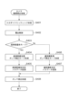
次に、撮像装置100におけるカメラマイコン111による、高輝度優先モード時のガンマ補正処理、メタデータ記録処理について、図4のフローチャートを参照しながら説明する。図4は、撮像装置100で行われるカメラ階調補正処理を示すフローチャートである。この処理は、撮像装置100をカメラモードで起動し、ライブビュー(LV)の撮影が開始されると繰り返し行われ、LV画像および動画記録開始後の記録用の撮像画像の双方に適用される処理である。なお、図4の処理は、図5で後述するカメラモード処理で行われるガンマ特性別のLV表示、動画記録の処理の部分に特化して詳細に説明したものである。   Next, gamma correction processing and metadata recording processing in the high brightness priority mode by the camera microcomputer 111 in the image pickup apparatus 100 will be described with reference to the flowchart in FIG. FIG. 4 is a flowchart showing the camera gradation correction processing performed by the image pickup apparatus 100. This process is repeated when the imaging apparatus 100 is started in the camera mode and the shooting of the live view (LV) is started, and is applied to both the LV image and the captured image for recording after the start of moving image recording. Is. The process of FIG. 4 is described in detail specifically for the LV display and moving image recording process for each gamma characteristic performed in the camera mode process described later with reference to FIG.

S401では、カメラマイコン111は、入力ダイナミックレンジを決定する。ここでの入力ダイナミックレンジは、カメラモードに含まれる複数の撮影モード毎に予め設定された所定値であるか、あるいは、輝度/色情報検出部110によって検出された輝度情報および色情報を基に算出された値である。S402では、カメラマイコン111は、輝度/色情報検出部110によって検出された輝度情報および色情報を基に露出制御を行う。   In S401, the camera microcomputer 111 determines the input dynamic range. The input dynamic range here is a predetermined value set in advance for each of a plurality of shooting modes included in the camera mode, or based on the brightness information and color information detected by the brightness / color information detection unit 110. This is the calculated value. In S402, the camera microcomputer 111 performs exposure control based on the brightness information and color information detected by the brightness / color information detection unit 110.

S403では、カメラマイコン111は、RAM111bに保持された撮影ガンマモードが高輝度優先モード(HPモード)かどうかを判断する。高輝度優先モードの場合、処理はS404に遷移し、ガンマ補正処理に用いるガンマ補正特性を高輝度優先用のガンマ補正カーブに決定する。S405では、カメラマイコン111は、撮影される画像に関して高輝度優先モードに対応したメタデータの記録を行う。ここで、記録されるメタデータは、高輝度優先モードを表すためのフラグ、入力ダイナミックレンジ、あらかじめ設定された表示輝度の基準値に対する倍率、ピーク輝度値、撮像装置100におけるガンマ形状情報やベースガンマなどである。   In step S403, the camera microcomputer 111 determines whether the shooting gamma mode held in the RAM 111b is the high brightness priority mode (HP mode). In the case of the high brightness priority mode, the process proceeds to S404, and the gamma correction characteristic used for the gamma correction process is determined to be the gamma correction curve for high brightness priority. In S405, the camera microcomputer 111 records the metadata corresponding to the high-luminance priority mode for the captured image. Here, the recorded metadata includes a flag for indicating the high-luminance priority mode, an input dynamic range, a magnification of a preset display luminance with respect to a reference value, a peak luminance value, gamma shape information and base gamma in the imaging apparatus 100. And so on.

一方、S403で高輝度優先モードではなくスタンダードモードと判定された場合、S406でカメラマイコン111は、ガンマ補正処理に用いるガンマ補正特性を通常撮影用のガンマ補正カーブに決定する。S407では、カメラマイコン111は、撮影される画像に関してスタンダードモードに対応したメタデータの記録を行う。ここで、記録するメタデータは、通常撮影モードを表すためのフラグ、入力ダイナミックレンジ、あらかじめ設定された表示輝度の基準値に対する倍率、ピーク輝度値、撮像装置100におけるガンマ形状情報やベースガンマなどである。   On the other hand, if it is determined in S403 that the standard mode is not the high-luminance priority mode, the camera microcomputer 111 determines the gamma correction characteristic used in the gamma correction process to be the gamma correction curve for normal shooting in S406. In S407, the camera microcomputer 111 records the metadata corresponding to the standard mode for the image to be captured. Here, the metadata to be recorded includes a flag for indicating a normal shooting mode, an input dynamic range, a magnification of a preset display luminance with respect to a reference value, a peak luminance value, gamma shape information in the imaging apparatus 100, base gamma, and the like. is there.

S408では、カメラマイコン111は、決定したガンマ補正特性に基づいてガンマ補正処理を行い、カメラの階調補正処理を終了する。カメラマイコン111は、カメラモードが終了するまで、カメラ階調補正処理を繰り返す。   In step S408, the camera microcomputer 111 performs gamma correction processing based on the determined gamma correction characteristics, and ends the camera gradation correction processing. The camera microcomputer 111 repeats the camera gradation correction processing until the camera mode ends.

<カメラモード処理>
図5に、撮像装置100におけるカメラモードの処理のフローチャートを示す。撮像装置100をカメラモードで起動すると、図5の処理を開始する。
<Camera mode processing>
FIG. 5 shows a flowchart of processing in the camera mode in the image pickup apparatus 100. When the image pickup apparatus 100 is started in the camera mode, the process of FIG. 5 is started.

S501では、カメラマイコン111は、RAM111bに保持している撮影ガンマモードが高輝度優先モード(HPモード)であるかどうかを判定する。撮影ガンマモードがHPモードであった場合には処理はS502へ遷移し、HPモードでなかった場合には処理はS503へ遷移する。   In step S501, the camera microcomputer 111 determines whether the shooting gamma mode held in the RAM 111b is the high-luminance priority mode (HP mode). If the shooting gamma mode is the HP mode, the process proceeds to S502, and if it is not the HP mode, the process proceeds to S503.

S502では、カメラマイコン111は、パネル輝度設定処理(図8のフローチャートにより後述)を行う。S503では、カメラマイコン111は、ROM111aに記憶している本体ディスプレイ116用のユーザー設定輝度を読み出し、ユーザー設定輝度で本体ディスプレイ116を表示する。なお、本体ディスプレイ116の設定輝度は、図6(d)を参照して後述するような輝度設定画面から設定される。また、ビューアシスト時にモニターガンマが変更されていれば、それを元に戻した通常のモニターガンマで表示する。以下、「ユーザー設定輝度で本体ディスプレイ116を表示する」と記載した場合は、モニターガンマは、ビューアシスト時に変更されたもの(後述のガンマ特性312)ではなく、通常のモニターガンマ(後述のガンマ特性304)を適用するものとする。S504では、カメラマイコン111は、イメージセンサ105で撮像され、信号処理部112において信号処理された映像データ(LV画像)を本体ディスプレイ116に表示する。図6(a)に、本体ディスプレイ116におけるLV画像600の表示例を示す。この画面は、HPモードであればS502のパネル輝度設定処理に応じた輝度で表示される。   In S502, the camera microcomputer 111 performs a panel brightness setting process (which will be described later with reference to the flowchart of FIG. 8). In S503, the camera microcomputer 111 reads the user-set brightness for the main body display 116 stored in the ROM 111a, and displays the main body display 116 at the user-set brightness. The set brightness of the main body display 116 is set from a brightness setting screen which will be described later with reference to FIG. Also, if the monitor gamma has been changed at the time of view assist, it is displayed in the normal monitor gamma that was restored. Hereinafter, when it is described that “the main unit display 116 is displayed at the user-set brightness”, the monitor gamma is not the one changed at the time of view assist (gamma characteristic 312 described later) but the normal monitor gamma (gamma characteristic described later). 304) is applied. In step S <b> 504, the camera microcomputer 111 displays video data (LV image) captured by the image sensor 105 and signal-processed by the signal processing unit 112 on the main body display 116. FIG. 6A shows a display example of the LV image 600 on the main body display 116. In the HP mode, this screen is displayed with the brightness according to the panel brightness setting process of S502.

S505では、カメラマイコン111は撮影ガンマモード切り替え画面を本体ディスプレイ116に表示させる指示があったか否かを判定する。切り替え画面を表示させる指示があった場合には処理はS506へ遷移し、そうでない場合には処理はS510へ遷移する。   In step S505, the camera microcomputer 111 determines whether or not there is an instruction to display the shooting gamma mode switching screen on the main body display 116. If there is an instruction to display the switching screen, the process proceeds to S506, and if not, the process proceeds to S510.

S506では、カメラマイコン111は図6(b)に示すような切り替え画面(撮影ガンマモード設定画面)を生成し、本体ディスプレイ116に表示する。撮影ガンマモード切り替え画面には、撮影ガンマモードとしてスタンダード(第1のモード)を選択するための選択肢601と、HPモード(第2のモード)を選択するための選択肢602が表示される。方向キーあるいはタッチ操作によって選択肢601と602うち何れかを選択すると、選択した選択肢に関する説明(ガイド)が表示される。図6(b)の例では、HPモードの選択肢602が選択されているため、HPモードに関する説明であるガイド603が表示されている。ガイド603には、「高輝度領域も圧縮せずに自然な階調で撮影します。外部モニターを明るめに設定することでより高精細な映像を楽しめます」と表示されている。すなわち、HPモードでどんな撮影ができるかの説明、及び、外部モニターの設定輝度を上げることをユーザに促す旨が表示されている。   In S506, the camera microcomputer 111 generates a switching screen (shooting gamma mode setting screen) as shown in FIG. 6B and displays it on the main body display 116. On the shooting gamma mode switching screen, an option 601 for selecting the standard (first mode) as the shooting gamma mode and an option 602 for selecting the HP mode (second mode) are displayed. When any one of the options 601 and 602 is selected by the direction key or the touch operation, an explanation (guide) regarding the selected option is displayed. In the example of FIG. 6B, since the HP mode option 602 is selected, a guide 603 that describes the HP mode is displayed. The guide 603 displays that "a high-luminance area is not compressed and is photographed with natural gradation. You can enjoy higher-definition images by setting a bright external monitor." That is, a description of what kind of shooting can be performed in the HP mode and a message prompting the user to increase the set brightness of the external monitor are displayed.

S507では、カメラマイコン111は切り替え画面にてユーザから何れかの選択肢(スタンダード/高輝度優先モード)が選択され決定する操作がされたか否かを判定する。選択肢601と602の何れかを選択した状態でセットボタンが押下されるか、あるいは閉じるアイコン604がタッチされると、選択している撮影ガンマモードで決定(設定)する。切り替え画面にてユーザから何れかの選択肢が選択され決定する操作がされた場合はS508へ遷移し、そうでない場合はS509へ遷移する。   In step S <b> 507, the camera microcomputer 111 determines whether or not any option (standard / high-brightness priority mode) has been selected and determined by the user on the switching screen. When the set button is pressed or the close icon 604 is touched while either of the options 601 and 602 is selected, the selected shooting gamma mode is determined (set). If the user selects any one of the options on the switching screen and performs an operation of determining, the process proceeds to S508, and if not, the process proceeds to S509.

S508では、カメラマイコン111は、S507でユーザから選択された撮影ガンマモードを決定し、決定された撮影ガンマモードをRAM111bに保持する。なお、決定された撮影ガンマモードは、ROM111aに記録されても良い。S509では、カメラマイコン111は、切り替え画面を閉じる操作があったか否かを判定する。閉じる操作があった場合には処理はS501へ遷移し、そうでない場合には処理はS507へ遷移する。切替画面を閉じる操作としては例えば、メニューボタンの押下がある。   In S508, the camera microcomputer 111 determines the shooting gamma mode selected by the user in S507, and holds the determined shooting gamma mode in the RAM 111b. The determined shooting gamma mode may be recorded in the ROM 111a. In S509, the camera microcomputer 111 determines whether or not there is an operation to close the switching screen. If there is a close operation, the process transitions to S501, and if not, the process transitions to S507. The operation of closing the switching screen includes, for example, pressing of a menu button.

一方、S505において撮影ガンマモード切り替え画面を表示させる指示ではなかった場合、処理はS510へ遷移し、カメラマイコン111は、メニュー画面を表示させる指示操作があったか否かを判定する。メニュー画面を表示させる指示操作としては、例えばメニューボタンの押下がある。メニュー画面を表示させる指示操作があった場合には処理はS511へ遷移し、そうでない場合には処理はS531へ遷移する。   On the other hand, if the instruction is not to display the shooting gamma mode switching screen in S505, the process proceeds to S510, and the camera microcomputer 111 determines whether or not there is an instruction operation to display the menu screen. The instruction operation for displaying the menu screen includes, for example, pressing a menu button. If there is an instruction operation to display the menu screen, the process proceeds to S511, and if not, the process proceeds to S531.

S511では、カメラマイコン111は、ROM111aに保持している本体ディスプレイ116用のユーザ設定輝度を読み出し、ユーザ設定輝度で本体ディスプレイ116にメニュー画面のトップメニューを表示する。すなわち、ビューアシスト設定がオンでHPモードであったことにより本体ディスプレイ116の輝度をユーザが設定したユーザ設定輝度よりも上げていた場合にも、メニュー画面に表示を切り替えたことに応じてユーザ設定輝度に戻す。これは、メニュー画面が撮像された画像ではない映像を表示する画面(撮像された画像が表示されない画面)であるためである。   In S511, the camera microcomputer 111 reads the user-set brightness for the main body display 116 stored in the ROM 111a, and displays the top menu of the menu screen on the main body display 116 at the user-set brightness. That is, even when the brightness of the main body display 116 is higher than the user-set brightness set by the user due to the view assist setting being on and in the HP mode, the user setting is switched according to the switching to the menu screen. Return to brightness. This is because the menu screen is a screen that displays a video that is not the captured image (a screen that does not display the captured image).

S512では、カメラマイコン111は、メニュー画面にある複数のメニュー項目のうち、ビューアシスト設定をするためのメニュー項目が選択されたかどうかを判定する。ビューアシスト設定のメニュー項目が選択された場合には処理はS513へ遷移し、そうでない場合には処理はS516へ遷移する。S513では、カメラマイコン111は、ビューアシスト設定画面を本体ディスプレイ116に表示し、ユーザから設定が選択されたか否かを判定する。   In S512, the camera microcomputer 111 determines whether a menu item for performing view assist setting has been selected from among the plurality of menu items on the menu screen. If the menu item for view assist setting is selected, the process proceeds to S513, and if not, the process proceeds to S516. In S513, the camera microcomputer 111 displays the view assist setting screen on the main body display 116 and determines whether or not the setting is selected by the user.

図6(c)に、本体ディスプレイ116でのビューアシスト設定画面の表示例を示す。ビューアシスト設定画面には、ビューアシストをオン(有効)とする選択肢611と、ビューアシストをオフ(無効)とする選択肢612が表示され、ユーザは何れかを選択して設定することができる。ビューアシストは、HPモードで撮影を行う際、及びHPモードで撮影された画像を再生して本体ディスプレイ116に表示する際の視認性に関するアシスト機能である。ビューアシストがオンに設定されていると、HPモードで撮影されたライブビュー画像を表示する際、及びHPモードで撮影された画像を再生して表示する際にディスプレイ116の輝度を自動的に上げる(自動的に輝度変更する)。ビューアシストは、カメラモード時だけでなく、再生モード等においてHPモードで記録された映像を再生表示する際にも適用される。   FIG. 6C shows a display example of the view assist setting screen on the main body display 116. On the view assist setting screen, an option 611 for turning on (enable) the view assist and an option 612 for turning off (invalid) the view assist are displayed, and the user can select and set one of them. The view assist is an assist function relating to visibility when shooting in the HP mode and when playing back an image shot in the HP mode and displaying it on the main body display 116. When the view assist is set to ON, the brightness of the display 116 is automatically increased when displaying a live view image captured in HP mode and when reproducing and displaying an image captured in HP mode. (The brightness is changed automatically). The view assist is applied not only in the camera mode but also in reproducing and displaying the image recorded in the HP mode in the reproducing mode or the like.

撮像時に適用するHPモードでの入力ガンマ特性は、ディスプレイに表示出力する際の出力ガンマ特性を合わせたシステムトータルでの階調特性を輝度リニアにすることで、暗部からハイライト部までの全域でより自然な階調性で表現するためのガンマ特性である。しかし、輝度リニアの階調特性の映像を表示すると、自然な階調性ではあるが、通常の入力ガンマ特性で記録された映像に比べて、中低輝度が暗くなってしまう。この中低輝度の見栄えを良くするためにビューアシストの機能が備えられており、ビューアシスト設定をオンとすることで、ディスプレイの表示輝度を上げ、中低輝度が暗くならないように表示することができる。なお、ビューアシスト設定がオフの場合はHPモードであっても表示輝度を自動的に上げることはしない。   The input gamma characteristic in the HP mode applied at the time of image pickup is made to be linear in the total gradation characteristic of the system including the output gamma characteristic when displaying and outputting on the display, so that the entire area from the dark portion to the highlight portion can be obtained. This is a gamma characteristic for expressing with more natural gradation. However, when an image having a gradation characteristic of linear brightness is displayed, the middle and low luminances are darker than those of an image recorded with a normal input gamma characteristic, although the gradation characteristic is natural. A view assist function is provided to improve the appearance of the middle and low brightness.By turning on the view assist setting, the display brightness of the display can be increased and the middle and low brightness can be displayed so that it does not become dark. it can. When the view assist setting is off, the display brightness is not automatically increased even in the HP mode.

十字キーの上下キーへの操作あるいは選択肢611または選択肢612へのタッチ操作によって選択肢611と選択肢612の何れかを選択する操作があると、処理はS514に遷移する。S514では、カメラマイコン111はS513で選択された設定(ビューアシストのオン/オフ)をRAM111bに保持する。なお、電源を切っても設定を保持するよう、ROM111bに記録しても良い。ビューアシストがオンからオフに設定変更された場合は、ビューアシストが解除される。すなわち、この後に表示されるHP動画は、ビューアシスト時に上げた本体ディスプレイ116の輝度を戻した状態、ビューアシスト時にモニターガンマが変更されていれば、それを元に戻した状態で表示される。S515では、カメラマイコン111はビューアシスト設定画面を閉じる操作(メニューボタンの押下また閉じるアイコン613へのタッチ操作)があったか否かを判定する。閉じる操作があった場合には処理はS501へ遷移し、そうでない場合には処理はS513へ遷移する。   If there is an operation of selecting one of the options 611 and 612 by operating the up and down keys of the cross key or touching the options 611 or 612, the process proceeds to S514. In S514, the camera microcomputer 111 holds the setting (view assist on / off) selected in S513 in the RAM 111b. Note that the settings may be stored in the ROM 111b so that the settings are retained even when the power is turned off. When the setting of the view assist is changed from on to off, the view assist is canceled. That is, the HP moving image displayed after this is displayed in a state in which the brightness of the main body display 116 raised during the view assist is returned, and in a state in which the monitor gamma is changed back if the monitor gamma is changed during the view assist. In step S515, the camera microcomputer 111 determines whether or not there has been an operation of closing the view assist setting screen (pressing the menu button or touching the close icon 613). If there is a close operation, the process transitions to S501, and if not, the process transitions to S513.

S516では、カメラマイコン111は、メニュー画面にある複数のメニュー項目のうち、信号処理部112において信号処理されたLV画像(映像データ)を背景に表示する設定画面に遷移するメニュー項目が選択されたかどうかを判定する。LV画像を背景に表示する設定画面に遷移するメニュー項目としては例えば、輝度設定、ズーム操作時の始点と終点に慣性をつけるか否かを選択するソフトズームコントロール、ズーム操作時のズーム速度を変更するズームスピードレベルがある。これらのメニュー項目に関しては、LV画像を背景に表示することで、設定の変化をよりユーザに把握しやすくさせることができる。LV画像を背景に表示する設定画面に遷移するメニュー項目が選択された場合には処理はS517へ遷移し、そうでない場合には処理はS521へ遷移する。   In S516, the camera microcomputer 111 selects, from among the plurality of menu items on the menu screen, a menu item that transits to a setting screen displaying the LV image (video data) processed by the signal processing unit 112 in the background. Determine whether Menu items for transitioning to the setting screen displaying the LV image in the background include, for example, brightness setting, soft zoom control for selecting whether to add inertia to the start point and end point during zoom operation, and change zoom speed during zoom operation. There is a zoom speed level to do. With respect to these menu items, displaying the LV image in the background makes it easier for the user to understand the change in the setting. If the menu item that causes a transition to the setting screen displaying the LV image in the background is selected, the process transitions to S517, and if not, the process transitions to S521.

S517では、カメラマイコン111はRAM111bに保持している撮影ガンマモードが高輝度優先モードであるかどうかを判定し、HPモードであった場合はS518へ遷移し、HPモードでなかった場合はS519へ遷移する。S518では、カメラマイコン111はパネル輝度設定処理(図8のフローチャートにより後述)を行う。S519では、カメラマイコン111は、S516で選択されたメニュー項目に応じた設定画面(LV画像を背景に表示する設定画面)を表示し、ユーザからの設定変更操作に応じた設定を行う。   In S517, the camera microcomputer 111 determines whether or not the shooting gamma mode held in the RAM 111b is the high-luminance priority mode. If it is the HP mode, the process proceeds to S518, and if it is not the HP mode, the process proceeds to S519. Transition. In step S518, the camera microcomputer 111 performs a panel brightness setting process (which will be described later with reference to the flowchart of FIG. 8). In S519, the camera microcomputer 111 displays a setting screen (setting screen displaying the LV image in the background) corresponding to the menu item selected in S516, and performs setting according to the setting change operation by the user.

図6(d)に、S516で選択されたメニュー項目に応じた設定画面の一例としての、輝度設定画面の表示例を示す。この画面は、メニュー画面の階層下における、HPモードで撮影された画像と共に表示可能な設定画面である。輝度設定画面では、本体ディスプレイ116の輝度として、2段階の設定値のうち何れかをユーザが選択して設定することができる。輝度設定画面には、LV画像623に重畳して、高輝度(HIGH)の選択肢621と通常(NORM)の選択肢622が表示される。ユーザが上下キーの操作あるいはタッチ操作によって何れかの選択肢を選択すると、選択した輝度に設定され、選択した輝度での表示が行われる。ユーザは、背景のLV画像623の見栄えを確認しながら、好みの輝度に設定することができる。設定された輝度はROM111aに記録され、HPモードでない場合の表示、HPモードであるがビューアシスト機能がオフとなっている場合の表示に適用される。ここで設定した輝度を、以下、「ユーザ設定輝度」と称する。本実施形態では、ユーザ設定輝度としてユーザが選択できる輝度は2段階であるが、3段階以上の多段階の中から選択できるようにしても良い。   FIG. 6D shows a display example of the brightness setting screen as an example of the setting screen corresponding to the menu item selected in S516. This screen is a setting screen that can be displayed together with an image taken in the HP mode under the menu screen. On the brightness setting screen, the user can select and set one of two setting values as the brightness of the main body display 116. On the brightness setting screen, a high brightness (HIGH) option 621 and a normal (NORM) option 622 are displayed so as to be superimposed on the LV image 623. When the user selects one of the options by operating the up and down keys or touching the operation, the selected brightness is set, and display is performed at the selected brightness. The user can set the desired brightness while checking the appearance of the background LV image 623. The set brightness is recorded in the ROM 111a and is applied to the display when the HP mode is not set and the display when the view assist function is off in the HP mode. The brightness set here is hereinafter referred to as "user set brightness". In the present embodiment, the user-selectable brightness has two levels of brightness, but the brightness may be selected from multiple levels of three or more levels.

S520では、カメラマイコン111は、S519で表示した設定画面を閉じる操作があったか否かを判定する。閉じる操作があった場合には処理はS501へ遷移し、閉じる操作がなかった場合には処理はS519へ遷移する。   In S520, the camera microcomputer 111 determines whether or not there is an operation of closing the setting screen displayed in S519. If the closing operation is performed, the process proceeds to S501, and if the closing operation is not performed, the process proceeds to S519.

S521では、カメラマイコン111はメニュー画面を閉じる操作があったか否かを判定する。閉じる操作があった場合には処理はS501へ遷移し、そうでない場合には処理はS522へ遷移する。S522では、カメラマイコン111は、メニュー画面において選択されたその他のメニュー項目に応じたその他の処理を行う。その他の処理(その他の設定処理)としては、例えば、撮像する動画の画質に関する設定や、AF方式に関する設定などがある。   In S521, the camera microcomputer 111 determines whether or not there is an operation of closing the menu screen. If there is a close operation, the process transitions to S501, and if not, the process transitions to S522. In S522, the camera microcomputer 111 performs other processing according to the other menu item selected on the menu screen. Other processing (other setting processing) includes, for example, setting regarding image quality of a moving image to be captured, setting regarding AF method, and the like.

S531では、カメラマイコン111は、動画用トリガスイッチ205が押されたか否かを判定する。押された場合はS532へ遷移し、そうでない場合はS538へ遷移する。S532では、カメラマイコン111は、RAM111bに保持している撮影ガンマモードがHPモードであるかどうかを判定する。HPモードと判定された場合には処理はS533へ遷移し、HPモードではないと判定された場合(スタンダードモードだった場合)には処理はS535へ遷移する。   In S531, the camera microcomputer 111 determines whether or not the moving image trigger switch 205 has been pressed. If it is pressed, the process proceeds to S532, and if not, the process proceeds to S538. In S532, the camera microcomputer 111 determines whether the shooting gamma mode stored in the RAM 111b is the HP mode. When it is determined that the mode is the HP mode, the process proceeds to S533, and when it is determined that the mode is not the HP mode (the standard mode), the process proceeds to S535.

S533では、カメラマイコン111は磁気テープ115、あるいはDVD117、あるいはメモリカード118に、イメージセンサ105で撮像され、信号処理部112から得られたHPモードでの映像を記録し始める。HPモードでの映像は、S404で説明した通り、高輝度優先用のガンマ補正カーブ(ガンマ特性303)を適用して得られた映像である。S534では、カメラマイコン111は、S533で記録している動画のメタデータとして、HPモードで撮影したことが識別可能な属性情報(以下、HP情報と称する)を付与する。HP情報は、動画ファイルのヘッダとして記録してもよいし、動画ファイルに関連付けられた管理ファイルに記録しても良い。   In step S533, the camera microcomputer 111 starts recording the image in the HP mode obtained by the image sensor 105 on the magnetic tape 115, the DVD 117, or the memory card 118 and obtained from the signal processing unit 112. The image in the HP mode is an image obtained by applying the gamma correction curve for high brightness priority (gamma characteristic 303) as described in S404. In step S534, the camera microcomputer 111 adds attribute information (hereinafter referred to as HP information) that can identify that the image was captured in the HP mode, as the metadata of the moving image recorded in step S533. The HP information may be recorded as a header of the moving image file or may be recorded in a management file associated with the moving image file.

S535では、カメラマイコン111は、磁気テープ115、あるいはDVD117、あるいはメモリカード118に、イメージセンサ105で撮像され、信号処理部112から得られた通常モードの映像を記録し始める。通常モード(スタンダードモード)での映像は、S406で説明した通り、通常撮影用のガンマ補正カーブ(ガンマ特性306)を適用して得られた映像である。   In S535, the camera microcomputer 111 starts recording the normal mode image captured by the image sensor 105 on the magnetic tape 115, the DVD 117, or the memory card 118 and obtained from the signal processing unit 112. The image in the normal mode (standard mode) is an image obtained by applying the gamma correction curve (gamma characteristic 306) for normal shooting, as described in S406.

S536では、カメラマイコン111は、動画用トリガスイッチ205が押されたかどうかを判定する。動画用トリガスイッチ205が押されたと判定された場合には処理はS537へ遷移し、カメラマイコン111は動画の記録を停止し、動画ファイルのクローズ処理を行う。他方、動画用トリガスイッチ205が押されていないと判定された場合には、処理はS536へ戻り、カメラマイコン111は動画の撮影記録を継続する。   In S536, the camera microcomputer 111 determines whether or not the moving image trigger switch 205 has been pressed. If it is determined that the moving image trigger switch 205 has been pressed, the process proceeds to S537, the camera microcomputer 111 stops the recording of the moving image, and closes the moving image file. On the other hand, if it is determined that the moving image trigger switch 205 is not pressed, the process returns to S536, and the camera microcomputer 111 continues shooting and recording of the moving image.

S538では、カメラマイコン111はモードダイヤル207が操作されたかどうかを判定する。操作されたと判定された場合には処理はS539へ遷移し、そうでない場合には処理はS505へ遷移する。S539では、カメラマイコン111は、S538で操作された結果が再生モードかどうかを判定する。再生モードであると判定された場合には処理はS540へ遷移し(再生モードに遷移し)し、カメラマイコン111は再生モード処理を実行する。S540の再生モード処理については図7を用いて後述する。他方、S539で再生モードでないと判定された場合には、カメラマイコン111は、電源をOFFして処理を終了する。   In S538, the camera microcomputer 111 determines whether the mode dial 207 has been operated. If it is determined that the operation has been performed, the process proceeds to S539, and if not, the process proceeds to S505. In S539, the camera microcomputer 111 determines whether the result of the operation in S538 is the reproduction mode. If it is determined to be in the reproduction mode, the process proceeds to S540 (transition to the reproduction mode), and the camera microcomputer 111 executes the reproduction mode process. The reproduction mode processing of S540 will be described later with reference to FIG. On the other hand, if it is determined in S539 that the playback mode is not set, the camera microcomputer 111 turns off the power and ends the process.

<再生モード処理>
図7に、撮像装置100における再生モードの処理のフローチャートを示す。撮像装置100を再生モードで起動したり、カメラモードから再生モードに遷移させたりすると、図7の処理を開始する。図7に示される処理は、図5のS540における再生モード処理の詳細である。
<Playback mode processing>
FIG. 7 shows a flowchart of processing in the reproduction mode in the image pickup apparatus 100. When the image pickup apparatus 100 is started in the reproduction mode, or when the camera mode is changed to the reproduction mode, the processing of FIG. 7 is started. The process shown in FIG. 7 is a detail of the reproduction mode process in S540 of FIG.

S701では、カメラマイコン111はROM111aに保持しているユーザ設定輝度を読み出し、ユーザ設定輝度で本体ディスプレイ116を表示する。S702では、カメラマイコン111は磁気テープ115、あるいはDVD117、あるいはメモリカード118に記憶されている画像と、各画像の属性情報を読み出し、画像のサムネイルを本体ディスプレイ116に一覧表示する。   In step S701, the camera microcomputer 111 reads the user-set brightness stored in the ROM 111a and displays the main body display 116 at the user-set brightness. In step S <b> 702, the camera microcomputer 111 reads the images stored on the magnetic tape 115, the DVD 117, or the memory card 118 and the attribute information of each image, and displays thumbnails of the images on the main body display 116 as a list.

図11(a)に、S702で本体ディスプレイ116に表示されるサムネイル一覧表示(インデックス表示、マルチ表示)の表示例を示す。サムネイル画像1101〜1108が表示され、これらのうち、HPモードで撮影された画像に対応するサムネイル画像には、HP動画であることを示すHPアイコン1109が付されている。なお、以下、HPモードで撮影された画像をHP動画と称する。また、通常モードで撮影された画像と通常モードで撮影されているライブビュー画像を総称して第1の種別の画像、HPモードで撮影された画像とHPモードで撮像されているライブビュー画像を総称して第2の種別の画像と称する。図示の例では、サムネイル画像1101、1102、1108によって示される動画がHP動画である。なお、読み出した各画像の属性情報にHP情報が付与されているか否かにより、HPモードで撮影された画像か否かが識別される。このサムネイル一覧表示では、HP動画のサムネイルが含まれていてもビューアシスト機能による輝度変更は行わない。   FIG. 11A shows a display example of the thumbnail list display (index display, multi-display) displayed on the main body display 116 in S702. Thumbnail images 1101 to 1108 are displayed, and a thumbnail image corresponding to an image shot in the HP mode is attached with an HP icon 1109 indicating that it is an HP moving image. In the following, an image taken in the HP mode will be referred to as an HP moving image. In addition, the image captured in the normal mode and the live view image captured in the normal mode are collectively referred to as the first type of image, the image captured in the HP mode and the live view image captured in the HP mode. The images of the second type are collectively referred to. In the illustrated example, the moving images indicated by the thumbnail images 1101, 1102, 1108 are HP moving images. It should be noted that whether or not the image captured in the HP mode is identified by whether or not the HP information is added to the read attribute information of each image. In this thumbnail list display, the brightness is not changed by the view assist function even if the thumbnail of the HP moving image is included.

S703では、カメラマイコン111は、サムネイル一覧に表示されたサムネイル画像の何れかを選択するユーザ操作があったか否か(動画の選択があったか否か)を判定する。何れかのサムネイル画像が選択された場合には処理はS704へ遷移し、そうでない場合にはS703の処理が繰り返される(サムネイル画像の選択を待つ)。S704では、カメラマイコン111はS703でユーザから選択されたサムネイル画像に対応する動画の再生表示を開始する。すなわち、カメラマイコン111は磁気テープ115、あるいはDVD117、あるいはメモリカード118に記憶されている再生すべき動画を読み出し、信号制御部112を制御して再生し、本体ディスプレイ116に再生した動画を表示する。あるいは、外部ディスプレイ120に再生した動画を表示するべく、外部I/F119から出力する。   In S703, the camera microcomputer 111 determines whether or not there is a user operation of selecting any of the thumbnail images displayed in the thumbnail list (whether or not a moving image has been selected). If any thumbnail image is selected, the process proceeds to S704, and if not, the process of S703 is repeated (waiting for selection of thumbnail image). In step S704, the camera microcomputer 111 starts reproduction and display of the moving image corresponding to the thumbnail image selected by the user in step S703. That is, the camera microcomputer 111 reads out a moving image to be reproduced stored in the magnetic tape 115, the DVD 117, or the memory card 118, controls the signal control unit 112 to reproduce the moving image, and displays the reproduced moving image on the main body display 116. . Alternatively, it is output from the external I / F 119 to display the reproduced moving image on the external display 120.

図11(b)、図11(c)に、本体ディスプレイ116における動画の再生中の表示例を示す。図11(b)は、ボタン表示「入」での表示例であり、再生動画1110に重畳して、HPアイコン1109とボタンアイコン1111が表示される。ボタンアイコン1111は動画の再生動作に関する各種操作(停止、早送り、早戻しを含む)を行うためのボタンアイコンであり、タッチ操作によってタッチされると、対応する処理が行われる。ボタン表示「入」と「切」とはユーザによる切り替えが可能である(S715、S716)。図11(c)は、ボタン表示「切」での表示例であり、再生動画1110が表示されているが、HPアイコン1109とボタンアイコン1111は表示されない。   11B and 11C show display examples during reproduction of a moving image on the main body display 116. FIG. 11B is a display example of the button display “ON”, in which the HP icon 1109 and the button icon 1111 are displayed in a superimposed manner on the reproduced moving image 1110. The button icon 1111 is a button icon for performing various operations (including stop, fast forward, and fast rewind) related to the moving image reproduction operation, and when touched by a touch operation, corresponding processing is performed. The button display "ON" and "OFF" can be switched by the user (S715, S716). FIG. 11C is a display example in which the button display is “off”. The playback moving image 1110 is displayed, but the HP icon 1109 and the button icon 1111 are not displayed.

S705では、カメラマイコン111は、再生している動画に付与されている属性情報を解析し、HP情報があるかを解析する。再生中の動画の属性情報にHP情報があった場合、すなわち、HP動画の再生中である場合には、処理はS706へ遷移し、そうでない場合(HP動画ではない動画を再生中である場合)には処理はS708へ遷移する。S706では、カメラマイコン111は、パネル輝度設定処理(図8のフローチャートにより後述)を行う。S707では、カメラマイコン111は、ガイド表示処理(図9のフローチャートにより後述)を行う。また、再生中の動画がHP動画ではない場合、S708において、カメラマイコン111は、ROM111aに保持しているユーザ設定輝度を読み出し、ユーザ設定輝度で本体ディスプレイ116を表示する。   In step S705, the camera microcomputer 111 analyzes the attribute information given to the moving image that is being reproduced, and analyzes whether there is HP information. If there is HP information in the attribute information of the moving image being played, that is, if the HP moving image is being played back, the process proceeds to S706, and if not (when a moving image that is not an HP moving image is being played back) ), The process transitions to S708. In step S706, the camera microcomputer 111 performs a panel brightness setting process (which will be described later with reference to the flowchart of FIG. 8). In S707, the camera microcomputer 111 performs guide display processing (which will be described later with reference to the flowchart of FIG. 9). If the moving image being reproduced is not the HP moving image, the camera microcomputer 111 reads out the user-set brightness stored in the ROM 111a and displays the main unit display 116 at the user-set brightness in step S708.

S709では、カメラマイコン111は、再生している動画が終端まできたかを判定する。終端まできたと判定された場合には処理はS710へ遷移し、そうでない場合には処理はS713へ遷移する。S710では、カメラマイコン111は、S707の処理でガイドを表示していた場合はガイドを非表示にする。S711では、カメラマイコン111は、磁気テープ115、あるいはDVD117、あるいはメモリカード118に記憶されている次の動画があるかどうかを判定する。次の動画があると判定された場合には処理はS712へ遷移し、次の動画がないと判定された場合には処理はS702へ遷移する。S712では、カメラマイコン111は、次の動画の再生を開始し、処理をS705へ戻す。   In step S709, the camera microcomputer 111 determines whether the moving image being played has reached the end. If it is determined that the end has been reached, the process transitions to S710, and if not, the process transitions to S713. In S710, the camera microcomputer 111 hides the guide if the guide was displayed in the process of S707. In S711, the camera microcomputer 111 determines whether or not there is the next moving image stored in the magnetic tape 115, the DVD 117, or the memory card 118. If it is determined that the next moving image exists, the process proceeds to S712, and if it is determined that the next moving image does not exist, the process proceeds to S702. In S712, the camera microcomputer 111 starts the reproduction of the next moving image, and returns the processing to S705.

S713では、カメラマイコン111は、再生している動画を停止させる停止操作がされたかどうかを判定し、停止操作がされた場合は動画の再生を停止してS714へ遷移し、そうでない場合はS715へ遷移する。S714では、カメラマイコン111は、停止画面処理(図10のフローチャートにより後述)を実行する。   In step S713, the camera microcomputer 111 determines whether or not a stop operation for stopping the moving image that is being played back is performed. If the stop operation is performed, the playback of the moving image is stopped and the process proceeds to step S714. If not, in step S715. Transition to. In S714, the camera microcomputer 111 executes stop screen processing (described later with reference to the flowchart of FIG. 10).

S715では、カメラマイコン111は、ユーザからのボタンの表示切り替えの指示操作がされたかどうかを判定する。切り替えが指示されたと判定された場合には処理はS716へ遷移し、そうでない場合には処理はS718へ遷移する。   In step S715, the camera microcomputer 111 determines whether or not the user has performed a button display switching instruction operation. If it is determined that the switching is instructed, the process proceeds to S716, and if not, the process proceeds to S718.

S716では、カメラマイコン111は、ボタン表示の「入」/「切」を切り替える。すなわち、ボタン表示「切」(図11(c))であった場合にボタン表示の切り替え指示があると、カメラマイコン111は、ボタン表示「入」に切り替え、図11(b)のようにボタンアイコン1111を表示する。この切り替えによって、表示中の動画がHP動画である場合にはHPアイコン1109も表示される。他方、ボタン表示「入」(図11(b))であった場合にボタン表示の切り替え指示があると、カメラマイコン111はボタン表示「切」に切り替え、図11(c)のようにボタンアイコン1111を非表示にする。また、表示中の動画がHP動画である場合には、ボタンアイコン1111を非表示にすることに伴って、HPアイコン1109も非表示にする。S717では、カメラマイコン111は、ガイド表示処理(図9のフローチャートにより後述)を行う。   In S716, the camera microcomputer 111 switches the button display between "ON" and "OFF". That is, when there is a button display switching instruction when the button display is “OFF” (FIG. 11C), the camera microcomputer 111 switches to the button display “ON” and the button is displayed as shown in FIG. 11B. The icon 1111 is displayed. By this switching, when the moving image being displayed is the HP moving image, the HP icon 1109 is also displayed. On the other hand, when the button display is “ON” (FIG. 11B) and there is an instruction to switch the button display, the camera microcomputer 111 switches to the button display “OFF” and the button icon is displayed as shown in FIG. 11C. Hide 1111. When the moving image being displayed is an HP moving image, the HP icon 1109 is also hidden along with the hiding of the button icon 1111. In S717, the camera microcomputer 111 performs guide display processing (described later with reference to the flowchart of FIG. 9).

S718では、カメラマイコン111は、モードダイヤル207が操作されたかどうかを判定する。操作された場合はS719へ遷移し、そうでない場合はS709へ遷移する。S719では、カメラマイコン111は、モードダイヤル207が操作された結果がカメラモードかどうかを判定する。カメラモードであった場合には処理はS720へ遷移し、カメラマイコン111は処理を再生モードからカメラモード(図5)へ切り替える。また、モードダイヤル207が操作された結果が電源オフであった場合には、カメラマイコン111は電源をOFFして処理を終了する。   In S718, the camera microcomputer 111 determines whether the mode dial 207 has been operated. If it is operated, the process proceeds to S719, and if not, the process proceeds to S709. In S719, the camera microcomputer 111 determines whether or not the result of operating the mode dial 207 is the camera mode. If it is the camera mode, the process proceeds to S720, and the camera microcomputer 111 switches the process from the reproduction mode to the camera mode (FIG. 5). If the result of operating the mode dial 207 is power off, the camera microcomputer 111 turns off the power and ends the process.

<パネル輝度設定処理>
図8は、図5のS502、S518,図7のS706で実行されるパネル輝度設定処理の詳細を示すフローチャートである。この処理は、HPモードあるいはHP動画であり、かつビューアシスト機能がオンである場合に、ユーザ設定輝度に関わらない高い輝度で本体ディスプレイ116を表示する処理である。
<Panel brightness setting process>
FIG. 8 is a flowchart showing details of the panel brightness setting processing executed in S502, S518 of FIG. 5 and S706 of FIG. This process is a process of displaying the main body display 116 at a high brightness irrespective of the user-set brightness when the view assist function is ON in the HP mode or the HP moving image.

S801では、カメラマイコン111は、RAM111bに保持しているビューアシスト設定の状態を読み出し、現在ビューアシスト設定がオンであるか否かを判断する。ビューアシストがオンであると判断した場合には処理はS802に遷移し、そうでなければ処理を終了する。S802では、カメラマイコン111は、ROM111aに保持している本体ディスプレイ116用のユーザ設定輝度の情報を読み出す。そしてユーザ設定輝度が所定の輝度設定以上(輝度が所定値以上に明るくなる輝度設定)であるか否かを判断する。本実施形態では、所定の輝度設定以上であるか否かとして、ユーザ設定輝度が高輝度(HIGH)であるか否かを判定する。輝度設定値が所定値以上(高輝度(HIGH))であれば処理はS804へ遷移し、そうでなければ(通常(NORM)である場合)処理はS803へ遷移する。   In S801, the camera microcomputer 111 reads the state of the view assist setting held in the RAM 111b, and determines whether or not the view assist setting is currently on. If it is determined that the view assist is on, the process proceeds to S802, and if not, the process ends. In step S802, the camera microcomputer 111 reads the user-set brightness information for the main body display 116 stored in the ROM 111a. Then, it is determined whether or not the user-set brightness is equal to or higher than a predetermined brightness setting (a brightness setting that makes the brightness brighter than a predetermined value). In the present embodiment, whether or not the user-set brightness is high brightness (HIGH) is determined as whether or not the brightness is equal to or higher than a predetermined brightness setting. If the brightness setting value is equal to or higher than the predetermined value (high brightness (HIGH)), the process proceeds to S804, and if not (normal (NORM)), the process proceeds to S803.

なお、本実施形態では、設定可能なユーザ輝度設定が高輝度(HIGH)と通常(NORM)であるため(図6(d))、高輝度(HIGH)であるか通常(NORM)であるかに応じて処理を分岐させるが、これに限られるものではなない。例えば、ユーザ設定輝度が3段階以上の設定輝度から設定できる場合には、S802の処理は、ユーザ設定輝度が、設定可能な輝度のうち最大値である場合に処理はS804に遷移し、そうでない場合には処理はS803に遷移するというようにしてもよい。また、たとえばユーザ設定輝度が5段階の設定輝度から設定できる場合、ユーザ設定輝度が明るい方から2段階目までの場合(1〜5の設定可能値のうちの4か5の場合)に処理がS804に遷移し、他の場合に処理がS803に遷移するようにしてもよい。   In the present embodiment, since the user brightness settings that can be set are high brightness (HIGH) and normal (NORM) (FIG. 6D), it is high brightness (HIGH) or normal (NORM). The process is branched according to, but is not limited to this. For example, if the user-set brightness can be set from three or more levels of set brightness, the process of S802 proceeds to S804 when the user-set brightness is the maximum value of the settable brightness, and is not so. In this case, the process may transition to S803. Further, for example, when the user-set brightness can be set from five levels of set brightness, or when the user-set brightness is from the brightest to the second level (in the case of 4 or 5 of the settable values 1 to 5), the processing The process may transit to S804, and the process may transit to S803 in other cases.

S803では、カメラマイコン111は、ユーザ設定輝度よりも輝度が高くなるように、本体ディスプレイ116の輝度を、予め決められたビューアシスト用の輝度にするよう制御する。これにより、HP動画がビューアシストONで再生されている場合には、例えばユーザ設定輝度が通常(NORM)に設定されていても、高輝度(HIGH)で表示されることになる。このとき、アイコン等の表示が明るくなりすぎると、本体ディスプレイ116に焼き付きが生じる可能性がある。そのため、アイコン等の、LV画像または再生画像以外の表示要素の本体ディスプレイ116上での表示輝度がビューアシスト設定オフ時の表示輝度と同じになるように、アイコン等の表示アイテムをビューアシスト設定オフ時よりも低い輝度で描画してもよい。すなわち、描画する明るさを暗くしてもよい。カメラマイコン111は、こうして表示輝度を変更すると、本処理を終える。   In step S <b> 803, the camera microcomputer 111 controls the brightness of the main body display 116 to a predetermined view assist brightness so that the brightness is higher than the user-set brightness. As a result, when the HP moving image is reproduced with the view assist ON, even if the user-set brightness is set to normal (NORM), it is displayed at high brightness (HIGH). At this time, if the display of the icon or the like becomes too bright, the main body display 116 may be burned. Therefore, the display items such as icons are turned off so that the display brightness of display elements other than the LV image or the reproduced image such as icons on the main body display 116 is the same as the display brightness when the view assist setting is turned off. You may draw with a lower brightness than that of the time. That is, the drawing brightness may be darkened. After changing the display brightness in this way, the camera microcomputer 111 ends this processing.

S804では、カメラマイコン111は、本体ディスプレイ116用のモニターガンマを、中間域での明るさをビューアシスト設定がオンにされていないときよりも明るくなるように変更する。ユーザ設定輝度が既に高輝度(HIGH)である(設定可能な最大輝度である)ため、これよりも明るい輝度で表示することができない(これ以上、本体ディスプレイ116の輝度を上げられない)。そこで、ビューアシスト設定時には、表示時のガンマ特性を変えることで、ビューアシスト設定がオンにされていないときよりも、階調特性307のように低輝度から中輝度の部分が明るくなるようにする。カメラマイコン111は、こうしてガンマ特性を変更すると、本処理を終える。   In S804, the camera microcomputer 111 changes the monitor gamma for the main body display 116 so that the brightness in the intermediate range is brighter than when the view assist setting is not turned on. Since the user-set brightness is already high brightness (highest brightness that can be set), it is not possible to display at a brightness higher than this (the brightness of the main body display 116 cannot be raised any more). Therefore, when the view assist setting is performed, the gamma characteristic at the time of display is changed so that the low-to-medium luminance portion as in the gradation characteristic 307 becomes brighter than when the view assist setting is not turned on. . The camera microcomputer 111 ends this processing when the gamma characteristic is changed in this way.

なお、S802では、ユーザ設定輝度を判定するので、ユーザ設定輝度が通常(NORM)に設定されている間はパネル輝度設定処理が実行されるたびにS803が実行される。同様に、ユーザ設定輝度が高輝度(HIGH)に設定されている間はパネル輝度設定処理が実行されるたびにS804が実行される。ビューアシスト設定中にユーザ設定輝度が高輝度から通常に変更されてS803が実行された場合には、カメラマイコン111は、S804で変更したモニターガンマを元に戻す。また、ビューアシスト設定中にユーザ設定輝度が通常から高輝度に変更されてS804が実行された場合には、カメラマイコン111は、モニターガンマをビューアシスト時の特性に変更する。   Since the user-set brightness is determined in S802, S803 is executed each time the panel brightness setting process is executed while the user-set brightness is set to normal (NORM). Similarly, while the user-set brightness is set to high brightness (HIGH), S804 is executed every time the panel brightness setting process is executed. When the user-set brightness is changed from high brightness to normal during the view assist setting and S <b> 803 is executed, the camera microcomputer 111 restores the monitor gamma changed in S <b> 804. When the user-set brightness is changed from normal to high brightness and S804 is executed during the view assist setting, the camera microcomputer 111 changes the monitor gamma to the view assist characteristic.

ビューアシストによる輝度変更について図3(c)を用いてさらに説明する。撮影装置のガンマ特性がHPモードにおけるガンマ特性303であった場合に、本体ディスプレイ116のガンマ特性304(第1の出力ガンマ特性)により表示を行うと、システムトータルの特性が輝度リニアな階調特性305となる。この状態で表示を行うと、HPモードにおいて被写体輝度の全域にわたって良好な再現性を得られる。しかしながら、通常モードの際の階調特性307に比べて、中輝度の部分が暗く見えてしまう傾向にある。ビューアシストがONになると、S803で本体ディスプレイ116の輝度が上昇し、システムトータルの特性が階調特性311のようになる。その結果、中輝度部分の輝度を上げることができ、視覚性が改善される。   The brightness change by the view assist will be further described with reference to FIG. When the gamma characteristic of the image capturing apparatus is the gamma characteristic 303 in the HP mode, when the display is performed by the gamma characteristic 304 (first output gamma characteristic) of the main body display 116, the system total characteristic is a luminance linear gradation characteristic. It becomes 305. When the display is performed in this state, good reproducibility can be obtained over the entire subject luminance in the HP mode. However, as compared with the gradation characteristic 307 in the normal mode, the middle luminance portion tends to appear dark. When the view assist is turned on, the brightness of the main body display 116 is increased in S803, and the system total characteristic becomes like the gradation characteristic 311. As a result, the brightness of the middle-brightness portion can be increased, and the visibility is improved.

なお、たとえば本体ディスプレイ116が液晶の場合は、バックライトの輝度をx(1より大きい)倍にすることで階調特性305を階調特性311に変更することができる。また、本体ディスプレイ116が有機ELの場合は、表示のガンマ特性をx(1より大きい)倍する(すなわち、有機ELの輝度を上げる)ことにより階調特性301を得ることができる。有機ELの輝度を上げた場合はすべての階調の輝度を同率で上げる。すなわち、最も明るい階調の輝度も上がる。さらに、ビューアシストをオンにした場合に、ユーザー設定輝度が高輝度(HIGH)であった場合には、本体ディスプレイ116の表示時のガンマ特性としてガンマ特性312を採用することにより、システムトータルの特性が階調特性313のようになる。ガンマ特性312(第2の出力ガンマ特性)は、ガンマ特性304よりも中間〜低輝度側を明るく表示するガンマ特性である。これにより、さらに中間部の見栄えが向上する。表示装置のガンマ特性312を適用した場合の階調特性313の最も明るい階調の輝度は階調特性301と同じであるが、低〜中間部分の階調が持ち上がっており、この部分の見栄えが向上する。   Note that, for example, when the main body display 116 is a liquid crystal, the gradation characteristic 305 can be changed to the gradation characteristic 311 by multiplying the brightness of the backlight by x (greater than 1). When the main body display 116 is an organic EL, the gradation characteristic 301 can be obtained by multiplying the display gamma characteristic by x (greater than 1) (that is, increasing the luminance of the organic EL). When the brightness of the organic EL is increased, the brightness of all gradations is increased at the same rate. That is, the brightness of the brightest gradation also increases. Further, when the user-set brightness is high brightness (HIGH) when the view assist is turned on, by adopting the gamma property 312 as the gamma property at the time of displaying on the main body display 116, the system total property is obtained. Becomes a gradation characteristic 313. The gamma characteristic 312 (second output gamma characteristic) is a gamma characteristic in which the intermediate to low luminance side is displayed brighter than the gamma characteristic 304. As a result, the appearance of the middle portion is further improved. The brightness of the brightest gradation of the gradation characteristic 313 when the gamma characteristic 312 of the display device is applied is the same as that of the gradation characteristic 301, but the gradation in the low to middle portions is raised, and this portion looks good. improves.

<ガイド表示処理>
図9は、図7のS707、S717で実行されるガイド表示処理の詳細を示すフローチャートである。ガイド表示処理は、HP動画を再生する場合であって、外部I/F119に外部ディスプレイ120が接続されている場合に、ユーザに外部ディスプレイ120の輝度の変更(輝度を上げること)を促すガイドを表示する処理である。
<Guide display processing>
FIG. 9 is a flowchart showing details of the guide display processing executed in S707 and S717 of FIG. The guide display process is a case of reproducing an HP moving image, and when the external display 120 is connected to the external I / F 119, a guide that prompts the user to change the brightness of the external display 120 (increase the brightness). This is the process of displaying.

S901では、カメラマイコン111は、外部I/F119に外部ディスプレイ120が接続されており、外部ディスプレイ120に映像出力されているか否かを判定する。外部ディスプレイ120に映像出力されている場合には処理はステップS903へ遷移し、そうでなければ処理はS902へ遷移する。S902では、カメラマイコン111は、RAM111bに保持しているガイド表示済みフラグをオフにする。このガイド表示済みフラグは、一度ガイド表示を行った後は、外部ディスプレイ120の接続が解除されるまで再度ガイド表示が行われることがないように、ガイド表示を既に行ったか否かを記憶しておくためのものである。   In step S <b> 901, the camera microcomputer 111 determines whether the external display 120 is connected to the external I / F 119 and video is output to the external display 120. If the image is output to the external display 120, the process transitions to step S903, and if not, the process transitions to S902. In step S902, the camera microcomputer 111 turns off the guide-displayed flag held in the RAM 111b. This guide-displayed flag stores whether or not the guide display has already been performed so that once the guide display is performed, the guide display is not performed again until the external display 120 is disconnected. It is for storing.

S903では、カメラマイコン111は、ボタン表示の設定が「入」であるか否かを判定する。すなわち、ボタンアイコン1111が表示された状態か否かの判定である。ボタン表示が「切」である場合には処理はS904へ遷移し、ボタン表示が「入」であれば、ここで処理は終了となる。なお、ボタン表示が「入」である場合に処理を終了とするのは、ガイド表示によりボタンアイコンが隠れてしまうことにより、ユーザが動画の再生、停止等の動作を指示することが出来なくなるのを防ぐためである。   In step S903, the camera microcomputer 111 determines whether the button display setting is “ON”. That is, it is a determination as to whether or not the button icon 1111 is displayed. If the button display is "OFF", the process proceeds to S904, and if the button display is "ON", the process ends here. When the button display is "ON", the processing is terminated because the button icon is hidden by the guide display, and the user cannot instruct the operation such as the reproduction and stop of the moving image. This is to prevent

S904では、カメラマイコン111はRAM111bに保持しているガイド表示済みフラグがオフであるか否かを確認する。ガイド表示済みフラグがオフである場合には、処理はS905へ遷移し、そうでなければ、ここで処理は終了となる。S905では、カメラマイコン111は外部I/F119から出力される映像信号と、本体ディスプレイ116に表示される映像信号に、外部表示装置の輝度の変更を促すガイド表示を重畳する。また、カメラマイコン111はRAM111bに保持しているガイド表示済みフラグをオンにする。ガイド表示は、S905で表示が開始されてから所定時間が経過すると自動的に消去される。   In S904, the camera microcomputer 111 confirms whether or not the guide display completed flag held in the RAM 111b is off. If the guide-displayed flag is off, the process proceeds to S905, and if not, the process ends here. In step S <b> 905, the camera microcomputer 111 superimposes a guide display for prompting a change in the brightness of the external display device on the video signal output from the external I / F 119 and the video signal displayed on the main body display 116. Further, the camera microcomputer 111 turns on the guide-displayed flag held in the RAM 111b. The guide display is automatically erased when a predetermined time has elapsed since the display was started in S905.

図11(d)に、S905での、本体ディスプレイ116及び外部ディスプレイ120におけるガイド表示の表示例を示す。HP動画である再生動画1110に重畳して、外部モニターを明るめの設定にして再生することを促すガイド表示1120が表示されている。ユーザはこのガイド表示1120を見ることで、外部ディスプレイ120の輝度設定を変更して輝度を上げる操作を自ら行うとよいことに気付くことができる。カメラマイコン111は、外部ディスプレイ120が接続されてから初めてHP動画を再生し始めた場合、または、HP動画を再生している途中で外部ディスプレイ120が接続された場合、にガイド表示1120の表示を開始する。そして、カメラマイコン111は、ガイド表示1120を表示してから所定時間後にガイド表示1120を非表示として、再生動画1110だけの表示とする。   FIG. 11D shows a display example of the guide display on the main body display 116 and the external display 120 in S905. A guide display 1120 is displayed so as to be superimposed on the reproduced moving image 1110 which is an HP moving image and to perform reproduction with the external monitor set to a lighter setting. By looking at this guide display 1120, the user can recognize that it is desirable to change the brightness setting of the external display 120 and increase the brightness by himself. The camera microcomputer 111 displays the guide display 1120 when the HP moving image is started to be reproduced for the first time after the external display 120 is connected, or when the external display 120 is connected during the reproduction of the HP moving image. Start. Then, the camera microcomputer 111 hides the guide display 1120 a predetermined time after displaying the guide display 1120, and displays only the reproduced moving image 1110.

なお、ガイド表示1120は、外部I/F119に接続される外部ディスプレイ120のみに関するものである。従って、本体ディスプレイ116に表示することなく、外部I/F119から出力される映像信号のみにガイド表示1120が表示されるように制御してもよい。また、外部I/F119から出力する画像に対する文字表示等の表示アイテムの重畳の許可・不許可を設定することが出来る。そして、重畳が不許可に設定されていても、このガイド表示に限っては重畳を行う(HP動画にガイド表示を重畳して出力する)ように制御してもよい。こうすることで、ユーザが適切でない外部表示装置の輝度設定(HP動画の階調特性の低輝度から中輝度の部分が通常ガンマで撮影したものより暗く見えてしまう輝度設定)のまま動画を視聴する可能性を少なくすることが出来る。   The guide display 1120 relates only to the external display 120 connected to the external I / F 119. Therefore, the guide display 1120 may be controlled to be displayed only on the video signal output from the external I / F 119 without displaying it on the main body display 116. Further, it is possible to set permission / non-permission of superimposing a display item such as a character display on an image output from the external I / F 119. Then, even if the superimposition is set to be not permitted, the control may be performed so that the superimposition is performed only for this guide display (the guide display is superposed on the HP moving image and output). By doing so, the user watches the video while the brightness setting of the external display device is not appropriate (the brightness setting in which the low-to-medium brightness part of the gradation characteristics of the HP video looks darker than that normally captured with gamma). It is possible to reduce the possibility of doing.

なお、上述した図9のガイド表示処理は、図7のS707(すなわち、各動画の再生の開始時)と、S717(すなわち、ボタン表示の切替後)に行う例を説明したが、これに限るものではない。外部I/F119に外部ディスプレイ120が接続されたことを検知したタイミングで行っても良い。すなわち、動画の再生の途中で、外部I/F119に外部ディスプレイ120が接続されたことを検知すると、カメラマイコン111は、その時点で再生している動画がHP動画であるか否かを判定する。そして、HP動画である場合には、外部表示装置の輝度の変更を促すガイド表示を外部I/F119から外部ディスプレイ120に向けて出力する。また、複数の動画を連続して再生する場合、再生すべき複数の動画にHP動画が含まれていれば、最初の動画の再生前に外部表示装置の輝度の変更を促すガイド表示を外部I/F119から出力(動画に重畳して出力)しても良い。例えば、プレイリストに基づいて1番目からN番目までのN個の動画を連続して再生する指示があった場合に、カメラマイコンン111は、そのN個の動画の中に少なくとも1つのHP動画が含まれているか否かを判定する。そして、少なくとも1つのHP動画が含まれていた場合には、1番目に再生する動画がHP動画でなくとも、1番目の動画の再生開始時に、図9のガイド表示処理を行う。そして、外部出力中である場合には外部表示装置の輝度の変更を促すガイド表示を外部I/F119から出力する。或いは、最初の動画の再生時ではなく、動画のリストに含まれるHP動画の再生が開始するまでの時間を計算し、その時間が所定の時間以下となった場合にガイドを表示するようにしてもよい。すなわち、カメラマイコン111は、複数の動画を連続して再生して外部I/F119から出力する際に、通常の動画を再生している時でも、HP動画の再生が開始されるまでの時間が所定の時間となった場合に、ガイド表示を外部I/F119から出力する。   Although the guide display process of FIG. 9 described above is performed in S707 of FIG. 7 (that is, at the start of playback of each moving image) and S717 (that is, after switching the button display), the example is not limited to this. Not a thing. It may be performed at the timing when it is detected that the external display 120 is connected to the external I / F 119. That is, when it is detected that the external display 120 is connected to the external I / F 119 during the reproduction of the moving image, the camera microcomputer 111 determines whether or not the moving image currently being reproduced is the HP moving image. . Then, in the case of the HP moving image, a guide display for prompting a change in the brightness of the external display device is output from the external I / F 119 to the external display 120. Further, when a plurality of moving images are continuously played back, if a plurality of moving images to be played back include an HP moving image, a guide display for prompting a change in the brightness of the external display device before the first moving image is displayed on the external I. You may output from / F119 (it superimposes on a moving image and outputs). For example, when there is an instruction to continuously play N moving pictures from the 1st to the Nth based on the playlist, the camera microcomputer 111 causes at least one HP moving picture among the N moving pictures. It is determined whether or not is included. Then, if at least one HP moving image is included, the guide display process of FIG. 9 is performed at the start of reproduction of the first moving image even if the first moving image is not the HP moving image. Then, when the external output is being performed, the external I / F 119 outputs a guide display prompting to change the brightness of the external display device. Alternatively, the time until the playback of the HP video included in the video list is calculated, not when the first video is played, and the guide is displayed when the time is less than the predetermined time. Good. That is, when the camera microcomputer 111 continuously reproduces a plurality of moving images and outputs them from the external I / F 119, the time until the reproduction of the HP moving image is started even when the normal moving image is being reproduced. When the predetermined time is reached, the guide display is output from the external I / F 119.

また、動画の再生時だけでなく、動画の一覧表示等をする画面で、HP動画を示すサムネイルやファイル名等が表示された場合に、ガイド表示1120を表示するようにしてもよい。また、この場合、単にHP動画を示すサムネイルやファイル名等が表示された場合にガイド表示を行うだけでなく、HP動画を示すサムネイルやファイル名、アイコン1109等に選択カーソル等の表示が重なったときにガイド表示を実行するようにしてもよい。すなわち、カメラマイコン111は、通常の画像とHP動画を含む複数の画像の一覧画面を出力している際に、HP動画を特定する情報あるいはHP動画であることを示す表示アイテム(アイコン1109)が選択された場合に、ガイドを出力する。HP動画を特定する情報はサムネイルやファイル名などである。   Further, the guide display 1120 may be displayed not only during playback of a moving image but also when a thumbnail or file name indicating an HP moving image is displayed on a screen for displaying a list of moving images. Further, in this case, not only the guide display is performed when the thumbnail or the file name indicating the HP moving image is simply displayed, but also the display of the selection cursor or the like is superimposed on the thumbnail or the file name indicating the HP moving image, the icon 1109, or the like. The guide display may be executed from time to time. That is, when the camera microcomputer 111 outputs a list screen of a plurality of images including a normal image and an HP moving image, information specifying the HP moving image or a display item (icon 1109) indicating the HP moving image is displayed. Outputs a guide when selected. The information specifying the HP moving image is a thumbnail, a file name, or the like.

また、図9の例では、ボタン表示がされていない場合(S902No)の場合にガイド表示を実行する例を説明したが、ボタン表示がされている場合にもガイド表示を行うものとしても良い。また、外部I/F119から、外部ディスプレイ120で設定されている輝度設定の情報を取得し、外部ディスプレイ120の輝度設定が所定の設定値以上に明るい設定には、ガイド表示を行わないようにしても良い。   Further, in the example of FIG. 9, the example in which the guide display is executed when the button display is not performed (S902 No) has been described, but the guide display may be performed even when the button display is performed. Further, the information of the brightness setting set on the external display 120 is acquired from the external I / F 119, and the guide display is not performed when the brightness setting of the external display 120 is brighter than a predetermined set value. Is also good.

<停止中画面処理>
図10は、図7のS714で実行される停止中画面処理の詳細を示すフローチャートである。停止中画面処理は、再生モード処理で動画を再生していた状態から動画の再生が停止されると実行される処理である。
<Screen processing during stop>
FIG. 10 is a flow chart showing the details of the in-stop screen process executed in S714 of FIG. The stopped screen process is a process executed when the reproduction of the moving image is stopped from the state where the moving image is being reproduced in the reproduction mode process.

S1001では、カメラマイコン111は、ボタン付き停止画面を本体ディスプレイ116に表示する。すなわち、動画再生中のボタン表示設定が「入」であるか「切」であるかに関わらず、停止すると最初はボタンアイコンが表示される。図11(e)に、このときの表示例を示す。カメラマイコン111は停止中の動画1130に重畳して、ボタンアイコン群1131を表示する。このとき、カメラマイコン111は、停止中の動画がHP動画である場合には、HPアイコン1109も表示する。   In step S1001, the camera microcomputer 111 displays a stop screen with buttons on the main body display 116. That is, regardless of whether the button display setting during video reproduction is “ON” or “OFF”, when stopped, the button icon is initially displayed. FIG. 11E shows a display example at this time. The camera microcomputer 111 displays the button icon group 1131 by superimposing it on the stopped moving image 1130. At this time, when the stopped moving image is the HP moving image, the camera microcomputer 111 also displays the HP icon 1109.

S1002では、カメラマイコン111は、ユーザが操作スイッチ群208への操作あるいはボタンアイコンへのタッチ操作によりシーン送り操作(次の動画を選択する操作)を行ったかどうかを判定する。シーン送り操作が行われたと判定された場合には処理はS1003へ遷移し、そうでない場合には処理はS1009へ遷移する。S1003では、カメラマイコン111は、磁気テープ115/DVD117/メモリカード118から次の動画シーンを読み出し、デコード処理を行い、動画シーンのメタデータ(属性情報)の解析を行う。   In step S1002, the camera microcomputer 111 determines whether the user has performed a scene advance operation (operation to select the next moving image) by operating the operation switch group 208 or touching a button icon. If it is determined that the scene advance operation has been performed, the process proceeds to S1003, and if not, the process proceeds to S1009. In step S1003, the camera microcomputer 111 reads the next moving image scene from the magnetic tape 115 / DVD 117 / memory card 118, performs decoding processing, and analyzes the metadata (attribute information) of the moving image scene.

S1004では、カメラマイコン111は、S1003で解析したメタデータから、次の動画シーンがHP動画であるか否かを判定する。すなわち、次のシーンの動画の属性情報にHP情報が付与されているか否かを判定する。HP動画であると判定された場合には処理はS1005に遷移し、そうでないと判定された場合には処理はS1007へ遷移する。   In S1004, the camera microcomputer 111 determines whether the next moving image scene is an HP moving image from the metadata analyzed in S1003. That is, it is determined whether the HP information is added to the attribute information of the moving image of the next scene. If it is determined that the moving image is an HP moving image, the process proceeds to S1005, and if not, the process proceeds to S1007.

S1005では、カメラマイコン111は、図8で前述したパネル輝度設定処理を行う。S1006では、カメラマイコン111は、図9で前述したガイド表示処理を行う。S1007では、カメラマイコン111は、RAM111bまたはROM111aに記録されたユーザ設定輝度を読み出し、本体ディスプレイ116の輝度を読み出したユーザ設定輝度とする。この時、ユーザ設定輝度が通常(NORM)で、かつ、前のシーンの動画がHP動画であり、ビューアシスト機能がオンだった場合には、次の通常動画に遷移したことに応じて本体ディスプレイ116の輝度が変更され、自動的に下げられることとなる。S1008では、カメラマイコン111は、S1003でデコードされた次のシーンの動画のフレームをボタン表示付きの停止画面として本体ディスプレイ116に表示する。   In step S1005, the camera microcomputer 111 performs the panel brightness setting process described above with reference to FIG. In S1006, the camera microcomputer 111 performs the guide display process described above with reference to FIG. In step S1007, the camera microcomputer 111 reads the user-set brightness recorded in the RAM 111b or the ROM 111a, and sets the brightness of the main body display 116 as the read user-set brightness. At this time, when the user-set brightness is normal (NORM), the moving image of the previous scene is the HP moving image, and the view assist function is on, the main unit display is displayed in response to the transition to the next normal moving image. The brightness of 116 will be changed and automatically lowered. In step S1008, the camera microcomputer 111 displays the frame of the moving image of the next scene decoded in step S1003 on the main body display 116 as a stop screen with button display.

S1009では、カメラマイコン111は、ユーザが操作スイッチ群208への操作またはタッチ操作により、表示している動画の再生指示操作を行ったかどうかを判定する。ユーザが再生指示操作を行ったと判定した場合には処理は図7のS704へ遷移し、カメラマイコン111は、シーン送り操作により選択された動画の再生を開始する。再生指示操作が行われていない場合には、処理はS1010へ遷移する。   In step S1009, the camera microcomputer 111 determines whether the user has performed a playback instruction operation of the displayed moving image by operating the operation switch group 208 or a touch operation. If it is determined that the user has performed the reproduction instruction operation, the process proceeds to S704 in FIG. 7, and the camera microcomputer 111 starts reproduction of the moving image selected by the scene advance operation. If the reproduction instruction operation has not been performed, the process proceeds to S1010.

S1010では、カメラマイコン111は、ユーザが操作スイッチ群208への操作またはタッチ操作によりメニューを開く操作を行ったかどうかを判定する。ユーザがメニューを開く操作を行ったと判定した場合には処理はS1011へ遷移し、そうでない場合には処理はS1021へ遷移する。   In step S1010, the camera microcomputer 111 determines whether the user has performed an operation to open a menu by operating the operation switch group 208 or a touch operation. If it is determined that the user has performed the operation of opening the menu, the process proceeds to S1011; otherwise, the process proceeds to S1021.

S1011では、カメラマイコン111は、RAM111bまたはROM111aから、メニューで設定されていたユーザ設定輝度を読み出し、読み出したユーザ設定輝度になるよう、本体ディスプレイ116の輝度を調整する。また、カメラマイコン111は、本体ディスプレイ116にメニューのトップ階層(トップメニュー)を表示する。   In step S1011, the camera microcomputer 111 reads the user-set brightness set in the menu from the RAM 111b or the ROM 111a, and adjusts the brightness of the main body display 116 so that the read user-set brightness is obtained. Further, the camera microcomputer 111 displays the top layer of the menu (top menu) on the main body display 116.

S1012では、カメラマイコン111は、ユーザが操作スイッチ群208への操作またはタッチ操作により、メニュー画面に含まれる複数のメニュー項目のうち、輝度設定メニューの項目を選択したかどうかを判定する。輝度設定メニューは、本体ディスプレイ116の輝度(ユーザ設定輝度)を設定するメニューであり、また、輝度設定メニュー表示中は動画も一時停止状態で表示される。輝度設定メニューを選択したと判定された場合には処理はS1013へ遷移し、そうでない場合には処理はS1019へ遷移する。   In step S1012, the camera microcomputer 111 determines whether the user has selected a brightness setting menu item from a plurality of menu items included in the menu screen by operating or touching the operation switch group 208. The brightness setting menu is a menu for setting the brightness (user-set brightness) of the main body display 116, and a moving image is also displayed in a pause state while the brightness setting menu is displayed. If it is determined that the brightness setting menu is selected, the process transitions to S1013, and if not, the process transitions to S1019.

S1013では、カメラマイコン111は一時停止されている動画の属性情報によりHP動画かどうか(HP情報が付与されているか否か)を判定する。HP動画と判定された場合には処理はS1014に遷移し、そうでない場合には処理はS1015へ遷移する。S1014は、カメラマイコン111は、図8で説明したパネル輝度設定処理を行う。   In step S <b> 1013, the camera microcomputer 111 determines whether it is an HP moving image (whether or not HP information is added) based on the attribute information of the temporarily stopped moving image. If it is determined to be an HP moving image, the process proceeds to S1014, and if not, the process proceeds to S1015. In step S1014, the camera microcomputer 111 performs the panel brightness setting process described in FIG.

S1015では、カメラマイコン111は、輝度設定画面を本体ディスプレイ116へ表示する。輝度設定画面は、図6(d)で説明したものと同様の画面である。ただし、背景に表示される画像はLV画像ではなく、直前に表示していた再生動画の停止中の映像である。S1016では、カメラマイコン111は、ユーザが操作スイッチ群208への操作またはタッチ操作により輝度設定を変更したかどうか(設定されているユーザ設定輝度と異なる輝度設定の選択肢が選択されたか)を判定する。これは、図6(d)の表示例と図5のS519で例示した処理と同様である。輝度設定を変更したと判定された場合には処理はS1017へ遷移し、変更していないと判定された場合には処理はS1018へ遷移する。   In S1015, the camera microcomputer 111 displays the brightness setting screen on the main body display 116. The brightness setting screen is the same screen as that described with reference to FIG. However, the image displayed in the background is not the LV image but the stopped video of the reproduced moving image displayed immediately before. In step S1016, the camera microcomputer 111 determines whether the user has changed the brightness setting by operating the operation switch group 208 or a touch operation (whether a brightness setting option different from the set user setting brightness has been selected). . This is the same as the display example of FIG. 6D and the processing illustrated in S519 of FIG. If it is determined that the brightness setting has been changed, the process proceeds to S1017, and if it is determined that the brightness setting has not been changed, the process proceeds to S1018.

S1017では、カメラマイコン111は、設定された輝度をユーザ設定輝度としてROM111aに記憶するとともに、設定された輝度となるように本体ディスプレイ116の輝度を変更する。この時、輝度設定画面には背景に再生動画の停止中の映像が表示されているため、ユーザは映像の見栄えを確認しながら好みの輝度に設定することができる。なお、輝度を変更した場合にS1014のパネル輝度設定処理はやり直さないものとする。これは、HP動画でありビューアシスト機能がオンとなっていることが要因でユーザ設定輝度に関わらず高輝度(HIGH)で表示されていた場合に、通常輝度(NORM)に変更してもパネル輝度設定処理により表示輝度が下がらないためである。このように通常輝度(NORM)への変更に応じて輝度が下がらないと、輝度を変更できたことをユーザにフィードバックできない。   In S1017, the camera microcomputer 111 stores the set brightness as the user-set brightness in the ROM 111a, and changes the brightness of the main body display 116 so that the brightness becomes the set brightness. At this time, since the video in which the reproduced moving image is stopped is displayed in the background on the brightness setting screen, the user can set the desired brightness while checking the appearance of the video. Note that the panel brightness setting process of S1014 is not performed again when the brightness is changed. This is an HP moving image, and when the view assist function is turned on, if the display is high brightness (HIGH) regardless of the brightness set by the user, even if the brightness is changed to normal brightness (NORM), the panel is displayed. This is because the display brightness does not decrease due to the brightness setting process. As described above, unless the brightness is reduced in accordance with the change to the normal brightness (NORM), it is not possible to feed back to the user that the brightness has been changed.

ただし、表示している画像がHP動画であり、通常(NORM)から高輝度(HIGH)に変更したのであれば、S1014のパネル輝度設定処理をやり直すものとしてもよい。このようにすれば、HP動画でビューアシストがオンであれば、適用される表示ガンマ(モニターガンマ)が変更されるため、HP動画の見栄えが良くなる。また、ユーザ設定輝度の変更に応じて表示状態が変わるため、ユーザに設定が変更されたことを認識させることもできる。   However, if the displayed image is an HP moving image and normal (NORM) is changed to high brightness (HIGH), the panel brightness setting process of S1014 may be redone. In this way, when the view assist is turned on in the HP moving image, the applied display gamma (monitor gamma) is changed, so that the HP moving image looks good. Moreover, since the display state changes according to the change in the user-set brightness, it is possible to let the user recognize that the setting has been changed.

S1018では、カメラマイコン111は、ユーザが操作スイッチ群208への操作またはタッチ操作により輝度設定画面を抜ける操作を行ったかどうかを判定する。設定画面を抜ける操作が行われたと判定された場合には処理はS1011へ遷移し、そうでない場合には処理はS1016へ遷移する。   In step S1018, the camera microcomputer 111 determines whether the user has operated the operation switch group 208 or a touch operation to exit the brightness setting screen. If it is determined that the operation for exiting the setting screen is performed, the process proceeds to S1011; otherwise, the process proceeds to S1016.

S1019では、カメラマイコン111は、ユーザが操作スイッチ群208への操作またはタッチ操作によりメニュー画面を抜ける操作を行ったかどうかを判定する。メニュー画面を抜ける操作が行われたと判定された場合には処理はS1001へ遷移し、そうでない場合には処理はS1020へ遷移する。S1020では、カメラマイコン111は、選択されたその他のメニュー項目に応じたその他のメニュー処理を行う。   In step S1019, the camera microcomputer 111 determines whether the user has performed an operation to exit the menu screen by operating the operation switch group 208 or a touch operation. If it is determined that the operation for exiting the menu screen is performed, the process proceeds to S1001, and if not, the process proceeds to S1020. In S1020, the camera microcomputer 111 performs other menu processing according to the selected other menu item.

S1021では、カメラマイコン111は、ユーザが操作スイッチ群208への操作またはタッチ操作によりボタン表示の切り替えを指示したかどうかを判定する。ボタン表示の切り替えが指示されたと判定された場合には処理はS1022に遷移し、そうでない場合には処理はS1024に遷移する。   In step S1021, the camera microcomputer 111 determines whether the user has instructed to switch the button display by operating the operation switch group 208 or a touch operation. If it is determined that switching of the button display is instructed, the process proceeds to S1022, and if not, the process proceeds to S1024.

S1022では、カメラマイコン111は、ボタン表示「入」/「切」を切り替える。ボタン表示「入」から「切」に切り替えられた場合は図11(e)のように表示していたボタンアイコン群1131を表示にする。このとき、表示中の画像がHP動画である場合にはHPアイコン1109も非表示にする。他方、ボタン表示「切」から「入」に切り替えられた場合は、ボタンアイコン群1131が表示されていない状態から、図11(e)のようにボタンアイコン群1131を表示する。このとき表示中の画像がHP動画である場合にはHPアイコン1109も表示する。S1023では、カメラマイコン111は、図9に示したガイド表示処理を行う。   In S1022, the camera microcomputer 111 switches the button display “ON” / “OFF”. When the button display is switched from “ON” to “OFF”, the button icon group 1131 displayed as shown in FIG. 11E is displayed. At this time, if the image being displayed is an HP moving image, the HP icon 1109 is also hidden. On the other hand, when the button display is switched from “OFF” to “ON”, the button icon group 1131 is displayed as shown in FIG. 11E from the state where the button icon group 1131 is not displayed. If the image being displayed at this time is an HP moving image, the HP icon 1109 is also displayed. In S1023, the camera microcomputer 111 performs the guide display processing shown in FIG.

S1024では、カメラマイコン111は、ユーザが操作スイッチ群208への操作またはタッチ操作により編集操作の指示をしたかどうかを判定する。編集操作が指示されたと判定された場合には処理はS1025へ遷移し、そうでない場合には処理はS1026へ遷移する。S1025では、カメラマイコン111は編集処理(図12のフローチャートにより後述)を実行する。   In step S1024, the camera microcomputer 111 determines whether the user has given an editing operation instruction by operating the operation switch group 208 or by touching. If it is determined that the editing operation is instructed, the process proceeds to S1025, and if not, the process proceeds to S1026. In S1025, the camera microcomputer 111 executes edit processing (which will be described later with reference to the flowchart of FIG. 12).

S1026では、カメラマイコン111は、ユーザがモードダイヤル207を操作してモード切り替え操作を行ったかどうかを判定する。モード切り替え操作が行われたと判定された場合には処理はS1027へ遷移し、そうでない場合には処理はS1002へ遷移する。また、S1027では、カメラマイコン111は、ユーザによって操作されたモードダイヤル207のポジションを検出し、検出したポジションがカメラモードのポジションであるかどうかを判定する。カメラモードのポジションであると判定した場合には処理はS1028へ遷移し、カメラマイコン111はカメラモード処理を実行する。モードダイヤル207のポジションがカメラモードのポジションでない場合(電源OFFのポジションである場合)には電源OFF処理を行い処理終了となる。S1028で実行されるカメラモード処理は、図5のフローチャートで説明した処理である。   In S1026, the camera microcomputer 111 determines whether the user has operated the mode dial 207 to perform a mode switching operation. If it is determined that the mode switching operation has been performed, the process proceeds to S1027, and if not, the process proceeds to S1002. In step S1027, the camera microcomputer 111 detects the position of the mode dial 207 operated by the user, and determines whether the detected position is the camera mode position. If it is determined that the position is in the camera mode, the process proceeds to S1028, and the camera microcomputer 111 executes the camera mode process. When the position of the mode dial 207 is not the position of the camera mode (when it is the position of power OFF), the power OFF process is performed and the process ends. The camera mode process executed in S1028 is the process described in the flowchart of FIG.

<編集処理>
図12は、図10のS1025で実行される編集処理の詳細を示すフローチャートである。この編集処理は、再生モード処理で動画が停止表示されていた状態(すなわち、編集対象の動画が指定された状態)から、編集の指示がされると実行される。上述のように、画像(または映像)には、撮影時の階調特性に関する特定の属性情報として、HPモードで撮影されたことを示す情報が付与されている。以下では、編集前の画像に上述したHPモードで撮影されたことを示す特定の属性情報が付与されていれば、編集後の画像にもその特定の属性情報が付与される編集処理としてコピー、トリミングを例示する。また、編集前の画像に特性の属性情報が付与されていても、編集後の画像には特定の属性情報が付与されない編集処理として、トランスコードを例示する。
<Editing process>
FIG. 12 is a flowchart showing details of the editing process executed in S1025 of FIG. This editing process is executed when an editing instruction is issued from the state where the moving image is stopped and displayed in the reproduction mode process (that is, the state where the moving image to be edited is designated). As described above, the image (or the video) is provided with the information indicating that the image has been captured in the HP mode as the specific attribute information regarding the gradation characteristic at the time of capturing. In the following, if the image before editing is provided with the specific attribute information indicating that the image was photographed in the HP mode described above, the image after editing is copied as the editing process in which the specific attribute information is added, Trimming is illustrated. In addition, transcoding is exemplified as an editing process in which specific attribute information is not added to an edited image even if characteristic information is added to the image before editing.

S1201では、カメラマイコン111は、RAM111bまたはROM111aに記録されたユーザ設定輝度で本体ディスプレイ116を表示する。S1202では、カメラマイコン111は、編集選択一覧画面を本体ディスプレイ116へ表示する。図13(a)に、編集選択一覧画面の表示例を示す。編集選択一覧画面は、直前に表示していた編集対象の動画(指定された動画)に対してどの編集を行うかの複数の選択肢を表示した画面である。本実施形態では、選択肢として、消去、トリミング、トランスコード(MP4変換、すなわち、フォーマット変換)、コピーの4つの編集操作の選択肢が表示される。各選択肢は、タッチして選択するか、操作スイッチ群208に含まれる方向キーと決定ボタンとで選択することができる。   In S1201, the camera microcomputer 111 displays the main body display 116 at the user-set brightness recorded in the RAM 111b or the ROM 111a. In step S1202, the camera microcomputer 111 displays the edit selection list screen on the main body display 116. FIG. 13A shows a display example of the edit selection list screen. The edit selection list screen is a screen that displays a plurality of choices as to which edit is to be performed on the video to be edited (the specified video) that was displayed immediately before. In the present embodiment, as options, four editing operation options of deletion, trimming, transcode (MP4 conversion, that is, format conversion), and copy are displayed. Each option can be selected by touching, or can be selected by using the direction key and the enter button included in the operation switch group 208.

S1203では、カメラマイコン111は、ユーザが操作スイッチ群208への操作またはタッチ操作によりコピーの選択肢を選択したか否か判定する。コピーの選択肢が選択されたと判定された場合には処理はS1208へ遷移し、そうでない場合には処理はS1204へ遷移する。S1204では、カメラマイコン111は、ユーザが操作スイッチ群208への操作またはタッチ操作によりトランスコードの選択肢を選択したか否かを判定する。トランスコードの選択肢が選択されたと判定された場合には処理はS1213へ遷移し、そうでない場合には処理はS1205へ遷移する。   In step S1203, the camera microcomputer 111 determines whether or not the user has selected a copy option by operating the operation switch group 208 or a touch operation. If it is determined that the copy option is selected, the process transitions to S1208, and if not, the process transitions to S1204. In step S1204, the camera microcomputer 111 determines whether the user has selected a transcode option by operating the operation switch group 208 or a touch operation. If it is determined that the transcode option is selected, the process proceeds to S1213, and if not, the process proceeds to S1205.

S1205では、カメラマイコン111は、ユーザが操作スイッチ群208への操作またはタッチ操作によりトリミングの選択肢を選択したか否かを判定する。トリミングの選択肢が選択されたと判定された場合には処理はS1221へ遷移し、そうでない場合には処理は1106へ遷移する。S1206では、カメラマイコン111は、ユーザが操作スイッチ群208への操作またはタッチ操作により消去の選択肢を選択したか否かを判定する。消去の選択肢が選択されたと判定された場合には処理はS1229へ遷移し、そうでない場合には処理はS1207へ遷移する。   In step S1205, the camera microcomputer 111 determines whether the user has selected a trimming option by operating the operation switch group 208 or a touch operation. If it is determined that the trimming option is selected, the process transitions to S1221, and if not, the process transitions to 1106. In step S1206, the camera microcomputer 111 determines whether the user has selected an erasing option by operating or touching the operation switch group 208. If it is determined that the delete option is selected, the process proceeds to S1229, and if not, the process proceeds to S1207.

S1207では、カメラマイコン111は、ユーザが操作スイッチ群208への操作またはタッチ操作により、編集選択一覧画面を閉じる操作を行ったか否かを判定する。編集選択一覧画面を閉じる操作が行われたと判定された場合には、カメラマイコン111は編集選択一覧画面を閉じ、編集処理を終了し、処理を図10のS1026に遷移させる。編集選択一覧画面を閉じる操作が行われていないと判定された場合には処理はS1203へ遷移する。   In step S1207, the camera microcomputer 111 determines whether the user has performed an operation to close the edit selection list screen by operating the operation switch group 208 or a touch operation. If it is determined that the operation of closing the edit selection list screen has been performed, the camera microcomputer 111 closes the edit selection list screen, ends the editing process, and shifts the process to S1026 in FIG. If it is determined that the operation of closing the edit selection list screen has not been performed, the process proceeds to S1203.

S1208では、カメラマイコン111は、コピー実行確認画面を本体ディスプレイ116に表示する。このコピー実行確認画面は、次のS1208a、S1208bの処理により、HP動画でかつビューアシスト機能がオンである場合には、ユーザ設定輝度ではなく、HP動画用の輝度で表示される。S1208aでは、カメラマイコン111は、表示されている動画の属性情報を解析し、HP情報が付与されているか否かを判定する。HP情報が付与されていると判定された場合には処理はS1208bへ遷移し、そうでない場合には処理はS1224へ遷移する。S1208bでは、カメラマイコン111は、パネル輝度設定処理(図8)を行う。   In step S1208, the camera microcomputer 111 displays a copy execution confirmation screen on the main body display 116. This copy execution confirmation screen is displayed with the brightness for the HP moving image instead of the user-set brightness when the HP moving image and the view assist function are turned on by the processes of S1208a and S1208b. In S1208a, the camera microcomputer 111 analyzes the attribute information of the displayed moving image and determines whether or not HP information is added. If it is determined that the HP information is added, the process transitions to S1208b, and if not, the process transitions to S1224. In S1208b, the camera microcomputer 111 performs a panel brightness setting process (FIG. 8).

S1209では、カメラマイコン111は、ユーザが操作スイッチ群208への操作またはタッチ操作により、コピー実行確認画面においてコピー実行が選択されたかどうかを判定する。コピー実行が選択されたと判定された場合には処理はS1211へ遷移し、そうでない場合には処理はS1210へ遷移する。S1210では、カメラマイコン111は、ユーザが操作スイッチ群208への操作またはタッチ操作によりコピー中止の操作を行った否かを判定する。コピー中止操作がされたと判定された場合には処理はS1235へ遷移し、そうでない場合には処理はS1209へ遷移する。   In step S1209, the camera microcomputer 111 determines whether or not copy execution is selected on the copy execution confirmation screen by the user operating or touching the operation switch group 208. If it is determined that the copy execution is selected, the process proceeds to S1211, and if not, the process proceeds to S1210. In S1210, the camera microcomputer 111 determines whether or not the user has performed a copy stop operation by operating the operation switch group 208 or a touch operation. If it is determined that the copy cancel operation has been performed, the process proceeds to S1235, and if not, the process proceeds to S1209.

S1211では、カメラマイコン111は、コピー実行画面を本体ディスプレイ116に表示する。スッテップS1212では、カメラマイコン111は、コピー処理を実行する。コピー処理において、カメラマイコン111は、まず磁気テープ115/DVD117/メモリカード118のいずれかから、編集対象(コピー対象)の動画のデータ(動画ファイル)を読み込む。そして、カメラマイコン111は、読み込んだ動画と同一の動画を別ファイルとして磁気テープ115/DVD117/メモリカード118のいずれかへ保存する。コピー処理により生成する動画ファイルには、コピー元の動画と同一の属性情報が付与される(属性情報もコピーされる)。すなわち、HP情報が付与された動画をコピーした場合は、新たに生成される動画ファイルにもHP情報が付与される。コピー処理が完了すると処理はS1235へ遷移する。   In S1211, the camera microcomputer 111 displays the copy execution screen on the main body display 116. In step S1212, the camera microcomputer 111 executes a copy process. In the copying process, the camera microcomputer 111 first reads the data (moving image file) of the moving image to be edited (copying target) from one of the magnetic tape 115 / DVD 117 / memory card 118. Then, the camera microcomputer 111 saves the same moving image as the read moving image as a separate file in any one of the magnetic tape 115 / DVD 117 / memory card 118. The same attribute information as the moving image of the copy source is added to the moving image file generated by the copy process (the attribute information is also copied). That is, when a moving image with HP information is copied, the HP information is also added to a newly generated moving image file. When the copy process is completed, the process transitions to S1235.

S1213では、カメラマイコン111は、変換後のフォーマットを選択するフォーマット選択画面を本体ディスプレイ116に表示する。フォーマットとは、動画データの解像度、及び、ビットレートであり、例えば“1920×1080、24Mbps”、“1920×1080、17Mbps”、“1280×720、4Mbps”などが選択肢として表示される。S1214では、カメラマイコン111は、ユーザが操作スイッチ群208への操作またはタッチ操作によりフォーマットの選択肢のいずれかを選択したか否かを判定する。フォーマットが選択されたと判定されると処理はS1216へ遷移し、そうでない場合には処理はS1215へ遷移する。S1215では、カメラマイコン111は、ユーザが操作スイッチ群208への操作またはタッチ操作によりトランスコードの中止を指示する操作が行われたか(キャンセルボタンが押されたか)を判定する。トランスコードの中止を指示する操作が行われたと判定された場合には処理はS1235へ遷移し、そうでない場合には処理はS1214へ遷移する。   In S1213, the camera microcomputer 111 displays a format selection screen for selecting the converted format on the main body display 116. The format is the resolution and bit rate of the moving image data, and for example, “1920 × 1080, 24 Mbps”, “1920 × 1080, 17 Mbps”, “1280 × 720, 4 Mbps” and the like are displayed as options. In step S1214, the camera microcomputer 111 determines whether the user has selected one of the format options by operating the operation switch group 208 or touching the operation switch group 208. If it is determined that the format is selected, the process proceeds to S1216, and if not, the process proceeds to S1215. In step S <b> 1215, the camera microcomputer 111 determines whether the user has performed an operation to instruct to stop transcoding by operating the operation switch group 208 or a touch operation (whether the cancel button has been pressed). If it is determined that the operation for instructing to stop transcoding is performed, the process proceeds to S1235, and if not, the process proceeds to S1214.

S1216では、カメラマイコン111はトランスコードの実行確認画面(トランスコードの編集画面)を本体ディスプレイ116に表示する。図13(b)に、トランスコードの実行確認画面の表示例を示す。トランスコードの実行確認画面には、編集対象の動画の停止中の映像と共に、トランスコードを実行(START)するか、キャンセルするかの選択肢が表示される。この画面を表示する際にはパネル輝度設定処理(図8)は行われていないため、編集対象の動画は、HP動画であるか否かに関わらず、ユーザ設定輝度で表示される。これは、編集対象の動画がHP動画であっても、トランスコードが実行され生成される変換後の動画には、HP情報が引き継がれない(HP情報は付与されない)ためである。すなわち、変換前の動画がHP動画であっても変換後の動画はHP情報が付与されないため、ビューアシスト機能がオンであっても変換後の動画はユーザ設定輝度で表示される。従って、カメラマイコン111は、変換後の動画がどう表示されるかを事前に確認できるようにするため、トランスコードの実行確認画面では、編集対象の動画がHP動画でありビューアシスト機能がオンであったとしてもユーザ設定輝度での表示を行う。   In step S1216, the camera microcomputer 111 displays a transcode execution confirmation screen (transcode edit screen) on the main body display 116. FIG. 13B shows a display example of the transcode execution confirmation screen. On the transcode execution confirmation screen, a selection of whether to execute (START) or cancel the transcode is displayed together with the stopped video of the moving image to be edited. Since the panel brightness setting process (FIG. 8) is not performed when displaying this screen, the moving image to be edited is displayed with the user-set brightness regardless of whether it is an HP moving image. This is because even if the moving image to be edited is an HP moving image, the HP information is not carried over to the converted moving image generated by transcoding (HP information is not added). That is, even if the moving image before conversion is an HP moving image, HP information is not added to the moving image after conversion, so that the converted moving image is displayed at the user-set brightness even when the view assist function is turned on. Therefore, in order to enable the camera microcomputer 111 to confirm in advance how the converted video will be displayed, the video to be edited is the HP video and the view assist function is turned on in the transcode execution confirmation screen. Even if there is, the display is performed with the brightness set by the user.

S1217では、カメラマイコン111は、ユーザが操作スイッチ群208への操作またはタッチ操作によりトランスコードの実行を指示する操作を行ったか否かを判定する。トランスコードの実行が指示されたと判定された場合には処理はS1219へ遷移し、そうでない場合には処理はS1218へ遷移する。S1218では、S1215と同様に、トランスコードの中止を指示する操作が行われたか(キャンセルボタンが押されたか)が判定される。トランスコードの中止を指示する操作が行われたと判定された場合には処理はS1235へ遷移し、そうでない場合には処理はS1217へ遷移する。   In step S <b> 1217, the camera microcomputer 111 determines whether the user has performed an operation for instructing transcode execution by operating the operation switch group 208 or a touch operation. If it is determined that the transcode execution is instructed, the process proceeds to S1219, and if not, the process proceeds to S1218. In S1218, similarly to S1215, it is determined whether or not an operation for instructing to stop transcoding has been performed (whether or not the cancel button has been pressed). If it is determined that an operation for instructing to stop transcoding is performed, the process proceeds to S1235, and if not, the process proceeds to S1217.

S1219では、カメラマイコン111は、磁気テープ115/DVD117/メモリカード118のいずれかから編集対象の動画を読み込み、デコードを行う。そして、トランスコードの実行画面において、読み込んだ動画の再生を開始する。S1220では、カメラマイコン111は、S1214で選択されたフォーマット情報をRAM111bから読み出し、読み出したフォーマット情報に応じて、編集対象の動画のトランスコード処理を行う。トランスコード処理では、複数の動画を結合することも可能である。そのため、HP動画と通常の動画を結合した場合に属性情報の不整合が発生するため、トランスコード処理では変換元となる動画のHP情報を引き継がず破棄する。   In S1219, the camera microcomputer 111 reads the moving image to be edited from any of the magnetic tape 115 / DVD117 / memory card 118 and decodes it. Then, on the transcode execution screen, reproduction of the read moving image is started. In step S1220, the camera microcomputer 111 reads the format information selected in step S1214 from the RAM 111b, and performs transcoding processing of the moving image to be edited according to the read format information. It is also possible to combine a plurality of moving images in the transcoding process. Therefore, when the HP moving image and the normal moving image are combined, inconsistency of attribute information occurs. Therefore, in the transcoding process, the HP information of the moving image as the conversion source is not inherited and discarded.

S1221では、カメラマイコン111は、トリミング実行画面を本体ディスプレイ116に表示する。図13(c)に、トリミング実行画面(編集画面、確認画面)の表示例を示す。トリミング実行画面には、編集対象の動画が停止状態で表示されるとともに、トリミング位置を指定するための各種操作用表示アイテムが表示される。このトリミング実行画面は、次のS1222、S1223の処理により、HP動画でかつビューアシスト機能がオンである場合には、ユーザ設定輝度ではなく、HP動画用の輝度で表示される。S1222では、カメラマイコン111は、表示されている動画の属性情報を解析し、HP情報が付与されているか否かを判定する。HP情報が付与されていると判定された場合には処理はS1223へ遷移し、そうでない場合には処理はS1224へ遷移する。S1223では、カメラマイコン111は、パネル輝度設定処理(図8)を行う。   In S1221, the camera microcomputer 111 displays a trimming execution screen on the main body display 116. FIG. 13C shows a display example of the trimming execution screen (editing screen, confirmation screen). On the trimming execution screen, the moving image to be edited is displayed in a stopped state, and various operation display items for designating the trimming position are displayed. This trimming execution screen is displayed with the brightness for the HP moving image instead of the user-set brightness when the HP moving image and the view assist function are turned on by the processing of S1222 and S1223. In S1222, the camera microcomputer 111 analyzes the attribute information of the displayed moving image and determines whether or not the HP information is added. If it is determined that the HP information is added, the process transitions to S1223, and if not, the process transitions to S1224. In S1223, the camera microcomputer 111 performs a panel brightness setting process (FIG. 8).

S1224では、カメラマイコン111は、ユーザが操作スイッチ群208への操作またはタッチ操作によりトリミング位置を変更する操作を行ったか否かを判定する。トリミング位置を変更する操作が行われたと判定された場合には処理はS1225へ遷移し、そうでない場合には処理はS1228へ遷移する。S1225では、カメラマイコン111は、S1224でユーザが選択した位置の情報を用いて、RAM111bで管理しているトリミング位置情報を更新する。   In S1224, the camera microcomputer 111 determines whether the user has performed an operation of changing the trimming position by operating the operation switch group 208 or a touch operation. If it is determined that the operation of changing the trimming position has been performed, the process transitions to S1225, and if not, the process transitions to S1228. In S1225, the camera microcomputer 111 updates the trimming position information managed in the RAM 111b using the position information selected by the user in S1224.

S1226では、カメラマイコン111は、ユーザが操作スイッチ群208への操作またはタッチ操作によりトリミングの実行を選択したか否かを判定する。トリミングの実行が選択されたと判定された場合には処理はS1228へ遷移し、そうでない場合には処理はS1227へ遷移する。S1227では、カメラマイコン111は、ユーザが操作スイッチ群208への操作またはタッチ操作によりトリミング中止を選択したかどうかを判定する。トリミング中止が選択されたと判定された場合には処理はS1235へ遷移し、そうでない場合には処理はS1224へ遷移する。   In S1226, the camera microcomputer 111 determines whether or not the user has selected execution of trimming by an operation on the operation switch group 208 or a touch operation. If it is determined that the trimming execution is selected, the process proceeds to S1228, and if not, the process proceeds to S1227. In step S <b> 1227, the camera microcomputer 111 determines whether the user has selected trimming stop by operating the operation switch group 208 or a touch operation. If it is determined that the trimming stop is selected, the process proceeds to S1235, and if not, the process proceeds to S1224.

S1228では、カメラマイコン111は、RAM111bからトリミング位置情報を読み出し、磁気テープ115/DVD117/メモリカード118のいずれかから読み出した編集対象の動画をトリミング位置情報に基づいて分割する。そして分割して生成された動画を動画ファイルとして磁気テープ115/DVD117/メモリカード118のいずれかへ保存する。トリミング処理により生成する動画ファイルの属性情報は、編集元となった動画の属性情報と同一となるよう制御される。すなわち、HP情報が付与された動画をトリミングした場合、生成される動画にも同じHP情報が付与される。   In S1228, the camera microcomputer 111 reads the trimming position information from the RAM 111b, and divides the moving image to be edited read from any one of the magnetic tape 115 / DVD 117 / memory card 118 based on the trimming position information. The divided moving image is stored as a moving image file in any of the magnetic tape 115 / DVD 117 / memory card 118. The attribute information of the moving image file generated by the trimming process is controlled to be the same as the attribute information of the moving image that is the editing source. That is, when the moving image to which the HP information is added is trimmed, the same HP information is added to the generated moving image.

S1229では、カメラマイコン111は、編集対象動画の消去確認画面を本体ディスプレイ116に表示する。消去確認画面には、消去の実行を指示するためのボタンアイコンと、キャンセルを指示するためのボタンアイコンと、編集対象の動画の停止中の映像が表示される。S1230、S1231の処理は、S1222、S1223の処理と同様である。   In step S <b> 1229, the camera microcomputer 111 displays the deletion confirmation screen of the moving image to be edited on the main body display 116. On the erasure confirmation screen, a button icon for instructing execution of erasure, a button icon for instructing cancellation, and a stopped image of the moving image to be edited are displayed. The processing of S1230 and S1231 is the same as the processing of S1222 and S1223.

S1232では、カメラマイコン111は、ユーザが操作スイッチ群208への操作またはタッチ操作により消去の実行を指示するボタンアイコンを選択したか否かを判定する。消去の実行が選択された場合には処理はS1234へ遷移し、そうでない場合には処理はS1233へ遷移する。S1233では、カメラマイコン111は、ユーザが操作スイッチ群208への操作またはタッチ操作により消去中止(キャンセル)のボタンアイコンを選択したか否かを判定する。消去中止が選択された場合には処理はS1235へ遷移し、そうでない場合には処理はS1232へ遷移する。   In S1232, the camera microcomputer 111 determines whether or not the user has selected a button icon for instructing execution of deletion by operating the operation switch group 208 or a touch operation. If deletion execution is selected, the process proceeds to S1234, and if not, the process proceeds to S1233. In S1233, the camera microcomputer 111 determines whether or not the user has selected a button icon for canceling deletion (cancel) by operating the operation switch group 208 or a touch operation. If the cancellation of erasure is selected, the process proceeds to S1235, and if not, the process proceeds to S1232.

S1234では、カメラマイコン111は、磁気テープ115/DVD117/メモリカード118のいずれかに保存されている編集対象の動画(動画ファイル)の消去を行う。消去が完了すれば、処理はS1235へ遷移する。   In S1234, the camera microcomputer 111 erases the moving image (moving image file) to be edited, which is stored in any of the magnetic tape 115 / DVD 117 / memory card 118. When the erasing is completed, the process moves to S1235.

S1235では、カメラマイコン111は、RAM111bまたはROM111aに記録されているユーザ設定輝度を読み出し、読み出したユーザ設定輝度に応じて本体ディスプレイ116の輝度を変更する。S1236では、カメラマイコン111は、再び編集選択一覧画面の画面データを本体ディスプレイ116に表示する。その後、処理はS1203へ戻り、上述した処理が繰り返される。   In step S1235, the camera microcomputer 111 reads the user-set brightness recorded in the RAM 111b or the ROM 111a, and changes the brightness of the main body display 116 according to the read user-set brightness. In S1236, the camera microcomputer 111 again displays the screen data of the edit selection list screen on the main body display 116. After that, the process returns to S1203, and the above-described process is repeated.

なお、カメラマイコン111が行うものとして説明した上述の各種制御は、1つのハードウェアが行ってもよいし、複数のハードウェアが処理を分担することで、装置全体の制御が行われてもよい。   The various controls described as being performed by the camera microcomputer 111 may be performed by one piece of hardware, or a plurality of pieces of hardware may share the processing to control the entire apparatus. .

また、本発明をその好適な実施形態に基づいて詳述してきたが、本発明はこれら特定の実施形態に限られるものではなく、この発明の要旨を逸脱しない範囲の様々な形態も本発明に含まれる。さらに、上述した各実施形態は本発明の一実施形態を示すものにすぎず、各実施形態を適宜組み合わせることも可能である。   Although the present invention has been described in detail based on its preferred embodiments, the present invention is not limited to these specific embodiments, and various embodiments within the scope not departing from the gist of the present invention are also included in the present invention. included. Furthermore, each of the above-described embodiments is merely an example of the present invention, and the respective embodiments can be combined as appropriate.

また、上述した実施形態においては、本発明を撮像装置100に適用した場合を例にして説明したが、これはこの例に限定されるものではない。上述の実施形態の高輝度優先モード(HPモード)で適用した撮影時のガンマカーブのように、通常のガンマカーブに比べて低輝度〜中輝度域の階調が低いガンマカーブを適用して撮影された画像を表示することのできる表示制御装置であれば適用可能である。すなわち、本発明は表示する際の制御に関するものであり、撮像に関する構成は有していなくともよい。従って、本発明はデジタルカメラ、パーソナルコンピュータ、PDA、携帯電話端末や携帯型の画像ビューワ、デジタルフォトフレーム、音楽プレーヤー、ゲーム機、電子ブックリーダーなどに適用可能である。デジタルカメラには、デジタル一眼レフカメラ、デジタルスチルカメラ、デジタルビデオカメラを含むことは言うまでも無い。   Further, in the above-described embodiment, the case where the present invention is applied to the imaging device 100 has been described as an example, but the present invention is not limited to this example. Like the gamma curve at the time of shooting applied in the high brightness priority mode (HP mode) of the above-described embodiment, shooting is performed by applying a gamma curve having a lower gradation in the low brightness to middle brightness range than a normal gamma curve Any display control device capable of displaying the displayed image can be applied. That is, the present invention relates to control at the time of display, and does not need to have a configuration related to imaging. Therefore, the present invention is applicable to digital cameras, personal computers, PDAs, mobile phone terminals and portable image viewers, digital photo frames, music players, game consoles, electronic book readers, and the like. It goes without saying that the digital camera includes a digital single-lens reflex camera, a digital still camera, and a digital video camera.

(その他の実施形態)
本発明は、上述の実施形態の1以上の機能を実現するプログラムを、ネットワーク又は記憶媒体を介してシステム又は装置に供給し、そのシステム又は装置のコンピュータにおける1つ以上のプロセッサーがプログラムを読出し実行する処理でも実現可能である。また、1以上の機能を実現する回路(例えば、ASIC)によっても実現可能である。
(Other embodiments)
The present invention supplies a program that realizes one or more functions of the above-described embodiments to a system or apparatus via a network or a storage medium, and one or more processors in a computer of the system or apparatus read and execute the program. It can also be realized by the processing. It can also be realized by a circuit (for example, ASIC) that realizes one or more functions.

Claims (19)

第1の階調特性で生成された第1の種別の画像と、前記第1の階調特性よりも高輝度側の階調性が高い第2の階調特性で生成された第2の種別の画像とを表示させることが可能な表示制御手段と、
表示手段の設定輝度を、ユーザー操作に応じて、設定可能な複数の段階のいずれかに設定する設定手段と、
前記設定手段で設定された前記表示手段の設定輝度が前記複数の段階のうち最大の段階でない第1の輝度である場合に、
前記第1の種別の画像を前記表示手段に表示する場合には、前記表示手段の輝度を前記第1の輝度とし、
前記第2の種別の画像を前記表示手段に表示する場合、前記表示手段の輝度を、前記第1の輝度よりも明るく、最も明るい階調の輝度も前記第1の輝度の場合よりも明るい第2の輝度とするように制御する制御手段と
を有することを特徴とする表示制御装置。
An image of the first type generated with the first gradation characteristic and a second type generated with the second gradation characteristic having higher gradation on the higher luminance side than the first gradation characteristic. Display control means capable of displaying the image of
Setting brightness of the display means, in accordance with a user operation, a setting means for setting one of a plurality of stages that can be set,
When the set brightness of the display means set by the setting means is the first brightness which is not the maximum step among the plurality of steps,
When displaying the image of the first type on the display means, the brightness of the display means is the first brightness,
When displaying an image of said second type on said display means, the brightness of the display unit, the first brighter than the luminance, brighter than the luminance of the brightest gray level of the first luminance A display control device comprising: a control unit for controlling the second brightness.
前記第1の種別の画像は前記第1の階調特性で撮像された画像であり、前記第2の種別の画像は前記第2の階調特性で生成された画像であることを特徴とする請求項1に記載の表示制御装置。   The image of the first type is an image captured with the first gradation characteristic, and the image of the second type is an image generated with the second gradation characteristic. The display control device according to claim 1. 前記制御手段は、前記表示手段の輝度を前記第2の輝度として前記第2の種別の画像を前記表示手段に表示していた状態から、撮像された画像ではない映像を表示する画面に切り替わったことに応じて、前記表示手段の輝度を前記第1の輝度にするように制御することを特徴とする請求項2に記載の表示制御装置。   The control unit switches from a state in which the image of the second type is displayed on the display unit with the brightness of the display unit as the second brightness, to a screen for displaying a video that is not a captured image. According to this, the display control device according to claim 2, wherein the brightness of the display means is controlled to be the first brightness. 前記制御手段は、前記表示手段の輝度設定が所定値以上に明るい輝度設定である場合には、前記第2の種別の画像の前記表示手段への出力ガンマ特性を、前記第1の種別の画像の前記表示手段へ出力する際の第1の出力ガンマ特性よりも低輝度側を明るく表示する第2の出力ガンマ特性とするように制御することを特徴とする請求項1乃至3のいずれか1項に記載の表示制御装置。   When the brightness setting of the display unit is a brightness setting higher than a predetermined value, the control unit determines the output gamma characteristic of the image of the second type to the display unit by the image of the first type. 4. The control according to claim 1, wherein the second output gamma characteristic is displayed so that the lower luminance side is displayed brighter than the first output gamma characteristic when outputting to the display means. The display control device according to item. 前記所定値は、前記第2の輝度であることを特徴とする請求項4に記載の表示制御装置。   The display control device according to claim 4, wherein the predetermined value is the second brightness. 前記制御手段は、前記表示手段のバックライトの輝度を前記第1の輝度の場合よりも上げることにより、前記表示手段の輝度を前記第2の輝度とするように制御することを特徴とする請求項1乃至5のいずれか1項に記載の表示制御装置。 The control means controls the brightness of the display means to be the second brightness by increasing the brightness of the backlight of the display means as compared with the case of the first brightness. Item 6. The display control device according to any one of items 1 to 5 . 前記第2の種別の画像を表示する際の視認性のアシスト機能をオンとするか否かを設定可能な設定手段を更に有し、
前記制御手段は、前記アシスト機能がオンに設定されていない場合には、前記第2の種別の画像を表示手段に表示する場合であっても、前記表示手段の輝度を、前記第1の輝度から変更しないように制御することを特徴とする請求項1乃至6のいずれか1項に記載の表示制御装置。
Further comprising setting means capable of setting whether to turn on the visibility assist function when displaying the second type image,
When the assist function is not set to ON, the control unit sets the brightness of the display unit to the first brightness even when displaying the image of the second type on the display unit. The display control device according to claim 1, wherein the display control device is controlled so as not to be changed from the above.
撮像手段と、
前記撮像手段で撮像を行う際に用いる階調特性がそれぞれ異なる複数のモードであって、前記第1の階調特性を用いる第1のモードと前記第2の階調特性を用いる第2のモードとを少なくとも含む複数のモードの何れかに設定可能なモード設定手段とを更に有し、
前記制御手段は、前記第2のモードで撮像されているライブビュー画像を前記表示手段に表示する場合に、前記表示手段の輝度を、前記第1のモードで撮像されているライブビュー画像を前記表示手段に表示する場合の輝度よりも明るい輝度とするように制御することを特徴とする請求項1乃至7の何れか1項に記載の表示制御装置。
Imaging means,
A plurality of modes in which the gradation characteristics used when the image is captured by the image capturing unit are different from each other, and a first mode in which the first gradation characteristic is used and a second mode in which the second gradation characteristic is used. Further comprising a mode setting means capable of setting any of a plurality of modes including at least
When displaying the live view image captured in the second mode on the display unit, the control unit determines the brightness of the display unit by the live view image captured in the first mode. The display control device according to any one of claims 1 to 7, wherein the display control device is controlled so as to have a brightness that is brighter than a brightness when displayed on the display means.
記録された画像と該画像の属性情報とを取得する取得手段と、
前記制御手段は、前記取得手段で取得された属性情報に基づいて、前記第2の種別の画像であることを示す属性情報が付与された画像を再生する際に、前記表示手段の輝度を前記第2の輝度とするように制御することを特徴とする請求項1乃至8の何れか1項に記載の表示制御装置。
Acquisition means for acquiring the recorded image and the attribute information of the image,
Based on the attribute information acquired by the acquisition unit, the control unit controls the brightness of the display unit when reproducing the image to which the attribute information indicating that the image is the second type is added. The display control device according to claim 1, wherein the display control device is controlled to have a second brightness.
前記制御手段は、前記取得手段で取得された属性情報に基づいて、前記第2の種別の画像であることを示す属性情報が付与された画像を再生する際、当該画像と共に前記第2の種別の画像であることを示す表示アイテムを表示するように制御することを特徴とする請求項9に記載の表示制御装置。   Based on the attribute information acquired by the acquisition unit, the control unit reproduces the image to which the attribute information indicating that the image is the second type is added, together with the image, the second type. 10. The display control device according to claim 9, wherein the display control device controls to display a display item indicating that the image is. 前記制御手段は、複数の画像を1画面に表示するマルチ表示を行う際には、該複数の画像に前記第2の種別の画像が含まれていても前記表示手段の輝度を、前記第1の輝度から変更しないように制御することを特徴とする請求項1乃至10の何れか1項に記載の表示制御装置。   When performing a multi-display in which a plurality of images are displayed on one screen, the control unit controls the brightness of the display unit by the first display even if the plurality of images include the image of the second type. 11. The display control device according to claim 1, wherein the display control device is controlled so as not to change from the luminance of. 前記制御手段は、前記表示手段の輝度を前記第2の輝度として前記第2の種別の画像を前記表示手段に表示していた状態から、前記表示手段の設定を行うメニュー画面に切り替わったことに応じて、前記表示手段の輝度を前記第1の輝度にするように制御することを特徴とする請求項1乃至10の何れか1項に記載の表示制御装置。   The control means switches from a state in which the image of the second type is displayed on the display means with the brightness of the display means as the second brightness to a menu screen for setting the display means. The display control device according to any one of claims 1 to 10, wherein the brightness of the display means is controlled so as to be the first brightness. 前記制御手段は、前記メニュー画面の階層下における、前記第2の種別の画像とともに表示される設定画面を表示する際には、前記表示手段の輝度を、前記第1の輝度から前記第2の輝度に変更するように制御することを特徴とする請求項12に記載の表示制御装置。   When displaying the setting screen displayed together with the image of the second type under the hierarchy of the menu screen, the control unit changes the brightness of the display unit from the first brightness to the second brightness. 13. The display control device according to claim 12, wherein the display control device controls to change the brightness. 前記制御手段は、前記第1の輝度から前記第2の輝度に変更して前記第2の種別の画像を表示手段に表示する場合、前記第2の種別の画像と共に表示される表示アイテムの描画する明るさを暗くするように制御することを特徴とする請求項1乃至13の何れか1項に記載の表示制御装置。   When the control unit changes the first brightness to the second brightness and displays the second type image on the display unit, the control unit draws a display item displayed together with the second type image. The display control device according to any one of claims 1 to 13, wherein the display control device controls the display brightness to be dark. 前記第1の階調特性と前記第2の階調特性は、被写体の輝度を階調値に変換する際の階調特性であり、前記第2の階調特性は、前記第1の階調特性よりも、被写体の中間輝度から低輝度側の階調性が低く、高輝度側に割り当てられる階調値の数が多い階調特性であることを特徴とする請求項1乃至14のいずれか1項に記載の表示制御装置。   The first gradation characteristic and the second gradation characteristic are gradation characteristics when the brightness of the subject is converted into gradation values, and the second gradation characteristic is the first gradation characteristic. 15. The gradation characteristic is such that the gradation characteristic from the intermediate luminance to the low luminance side of the subject is lower than the characteristic, and the number of gradation values assigned to the high luminance side is larger than that of the characteristic. The display control device according to item 1. 前記第2の輝度は、全ての諧調において前記第1の輝度の場合の対応する諧調よりも明るいことを特徴とする請求項1乃至15のいずれか1項に記載の表示制御装置。16. The display control device according to claim 1, wherein the second brightness is brighter than the corresponding gradation in the case of the first brightness in all gradations. 第1の階調特性で生成された第1の種別の画像と、前記第1の階調特性よりも高輝度側の階調性が高い第2の階調特性で生成された第2の種別の画像とを表示させることが可能な表示制御ステップと、
表示手段の設定輝度を、ユーザー操作に応じて、設定可能な複数の段階のいずれかに設定する設定ステップと、
前記設定ステップで設定された前記表示手段の設定輝度が前記複数の段階のうち最大の段階でない第1の輝度である場合に、
前記第1の種別の画像を前記表示手段に表示する場合には、前記表示手段の輝度を前記第1の輝度とし、
前記第2の種別の画像を前記表示手段に表示する場合、前記表示手段の輝度を、前記第1の輝度よりも明るく、最も明るい階調の輝度も前記第1の輝度の場合よりも明るい第2の輝度とするように制御する制御ステップと
を有することを特徴とする表示制御装置の制御方法。
An image of the first type generated with the first gradation characteristic and a second type generated with the second gradation characteristic having higher gradation on the higher luminance side than the first gradation characteristic. And a display control step capable of displaying the image of
A setting step of setting the set brightness of the display means to one of a plurality of stages that can be set according to a user operation,
When the set brightness of the display means set in the setting step is the first brightness that is not the maximum step among the plurality of steps,
When displaying the image of the first type on the display means, the brightness of the display means is the first brightness,
When displaying an image of said second type on said display means, the brightness of the display means, the brighter than the first brightness, brightness than the luminance of the brightest gray level of the first luminance And a control step of controlling so as to obtain a second brightness.
コンピュータを、請求項1乃至1のいずれか1項に記載された表示制御装置の各手段として機能させるためのプログラム。 A program for causing a computer to function as each unit of the display control device according to any one of claims 1 to 16 . コンピュータを、請求項1乃至1のいずれか1項に記載された表示制御装置の各手段として機能させるためのプログラムを格納したコンピュータが読み取り可能な記憶媒体。 Computer, claims 1 to 1 6 stores a computer-readable storage medium storing a program to function as each unit of the display control device according to any one of.
JP2015220756A 2015-11-10 2015-11-10 Display control device, control method thereof, program, and storage medium Active JP6685700B2 (en)

Priority Applications (8)

Application Number Priority Date Filing Date Title
JP2015220756A JP6685700B2 (en) 2015-11-10 2015-11-10 Display control device, control method thereof, program, and storage medium
CN202010197585.6A CN111312133B (en) 2015-11-10 2016-11-03 Display control device and control method thereof
CN202010197580.3A CN111312132B (en) 2015-11-10 2016-11-03 Display control device and control method thereof
CN201610977759.4A CN106683601B (en) 2015-11-10 2016-11-03 Display control apparatus and control method thereof
DE102016121310.1A DE102016121310A1 (en) 2015-11-10 2016-11-08 DISPLAY CONTROL DEVICE AND METHOD FOR CONTROLLING THEM
US15/346,511 US10205872B2 (en) 2015-11-10 2016-11-08 Display control apparatus and method for controlling the same
KR1020160148531A KR102057467B1 (en) 2015-11-10 2016-11-09 Display control apparatus and method for controlling the same
US16/130,867 US20190014257A1 (en) 2015-11-10 2018-09-13 Display control apparatus and method for controlling the same

Applications Claiming Priority (1)

Application Number Priority Date Filing Date Title
JP2015220756A JP6685700B2 (en) 2015-11-10 2015-11-10 Display control device, control method thereof, program, and storage medium

Publications (3)

Publication Number Publication Date
JP2017090684A JP2017090684A (en) 2017-05-25
JP2017090684A5 JP2017090684A5 (en) 2018-12-20
JP6685700B2 true JP6685700B2 (en) 2020-04-22

Family

ID=58768120

Family Applications (1)

Application Number Title Priority Date Filing Date
JP2015220756A Active JP6685700B2 (en) 2015-11-10 2015-11-10 Display control device, control method thereof, program, and storage medium

Country Status (1)

Country Link
JP (1) JP6685700B2 (en)

Families Citing this family (1)

* Cited by examiner, † Cited by third party
Publication number Priority date Publication date Assignee Title
JP6625113B2 (en) * 2017-12-27 2019-12-25 キヤノン株式会社 Electronics

Family Cites Families (6)

* Cited by examiner, † Cited by third party
Publication number Priority date Publication date Assignee Title
JP2002116736A (en) * 2000-10-05 2002-04-19 Nec Access Technica Ltd Image changeover method for liquid crystal display device, and liquid crystal lcd device
JP4802549B2 (en) * 2005-05-11 2011-10-26 株式会社ニコン Display device and camera
JP4915143B2 (en) * 2006-06-02 2012-04-11 ソニー株式会社 Display device and driving method thereof
JP2013038730A (en) * 2011-08-11 2013-02-21 Canon Inc Display device
JP5873380B2 (en) * 2012-04-11 2016-03-01 キヤノン株式会社 Image processing apparatus and control method thereof
JP5914124B2 (en) * 2012-04-11 2016-05-11 キヤノン株式会社 Imaging apparatus and control method thereof

Also Published As

Publication number Publication date
JP2017090684A (en) 2017-05-25

Similar Documents

Publication Publication Date Title
KR102057467B1 (en) Display control apparatus and method for controlling the same
US10212362B2 (en) Method and apparatus for creating or storing resultant image which changes in selected area
JP5695335B2 (en) Imaging condition control device, camera, image quality control device, and program
JP5806623B2 (en) Imaging apparatus, imaging method, and program
JP2005269563A (en) Image processor and image reproducing apparatus
JP2010153947A (en) Image generating apparatus, image generating program and image display method
KR20100070043A (en) Method for displaying scene recognition of digital image signal processing apparatus, medium for recording the method and digital image signal processing apparatus applying the method
JP6611567B2 (en) Display control apparatus and control method thereof
JP6685700B2 (en) Display control device, control method thereof, program, and storage medium
JP6584295B2 (en) Display control apparatus and control method thereof
JP6355333B2 (en) Imaging apparatus, image processing apparatus, image processing method, and program
JP5931393B2 (en) Imaging device
JP5213557B2 (en) Moving image processing apparatus and moving image processing method
JP5828251B2 (en) Image processing apparatus and digital camera
JP6249771B2 (en) Image processing apparatus, image processing method, and program
JP2019140568A (en) Image processing system
JP2019140567A (en) Image processing system
KR101946574B1 (en) Apparatus and method for reproducing image and computer-readable storage medium
JP6643081B2 (en) Album moving image generating apparatus, album moving image generating method, and program
JP2013081112A (en) Imaging apparatus
JP2020113913A (en) Display control device, control method of the same, and program
JP2018125665A (en) Imaging apparatus, imaging control method and program
JP2017102588A (en) Image processor, and control method of image processor
JP2016048968A (en) Imaging apparatus, imaging method, and imaging program
JP2015103119A (en) Imaging device

Legal Events

Date Code Title Description
A521 Request for written amendment filed

Free format text: JAPANESE INTERMEDIATE CODE: A523

Effective date: 20181109

A621 Written request for application examination

Free format text: JAPANESE INTERMEDIATE CODE: A621

Effective date: 20181109

A977 Report on retrieval

Free format text: JAPANESE INTERMEDIATE CODE: A971007

Effective date: 20190731

A131 Notification of reasons for refusal

Free format text: JAPANESE INTERMEDIATE CODE: A131

Effective date: 20190806

A521 Request for written amendment filed

Free format text: JAPANESE INTERMEDIATE CODE: A523

Effective date: 20191004

TRDD Decision of grant or rejection written
A01 Written decision to grant a patent or to grant a registration (utility model)

Free format text: JAPANESE INTERMEDIATE CODE: A01

Effective date: 20200303

A61 First payment of annual fees (during grant procedure)

Free format text: JAPANESE INTERMEDIATE CODE: A61

Effective date: 20200401

R151 Written notification of patent or utility model registration

Ref document number: 6685700

Country of ref document: JP

Free format text: JAPANESE INTERMEDIATE CODE: R151