JP6683703B2 - Aspirator system to provide high suction vacuum or high suction flow rate - Google Patents
Aspirator system to provide high suction vacuum or high suction flow rate Download PDFInfo
- Publication number
- JP6683703B2 JP6683703B2 JP2017527244A JP2017527244A JP6683703B2 JP 6683703 B2 JP6683703 B2 JP 6683703B2 JP 2017527244 A JP2017527244 A JP 2017527244A JP 2017527244 A JP2017527244 A JP 2017527244A JP 6683703 B2 JP6683703 B2 JP 6683703B2
- Authority
- JP
- Japan
- Prior art keywords
- suction
- aspirator
- fluidly connected
- suction port
- suction device
- Prior art date
- Legal status (The legal status is an assumption and is not a legal conclusion. Google has not performed a legal analysis and makes no representation as to the accuracy of the status listed.)
- Active
Links
- 239000000446 fuel Substances 0.000 claims description 55
- 238000009423 ventilation Methods 0.000 claims description 46
- 238000011144 upstream manufacturing Methods 0.000 claims description 15
- 239000012530 fluid Substances 0.000 description 24
- 238000002485 combustion reaction Methods 0.000 description 19
- 238000010926 purge Methods 0.000 description 15
- 230000007423 decrease Effects 0.000 description 7
- 238000013459 approach Methods 0.000 description 5
- 238000010586 diagram Methods 0.000 description 4
- 238000010438 heat treatment Methods 0.000 description 2
- 239000000463 material Substances 0.000 description 2
- 230000003068 static effect Effects 0.000 description 2
- 230000003190 augmentative effect Effects 0.000 description 1
- 239000000084 colloidal system Substances 0.000 description 1
- 230000006835 compression Effects 0.000 description 1
- 238000007906 compression Methods 0.000 description 1
- 230000009977 dual effect Effects 0.000 description 1
- 229920001971 elastomer Polymers 0.000 description 1
- 239000000806 elastomer Substances 0.000 description 1
- 239000007789 gas Substances 0.000 description 1
- 239000007788 liquid Substances 0.000 description 1
- 210000002381 plasma Anatomy 0.000 description 1
- 239000000725 suspension Substances 0.000 description 1
- 239000011800 void material Substances 0.000 description 1
Images


Classifications
-
- F—MECHANICAL ENGINEERING; LIGHTING; HEATING; WEAPONS; BLASTING
- F01—MACHINES OR ENGINES IN GENERAL; ENGINE PLANTS IN GENERAL; STEAM ENGINES
- F01M—LUBRICATING OF MACHINES OR ENGINES IN GENERAL; LUBRICATING INTERNAL COMBUSTION ENGINES; CRANKCASE VENTILATING
- F01M13/00—Crankcase ventilating or breathing
- F01M13/02—Crankcase ventilating or breathing by means of additional source of positive or negative pressure
- F01M13/021—Crankcase ventilating or breathing by means of additional source of positive or negative pressure of negative pressure
- F01M13/022—Crankcase ventilating or breathing by means of additional source of positive or negative pressure of negative pressure using engine inlet suction
-
- B—PERFORMING OPERATIONS; TRANSPORTING
- B60—VEHICLES IN GENERAL
- B60T—VEHICLE BRAKE CONTROL SYSTEMS OR PARTS THEREOF; BRAKE CONTROL SYSTEMS OR PARTS THEREOF, IN GENERAL; ARRANGEMENT OF BRAKING ELEMENTS ON VEHICLES IN GENERAL; PORTABLE DEVICES FOR PREVENTING UNWANTED MOVEMENT OF VEHICLES; VEHICLE MODIFICATIONS TO FACILITATE COOLING OF BRAKES
- B60T13/00—Transmitting braking action from initiating means to ultimate brake actuator with power assistance or drive; Brake systems incorporating such transmitting means, e.g. air-pressure brake systems
- B60T13/10—Transmitting braking action from initiating means to ultimate brake actuator with power assistance or drive; Brake systems incorporating such transmitting means, e.g. air-pressure brake systems with fluid assistance, drive, or release
- B60T13/24—Transmitting braking action from initiating means to ultimate brake actuator with power assistance or drive; Brake systems incorporating such transmitting means, e.g. air-pressure brake systems with fluid assistance, drive, or release the fluid being gaseous
- B60T13/46—Vacuum systems
-
- B—PERFORMING OPERATIONS; TRANSPORTING
- B60—VEHICLES IN GENERAL
- B60T—VEHICLE BRAKE CONTROL SYSTEMS OR PARTS THEREOF; BRAKE CONTROL SYSTEMS OR PARTS THEREOF, IN GENERAL; ARRANGEMENT OF BRAKING ELEMENTS ON VEHICLES IN GENERAL; PORTABLE DEVICES FOR PREVENTING UNWANTED MOVEMENT OF VEHICLES; VEHICLE MODIFICATIONS TO FACILITATE COOLING OF BRAKES
- B60T17/00—Component parts, details, or accessories of power brake systems not covered by groups B60T8/00, B60T13/00 or B60T15/00, or presenting other characteristic features
- B60T17/02—Arrangements of pumps or compressors, or control devices therefor
-
- F—MECHANICAL ENGINEERING; LIGHTING; HEATING; WEAPONS; BLASTING
- F02—COMBUSTION ENGINES; HOT-GAS OR COMBUSTION-PRODUCT ENGINE PLANTS
- F02M—SUPPLYING COMBUSTION ENGINES IN GENERAL WITH COMBUSTIBLE MIXTURES OR CONSTITUENTS THEREOF
- F02M25/00—Engine-pertinent apparatus for adding non-fuel substances or small quantities of secondary fuel to combustion-air, main fuel or fuel-air mixture
- F02M25/06—Engine-pertinent apparatus for adding non-fuel substances or small quantities of secondary fuel to combustion-air, main fuel or fuel-air mixture adding lubricant vapours
-
- F—MECHANICAL ENGINEERING; LIGHTING; HEATING; WEAPONS; BLASTING
- F02—COMBUSTION ENGINES; HOT-GAS OR COMBUSTION-PRODUCT ENGINE PLANTS
- F02M—SUPPLYING COMBUSTION ENGINES IN GENERAL WITH COMBUSTIBLE MIXTURES OR CONSTITUENTS THEREOF
- F02M25/00—Engine-pertinent apparatus for adding non-fuel substances or small quantities of secondary fuel to combustion-air, main fuel or fuel-air mixture
- F02M25/08—Engine-pertinent apparatus for adding non-fuel substances or small quantities of secondary fuel to combustion-air, main fuel or fuel-air mixture adding fuel vapours drawn from engine fuel reservoir
- F02M25/0872—Details of the fuel vapour pipes or conduits
-
- F—MECHANICAL ENGINEERING; LIGHTING; HEATING; WEAPONS; BLASTING
- F02—COMBUSTION ENGINES; HOT-GAS OR COMBUSTION-PRODUCT ENGINE PLANTS
- F02M—SUPPLYING COMBUSTION ENGINES IN GENERAL WITH COMBUSTIBLE MIXTURES OR CONSTITUENTS THEREOF
- F02M35/00—Combustion-air cleaners, air intakes, intake silencers, or induction systems specially adapted for, or arranged on, internal-combustion engines
- F02M35/10—Air intakes; Induction systems
- F02M35/1015—Air intakes; Induction systems characterised by the engine type
- F02M35/10157—Supercharged engines
-
- F—MECHANICAL ENGINEERING; LIGHTING; HEATING; WEAPONS; BLASTING
- F02—COMBUSTION ENGINES; HOT-GAS OR COMBUSTION-PRODUCT ENGINE PLANTS
- F02M—SUPPLYING COMBUSTION ENGINES IN GENERAL WITH COMBUSTIBLE MIXTURES OR CONSTITUENTS THEREOF
- F02M35/00—Combustion-air cleaners, air intakes, intake silencers, or induction systems specially adapted for, or arranged on, internal-combustion engines
- F02M35/10—Air intakes; Induction systems
- F02M35/10209—Fluid connections to the air intake system; their arrangement of pipes, valves or the like
- F02M35/10222—Exhaust gas recirculation [EGR]; Positive crankcase ventilation [PCV]; Additional air admission, lubricant or fuel vapour admission
-
- F—MECHANICAL ENGINEERING; LIGHTING; HEATING; WEAPONS; BLASTING
- F02—COMBUSTION ENGINES; HOT-GAS OR COMBUSTION-PRODUCT ENGINE PLANTS
- F02M—SUPPLYING COMBUSTION ENGINES IN GENERAL WITH COMBUSTIBLE MIXTURES OR CONSTITUENTS THEREOF
- F02M35/00—Combustion-air cleaners, air intakes, intake silencers, or induction systems specially adapted for, or arranged on, internal-combustion engines
- F02M35/10—Air intakes; Induction systems
- F02M35/10209—Fluid connections to the air intake system; their arrangement of pipes, valves or the like
- F02M35/10229—Fluid connections to the air intake system; their arrangement of pipes, valves or the like the intake system acting as a vacuum or overpressure source for auxiliary devices, e.g. brake systems; Vacuum chambers
-
- F—MECHANICAL ENGINEERING; LIGHTING; HEATING; WEAPONS; BLASTING
- F02—COMBUSTION ENGINES; HOT-GAS OR COMBUSTION-PRODUCT ENGINE PLANTS
- F02B—INTERNAL-COMBUSTION PISTON ENGINES; COMBUSTION ENGINES IN GENERAL
- F02B37/00—Engines characterised by provision of pumps driven at least for part of the time by exhaust
-
- Y—GENERAL TAGGING OF NEW TECHNOLOGICAL DEVELOPMENTS; GENERAL TAGGING OF CROSS-SECTIONAL TECHNOLOGIES SPANNING OVER SEVERAL SECTIONS OF THE IPC; TECHNICAL SUBJECTS COVERED BY FORMER USPC CROSS-REFERENCE ART COLLECTIONS [XRACs] AND DIGESTS
- Y02—TECHNOLOGIES OR APPLICATIONS FOR MITIGATION OR ADAPTATION AGAINST CLIMATE CHANGE
- Y02T—CLIMATE CHANGE MITIGATION TECHNOLOGIES RELATED TO TRANSPORTATION
- Y02T10/00—Road transport of goods or passengers
- Y02T10/10—Internal combustion engine [ICE] based vehicles
- Y02T10/12—Improving ICE efficiencies
Landscapes
- Engineering & Computer Science (AREA)
- Mechanical Engineering (AREA)
- General Engineering & Computer Science (AREA)
- Chemical & Material Sciences (AREA)
- Combustion & Propulsion (AREA)
- Transportation (AREA)
- Jet Pumps And Other Pumps (AREA)
- Valves And Accessory Devices For Braking Systems (AREA)
- Supercharger (AREA)
- Lubrication Details And Ventilation Of Internal Combustion Engines (AREA)
- Supplying Secondary Fuel Or The Like To Fuel, Air Or Fuel-Air Mixtures (AREA)
Description
本発明は、複数の吸引器を用いて真空を発生させるオペレーティングシステムに関し、特に、真空を必要とする異なるデバイスのために、そしてさらにクランクケース換気および燃料蒸気パージシステムによって消費されるエンジンエアから真空を生成するために、吸引真空および吸引流速の異なる特性を提供するための吸引器に関する。 FIELD OF THE INVENTION The present invention relates to operating systems that use multiple aspirators to create a vacuum, and in particular, vacuum from engine air consumed for different devices that require vacuum, and also by crankcase ventilation and fuel vapor purge systems. In order to provide different characteristics of suction vacuum and suction flow rate.
ある車両では、真空は、さまざまなデバイスを動作させ、あるいは動作をアシストするために使用される。例えば、真空は、ドライバー使用車両ブレーキ、ターボチャージャー動作、燃料蒸気パージング、暖房および換気システム作動、および駆動ラインコンポーネント作動を支援するために使用することができる。車両が吸気マニホールドからといった自然に真空を発生しない場合、そのようなデバイスを動作させるために別個の真空源が必要とされる。例えば、吸気マニホールド圧が大気圧よりも高い圧力にあることが多い、いくつかのブーストエンジンでは、吸気マニホールドの真空が吸引器からの真空で置き換えられたり、それを用いて補強されたりすることがある。 In some vehicles, vacuum is used to operate or assist various devices. For example, vacuum can be used to assist driver-assisted vehicle braking, turbocharger operation, fuel vapor purging, heating and ventilation system operation, and driveline component operation. If the vehicle does not naturally create a vacuum, such as from an intake manifold, then a separate vacuum source is required to operate such a device. For example, in some boost engines, where the intake manifold pressure is often above atmospheric pressure, the intake manifold vacuum may be replaced or augmented with vacuum from the aspirator. is there.
本明細書で使用される場合、吸引器は、三つの接続部、原動ポート、排出ポートおよび真空を必要とするデバイスに接続された吸引ポートを備えた収束末広ノズルアセンブリとして規定される。吸引器は、原動ポートおよび排出ポートにおける圧力に依存してエジェクターあるいはアスピレーターであってもよい。具体的には、吸引器の原動ポートの圧力が大気圧でありかつ排出ポートが大気圧よりも低い場合、吸引器はアスピレーターとして作動することができる。吸引器の原動ポートの圧力が大気圧よりも高くかつ吸引器の排出ポートが原動ポートの圧力未満であるが少なくとも大気圧である場合、吸引器はエジェクターとして動作する。低圧領域が、空気を真空リザーバから引き出すことができるように吸引器内に形成されてもよく、あるいは真空を必要とするデバイスに直接作用し、これによって真空リザーバまたは真空を必要とするデバイス内の圧力を低下させてもよい。 As used herein, an aspirator is defined as a convergent divergent nozzle assembly with three connections, a motive port, an exhaust port and a suction port connected to a device that requires a vacuum. The aspirator may be an ejector or aspirator, depending on the pressure at the drive and exhaust ports. Specifically, if the pressure at the prime mover port of the aspirator is at atmospheric pressure and the exhaust port is below atmospheric pressure, the aspirator can act as an aspirator. The aspirator acts as an ejector when the pressure at the prime mover port of the aspirator is above atmospheric pressure and the discharge port of the aspirator is below the pressure at the prime mover port but at least at atmospheric pressure. A low pressure region may be formed in the aspirator to allow air to be drawn from the vacuum reservoir, or act directly on the device requiring the vacuum, thereby creating a vacuum reservoir or device requiring the vacuum. The pressure may be reduced.
当業者であれば、車両内のさまざまな真空消費デバイスは通常は吸引真空および吸引流速の異なる要件を含むことを容易に理解する。例えば、燃料蒸気パージキャニスターは、ブレーキブーストキャニスターと比較して、より長い時間にわたって低いレベルの真空を必要とする連続的な流れを生成する。しかしながら、ブレーキブーストキャニスターは、通常、燃料蒸気パージキャニスターと比較して、相対的に高い吸引真空を必要とする。さらに、クランクケース換気システムは連続的にパージされる必要があり、したがって一定の真空供給が必要である。対照的に、燃料蒸気パージキャニスターは、車両の始動後に特定の期間だけパージを必要とするに過ぎないであろう。 Those skilled in the art will readily understand that various vacuum consuming devices within a vehicle typically include different requirements for suction vacuum and suction flow rate. For example, a fuel vapor purge canister produces a continuous flow that requires a low level of vacuum over a longer period of time as compared to a brake boost canister. However, brake boost canisters typically require a relatively high suction vacuum compared to fuel vapor purge canisters. In addition, the crankcase ventilation system needs to be continuously purged, thus requiring a constant vacuum supply. In contrast, a fuel vapor purge canister may only require a purge for a specific period after vehicle startup.
いくつかの既存の車両は、真空を必要とするデバイス(すなわち、ブレーキブーストキャニスター、燃料蒸気パージキャニスター等)のそれぞれに別々に真空を供給することができる。真空を提供するためのこの現行のアプローチは、車両の部品点数、複雑さおよびコストを増加させる結果となる。したがって、車両内の複数の真空消費デバイスに高い吸引真空および高い吸引流速の両方を提供するための改良された低コストアプローチが当該技術分野において継続的に必要とされている。 Some existing vehicles can separately provide a vacuum to each of the devices that require a vacuum (ie, brake boost canister, fuel vapor purge canister, etc.). This current approach to providing vacuum results in increased vehicle part count, complexity and cost. Therefore, there is a continuing need in the art for improved low cost approaches to provide both high suction vacuum and high suction flow rates to multiple vacuum consuming devices in a vehicle.
一実施形態では、ターボ過給エンジンエアシステムが開示される。このエンジンエアシステムは、真空を必要とする少なくとも二つのデバイスと、エンジンの吸気マニホールドに対して流体的に接続されたコンプレッサーを有するターボチャージャーと、第1の吸引器と、第2の吸引器とを備える。第1の吸引器は、第1の原動セクションと、第1の排出セクションと、少なくとも二つの第1の吸引ポートとを画定する。第1の吸引器の第1の原動セクションはコンプレッサーに対して流体的に接続され、かつ、少なくとも二つの第1の吸引ポートのそれぞれは、真空を必要とする少なくとも二つのデバイスのうちの一つに対して流体的に接続される。第2の吸引器は、第2の原動セクションと、第2の排出セクションと、少なくとも二つの第2の吸引ポートとを画定する。第2の吸引器の第2の原動セクションは真空を必要とする少なくとも二つのデバイスのうちの少なくとも一つに対して流体的に接続され、かつ、少なくとも二つの第2の吸引ポートのそれぞれは、真空を必要とする少なくとも二つのデバイスのうちの一つに対して流体的に接続される。 In one embodiment, a turbocharged engine air system is disclosed. The engine air system includes at least two devices that require a vacuum, a turbocharger having a compressor fluidly connected to an engine intake manifold, a first aspirator, and a second aspirator. Equipped with. The first aspirator defines a first drive section, a first exhaust section and at least two first suction ports. The first prime mover section of the first suction device is fluidly connected to the compressor, and each of the at least two first suction ports is one of at least two devices requiring a vacuum. Fluidly connected to. The second aspirator defines a second drive section, a second exhaust section, and at least two second suction ports. The second motive section of the second aspirator is fluidly connected to at least one of the at least two devices requiring vacuum, and each of the at least two second suction ports is Fluidically connected to one of at least two devices that require a vacuum.
別の実施形態では、ターボ過給エンジンエアシステムが開示される。このエンジンエアシステムは、燃料蒸気キャニスターと、ブレーキブーストキャニスターと、クランクケース換気システムと、エンジンの吸気マニホールドに対して流体的に接続されたコンプレッサーを有するターボチャージャーと、第1の吸引器と、第2の吸引器とを備える。第1の吸引器は、第1の原動セクションと、第1の排出セクションと、少なくとも四つの第1の吸引ポートとを画定する。第1の吸引器の第1の原動セクションはコンプレッサーに対して流体的に接続され、かつ、少なくとも四つ第1の吸引ポートのそれぞれは、燃料蒸気キャニスター、ブレーキブーストキャニスターおよびクランクケース換気システムのうちの一つに対して流体的に接続される。第2の吸引器は、第2の原動セクション、第2の排出セクションおよび少なくとも四つの第2の吸引ポートを画定する。第2の吸引器の第2の原動セクションは、少なくともクランクケース換気システムに対して流体的に接続され、少なくとも四つの第2の吸引ポートのそれぞれは、燃料蒸気キャニスター、ブレーキブーストキャニスターおよびクランクケース換気システムのうちの一つに対して流体的に接続される。 In another embodiment, a turbocharged engine air system is disclosed. The engine air system includes a fuel vapor canister, a brake boost canister, a crankcase ventilation system, a turbocharger having a compressor fluidly connected to an intake manifold of an engine, a first aspirator, and a first aspirator. 2 aspirators. The first aspirator defines a first drive section, a first exhaust section, and at least four first suction ports. The first prime mover section of the first suction device is fluidly connected to the compressor, and each of the at least four first suction ports includes a fuel vapor canister, a brake boost canister and a crankcase ventilation system. Fluidly connected to one of the. The second aspirator defines a second drive section, a second exhaust section and at least four second suction ports. The second prime mover section of the second suction device is fluidly connected to at least the crankcase ventilation system, and each of the at least four second suction ports includes a fuel vapor canister, a brake boost canister and a crankcase ventilation. Fluidly connected to one of the systems.
以下の詳細な説明は、本発明の一般的な原理を説明するものであり、その例を添付図面にさらに例示する。図面において、同様の参照数字は同一または機能的に類似の要素を示す。本明細書で使用される場合、流体という用語は、液体、懸濁液、コロイド、気体、プラズマまたはそれらの組み合わせを含み得る。 The following detailed description illustrates the general principles of the present invention, examples of which are further illustrated in the accompanying drawings. In the drawings, like reference numbers indicate identical or functionally similar elements. As used herein, the term fluid may include liquids, suspensions, colloids, gases, plasmas or combinations thereof.
ここで図1を参照すると、車両の真空システムに真空を提供するための例示的なターボ過給エンジンエアシステム10が開示されている。エンジンエアシステム10は、内燃エンジン12、エアクリーナー14、吸引器20、コンプレッサー24、タービン26、スロットル28、真空リザーバまたはキャニスター30および真空消費デバイス32を含むことができる。内燃エンジン12は、例えば、スパーク点火(SI)エンジン、または圧縮点火(CI)エンジンであってもよい。一実施形態では、内燃エンジン12は、ハイブリッド車両の一部である電気モーター/バッテリシステムに含まれてもよい。図1に示すような実施形態においては、内燃エンジン12は増圧される。これは、コンプレッサー24およびタービン26が、内燃エンジン12の出力および全体効率を向上させるためのターボチャージャーの一部であり得ることを意味する。タービン26は、タービンホイール(図1には示されていない)を備えていてもよく、これは、コンプレッサー24のコンプレッサーホイール(図1には示されていない)を回転させるために排気エネルギーを利用し、共通シャフト40を介して排気エネルギーを機械的仕事へと変換する。コンプレッサーホイールは、空気を取り込み、圧縮し、そして高められた作動圧力でそれを内燃エンジン12の吸気マニホールド42へと供給する。
Referring now to FIG. 1, an exemplary turbocharged
真空キャニスター30には吸引器20から真空が供給されてもよい。吸引器20にはコンプレッサー24から空気が供給される。特に、大気圧の清浄な空気はエアクリーナー14を出て、吸引器20を通過する前にコンプレッサー24によって圧縮されてもよい。以下で詳しく説明するように、吸引器20は真空キャニスター30に真空を供給するために使用されてもよい。特に、吸引器20によって供給される真空の大きさは、エンジンエアシステム10の特定の運転条件に基づいて調整されてもよく、これについては以下で詳しく説明する。
A vacuum may be supplied to the
スロットル28は、エアクリーナー14およびコンプレッサー24の下流に、そして内燃エンジン12の吸気マニホールド42の上流に配置することができる。スロットル28は、オペレータがアクセルペダル(図示されていない)を踏むときに開くことができる。スロットル28が開かれると、コンプレッサー24からの圧縮空気は、内燃エンジン12の吸気マニホールド42を自由に満たすことができ、これによって吸気マニホールド42の圧力を上昇させる。当業者には明らかであるように、スロットル28は、アクセル(図示されていない)の踏み込み量に基づいて複数の部分的開位置で位置決めすることができる。エンジンエアシステム10はターボ過給されるので、吸気マニホールド42の圧力は、スロットル28が開かれると大気よりも高い圧力まで増加し得る。
The
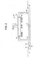
吸引器20は、第1のエンジンエア接続部44、第2のエンジンエア接続部46、および図2に示す空気圧作動式真空ポンプ50を含むことができる。吸引器20のエンジンエア接続部44は、スロットル28の上流およびコンプレッサー24の下流の位置で、エンジンエアシステム10に対して流体的に接続されてもよい。吸引器20のエンジンエア接続部46は、吸気マニホールド42の上流およびスロットル28の下流の位置で、エンジンエアシステム10に対して流体的に接続されてもよい。空気圧作動式真空ポンプ50は、真空キャニスター30に真空を供給するために使用されてもよい。具体的には、空気圧作動式真空ポンプ50によって供給される真空の大きさは、エンジンエアシステム10の特定の動作条件に基づいて調整されてもよく、以下でより詳細に説明される。吸引器20は、真空キャニスター30に真空を供給するように示されているが、当業者であれば、代替実施形態では、吸引器20が真空消費デバイス32に対して直接真空を供給することができることは明らかであろう。
The
真空消費デバイス32は、ブレーキブースターなどの真空を必要とするデバイスであってもよい。一実施形態では、真空消費デバイス32はまた、例えば、ターボチャージャーウェイストゲートアクチュエータ、加熱および換気アクチュエータ、駆動系アクチュエータ(例えば四輪駆動アクチュエータ)、燃料蒸気パージシステム、エンジンクランクケース換気、燃料システム漏れ試験システムといった、さらなる真空消費装置を同様に含むことができる。
The
図2は、図1に示される吸引器20の一実施形態の概略図であり、空気圧作動式真空ポンプ50を示している。空気圧作動式真空ポンプ50は、吸気マニホールド42における圧力に応じてアスピレーターまたはエジェクターのいずれかとして機能することができる。具体的には、アスピレーターは、その原動圧力が大気圧で、そしてその排出圧力が大気圧未満で固定された吸引器である。イジェクターは、その原動圧力が大気圧を上回る圧力で、そしてその排出圧力が大気圧で固定された吸引器である。
FIG. 2 is a schematic diagram of one embodiment of the
図1および図2を参照すると、本明細書で使用されるように、空気圧作動式真空ポンプ50は、三つ以上の接続部を有する収束・開拡ノズルアセンブリであってもよい。空気圧作動式真空ポンプ50は、エンジンエア接続部44に対して流体的に接続された原動ポート70と、エンジンエア接続部46に対して流体的に接続された排出ポート74と、真空キャニスター30に対してあるいは真空を必要とする一つ以上のデバイス32に対して流体的に接続された一つ以上の吸引ポート72とを含むことができる。複数の吸引ポート72が、図3の第1実施形態に、そして図8の第2実施形態ならびに図9の第3実施形態に示すように存在する場合、吸引ポート72’は、真空を必要とする同一のデバイス32または同一の真空キャニスター30に対して集合的に接続されてもよく、あるいは、真空を必要とする一つの可能なデバイスとして真空キャニスター30を含む、真空を必要とする異なるデバイス32aおよび32bに対して別個に接続されてもよい。
Referring to FIGS. 1 and 2, as used herein, the pneumatically actuated
具体的には、アスピレーター50の原動ポート70はコンプレッサー24の下流のエンジンエアシステム10に対して流体的に接続されてもよく、アスピレーター50の排出ポート74は吸気マニホールド42の上流のエンジンエアシステム10に対して流体的に接続されてもよい。当業者であれば、吸引器20はコンプレッサー24の下流のエンジンエアシステム10に接続されているので、これは、通常、コンプレッサー24と空気圧作動式真空ポンプ50の原動ポート70との間のチェックバルブの必要性を排除することを容易に理解するであろう。これは、スロットル28の上流にあるエンジンエア接続部44の圧力は、スロットル28の下流にあるエンジンエア接続部46の圧力よりも常に高くなければならないからである。
Specifically, the
図3は空気圧作動式真空ポンプ50の斜視図であり、図4は図3に示す空気圧作動式真空ポンプ50の分解図であり、そして図5は図4に示す分解された空気圧作動式真空ポンプ50の断面図である。図3ないし図5を参照すると、空気圧作動式真空ポンプ50の本体78は、軸線A‐Aに沿って延びる通路80(図5に示す)を画定することができる。図3ないし図5に示す実施形態では、空気圧作動式真空ポンプ50の本体78は、内燃エンジン12(図1)のサブシステムに対して接続可能な四つのポートを含む。具体的には、空気圧作動式真空ポンプ50は、原動ポート70、排出ポート74および二つの吸引ポート72を含むことができる。図示された非限定的な実施形態では、空気圧作動式真空ポンプ50は二つの吸引ポート72を含み、吸引ポート72の一つは空気圧作動式真空ポンプ50の上端部分84に沿って配置され、残りの吸引ポート72は空気圧作動式真空ポンプ50の下端部分86に沿って配置される。しかしながら、別な実施形態では、空気圧作動式真空ポンプ50の上端部分84または下端部分86のいずれかに沿って配置された、ただ一つの吸引ポート72のみが同様に使用されてもよいことは明白である。あるいは、別の実施形態では、図8に示すように、二つの吸引ポート72’は、以下でより詳細に説明されるように、いずれも空気圧作動式真空ポンプ50’の上端部分84’に沿って配置されてもよい。
3 is a perspective view of the pneumatically actuated
図5を参照すると、空気圧作動式真空ポンプ50の通路80は、この通路80の原動セクション90内に、(原動コーンとも呼ばれる)第1のテーパー部分92を含むことができる。通路80はまた、この通路80の排出セクション95内に、(排出コーンとも呼ばれる)第2のテーパー部分93を含むことができる。通路80の第1のテーパー部分92は、入口端部94および出口端部96を含むことができる。同様に、通路80の第2のテーパー部分93はまた、入口端部98および出口端部100を含むことができる。
Referring to FIG. 5, the
図5から分かるように、空気圧作動式真空ポンプ50の第1のテーパー部分92は、ベンチュリー間隙102Aによって、第2のテーパー部分93に対して流体的に結合することができる。ベンチュリー間隙102Aは、吸引ポート72を、空気圧作動式真空ポンプ50の原動セクション90および排出セクション95と流体連通状態とする流体接続部であってもよい。図6から最もよく分かるように、ベンチュリー間隙102Aは、第1のテーパー部分92の出口端部96と第2のテーパー部分93の入口端部98との間で測定された直線距離L1であってもよい。図示するような排出セクション95の入口端部98の認識に基づいて、第2、第3および第4のベンチュリー間隙102B,102Cおよび102Dは、全て、排出セクション95の一部と、特に原動セクション90から離れるように開拡する第2のテーパー部分93の一部と見なされる。空気圧作動式真空ポンプ50の第1のテーパー部分92の出口端部96は、ベンチュリー間隙102Aの入口を体現する。同様に、空気圧作動式真空ポンプ50の第2のテーパー部分93の入口端部98は、ベンチュリー間隙102Aの出口を体現する。
As can be seen in FIG. 5, the first
図5に戻ると、空気圧作動式真空ポンプ50の通路80の入口端部94,98および出口端部96,100は、これに限定されないが、円形、楕円形またはその他の多角形等の任意のタイプの輪郭を含むことができる。さらに、通路80の入口端部94,98および出口端部96,100から延びる、徐々に連続的に先細になる内径は、双曲面または円錐を画定することができる。第1のテーパー部分92の出口端部96および第2のテーパー部分93の入口端部98のいくつかの例示的な構成が、2014年6月3日に出願された係属中の米国特許出願第14/294,727号の図4ないし図6に示されており、その全体が参照により本明細書中に組み込まれる。
Returning to FIG. 5, the
再び図3ないし図5を参照すると、空気圧作動式真空ポンプ50の本体78はハウジング110を画定することができる。ハウジング110は、空気圧作動式真空ポンプ50の第2のテーパー部分93の一部を取り囲むかあるいはそれを形成してもよく、特にそれは間隙102A,102B,102C,102Dを有する。図示された実施形態では、ハウジング110は概して長方形の輪郭を含むことができるが、ハウジング110、特にその外観は長方形の輪郭に限定されない。
Referring again to FIGS. 3-5, the
図4ないし図6および図8に示すように、複数の付加的なベンチュリー間隙102B,102C,102Dが、ハウジング110内で、ベンチュリー間隙102Aの下流に配置される。図に示す実施形態では、空気圧作動式真空ポンプ50は合計四つのベンチュリー間隙を含む。これらの図は、空気圧作動式真空ポンプ50の単なる例示的な実施形態であり、任意の数のベンチュリー間隙が可能であることは明らかである。図8におけるような二重吸引ポートの実施形態に関して、少なくともベンチュリー間隙102Aが第1の吸引ポート72’aと流体連通することができ、かつ、少なくとも別なベンチュリー間隙102Bが第2の吸引ポート72’bと流体連通することができるように、少なくとも二つのベンチュリー間隙102Aおよび102Cが必要である。各吸引ポートに関して、複数のベンチュリー間隙は、各それぞれの吸引ポートとの整列および流体連通のために配置され、三つ、四つまたはそれ以上の総ベンチュリー間隙を再び提供してもよい。図8に示すように、ベンチュリー間隙102Aおよび102Bは第1の吸引ポート72’aと流体連通し、かつ、ベンチュリー間隙102Cおよび102Dは第2の吸引ポート72’bと流体連通する。三つまたは四つの吸引ポート(図示せず)と、図8に示すようなハウジング110の上面130の潜在的に二つの吸引ポート72’a,72’bと、ハウジング110の底面132の一つまたは二つの追加の吸引ポートとを有する実施形態では、最低限の三つまたは四つのベンチュリー間隙が存在するであろう。
As shown in FIGS. 4-6 and 8, a plurality of
各ベンチュリー間隙102A,102B,102C,102Dは、ハウジング110内に位置する空隙であってもよい。具体的には、ベンチュリー間隙102A,102B,102C,102Dはそれぞれ、ハウジング110の内部断面に類似していてもよい。例えば、図5から分かるように、ベンチュリー間隙102Aは、ハウジング110の内部断面に実質的に対応する略長方形の輪郭を含むことができる。空気圧作動式真空ポンプ50の第1のテーパー部分92を通る原動空気の流れは速度が増大してもよいが、低い静圧を生じる。この低い静圧は、空気を吸引ポート72,72’aからベンチュリー間隙102A内へとに引き込む。ベンチュリー間隙102Aの下流に位置する残りの間隙102B,102C,102Dは、一つ以上の吸引ポートからさらに空気を引き込むために使用されてもよい。図3ないし図5において、ベンチュリー間隙102B,102Cおよび102Dは同時に二つの吸引ポート72から空気を吸い込む。図8において、ベンチュリー間隙102Bは第1の吸引ポート72’aからさらに空気を引き込むために使用され、ベンチュリー間隙102Cおよび102Dは第2の吸引ポート72’bから空気を引き込む。同様に、図9の実施形態、吸引器50”では、第1の障害物202が第2の吸引ポート72’dからの空気の引き込みを防止するのでベンチュリー間隙102Aおよび102Bは第1の吸引ポート72’cからのみ空気を引き込み、かつ、第2の障害物204が第1の吸引ポート72’cからの空気の引き込みを防止するのでベンチュリー間隙102Cおよび102Dは第2の吸引ポート72’dからのみ空気を引き込む。
Each
図4および図5を参照すると、ハウジング110は上面130および底面132を含むことができる。上側チェックバルブ要素134および上側吸引部品136は上面130に対向して配置されてもよく、そして下側チェックバルブ要素140および下側吸引部品142は、空気圧作動式真空ポンプ50が組み立てられたとき(図3に示されている)、底面132に対向して配置されてもよい。上側チェックバルブ要素134および下側チェックバルブ要素140の両方が示されているが、別の実施形態では、ハウジング110は上側チェックバルブ要素134または下側チェックバルブ要素140のいずれかのみを含むことができることを理解されたい。特に、上側チェックバルブ要素134は、上側吸引部品136とハウジング110の上面130との間に配置されてもよく、そして下側チェックバルブ要素140は下側吸引部品142とハウジング110の底面132との間に配置されてもよい。一実施形態では、上側吸引部品136および下側吸引部品142は、吸引ポート72を真空キャニスター30(図1)に接続するホース(図示せず)と係合するための返し150をそれぞれ含むことができる。図8および図9の実施形態に関して、図3ないし図5に関して特定され説明されたものと同一または類似の部品または部分には同じ参照数字が付されている。
With reference to FIGS. 4 and 5, the
上側チェックバルブ要素134および下側チェックバルブ要素140は、例えばエラストマーのような比較的可撓性のある材料で構成することができる。可撓性材料は、空気圧作動式真空ポンプ50の動作中に、上側チェックバルブ要素134および下側チェックバルブ要素140が曲がることをあるいは変形することを可能にする。
The upper
ここで図4に戻ると、上側チェックバルブ要素134は第1のセクション160を含んでいてもよく、下側チェックバルブ要素140は第1のセクション162を含んでいてもよい。上側チェックバルブ要素134および下側チェックバルブ要素140の第1のセクション160,162はそれぞれ、空気圧作動式真空ポンプ50の軸線A‐Aと実質的に平行である。複数の外向きに突出するフィンガーまたはタブ166A、166B,166C,166Dは、上側チェックバルブの第1のセクション160に対して、外向きにかつ概ねそれと交差する方向に延びることができる。同様に、複数の外側に突出するフィンガーまたはタブ170A,170B,170C,170Dは、下側チェックバルブ要素140の第1の部分162に対して概ね交差する方向に延びる。複数のタブのそれぞれは、第1のセクション160の一方の側から、または第1のセクションの両側から、典型的には互いに向かい合って整列した状態で延在してもよい。
Returning now to FIG. 4, the upper
上側チェックバルブ要素134のタブ166A,166B,166C,166Dのそれぞれは、ベンチュリー間隙102A,102B,102C,102Dの一つに対応してもよく、そしてそれに対して流体的に接続される。同様に、下側チェックバルブ要素140のタブ170A,170B,170C,170Dのそれぞれはまた、存在する場合には、ベンチュリー間隙102A,102B,102C,102Dの一つに対応してもよく、そしてそれに対して流体的に接続される。図4から分かるように、リセス174は、下側吸引キャップ142の上面176に沿って配置されてもよい。リセス174は、下側チェックバルブ要素140に概ね対応する輪郭を含むことができる。したがって、下側チェックバルブ要素140は下側吸引キャップ142のリセス174内に着座させられてもよい。類似のリセス(図面では認識できない)がまた、同様に、上側吸引キャップ146の下面180に沿って配置されてもよく、そしてそれは上側チェックバルブ要素134と概ね対応する輪郭を含むことは明らかである。
Each of the
特に図4を参照すると、空気圧作動式真空ポンプ50の上側吸引ポート72に置かれた圧力がベンチュリー間隙102A,102B,102D,102D内の圧力に等しいかそれよりも小さい場合、上側チェックバルブ要素134は上側吸引キャップ146内で面一に着座させられてもよく、タブ166A,166B,166C,166Dは曲げられない。同様に、空気圧作動式真空ポンプ50の下側吸引ポート72に置かれた圧力がベンチュリー間隙102A,102B,102C,102D内の圧力に等しいかそれよりも小さい場合、下側チェックバルブ要素140は下側吸引キャップ142内で面一に着座させられてもよく、タブ170A,170B,170C,170Dは曲げられない。チェックバルブ134,140が閉位置にあるとき、空気圧作動式真空ポンプ50の上側および下側吸引ポート72からの空気は、ベンチュリー間隙102A,102B,102C,102D内に吸引されないことがある。
With particular reference to FIG. 4, if the pressure placed on the
ベンチュリー間隙102A,102B,102C,102D内の圧力よりも空気圧作動式真空ポンプ50の上側吸引ポート72に置かれた圧力が高いとき、上側チェックバルブ要素134は開くことができる。具体的には、上側チェックバルブ134は、タブ166A,166B,166C,166Dが第1の部分160に沿って内向きにかつベンチュリー間隙102A,102B,102C,102Dに向かって曲がることができるように十分にフレキシブルであり、これによって上側吸引ポート72からの空気がベンチュリー間隙102A,102B,102C,102D内に吸引されることが可能となる。同様に、空気圧作動式真空ポンプ50の下側吸引ポート72に置かれた圧力がベンチュリー間隙102A,102B,102C,102D内の圧力よりも高い場合、下側チェックバルブ要素140は開くことができる。具体的には、下側チェックバルブ140は、タブ170A,170B,170C,170Dが第1の部分162に沿って内向きにかつベンチュリー間隙102A,102B,102C,102Dに向かって曲がることができるように十分にフレキシブルであり、これによって下側吸引ポート72からの空気がベンチュリーの間隙102A,102B,102C,102D内に吸引されることが可能となる。
The upper
当業者であれば、上側チェックバルブ要素134のタブ166A,166B,166C,166Dのそれぞれは互いに独立して曲がることができることを容易に理解するであろう。同様に、下側チェックバルブ要素140のタブ170A,170B,170C,170Dのそれぞれはまた、互いに独立して屈曲してもよい。したがって、空気圧作動式真空ポンプ50の動作中、ベンチュリー間隙102A,102B,102C,102Dの一部のみが、空気が真空キャニスター30(図1)から吸引されることを可能とするために、その対応するチェックバルブを開放状態としてもよく、一方、残りのベンチュリー間隙102A,102B,102C,102Dは、その対応するチェックバルブを閉鎖状態としてもよい。
One of ordinary skill in the art will readily appreciate that each of the
図6は、空気圧作動式真空ポンプ50のハウジング110内に置かれたベンチュリー間隙102A,102B,102C,102Dの拡大横断断面図である。上述したように、ベンチュリー間隙102Aは、(図5に見られる)第1のテーパー部分92の出口端部96と(図5に見られる)第2のテーパー部分93の入口端部98との間で測定された直線距離L1として規定されてもよい。残りのベンチュリー間隙102B,102C,102Dもまた、それぞれ直線距離L2,L3,L4を含む。これらの直線距離はそれぞれ、各間隙のそれぞれの入口壁および出口壁から測定される。特に、ベンチュリー間隙102Bは、入口面182と出口面184との間で測定され、ベンチュリー間隙102Cは、入口面186と出口面188との間で測定され、そしてベンチュリー間隙102Dは、入口面190と出口面192との間で測定される。入口面182,186,190および出口面184,188,192は全て空気圧作動式真空ポンプ50のハウジング110によって画定される。
FIG. 6 is an enlarged cross-sectional view of
図7は、排出ポート74から見た空気圧作動式真空ポンプ50の図である。図6および図7を参照すると、空気圧作動式真空ポンプ50の第2のテーパー部分93の開拡輪郭は、各ベンチュリー間隙102A,102B,102Cおよび102Dの入口および出口開口におけるオフセットまたは差を形成する。図5、図7、図8および図9から分かるように、ベンチュリー間隙102A,102B,102C,102Dの入口開口および出口開口はそれぞれ実質的に楕円形の輪郭を含む。しかしながら、上述したように、別の実施形態では、入口および出口開口は、その代わりに、別のタイプの輪郭を含むことができる。図7に示されるように、但し図5、図8および図9にも適用可能であるように、第1のテーパー部分92の出口端部(これはベンチュリー間隙102Aの入口を体現する)は開口O1を含み、そして第2のテーパー部分93の入口端部98(これはベンチュリー間隙102Aの出口を体現する)は開口O2を含む。出口の開口O2の輪郭は、ベンチュリー間隙102Aの入口の開口O1よりも大きくなるような寸法とされている。言い換えれば、ベンチュリー間隙102Aの入口開口と出口開口との間にはオフセットが存在する。第1のオフセット1は、ベンチュリー間隙102Aの入口開口と出口開口との間の差を表す。一つの非限定的な実施形態では、第1のオフセット1は約0.25ミリメートルであってもよい。
FIG. 7 is a view of the pneumatically actuated
図6および図7の両方を引き続き参照すると、開口O3はベンチュリー間隙102Bの入口面182に関連付けられ、開口O4は第2の間隙102Bの出口面184に関連付けられる。ベンチュリー間隙102Aと同様に、出口面184の開口O4は入口面182の開口O3よりも大きい。第2のオフセット2は、第2の間隙102Bの入口面182と出口面184との間の差を表す。同様に、開口O5はベンチュリー間隙102Cの入口面186に関連付けられ、開口O6はベンチュリー間隙102Cの出口188に関連付けられる。第3のオフセット3は、ベンチュリー間隙102Cの入口面186と出口面188との間の差を表す。最後に、開口O7はベンチュリー間隙102Dの入口面190に関連付けられ、開口O8はベンチュリー間隙102Dの出口192に関連付けられる。第4のオフセット4は、ベンチュリー間隙102Dの入口面190と出口面192との間の差を表す。
With continued reference to both FIGS. 6 and 7, the
概して図5および図6を参照すると、動作中に、空気圧作動式真空ポンプ50の本体78内に最小圧力領域が形成され得る。特に、最小圧力領域は、空気圧作動式真空ポンプ50のベンチュリー間隙102A,102B,102C,102Dの一つ以上に隣接してあるいはその中に置かれてもよい。最小圧力領域はまた、空気圧作動式真空ポンプ50内の最大速度領域を表す。当業者であれば、空気圧作動式真空ポンプ50がエジェクターとして作動している場合、空気圧作動式真空ポンプ50の原動圧力が増大するにつれて空気圧作動式真空ポンプ50内の最小圧力の位置が第2のテーパー部分73内で下流にシフトするかまたは移動し得ることを容易に理解するであろう。空気圧作動式真空ポンプ50内の最小圧力の位置がベンチュリー間隙102Aの下流にシフトするにつれて、ベンチュリー間隙102B,102C,102Dは真空キャニスター30から空気をさらに吸引するために利用できる。当業者であれば、空気圧作動式真空ポンプ50がアスピレーターとして作動している場合、排出ポート74の圧力が減少するにつれて最小圧力の位置もまた同様に下流にシフトするかまたは移動し得ることを容易に理解するであろう。
Referring generally to FIGS. 5 and 6, during operation, a minimum pressure region may be formed within the
引き続き図6を参照すると、空気圧作動式真空ポンプ50のハウジング110内に配置されたベンチュリー間隙102A,102B,102C,102Dのそれぞれの直線距離L1,L2,L3,L4は、空気圧作動式真空ポンプ50内の最小圧力の位置を適応させるために調節または調整されてもよい。具体的には、空気圧作動式真空ポンプ50のハウジング110内に位置するベンチュリー間隙102A,102B,102C,102Dの直線距離L1,L2,L3,L4の一つは、特定の動作条件のセットで、より高い吸引真空(すなわち、より低い吸引圧力)が望まれる場合、より狭くなるかまたは長さが小さくなるように設計されてもよい。
Continuing to refer to FIG. 6, the respective linear distances L1, L2, L3, L4 of the
ベンチュリー間隙102A,102B,102C,102Dの一つの長さを減少させることに加えて、オフセット距離(すなわち、第1のオフセット1、第2のオフセット2、第3のオフセット3または第4のオフセット4)を、特定の動作条件のセットにおいて、より高い吸引真空(すなわち、より低い吸引圧力)を生成するために同様に減少させることができる。換言すれば、ベンチュリー間隙の特定のものの長さが短くなると、特定の間隙のそれぞれの入口開口と出口開口との間の差もまた同様に減少すべきである。同様に、空気圧作動式真空ポンプ50のハウジング110内に配置されたベンチュリー間隙102A,102B,102C,102Dの直線距離L1,L2,L3,L4の一つは、特定の動作条件のセットにおいてより高い吸引流量が望ましい場合には、より幅広となるかあるいは長さが増大するように設計されてもよい。ベンチュリー間隙102A,102B,102C,102Dの一つの長さを増大させることに加えて、ベンチュリー間隙の一つと関連付けられたオフセット距離(すなわち、第1のオフセット1、第2のオフセット2、第3のオフセット3または第4のオフセット4)は、特定の動作条件のセットでより高い吸引流速を生成するために同様に増大させられるべきである。換言すれば、ベンチュリー間隙の特定のものの長さが大きくなると、特定の間隙のそれぞれの入口開口と出口開口との間の差もまた同様に増大すべきである。
In addition to reducing the length of one of the
特定の動作条件のセットは、原動ポート70および空気圧作動式真空ポンプ50の排出ポート74の両方の圧力によって規定されてもよい。例えば、動作条件のあるセットの間、原動ポート70は、排出ポート74が大気圧の約80%である場合には、大気圧である。この動作条件のセットの間、空気圧作動式真空ポンプ50はアスピレーターとして動作している。この例では、空気圧作動式真空ポンプ50内の最小圧力の位置は、ベンチュリー間隙102Aにあると仮定するかまたは特定することができる。エンジン12(図1に示す)が、これらの例示的な条件をかなりの時間にわたって生成するように動作する場合、設計者または技術者は、それに応じてベンチュリー間隙102Aの直線距離L1を調整するために、それを概ね有利に決定し得る(すなわち、ベンチュリー間隙102Aの直線距離L1は必要に応じて広げられたり狭められたりする必要がある)。直線距離L1を調整することに加えて、第2のオフセット2もまた同様に相応に調整することができることを理解されたい。例えば、ベンチュリー間隙102Aの線形距離L1が増大するとき、第2のオフセット2は同様に増大してもよい。同様に、ベンチュリー間隙102Aの線形距離L1が減少するとき、第2のオフセット2は同様に減少してもよい。
The particular set of operating conditions may be defined by the pressure of both the
別の例示的な例では、原動ポート70の圧力が大気圧よりも高い場合(例えば、約168キロパスカル)、そして排出ポート74もまた大気圧よりも高いが原動ポート70よりも低い場合(例えば、約135キロパスカル)、空気圧作動式真空ポンプ50はエジェクターとして動作している。この例では、空気圧作動式真空ポンプ50内の最小圧力の位置はベンチュリー間隙102Cにあると仮定されるかあるいは特定される。エンジン12(図1に示す)が、これらの例示的な条件をかなりの時間にわたって生成するように動作する場合、設計者または技術者は、それに応じてベンチュリー間隙102Cの直線距離L3を調整するために、それを概ね有利に特定し得る(すなわち、ベンチュリー間隙102Cは広げられたり狭められたりするべきである)。ベンチュリー間隙102Cの直線距離L3を調整することに加えて、第3のオフセット3もまた同様に調整することができることを理解されたい。例えば、ベンチュリー間隙102Cの線形距離L3が増大する場合、第3のオフセット3は同様に増大してもよい。同様に、ベンチュリー間隙102Cの直線距離L3が減少する場合、第3のオフセット3は同様に減少してもよい。
In another illustrative example, if the pressure at the
ここで、図8および図9を参照すると、二つの代替実施形態が提供されるが、ここでは、第1および第2のベンチュリー間隙102Aおよび102Bはそれぞれ第1の吸引ポート72’a,72’cと流体連通状態であり、かつ、第2および第3のベンチュリー間隙102Cおよび102Dはそれぞれ第2の吸引ポート72’b,72’dと流体連通状態である。流体連通は、チェックバルブ要素134および/または140(存在する場合)の存在によって制御される。第1の吸引ポート72’a,72’cは、真空を必要とする第1のデバイス32aに接続され、第2の吸引ポート72’b,72’dは、真空を必要とする第2のデバイス32bに接続される。
Referring now to FIGS. 8 and 9, two alternative embodiments are provided where the first and
この第1の専用吸引ポート実施形態では、真空を必要とする第1のデバイス32aはブレーキブーストキャニスターであり、真空を必要とする第2のデバイス32bは燃料蒸気パージキャニスターである。この第1実施形態に関して、図8および図9の両方に示すように、第1および第2のベンチュリー間隙102Aおよび102Bは、原動出口により近く配置される。ベンチュリー間隙のこの位置は、より高い高真空吸引にとって有利であるが、これは、排出セクション95の出口端部100により近いこれらのベンチュリー間隙と比較して、ブレーキブーストシステムにとって望ましい。さらに、上述したように、第1および第2のベンチュリー間隙は、直線距離L1を減少させることによって、かつ/または第1のオフセット1および/または第2のオフセット2を減少させることによって、より高い真空吸引のために調整することができる。この第1実施形態では、第3および第4のベンチュリー間隙102Cおよび102Dは、排出セクション95の出口端部100のより近くに接続されている。ベンチュリー間隙のこの位置は、通常はより長い時間にわたる、より高い吸引流速のために有利であるが、これは、第1および第2のベンチュリー間隙102Aと比較して、燃料蒸気パージキャニスターのために望ましい。さらに、上述したように、第3および第4のベンチュリー間隙102Cおよび102Dは、直線距離L3および/またはL4を増大させることによって、かつ/または第3のオフセット3および/または第4のオフセット4を増大させることによって、より高い真空吸引のために調整することができる。
In this first dedicated suction port embodiment, the
別の専用吸引ポート実施形態では、真空を必要とする第1のデバイス32aはターボチャージャーバイパス空気圧アクチュエータであり、真空を必要とする第2のデバイス32bは燃料蒸気パージキャニスターである。ここで、図8および図9の両方に示すように、第1および第2のベンチュリー間隙102Aおよび102Bは、真空を必要とする第1のデバイスに接続され、原動出口により近く配置される。ベンチュリー間隙のこの位置は、より高い真空吸引のために有利であり、これはターボチャージャーバイパス空気圧アクチュエータにとって望ましい。さらに、上述したように、第1および第2のベンチュリー間隙102Aおよび102Bは、直線距離L1を減少させることによって、かつ/または第1のオフセット1および/または第2のオフセット2を減少させることによって、より高い真空吸引のために調整することができる。さらに、ターボチャージャーバイパス空気圧アクチュエータを作動させるために付加的な真空が必要である場合、第3のベンチュリー間隙102Cはまた、第1の吸引ポート72’a,72’cのみと流体連通することができる。したがって、第3および第4のベンチュリー間隙102Cおよび102D、または第4のベンチュリー間隙102Dのみ、または第4のベンチュリー間隙102Dおよび一つ以上の付加的なベンチュリー間隙(図示せず)は、真空を必要とする第2のデバイス32bと流体連通することができる。排出セクション95の出口端部100により近いベンチュリー間隙のこの位置は、通常はより長い時間にわたる、より高い吸引流速のために有利であるが、これは、燃料蒸気パージキャニスターのために望ましい。さらに、上述したように、これらベンチュリー間隙は、そのそれぞれの直線距離を増大させ、かつ/またはそのそれぞれのオフセット3を増大させることによって、より高い吸引流速のために調整することができる。
In another dedicated suction port embodiment, the first
真空を必要とする第1および第2のデバイス32a,32bに関して、さまざまなデバイスの組み合わせが可能であり、さらに、上述したように、真空を必要とする第3および/または第4のデバイスは、さらなる吸引ポートによって同様に同じ吸引器に接続されてもよいことを理解されたい。真空を必要とするデバイスの数およびデバイスのタイプに依存して、それぞれのデバイスに接続されたベンチュリー間隙102A,102B,102C,102Dは、高いかまたは低い吸引真空および高いかまたは低い吸引流速に関するデバイスの必要性に応じて選択されるべきであり、それらはこの必要性へと調節または調整することができる。例えば、一実施形態では、ベンチュリー間隙102A,102B,102C,102Dは、動作条件の第1のセットで、より高い吸引流速を提供するために長さが増大させられてもよく、残りのベンチュリー間隙102A,102B,102C, 102Dは、別の動作条件のセットで、より高い吸引真空を提供するために、長さが減少させられてもよい。
Various device combinations are possible for the first and
再び図9を参照すると、ベンチュリー間隙102A〜102D間の流体連通は、チェックバルブ要素134,140の存在によって制御される。ここで、第1および第2のベンチュリー間隙102Aおよび102Bのみが第1の吸引ポート72’cと流体連通するので、下流のベンチュリー間隙と第1の吸引ポート72’cとの間の流体連通を妨げる(防止する)障害物204が存在する。同様に、第3および第4のベンチュリー間隙102Cおよび102Dのみが第2の吸引ポート72’dと流体連通するので、上流のベンチュリー間隙と第2の吸引ポート72’dとの間の流体連通を妨げる(防止する)障害物202が存在する。
Referring again to FIG. 9, fluid communication between the
代替実施形態では、図10に示すように、選択されたベンチュリー間隙と協調する障害物202または204を有するのではなく、硬質なその選択されたタブ、右側セクション212に含まれるもの、および弾性的にフレキシブルなその他の選択されたタブ、左側セクション210に含まれるものを含むチェックバルブ要素208が、閉位置と開位置との間を移動するように設けられる。チェックバルブ要素208は、半分の剛性タブおよび半分の可撓性タブを有するように図示されているが、剛性および可撓性タブは、選択されたベンチュリー間隙およびそのそれぞれの吸引ポートと協調するために必要に応じて分散されてもよい。
In an alternative embodiment, as shown in FIG. 10, rather than having an
図8に示すように、フレッチインサート220が、本明細書で開示する実施形態のいずれかに含まれてもよい。フレッチインサート220は、参照によりその全体が本明細書中に組み込まれる、2014年8月27日に出願された同時係属・同時所有の米国仮特許出願第62/042,569号において説明される。
As shown in FIG. 8, a fret
ここで図11を参照すると、真空を提供するための例示的なターボ過給エンジンエアシステム300が開示されている。エンジンエアシステム300は、内燃エンジン312、エアクリーナー314、第1の吸引器330、コンプレッサー324、タービン(図示せず)、スロットル328、燃料蒸気キャニスター331および第2の吸引器360を含むことができる。以下でより詳細に説明するように、第1および第2の吸引器330,360は、ブレーキブーストキャニスター(図11には図示せず)、燃料蒸気キャニスター331およびクランクケース換気システム352といった、複数の真空消費デバイスに真空を提供できる。
Referring now to FIG. 11, an exemplary turbocharged
図1に示す実施形態と同様、内燃エンジン312は、例えば、SIエンジン、CIエンジンまたはハイブリッド車両における電気モーター/バッテリシステムの一部であってもよい。コンプレッサー324およびタービンは、内燃エンジン312の出力および全体効率を改善するためのターボチャージャーの一部であってもよい。タービンは、コンプレッサー324の(図11には示されていない)コンプレッサーホイールを回転させるための共通のシャフトを介して、排気エネルギーを利用し、それを機械的仕事に変換する(図11には示していない)タービンホイールを含んでいてもよい。コンプレッサーホイールは、上昇した作動圧力で空気を取り込み、圧縮し、そして内燃エンジン312の吸気マニホールド342にそれを供給する。
Similar to the embodiment shown in FIG. 1, the
第1の吸引器330には、スロットル328の上流でかつチャージエアクーラー(図示せず)の下流にあるコンプレッサー324から空気が供給される。具体的には、大気圧のクリーンエアはエアクリーナー314を出て行き、第1の吸引器330を通過する前にコンプレッサー324によって圧縮されてもよい。スロットル328は、エアクリーナー314およびコンプレッサー324の下流で、かつ、内燃エンジン312の吸気マニホールド342の上流に配置される。
Air is supplied to the
第1の吸引器330は、第1のエンジンエア接続部344、第2のエンジンエア接続部346および空気圧作動式真空ポンプ350を含むことができる。第1のエンジンエア接続部344は第1の吸引器330の原動入口332と流体連通状態であってもよく、そして第2のエンジンエア接続部346は第1の吸引器330の排出出口334と流体連通状態であってもよい。図11から分かるように、第1のエンジンエア接続部344は、スロットル328の上流でかつコンプレッサー324の下流の位置でエンジンエアシステム300に対して流体的に接続され、かつ、第2のエンジンエア接続部346は、吸気マニホールド342の上流でかつスロットル328の下流の位置でエンジンエアシステム300に対して流体的に接続される。
The
空気圧作動式真空ポンプ350は、複数の真空消費デバイスに真空を供給することができる。特に、空気圧作動式真空ポンプ350は、ブレーキブーストキャニスター(図示せず)、燃料蒸気キャニスター331およびクランクケース換気システム352に真空を供給する。以下で詳しく説明するように、空気圧作動式真空ポンプ350は、複数の吸引ポートA1,B1,C1,D1を介して、ブレーキブーストキャニスター、燃料蒸気キャニスター331およびクランクケース換気システム352に対して流体的に接続される。当業者であれば、ブレーキブーストキャニスター、燃料蒸気キャニスター331およびクランクケース換気システム352が図11に示されているが、第1および第2の吸引器330,360は車両内の他の真空消費デバイスに同様に真空を提供するために追加の吸引ポートを備えてもよいことは明らかであろう。あるいは、第1および第2の吸引器330,360は、代わりに、車両内の異なる真空消費デバイスに真空を提供してもよい。
The pneumatically actuated
空気圧作動式真空ポンプ350は、図8および図9に示された吸引器と実質的に同じ構造を有していてもよく、これについて以下で詳しく説明する。特に、空気圧作動式真空ポンプ350の吸引ポートA1は、図8および図9に示す吸引器のベンチュリー間隙102Aに対応してもよく、空気圧作動式真空ポンプ350の吸引ポートB1は、図8および図9に示す吸引器のベンチュリー間隙102Bに対応してもよく、吸引ポートC1は、図8および図9に示す吸引器のベンチュリー間隙102Cに対応していてもよく、最後に、吸引ポートD1は、図8および図9に示す吸引器のベンチュリー間隙102Dに対応してもよい。空気圧作動式真空ポンプ350の吸引ポートA1および吸引ポートB1は共にブレーキブースターシステム(図示せず)に対して流体的に接続される。空気圧作動式真空ポンプ350の吸引ポートC1は、燃料蒸気キャニスター331に対して流体的に接続される。空気圧作動式真空ポンプ350の吸引ポートD1は、クランクケース換気システム352に対して流体的に接続される。
The pneumatically actuated
第1の吸引器330は、エンジン312の運転中、さまざまな真空要求システム(すなわち、ブレーキブースターシステム、燃料蒸気キャニスター331、およびクランクケース換気システム352)に連続的に吸引作用を提供することができる。特に、第1の吸引器330は、エンジンエアシステム300の特定の動作条件に基づいて、エジェクターまたはアスピレーターのいずれかとして動作することができる。例えば、第1の吸引器330の原動入口332が大気圧である場合、そして第1の吸引器330の排出出口334が大気圧よりも低い場合、第1の吸引器330はアスピレーターとして動作することができる。同様に、第1の吸引器330の原動入口332が大気圧を超える場合、そして第1の吸引器330の排出出口334の圧力が少なくとも大気圧であるが原動入口332の圧力未満である場合、第1の吸引器330はエジェクターとして動作することができる。当業者であれば、第1の吸引器330がエジェクターとして動作するかアスピレーターとして動作するかに関係なく、エンジン312が作動しているときに、第1の吸引器330の原動入口332の圧力は、第1の吸引器330の排出出口334の圧力よりも常に大きいことを容易に理解するであろう。
The
引き続き図11を参照すると、第2の吸引器360は、導管ライン368によって表されるように燃料蒸気キャニスター331と、そしてライン369によって表されるようにクランクケース換気システムと流体的に接続された原動入口362を含む。第2のエジェクター360は、導管ライン370によって表されるように、吸気マニホールド342の上流およびスロットル328の出口329の下流の位置において、エンジンエアシステム300に対して流体的に接続された排出出口364を含む。チェックバルブ366が、排出出口364と第2の吸引器360との間の導管ライン370に、そしてスロットル328と吸気マニホールド342との間の接合部に含まれてもよい。
With continued reference to FIG. 11, the
第2の吸引器360は、空気圧作動式真空ポンプ380であってもよい。第1の吸引器330と同様、空気圧作動式真空ポンプ380は、図8およ図9に示す吸引器と同じ構造を含むことができるが、これについては以下で詳しく説明する。空気圧作動式真空ポンプ380は、ブレーキブーストキャニスター(図示せず)、燃料蒸気キャニスター331およびクランクケース換気システム352に真空を供給する。以下で詳しく説明するように、空気圧作動式真空ポンプ380は、複数の吸引ポートA2,B2,C2およびD2を介して、ブレーキブーストキャニスター、燃料蒸気キャニスター331およびクランクケース換気システム352に対して流体的に接続される。
The
図11に示すように、空気圧作動式真空ポンプ380の吸引ポートA2および吸引ポートB2は、いずれも、ブレーキブースターシステム(図示せず)に対して流体的に接続される。空気圧作動式真空ポンプ380の吸引ポートC2は、燃料蒸気キャニスター331に対して流体的に接続されている。空気圧作動式真空ポンプ380の吸引ポートD2は、クランクケース換気システム352に対して流体的に接続される。第1の吸引器330と同様、第2の吸引器360は、真空を必要とする三つのシステム(すなわち、ブレーキブーストキャニスター、燃料蒸気キャニスター331およびクランクケース換気システム352)に対して接続される。図11は本質的に単なる例示であり、第2の吸引器360は説明した三つの真空消費デバイスに限定される必要はないことを理解されたい。
As shown in FIG. 11, both suction port A2 and suction port B2 of pneumatically actuated
第2の吸引器360は、図8および図9に示す吸引器と同様の構造を有することができ、これについては以下で詳しく説明する。第1の吸引器330とは異なり、第2の吸引器360は、エンジン312が作動しているとき、エジェクターまたはアスピレーターのいずれかとして真空を連続的に提供しなくてもよい。代わりに、第2の吸引器360は、第2の吸引器360の原動入口362の圧力が大気圧でありかつ排出出口364の圧力が原動入口362の圧力よりも低い場合には、さまざま真空を必要とするシステムに対して真空を生成するように動作し得る。言い換えると、第2の吸引器360は、エンジン312の動作中、アスピレーターとしてのみ動作し、エジェクターとしては動作しない。
The
エンジンエアシステム300は、エンジン312の動作中に、第1の吸引器330のみがさまざまな真空を必要とするシステムに真空を提供するように動作することができる。換言すれば、第1の吸引器330はアスピレーターまたはエジェクターとして動作する。しかしながら、第2の吸引器は、真空を生成するようには動作していなくてもよい(すなわち、第2の吸引器360の原動入口362の圧力は大気圧より大きい)。代替的に、エンジンエアシステム300は、エンジン312の動作中に、第1の吸引器330および第2の吸引器360の両方がさまざまな真空を必要とするシステムに吸引作用を提供するように動作してもよい。
The
図11に示すように、第1の吸引器330および第2の吸引器360は、同じ真空を必要とするデバイスに接続された複数の吸引ポートを有する。具体的には、第1の吸引器330の原動入口332に最も近接して配置された第1の吸引ポートA1は、ブレーキブースターシステムに対して流体的に接続される。第1の吸引器330の吸引ポートA1に直に隣接して配置される吸引ポートB1は、ブレーキブースターシステムに対して同様に流体的に接続される。上述したように、吸引ポートA1,B1が第1の吸引器330の原動入口332に近接することにより、ブレーキブーストシステムによって要求されるよりも高い真空吸引が容易になる。同様に、第2の吸引器360の原動入口362に最も近接して配置された第1の吸引ポートA2もまた、ブレーキブースターシステムに対して流体的に接続される。第2の吸引器360の吸引ポートA2に直に隣接して配置される吸引ポートB2は、ブレーキブースターシステムに対して同様に流体的に接続される。吸引ポートA2,B2が第2の吸引器360の原動入口362に近接することにより、同様に、より高い真空吸引が容易になる。
As shown in FIG. 11, the
引き続き図11を参照すると、第1の吸引器330の吸引ポートB1に直に隣接する第3の吸引ポートC1は、燃料蒸気パージシステムに対して流体的に接続されている。第1の吸引器330の排出出口334に直に隣接する第4の吸引ポートD1は、クランクケース換気システム352に対して流体的に接続される。上述したように、第1の吸引器330の排出出口334への吸引ポートC1,D1の接近は、より高い吸引流速を促進する。同様に、第2の吸引器360の吸引ポートB2に直に隣接する第3の吸引ポートC2もまた、燃料蒸気パージシステムに対して流体的に接続される。第2の吸引器360の排出出口364に直に隣接する第4の吸引ポートD2は、クランクケース換気システム352に対して流体的に接続される。第2の吸引器360の排出出口364への吸引ポートC2,D2の接近は、同様に、より高い吸引流速を促進する。
With continued reference to FIG. 11, the third suction port C1 immediately adjacent to the suction port B1 of the
図11から分かるように、第2の吸引器360の原動入口362は、クランクケース換気システム352および燃料蒸気キャニスター331の両方に対して流体的に接続される。したがって、クランクケース換気システム352および燃料蒸気キャニスター331によって消費されるエンジンエアは、そのまさに同じシステムそれ自体によって使用される真空を生成するために使用できる。換言すれば、第2の吸引器360は、クランクケース換気システム352および燃料蒸気キャニスター331によって消費されるエンジンエアを利用して真空を生成することができる。第2の吸引器360によって生成された真空は、最終的に、クランクケース換気システム352および燃料蒸気キャニスター331によって消費される。さらに、真空はまた、ブレーキブーストキャニスターのような、その他の真空消費デバイスによって、同様に使用され得る。
As can be seen in FIG. 11, the
ここで図12を参照すると、車両真空システムに真空を供給するためのターボ過給エンジンエアシステム300’の別の例示的な実施形態が開示されている。エンジンエアシステム300’は、図11のシステム300の全ての構成要素を含み、同じ参照数字は同じ構成要素を示し、その説明は繰り返さない。エンジンエアシステム300’は、上述したように第2の吸引器360を含む。しかしながら、図11に示す実施形態と異なり、第2の吸引器360の原動入口362は、クランクケース換気システム352のみと流体連通状態であり、燃料蒸気キャニスター331と流体連通していない。さらに、エンジンエアシステム300’はさらに、第3の吸引器360’および第2のチェックバルブ366’を含む。第3の吸引器360’は、第1および第2の吸引器350,360がクランクケース換気システム352および燃料蒸気キャニスター331の両方に十分な真空を提供できない場合に含まれてもよい。
Referring now to FIG. 12, another exemplary embodiment of a turbocharged engine air system 300 'for providing a vacuum to a vehicle vacuum system is disclosed. Engine air system 300 'includes all components of
引き続き図12を参照すると、第3の吸引器360’は、原動ぽ入口362’と排出出口364’とを含む。第3の吸引器360’の原動入口362’は、燃料蒸気キャニスター331と流体連通している。第3の吸引器360’の排出出口364’は、導管ライン370と流体連通している。第2のチェックバルブ366’は、排出出口364’と導管ライン370との間に配置される。
Continuing to refer to FIG. 12, the third aspirator 360 'includes a drive inlet 362' and a discharge outlet 364 '. The drive inlet 362 'of the third suction device 360' is in fluid communication with the
第2の吸引器360と同様、第3の吸引器360’はまたアスピレーターとしてのみ動作することもできる。言い換えれば、第3の吸引器360’は、エンジン312が作動しているときに連続的な真空を提供しない。その代わりに、第3の吸引器360’は、原動入口362’の圧力が第1の圧力である場合に、さまざまな真空を必要とするシステム(すなわち、ブレーキブースターシステム、燃料蒸気キャニスター331およびクランクケース換気システム352)に真空を生成するよう作動し得る。
Like the
第3の吸引器360’は、空気圧作動式真空ポンプ380’を含む本体を含む。第1および第2の吸引器330,360と同様、空気圧作動式真空ポンプ380’は、図8および図9に示す吸引器と同じ構造を有することができるが、これについては以下で詳しく説明する。空気圧作動式真空ポンプ380は、ブレーキブーストキャニスター(図示せず)、燃料蒸気キャニスター331およびクランクケース換気システム352に真空を供給する。具体的には、空気圧作動式真空ポンプ380は、ブレーキブーストキャニスター、燃料蒸気キャニスター331およびクランクケース換気システム352に対して複数の吸引ポートA3,B3,C3,D3を介して流体的に接続される。
The third aspirator 360 'includes a body that includes a pneumatically actuated vacuum pump 380'. Like the first and
図11から分かるように、空気圧作動式真空ポンプ380’の吸引ポートA3および吸引ポートB3は、両方とも、ブレーキブースターシステム(図示せず)に対して流体的に接続されている。空気圧作動式真空ポンプ380’の吸引ポートC3は、燃料蒸気キャニスター331に対して流体的に接続されている。空気圧作動式真空ポンプ380’の吸引ポートD3は、クランクケース換気システム352に対して流体的に接続されている。第1および第2の吸引器330,360と同様、第3の吸引器360’もまた、真空を必要とする三つのシステム(すなわちブレーキブーストキャニスター、燃料蒸気キャニスター331およびクランクケース換気システム352)に接続されている。さらに、図12は本質的に単に例示的なものであり、第3の吸引器360’は、説明したような三つの真空消費デバイスに限定される必要はないことを理解されたい。
As can be seen in FIG. 11, both suction port A3 and suction port B3 of pneumatically actuated vacuum pump 380 'are fluidly connected to a brake booster system (not shown). The suction port C3 of the pneumatically actuated vacuum pump 380 'is fluidly connected to the
図12から分かるように、第3の吸引器360’は、真空を必要とする同じデバイスに接続された複数の吸引ポートを有する。具体的には、第3の吸引器360’の原動入口362’に最も近接して配置された第1の吸引ポートA3は、ブレーキブースターシステムに対して流体的に接続される。第3の吸引器360’の吸引ポートA3に直に隣接して配置された吸引ポートB3は、同様に、ブレーキブースターデバイスに流体的に接続される。上述したように、吸引ポートA3,B3を第3の吸引器360’の原動入口362’に近接させたことにより、ブレーキブーストシステムによって要求される、より高い真空吸引が促進される。第3の吸引器360’の吸引ポートB3に直に隣接する第3の吸引ポートC3は、燃料蒸気パージシステムに対して流体的に接続される。第3の吸引器360’の排出出口364’に直に隣接する第4の吸引ポートD3は、クランクケース換気システム352に対して流体的に接続される。上述したように、吸引ポートC3,D3を第3の吸引器360’の排出出口364’に近接させたことにより、より高い吸引流速が促進される。
As can be seen in FIG. 12, the third aspirator 360 'has multiple suction ports connected to the same device that requires a vacuum. Specifically, the first suction port A3 located closest to the drive inlet 362 'of the third suction device 360' is fluidly connected to the brake booster system. The suction port B3, which is arranged directly adjacent to the suction port A3 of the third suction device 360 ', is likewise fluidly connected to the brake booster device. As mentioned above, the proximity of the suction ports A3, B3 to the drive inlet 362 'of the third suction device 360' facilitates the higher vacuum suction required by the brake boost system. The third suction port C3, which is immediately adjacent to the suction port B3 of the third suction device 360 ', is fluidly connected to the fuel vapor purge system. The fourth suction port D3, which is immediately adjacent to the discharge outlet 364 'of the third suction device 360', is fluidly connected to the
概して図11および図12を参照すると、開示されたターボ過給エンジンエアシステムは、車両内のさまざまなデバイスに真空を供給するための比較的単純で費用効果の高いアプローチを提供する。特に、開示された吸引器は、車両内の複数の真空消費デバイスに高い吸引真空または高い吸引流速のいずれかを提供するための低コストアプローチを提供するために使用され得る。 Referring generally to FIGS. 11 and 12, the disclosed turbocharged engine air system provides a relatively simple and cost effective approach to providing vacuum to various devices within a vehicle. In particular, the disclosed aspirator can be used to provide a low cost approach to provide either a high suction vacuum or a high suction flow rate to multiple vacuum consuming devices in a vehicle.
図面に示され、上述された本発明の実施形態は特許請求の範囲内でなされ得る多くの実施形態の例示である。開示されたアプローチを利用して、本開示の多数のその他の形態を創出し得ると考えられる。要するに、本明細書に記載されている特許の範囲は特許請求の範囲によってのみ限定されることが出願人の意図である。 The embodiments of the invention shown in the drawings and described above are exemplary of many that may be made within the scope of the following claims. It is contemplated that the disclosed approaches can be utilized to create numerous other forms of the present disclosure. In short, it is applicant's intention that the scope of patents described herein be limited only by the claims.
1 第1のオフセット
2 第2のオフセット
3 第3のオフセット
4 第4のオフセット
10 ターボ過給エンジンエアシステム
12 内燃エンジン
14 エアクリーナー
20 吸引器
24 コンプレッサー
26 タービン
28 スロットル
30 真空キャニスター
32 真空消費デバイス
32a 第1のデバイス
32b 第2のデバイス
40 共通シャフト
42 吸気マニホールド
44 第1のエンジンエア接続部
46 第2のエンジンエア接続部
50,50’ 空気圧作動式真空ポンプ
70 原動ポート
72 吸引ポート
72’ 吸引ポート
72’a 第1の吸引ポート
72’b 第2の吸引ポート
72’c 第1の吸引ポート
72’d 第2の吸引ポート
73 第2のテーパー部分
74 排出ポート
78 本体
80 通路
84,84’ 上端部分
86 下端部分
90 原動セクション
92 第1のテーパー部分
93 第2のテーパー部分
94 入口端部
95 排出セクション
96 出口端部
98 入口端部
100 出口端部
102A〜D ベンチュリー間隙
110 ハウジング
130 上面
132 底面
134 上側チェックバルブ要素
136 上側吸引部品
140 下側チェックバルブ要素
142 下側吸引キャップ
146 上側吸引キャップ
160 第1のセクション
162 第1のセクション
166A〜D タブ
170A〜D タブ
174 リセス
176 上面
180 下面
182 入口面
184 出口面
186 入口面
188 出口面
190 入口面
192 出口面
202,204 障害物
208 チェックバルブ要素
210 左側セクション
212 右側セクション
220 フレッチインサート
300,300’ ターボ過給エンジンエアシステム
312 内燃エンジン
314 エアクリーナー
324 コンプレッサー
328 スロットル
329 出口
330 第1の吸引器
331 燃料蒸気キャニスター
332 原動入口
334 排出出口
342 吸気マニホールド
344 第1のエンジンエア接続部
346 第2のエンジンエア接続部
350 空気圧作動式真空ポンプ
352 クランクケース換気システム
360 第2の吸引器
360’ 第3の吸引器
362,362’ 原動入口
364,364’ 排出出口
366 チェックバルブ
366’ 第2のチェックバルブ
368 導管ライン
369 ライン
370 導管ライン
380,380’ 空気圧作動式真空ポンプ
1 1st offset 2 2nd offset 3 3rd offset 4 4th offset 10 Turbocharged engine air system 12 Internal combustion engine 14 Air cleaner 20 Suction device 24 Compressor 26 Turbine 28 Throttle 30 Vacuum canister 32 Vacuum consumption device 32a First device 32b Second device 40 Common shaft 42 Intake manifold 44 First engine air connection 46 Second engine air connection 50, 50 'Pneumatic vacuum pump 70 Driving port 72 Suction port 72' Suction port 72'a 1st suction port 72'b 2nd suction port 72'c 1st suction port 72'd 2nd suction port 73 2nd taper part 74 discharge port 78 main body 80 passages 84, 84 'upper end Part 86 Bottom part 90 Original Section 92 First taper portion 93 Second taper portion 94 Inlet end 95 Discharge section 96 Outlet end 98 Inlet end 100 Outlet end 102A-D Venturi gap 110 Housing 130 Upper surface 132 Bottom surface 134 Upper check valve element 136 Upper side Suction component 140 Lower check valve element 142 Lower suction cap 146 Upper suction cap 160 First section 162 First section 166A-D tab 170A-D tab 174 Recess 176 Upper surface 180 Lower surface 182 Inlet surface 184 Outlet surface 186 Inlet surface 188 Outlet surface 190 Inlet surface 192 Outlet surface 202,204 Obstacle 208 Check valve element 210 Left section 212 Right section 220 Fletsch insert 300,300 'Turbocharged Jin Air System 312 Internal Combustion Engine 314 Air Cleaner 324 Compressor 328 Throttle 329 Outlet 330 First Aspirator 331 Fuel Vapor Canister 332 Driving Inlet 334 Exhaust Outlet 342 Intake Manifold 344 First Engine Air Connection 346 Second Engine Air Connection 350 Pneumatically operated vacuum pump 352 Crankcase ventilation system 360 Second suction device 360 'Third suction device 362, 362' Drive inlet 364, 364 'Discharge outlet 366 Check valve 366' Second check valve 368 Duct line 369 Line 370 Conduit line 380,380 'Pneumatic vacuum pump
Claims (19)
真空を必要とする少なくとも二つのデバイスと、
エンジンの吸気マニホールドに対して流体的に接続されたコンプレッサーを有するターボチャージャーと、
第1の原動セクションと、第1の排出セクションと、少なくとも二つの第1の吸引ポートと、を画定する第1の吸引器であって、前記第1の吸引器の前記第1の原動セクションおよび前記第1の排出セクションは、前記エンジンの前記吸気マニホールドの上流側および前記コンプレッサーの下流側の位置において、前記エンジンエアシステムに対して流体的に接続され、かつ、前記第1の吸引器の前記少なくとも二つの第1の吸引ポートのそれぞれは、前記真空を必要とする少なくとも二つのデバイスのうちの一つに対して流体的に接続される、第1の吸引器と、
第2の原動セクションと、第2の排出セクションと、少なくとも二つの第2の吸引ポートと、を画定する第2の吸引器であって、前記第2の吸引器の前記第2の原動セクションは前記真空を必要とする少なくとも二つのデバイスのうちの少なくとも一つに対して流体的に接続され、かつ、前記第2の吸引器の前記少なくとも二つの第2の吸引ポートのそれぞれは、前記真空を必要とする少なくとも二つのデバイスのうちの一つに対して流体的に接続される、第2の吸引器と、
を備える、ターボ過給エンジンエアシステム。 A turbocharged engine air system,
At least two devices that need a vacuum,
A turbocharger having a compressor fluidly connected to the intake manifold of the engine;
A first aspirator defining a first motive section, a first discharge section, and at least two first suction ports, the first motive section of the first aspirator and The first exhaust section is fluidly connected to the engine air system at a location upstream of the intake manifold of the engine and downstream of the compressor , and in front of the first suction device. A first aspirator, each of the at least two first suction ports being fluidly connected to one of the at least two devices in need of vacuum;
A second aspirator defining a second motive section, a second discharge section, and at least two second suction ports, the second motive section of the second aspirator being It is fluidly connected to at least one of the at least two devices requiring the vacuum, and wherein each of the second suction device before Symbol least two second suction port, the vacuum A second aspirator fluidly connected to one of at least two devices in need of
A turbocharged engine air system equipped with.
燃料蒸気キャニスターと、
ブレーキブーストキャニスターと、
クランクケース換気システムと、
エンジンの吸気マニホールドに対して流体的に接続されたコンプレッサーを有するターボチャージャーと、
第1の原動セクションと、第1の排出セクションと、少なくとも四つの第1の吸引ポートと、を画定する第1の吸引器であって、前記第1の吸引器の前記第1の原動セクションおよび前記第1の排出セクションは、前記エンジンの前記吸気マニホールドの上流側および前記コンプレッサーの下流側の位置において、前記エンジンエアシステムに対して流体的に接続され、かつ、前記第1の吸引器の前記少なくとも四つの第1の吸引ポートのそれぞれは、前記燃料蒸気キャニスター、前記ブレーキブーストキャニスターおよび前記クランクケース換気システムの一つに対して流体的に接続される、第1の吸引器と、
第2の原動セクションと、第2の排出セクションと、少なくとも四つの第2の吸引ポートと、を画定する第2の吸引器であって、前記第2の吸引器の前記第2の原動セクションは、少なくとも前記クランクケース換気システムに対して流体的に接続され、かつ、前記少なくとも四つの第2の吸引ポートのそれぞれは、前記燃料蒸気キャニスター、前記ブレーキブーストキャニスターおよび前記クランクケース換気システムの一つに対して流体的に接続される、第2の吸引器と、
を備える、ターボ過給エンジンエアシステム。 A turbocharged engine air system,
A fuel vapor canister,
Brake boost canister,
A crankcase ventilation system,
A turbocharger having a compressor fluidly connected to the intake manifold of the engine;
A first aspirator defining a first drive section, a first discharge section and at least four first suction ports, the first drive section of the first aspirator and The first exhaust section is fluidly connected to the engine air system at a location upstream of the intake manifold of the engine and downstream of the compressor , and in front of the first suction device. Each of at least four first suction ports is first fluidly connected to one of the fuel vapor canister, the brake boost canister and the crankcase ventilation system;
A second aspirator defining a second drive section, a second discharge section, and at least four second suction ports, the second drive section of the second aspirator comprising: , At least fluidly connected to the crankcase ventilation system, and each of the at least four second suction ports is connected to one of the fuel vapor canister, the brake boost canister and the crankcase ventilation system. A second aspirator fluidly connected to the
A turbocharged engine air system equipped with.
Applications Claiming Priority (3)
| Application Number | Priority Date | Filing Date | Title |
|---|---|---|---|
| US14/556,292 US9581060B2 (en) | 2014-12-01 | 2014-12-01 | Evacuator system for supplying high suction vacuum or high suction flow rate |
| US14/556,292 | 2014-12-01 | ||
| PCT/US2015/061489 WO2016089605A1 (en) | 2014-12-01 | 2015-11-19 | Evacuator system for supplying high suction vacuum or high suction flow rate |
Publications (3)
| Publication Number | Publication Date |
|---|---|
| JP2018504543A JP2018504543A (en) | 2018-02-15 |
| JP2018504543A5 JP2018504543A5 (en) | 2018-11-29 |
| JP6683703B2 true JP6683703B2 (en) | 2020-04-22 |
Family
ID=56078870
Family Applications (1)
| Application Number | Title | Priority Date | Filing Date |
|---|---|---|---|
| JP2017527244A Active JP6683703B2 (en) | 2014-12-01 | 2015-11-19 | Aspirator system to provide high suction vacuum or high suction flow rate |
Country Status (7)
| Country | Link |
|---|---|
| US (1) | US9581060B2 (en) |
| EP (1) | EP3227548B1 (en) |
| JP (1) | JP6683703B2 (en) |
| KR (1) | KR102258249B1 (en) |
| CN (1) | CN107002600B (en) |
| BR (1) | BR112017011487B1 (en) |
| WO (1) | WO2016089605A1 (en) |
Families Citing this family (6)
| Publication number | Priority date | Publication date | Assignee | Title |
|---|---|---|---|---|
| JP2016121637A (en) | 2014-12-25 | 2016-07-07 | 愛三工業株式会社 | Evaporation fuel processing device and blow-by gas reduction device of engine with supercharger |
| US10570829B2 (en) * | 2017-08-11 | 2020-02-25 | Ford Global Technologies, Llc | Methods and system for a common aspirator valve |
| DE202018104879U1 (en) * | 2018-08-24 | 2018-09-25 | Polytec Plastics Germany Gmbh & Co. Kg | tank ventilation |
| US11408380B2 (en) | 2020-12-24 | 2022-08-09 | Dayco Ip Holdings, Llc | Devices for producing vacuum using the Venturi effect having a hollow fletch |
| US11614098B2 (en) | 2020-12-24 | 2023-03-28 | Dayco Ip Holdings, Llc | Devices for producing vacuum using the Venturi effect having a solid fletch |
| DE102023109653B3 (en) | 2023-04-18 | 2024-07-18 | Bayerische Motoren Werke Aktiengesellschaft | Internal combustion engine for a motor vehicle and motor vehicle |
Family Cites Families (38)
| Publication number | Priority date | Publication date | Assignee | Title |
|---|---|---|---|---|
| US1845969A (en) | 1928-04-02 | 1932-02-16 | Trico Products Corp | Suction augmenting device |
| US3234932A (en) | 1960-09-19 | 1966-02-15 | Forrest M Bird | Respirator |
| US3635601A (en) | 1970-08-10 | 1972-01-18 | Economics Lab | Fail-safe multiple product aspirator |
| US3754841A (en) | 1971-05-14 | 1973-08-28 | Bendix Corp | Vacuum intensified brake booster system |
| DE2717685C3 (en) | 1977-04-21 | 1981-04-02 | Audi Nsu Auto Union Ag, 7107 Neckarsulm | Internal combustion engine for motor vehicles |
| FR2478736A1 (en) * | 1980-03-21 | 1981-09-25 | Semt | METHOD AND SYSTEM FOR POWER GENERATION BY SUPERIOR INTERNAL COMBUSTION ENGINE |
| JPS58110853A (en) | 1981-12-25 | 1983-07-01 | Honda Motor Co Ltd | Vaporized fuel controlling apparatus for internal-combustion engine with supercharger |
| US4499034A (en) | 1982-09-02 | 1985-02-12 | The United States Of America As Represented By The United States Department Of Energy | Vortex-augmented cooling tower-windmill combination |
| US4554786A (en) | 1982-09-16 | 1985-11-26 | Nissin Kogyo Kabushiki Kaisha | Vacuum source device for vacuum booster for vehicles |
| AU545569B2 (en) | 1982-09-16 | 1985-07-18 | Honda Giken Kogyo Kabushiki Kaisha | Vacuum source device |
| US4519423A (en) | 1983-07-08 | 1985-05-28 | University Of Southern California | Mixing apparatus using a noncircular jet of small aspect ratio |
| US5080078A (en) | 1989-12-07 | 1992-01-14 | Ford Motor Company | Fuel vapor recovery control system |
| US5108266A (en) | 1991-05-29 | 1992-04-28 | Allied-Signal Inc. | Check valve with aspirating function |
| US5188141A (en) | 1991-12-03 | 1993-02-23 | Siemens Automotive Limited | Vacuum boost valve |
| US5291916A (en) | 1992-12-28 | 1994-03-08 | Excel Industries, Inc. | Check valve |
| DE4310761C2 (en) | 1993-04-01 | 1995-10-12 | Kayser A Gmbh & Co Kg | Jet pump |
| AU693263B2 (en) | 1995-02-23 | 1998-06-25 | Ecolab Inc. | Apparatus and method for dispensing a viscous use solution |
| US6035881A (en) | 1997-05-15 | 2000-03-14 | Walter Alfmeier Ag Prazisions-Baugruppenelemente | Checkvalve unit |
| SE516446C2 (en) * | 2000-05-22 | 2002-01-15 | Scania Cv Ab | Process and apparatus for exhaust gas recirculation in an internal combustion engine and such overcharged diesel engine |
| JP2004360461A (en) | 2003-06-02 | 2004-12-24 | Aisan Ind Co Ltd | Vaporized fuel treating device of engine with supercharger |
| US20060016477A1 (en) | 2004-07-23 | 2006-01-26 | Algis Zaparackas | Vacuum enhancing check valve |
| US7076952B1 (en) * | 2005-01-02 | 2006-07-18 | Jan Vetrovec | Supercharged internal combustion engine |
| SE528482C2 (en) | 2005-05-25 | 2006-11-28 | Gm Global Tech Operations Inc | Brake booster system for vehicle, has valve arrangement, interposed in by-pass of flow line between intake manifold and brake booster, which moves to closing position at speed allowing pressure balance between manifold and booster |
| EP2055924B1 (en) * | 2007-10-29 | 2011-08-10 | Magneti Marelli S.p.A. | Intake manifold with integrated canister circuit for a supercharged internal combustion engine |
| IT1392874B1 (en) * | 2009-02-27 | 2012-04-02 | Magneti Marelli Spa | INTAKE MANIFOLD WITH INTEGRATED CANISTER CIRCUIT FOR AN OVERALLY OVERLOADED COMBUSTION ENGINE |
| US7886727B2 (en) | 2009-05-26 | 2011-02-15 | Ford Global Technologies, Llc | Variable venturi system and method for engine |
| US20110186151A1 (en) | 2010-02-04 | 2011-08-04 | Bernard Joseph Sparazynski | Check valve |
| US8925520B2 (en) | 2010-03-10 | 2015-01-06 | Ford Global Technologies, Llc | Intake system including vacuum aspirator |
| US10337628B2 (en) | 2012-02-20 | 2019-07-02 | Nyloncraft Incorporated | High mass flow check valve aspirator |
| US8924133B2 (en) | 2012-02-28 | 2014-12-30 | Chrysler Group Llc | Turbocharged engine canister system and diagnostic method |
| US9022007B2 (en) | 2012-03-09 | 2015-05-05 | Ford Global Technologies, Llc | Throttle valve system for an engine |
| US8783231B2 (en) | 2012-03-12 | 2014-07-22 | Ford Global Technologies, Llc | Venturi for vapor purge |
| US9347368B2 (en) | 2012-10-25 | 2016-05-24 | Ford Global Technologies, Llc | Method and system for fuel vapor management |
| US8978456B2 (en) * | 2012-11-16 | 2015-03-17 | Ford Global Technologies, Llc | Brake booster fault diagnostics |
| GB2509184A (en) | 2012-12-21 | 2014-06-25 | Xerex Ab | Multi-stage vacuum ejector with moulded nozzle having integral valve elements |
| US9827963B2 (en) | 2013-06-11 | 2017-11-28 | Dayco Ip Holdings, Llc | Aspirators for producing vacuum using the Venturi effect |
| US9328702B2 (en) | 2013-10-24 | 2016-05-03 | Ford Global Technologies, Llc | Multiple tap aspirator |
| US9382882B2 (en) * | 2013-10-29 | 2016-07-05 | Ford Global Technologies, Llc | Aspirator motive flow control for vacuum generation and compressor bypass |
-
2014
- 2014-12-01 US US14/556,292 patent/US9581060B2/en active Active
-
2015
- 2015-11-19 BR BR112017011487-9A patent/BR112017011487B1/en active IP Right Grant
- 2015-11-19 CN CN201580065455.4A patent/CN107002600B/en active Active
- 2015-11-19 EP EP15864563.0A patent/EP3227548B1/en active Active
- 2015-11-19 WO PCT/US2015/061489 patent/WO2016089605A1/en active Application Filing
- 2015-11-19 JP JP2017527244A patent/JP6683703B2/en active Active
- 2015-11-19 KR KR1020177014390A patent/KR102258249B1/en active IP Right Grant
Also Published As
| Publication number | Publication date |
|---|---|
| US9581060B2 (en) | 2017-02-28 |
| EP3227548B1 (en) | 2019-10-30 |
| BR112017011487A2 (en) | 2018-02-27 |
| CN107002600A (en) | 2017-08-01 |
| CN107002600B (en) | 2018-12-21 |
| KR20170088860A (en) | 2017-08-02 |
| WO2016089605A1 (en) | 2016-06-09 |
| EP3227548A1 (en) | 2017-10-11 |
| JP2018504543A (en) | 2018-02-15 |
| BR112017011487B1 (en) | 2022-11-08 |
| EP3227548A4 (en) | 2018-06-06 |
| US20160153328A1 (en) | 2016-06-02 |
| KR102258249B1 (en) | 2021-05-28 |
Similar Documents
| Publication | Publication Date | Title |
|---|---|---|
| JP6511538B2 (en) | Aspirator system with multiport aspirator | |
| JP6683703B2 (en) | Aspirator system to provide high suction vacuum or high suction flow rate | |
| US10480537B2 (en) | Low-cost evacuator for an engine having tuned Venturi gaps | |
| US9657748B2 (en) | Pneumatically actuated vacuum pump having multiple venturi gaps and check valves | |
| JP6480589B2 (en) | Crankcase ventilation aspirator | |
| KR102249559B1 (en) | Aspirator with motive pin |
Legal Events
| Date | Code | Title | Description |
|---|---|---|---|
| A521 | Request for written amendment filed |
Free format text: JAPANESE INTERMEDIATE CODE: A523 Effective date: 20181022 |
|
| A621 | Written request for application examination |
Free format text: JAPANESE INTERMEDIATE CODE: A621 Effective date: 20181022 |
|
| A977 | Report on retrieval |
Free format text: JAPANESE INTERMEDIATE CODE: A971007 Effective date: 20190909 |
|
| A131 | Notification of reasons for refusal |
Free format text: JAPANESE INTERMEDIATE CODE: A131 Effective date: 20190917 |
|
| TRDD | Decision of grant or rejection written | ||
| A01 | Written decision to grant a patent or to grant a registration (utility model) |
Free format text: JAPANESE INTERMEDIATE CODE: A01 Effective date: 20200302 |
|
| A61 | First payment of annual fees (during grant procedure) |
Free format text: JAPANESE INTERMEDIATE CODE: A61 Effective date: 20200326 |
|
| R150 | Certificate of patent or registration of utility model |
Ref document number: 6683703 Country of ref document: JP Free format text: JAPANESE INTERMEDIATE CODE: R150 |
|
| R250 | Receipt of annual fees |
Free format text: JAPANESE INTERMEDIATE CODE: R250 |
|
| R250 | Receipt of annual fees |
Free format text: JAPANESE INTERMEDIATE CODE: R250 |