JP6682494B2 - Golf club head - Google Patents
Golf club head Download PDFInfo
- Publication number
- JP6682494B2 JP6682494B2 JP2017224222A JP2017224222A JP6682494B2 JP 6682494 B2 JP6682494 B2 JP 6682494B2 JP 2017224222 A JP2017224222 A JP 2017224222A JP 2017224222 A JP2017224222 A JP 2017224222A JP 6682494 B2 JP6682494 B2 JP 6682494B2
- Authority
- JP
- Japan
- Prior art keywords
- club head
- vertical plane
- crown
- axis
- golf club
- Prior art date
- Legal status (The legal status is an assumption and is not a legal conclusion. Google has not performed a legal analysis and makes no representation as to the accuracy of the status listed.)
- Active
Links
- 238000005304 joining Methods 0.000 claims description 69
- 230000002093 peripheral effect Effects 0.000 claims description 42
- 230000000873 masking effect Effects 0.000 claims description 4
- 238000003754 machining Methods 0.000 claims description 3
- 239000002131 composite material Substances 0.000 description 54
- 239000000463 material Substances 0.000 description 28
- 239000010410 layer Substances 0.000 description 22
- 230000013011 mating Effects 0.000 description 22
- 229920000049 Carbon (fiber) Polymers 0.000 description 16
- 239000004917 carbon fiber Substances 0.000 description 16
- VNWKTOKETHGBQD-UHFFFAOYSA-N methane Chemical compound C VNWKTOKETHGBQD-UHFFFAOYSA-N 0.000 description 16
- 239000000853 adhesive Substances 0.000 description 14
- 230000001070 adhesive effect Effects 0.000 description 14
- 238000000034 method Methods 0.000 description 12
- 239000003973 paint Substances 0.000 description 12
- 239000007769 metal material Substances 0.000 description 11
- 230000015572 biosynthetic process Effects 0.000 description 8
- 238000005259 measurement Methods 0.000 description 8
- 239000000835 fiber Substances 0.000 description 5
- 229910052751 metal Inorganic materials 0.000 description 5
- 239000002184 metal Substances 0.000 description 5
- 238000000926 separation method Methods 0.000 description 5
- 229920001187 thermosetting polymer Polymers 0.000 description 5
- 239000004593 Epoxy Substances 0.000 description 4
- 230000008569 process Effects 0.000 description 4
- 229920001169 thermoplastic Polymers 0.000 description 4
- 239000004416 thermosoftening plastic Substances 0.000 description 4
- 229910000851 Alloy steel Inorganic materials 0.000 description 3
- 229910001069 Ti alloy Inorganic materials 0.000 description 3
- 230000008901 benefit Effects 0.000 description 3
- 230000007547 defect Effects 0.000 description 3
- 230000005484 gravity Effects 0.000 description 3
- 238000003780 insertion Methods 0.000 description 3
- 230000037431 insertion Effects 0.000 description 3
- 239000002648 laminated material Substances 0.000 description 3
- 238000004519 manufacturing process Methods 0.000 description 3
- 229920000647 polyepoxide Polymers 0.000 description 3
- 229920005989 resin Polymers 0.000 description 3
- 239000011347 resin Substances 0.000 description 3
- 239000004734 Polyphenylene sulfide Substances 0.000 description 2
- RTAQQCXQSZGOHL-UHFFFAOYSA-N Titanium Chemical compound [Ti] RTAQQCXQSZGOHL-UHFFFAOYSA-N 0.000 description 2
- 238000004026 adhesive bonding Methods 0.000 description 2
- 239000011247 coating layer Substances 0.000 description 2
- 235000009508 confectionery Nutrition 0.000 description 2
- 238000010276 construction Methods 0.000 description 2
- 239000003822 epoxy resin Substances 0.000 description 2
- 239000004744 fabric Substances 0.000 description 2
- 239000011152 fibreglass Chemical class 0.000 description 2
- 229920000069 polyphenylene sulfide Polymers 0.000 description 2
- 239000010959 steel Substances 0.000 description 2
- 239000010936 titanium Substances 0.000 description 2
- 230000007704 transition Effects 0.000 description 2
- 230000000007 visual effect Effects 0.000 description 2
- 229910000838 Al alloy Inorganic materials 0.000 description 1
- OKTJSMMVPCPJKN-UHFFFAOYSA-N Carbon Chemical compound [C] OKTJSMMVPCPJKN-UHFFFAOYSA-N 0.000 description 1
- FYYHWMGAXLPEAU-UHFFFAOYSA-N Magnesium Chemical compound [Mg] FYYHWMGAXLPEAU-UHFFFAOYSA-N 0.000 description 1
- 229910000831 Steel Inorganic materials 0.000 description 1
- 238000010521 absorption reaction Methods 0.000 description 1
- 230000006978 adaptation Effects 0.000 description 1
- 229910045601 alloy Inorganic materials 0.000 description 1
- 239000000956 alloy Substances 0.000 description 1
- 229910052782 aluminium Inorganic materials 0.000 description 1
- XAGFODPZIPBFFR-UHFFFAOYSA-N aluminium Chemical compound [Al] XAGFODPZIPBFFR-UHFFFAOYSA-N 0.000 description 1
- 230000009286 beneficial effect Effects 0.000 description 1
- 229910052799 carbon Inorganic materials 0.000 description 1
- 239000004918 carbon fiber reinforced polymer Substances 0.000 description 1
- 239000011248 coating agent Substances 0.000 description 1
- 238000000576 coating method Methods 0.000 description 1
- 239000003086 colorant Substances 0.000 description 1
- 238000007906 compression Methods 0.000 description 1
- 230000006835 compression Effects 0.000 description 1
- 238000005336 cracking Methods 0.000 description 1
- 230000000694 effects Effects 0.000 description 1
- 238000005516 engineering process Methods 0.000 description 1
- 125000003700 epoxy group Chemical group 0.000 description 1
- 238000013213 extrapolation Methods 0.000 description 1
- 239000006260 foam Substances 0.000 description 1
- 238000009472 formulation Methods 0.000 description 1
- 239000012634 fragment Substances 0.000 description 1
- LNEPOXFFQSENCJ-UHFFFAOYSA-N haloperidol Chemical compound C1CC(O)(C=2C=CC(Cl)=CC=2)CCN1CCCC(=O)C1=CC=C(F)C=C1 LNEPOXFFQSENCJ-UHFFFAOYSA-N 0.000 description 1
- 229910052739 hydrogen Inorganic materials 0.000 description 1
- 238000005286 illumination Methods 0.000 description 1
- 238000001746 injection moulding Methods 0.000 description 1
- 239000007788 liquid Substances 0.000 description 1
- 229910052749 magnesium Inorganic materials 0.000 description 1
- 239000011777 magnesium Substances 0.000 description 1
- 239000011159 matrix material Substances 0.000 description 1
- 230000007246 mechanism Effects 0.000 description 1
- 239000000203 mixture Substances 0.000 description 1
- 238000012986 modification Methods 0.000 description 1
- 230000004048 modification Effects 0.000 description 1
- 239000012778 molding material Substances 0.000 description 1
- 239000004033 plastic Substances 0.000 description 1
- 229920003023 plastic Polymers 0.000 description 1
- 239000004848 polyfunctional curative Substances 0.000 description 1
- 239000000843 powder Substances 0.000 description 1
- 229910001256 stainless steel alloy Inorganic materials 0.000 description 1
- 238000003856 thermoforming Methods 0.000 description 1
- 229910052719 titanium Inorganic materials 0.000 description 1
- WFKWXMTUELFFGS-UHFFFAOYSA-N tungsten Chemical compound [W] WFKWXMTUELFFGS-UHFFFAOYSA-N 0.000 description 1
- 229910052721 tungsten Inorganic materials 0.000 description 1
- 239000010937 tungsten Substances 0.000 description 1
- 238000005303 weighing Methods 0.000 description 1
- 238000003466 welding Methods 0.000 description 1
Images


Classifications
-
- A—HUMAN NECESSITIES
- A63—SPORTS; GAMES; AMUSEMENTS
- A63B—APPARATUS FOR PHYSICAL TRAINING, GYMNASTICS, SWIMMING, CLIMBING, OR FENCING; BALL GAMES; TRAINING EQUIPMENT
- A63B60/00—Details or accessories of golf clubs, bats, rackets or the like
- A63B60/52—Details or accessories of golf clubs, bats, rackets or the like with slits
-
- A—HUMAN NECESSITIES
- A63—SPORTS; GAMES; AMUSEMENTS
- A63B—APPARATUS FOR PHYSICAL TRAINING, GYMNASTICS, SWIMMING, CLIMBING, OR FENCING; BALL GAMES; TRAINING EQUIPMENT
- A63B53/00—Golf clubs
- A63B53/04—Heads
- A63B53/0466—Heads wood-type
-
- A—HUMAN NECESSITIES
- A63—SPORTS; GAMES; AMUSEMENTS
- A63B—APPARATUS FOR PHYSICAL TRAINING, GYMNASTICS, SWIMMING, CLIMBING, OR FENCING; BALL GAMES; TRAINING EQUIPMENT
- A63B53/00—Golf clubs
- A63B53/02—Joint structures between the head and the shaft
-
- A—HUMAN NECESSITIES
- A63—SPORTS; GAMES; AMUSEMENTS
- A63B—APPARATUS FOR PHYSICAL TRAINING, GYMNASTICS, SWIMMING, CLIMBING, OR FENCING; BALL GAMES; TRAINING EQUIPMENT
- A63B53/00—Golf clubs
- A63B53/04—Heads
- A63B53/0433—Heads with special sole configurations
-
- A—HUMAN NECESSITIES
- A63—SPORTS; GAMES; AMUSEMENTS
- A63B—APPARATUS FOR PHYSICAL TRAINING, GYMNASTICS, SWIMMING, CLIMBING, OR FENCING; BALL GAMES; TRAINING EQUIPMENT
- A63B53/00—Golf clubs
- A63B53/04—Heads
- A63B53/0437—Heads with special crown configurations
-
- A—HUMAN NECESSITIES
- A63—SPORTS; GAMES; AMUSEMENTS
- A63B—APPARATUS FOR PHYSICAL TRAINING, GYMNASTICS, SWIMMING, CLIMBING, OR FENCING; BALL GAMES; TRAINING EQUIPMENT
- A63B53/00—Golf clubs
- A63B53/04—Heads
- A63B53/06—Heads adjustable
-
- A—HUMAN NECESSITIES
- A63—SPORTS; GAMES; AMUSEMENTS
- A63B—APPARATUS FOR PHYSICAL TRAINING, GYMNASTICS, SWIMMING, CLIMBING, OR FENCING; BALL GAMES; TRAINING EQUIPMENT
- A63B60/00—Details or accessories of golf clubs, bats, rackets or the like
-
- A—HUMAN NECESSITIES
- A63—SPORTS; GAMES; AMUSEMENTS
- A63B—APPARATUS FOR PHYSICAL TRAINING, GYMNASTICS, SWIMMING, CLIMBING, OR FENCING; BALL GAMES; TRAINING EQUIPMENT
- A63B53/00—Golf clubs
- A63B53/04—Heads
- A63B2053/0491—Heads with added weights, e.g. changeable, replaceable
-
- A—HUMAN NECESSITIES
- A63—SPORTS; GAMES; AMUSEMENTS
- A63B—APPARATUS FOR PHYSICAL TRAINING, GYMNASTICS, SWIMMING, CLIMBING, OR FENCING; BALL GAMES; TRAINING EQUIPMENT
- A63B71/00—Games or sports accessories not covered in groups A63B1/00 - A63B69/00
- A63B71/06—Indicating or scoring devices for games or players, or for other sports activities
- A63B2071/0694—Visual indication, e.g. Indicia
-
- A—HUMAN NECESSITIES
- A63—SPORTS; GAMES; AMUSEMENTS
- A63B—APPARATUS FOR PHYSICAL TRAINING, GYMNASTICS, SWIMMING, CLIMBING, OR FENCING; BALL GAMES; TRAINING EQUIPMENT
- A63B53/00—Golf clubs
- A63B53/02—Joint structures between the head and the shaft
- A63B53/022—Joint structures between the head and the shaft allowing adjustable positioning of the head with respect to the shaft
- A63B53/023—Joint structures between the head and the shaft allowing adjustable positioning of the head with respect to the shaft adjustable angular orientation
- A63B53/025—Joint structures between the head and the shaft allowing adjustable positioning of the head with respect to the shaft adjustable angular orientation lie angle only, i.e. relative angular adjustment between the shaft and the club head about an axis parallel to the intended line of play when the club is in its normal address position
-
- A—HUMAN NECESSITIES
- A63—SPORTS; GAMES; AMUSEMENTS
- A63B—APPARATUS FOR PHYSICAL TRAINING, GYMNASTICS, SWIMMING, CLIMBING, OR FENCING; BALL GAMES; TRAINING EQUIPMENT
- A63B53/00—Golf clubs
- A63B53/02—Joint structures between the head and the shaft
- A63B53/022—Joint structures between the head and the shaft allowing adjustable positioning of the head with respect to the shaft
- A63B53/023—Joint structures between the head and the shaft allowing adjustable positioning of the head with respect to the shaft adjustable angular orientation
- A63B53/026—Joint structures between the head and the shaft allowing adjustable positioning of the head with respect to the shaft adjustable angular orientation loft angle only, i.e. relative angular adjustment between the shaft and the club head about a horizontal axis perpendicular to the intended line of play when the club is in its normal address position
-
- A—HUMAN NECESSITIES
- A63—SPORTS; GAMES; AMUSEMENTS
- A63B—APPARATUS FOR PHYSICAL TRAINING, GYMNASTICS, SWIMMING, CLIMBING, OR FENCING; BALL GAMES; TRAINING EQUIPMENT
- A63B53/00—Golf clubs
- A63B53/04—Heads
- A63B53/0408—Heads characterised by specific dimensions, e.g. thickness
Landscapes
- Health & Medical Sciences (AREA)
- General Health & Medical Sciences (AREA)
- Physical Education & Sports Medicine (AREA)
- Life Sciences & Earth Sciences (AREA)
- Engineering & Computer Science (AREA)
- Wood Science & Technology (AREA)
- Golf Clubs (AREA)
Description
本開示は、ゴルフクラブヘッドに関する。より具体的には、本開示は、軽量クラウン構成体を有するウッドタイプのゴルフクラブヘッドなどのゴルフクラブヘッドに関する。 The present disclosure relates to golf club heads. More specifically, the present disclosure relates to golf club heads, such as wood-type golf club heads having a lightweight crown construction.
ウッドタイプのゴルフクラブヘッドは、内在型又は装着型の打撃プレートを備えた耐荷重外殻を含む。一部のクラブヘッドは、金属材料から形成され、中空の空洞を有する。金属本体は、共に溶接された幾つかの部分を含み得、又は適切な位置に溶接される別個のソールプレート若しくは打撃プレートを備える円柱本体を含み得る。 Wood-type golf club heads include a load bearing shell with an internal or wearable striking plate. Some club heads are formed of a metallic material and have hollow cavities. The metal body may include several parts welded together, or may include a cylindrical body with separate sole or striking plates welded in place.
今日、ほとんどのクラブヘッドは、頑丈であるが、軽量の金属材料、例えば、チタン、鋼、又はアルミニウム合金などから作製されている。炭素繊維複合材料から形成されたヘッドも存在している。これらの材料の使用は、ゴルファーが現在求めるより大きいクラブヘッド、すなわち、少なくとも300cc及び最大約500ccの容量のクラブヘッドに有利である。より大きいサイズであるが、従来の重量があるクラブヘッドは、打撃フェース及びクラブ上のより大きい「スイートスポット」に、一部のゴルファーにとって空中においてより高い精度でゴルフボールを上昇させることを容易にする、慣性モーメントを提供することを目指している。 Most club heads today are made of sturdy but lightweight metallic materials such as titanium, steel, or aluminum alloys. There are also heads formed from carbon fiber composite materials. The use of these materials is advantageous for larger club heads currently sought by golfers, ie club heads with capacities of at least 300 cc and up to about 500 cc. The larger size, but traditionally heavy club head facilitates some golfers to lift the golf ball with greater precision in the air to a larger "sweet spot" on the striking face and club. It aims to provide a moment of inertia.
チタン合金は、強度及び軽量の組み合わせを目的としたクラブヘッド設計で特に好まれている。ただし、材料は非常に高価であり得る。鋼合金はより経済的であるが、鋼合金の密度はチタン合金の密度よりも大きいため、鋼製クラブヘッドは、耐久性を維持しながら従来のヘッド重量内を維持するためにサイズが制限されている。 Titanium alloys are particularly favored in club head designs for a combination of strength and light weight. However, the material can be very expensive. Although steel alloys are more economical, the density of steel alloys is greater than that of titanium alloys, so steel club heads are limited in size to maintain durability while remaining within conventional head weight. ing.
例えば、炭素繊維強化エポキシ又は炭素繊維強化ポリマーなどの複合クラブヘッドは、金属クラブヘッドの代替である。注目すべき利点は、ステンレス鋼合金と比べて相対的に計量であることである。ただし、これらのクラブヘッドは、複合材料に関連付けられた耐久性及び性能品質に悩まされてきた。これらには、製造におけるより高い労働費、複合材料の望ましくない吸音性が挙げられる。 For example, composite club heads such as carbon fiber reinforced epoxy or carbon fiber reinforced polymers are alternatives to metal club heads. A notable advantage is the relative weighing compared to stainless steel alloys. However, these club heads have suffered from the durability and performance qualities associated with composite materials. These include higher labor costs in manufacturing, undesired sound absorption of composite materials.
費用効果の大きいプロセスを使用して製造することができる、軽量で耐久性のあるゴルフクラブヘッドが所望され得る。したがって、ゴルフクラブヘッドの構成及び製造における革新の継続的な必要性が存在する。本明細書で述べる実施形態は、この必要性及びその他を満たしている。 A lightweight and durable golf club head that can be manufactured using a cost effective process may be desired. Therefore, there is a continuing need for innovation in the construction and manufacture of golf club heads. The embodiments described herein meet this need and others.
本開示では、ヒール部分、トゥ部分、クラウン、ソール、及びフェースを含むゴルフクラブヘッドについて説明する。 This disclosure describes a golf club head that includes a heel portion, a toe portion, a crown, a sole, and a face.
本発明の前記の及びその他の対象、特徴、及び利点は、添付図を参照しながら進める以下の発明を実施するための形態から、より明らかになるであろう。 The above and other objects, features and advantages of the present invention will become more apparent from the following modes for carrying out the invention, which will be proceeded with reference to the accompanying drawings.
幾つかの実施形態は、グリップと、ゴルフクラブシャフトと、ホーゼル部分、クラウン、及びソール部分を有するゴルフクラブヘッドであって、クラウンが、クラブヘッドの上面を画定し、クラウン部分を備え、そのクラウン部分が、クラウン部分に形成され、クラウン棚部及び接合壁によって画定される、クラウン凹部領域と、クラウン凹部領域内に少なくとも部分的に配置されているクラウンインサートと、を含む、ゴルフクラブヘッドと、を含む、ゴルフクラブに向けられている。ゴルフクラブはまた、ゴルフクラブヘッドのトゥ側からゴルフクラブヘッドのヒール側までのX軸に沿って測定される幅寸法と、ゴルフクラブヘッドの最も前方の点からゴルフクラブヘッドの最も後方の点までのY軸に沿って測定される奥行き寸法と、幅寸法の中点及び奥行き寸法の中点でクラウンを通って垂直方向に延在する中心Z軸と、クラブヘッドの上面で中心Z軸と交差し、Y軸に平行して延在する、中心Y軸と、クラブヘッドの上面で中心Z軸と交差し、X軸に平行して延在する、中心X軸と、中心Z軸及び中心Y軸によって画定される第1の垂直平面と、第1の垂直平面を、中心Z軸の周りで時計回りに30度回転させることによって画定される、第2の垂直平面と、第1の垂直平面を、中心Z軸の周りで反時計回りに30度回転させることによって画定される、第3の垂直平面と、中心Z軸及び中心X軸によって画定される、第4の垂直平面と、第4の垂直平面を、中心Z軸の周りで時計回りに30度回転させることによって画定される、第5の垂直平面と、第4の垂直平面を、中心Z軸の周りで反時計回りに30度回転させることによって画定される、第6の垂直平面と、中心Y軸及び中心X軸によって画定されるX−Y平面と、第1の垂直平面と接合壁の上縁部との間の交点にある、クラブヘッドの前側部分に位置する第1の限界点、及び第1の限界点において接合壁に対して直角である垂直平面上で取られた第1の断面と、第2の垂直平面と接合壁の上縁部との間の交点にある、クラブヘッドの前側部分に位置する第2の限界点、及び第2の限界点において接合壁に対して直角である垂直平面上で取られた第2の断面と、第3の垂直平面と接合壁の上縁部との間の交点にある、クラブヘッドの前側部分に位置する第3の限界点、及び第3の限界点において接合壁に対して直角である垂直平面上で取られた第3の断面と、第5の垂直平面と接合壁の上縁部との間の交点にある、クラブヘッドの前側部分に位置する第4の限界点、及び第4の限界点において接合壁に対して直角である垂直平面上で取られた第4の断面と、第6の垂直平面と接合壁の上縁部との間の交点にある、クラブヘッドの前側部分に位置する第5の限界点、及び第5の限界点において接合壁に対して直角である垂直平面上で取られた第5の断面と、を含む。それぞれの断面は、クラウンインサートと接合壁との間の接合間隙を画定し、接合壁の上縁部とクラウンインサートの上部周縁部との間のX−Y平面に平行に測定される、第1の限界寸法を有し、それぞれの断面の第1の限界寸法はAmm以下であり、2つ以上の断面間の第1の限界寸法の平均変動(average variation)は0.2mm以下である。
Some embodiments are golf club heads having a grip, a golf club shaft, a hosel portion, a crown, and a sole portion, the crown defining an upper surface of the club head and including the crown portion. A golf club head, the portion of which is formed in the crown portion and includes a crown recessed region defined by the crown ledge and the abutment wall, and a crown insert disposed at least partially within the crown recessed region. Aimed at golf clubs, including. The golf club also has a width dimension measured along the X-axis from the toe side of the golf club head to the heel side of the golf club head, and from the frontmost point of the golf club head to the rearmost point of the golf club head. Intersects the central Z axis that extends vertically through the crown at the midpoint of the width dimension and the midpoint of the width dimension and the midpoint of the depth dimension as measured along the Y axis of the club head. A central Y axis extending parallel to the Y axis and a central Z axis on the upper surface of the club head and extending parallel to the X axis, a central X axis, a central Z axis, and a central Y axis. A first vertical plane defined by an axis and a second vertical plane defined by rotating the first
幾つかの実施形態では、Aは1.0mmであってよい。幾つかの実施形態では、2つ以上の断面間の第1の限界寸法の平均変動は、0.15mm以下である。幾つかの実施形態では、2つ以上の断面間の第1の限界寸法の平均変動は、0.1mm〜0mmである。 In some embodiments, A can be 1.0 mm. In some embodiments, the average variation of the first critical dimension between two or more cross sections is 0.15 mm or less. In some embodiments, the average variation of the first critical dimension between two or more cross sections is 0.1 mm to 0 mm.
幾つかの実施形態では、クラウンインサートの一部及びクラウン部分の一部は、対比色であってよい。幾つかの実施形態では、クラウンインサートは、クラウンインサートの上部周縁部まで延在する上層を含んでよく、ゴルフクラブヘッドの前側部分に位置するクラウンインサートの上部周縁部で可視である。幾つかの実施形態では、接合間隙は可視であり、マスキング層によってカバーされていなくてもよい。 In some embodiments, a portion of the crown insert and a portion of the crown portion may be contrasting colors. In some embodiments, the crown insert may include a top layer extending to an upper peripheral edge of the crown insert, visible at the upper peripheral edge of the crown insert located in the front portion of the golf club head. In some embodiments, the bond gap is visible and may not be covered by the masking layer.
幾つかの実施形態では、ゴルフクラブは、ソール部分に形成され、ソール棚部と接合壁とによって画定される、ソール凹部領域と、ソール凹部領域内に少なくとも部分的に配置されるソールインサートと、を含んでよい。 In some embodiments, the golf club has a sole recessed region formed in the sole portion and defined by the sole ledge and the joining wall, and a sole insert disposed at least partially within the sole recessed region, May be included.
幾つかの実施形態では、それぞれの断面は、接合壁とクラウンインサートの底部周縁部との間のX−Y平面に平行して測定される第2の限界寸法を有してよく、それぞれの断面の第2の限界寸法は、Bmm以下であってよく、2つ以上の断面間の第2の限界寸法の平均変動は、0.2mm以下であってよい。幾つかの実施形態では、Bは1.0mmであってよい。 In some embodiments, each cross-section may have a second critical dimension measured parallel to the XY plane between the joining wall and the bottom perimeter of the crown insert. May have a second critical dimension of Bmm or less and an average variation of the second critical dimension between two or more cross sections may be 0.2 mm or less. In some embodiments, B can be 1.0 mm.
幾つかの実施形態では、2つ以上の断面間における第2の限界寸法の平均変動は、0.15mm以下である。幾つかの実施形態では、2つ以上の断面間の第2の限界寸法の平均変動は、0.2mm〜0mmである。 In some embodiments, the average variation of the second critical dimension between two or more cross sections is 0.15 mm or less. In some embodiments, the average variation of the second critical dimension between two or more cross sections is 0.2 mm to 0 mm.
幾つかの実施形態では、クラウンインサートの上部周縁部におけるクラウンインサートの上面の少なくとも一部は、接合壁におけるクラウン部分の上面より下に配置されてよい。幾つかの実施形態では、クラウンインサートの上部周縁部におけるクラウンインサートの上面の少なくとも一部は、接合壁におけるクラウン部分の上面より、垂直距離で0.1mm〜0.3mmだけ下に配置されてよい。 In some embodiments, at least a portion of the top surface of the crown insert at the upper peripheral edge of the crown insert may be located below the top surface of the crown portion at the mating wall. In some embodiments, at least a portion of the upper surface of the crown insert at the upper peripheral edge of the crown insert may be located a vertical distance of 0.1 mm to 0.3 mm below the upper surface of the crown portion at the joining wall. .
幾つかの実施形態では、ホーゼル部分は、ゴルフクラブシャフトに装着されたスリーブを受容するように構成されてよく、スリーブは、ゴルフクラブヘッドのロフト角、ライ角、又はフェース角を調節するように位置付けられることができる。 In some embodiments, the hosel portion may be configured to receive a sleeve mounted on a golf club shaft, the sleeve adapted to adjust a loft angle, a lie angle, or a face angle of the golf club head. Can be positioned.
幾つかの実施形態では、クラウン棚部は、棚部表面とクラウンインサートとの間の棚部間隙を画定する棚部表面を含んでよく、棚部間隙は0.3mm以下であってよい。 In some embodiments, the crown ledge may include a ledge surface that defines a ledge gap between the ledge surface and the crown insert, and the ledge gap may be 0.3 mm or less.
幾つかの実施形態では、クラウンインサートの厚さは、1mm以下であってよい。 In some embodiments, the thickness of the crown insert may be 1 mm or less.
幾つかの実施形態では、ゴルフクラブは、第4の垂直平面と接合壁の上縁部との間の交点にある、クラブヘッドのトゥ部分に位置する第6の限界点、及び第6の限界点において接合壁に対して直角である垂直平面上で取られた第6の断面と、第4の垂直平面と接合壁の上縁部との間の交点にある、クラブヘッドのヒール部分に位置する第7の限界点、及び第7の限界点において接合壁に対して直角である垂直平面上で取られた第7の断面と、を含んでよい。 In some embodiments, the golf club has a sixth limit point, located at the toe portion of the club head, at the intersection between the fourth vertical plane and the upper edge of the joining wall, and a sixth limit point. Located at the heel portion of the club head at the intersection of the sixth cross section taken on a vertical plane that is perpendicular to the joining wall at a point and the fourth vertical plane and the upper edge of the joining wall. And a seventh cross section taken on a vertical plane that is at a right angle to the joint wall at the seventh limit.
幾つかの実施形態では、ゴルフクラブヘッドは、ゴルフクラブヘッドの第1の位置から第2の位置へ移動されるように構成された、移動可能ウェイトを含んでよい。 In some embodiments, the golf club head may include a moveable weight configured to be moved from the first position of the golf club head to the second position.
幾つかの実施形態は、クラブヘッドの上面を画定するクラウンを含むゴルフクラブヘッドに向けられており、クラウンは、クラウン部分と、クラウン部分に形成され、クラウン棚部と接合壁とによって画定されるクラウン凹部領域と、クラウン凹部領域内に少なくとも部分的に配置されるクラウンインサートと、を含む。ゴルフクラブヘッドはまた、ゴルフクラブヘッドのトゥ側からゴルフクラブヘッドのヒール側までのX軸に沿って測定される幅寸法と、ゴルフクラブヘッドの最も前方の点からゴルフクラブヘッドの最も後方の点までのY軸に沿って測定される奥行き寸法と、幅寸法の中点及び奥行き寸法の中点でクラウンを通って垂直方向に延在する中心のZ軸と、クラブヘッドの上面で中心Z軸と交差し、Y軸に平行して延在する、中心Y軸と、クラブヘッドの上面で中心Z軸と交差し、X軸に平行して延在する、中心X軸と、中心Z軸及び中心Y軸によって画定される第1の垂直平面と、第1の垂直平面を、中心Z軸を中心として時計回りにθ度回転させることによって画定される、第2の垂直平面と、第1の垂直平面を、中心Z軸を中心として反時計回りにθ度回転させることによって画定される、第3の垂直平面と、中心Z軸及び中心X軸によって画定される、第4の垂直平面と、第4の垂直平面を、中心Z軸を中心として時計回りにβ度回転させることによって画定される、第5の垂直平面と、第4の垂直平面を、中心Z軸を中心として反時計回りにβ度回転させることによって画定される、第6の垂直平面と、中心Y軸及び中心X軸によって画定されるX−Y平面と、第1の垂直平面と接合壁の上縁部との間の交点にある、クラブヘッドの前側部分に位置する第1の限界点、及び第1の限界点において接合壁に対して直角である垂直平面上で取られた第1の断面と、第2の垂直平面と接合壁の上縁部との間の交点にある、クラブヘッドの前側部分に位置する第2の限界点、及び第2の限界点において接合壁に対して直角である垂直平面上で取られた第2の断面と、第3の垂直平面と接合壁の上縁部との間の交点にある、クラブヘッドの前側部分に位置する第3の限界点、及び第3の限界点において接合壁に対して直角である垂直平面上で取られた第3の断面と、第5の垂直平面と接合壁の上縁部との間の交点にある、クラブヘッドの前側部分に位置する第4の限界点、及び第4の限界点において接合壁に対して直角である垂直平面上で取られた第4の断面と、第6の垂直平面と接合壁の上縁部との間の交点にあるクラブヘッドの前側部分に位置する第5の限界点、及び第5の限界点において接合壁に対して直角である垂直平面上で取られた第5の断面と、含む。それぞれの断面は、クラウンインサートと接合壁との間の接合間隙を画定し、接合壁の上縁部とクラウンインサートの上部周縁部との間のX−Y平面に平行に測定される、第1の限界寸法を有し、それぞれの断面の第1の限界寸法はAmm以下であり、7つ以上の断面間の第1の限界寸法の平均変動は0.15mm以下であり、θは1度〜45度の範囲であり、βは1度〜44度の範囲である。 Some embodiments are directed to golf club heads that include a crown that defines an upper surface of the club head, the crown being formed by the crown portion, the crown portion, and defined by the crown ledge and the mating wall. A crown recessed region and a crown insert disposed at least partially within the crown recessed region. The golf club head also has a width dimension measured along the X-axis from the toe side of the golf club head to the heel side of the golf club head and the point in front of the golf club head to the point in the back of the golf club head. Depth dimension measured along the Y-axis up to, the central Z-axis extending vertically through the crown at the midpoint of the width dimension and the midpoint of the depth dimension, and the central Z-axis at the top of the club head. A central Y-axis that intersects with the central Y-axis that extends parallel to the Y-axis and a central Z-axis that intersects the central Z-axis on the upper surface of the club head and that extends parallel to the X-axis; A first vertical plane defined by the central Y-axis, a second vertical plane defined by rotating the first vertical plane θ degrees clockwise about the central Z-axis; Counterclockwise on the vertical plane, centered on the Z axis A third vertical plane defined by rotating by θ degrees, and a fourth vertical plane defined by the central Z axis and the central X axis, and the fourth vertical plane centered on the central Z axis. A fifth vertical plane, which is defined by rotating by β degrees clockwise as, and a fourth vertical plane, which is defined by rotating by β degrees counterclockwise about the central Z axis. Located on the front portion of the club head at the intersection of the vertical plane of XY and the XY plane defined by the central Y-axis and the central X-axis, and the first vertical plane and the upper edge of the joining wall. Between the first limit point and a first cross section taken on a vertical plane perpendicular to the joint wall at the first limit point, and between the second vertical plane and the upper edge of the joint wall. A second limit point at the front of the club head at the intersection, and a second limit Located at the front portion of the club head at the intersection of the second cross section taken on a vertical plane that is perpendicular to the joining wall at a point and the third vertical plane and the upper edge of the joining wall Between a third limit point to be taken and a third cross section taken on a vertical plane perpendicular to the joint wall at the third limit point, and between the fifth vertical plane and the upper edge of the joint wall. A fourth limit point located at the front portion of the club head at the intersection point of, and a fourth cross section taken on a vertical plane perpendicular to the joining wall at the fourth limit point; A fifth limit point is located at the front portion of the club head at the intersection between the vertical plane and the upper edge of the joining wall, and a vertical plane that is perpendicular to the joining wall at the fifth limit point. A fifth cross section provided. Each cross-section defines a joint gap between the crown insert and the joint wall and is measured parallel to the XY plane between the upper edge of the joint wall and the upper peripheral edge of the crown insert. And the first critical dimension of each cross section is less than or equal to Amm, the average variation of the first critical dimension between seven or more cross sections is less than or equal to 0.15 mm, and θ is 1 degree to It is in the range of 45 degrees, and β is in the range of 1 to 44 degrees.
幾つかの実施形態では、Aは、1.0mmであってよく、θ及びβは30度であってよい。 In some embodiments, A can be 1.0 mm and θ and β can be 30 degrees.
幾つかの実施形態は、ホーゼル部分、クラウン、及びソール部分を含むゴルフクラブヘッドに向けられており、クラウンは、クラブヘッドの上面を画定し、クラウン部分を備え、そのクラウン部分が、クラウン部分に形成され、クラウン棚部及び接合壁によって画定される、クラウン凹部領域と、クラウン凹部領域内に少なくとも部分的に配置されているクラウンインサートと、を含んでいる。ゴルフクラブヘッドはまた、ゴルフクラブヘッドのトゥ側からゴルフクラブヘッドのヒール側までのX軸に沿って測定される幅寸法と、ゴルフクラブヘッドの最も前方の点からゴルフクラブヘッドの最も後方の点までのY軸に沿って測定される奥行き寸法と、幅寸法の中点及び奥行き寸法の中点でクラウンを通って垂直方向に延在する中心Z軸と、クラブヘッドの上面で中心Z軸と交差し、Y軸に平行して延在する、中心Y軸と、クラブヘッドの上面で中心Z軸と交差し、X軸に平行して延在する、中心X軸と、中心Z軸及び中心Y軸によって画定される第1の垂直平面と、第1の垂直平面を、中心Z軸を中心として時計回りに30度回転させることによって画定される、第2の垂直平面と、第1の垂直平面を、中心Z軸を中心として反時計回りに30度回転させることによって画定される、第3の垂直平面と、中心Z軸及び中心X軸によって画定される、第4の垂直平面と、第4の垂直平面を、中心Z軸を中心として時計回りに30度回転させることによって画定される、第5の垂直平面と、第4の垂直平面を、中心Z軸を中心として反時計回りに30度回転させることによって画定される、第6の垂直平面と、中心Y軸及び中心X軸によって画定されるX−Y平面と、第1の垂直平面と接合壁の上縁部との間の交点にある、クラブヘッドの前側部分に位置する第1の限界点、及び第1の限界点において接合壁に対して直角である垂直平面上で取られた第1の断面と、第2の垂直平面と接合壁の上縁部との間の交点にある、クラブヘッドの前側部分に位置する第2の限界点、及び第2の限界点において接合壁に対して直角である垂直平面上で取られた第2の断面と、第3の垂直平面と接合壁の上縁部との間の交点にある、クラブヘッドの前側部分に位置する第3の限界点、及び第3の限界点において接合壁に対して直角である垂直平面上で取られた第3の断面と、第5の垂直平面と接合壁の上縁部との間の交点にある、クラブヘッドの前側部分に位置する第4の限界点、及び第4の限界点において接合壁に対して直角である垂直平面上で取られた第4の断面と、第6の垂直平面と接合壁の上縁部との間の交点にある、クラブヘッドの前側部分に位置する第5の限界点、及び第5の限界点において接合壁に対して直角である垂直平面上で取られた第5の断面と、を含む。それぞれの断面は、クラウンインサートと接合壁との間の接合間隙を画定し、接合壁の上縁部とクラウンインサートの上部周縁部との間のX−Y平面に平行に測定される、第1の限界寸法を有し、それぞれの断面の第1の限界寸法はAmm以下であり、5つ以上の断面間の第1の限界寸法の平均変動は0.2mm以下である。 Some embodiments are directed to a golf club head that includes a hosel portion, a crown, and a sole portion, the crown defining an upper surface of the club head, the crown portion including a crown portion, the crown portion defining the crown portion. A crown recess region is formed and is defined by the crown ledge and the mating wall, and a crown insert is disposed at least partially within the crown recess region. The golf club head also has a width dimension measured along the X-axis from the toe side of the golf club head to the heel side of the golf club head and the point in front of the golf club head to the point in the back of the golf club head. A depth dimension measured along the Y axis up to, a central Z axis that extends vertically through the crown at the midpoint of the width dimension and the midpoint of the depth dimension, and the central Z axis at the upper surface of the club head. A central Y axis that intersects and extends parallel to the Y axis, and a central X axis that intersects the central Z axis on the upper surface of the club head and that extends parallel to the X axis. A first vertical plane defined by the Y-axis and a second vertical plane defined by rotating the first vertical plane by 30 degrees clockwise about the central Z-axis; Counterclockwise on the plane with the center Z axis About a third vertical plane defined by a 30 degree rotation about 4 degrees, and a fourth vertical plane defined by the central Z axis and the central X axis, and the fourth vertical plane about the central Z axis. A fifth vertical plane, defined by rotating 30 degrees clockwise as, and a fourth vertical plane, defined by rotating 30 degrees counterclockwise about the central Z axis. Located on the front portion of the club head at the intersection of the vertical plane of XY and the XY plane defined by the central Y-axis and the central X-axis, and the first vertical plane and the upper edge of the joining wall. Between the first limit point and a first cross section taken on a vertical plane perpendicular to the joint wall at the first limit point, and between the second vertical plane and the upper edge of the joint wall. A second limit point at the front of the club head at the intersection, and The front side of the club head at a point of intersection between the third vertical plane and the upper edge of the joining wall and a second cross section taken on a vertical plane that is perpendicular to the joining wall at the limit point of 2. A third limit point located on the part, and a third cross section taken on a vertical plane perpendicular to the joint wall at the third limit point, and the fifth vertical plane and the upper edge of the joint wall. A fourth limit point located at the front portion of the club head at the intersection point between and, and a fourth cross section taken on a vertical plane that is perpendicular to the joining wall at the fourth limit point; A fifth limit point, located at the front portion of the club head, at the intersection between the sixth vertical plane and the upper edge of the joint wall, and perpendicular to the joint wall at the fifth limit point. A fifth cross section taken in a plane. Each cross-section defines a joint gap between the crown insert and the joint wall and is measured parallel to the XY plane between the upper edge of the joint wall and the upper peripheral edge of the crown insert. And the first critical dimension of each cross section is less than or equal to Amm, and the average variation of the first critical dimension between five or more cross sections is less than or equal to 0.2 mm.
幾つかの実施形態では、ホーゼル部分は、スリーブを受容するように構成されてよく、スリーブは、ゴルフクラブヘッドのロフト角、ライ角、又はフェース角を調節するように位置付けられること、及び機械的締結具によってゴルフクラブヘッドに結合されることが可能である。 In some embodiments, the hosel portion may be configured to receive the sleeve, the sleeve being positioned to adjust the loft angle, lie angle, or face angle of the golf club head, and mechanically. It can be coupled to the golf club head by fasteners.
幾つかの実施形態では、5つ以上の断面間における第1の限界寸法の平均変動は、0.15mm以下であってよい。 In some embodiments, the average variation of the first critical dimension between the five or more cross sections can be 0.15 mm or less.
本発明は、限定するものではないが、添付図面の図に例として示されており、図中の同様の参照番号は、類似の要素を示す。 The present invention is illustrated by way of non-limiting example in the figures of the accompanying drawings, in which like reference numbers indicate similar elements.
本発明の様々な実施形態及び態様は、後述する詳細を参照して説明する。以下の説明及び図は、本発明の実例であり、本発明を限定するものとして解釈されるべきではない。本発明の様々な実施形態の十分な理解を提供するため、多数の特異的な詳細について説明する。しかしながら、特定の事例においては、本発明の実施形態の簡潔な考察を提供するため、周知の詳細又は従来の詳細については説明しない。 Various embodiments and aspects of the invention are described with reference to the details below. The following description and drawings are illustrative of the invention and are not to be construed as limiting the invention. Numerous specific details are set forth in order to provide a thorough understanding of various embodiments of the invention. However, in certain instances, well known or conventional details have not been described in order to provide a brief discussion of embodiments of the invention.
2つ以上の材料(例えば、金属材料及び複合材料)で構成されるゴルフクラブヘッドは、ゴルファーに有益な特性(例えば、重量特性、音特性、サイズ特性、及び重心特性)を提供し得る。場合によっては、複合クラブヘッドは、金属本体と、複合材料を含む1つ又は2つ以上のインサートと、を含み得る。例えば、複合材料のインサートは、クラブヘッドのクラウンの一部を画定し得る。複合インサートは、複合材料の軽量及び高強度特性により、クラブヘッドの機械的特性(例えば、強度及び衝撃性能特質)を犠牲にすることなく、所定のクラブヘッド形状の重量を軽減させる働きをし得る。 Golf club heads composed of two or more materials, such as metallic materials and composite materials, may provide golfers with beneficial properties such as weight properties, sound properties, size properties, and center of gravity properties. In some cases, a composite club head may include a metal body and one or more inserts that include the composite material. For example, the composite insert may define a portion of the club head crown. Composite inserts may serve to reduce the weight of a given club head shape without sacrificing the club head's mechanical properties (eg, strength and impact performance characteristics) due to the lightweight and high strength properties of the composite material. .
しかしながら、2つの材料間の接合部(すなわち、第1の材料が第2の材料に接合されている位置)における耐久性は、問題を含み得る。例えば、複合材料と金属材料との間の接合部における耐久性は、問題を含み得る。多くの場合は接着剤によって接合される、複合材料と金属材料との間の接合部は、応力集中の中心であり得、そのことがこれらの接合部に望ましくないひび割れをもたらし得る。大量の応力集中を回避するため、複合材料と金属材料との間の接合部は、均一性及び一貫性があるべきである。例えば、接合部(例えば、接合している接着剤の位置)における複合材料と金属材料との間の分離部は、材料間の接合部に沿って均一性及び一貫性があるべきである。更に、接合部における複合材料と金属材料との間の分離部の量を最小限に抑えることは、それによって、複合材料及び金属材料よりもひび割れしやすい可能性がある接合部に位置する接着剤の量を軽減することができるため、ひび割れの形成を回避するのに役立ち得る。 However, durability at the bond between the two materials (ie, the location where the first material is bonded to the second material) can be problematic. For example, durability at the joint between the composite material and the metallic material can be problematic. The joints between composite and metallic materials, often joined by adhesives, can be the center of stress concentration, which can lead to undesirable cracks in these joints. The joint between the composite and metallic material should be uniform and consistent to avoid large stress concentrations. For example, the separation between the composite material and the metallic material at the joint (eg, the location of the adhesive being joined) should be uniform and consistent along the joint between the materials. Further, minimizing the amount of separation between the composite and metallic material at the joint thereby allows the adhesive located at the joint to be more prone to cracking than the composite and metallic materials. Can be reduced, which can help to avoid the formation of cracks.
しかしながら、複合材料と金属材料との間の均一性及び一貫性があり、かつ/又は(and and/or)最小限にサイズ設定された接合部が所望され得る一方、かかる接合部の製造費が懸念され得る。本明細書では、更なる機械加工工程を必要とせずに、金属クラブヘッド上の凹部又は空洞の中へ、別個に機械加工して配置され得る複合インサートを説明する。かかるプロセスは、ゴルフクラブヘッド及び/又はゴルフクラブの製造業者及び/又は消費者に対する費用を削減し得る。 However, while uniform and consistent and / or minimally sized joints between composite and metallic materials may be desired, the cost of manufacturing such joints is You can be concerned. Described herein are composite inserts that can be separately machined and placed into recesses or cavities on a metal club head without the need for additional machining steps. Such a process may reduce costs to manufacturers and / or consumers of golf club heads and / or golf clubs.
2つの材料間の接合部の均一性、一貫性、及びサイズは、接合部における2つの材料間の分離部の1つ以上の寸法を測定することによって特性化され得る。分離部の寸法は、クラブヘッド上の特定の位置(すなわち、本明細書で述べる限界点)で測定されて、2つの材料間の接合部の均一性、一貫性、及び/又はサイズが決定され得る。高い均一性及び高い一貫性を持つように調整された接合部寸法を有するクラブヘッドは、2つの材料間の接合部における望ましくない応力集中の形成を回避するのに役立ち得る。非均一の又は一貫性のない寸法公差による望ましくない応力集中は、クラブヘッド上の機械的及び/又は視覚的欠点(例えば、ひび割れ)をもたらし得る。 The uniformity, consistency, and size of the joint between two materials can be characterized by measuring one or more dimensions of the separation between the two materials at the joint. Separation dimensions are measured at specific locations on the club head (ie, the break points described herein) to determine the uniformity, consistency, and / or size of the joint between two materials. obtain. A club head having a joint size adjusted for high uniformity and high consistency can help avoid the formation of undesired stress concentrations at the joint between two materials. Undesirable stress concentrations due to non-uniform or inconsistent dimensional tolerances can result in mechanical and / or visual defects (eg, cracks) on the club head.
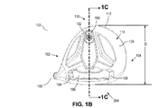
図1A〜1Fは、ヒール側102と、トゥ側104と、クラブフェース108及び打撃フェース109を有する前側106と、後側110と、上面116を有する上側114(クラウンとも呼ばれる)と、底面120を有する底側118(ソール又はソール部分とも呼ばれる)と、ホーゼル(ホーゼル部分とも呼ばれる)150と、ホーゼル軸154と、ホーゼルインサート158と、ライ角168と、を有するゴルフクラブヘッド100を示す。ゴルフクラブヘッド100は、ゴルフクラブヘッドがアドレス位置に位置付けられているときに測定された、幅寸法W、高さ寸法H、及び奥行き寸法Dを有する。ゴルフクラブヘッドのアドレス位置は、ライ角57度のゴルフクラブヘッド、及びクラブヘッドの指定ロフトに調節されたクラブのロフトとして定義される。特に明記しない限り、本明細書に記載されている測定寸法はすべて、ゴルフクラブヘッドがアドレス位置に配向されているときに評価されている。ライ角57度のゴルフクラブヘッドが、前側フェースの観点から視覚的に平らでないように見える場合、「スコアラインライ」と呼ばれる代替のライ角が使用されている可能性がある。スコアラインライは、実質的に水平なフェースのスコアラインが、完全に平坦な地表面に平行であるライ角として定義される。
1A-1F show a
ゴルフクラブヘッド100の幅寸法Wは、5インチを超えることはできず、ゴルフクラブヘッド100の奥行き寸法Dは、幅寸法Wを超えることはできない。ゴルフクラブヘッド100の高さ寸法Hは、2.8インチを超えることはできない。幾つかの実施形態では、奥行き寸法D又は幅寸法Wは、4.4インチ超、4.5インチ超、4.6インチ超、4.7インチ超、4.8インチ超、4.9インチ超、又は4.6インチ〜5インチであってよい。幾つかの実施形態では、高さ寸法Hは、2.7インチ超、2.6インチ超、2.5インチ超、2.4インチ超、2.3インチ超、2.2インチ超、2.1インチ超、2インチ超、1.9インチ超、又は1.8インチ超であってよい。特定の実施形態では、ゴルフクラブヘッド100の高さ寸法Hは、約63.5mm〜71mm(2.5インチ〜2.8インチ)であってよく、幅寸法Wは約116.84mm〜約127mm(4.6インチ〜5.0インチ)であってよく、奥行き寸法Dは約111.76mm〜約127mm(4.4インチ〜5.0インチ)であってよい。
The width dimension W of the
寸法W、D、及びHは、ヒール側102及びトゥ側104、前側106及び後側110、並びに上側114及び底側118の、最も外側の点の垂直突起部間の水平線(図3A〜3Cに示された軸230、240、及び250)上でそれぞれ測定される。ヒール側102の最も外側の点は、アドレス位置において水平地表面140より0.875インチ上にある、ヒール上の点として定義される。図3Bに例として示されているように、前側の最も外側の点は最も前方の点280であってよく、後側110の最も外側の点は最も後方の点282であってよい。Wは、X軸230上で測定される。Dは、Y軸240上で測定される。Hは、Z軸250上で測定される。X軸230及びY軸240は地表面140に平行であり、Z軸250は地表面140に対して直角である。
Dimensions W, D, and H are the horizontal lines between the vertical protrusions at the outermost points of
図1Aは、フェース中心位置136を更に示す。フェース中心位置136は、その全体が参照により本明細書に援用されている、2005年3月25日公開の「USGA Procedure for Measuring the Flexibility of a Golf Clubhead,Revision 2.0」を利用することによって検出される。具体的には、フェース中心位置136は、上記のUSGA文書に記載されている、第6.1.4項及び図6.1に記載されている鋳型法によって検出される。
FIG. 1A further illustrates the
ゴルフクラブヘッド100のCG(重心)位置を測定するための座標系は、フェース中心位置136に位置する。一実施形態では、正の中心フェースX軸130は、クラブヘッド100のヒール側102に向かって投影し、正の中心フェースZ軸134は、クラブヘッド100の上面114に向かって投影し、正の中心フェースY軸132は、地表面140に平行してクラブヘッド100の後側110に向かって投影する。
The coordinate system for measuring the CG (center of gravity) position of the
幾つかの実施形態では、ゴルフクラブヘッド100は、約−5mm〜約10mmのCG x軸座標系、約15mm〜50mmのCG y軸座標系、及び約−10mm〜約5mmのCG z軸座標系を持つCGを有し得る。幾つかの実施形態では、CG y軸座標系は、約20mm〜約50mmであってよい。
In some embodiments, the
幾つかの実施形態では、スコラライン138は、クラブフェース108の打撃フェース109上に位置してよい。幾つかの実施形態では、クラブフェース108上に示されている投影されたCG位置210は、ゴルフクラブヘッド100の「スイートスポット」と見なされる。投影されたCG位置210は、一点上でゴルフクラブヘッド100のバランスを取ることによって検出される。投影されたCG位置210は、概ね、ゴルフクラブヘッド100のクラブフェース108に対して直角な線に沿って投影される。幾つかの実施形態では、投影されたCG位置210は、フェース中心位置136より上に2mm未満、フェース中心位置136より上に1mm未満、又はフェース中心位置136より下に最大1mm又は2mmであってよい。
In some embodiments, the scola lines 138 may be located on the
図1Bは、底側118、及び上側114と底側118との間の縁部112を示す、ゴルフクラブヘッド100の底面図を示す。幾つかの実施形態では、ゴルフクラブヘッド100は、ウェイトポート180と、ウェイトポート180に位置する調節可能なウェイト部182と、が提供されてよい。幾つかの実施形態では、ウェイトポート180及び調節可能なウェイト部182は、その全体が参照により本明細書に援用されている、2008年8月5日に特許を受けた米国特許第7,407,447号に記載されている、ポート及びウェイト部と同一又は類似であってよい。
FIG. 1B shows a bottom view of
幾つかの実施形態では、ゴルフクラブヘッド100は、クラブフェース108に近接したゴルフクラブヘッド100の底側118の前側部分にある、チャネル側壁188を有する陥凹したチャネル部分186を含んでよい。チャネル部分186内の締結具開口部184は、シャフト(例えば、クラブシャフト1104)をゴルフクラブヘッド100に装着するためにホーゼルインサート158と係合させるための、並びに/又は調節可能なロフト角、ライ角、及び/若しくはフェース角を可能にするための、例えばネジなどの機械的締結具163の挿入を可能にするために提供され得る。幾つかの実施形態では、ホーゼルインサート158は、その全体が参照により本明細書に援用されている、2012年11月6日に特許を受けた米国特許第8,303,431号に記載されている、ロフト角、ライ角、又はフェース角のうちの少なくとも1つの調節を可能にするように構成され得る。
In some embodiments,
図1Cは、図1Bの線1C−1Cに沿った断面図を示す。幾つかの実施形態では、機械加工されたフェースインサート190は、ゴルフクラブヘッド100上の前側開口部198に溶接され得る。フェースインサート190は、フェースインサート190の後側表面の中心部分に反転した凹部を有する可変のフェース厚さを有し得る。幾つかの実施形態では、クラウンインサート170は、ゴルフクラブヘッド100の上側114の上面116のすべて又は一部を画定し得る。クラウンインサート170は、ゴルフクラブヘッド100の上側114に接合されてよい。幾つかの実施形態では、クラウンインサート170は、クラウン棚部172の上に載っていてよい。幾つかの実施形態では、クラウンインサート170は、クラウン棚部172に接合されてよい。幾つかの実施形態では、クラウンインサート170は、複合材料を含んでよい。幾つかの実施形態では、クラウンインサート172の複合材料は、複数のプライ又は層を含む、複合レイアップであってよい。
FIG. 1C shows a cross-sectional view along
幾つかの実施形態では、クラウン棚部172は、1〜7mm、1〜5mm、又は1〜3mmの範囲の長さであってよい。幾つかの実施形態では、クラウン棚部172は、ゴルフクラブヘッド100の上側114に形成される開口部173の周囲に連続的に延在してよい。幾つかの実施形態では、クラウン棚部172は、ゴルフクラブヘッド100の上側114に形成される開口部173の周囲の一部に延在してよい。幾つかの実施形態では、クラウン棚部172は、ゴルフクラブヘッド100の上側114に形成される開口部173のすべて又は一部の周りに延在する、複数の断続的な部分を含んでよい。クラウンインサート170及びクラウン棚部172は、本明細書で述べるクラウンインサート442及びクラウン棚部450と同一の要素であると見なされ得る。
In some embodiments, the
幾つかの実施形態では、ゴルフボールとの衝突時のゴルフクラブヘッド100の音を改善するため、複数のリブ194がチャネル部分186の内部に結合されてよい。
In some embodiments, a plurality of
図1Dは、アドレス位置にあるゴルフクラブヘッド100の平面図を示す。ホーゼル平面156は、地表面140に対して直角であり、ホーゼル軸154を包含した状態で示されている。加えて、ホーゼルインサート158によって調節され得る、中心フェースの名目上のフェース角137が示されている。正の通常フェース角は、ゴルフクラブヘッド108が、所定の測定点における中心線ターゲットの右側に位置付けられていることを示す。負の通常フェース角は、ゴルフクラブヘッド108が、所定の測定点における中心線ターゲットの左側に位置付けられていることを示す。トップライン192も、図1Dに示されている。トップライン192は、ゴルフクラブヘッド100の上面116及びクラブフェース108の交点として定義される。幾つかの実施形態では、上面116の塗装線は、トップライン192で停止してよい。
FIG. 1D shows a plan view of
図1D及び1Eは、ゴルフクラブヘッド100の慣性モーメントが、クラブヘッド100がアドレス位置にあるときの地表面140に対して略垂直方向にあるCG200を通って延在するCG Z軸206と、打撃フェース109に略平行及びCG Z軸206に対して略直角であり、ヒール−トゥ方向にCG 200を通って延在するCG X軸202と、CG X軸202及びCG Z軸206に対して略直角であり、前後方向にCG 200を通って延在するCG Y軸204と、を含む、ゴルフクラブヘッド100のCG 200を通って延在する3本の軸を中心に画定され得ることを示す。CG X軸202及びCG Y軸204は両方とも、クラブヘッド100がアドレス位置にあるときに、地表面140に対して略水平方向に延在する。
1D and 1E show that the moment of inertia of the
ゴルフクラブヘッドCG X軸202を中心とした慣性モーメントは、以下の等式で計算される。
![]()
![]()
上の等式1では、yはゴルフクラブヘッドのCG xz平面から無限小質量dmまでの距離であり、zは、ゴルフクラブヘッドCG xy平面から無限小質量dmまでの距離である。ゴルフクラブヘッドCG xz平面は、CG X軸202及びCG Z軸206によって画定される平面である。CG xy平面は、CG X軸202及びCG Y軸204によって画定される平面である。
In
更に、ゴルフクラブヘッドCG Z軸206を中心とした慣性モーメントは、以下の等式で計算される。
![]()
![]()
上の等式2では、xはゴルフクラブヘッドのCG yz平面から無限小質量dmまでの距離であり、yは、ゴルフクラブヘッドCG xz平面から無限小質量dmまでの距離である。ゴルフクラブヘッドCG yz平面は、CG Y軸204及びCG Z軸206によって画定される平面である。
In Equation 2 above, x is the distance from the golf club head CG yz plane to the infinitesimal mass dm, and y is the distance from the golf club head CG xz plane to the infinitesimal mass dm. The golf club head CG yz plane is the plane defined by the CG Y-
特定の実装では、ゴルフクラブヘッド100は、CG Z軸206を中心とした慣性モーメント約450kg・mm2〜約650kg・mm2、CG X軸202を中心とした慣性モーメント約300kg・mm2〜約500kg・mm2、及びCG Y軸204を中心とした慣性モーメント約300kg・mm2〜約500kg・mm2を有し得る。
In a particular implementation,
図1Eは、クラブヘッド100のヒール側面図を示し、正の中心フェースのY軸132の側面図と、CG 200が前述の投影されたCG位置210でクラブフェース108にどのように投影されるかを提供している。名目上の中心フェースのロフト角220は、地表面140に平行する水平面に対して、直角の中心フェースベクトル222によって生じる角度になることが示されている。
FIG. 1E shows a heel side view of the
図1Fは、図1Dに示されている線1F−1Fに沿った断面図を示す。機械的締結具163は、スリーブ160とネジ止めにより係合するために締結具開口部184に挿入することがより簡単に見える。スリーブ160は、ゴルフクラブシャフト(例えば、クラブシャフト1104)がスリーブ160と接着剤接合するために挿入されることを可能にするための、スリーブ孔162を含み得る。幾つかの実施形態では、ホーゼル150又はその一部(例えば、ホーゼルインサート158)は、スリーブ160を受容するように構成されてよい。幾つかの実施形態では、ゴルフクラブヘッド100は、クラブフェース108と上面116との間の遷移部分を強化するため、複数のクラウンリブ196を含んでよい。
FIG. 1F shows a cross-sectional view along the
幾つかの実施形態では、本明細書に記載されているゴルフクラブヘッドは、ロフト角、ライ角、若しくはフェース角を互いに組み合わせて又は互いとは無関係に、調節することが可能な、1つ又は2つ以上のロフト角、ライ角、又はフェース角システムを含んでよい。例えば、ホーゼルインサート158の一部、スリーブ孔162、及びゴルフクラブシャフト(例えば、クラブシャフト1104)は、組み立てられたゴルフクラブの長手方向軸164(図1Fを参照のこと)を集合的に画定する。幾つかの実施形態では、長手方向軸164は、スリーブ孔162と同軸であってよい。スリーブ160の一部は、アセンブリの長手方向軸164に沿ってシャフトをサポートするのに有効であり、長手方向軸164は、ホーゼルチューブ孔152のホーゼル軸154からオフセット角166だけオフセットされる。ホーゼル軸154は、ホーゼルチューブ孔152と同軸である。ホーゼルインサート158は、0.25度の増分で0度〜4度であり得る、単一のオフセット角166を提供し得る。例えば、オフセット角166は、1.0度、1.25度、1.5度、1.75度、2.0度、2.25度、2.5度、2.75度、又は3.0度であり得る。図1Fに示された実施形態のオフセット角166は、1.5度である。幾つかの実施形態では、スリーブ160は、ゴルフクラブヘッド100のロフト角、ライ角、又はフェース角を調節するように位置付けられることが可能であってよい。
In some embodiments, the golf club heads described herein are capable of adjusting loft, lie, or face angles in combination with each other or independent of each other, or It may include more than one loft angle, lie angle, or face angle system. For example, a portion of
図2は、ゴルフクラブヘッド100から取り外したホーゼルインサート158及び機械的締結具163を示す。幾つかの実施形態では、ホーゼルインサート158は、その全体が参照により本明細書に援用されている、2012年11月6日に出願された米国特許第8,303,431号に記載されている、調節可能なホーゼルインサートと同一又は類似であってよい。
FIG. 2 shows
図3A〜3Cは、ゴルフクラブヘッド100に対するX軸230、Y軸240、及びZ軸250を示す。上述のように、軸230、240、及び250は、ゴルフクラブヘッド100の幅W、奥行きD、及び高さHを測定するために使用される。図3A〜3Cはまた、この適用例の目的で中心座標系を画定するため、中心X軸、Y軸、及びZ軸を示す。
3A-
この中心座標系は、クラウンインサートの周縁部(又は壁)と、クラブヘッド本体上の接合壁との間の1つ又は2つ以上の限界寸法を決定するために使用され得る。これらの限界寸法は、クラウンインサートと接合壁との間の接合部を特性化するために使用される。これらの限界寸法は、クラウンインサートと接合壁との間の接合部における、これら2つの間の分離部を決定するために使用される。 This central coordinate system can be used to determine one or more critical dimensions between the periphery (or wall) of the crown insert and the mating wall on the club head body. These critical dimensions are used to characterize the joint between the crown insert and the joint wall. These critical dimensions are used to determine the separation between the two at the joint between the crown insert and the joint wall.
これらの限界寸法を所望の値に調整することは、接合壁とクラウンインサートとの間の接合部における応力集中中心点の形成を阻止するのに役立ち得る。例えば、複数の限界寸法を特定の値以下に調整することは、応力集中の形成を阻止するのに役立ち得る。更に、複数の限界寸法を特定の値以下の点の値における平均変動(average variation)を有するように調整することは、応力集中の形成を阻止するのに役立ち得る。 Adjusting these critical dimensions to desired values can help prevent the formation of stress concentration center points at the joint between the joint wall and the crown insert. For example, adjusting the critical dimensions below a certain value can help prevent the formation of stress concentrations. Moreover, adjusting the critical dimensions to have an average variation in the value of points below a certain value can help prevent the formation of stress concentrations.
応力集中中心部の形成を阻止することは、同様にして、クラウンインサートと接合壁との間の接合部でのこれら2つの接着剤接合におけるひび割れの形成を阻止し得る。接着剤のひび割れは、クラブヘッドの構造的及び/又は視覚的欠陥をもたらし得る。限界寸法を特定の値以下に調整すること、及び/又は特定の値以下の点の間の平均変動を有するように限界寸法を調整することにより、ひび割れを排除することができる。 Preventing the formation of stress-concentrated cores can likewise prevent the formation of cracks in these two adhesive joints at the joint between the crown insert and the joint wall. Adhesive cracks can result in structural and / or visual defects in the club head. By adjusting the critical dimension to below a certain value and / or adjusting the critical dimension to have an average variation between points below a certain value, cracks can be eliminated.
中心Z軸252は、Z軸250と平行し、幅W寸法の中点及び奥行きD寸法の中点(本明細書では以降「中点260」と呼ぶ)で、ゴルフクラブヘッド100の上側114を通って垂直方向に延在する軸として定義される。幅W寸法の中点は、幅W寸法の合計値を2で割った値である。奥行きD寸法の中点は、奥行きD寸法の合計値を2で割った値である。
The central Z-
中心Y軸242は、クラブヘッド100の上面116で中心Z軸252と交差し、Y軸240に平行して延在する軸として定義される。換言すれば、中心Y軸242は、中点260で上面116と交差し、Y軸240に平行して延在する軸によって定義される。中心X軸232は、クラブヘッド100の上面116で中心Z軸252と交差し、X軸230に平行して延在する軸として定義される。換言すれば、中心X軸232は、中点260で上面116と交差し、X軸230に平行して延在する軸によって定義される。
Central Y-
中心X軸、Y軸、及びZ軸は、ゴルフクラブヘッドのクラウンインサートと、ゴルフクラブヘッドの接合壁との間の限界寸法を測定するための、限界点における垂直平面を画定するために使用される。更に、中心X軸及びY軸は、本出願では、ゴルフクラブヘッドのヒール部分、トゥ部分、前側部分、及び後側部分を画定するために使用され得る。図3Cは、クラブヘッド100のヒール部分270、トゥ部分272、前側部分274、及び後側部分276を示す。クラブヘッド100のヒール部分270は、中心Y軸242のヒール側にあるクラブヘッド100の部分によって画定される。クラブヘッド100のトゥ部分272は、中心Y軸242のトゥ側にあるクラブヘッド100の部分によって画定される。クラブヘッド100の前側部分274は、中心X軸232の前側にあるクラブヘッド100の部分によって画定される。クラブヘッド100の後側部分276は、中心X軸232の後側にあるクラブヘッド100の部分によって画定される。
The central X-axis, Y-axis, and Z-axis are used to define a vertical plane at the limit point for measuring the critical dimension between the golf club head crown insert and the golf club head joining wall. It Further, the central X and Y axes may be used in this application to define the heel, toe, front, and back portions of the golf club head. FIG. 3C illustrates the
軸、測定値、部分、及び幾何学的位置(例えば、重心)は、図1A〜1F及び3A〜3Cでゴルフクラブヘッド100に対して示されているが、これらの軸及び測定値は、任意のゴルフクラブヘッド(例えば、ゴルフクラブヘッド400又はゴルフクラブヘッド1000)に適用される。軸の位置及びW、D、Hの測定値は、所定のゴルフクラブヘッドのサイズ及び形状によって異なり得る。
Axes, measurements, portions, and geometrical positions (eg, centers of gravity) are shown for
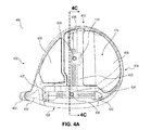
図4A〜4Dは、幾つかの実施形態によるゴルフクラブヘッド400を示す。ゴルフクラブヘッド100と同様に、ゴルフクラブヘッド400は、ヒール側402と、トゥ側404と、クラブフェース408及び打撃フェース409を有する前側406と、後側410と、上面416を有する上側414(クラウンとも呼ばれる)と、底面420を有する底側418(ソール又はソール部分とも呼ばれる)と、ホーゼル(ホーゼル部分とも呼ばれる)430と、ホーゼルインサート432と、を含む。ホーゼルインサート432は、ホーゼルインサート158と同一又は類似であってよい。ゴルフクラブヘッド400は、ゴルフクラブヘッド100に関する上述の寸法と同一又は類似であり得る、幅寸法W、高さ寸法H、及び奥行き寸法Dを有し、ゴルフクラブヘッド100に関する上記の方法と同じ方法で測定され得る。
4A-4D illustrate a
幾つかの実施形態では、ゴルフクラブヘッド400は、1つ又は2つ以上の取り外し可能なシャフト機構を含んでよい。幾つかの実施形態では、ホーゼルインサート432は、ホーゼルインサート158に関して記載されている方法と同じ方法で、ゴルフクラブヘッド400のロフト角、ライ角、又はフェース角のうちの少なくとも1つの調節を可能にするため、取り外し可能なシャフトを含んでよい。幾つかの実施形態では、ゴルフクラブヘッド400は、ゴルフクラブヘッド400に形成される陥凹したチャネル(複数可)436内で摺動するように構成された、1つ又は2つ以上の移動可能なウェイト部434を含む、移動可能なウェイト技術を含んでよい。幾つかの実施形態では、陥凹チャネル436は、ゴルフクラブヘッド400の底側418に形成されてよい。幾つかの実施形態では、クラブフェース408に近接した陥凹チャネル436は、シャフト(例えば、クラブシャフト1104)をゴルフクラブヘッド400に装着するためにホーゼルインサート432と係合させるための、並びに/又は調節可能なロフト角、ライ角、及び/若しくはフェース角を可能にするための、ネジなどの機械的締結具の挿入を可能にするために、締結具開口部437を含んでよい。
In some embodiments,
移動可能なウェイト部434は、移動可能なウェイト部434をクラブヘッド400に取り外し可能に固定するための締結具438を含み得る。締結具438を緩ませると、移動可能なウェイト部434が、陥凹チャネル436内で摺動可能になる。締結具438を締めると、移動可能なウェイト部434が、陥凹チャネル436内の特定の位置に固定され得る。幾つかの実施形態では、陥凹チャネル(複数可)436及び/又は移動可能なウェイト部(複数可)434は、その全体が参照により本明細書に援用されている、2015年7月1日に出願された米国特許出願第14/789,838号に記載されている、チャネル及びウェイト部と同一又は類似であってよい。
幾つかの実施形態では、ゴルフクラブヘッド400は、1つ又は2つ以上の底面パネル/インサート439(ソールパネル/インサートとも呼ばれる)を含み得る。底面パネル439は、クラブヘッド400の底面420の一部を画定し得る。幾つかの実施形態では、底面パネル439は、複合材料を含むパネルであってよい。幾つかの実施形態では、底面パネル(複数可)439の複合材料は、複数のプライ又は層を含む複合レイアップであってよい。幾つかの実施形態では、底面パネル439は、ソール部分に位置する凹部に挿入される。
In some embodiments,
特定の実施形態では、炭素繊維ソールパネル439は、炭素繊維の2つの別個のパネル又は1つの連続的パネルである。炭素繊維ソールパネル439は、本明細書に記載されているクラウン炭素繊維パネル(クラウンインサートとも呼ばれる)と同じレベルの寸法精度を有し得る。クラウン又はソール上の炭素繊維パネルがクラブヘッドの中点にない場合、二次の代替中点は、中心Y軸に沿った又はそれに平行した単一の複合パネルの最大前後寸法と、中心X軸に沿った又はそれに平行した単一の複合パネルの最大ヒール−トゥ寸法と、を測定することによって検出され得る。代替二次中点は、複合パネル(クラウン又はソール上にある)の最大前後寸法の中点と、複合パネルの最大ヒール−トゥ寸法の中点と、の交点として定義される。代替二次中点が確立されると、複合パネルは、クラブヘッドの中心部分にある中点(例えば、中点260)に適用される同一の方法を使用して、一貫性が評価され得る。
In certain embodiments, carbon fiber
複合材料の底面パネル439は、複合材料の高い強度重量特性により、機械的特性を犠牲にすることなく、ゴルフクラブヘッド400の重量を最小限にするのに役立ち得る。底面パネル439に好適な複合材料としては、限定されるものではないが、炭素繊維複合物及び繊維ガラス複合物が挙げられる。幾つかの実施形態では、底面パネル439は、その全体が参照により本明細書に援用されている、2016年8月10日に出願された米国特許出願第15/233,805号に記載されている、パネルと同一又は類似であってよい。
The
クラウン領域又はソール領域のいずれかに位置する複合パネルは、様々な複合材料及びポリマー材料で作製されてよく、熱可塑性材料又は熱硬化性材料のいずれかで作製され得る。幾つかの実施形態では、熱可塑性複合ラミネート材料又は熱可塑性炭素複合ラミネート材料が使用され得る。複合材料は、射出成形材料、熱形成材料、熱硬化性複合材料、又はゴルフクラブヘッドの適用例に好適な他の材料であってよい。 Composite panels located in either the crown region or the sole region may be made of various composite and polymeric materials, and may be made of either thermoplastic or thermoset materials. In some embodiments, a thermoplastic composite laminate material or a thermoplastic carbon composite laminate material may be used. The composite material may be an injection molding material, a thermoforming material, a thermosetting composite material, or other material suitable for golf club head applications.
1つの例示的な材料は、PPS(ポリフェニレンスルフィド)マトリックス又はベース内で長く整列された炭素繊維を有する、熱可塑性の連続的な炭素繊維複合ラミネート材料である。シート形状で製造される、このタイプの材料の1つの商用例は、Lanxess製のTEPEX(登録商標)DYNALITE 207である。材料は、幾つかの実施形態では、42%〜57%の繊維体積を有してよい。幾つかの実施形態では、材料は、200g/m2以下の重量がある。 One exemplary material is a thermoplastic continuous carbon fiber composite laminate material having long aligned carbon fibers within a PPS (polyphenylene sulfide) matrix or base. One commercial example of this type of material, manufactured in sheet form, is TEPEX® DYNALITE 207 from Lanxess. The material may have a fiber volume of 42% to 57% in some embodiments. In some embodiments, the material weighs 200 g / m 2 or less.
幾つかの実施形態では、炭素繊維クラウン又はソールインサート材料は、一方向性炭素繊維材料又はチョップド炭素繊維材料であってよい。熱硬化性プロセスでは、ソール又はクラウンインサートは、加熱されたときに起動する、樹脂及び硬膜剤処方で予備含浸される、織又は一方向性の複合繊維布(炭素繊維など)のプリプレグプライで作製され得る。プリプレグプライは、気泡体又は圧縮型など、熱硬化性プロセスに好適な成形型に置かれ、前後軸に対して0°、+45°、−45°、90°、又は−90°などの異なる方向に配向された炭素繊維又は他の繊維と共にスタック/配向される。一実施形態では、プリプレグシートは、約70g/m2又は40g/m2〜100g/m2の目付を有する擬似等方性レイアップを有する。一実施形態では、プリプレグシート(Newport 301など)を含浸するために使用されるエポキシ樹脂は、約40%又は20%〜80%の樹脂含量(R/C)を有する。 In some embodiments, the carbon fiber crown or sole insert material may be unidirectional carbon fiber material or chopped carbon fiber material. In the thermosetting process, the sole or crown insert is a prepreg ply of woven or unidirectional composite fiber cloth (such as carbon fiber) that is activated when heated and is pre-impregnated with a resin and hardener formulation. Can be made. The prepreg ply is placed in a mold suitable for thermosetting process, such as foam or compression mold, and has different directions such as 0 °, + 45 °, −45 °, 90 °, or −90 ° to the longitudinal axis. Stacked / oriented with carbon fibers or other fibers oriented in the direction. In one embodiment, the prepreg sheet has a quasi-isotropic lay-up having a basis weight of about 70 g / m 2 or 40g / m 2 ~100g / m 2 . In one embodiment, the epoxy resin used to impregnate a prepreg sheet (such as Newport 301) has a resin content (R / C) of about 40% or 20% -80%.
熱硬化性ソール/クラウンインサート用の炭素繊維強化材料は、Grafil,Inc.(Sacramento,California)から入手可能な「34−700」繊維として知られる炭素繊維であってよく、この炭素繊維は、235GPa(34Msi)の引張り弾性率と、4500MPa(650Ksi)の引張り強度を有する。幾つかの実施形態では、引張り弾性率は、100GPaから400GPaであり、引張り強度は2000MPa〜6000MPaである。 Carbon fiber reinforced materials for thermoset sole / crown inserts are available from Grafil, Inc. Carbon fiber known as "34-700" fiber available from (Sacramento, California) having a tensile modulus of 235 GPa (34 Msi) and a tensile strength of 4500 MPa (650 Ksi). In some embodiments, the tensile modulus is 100 GPa to 400 GPa and the tensile strength is 2000 MPa to 6000 MPa.
幾つかの実施形態では、複合レイアップの上部可視層(例えば、図12に示されている上層1210)は、3K織及び編組織であってよく、クラウンインサート又はソールインサートの前側部分にあるインサートの縁部まで延在する。インサート上の様々な限界点にわたって一貫性の高い第1の限界寸法を生成する効果は、上層(織など)の縁部が、上層に顕著な変動を有する(having leaving)ことなく、複合インサート及び本体の交点に明白に位置し得る点にある。
In some embodiments, the upper visible layer of the composite layup (eg,
幾つかの実施形態では、クラブヘッド400の底側418は、底面パネル(複数可)439の少なくとも一部を受容するように構成された1つ又は2つ以上の凹部を画定する、1つ又は2つ以上の棚部及び接合壁を含んでよい。これらの棚部及び接合壁は、本明細書に記載されているクラウン棚部450及び接合壁454と類似の構成を有し得る。更に、底面パネル439は、クラウンインサート442について本明細書で述べた方法と同じ方法で、凹部に位置付けられ得る。例えば、クラブヘッドの底面パネル(複数可)439と底側418との間の接合部(複数可)における限界寸法の測定及び調整は、クラブヘッド400のクラウンインサート442及び上側414について本明細書で述べた方法と同様の方法で実行され得る。
In some embodiments, the
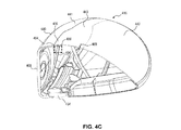
クラブヘッド400の上側414(すなわち、クラウン)は、クラウン部分440及びクラウンインサート442によって画定され得る。クラウン部分440及びクラウンインサート442は、2部エポキシなどの接着剤によって取り付けられた、別個に形成された片であり得る。幾つかの実施形態では、クラウンインサート442は、複合材料を含んでよい。幾つかの実施形態では、クラウンインサート442の複合材料は、複数のプライ又は層を含む複合レイアップであってよい。クラウンインサート442に好適な複合材料としては、限定されるものではないが、上記のように、炭素繊維複合物及び繊維ガラス複合物が挙げられる。幾つかの実施形態では、クラウン又はソールインサートは、限定されるものでないが、アルミニウム、チタン、タングステン、マグネシウム、又はこれらの材料の1つ若しくは2つ以上を含む合金などの、金属材料から構成され得る。幾つかの実施形態では、クラウン又はソールインサートは、プラスチック又は短繊維複合物など、クラブヘッド本体の残部よりも密度の低い材料であってよい。
The upper side 414 (ie, crown) of
幾つかの実施形態では、クラウン部分440は、クラウン棚部450及び接合壁454によって画定されるクラウン凹部領域458(図4Bでは例示の目的で影付きの灰色)を含んでよい。クラウン部分440と組み立てる場合、クラウンインサート442は、クラウン凹部領域458内に少なくとも部分的に配置され得る。幾つかの実施形態では、クラウン凹部領域458は、クラウンインサート442全体を受容してよい。幾つかの実施形態では、クラウン凹部領域458は、クラブヘッド400に形成される開口部490を含んでよい。
In some embodiments, the
接合壁454及びクラウン棚部450は、クラウン凹部領域458の周辺部のすべて又は一部を画定し得る。幾つかの実施形態では、接合壁454及びクラウン棚部450は、中点260を完全に取り囲む(すなわち、中点260を中心に360度回転で放射状に配置された)外周形状を有する、クラウン凹部領域458を画定し得る(例えば、図4Bのクラウン凹部領域458の外周形状を参照のこと)。換言すれば、接合壁454及びクラウン棚部450は、ゴルフクラブヘッド400の上側414に形成される開口部490の周囲に連続的に延在し得る。
Joining
幾つかの実施形態では、接合壁454及びクラウン棚部450は、中点260を部分的にのみ取り囲む外辺形状を有する、クラウン凹部領域458を画定し得る。例えば、クラウン凹部領域458は、クラブヘッド400の前側部分の中点260を取り囲んでよく、クラブヘッド400の後側部分のすべて又は一部は、クラウン凹部領域を欠いていてもよい。換言すれば、接合壁454及びクラウン棚部450は、開口部490の周囲の一部に延在し得る。かかる実施形態では、クラウンインサート442の一部は、クラブヘッド400の一部(クラブヘッド400の後側部分)にあるクラウン部分440の上面441に直接接合され得る。特定の実施形態では、接合壁454は、クラウン凹部領域458の全周辺部の20%未満、30%未満、40%未満、50%未満、70%未満、80%未満、又は90%未満だけ、開口部490の周囲の一部に延在する。
In some embodiments, the
幾つかの実施形態では、接合壁454は、接合壁454を合わせて画定する、複数の別個の接合壁断片455を含み得る。同様に、幾つかの実施形態では、クラウン棚部450は、クラウン棚部450を合わせて画定する、複数の別個のクラウン棚部断片459を含み得る。
In some embodiments, the
クラウン棚部450のクラウン棚部表面452は、クラウン凹部領域458内のクラウンインサート442を支持し得る。幾つかの実施形態では、クラウン棚部表面452は、クラウンインサート442の底面448を支持するために1つ又は2つ以上の突出部453を含んでよい(例えば、図5Aを参照のこと)。幾つかの実施形態では、突出部453は、クラウン棚部表面452で一体に形成されてよい。幾つかの実施形態では、突出部453は、クラウン棚部表面452に固定された(例えば、溶接又は接着による)別個の要素であってもよい。
幾つかの実施形態では、突出部(複数可)453は、0.5mm以下の高さ又は棚部間隙(接合線の厚さとしても知られる)を有してよい。幾つかの実施形態では、高さ470は、0.3mm以下であってよい。幾つかの実施形態では、高さ470は、0.2mm以下であってよい。幾つかの実施形態では、高さ470は、0.1mm以下であってよい。突出部(複数可)453は、底面448をクラウン棚部450に接合する接着剤用の空間を提供するよう、クラウン棚部表面452より上の所望の距離に、クラウンインサート442の底面448を位置付けるのに役立ち得る。幾つかの実施形態では、突出部(複数可)453は存在しない場合があるが、棚部間隙は存在し得る。幾つかの実施形態では、クラウン棚部表面452は、クラウン棚部表面452とクラウンインサート442との間の棚部間隙を画定し得る。例えば、クラウン棚部表面452は、0.3mm又は0.2mm〜0.3mmの棚部間隙を画定し得る。
In some embodiments, the protrusion (s) 453 may have a height or ledge gap (also known as a bond line thickness) of 0.5 mm or less. In some embodiments, the
幾つかの実施形態では、突出部(複数可)453は、クラウン凹部領域458内のクラウンインサート442を水平にするのに役立ち得る(すなわち、クラウンインサート442の周辺壁444及び上面443が、接合壁454及びクラウン部分440の上面441と適切に整列することを確実にするのに役立ち得る)。幾つかの実施形態では、クラウン棚部表面452上の異なる突出部453は、異なる高さ470を有してよい。幾つかの実施形態では、クラウン棚部表面452は、クラウン棚部表面452に沿って延在する単一の突出部453を含んでよい。幾つかの実施形態では、単一のクラウン棚部突出部453は、クラウン棚部表面452に沿って変化する高さ470を有してよい。
In some embodiments, the protrusion (s) 453 may help to level the
幾つかの実施形態では、クラウン棚部450は、増大した長さ451の1つ又は2つ以上の領域を含んでよい。増大した長さ451の領域は、クラブヘッド400のトゥ部分、ヒール部分、前側部分、又は後側部分に位置し得る。非制限的な例として、クラウン棚部450は、増大した長さ451の領域を含む前側部分472を含み得る。増大した長さ451の領域は、接合用により大きい表面積を提供することにより、クラウン棚部450へのクラウンインサート442の接合を容易にし得る。幾つかの実施形態では、増大した長さ451の領域は、クラブヘッド400がゴルフボールを打つときに最大応力を経験する、クラウン414上の領域(複数可)に位置してよい。
In some embodiments,
幾つかの実施形態では、クラウンインサート442を接合壁454及び/又はクラウン棚部450に接合するために、接着剤480が使用されてよい(例えば、図5Aを参照のこと)。好適な接着剤としては、限定されるものではないが、エポキシ樹脂、又は3M(登録商標)製のDP460などの2部エポキシが挙げられる。
In some embodiments, an adhesive 480 may be used to join the
幾つかの実施形態では、クラウンインサート442の上部周縁部445におけるクラウンインサート442の上面443の少なくとも一部は、接合壁454でのクラウン部分440の上面441より垂直距離460の分だけ下に配置されてよい。上面443を上面441より垂直距離460の分だけ下に配置することは、上面443が塗装層でコーティングされた後に、クラウンインサート442とクラウン部分440との間の中間面における平らな表面の形成を容易にし得る。本明細書で使用するとき、用語「平らな」は、少なくともそれぞれの縁部で同じ幾何学的平面を共有する、クラウンインサート442の上面443と、クラウン部分440の上面441と、を指す。幾つかの実施形態では、平らな表面は、+/−0.02mmの偏差内で平らになり得る。クラウンインサート442とクラウン部分440との間の中間面における平らな表面は、クラウン部分440及びクラウンインサート442の材料層及び/又は塗装層として見た目に魅力的になり得ない接着剤480の位置を隠すのに役立ち得る。
In some embodiments, at least a portion of the
幾つかの実施形態では、クラウンインサート又はソールインサートは、ゴルフクラブヘッド本体と異なる塗装又は色である。したがって、クラウンインサート又はソールインサート間の接合間隙(第1の限界寸法などの限界寸法によって測定)は、ユーザーにとって可視である。かかる事例では、クラウンインサート又はソールインサートは、必ずしも平らではなく(+/−0.02超の偏差を有する)、クラウンインサート又はソールインサートと、クラブヘッド本体との間の平らでない表面を可能にすることによって容易な組み立てを促進し得る。 In some embodiments, the crown insert or sole insert is a different paint or color than the golf club head body. Therefore, the joint gap between the crown insert or the sole insert (measured by a critical dimension such as the first critical dimension) is visible to the user. In such cases, the crown insert or sole insert is not necessarily flat (with a deviation of more than +/- 0.02), allowing an uneven surface between the crown insert or sole insert and the club head body. This may facilitate easy assembly.
幾つかの実施形態では、ソール又はクラウン上の直接隣接する本体部分に対して、クラウン/ソールインサート間の色対比は高い。インサートと本体部分との間のL*値が50を超える差を有する場合、暗色から明色への遷移は、「高対比」として定義され得る。幾つかの実施形態では、対比は、10超、20超、30超、又は40超のL*値差として定義される。幾つかの実施形態では、インサートと隣接する本体色との間のL*値は、60超又は65超である。 In some embodiments, the color contrast between the crown / sole insert is high relative to the immediately adjacent body portion on the sole or crown. If the L * value between the insert and the body portion has a difference of more than 50, the transition from dark to light may be defined as "high contrast". In some embodiments, contrast is defined as an L * value difference of greater than 10, greater than 20, greater than 30, or greater than 40. In some embodiments, the L * value between the insert and the adjacent body color is greater than 60 or greater than 65.
実施例も便宜上、L*a*b*色値又はL*C*h色値を使用するCIELab色空間に関して記載されているが、他の色説明を使用することもできる。本明細書で使用するとき、L*は明るさと称され、a*及びb*は色度座標と称され、C*は彩度と称され、hは色相と称される。CIELab色空間では、+a*は赤方向、−a*は緑方向、+b*は黄色方向、及び−b*は青方向である。L*は、完全白色拡散体に対して値100を有する。彩度及び色相は、a*及びb*に関連付けられた極座標であり、彩度(C*)は、a*=b*=0に沿った軸からの距離であり、色相は+a*軸から反時計回りに測定された角度である。以下の説明は概ね、10度での標準光源D65に関連付けられた値に基づいている。この光源は、戸外の昼光照明に似ているが、所望に応じて他の光源を同様に使用することもでき、本明細書で提供する集計データは概ね、10度での光源A及び10度での光源F2の値を含む。これらの光源は、便宜上、D、A、及びFとして簡単に集計データに表記されている。明るさ及び強度という用語が、CIELab座標L*を指すために以下の説明で使用される。 The examples are also described for convenience with reference to the CIELab color space using L * a * b * or L * C * h color values, but other color descriptions can be used. As used herein, L * is called brightness, a * and b * are called chromaticity coordinates, C * is called saturation, and h is called hue. In the CIELab color space, + a * is red, -a * is green, + b * is yellow, and -b * is blue. L * has a value of 100 for a perfect white diffuser. Saturation and hue are polar coordinates associated with a * and b * , saturation (C * ) is the distance from the axis along a * = b * = 0, and hue is from the + a * axis. The angle is measured counterclockwise. The following description is generally based on the values associated with the standard illuminant D65 at 10 degrees. This light source is similar to outdoor daylight illumination, but other light sources can be used as well, as desired, and the aggregate data provided herein is generally at 10 degrees of light sources A and 10. Including the value of the light source F2 in degrees. For convenience, these light sources are simply indicated as D, A, and F in the aggregate data. The terms brightness and intensity are used in the following description to refer to the CIELab coordinates L * .
インサート又は本体上の塗装コーティングの厚さは、塗装される材料のタイプに基づいて異なり得る。例えば、一実施形態では、金属本体は、約45〜60マイクロメートルの合わせた厚さを有するプライマー層及び塗装層、並びに約50〜60マイクロメートルのクリア塗料層によって塗装される。別の実施形態では、複合本体は、約25〜40マイクロメートルの合わせた厚さを有するプライマー層及び塗装層、並びに約30〜40マイクロメートルのクリア塗料層によって塗装される。 The thickness of the paint coating on the insert or body can vary based on the type of material being painted. For example, in one embodiment, the metal body is coated with a primer layer and a coating layer having a combined thickness of about 45-60 micrometers and a clear coating layer of about 50-60 micrometers. In another embodiment, the composite body is coated with a primer layer and a paint layer having a combined thickness of about 25-40 micrometers and a clear paint layer of about 30-40 micrometers.
幾つかの実施形態では、垂直距離460は、0.1mm〜0.3mmの範囲内であってよい。幾つかの実施形態では、垂直距離460は、0.3mm以下であってよい。幾つかの実施形態では、垂直距離460は、0.2mm以下であってよい。幾つかの実施形態では、垂直距離460は、0.1mm以下であってよい。幾つかの実施形態では、垂直距離460は、クラウンインサート442の上面443上に塗装される塗装層の厚さに等しくてよい。幾つかの実施形態では、クラウンインサート442の塗装層は、クラウン部分440の材料又は塗装層とは異なる色及び/又は表面質感を有してよい。
In some embodiments, the
幾つかの実施形態では、垂直距離460は、クラウンインサート442の厚さ468を超える最大高さ462を有する、接合壁454によって生成され得る。幾つかの実施形態では、最大高さ462は、1.0mm〜0.9mmの範囲内であってよい。幾つかの実施形態では、クラウンインサート442の厚さ468は、0.75mm以下であってよい。幾つかの実施形態では、厚さ468は、0.65mm又は1mm以下であってよい。幾つかの実施形態では、クラウンインサート442は、クラウンインサートの厚さ468を画定する6つのプライを備える複合材料で構成され得る。
In some embodiments, the
幾つかの実施形態では、クラウン部分440は、0.2〜1.5mmの範囲内の厚さ474を有し得る。幾つかの実施形態では、クラウン棚部450は、0.5mm〜0.7mmの範囲内の厚さ466を有し得る。幾つかの実施形態では、クラウン棚部450は、1mm〜7.5mm、2mm〜6mm、又は3mm〜5mmの範囲内の長さ464を有し得る。幾つかの実施形態では、クラウン棚部450の増大した長さ451の領域は、5.0mm〜10.0mmの範囲内の長さ464を有し得る。非常に短い、一貫した接合間隙又は第1の限界寸法を有する有意な利点は、棚部長さ464をできるだけ短くすることができ、したがって、クラブヘッドのCG位置を下げるために、クラブヘッドの下部に再配置され得る重量を節減できることにある。
In some embodiments, the
図4Dは、ゴルフクラブヘッド400に関する以下の幾何学的平面を示す。ゴルフクラブヘッド400の中心Z軸と、ゴルフクラブヘッド400の中心Y軸と、によって画定される、第1の垂直平面500。
FIG. 4D shows the following geometrical planes for
第1の垂直平面を、ゴルフクラブヘッド400の中心Z軸の周りで時計回りにθ度回転させることによって画定される、第2の垂直平面502。本出願では、時計回りは、ゴルフクラブヘッドの上側414(すなわち、図4Dに示されている図)に対する時計方向によって定義される。幾つかの実施形態では、θは、1度〜45度の範囲内であってよい。幾つかの実施形態では、θは、2度、3度、4度、5度、10度、20度、又は30度であってよい。
A second vertical plane 502 defined by rotating the first vertical plane θ degrees clockwise about the central Z axis of the
第1の垂直平面500を、ゴルフクラブヘッド400の中心Z軸の周りで反時計回りにθ度回転させることによって画定される、第3の垂直平面504。
A third
ゴルフクラブヘッド400の中心Z軸と、ゴルフクラブヘッド400の中心X軸と、によって画定される、第4の垂直平面506。
A fourth
第4の垂直平面506を、ゴルフクラブヘッド400の中心Z軸の周りで時計回りにβ度回転させることによって画定される、第5の垂直平面508。幾つかの実施形態では、βは、1度〜44度の範囲内であってよい。幾つかの実施形態では、βは、2度、3度、4度、5度、10度、20度、又は30度であってよい。
A fifth
第4の垂直平面506を、ゴルフクラブヘッド400の中心Z軸の周りで反時計回りにβ度回転させることによって画定される、第6の垂直平面510。
A sixth
ゴルフクラブヘッド400の中心Y軸と、ゴルフクラブヘッド400の中心X軸と、によって画定される、X−Y平面512。
An
図4Dはまた、ゴルフクラブヘッド400に関する以下の限界点及び断面を示す。限界点及び断面は、本出願では、限界寸法を測定するために使用される。
FIG. 4D also illustrates the following limits and cross sections for
第1の垂直平面500と、接合壁454の上縁部456との間の交点にある、クラブヘッド400の前側部分に位置する第1の限界点520、及び第1の限界点520において接合壁454に対して直角である垂直平面上で取られた第1の断面550。
A
第2の垂直平面502と、接合壁454の上縁部456との間の交点にある、クラブヘッド400の前側部分に位置する第2の限界点522、及び第2の限界点522において接合壁454に対して直角である垂直平面上で取られた第2の断面552。
A second limit point 522, located at the front portion of the
第3の垂直平面504と、接合壁454の上縁部456との間の交点にある、クラブヘッド400の前側部分に位置する第3の限界点524、及び第3の限界点524において接合壁454に対して直角である垂直平面上で取られた第3の断面554。
A
第5の垂直平面508と、接合壁454の上縁部456との間の交点にある、クラブヘッド400の前側部分に位置する第4の限界点526、及び第4の限界点526において接合壁454に対して直角である垂直平面上で取られた第4の断面556。
A
第6の垂直平面510と、接合壁454の上縁部456との間の交点にある、クラブヘッド400の前側部分に位置する第5の限界点528、及び第5の限界点528において接合壁454に対して直角である垂直平面上で取られた第5の断面558。
A
第4の垂直平面506と、接合壁454の上縁部456との間の交点にある、クラブヘッド400の前側部分に位置する第6の限界点530、及び第6の限界点530において接合壁454に対して直角である垂直平面上で取られた第6の断面560。
A
第4の垂直平面506と、接合壁454の上縁部456との間の交点にある、クラブヘッド400のヒール部分に位置する第7の限界点532、及び第7の限界点532において接合壁454に対して直角である垂直平面上で取られた第7の断面562。
A
第1の垂直平面500と、接合壁454の上縁部456との間の交点にある、クラブヘッド400の後側部分に位置する第8の限界点534、及び第8の限界点534において接合壁454に対して直角である垂直平面上で取られた第8の断面564。
Join at an
第2の垂直平面502と、接合壁454の上縁部456との間の交点にある、クラブヘッド400の後側部分に位置する第9の限界点536、及び第9の限界点536において接合壁454に対して直角である垂直平面上で取られた第9の断面566。
Join at a
第3の垂直平面504と、接合壁454の上縁部456との間の交点にある、クラブヘッド400の後側部分に位置する第10の限界点538、及び第10の限界点538において接合壁454に対して直角である垂直平面上で取られた第10の断面568。
A
第5の垂直平面508と、接合壁454の上縁部456との間の交点にある、クラブヘッド400の後側部分に位置する第11の限界点540、及び第11の限界点540において接合壁454に対して直角である垂直平面上で取られた第11の断面570。
At the intersection between the fifth
第6の垂直平面510と、接合壁454の上縁部456との間の交点にある、クラブヘッド400の後側部分に位置する第12の限界点542、及び第12の限界点542において接合壁454に対して直角である垂直平面上で取られた第12の断面572。
Joining at a
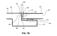
図5A及び5Bは、断面550、552、554、556、558、560、562、564、566、568、570、及び572のいずれかに対応する幾つかの実施形態による、ゴルフクラブヘッド400の断面図を示す。例えば、図5Bに示されているように、それぞれの断面は、接合壁454の上縁部456と、クラウンインサート442の上部周縁部445との間のX−Y平面512に平行して測定される、第1の限界寸法580を有する。換言すれば、第1の限界寸法580は、接合壁454と、クラウンインサート442の上部周縁部445との間の接合間隙を測定する。接合間隙の小さな変動は、可視の接合間隙がゴルファーに示されることを可能にし、それによって、塗装層が接合間隙をマスクする又はカバーすることで、接合間隙の欠陥を隠す必要性を最小限に抑える。一実施形態では、接合間隙は、ユーザーに可視であり、接合間隙領域をカバーする塗装層又はマスキング層を有していない。別の実施形態では、図5A及び5Bは、ソール凹部に位置するソールインサートを有するゴルフクラブヘッドの断面図を示す。
5A and 5B show cross-sections of
幾つかの実施形態では、第1の限界寸法580は、0mm超であってよい(例えば、クラウンインサート442と接合壁454との間の接着剤480の存在による)が、第1の限界寸法580は、特定の値以下であってもよい。幾つかの実施形態では、それぞれの断面の第1の限界寸法580は、Amm以下である。幾つかの実施形態では、Aは、4.0mmに等しくてよい。幾つかの実施形態では、Aは、3.0mmに等しくてよい。幾つかの実施形態では、Aは、2.0mmに等しくてよい。幾つかの実施形態では、Aは、1.0mmに等しくてよい。幾つかの実施形態では、Aは、1.0mm未満であってよい。例えば、Aは、0.9mm、0.8mm、0.7mm、0.6mm、0.5mm、0.4mm、0.3mm、0.2mm、又は0.1mmに等しくてよい。幾つかの実施形態では、Aは、0.6mm〜0.1mmであってよい。
In some embodiments, the first
幾つかの実施形態では、複数の断面550、552、554、556、558、560、562、564、566、568、570、及び572(例えば、2つ以上の断面、又は3つ以上の断面)間の第1の限界寸法580の平均変動は、0.2mm、0.15mm、又は0.1mm以下である。幾つかの実施形態では、すべての断面間の第1の限界寸法580の平均変動は、0.15mm又は0.1mm以下である。幾つかの実施形態では、クラブヘッド400の前側部分に位置する複数の又はすべての断面間の第1の限界寸法580の平均変動は、0.2mm、0.15mm、又は0.1mm以下である。例えば、幾つかの実施形態では、複数の又はすべての断面550、552、554、556、及び558(すなわち、第1の断面550から第5の断面558)間の第1の限界寸法580の平均変動は、0.2mm、0.15mm、又は0.1mm以下である。幾つかの実施形態では、複数の又はすべての断面550、552、554、556、558、560、及び562(すなわち、第1の断面550から第7の断面562)間の第1の限界寸法580の平均変動は、0.2mm、0.15mm、又は0.1mm以下である。
In some embodiments,
幾つかの実施形態では、複数の断面550、552、554、556、558、560、562、564、566、568、570、及び572(例えば、2つ以上の断面、又は3つ以上の断面)間の第1の限界寸法580の平均変動は、0.05mm以下である。幾つかの実施形態では、複数の断面550、552、554、556、558、560、562、564、566、568、570、及び572(例えば、2つ以上の断面、又は3つ以上の断面)間の第1の限界寸法580の平均変動は、部分範囲を含む0.2mm〜0.01mmである。換言すれば、複数の断面間の第1の限界寸法580の平均変動は、0.2mm、0.19mm、0.18mm、0.17mm、0.16mm、0.15mm、0.14mm、0.13mm、0.12mm、0.11mm、0.1mm、0.09mm、0.08mm、0.07mm、0.06mm、0.05mm、0.04mm、0.03mm、0.02mm、若しくは0.01mm、又は端点としてこれらの値のうちのいずれか2つを有する任意の範囲内であってよい。
In some embodiments,
幾つかの実施形態では、複数の断面間の第1の限界寸法580の平均変動は、0.2mm未満、0.15mm未満、0.1mm未満、0.09mm未満、0.08mm未満、0.07mm未満、0.06mm未満、0.05mm未満、0.04mm未満、0.03mm未満、0.02mm未満、又は0.01mm未満であってよい。幾つかの実施形態では、複数の断面間の第1の限界寸法580の平均変動は、0.5mm〜0mm、0.15mm〜0mm、0.2mm〜0mm、0.01mm〜0.09mm、0.02mm〜0.08mm、0.03mm〜0.07mm、又は0.04mm〜0.06mmの範囲内であってよい。
In some embodiments, the average variation of the first
句「2つ以上の断面」は、特定の限界寸法範囲について記載されているが、本明細書に記載されているすべての寸法範囲は、3つ以上の断面、4つ以上の断面、5つ以上の断面、6つ以上の断面、7つ以上の断面、8つ以上の断面、9つ以上の断面、10個以上の断面、11個以上の断面、12個以上の断面、20個以上の断面、40個以上の断面、50個以上の断面、100個以上の断面、200個以上の断面、及び最大360個以上の断面に適用され得ることも考えられることを理解されたい。分析される断面の数は、選択されるβ及びθの値によって異なり得る。 Although the phrase "two or more cross sections" is described for a particular critical dimension range, all size ranges described herein include three or more cross sections, four or more cross sections, and five cross sections. More than 6 sections, more than 6 sections, more than 7 sections, more than 8 sections, more than 9 sections, more than 10 sections, more than 11 sections, more than 12 sections, more than 20 sections It should be understood that it is also possible that it can be applied to cross sections, 40 or more cross sections, 50 or more cross sections, 100 or more cross sections, 200 or more cross sections, and up to 360 or more cross sections. The number of cross sections analyzed may depend on the β and θ values chosen.
下の表1は、一実施形態によるゴルフクラブヘッドの第1の断面550から第5の断面558に関する第1の限界寸法580の平均変動を示す。表1に表すゴルフクラブヘッドについて、Aは1.0mmに等しい。

表1では、それぞれの断面の変動(V)は、特定の断面の限界寸法(CD)と複数の限界寸法の平均との間の差の絶対値に等しい。また、平均変動は、複数の断面に関する変動の平均に等しい。 In Table 1, the variation (V) of each cross section is equal to the absolute value of the difference between the critical dimension (CD) of a particular cross section and the average of multiple critical dimensions. Also, the average variation is equal to the average of the variations for multiple cross sections.
表1では、それぞれの断面のCDは、複数の点にわたる平均CDが結果的に0.848mmとなるように平均化される。したがって、それぞれのCDが0.848mm平均値から差し引かれ、結果的に対応の変動Vになるように絶対値が使用される。それぞれの個体変動Vはまた、「平均変動」変数に平均化され得る。表1は、平均変動値0.0624mmを示す。 In Table 1, the CD of each cross section is averaged so that the average CD across multiple points results in 0.848 mm. Therefore, the absolute value is used so that each CD is subtracted from the 0.848 mm mean value, resulting in a corresponding variation V. Each individual variation V can also be averaged into a "mean variation" variable. Table 1 shows the average variation value of 0.0624 mm.
例えば、図5Bに示されているように、それぞれの断面はまた、接合壁454と、クラウンインサート442の下部周縁部446との間のX−Y平面512に平行して測定される、第2の限界寸法582を有し得る。換言すれば、第2の限界寸法582は、接合壁454と、クラウンインサート442の下部周縁部446との間の接合間隙を測定する。幾つかの実施形態では、第2の限界寸法582は、0mm超であってよい(例えば、クラウンインサート442と接合壁454との間の接着剤480の存在による)が、第2の限界寸法582は、特定の値以下であってもよい。幾つかの実施形態では、それぞれの断面の第2の限界寸法582は、Bmm以下である。Bの値は、Aについて上述したように任意の値であってよい。
For example, as shown in FIG. 5B, each cross section is also measured parallel to the
幾つかの実施形態では、複数の断面550、552、554、556、558、560、562、564、566、568、570、及び572(例えば、2つ以上の断面、又は3つ以上の断面)間の第2の限界寸法582の平均変動は、0.2mm、0.15mm、又は0.1mm以下である。幾つかの実施形態では、すべての断面間の第2の限界寸法582の平均変動は、0.2mm、0.15mm、又は0.1mm以下である。幾つかの実施形態では、クラブヘッド400の前側部分に位置する複数の又はすべての断面間の第2の限界寸法582の平均変動は、0.2mm、0.15mm、又は0.1mm以下である。例えば、幾つかの実施形態では、複数の又はすべての断面550、552、554、556、558(すなわち、第1の断面550から第5の断面558)間の第2の限界寸法582の平均変動は、0.2mm、0.15mm、又は0.1mm以下である。幾つかの実施形態では、複数の又はすべての断面550、552、554、556、558、560、及び562(すなわち、第1の断面550から第7の断面562)間の第2の限界寸法582の平均変動は、0.2mm、0.15mm、又は0.1mm以下である。
In some embodiments,
第2の限界寸法582間の平均変動の値は、第1の限界寸法580間の平均変動に関して上述したように、任意の値であってよい。また、第2の限界寸法582間の平均変動は、第1の限界寸法580の平均変動と同じ方法で計算される。
The value of the average variation between the second
図5Bに例示されているように、それぞれの断面はまた、接合壁454と、クラウンインサート442の周壁444の中点447との間のX−Y平面512に平行して測定される、第3の限界寸法584を有し得る。換言すれば、第3の限界寸法584は、接合壁454と、クラウンインサート442の中点447との間の接合間隙を測定する。幾つかの実施形態では、第3の限界寸法584は、0mm超であってよい(例えば、クラウンインサート442と接合壁454との間の接着剤480の存在による)が、第3の限界寸法584は、特定の値以下であってもよい。幾つかの実施形態では、それぞれの断面の第3の限界寸法584は、Cmm以下である。Cの値は、Aについて上述したように任意の値であってよい。
As illustrated in FIG. 5B, each cross section is also measured parallel to the
幾つかの実施形態では、複数の断面550、552、554、556、558、560、562、564、566、568、570、及び572(例えば、2つ以上の断面、又は3つ以上の断面)間の第3の限界寸法584の平均変動は、0.2mm、0.15mm、又は0.1mm以下である。幾つかの実施形態では、すべての断面間の第3の限界寸法584の平均変動は、0.2mm、0.15mm、又は0.1mm以下である。幾つかの実施形態では、クラブヘッド400の前側部分に位置する複数の又はすべての断面間の第3の限界寸法584の平均変動は、0.2mm、0.15mm、又は0.1mm以下である。例えば、幾つかの実施形態では、複数の又はすべての断面550、552、554、556、558(すなわち、第1の断面550から第5の断面558)間の第3の限界寸法584の平均変動は、0.2mm、0.15mm、又は0.1mm以下である。幾つかの実施形態では、複数の又はすべての断面550、552、554、556、558、560、及び562(すなわち、第1の断面550から第7の断面562)間の第3の限界寸法584の平均変動は、0.2mm、0.15mm、又は0.1mm以下である。
In some embodiments,
第3の限界寸法584間の平均変動の値は、第1の限界寸法580間の平均変動に関して上述したように、任意の値であってよい。また、第3の限界寸法584間の平均変動は、第1の限界寸法580の平均変動と同じ方法で計算される。
The value of the average variation between the third
図5A及び5Bは、ゴルフクラブヘッド400の中心に向かって角度付けされた周壁444及び接合壁454(すなわち、内側に角度付けされた壁)を示す。周壁444及び接合壁454の角度は、例えば、10度であってよい。周壁444及び接合壁454の角度は、周壁444と接合壁454との間の接合部の所望の形状によって異なり得る。様々な非限定的周壁444及び接合壁454の構成が、図6A〜9Bに示されている。他の実施形態では、図5A〜9Bは、ソール凹部に位置するソールインサートを有するゴルフクラブヘッドの断面図を示す。換言すれば、図5A〜9Bに示される接合壁は、クラブヘッド400のソール部分に形成される接合壁であってよく、図5A〜9Bに示されている棚部はソール棚部であってよく、接合壁及び棚部は、底面パネル/インサート439のすべて又は一部を受容するためのソール凹部領域を画定し得る。
5A and 5B show
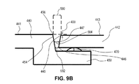
図6A及び6Bは、幾つかの実施形態により、外側に角度付けされた(すなわち、クラブヘッド400のクラブフェース408に向かって角度付けされた)周壁444と、外側に角度付けされた接合壁454と、を示す。図6A及び6Bにおける周壁444及び接合壁454の角度は、例えば、10度であってよい。図7A及び7Bは、幾つかの実施形態による、垂直に真っ直ぐな周壁444及び垂直に真っ直ぐな接合壁454を示す。図8A及び8Bは、幾つかの実施形態による、内側に角度付けされた周壁444及び外側に角度付けされた接合壁454を示す。図9A及び9Bは、外側に角度付けされた周壁444及び内側に角度付けされた接合壁454を示す。図8A〜9Bにおける周壁444及び接合壁454の内側角度及び外側角度は、例えば、10度であってよい。
6A and 6B illustrate a
図10A〜10Dは、幾つかの実施形態によるゴルフクラブヘッド1000を示す。ゴルフクラブヘッド100/400と同様に、ゴルフクラブヘッド1000は、ヒール側1002と、トゥ側1004と、クラブフェース1008及び打撃フェース1009を有する前側1006と、後側1010と、上面1016を有する上側1014(クラウンとも呼ばれる)と、底面1020を有する底側1018(ソール又はソール部分とも呼ばれる)と、ホーゼル1030と、ホーゼルインサート1032と、を含む。ホーゼルインサート1032は、ホーゼルインサート158/432と同一又は類似であってよい。ゴルフクラブヘッド1000は、ゴルフクラブヘッド100について上述した寸法と同一又は類似であり得る、幅寸法W、高さ寸法H、及び奥行き寸法Dを有し、ゴルフクラブヘッド100に関する上記の方法と同じ方法で測定され得る。
10A-10D show a
クラブヘッド1000の上側1014(すなわち、クラウン)は、クラウン部分1040及びクラウンインサート1042によって画定され得る。クラウン部分440及びクラウンインサート442は、クラブヘッド400に関して本明細書で論じたクラウン部分1040及びクラウンインサート1042と同一又は類似であってよい。
The upper side 1014 (ie, crown) of
クラブヘッド400と同様に、クラブヘッド1000は、クラウン棚部1050及び接合壁1054によって画定されるクラウン凹部領域1058(図10Bでは例示の目的で影付きの灰色)を含み得る。クラウン棚部1050及び接合壁1054は、クラウン棚部450及び接合壁454と同一又は類似であってよい。接着剤は、クラブヘッド400に関して上述した方法と同じ方法で、クラウンインサート1042をクラウン棚部1050及び/又は接合壁1054に接合するために使用され得る。更に、クラウンインサート1042の周縁部(又は壁)と接合壁1054との間の限界寸法は、クラブヘッド400に関して本明細書で述べた方法と同じ方法で確定され、測定され得る。
Similar to
幾つかの実施形態では、ゴルフクラブヘッド1000には、ウェイトポート1060と、ウェイトポート1060に位置する調節可能なウェイト部1062と、が提供されてよい。ウェイトポート1060及び調節可能なウェイト部1062は、クラブヘッド100に関して本明細書で述べたウェイトポート180及び調節可能なウェイト部182と同一又は類似であってよい。
In some embodiments,
幾つかの実施形態では、ゴルフクラブヘッド1000は、クラブフェース1008に近接したゴルフクラブヘッド1000の底側1018の前側部分にある、チャネル側壁1072を有する陥凹したチャネル部分1070を含んでよい。チャネル部分1070内の締結具開口部1074は、シャフト(例えば、クラブシャフト1104)をゴルフクラブヘッド1000に装着するためにホーゼルインサート1032と係合させるための、並びに/又は調節可能なロフト角、ライ角、及び/若しくはフェース角を可能にするための、例えばネジなどの機械的締結具1076の挿入を可能にするために提供され得る。
In some embodiments,
幾つかの実施形態では、ゴルフクラブヘッド1000は、1つ又は2つ以上の底面パネル1080を含んでよい。幾つかの実施形態では、底面パネル1080は、複合材料を含むパネルであってよい。底面パネル1080は、クラブヘッド400に関して本明細書で述べた底面パネル439と同一又は類似であってよい。
In some embodiments,
図11は、幾つかの実施形態によるゴルフクラブ1100を示す。ゴルフクラブ1100は、クラブヘッド1102及びクラブシャフト1104を含む。クラブシャフト1104は、ゴルフクラブヘッド1102のホーゼルに連結したグリップ端部1106及びクラブヘッド端部1108を含む。グリップ端部1106は、グリップ1110を含んでよい。ゴルフクラブヘッド1102は、本明細書で述べた任意のクラブヘッド(例えば、クラブヘッド100、400、及び1000)と同一又は類似であってよい。幾つかの実施形態では、ゴルフクラブ1100は、ゴルフクラブヘッド1102のロフト角、ライ角、又はクラブフェース角の少なくとも1つを調節するように構成された、1つ又は2つ以上の取り外し可能なシャフト機構を含んでよい。例えば、ゴルフクラブ1100は、ゴルフクラブヘッド1102のロフト角、ライ角、又はクラブフェース角の少なくとも1つを調節するように構成された、調節可能なホーゼルインサートを含んでよい。幾つかの実施形態では、ゴルフクラブヘッド1102は、ゴルフクラブヘッド1102に形成される陥凹チャネル(複数可)内で摺動するように構成された、1つ又は2つ以上の移動可能ウェイトを含んでよい。
FIG. 11 illustrates a
図12は、断面550、552、554、556、558、560、562、564、566、568、570、及び572のいずれかに対応するゴルフクラブヘッドの断面図を示す。図12は、周壁1202、上部周縁部1204、及び下部周縁部1206を有するクラウンインサート1200を示す。図12はまた、接合壁1222及びクラウン棚部1228を有するクラウン部分1220を示す。
FIG. 12 shows a cross-sectional view of a golf club head corresponding to any of the
図12に示すように、クラウンインサート1200及び/又は接合壁1222の縁部は、幾つかの実施形態では実質的に円形の形状を有してよい。実質的に円形の形状は、クラウン又はソールインサートの厚さの4分の1を超える角部半径として定義される。例えば、半径0.25mmの角部を有する厚さ1mmのインサートは、実質的に円形の形状と見なされ、それゆえ、以下に記載される外挿方法を使用する。上の定義に基づいた実質的に円形の形状が存在しない場合、最上部の可視の縁部が、第1の限界寸法を測定するために使用され、最下部の縁部が第2の限界寸法を測定するために使用される。
As shown in FIG. 12, the edges of
かかる縁部が実質的に円形の形状を有する場合は、図12に、上部周縁部1204、下部周縁部1206、及び第1の限界点1224の位置を決定する方法が示されている。縁部1204及び1206、並びに点1224は、クラウンインサート1200及び接合壁1222が、直角に形成された縁部を有する箇所に位置する。換言すれば、クラウンインサート1200及び/又は接合壁1222の実質的に円形の縁部が、直角の縁部に外挿されて、上部周縁部1204、下部周縁部1206、及び第1の限界点1224の位置が決定される。上部周縁部1204、下部周縁部1206、及び第1の限界点1224の位置を決定した後、第1の限界寸法1230及び第2の限界寸法1232が、第1の限界寸法580及び第2の限界寸法582に関して記載されている方法と同じ方法で測定され得る。
If such an edge has a substantially circular shape, FIG. 12 illustrates a method of determining the location of upper
上記の限界寸法(例えば、第1、第2、及び第3の限界寸法)及び測定値を決定するため、クラウンインサート(例えば、複合クラウンインサート)の断片と、対応する接合壁及び構造と、が、2部エポキシを使用し、LECO製のスプリングクリップ、部品番号810−485と、1:1比のLECO粉液樹脂と、を保持することで、ゴルフクラブヘッドから採取され、円筒形の成形型内でコールドマウント加工され得る。試料は、高解像度表示のために研磨され得る。Keyence VHX−700 F Degital Microscopeなど、200X以上の能力を有する高解像度デジタル顕微鏡が選択されるべきである。 To determine the critical dimensions (eg, first, second, and third critical dimensions) and measurements described above, fragments of crown inserts (eg, composite crown inserts) and corresponding joining walls and structures are Cylindrical mold taken from a golf club head by holding a LECO spring clip, part number 810-485, and a 1: 1 ratio of LECO powder liquid resin using a 2-part epoxy. It can be cold mounted inside. The sample can be polished for high resolution display. A high resolution digital microscope with a 200X or higher capability should be selected, such as the Keyence VHX-700 F Digital Microscope.
幾つかの実施形態では、クラウンインサート(例えば、クラウンインサート1200)は、例えば、上層(例えば、上層1210)を含む複数の層を含んでよい。幾つかの実施形態では、クラウンインサート又はソールインサート(例えば、クラウンインサート170、442、1042、又は1200)の個々の層は、個々の複合プライによって画定されてよい。
In some embodiments, the crown insert (eg, crown insert 1200) may include multiple layers, including, for example, a top layer (eg, top layer 1210). In some embodiments, individual layers of a crown insert or sole insert (eg,
特定の実施形態の前述の説明は、当業者が知識を適用することにより、他の人にも可能である、そのような特定の実施形態を様々な用途に容易に変更及び/又は適合させ、過度の実験をすることなく、本発明の一般的な概念から逸脱することなく、本発明の一般的な性質を完全に明らかにするであろう。したがって、そのような適応及び修正は、本明細書に提示された教示及び指導に基づいて、開示された実施形態の等価物の意味及び範囲内にあることが意図される。本明細書の表現法又は用語法は、本明細書の用語法又は表現法が教示及び指針に照らして当業者によって解釈されるように、説明の目的のためであって限定のためではないことを理解されたい。 The foregoing description of the particular embodiments is readily possible for others to apply the knowledge of a person skilled in the art, easily adapting and / or adapting such particular embodiments to various applications, Without undue experimentation, the general nature of the invention will be fully elucidated without departing from the general concept of the invention. Accordingly, such adaptations and modifications are intended to be within the meaning and range of equivalents of the disclosed embodiments, based on the teaching and guidance presented herein. The phraseology or terminology used herein is for the purpose of description and not limitation, as the terminology or phraseology herein is interpreted by those of skill in the art in light of the teachings and guidelines. I want you to understand.
本発明の広がり及び範囲は、上記の例示的な実施形態のいずれによっても制限されるべきではないが、特許請求の範囲及びそれらの等価物に従ってのみ規定されるべきである。 The breadth and scope of the present invention should not be limited by any of the above exemplary embodiments, but should be defined only according to the claims and their equivalents.
Claims (24)
ゴルフクラブシャフトと、
ホーゼル部分、クラウン、及びソール部分を有するゴルフクラブヘッドであって、
前記クラウンが、前記クラブヘッドの上面を画定し、クラウン部分を備え、前記クラウン部分が、
前記クラウン部分に形成され、クラウン棚部及び接合壁によって画定される、クラウン凹部領域と、
前記クラウン凹部領域内に少なくとも部分的に配置されているクラウンインサートと、を含む、ゴルフクラブヘッドと、
前記ゴルフクラブヘッドのトゥ側から前記ゴルフクラブヘッドのヒール側までのX軸に沿って測定される幅寸法と、
前記ゴルフクラブヘッドの最も前方の点から前記ゴルフクラブヘッドの最も後方の点までのY軸に沿って測定される奥行き寸法と、
前記幅寸法の中点及び前記奥行き寸法の中点で前記クラウンを通って垂直方向に延在する中心Z軸と、
前記クラブヘッドの前記上面で前記中心Z軸と交差し、前記Y軸と平行に延在する、中心Y軸と、
前記クラブヘッドの前記上面で前記中心Z軸と交差し、前記X軸と平行に延在する、中心X軸と、
前記中心Z軸及び前記中心Y軸によって画定される第1の垂直平面と、
前記第1の垂直平面を、前記中心Z軸を中心にして時計回りに30度回転させることによって画定される、第2の垂直平面と、
前記第1の垂直平面を、前記中心Z軸を中心にして反時計回りに30度回転させることによって画定される、第3の垂直平面と、
前記中心Z軸及び前記中心X軸によって画定される、第4の垂直平面と、
前記第4の垂直平面を、前記中心Z軸を中心として時計回りに30度回転させることによって画定される、第5の垂直平面と、
前記第4の垂直平面を、前記中心Z軸を中心として反時計回りに30度回転させることによって画定される、第6の垂直平面と、
前記中心Y軸及び前記中心X軸によって画定されるX−Y平面と、
前記第1の垂直平面と前記接合壁の上縁部との間の交点にある、前記クラブヘッドの前側部分に位置する第1の限界点、及び、前記第1の限界点において前記接合壁に対して直角である垂直平面上に取られた第1の断面と、
前記第2の垂直平面と前記接合壁の前記上縁部との間の交点にある、前記クラブヘッドの前記前側部分に位置する第2の限界点、及び、前記第2の限界点において前記接合壁に対して直角である垂直平面上に取られた第2の断面と、
前記第3の垂直平面と前記接合壁の前記上縁部との間の交点にある、前記クラブヘッドの前記前側部分に位置する第3の限界点、及び、前記第3の限界点において前記接合壁に対して直角である垂直平面上に取られた第3の断面と、
前記第5の垂直平面と前記接合壁の前記上縁部との間の交点にある、前記クラブヘッドの前記前側部分に位置する第4の限界点、及び、前記第4の限界点において前記接合壁に対して直角である垂直平面上に取られた第4の断面と、
前記第6の垂直平面と前記接合壁の前記上縁部との間の交点にある、前記クラブヘッドの前記前側部分に位置する第5の限界点、及び、前記第5の限界点において前記接合壁に対して直角である垂直平面上に取られた第5の断面と、
前記第4の垂直平面と前記接合壁の前記上縁部との間の交点にある、前記クラブヘッドのトゥ部分に位置する第6の限界点、及び、前記第6の限界点において前記接合壁に対して直角である垂直平面上に取られた第6の断面と、
前記第4の垂直平面と前記接合壁の前記上縁部との間の交点にある、前記クラブヘッドのヒール部分に位置する第7の限界点、及び、前記第7の限界点において前記接合壁に対して直角である垂直平面上に取られた第7の断面と、
前記第1の垂直平面と前記接合壁の前記上縁部との間の交点にある、前記クラブヘッドの後側部分に位置する第8の限界点、及び、前記第8の限界点において前記接合壁に対して直角である垂直平面上に取られた第8の断面と、
前記第2の垂直平面と前記接合壁の前記上縁部との間の交点にある、前記クラブヘッドの前記後側部分に位置する第9の限界点、及び、前記第9の限界点において前記接合壁に対して直角である垂直平面上に取られた第9の断面と、
前記第3の垂直平面と前記接合壁の前記上縁部との間の交点にある、前記クラブヘッドの前記後側部分に位置する第10の限界点、及び、前記第10の限界点において前記接合壁に対して直角である垂直平面上に取られた第10の断面と、
前記第5の垂直平面と前記接合壁の前記上縁部との間の交点にある、前記クラブヘッドの前記後側部分に位置する第11の限界点、及び、前記第11の限界点において前記接合壁に対して直角である垂直平面上に取られた第11の断面と、
前記第6の垂直平面と前記接合壁の前記上縁部との間の交点にある、前記クラブヘッドの前記後側部分に位置する第12の限界点、及び、前記第12の限界点において前記接合壁に対して直角である垂直平面上に取られた第12の断面と、
を含み、
それぞれの断面が、前記クラウンインサートと前記接合壁との間の接合間隙を画定し、前記接合壁の前記上縁部と前記クラウンインサートの上部周縁部との間の前記X−Y平面に平行に測定される、第1の限界寸法を有し、それぞれの断面の前記第1の限界寸法がAmm以下であり、7つ以上の前記断面間の前記第1の限界寸法の平均変動が0.2mm以下であり、
前記クラウンインサートは、さらなる機械加工工程を必要とせずに前記第1の限界寸法の前記平均変動が形成されるように、最終的な形状に機械加工され前記クラウン凹部領域に配置され、
前記クラウン棚部が、第1の長さを有する第1の領域と、第2の長さを有する第2の領域と、を含み、
前記第1の長さが、前記ゴルフクラブヘッドの前記Y軸に平行な方向において前記接合壁から前記クラウンの開口まで測定されるものであり、前記第2の長さが、前記ゴルフクラブヘッドの前記Y軸に平行な方向において前記接合壁から前記クラウンの前記開口まで測定されるものであり、
前記第1の長さが前記第2の長さより大きく、
前記第1の領域及び前記第2の領域が、前記ゴルフクラブヘッドの前記前側部分において前記第5の垂直平面と前記第6の垂直平面との間に配置され、
前記Y軸に平行な方向における前記ゴルフクラブヘッドのフェースから前記接合壁までの距離が段状に徐々に小さくなるよう変化することによって、前記第1の長さが前記第2の長さより大きくなっている、ゴルフクラブ。 A grip,
Golf club shaft,
A golf club head having a hosel portion, a crown, and a sole portion,
The crown defines an upper surface of the club head and comprises a crown portion, the crown portion comprising:
A crown recessed region formed in the crown portion and defined by the crown ledge and the joining wall;
A golf club head comprising: a crown insert at least partially disposed within the crown recess region;
A width dimension measured along the X-axis from the toe side of the golf club head to the heel side of the golf club head;
A depth dimension measured along the Y-axis from the frontmost point of the golf club head to the rearmost point of the golf club head;
A central Z-axis extending vertically through the crown at the midpoint of the width dimension and the midpoint of the depth dimension;
A central Y-axis that intersects the central Z-axis on the top surface of the club head and extends parallel to the Y-axis;
A central X axis that intersects the central Z axis on the top surface of the club head and extends parallel to the X axis;
A first vertical plane defined by the central Z axis and the central Y axis;
A second vertical plane defined by rotating the first vertical plane 30 degrees clockwise about the central Z axis;
A third vertical plane defined by rotating the first vertical plane counterclockwise 30 degrees about the central Z axis;
A fourth vertical plane defined by the central Z axis and the central X axis;
A fifth vertical plane defined by rotating the fourth vertical plane 30 degrees clockwise about the central Z axis;
A sixth vertical plane defined by rotating the fourth vertical plane counterclockwise about the central Z axis by 30 degrees;
An XY plane defined by the central Y axis and the central X axis;
A first limit point located at a front portion of the club head at an intersection between the first vertical plane and an upper edge of the joint wall, and the joint wall at the first limit point. A first cross section taken on a vertical plane that is at a right angle to
A second limit point located at the front portion of the club head at an intersection between the second vertical plane and the upper edge of the joint wall, and the joint at the second limit point. A second cross section taken on a vertical plane perpendicular to the wall,
A third limit point located at the front portion of the club head at an intersection between the third vertical plane and the upper edge of the joint wall, and the joint at the third limit point. A third cross section taken on a vertical plane perpendicular to the wall,
A fourth limit point located at the front portion of the club head at an intersection between the fifth vertical plane and the upper edge of the joint wall, and the joint at the fourth limit point. A fourth cross-section taken on a vertical plane perpendicular to the wall,
A fifth limit point located at the front portion of the club head at an intersection between the sixth vertical plane and the upper edge of the joint wall, and the joint at the fifth limit point. A fifth cross section taken on a vertical plane perpendicular to the wall,
A sixth limit point located at the toe portion of the club head at an intersection between the fourth vertical plane and the upper edge of the joint wall, and the joint wall at the sixth limit point. A sixth cross section taken on a vertical plane that is perpendicular to
A seventh limit point located at the heel portion of the club head at an intersection between the fourth vertical plane and the upper edge of the joint wall, and the joint wall at the seventh limit point. A seventh section taken on a vertical plane that is perpendicular to
An eighth limit point located at a rear portion of the club head at an intersection between the first vertical plane and the upper edge of the joint wall, and the joint at the eighth limit point. An eighth cross section taken on a vertical plane that is at right angles to the wall,
A ninth limit point located at the rear portion of the club head at an intersection between the second vertical plane and the upper edge of the joining wall, and at the ninth limit point A ninth cross section taken on a vertical plane that is at a right angle to the joint wall;
A tenth limit point located at the rear portion of the club head at an intersection between the third vertical plane and the upper edge of the joining wall, and at the tenth limit point A tenth cross section taken on a vertical plane that is at a right angle to the junction wall;
At an intersection between the fifth vertical plane and the upper edge of the joining wall, an eleventh limit point located at the rear portion of the club head, and at the eleventh limit point, An eleventh cross section taken on a vertical plane that is at a right angle to the joint wall;
At a twelfth limit point located at the rear portion of the club head at an intersection between the sixth vertical plane and the upper edge of the joining wall, and at the twelfth limit point, A twelfth cross section taken on a vertical plane that is at a right angle to the joint wall;
Including,
Each cross section defines a joint gap between the crown insert and the joint wall and is parallel to the XY plane between the upper edge of the joint wall and an upper peripheral edge of the crown insert. Having a first critical dimension measured, said first critical dimension of each cross section being less than or equal to Amm, and an average variation of said first critical dimension between seven or more said cross sections being 0.2 mm Is
The crown insert further as the machining process the average variation of the first critical dimension without requiring are formed and the final shape is machined arranged in said crown recess area,
The crown ledge includes a first region having a first length and a second region having a second length,
The first length is measured from the joining wall to the opening of the crown in a direction parallel to the Y axis of the golf club head, and the second length is of the golf club head. Is measured from the joint wall to the opening of the crown in a direction parallel to the Y-axis,
The first length is greater than the second length,
The first region and the second region are disposed between the fifth vertical plane and the sixth vertical plane in the front portion of the golf club head,
The distance from the face of the golf club head to the joining wall in the direction parallel to the Y-axis is changed to be gradually reduced, so that the first length becomes larger than the second length. You are a golf club.
前記ソール凹部領域内に少なくとも部分的に配置されているソールインサートと、を更に含む、請求項1から請求項7のいずれかに記載のゴルフクラブ。 A sole recessed region formed in the sole portion and defined by the sole ledge and the joint wall;
The golf club according to claim 1, further comprising a sole insert disposed at least partially within the sole recessed region.
前記クラブヘッドの上面を画定するクラウンであって、
クラウン部分と、
前記クラウン部分に形成され、クラウン棚部及び接合壁によって画定される、クラウン凹部領域と、
前記クラウン凹部領域内に少なくとも部分的に配置されているクラウンインサートと、を含む、クラウンと、
前記ゴルフクラブヘッドのトゥ側から前記ゴルフクラブヘッドの前記ヒール側までのX軸に沿って測定される幅寸法と、
前記ゴルフクラブヘッドの最も前方の点から前記ゴルフクラブヘッドの最も後方の点までのY軸に沿って測定される奥行き寸法と、
前記幅寸法の中点及び前記奥行き寸法の中点で前記クラウンを通って垂直方向に延在する中心Z軸と、
前記クラブヘッドの前記上面で前記中心Z軸と交差し、前記Y軸と平行に延在する、中心Y軸と、
前記クラブヘッドの前記上面で前記中心Z軸と交差し、前記X軸と平行に延在する、中心X軸と、
前記中心Z軸及び前記中心Y軸によって画定される第1の垂直平面と、
前記第1の垂直平面を、前記中心Z軸を中心として時計回りにθ度回転させることによって画定される、第2の垂直平面と、
前記第1の垂直平面を、前記中心Z軸を中心として反時計回りにθ度回転させることによって画定される、第3の垂直平面と、
前記中心Z軸及び前記中心X軸によって画定される、第4の垂直平面と、
前記第4の垂直平面を、前記中心Z軸を中心として時計回りにβ度回転させることによって画定される、第5の垂直平面と、
前記第4の垂直平面を、前記中心Z軸を中心として反時計回りにβ度回転させることによって画定される、第6の垂直平面と、
前記中心Y軸及び前記中心X軸によって画定されるX−Y平面と、
前記第1の垂直平面と前記接合壁の上縁部との間の交点にある、前記クラブヘッドの前側部分に位置する第1の限界点、及び前記第1の限界点において前記接合壁に対して直角である垂直平面上に取られた第1の断面と、
前記第2の垂直平面と前記接合壁の前記上縁部との間の交点にある、前記クラブヘッドの前記前側部分に位置する第2の限界点、及び前記第2の限界点において前記接合壁に対して直角である垂直平面上に取られた第2の断面と、
前記第3の垂直平面と前記接合壁の前記上縁部との間の交点にある、前記クラブヘッドの前記前側部分に位置する第3の限界点、及び前記第3の限界点において前記接合壁に対して直角である垂直平面上に取られた第3の断面と、
前記第5の垂直平面と前記接合壁の前記上縁部との間の交点にある、前記クラブヘッドの前記前側部分に位置する第4の限界点、及び前記第4の限界点において前記接合壁に対して直角である垂直平面上に取られた第4の断面と、
前記第6の垂直平面と前記接合壁の前記上縁部との間の交点にある、前記クラブヘッドの前記前側部分に位置する第5の限界点、及び前記第5の限界点において前記接合壁に対して直角である垂直平面上に取られた第5の断面と、
前記第4の垂直平面と前記接合壁の前記上縁部との間の交点にある、前記クラブヘッドのトゥ部分に位置する第6の限界点、及び、前記第6の限界点において前記接合壁に対して直角である垂直平面上に取られた第6の断面と、
前記第4の垂直平面と前記接合壁の前記上縁部との間の交点にある、前記クラブヘッドのヒール部分に位置する第7の限界点、及び、前記第7の限界点において前記接合壁に対して直角である垂直平面上に取られた第7の断面と、
前記第1の垂直平面と前記接合壁の前記上縁部との間の交点にある、前記クラブヘッドの後側部分に位置する第8の限界点、及び、前記第8の限界点において前記接合壁に対して直角である垂直平面上に取られた第8の断面と、
前記第2の垂直平面と前記接合壁の前記上縁部との間の交点にある、前記クラブヘッドの前記後側部分に位置する第9の限界点、及び、前記第9の限界点において前記接合壁に対して直角である垂直平面上に取られた第9の断面と、
前記第3の垂直平面と前記接合壁の前記上縁部との間の交点にある、前記クラブヘッドの前記後側部分に位置する第10の限界点、及び、前記第10の限界点において前記接合壁に対して直角である垂直平面上に取られた第10の断面と、
前記第5の垂直平面と前記接合壁の前記上縁部との間の交点にある、前記クラブヘッドの前記後側部分に位置する第11の限界点、及び、前記第11の限界点において前記接合壁に対して直角である垂直平面上に取られた第11の断面と、
前記第6の垂直平面と前記接合壁の前記上縁部との間の交点にある、前記クラブヘッドの前記後側部分に位置する第12の限界点、及び、前記第12の限界点において前記接合壁に対して直角である垂直平面上に取られた第12の断面と、
を含み、
それぞれの断面が、前記クラウンインサートと前記接合壁との間の接合間隙を画定し、前記接合壁の前記上縁部と前記クラウンインサートの上部周縁部との間のX−Y平面に平行に測定される、第1の限界寸法を有し、それぞれの断面の前記第1の限界寸法がAmm以下であり、7つ以上の前記断面間の前記第1の限界寸法の平均変動が0.15mm以下であり、
θが1度〜45度の範囲であり、βが1度〜44度の範囲であり、
前記クラウン棚部が、第1の長さを有する第1の領域と、第2の長さを有する第2の領域と、を含み、
前記第1の長さが、前記ゴルフクラブヘッドの前記Y軸に平行な方向において前記接合壁から前記クラウンの開口まで測定されるものであり、前記第2の長さが、前記ゴルフクラブヘッドの前記Y軸に平行な方向において前記接合壁から前記クラウンの前記開口まで測定されるものであり、
前記第1の長さが前記第2の長さより大きく、
前記第1の領域及び前記第2の領域が、前記ゴルフクラブヘッドの前記前側部分において前記第5の垂直平面と前記第6の垂直平面との間に配置され、
前記Y軸に平行な方向における前記ゴルフクラブヘッドのフェースから前記接合壁までの距離が段状に徐々に小さくなるよう変化することによって、前記第1の長さが前記第2の長さより大きくなっている、ゴルフクラブヘッド。 A golf club head,
A crown defining an upper surface of the club head,
Crown part,
A crown recessed region formed in the crown portion and defined by the crown ledge and the joining wall;
A crown including a crown insert that is at least partially disposed within the crown recess region;
A width dimension measured along the X-axis from the toe side of the golf club head to the heel side of the golf club head;
A depth dimension measured along the Y-axis from the frontmost point of the golf club head to the rearmost point of the golf club head;
A central Z-axis extending vertically through the crown at the midpoint of the width dimension and the midpoint of the depth dimension;
A central Y-axis that intersects the central Z-axis on the top surface of the club head and extends parallel to the Y-axis;
A central X axis that intersects the central Z axis on the top surface of the club head and extends parallel to the X axis;
A first vertical plane defined by the central Z axis and the central Y axis;
A second vertical plane defined by rotating the first vertical plane θ degrees clockwise about the central Z axis;
A third vertical plane defined by rotating the first vertical plane counterclockwise about the central Z axis by θ degrees;
A fourth vertical plane defined by the central Z axis and the central X axis;
A fifth vertical plane defined by rotating the fourth vertical plane clockwise by β degrees about the central Z axis;
A sixth vertical plane defined by rotating the fourth vertical plane counterclockwise by β degrees about the central Z-axis;
An XY plane defined by the central Y axis and the central X axis;
A first limit point located at a front portion of the club head at an intersection between the first vertical plane and an upper edge of the joint wall, and with respect to the joint wall at the first limit point A first cross section taken on a vertical plane that is
A second limit point located at the front portion of the club head at an intersection between the second vertical plane and the upper edge of the joint wall, and the joint wall at the second limit point. A second cross section taken on a vertical plane that is perpendicular to
A third limit point located at the front portion of the club head at an intersection between the third vertical plane and the upper edge of the joint wall, and the joint wall at the third limit point. A third cross section taken on a vertical plane that is perpendicular to
A fourth limit point located at the front portion of the club head at an intersection between the fifth vertical plane and the upper edge of the joint wall, and the joint wall at the fourth limit point. A fourth cross section taken on a vertical plane that is perpendicular to
A fifth limit point located at the front portion of the club head at an intersection between the sixth vertical plane and the upper edge of the joint wall, and the joint wall at the fifth limit point. A fifth cross section taken on a vertical plane that is perpendicular to
A sixth limit point located at the toe portion of the club head at an intersection between the fourth vertical plane and the upper edge of the joint wall, and the joint wall at the sixth limit point. A sixth cross section taken on a vertical plane that is perpendicular to
A seventh limit point located at the heel portion of the club head at an intersection between the fourth vertical plane and the upper edge of the joint wall, and the joint wall at the seventh limit point. A seventh section taken on a vertical plane that is perpendicular to
An eighth limit point located at a rear portion of the club head at an intersection between the first vertical plane and the upper edge of the joint wall, and the joint at the eighth limit point. An eighth cross section taken on a vertical plane that is at right angles to the wall,
A ninth limit point located at the rear portion of the club head at an intersection between the second vertical plane and the upper edge of the joining wall, and at the ninth limit point A ninth cross section taken on a vertical plane that is at a right angle to the joint wall;
A tenth limit point located at the rear portion of the club head at an intersection between the third vertical plane and the upper edge of the joining wall, and at the tenth limit point A tenth cross section taken on a vertical plane that is at a right angle to the junction wall;
At an intersection between the fifth vertical plane and the upper edge of the joining wall, an eleventh limit point located at the rear portion of the club head, and at the eleventh limit point, An eleventh cross section taken on a vertical plane that is at a right angle to the joint wall;
At a twelfth limit point located at the rear portion of the club head at an intersection between the sixth vertical plane and the upper edge of the joining wall, and at the twelfth limit point, A twelfth cross section taken on a vertical plane that is at a right angle to the joint wall;
Including,
Each cross section defines a joint gap between the crown insert and the joint wall and is measured parallel to an XY plane between the upper edge of the joint wall and an upper peripheral edge of the crown insert. And having a first critical dimension, wherein the first critical dimension of each cross section is less than or equal to Amm, and an average variation of the first critical dimension between seven or more of the cross sections is less than or equal to 0.15 mm. And
θ is in the range of 1 to 45 degrees, Ri range der of β 1 degrees to 44 degrees,
The crown ledge includes a first region having a first length and a second region having a second length,
The first length is measured from the joining wall to the opening of the crown in a direction parallel to the Y axis of the golf club head, and the second length is of the golf club head. Is measured from the joint wall to the opening of the crown in a direction parallel to the Y-axis,
The first length is greater than the second length,
The first region and the second region are disposed between the fifth vertical plane and the sixth vertical plane in the front portion of the golf club head,
The distance from the face of the golf club head to the joining wall in the direction parallel to the Y-axis is changed to be gradually reduced, so that the first length becomes larger than the second length. Have a golf club head.
ホーゼル部分、クラウン、及びソール部分であって、
前記クラウンが、前記クラブヘッドの上面を画定し、クラウン部分を備え、前記クラウン部分が、
前記クラウン部分に形成され、クラウン棚部及び接合壁によって画定される、クラウン凹部領域と、
前記クラウン凹部領域内に少なくとも部分的に配置されているクラウンインサートと、を含む、クラウン部分を含む、ホーゼル部分、クラウン、及びソール部分と、
前記ゴルフクラブヘッドのトゥ側から前記ゴルフクラブヘッドの前記ヒール側までのX軸に沿って測定される幅寸法と、
前記ゴルフクラブヘッドの最も前方の点から前記ゴルフクラブヘッドの最も後方の点までのY軸に沿って測定される奥行き寸法と、
前記幅寸法の中点及び前記奥行き寸法の中点で前記クラウンを通って垂直方向に延在する中心Z軸と、
前記クラブヘッドの前記上面で前記中心Z軸と交差し、前記Y軸と平行に延在する、中心Y軸と、
前記クラブヘッドの前記上面で前記中心Z軸と交差し、前記X軸と平行に延在する、中心X軸と、
前記中心Z軸及び前記中心Y軸によって画定される第1の垂直平面と、
前記第1の垂直平面を、前記中心Z軸を中心にして時計回りに30度回転させることによって画定される、第2の垂直平面と、
前記第1の垂直平面を、前記中心Z軸を中心にして反時計回りに30度回転させることによって画定される、第3の垂直平面と、
前記中心Z軸及び前記中心X軸によって画定される、第4の垂直平面と、
前記第4の垂直平面を、前記中心Z軸を中心として時計回りに30度回転させることによって画定される、第5の垂直平面と、
前記第4の垂直平面を、前記中心Z軸を中心として反時計回りに30度回転させることによって画定される、第6の垂直平面と、
中心Y軸及び中心X軸によって画定されるX−Y平面と、
前記第1の垂直平面と前記接合壁の上縁部との間の交点にある、前記クラブヘッドの前側部分に位置する第1の限界点、及び前記第1の限界点において前記接合壁に対して直角である垂直平面上に取られた第1の断面と、
前記第2の垂直平面と前記接合壁の前記上縁部との間の交点にある、前記クラブヘッドの前記前側部分に位置する第2の限界点、及び前記第2の限界点において前記接合壁に対して直角である垂直平面上に取られた第2の断面と、
前記第3の垂直平面と前記接合壁の前記上縁部との間の交点にある、前記クラブヘッドの前記前側部分に位置する第3の限界点、及び前記第3の限界点において前記接合壁に対して直角である垂直平面上に取られた第3の断面と、
前記第5の垂直平面と前記接合壁の前記上縁部との間の交点にある、前記クラブヘッドの前記前側部分に位置する第4の限界点、及び前記第4の限界点において前記接合壁に対して直角である垂直平面上に取られた第4の断面と、
前記第6の垂直平面と前記接合壁の前記上縁部との間の交点にある、前記クラブヘッドの前記前側部分に位置する第5の限界点、及び前記第5の限界点において前記接合壁に対して直角である垂直平面上に取られた第5の断面と、を含み、
それぞれの断面が、前記クラウンインサートと前記接合壁との間の接合間隙を画定し、前記接合壁の前記上縁部と前記クラウンインサートの上部周縁部との間の前記X−Y平面に平行に測定される、第1の限界寸法を有し、それぞれの断面の前記第1の限界寸法がAmm以下であり、5つの前記断面間の前記第1の限界寸法の前記平均変動が0.2mm以下であり、
前記クラウンインサートは、さらなる機械加工工程を必要とせずに前記第1の限界寸法の前記平均変動が形成されるように、最終的な形状に機械加工され前記クラウン凹部領域に配置され、
前記クラウン棚部が、第1の長さを有する第1の領域と、第2の長さを有する第2の領域と、を含み、
前記第1の長さが、前記ゴルフクラブヘッドの前記Y軸に平行な方向において前記接合壁から前記クラウンの開口まで測定されるものであり、前記第2の長さが、前記ゴルフクラブヘッドの前記Y軸に平行な方向において前記接合壁から前記クラウンの前記開口まで測定されるものであり、
前記第1の長さが前記第2の長さより大きく、
前記第1の領域及び前記第2の領域が、前記ゴルフクラブヘッドの前記前側部分において前記第5の垂直平面と前記第6の垂直平面との間に配置され、
前記Y軸に平行な方向における前記ゴルフクラブヘッドのフェースから前記接合壁までの距離が段状に徐々に小さくなるよう変化することによって、前記第1の長さが前記第2の長さより大きくなっている、ゴルフクラブヘッド。 A golf club head,
A hosel part, a crown, and a sole part,
The crown defines an upper surface of the club head and comprises a crown portion, the crown portion comprising:
A crown recessed region formed in the crown portion and defined by the crown ledge and the joining wall;
A hosel portion, a crown, and a sole portion, including a crown portion, including a crown insert disposed at least partially within the crown recessed region;
A width dimension measured along the X-axis from the toe side of the golf club head to the heel side of the golf club head;
A depth dimension measured along the Y-axis from the frontmost point of the golf club head to the rearmost point of the golf club head;
A central Z-axis extending vertically through the crown at the midpoint of the width dimension and the midpoint of the depth dimension;
A central Y-axis that intersects the central Z-axis on the top surface of the club head and extends parallel to the Y-axis;
A central X axis that intersects the central Z axis on the top surface of the club head and extends parallel to the X axis;
A first vertical plane defined by the central Z axis and the central Y axis;
A second vertical plane defined by rotating the first vertical plane 30 degrees clockwise about the central Z axis;
A third vertical plane defined by rotating the first vertical plane counterclockwise 30 degrees about the central Z axis;
A fourth vertical plane defined by the central Z axis and the central X axis;
A fifth vertical plane defined by rotating the fourth vertical plane 30 degrees clockwise about the central Z axis;
A sixth vertical plane defined by rotating the fourth vertical plane counterclockwise about the central Z axis by 30 degrees;
An XY plane defined by a central Y axis and a central X axis;
A first limit point located at a front portion of the club head at an intersection between the first vertical plane and an upper edge of the joint wall, and with respect to the joint wall at the first limit point A first cross section taken on a vertical plane that is
A second limit point located at the front portion of the club head at an intersection between the second vertical plane and the upper edge of the joint wall, and the joint wall at the second limit point. A second cross section taken on a vertical plane that is perpendicular to
A third limit point located at the front portion of the club head at an intersection between the third vertical plane and the upper edge of the joint wall, and the joint wall at the third limit point. A third cross section taken on a vertical plane that is perpendicular to
A fourth limit point located at the front portion of the club head at an intersection between the fifth vertical plane and the upper edge of the joint wall, and the joint wall at the fourth limit point. A fourth cross section taken on a vertical plane that is perpendicular to
A fifth limit point located at the front portion of the club head at an intersection between the sixth vertical plane and the upper edge of the joint wall, and the joint wall at the fifth limit point. A fifth cross-section taken on a vertical plane that is perpendicular to
Each cross section defines a joint gap between the crown insert and the joint wall and is parallel to the XY plane between the upper edge of the joint wall and an upper peripheral edge of the crown insert. Measured, having a first critical dimension, said first critical dimension of each cross section being less than or equal to Amm, said average variation of said first critical dimension between five said cross sections being less than or equal to 0.2 mm And
The crown insert further as the machining process the average variation of the first critical dimension without requiring are formed and the final shape is machined arranged in said crown recess area,
The crown ledge includes a first region having a first length and a second region having a second length,
The first length is measured from the joining wall to the opening of the crown in a direction parallel to the Y axis of the golf club head, and the second length is of the golf club head. Is measured from the joint wall to the opening of the crown in a direction parallel to the Y-axis,
The first length is greater than the second length,
The first region and the second region are disposed between the fifth vertical plane and the sixth vertical plane in the front portion of the golf club head,
The distance from the face of the golf club head to the joining wall in the direction parallel to the Y-axis is changed to be gradually reduced, so that the first length becomes larger than the second length. Have a golf club head.
Applications Claiming Priority (2)
| Application Number | Priority Date | Filing Date | Title |
|---|---|---|---|
| US15/370,530 US10463927B2 (en) | 2016-12-06 | 2016-12-06 | Golf club head |
| US15/370,530 | 2016-12-06 |
Related Child Applications (1)
| Application Number | Title | Priority Date | Filing Date |
|---|---|---|---|
| JP2019193182A Division JP7053555B2 (en) | 2016-12-06 | 2019-10-24 | Golf club head |
Publications (2)
| Publication Number | Publication Date |
|---|---|
| JP2018089365A JP2018089365A (en) | 2018-06-14 |
| JP6682494B2 true JP6682494B2 (en) | 2020-04-15 |
Family
ID=62240770
Family Applications (4)
| Application Number | Title | Priority Date | Filing Date |
|---|---|---|---|
| JP2017224222A Active JP6682494B2 (en) | 2016-12-06 | 2017-11-22 | Golf club head |
| JP2019193182A Active JP7053555B2 (en) | 2016-12-06 | 2019-10-24 | Golf club head |
| JP2022058285A Active JP7394908B2 (en) | 2016-12-06 | 2022-03-31 | golf club head |
| JP2023200609A Pending JP2024020556A (en) | 2016-12-06 | 2023-11-28 | golf club head |
Family Applications After (3)
| Application Number | Title | Priority Date | Filing Date |
|---|---|---|---|
| JP2019193182A Active JP7053555B2 (en) | 2016-12-06 | 2019-10-24 | Golf club head |
| JP2022058285A Active JP7394908B2 (en) | 2016-12-06 | 2022-03-31 | golf club head |
| JP2023200609A Pending JP2024020556A (en) | 2016-12-06 | 2023-11-28 | golf club head |
Country Status (2)
| Country | Link |
|---|---|
| US (3) | US10463927B2 (en) |
| JP (4) | JP6682494B2 (en) |
Families Citing this family (8)
| Publication number | Priority date | Publication date | Assignee | Title |
|---|---|---|---|---|
| US10016662B1 (en) * | 2014-05-21 | 2018-07-10 | Taylor Made Golf Company, Inc. | Golf club |
| JP5848840B1 (en) * | 2015-06-05 | 2016-01-27 | ダンロップスポーツ株式会社 | Golf club head |
| US10052530B2 (en) | 2015-06-29 | 2018-08-21 | Taylor Made Golf Company, Inc. | Golf club |
| US11179608B2 (en) | 2015-06-29 | 2021-11-23 | Taylor Made Golf Company, Inc. | Golf club |
| JP6881103B2 (en) * | 2017-07-05 | 2021-06-02 | 住友ゴム工業株式会社 | Golf club head |
| US10576335B2 (en) | 2017-07-20 | 2020-03-03 | Taylor Made Golf Company, Inc. | Golf club including composite material with color coated fibers and methods of making the same |
| CN112316394A (en) * | 2019-07-31 | 2021-02-05 | 大田精密工业股份有限公司 | Golf club head and striking panel thereof |
| US11219803B2 (en) | 2019-08-30 | 2022-01-11 | Taylor Made Golf Company, Inc. | Golf club |
Family Cites Families (92)
| Publication number | Priority date | Publication date | Assignee | Title |
|---|---|---|---|---|
| CA2081687A1 (en) * | 1992-03-12 | 1993-09-13 | Gordon S. Rennie | Golf club driver and method for making |
| US6089070A (en) * | 1995-09-06 | 2000-07-18 | Super Alloy Technologies Pty Ltd. | Method of manufacturing a metal wood golf club head |
| US6001027A (en) * | 1996-08-27 | 1999-12-14 | Teardrop Ram Golf Company | Metalwood golf club |
| US5776011A (en) | 1996-09-27 | 1998-07-07 | Echelon Golf | Golf club head |
| US6354963B1 (en) | 1998-04-10 | 2002-03-12 | Mitsubishi Rayon Co., Ltd. | Golf club head |
| US6575845B2 (en) | 1999-11-01 | 2003-06-10 | Callaway Golf Company | Multiple material golf club head |
| US7491134B2 (en) | 1999-11-01 | 2009-02-17 | Callaway Golf Company | Multiple material golf club head |
| US6565452B2 (en) * | 1999-11-01 | 2003-05-20 | Callaway Golf Company | Multiple material golf club head with face insert |
| US7128661B2 (en) | 1999-11-01 | 2006-10-31 | Callaway Golf Company | Multiple material golf club head |
| US6623378B2 (en) | 2001-06-11 | 2003-09-23 | Taylor Made Golf Company, Inc. | Method for manufacturing and golf club head |
| JP4097666B2 (en) | 2001-10-24 | 2008-06-11 | 横浜ゴム株式会社 | Golf club head |
| JP3762906B2 (en) | 2001-10-24 | 2006-04-05 | 横浜ゴム株式会社 | Golf club head |
| US7037214B2 (en) * | 2001-12-28 | 2006-05-02 | The Yokohama Rubber Co., Ltd. | Hollow golf club head |
| JP3885023B2 (en) | 2001-12-28 | 2007-02-21 | 横浜ゴム株式会社 | Hollow golf club head |
| JP3823085B2 (en) | 2001-12-28 | 2006-09-20 | 横浜ゴム株式会社 | Hollow golf club head |
| US20030134691A1 (en) * | 2002-01-11 | 2003-07-17 | Tinney Stephen H. | Apparatus and method for affixing veneer to the crown of a golf club |
| US6896006B2 (en) | 2002-03-04 | 2005-05-24 | Vyatek Sports, Inc. | Design and manufacturing method for multi-material tube structures |
| US6663503B1 (en) | 2002-05-23 | 2003-12-16 | Royal Collection, Inc. | Golf club head and golf club equipped with said golf club head |
| US7407447B2 (en) * | 2002-11-08 | 2008-08-05 | Taylor Made Golf Company, Inc. | Movable weights for a golf club head |
| US8303431B2 (en) | 2008-05-16 | 2012-11-06 | Taylor Made Golf Company, Inc. | Golf club |
| US8622847B2 (en) * | 2008-05-16 | 2014-01-07 | Taylor Made Golf Company, Inc. | Golf club |
| US20040192468A1 (en) * | 2002-12-02 | 2004-09-30 | Kenji Onoda | Composite metal wood |
| JPWO2004052472A1 (en) | 2002-12-06 | 2006-04-06 | 横浜ゴム株式会社 | Golf club head and golf club |
| US7500925B2 (en) | 2002-12-06 | 2009-03-10 | The Yokohama Rubber Co., Ltd. | Golf club and method of designing hollow golf club head |
| US6969326B2 (en) | 2002-12-11 | 2005-11-29 | Taylor Made Golf Company, Inc. | Golf club head |
| US20040116207A1 (en) | 2002-12-11 | 2004-06-17 | De Shiell Drew T. | Golf club head and method of manufacture |
| JP4319420B2 (en) | 2003-02-04 | 2009-08-26 | Sriスポーツ株式会社 | Golf club head and golf club |
| JP2004242938A (en) | 2003-02-14 | 2004-09-02 | Sumitomo Rubber Ind Ltd | Golf club head |
| TWI222375B (en) * | 2003-05-05 | 2004-10-21 | Fu Sheng Ind Co Ltd | Golf club head and manufacturing method therefor |
| US7874936B2 (en) * | 2007-12-19 | 2011-01-25 | Taylor Made Golf Company, Inc. | Composite articles and methods for making the same |
| US8777776B2 (en) * | 2003-05-21 | 2014-07-15 | Taylor Made Golf Company, Inc. | Golf club head having a composite face insert |
| JP2005058748A (en) * | 2003-07-31 | 2005-03-10 | Sumitomo Rubber Ind Ltd | Golf club head |
| JP4293531B2 (en) | 2003-08-06 | 2009-07-08 | ダイワ精工株式会社 | Golf club head |
| JP4256254B2 (en) | 2003-12-26 | 2009-04-22 | Sriスポーツ株式会社 | Golf club head |
| JP4403084B2 (en) | 2004-03-18 | 2010-01-20 | Sriスポーツ株式会社 | Golf club head |
| US7189165B2 (en) | 2004-03-18 | 2007-03-13 | Sri Sports Limited | Golf club head |
| JP2005270215A (en) | 2004-03-23 | 2005-10-06 | Sri Sports Ltd | Golf club head |
| JP4410594B2 (en) | 2004-03-29 | 2010-02-03 | Sriスポーツ株式会社 | Golf club head |
| JP4335064B2 (en) | 2004-04-20 | 2009-09-30 | Sriスポーツ株式会社 | Golf club head |
| JP4388411B2 (en) | 2004-04-28 | 2009-12-24 | Sriスポーツ株式会社 | Golf club head |
| JP4410606B2 (en) | 2004-06-03 | 2010-02-03 | Sriスポーツ株式会社 | Golf club head |
| US7258625B2 (en) | 2004-09-08 | 2007-08-21 | Nike, Inc. | Golf clubs and golf club heads |
| US7059973B2 (en) | 2004-09-10 | 2006-06-13 | Callaway Golf Company | Multiple material golf club head |
| US7066835B2 (en) | 2004-09-10 | 2006-06-27 | Callaway Golf Company | Multiple material golf club head |
| US7250007B2 (en) * | 2004-09-21 | 2007-07-31 | Fu Sheng Industrial Co, Ltd. | Wood type golf club head |
| JP2006102053A (en) | 2004-10-04 | 2006-04-20 | Bridgestone Sports Co Ltd | Golf club head |
| US7651414B2 (en) | 2004-10-13 | 2010-01-26 | Roger Cleveland Golf Company, Inc. | Golf club head having a displaced crown portion |
| JP4639749B2 (en) | 2004-10-20 | 2011-02-23 | ブリヂストンスポーツ株式会社 | Manufacturing method of golf club head |
| JP2006130065A (en) | 2004-11-05 | 2006-05-25 | Bridgestone Sports Co Ltd | Golf club head |
| JP4634828B2 (en) | 2005-03-10 | 2011-02-16 | Sriスポーツ株式会社 | Golf club head |
| JP4651442B2 (en) | 2005-04-15 | 2011-03-16 | 三菱レイヨン株式会社 | Golf club head |
| US8523705B2 (en) | 2005-04-21 | 2013-09-03 | Cobra Golf Incorporated | Golf club head |
| US7803065B2 (en) | 2005-04-21 | 2010-09-28 | Cobra Golf, Inc. | Golf club head |
| US7938740B2 (en) | 2005-04-21 | 2011-05-10 | Cobra Golf, Inc. | Golf club head |
| US7377860B2 (en) | 2005-07-13 | 2008-05-27 | Acushnet Company | Metal wood golf club head |
| US20130178306A1 (en) * | 2005-04-21 | 2013-07-11 | Cobra Golf Incorporated | Golf club head with separable component |
| US7658686B2 (en) | 2005-04-21 | 2010-02-09 | Acushnet Company | Golf club head with concave insert |
| JP4612526B2 (en) | 2005-10-28 | 2011-01-12 | Sriスポーツ株式会社 | Golf club head |
| JP2007229002A (en) | 2006-02-27 | 2007-09-13 | Sri Sports Ltd | Golf club head |
| JP4871006B2 (en) | 2006-03-14 | 2012-02-08 | Sriスポーツ株式会社 | Golf club head |
| US7585233B2 (en) * | 2006-05-26 | 2009-09-08 | Roger Cleveland Golf Co., Inc. | Golf club head |
| US7575524B2 (en) * | 2006-12-06 | 2009-08-18 | Taylor Made Golf Company, Inc. | Golf clubs and club-heads comprising a face plate having a central recess and flanking recesses |
| US7500926B2 (en) | 2006-12-22 | 2009-03-10 | Roger Cleveland Golf Co., Inc. | Golf club head |
| US7438647B1 (en) * | 2007-04-03 | 2008-10-21 | Callaway Golf Company | Nanocrystalline plated golf club head |
| JP5120878B2 (en) | 2007-09-06 | 2013-01-16 | ダンロップスポーツ株式会社 | Golf club head |
| US7723419B1 (en) * | 2007-09-17 | 2010-05-25 | Ovation Polymer Technology & Engineered Materials, Inc. | Composition providing through plane thermal conductivity |
| JP5401798B2 (en) | 2008-02-08 | 2014-01-29 | 横浜ゴム株式会社 | Golf club head |
| US7806782B2 (en) | 2008-02-12 | 2010-10-05 | Nike, Inc. | Golf clubs and golf club heads having adjustable weight members |
| US7713138B2 (en) | 2008-04-21 | 2010-05-11 | Tomohiko Sato | Wood club |
| WO2009148968A2 (en) * | 2008-06-02 | 2009-12-10 | Callaway Golf Company | A method for constructing a multiple piece golf club head |
| US8062151B2 (en) | 2008-08-15 | 2011-11-22 | Nike, Inc. | Golf club head and system |
| JP5405787B2 (en) | 2008-09-19 | 2014-02-05 | ブリヂストンスポーツ株式会社 | Golf club head |
| US7993216B2 (en) | 2008-11-17 | 2011-08-09 | Nike, Inc. | Golf club head or other ball striking device having multi-piece construction |
| JP5324992B2 (en) | 2009-04-02 | 2013-10-23 | ダンロップスポーツ株式会社 | Golf club head |
| US8157668B2 (en) * | 2009-08-07 | 2012-04-17 | Taylor Made Golf Company, Inc. | Golf club head |
| US8529370B1 (en) | 2009-09-24 | 2013-09-10 | Callaway Golf Company | Golf club head with a compression-molded, thin-walled aft-body |
| US8460123B1 (en) | 2009-09-15 | 2013-06-11 | Callaway Golf Company | Golf club head with a compression-molded, thin-walled aft-body |
| US8328658B2 (en) | 2009-09-30 | 2012-12-11 | Cobra Golf Incorporated | Golf club with rails |
| US10046212B2 (en) * | 2009-12-23 | 2018-08-14 | Taylor Made Golf Company, Inc. | Golf club head |
| US8632419B2 (en) | 2010-03-05 | 2014-01-21 | Callaway Golf Company | Golf club head |
| JP2012110429A (en) | 2010-11-22 | 2012-06-14 | Sri Sports Ltd | Method of manufacturing golf club head |
| JP5756305B2 (en) | 2011-03-02 | 2015-07-29 | ダンロップスポーツ株式会社 | Golf club head and golf club using the same |
| JP5886595B2 (en) | 2011-10-28 | 2016-03-16 | ダンロップスポーツ株式会社 | Golf club head |
| US9205312B2 (en) | 2011-12-27 | 2015-12-08 | Acushnet Company | Golf club having removable weight |
| US8758165B1 (en) * | 2012-02-28 | 2014-06-24 | Callaway Gold Company | Customizable golf club head |
| US8870679B2 (en) * | 2012-05-31 | 2014-10-28 | Nike, Inc. | Golf club assembly and golf club with aerodynamic features |
| US8926450B2 (en) | 2012-06-11 | 2015-01-06 | Bridgestone Sports Co., Ltd. | Golf club head |
| US8849437B2 (en) | 2012-09-25 | 2014-09-30 | Apple Inc. | Adaptive machining for improving assembly fit of consumer electronics |
| US8696491B1 (en) | 2012-11-16 | 2014-04-15 | Callaway Golf Company | Golf club head with adjustable center of gravity |
| US8753224B1 (en) | 2013-02-08 | 2014-06-17 | Callaway Golf Company | Golf club head with improved aerodynamic characteristics |
| USD711993S1 (en) | 2013-04-16 | 2014-08-26 | Cobra Golf Incorporated | Golf club head |
| JP6227312B2 (en) | 2013-07-23 | 2017-11-08 | ダンロップスポーツ株式会社 | Golf club |
-
2016
- 2016-12-06 US US15/370,530 patent/US10463927B2/en active Active
-
2017
- 2017-11-22 JP JP2017224222A patent/JP6682494B2/en active Active
-
2019
- 2019-10-24 JP JP2019193182A patent/JP7053555B2/en active Active
- 2019-11-04 US US16/673,060 patent/US10905923B2/en active Active
-
2021
- 2021-02-01 US US17/164,033 patent/US20210154538A1/en active Pending
-
2022
- 2022-03-31 JP JP2022058285A patent/JP7394908B2/en active Active
-
2023
- 2023-11-28 JP JP2023200609A patent/JP2024020556A/en active Pending
Also Published As
| Publication number | Publication date |
|---|---|
| US20180154224A1 (en) | 2018-06-07 |
| JP2024020556A (en) | 2024-02-14 |
| JP2020022798A (en) | 2020-02-13 |
| US10905923B2 (en) | 2021-02-02 |
| US20210154538A1 (en) | 2021-05-27 |
| JP2018089365A (en) | 2018-06-14 |
| US20200061427A1 (en) | 2020-02-27 |
| JP2022091925A (en) | 2022-06-21 |
| JP7053555B2 (en) | 2022-04-12 |
| US10463927B2 (en) | 2019-11-05 |
| JP7394908B2 (en) | 2023-12-08 |
Similar Documents
| Publication | Publication Date | Title |
|---|---|---|
| JP6682494B2 (en) | Golf club head | |
| US11931631B2 (en) | Golf club head | |
| JP6813601B2 (en) | Golf club head with adjustable weighting system | |
| US20230121941A1 (en) | Multi-component golf club head | |
| US11278771B2 (en) | Golf club head with a body-conforming weight member | |
| US11731014B2 (en) | Golf club | |
| US20150031468A1 (en) | Golf club | |
| US20220288467A1 (en) | Golf club heads | |
| US11701555B2 (en) | Golf club | |
| US20150011327A1 (en) | Golf club | |
| JP6203200B2 (en) | Golf club head having air gap | |
| CN112105424B (en) | Golf club head and method of manufacturing golf club head | |
| JP2024523940A (en) | Golf club head having multi-material structure | |
| JP2019504686A (en) | Golf club head and golf club head manufacturing method | |
| US20230117902A1 (en) | Golf club heads | |
| JP2022541625A (en) | multi-element golf club head |
Legal Events
| Date | Code | Title | Description |
|---|---|---|---|
| A521 | Request for written amendment filed |
Free format text: JAPANESE INTERMEDIATE CODE: A523 Effective date: 20171122 |
|
| A621 | Written request for application examination |
Free format text: JAPANESE INTERMEDIATE CODE: A621 Effective date: 20171122 |
|
| A131 | Notification of reasons for refusal |
Free format text: JAPANESE INTERMEDIATE CODE: A131 Effective date: 20181030 |
|
| A521 | Request for written amendment filed |
Free format text: JAPANESE INTERMEDIATE CODE: A523 Effective date: 20190130 |
|
| A02 | Decision of refusal |
Free format text: JAPANESE INTERMEDIATE CODE: A02 Effective date: 20190625 |
|
| A521 | Request for written amendment filed |
Free format text: JAPANESE INTERMEDIATE CODE: A523 Effective date: 20191024 |
|
| A911 | Transfer to examiner for re-examination before appeal (zenchi) |
Free format text: JAPANESE INTERMEDIATE CODE: A911 Effective date: 20191212 |
|
| TRDD | Decision of grant or rejection written | ||
| A01 | Written decision to grant a patent or to grant a registration (utility model) |
Free format text: JAPANESE INTERMEDIATE CODE: A01 Effective date: 20200225 |
|
| A61 | First payment of annual fees (during grant procedure) |
Free format text: JAPANESE INTERMEDIATE CODE: A61 Effective date: 20200325 |
|
| R150 | Certificate of patent or registration of utility model |
Ref document number: 6682494 Country of ref document: JP Free format text: JAPANESE INTERMEDIATE CODE: R150 |
|
| SG99 | Written request for registration of restore |
Free format text: JAPANESE INTERMEDIATE CODE: R316G99 |
|
| R360 | Written notification for declining of transfer of rights |
Free format text: JAPANESE INTERMEDIATE CODE: R360 |
|
| R360 | Written notification for declining of transfer of rights |
Free format text: JAPANESE INTERMEDIATE CODE: R360 |
|
| R371 | Transfer withdrawn |
Free format text: JAPANESE INTERMEDIATE CODE: R371 |
|
| R250 | Receipt of annual fees |
Free format text: JAPANESE INTERMEDIATE CODE: R250 |
|
| R250 | Receipt of annual fees |
Free format text: JAPANESE INTERMEDIATE CODE: R250 |