JP6682018B2 - System and method for data transfer in a communication system - Google Patents
System and method for data transfer in a communication system Download PDFInfo
- Publication number
- JP6682018B2 JP6682018B2 JP2018563436A JP2018563436A JP6682018B2 JP 6682018 B2 JP6682018 B2 JP 6682018B2 JP 2018563436 A JP2018563436 A JP 2018563436A JP 2018563436 A JP2018563436 A JP 2018563436A JP 6682018 B2 JP6682018 B2 JP 6682018B2
- Authority
- JP
- Japan
- Prior art keywords
- pdcp
- pdcp pdu
- pdu
- nested
- header
- Prior art date
- Legal status (The legal status is an assumption and is not a legal conclusion. Google has not performed a legal analysis and makes no representation as to the accuracy of the status listed.)
- Active
Links
- 238000000034 method Methods 0.000 title claims description 63
- 238000012546 transfer Methods 0.000 title claims description 19
- 230000006854 communication Effects 0.000 title description 58
- 238000004891 communication Methods 0.000 title description 58
- 230000011664 signaling Effects 0.000 claims description 44
- 230000004931 aggregating effect Effects 0.000 claims description 5
- 238000010586 diagram Methods 0.000 description 31
- 238000012545 processing Methods 0.000 description 21
- 230000009471 action Effects 0.000 description 15
- 230000008569 process Effects 0.000 description 15
- 101001055444 Homo sapiens Mediator of RNA polymerase II transcription subunit 20 Proteins 0.000 description 8
- 102100026165 Mediator of RNA polymerase II transcription subunit 20 Human genes 0.000 description 8
- 108091005487 SCARB1 Proteins 0.000 description 8
- 102100037118 Scavenger receptor class B member 1 Human genes 0.000 description 8
- 238000005516 engineering process Methods 0.000 description 8
- 230000005540 biological transmission Effects 0.000 description 5
- 230000006870 function Effects 0.000 description 3
- 230000002776 aggregation Effects 0.000 description 2
- 238000004220 aggregation Methods 0.000 description 2
- 230000001413 cellular effect Effects 0.000 description 2
- 230000000694 effects Effects 0.000 description 2
- 230000007774 longterm Effects 0.000 description 2
- 230000004048 modification Effects 0.000 description 2
- 238000012986 modification Methods 0.000 description 2
- 241001635479 Coris bulbifrons Species 0.000 description 1
- 230000004075 alteration Effects 0.000 description 1
- 230000006399 behavior Effects 0.000 description 1
- 230000007175 bidirectional communication Effects 0.000 description 1
- 230000006835 compression Effects 0.000 description 1
- 238000007906 compression Methods 0.000 description 1
- 230000001419 dependent effect Effects 0.000 description 1
- 238000013461 design Methods 0.000 description 1
- 230000004069 differentiation Effects 0.000 description 1
- 230000036541 health Effects 0.000 description 1
- 230000010354 integration Effects 0.000 description 1
- 238000007726 management method Methods 0.000 description 1
- 239000013307 optical fiber Substances 0.000 description 1
- 238000012913 prioritisation Methods 0.000 description 1
- 239000004984 smart glass Substances 0.000 description 1
- 125000004079 stearyl group Chemical group [H]C([*])([H])C([H])([H])C([H])([H])C([H])([H])C([H])([H])C([H])([H])C([H])([H])C([H])([H])C([H])([H])C([H])([H])C([H])([H])C([H])([H])C([H])([H])C([H])([H])C([H])([H])C([H])([H])C([H])([H])C([H])([H])[H] 0.000 description 1
- 238000006467 substitution reaction Methods 0.000 description 1
- 230000005641 tunneling Effects 0.000 description 1
Images


Classifications
-
- H—ELECTRICITY
- H04—ELECTRIC COMMUNICATION TECHNIQUE
- H04L—TRANSMISSION OF DIGITAL INFORMATION, e.g. TELEGRAPHIC COMMUNICATION
- H04L69/00—Network arrangements, protocols or services independent of the application payload and not provided for in the other groups of this subclass
- H04L69/22—Parsing or analysis of headers
-
- H—ELECTRICITY
- H04—ELECTRIC COMMUNICATION TECHNIQUE
- H04W—WIRELESS COMMUNICATION NETWORKS
- H04W28/00—Network traffic management; Network resource management
- H04W28/02—Traffic management, e.g. flow control or congestion control
- H04W28/0215—Traffic management, e.g. flow control or congestion control based on user or device properties, e.g. MTC-capable devices
- H04W28/0221—Traffic management, e.g. flow control or congestion control based on user or device properties, e.g. MTC-capable devices power availability or consumption
-
- H—ELECTRICITY
- H04—ELECTRIC COMMUNICATION TECHNIQUE
- H04W—WIRELESS COMMUNICATION NETWORKS
- H04W28/00—Network traffic management; Network resource management
- H04W28/02—Traffic management, e.g. flow control or congestion control
- H04W28/0252—Traffic management, e.g. flow control or congestion control per individual bearer or channel
-
- H—ELECTRICITY
- H04—ELECTRIC COMMUNICATION TECHNIQUE
- H04W—WIRELESS COMMUNICATION NETWORKS
- H04W28/00—Network traffic management; Network resource management
- H04W28/02—Traffic management, e.g. flow control or congestion control
- H04W28/06—Optimizing the usage of the radio link, e.g. header compression, information sizing, discarding information
-
- H—ELECTRICITY
- H04—ELECTRIC COMMUNICATION TECHNIQUE
- H04W—WIRELESS COMMUNICATION NETWORKS
- H04W52/00—Power management, e.g. TPC [Transmission Power Control], power saving or power classes
- H04W52/02—Power saving arrangements
- H04W52/0209—Power saving arrangements in terminal devices
- H04W52/0212—Power saving arrangements in terminal devices managed by the network, e.g. network or access point is master and terminal is slave
-
- H—ELECTRICITY
- H04—ELECTRIC COMMUNICATION TECHNIQUE
- H04W—WIRELESS COMMUNICATION NETWORKS
- H04W40/00—Communication routing or communication path finding
- H04W40/24—Connectivity information management, e.g. connectivity discovery or connectivity update
- H04W40/248—Connectivity information update
-
- H—ELECTRICITY
- H04—ELECTRIC COMMUNICATION TECHNIQUE
- H04W—WIRELESS COMMUNICATION NETWORKS
- H04W80/00—Wireless network protocols or protocol adaptations to wireless operation
- H04W80/02—Data link layer protocols
-
- H—ELECTRICITY
- H04—ELECTRIC COMMUNICATION TECHNIQUE
- H04W—WIRELESS COMMUNICATION NETWORKS
- H04W88/00—Devices specially adapted for wireless communication networks, e.g. terminals, base stations or access point devices
- H04W88/02—Terminal devices
- H04W88/04—Terminal devices adapted for relaying to or from another terminal or user
-
- Y—GENERAL TAGGING OF NEW TECHNOLOGICAL DEVELOPMENTS; GENERAL TAGGING OF CROSS-SECTIONAL TECHNOLOGIES SPANNING OVER SEVERAL SECTIONS OF THE IPC; TECHNICAL SUBJECTS COVERED BY FORMER USPC CROSS-REFERENCE ART COLLECTIONS [XRACs] AND DIGESTS
- Y02—TECHNOLOGIES OR APPLICATIONS FOR MITIGATION OR ADAPTATION AGAINST CLIMATE CHANGE
- Y02D—CLIMATE CHANGE MITIGATION TECHNOLOGIES IN INFORMATION AND COMMUNICATION TECHNOLOGIES [ICT], I.E. INFORMATION AND COMMUNICATION TECHNOLOGIES AIMING AT THE REDUCTION OF THEIR OWN ENERGY USE
- Y02D30/00—Reducing energy consumption in communication networks
- Y02D30/70—Reducing energy consumption in communication networks in wireless communication networks
Description
[関連出願の参照]
本出願は、2016年6月3日に出願され、かつ「System and Method for Data Forwarding in a Communications System」と題する米国非仮特許出願第15/172,618号の優先権を主張し、その全体が再現されているかのように、参照により本明細書に組み込まれるものとする。
[Reference of related application]
This application claims priority to United States Nonprovisional Patent Application No. 15 / 172,618, filed June 3, 2016, and entitled "System and Method for Data Forwarding in a Communications System", in its entirety. Are reproduced by way of reference, and are hereby incorporated by reference.
本開示は、一般にデジタル通信に関し、特に、通信システムにおけるデータ転送のためのシステムおよび方法に関する。 The present disclosure relates generally to digital communications, and more particularly to systems and methods for data transfer in communication systems.
遠隔デバイスは、典型的には、埋め込み型電子機器、ソフトウェア、センサ、ならびに対象がオペレータ、製造業者、ユーザ、および/または他の接続対象と情報を交換できるようにする接続性を有する対象である。遠隔デバイスは、通常小型でバッテリ駆動である。一例として、検知作業(例えば、天気、火災、警備、健康、自動車など)に使用される遠隔デバイスは、電池交換またはユーザの介入なしに数年間動作することが期待される。したがって、バッテリ寿命は重要な考慮事項である。 Remote devices are typically embedded electronics, software, sensors, and objects with connectivity that allow the object to exchange information with operators, manufacturers, users, and / or other connected objects. . Remote devices are typically small and battery powered. As an example, remote devices used for sensing tasks (eg, weather, fire, security, health, automobiles, etc.) are expected to operate for several years without battery replacement or user intervention. Therefore, battery life is an important consideration.
遠隔デバイスは接続されているが、それらの接続性は通常、消費電力を最小限に抑えるために、PC5、BlueTooth(登録商標)(BT)、デバイス間(D2D)、近接サービス(ProSe)などの短距離技術に制限されている。したがって、遠隔配置されたデバイスおよび/またはサービスのために、遠隔デバイスとの間で通信を中継する中間デバイスが必要である。 The remote devices are connected, but their connectivity is typically in order to minimize power consumption, such as PC5, BlueTooth® (BT), device-to-device (D2D), proximity service (ProSe), etc. Limited to short-range technology. Therefore, there is a need for intermediate devices that relay communication with remote devices for remotely located devices and / or services.
例示的な実施形態は、通信システムにおけるデータ転送のためのシステムおよび方法を提供する。 Example embodiments provide systems and methods for data transfer in a communication system.
例示的な実施形態によると、送信デバイスを動作させるための方法が提供される。本方法は、送信デバイスによって、第1の遠隔デバイス(RD)に関連付けられた第1のパケットデータコンバージェンスプロトコル(PDCP)プロトコルデータユニット(PDU)を受信するステップであって、第1のPDCP PDUは少なくとも第1のPDCPヘッダを含む、ステップと、送信デバイスによって、第1のPDCP PDUに従って第1のネスト化されたPDCP PDUを生成するステップであって、第1のネスト化されたPDCP PDUは、第2のPDCPヘッダと第1のPDCP PDUとを含み、第2のPDCPヘッダは、第1のネスト化されたPDCP PDUが第1の中継されたPDCP PDUを含むことを示す第1のPDUタイプインジケータと、第1のRDに関連付けられた第1の識別子とを含む、ステップと、送信デバイスによって、無線ベアラ上で第1のネスト化されたPDCP PDUを送信するステップとを含む。 According to an exemplary embodiment, a method for operating a transmitting device is provided. The method comprises receiving by a transmitting device a first Packet Data Convergence Protocol (PDCP) Protocol Data Unit (PDU) associated with a first remote device (RD), the first PDCP PDU being Generating at least a first nested PDCP PDU according to the first PDCP PDU by the transmitting device, the method including at least a first PDCP header, the first nested PDCP PDU comprising: and a second PDCP header and first PDCP PDU, the second PDCP header is first PDU to indicate that the first nested PDCP PDU includes a first relayed PDCP PD U including a type indicator, and a first identifier associated with the first RD, stearyl And flop, by the transmitting device, and sending the first nested PDCP PDU on the radio bearer.
任意選択的に、前述の実施形態のいずれかによると、本方法は、送信デバイスによって、第2のPDCP PDUを受信するステップであって、第2のPDCP PDUは少なくとも第3のPDCPヘッダを含む、ステップと、送信デバイスによって、第2のPDCP PDUに従って第2のネスト化されたPDCP PDUを生成するステップと、送信デバイスによって、第2のネスト化されたPDCP PDUを第1のネスト化されたPDCP PDUと一緒に無線ベアラ上で送信するステップとをさらに含む。 Optionally, according to any of the previous embodiments, the method comprises the step of receiving a second PDCP PDU by a transmitting device, the second PDCP PDU including at least a third PDCP header. Generating a second nested PDCP PDU according to the second PDCP PDU by the transmitting device, and the second nested PDCP PDU being first nested by the transmitting device, Transmitting on a radio bearer with a PDCP PDU.
任意選択的に、前述の実施形態のいずれかによると、本方法では、第2のネスト化されたPDCP PDUを第1のネスト化されたPDCP PDUと一緒に送信するステップは、送信デバイスによって、第1のネスト化されたPDCP PDUおよび第2のPDCP PDUを集約するステップと、送信デバイスによって、集約された第1および第2のネスト化されたPDCP PDUを無線ベアラ上で送信するステップとを含む。 Optionally, according to any of the previous embodiments, the method comprises the step of transmitting the second nested PDCP PDU with the first nested PDCP PDU by the transmitting device. Aggregating the first nested PDCP PDU and the second PDCP PDU, and transmitting the aggregated first and second nested PDCP PDUs on a radio bearer by a transmitting device. Including.
任意選択的に、前述の実施形態のいずれかによると、本方法では、第2のPDCP PDUは第2のRDから受信され、第2のネスト化されたPDCP PDUは、第4のPDCPヘッダと第2のPDCP PDUとを含み、第4のPDCPヘッダは、第2のネスト化されたPDCP PDUが第2の中継されたPDCP PDUを含むことを示す第2のPDUタイプインジケータと、第2のRDに関連付けられた第2の識別子とを含む。 Optionally, according to any of the previous embodiments, in the method, the second PDCP PDU is received from the second RD and the second nested PDCP PDU is combined with a fourth PDCP header. and a second PDCP PDU, fourth PDCP header, and a second PDU type indicator indicating that the second nested PDCP PDU includes a second relayed PDCP PD U, second Second identifier associated with the RD .
任意選択的に、前述の実施形態のいずれかによると、本方法では、第1のRDと第2のRDは同一である。 Optionally, according to any of the previous embodiments, in the method the first RD and the second RD are the same.
任意選択的に、前述の実施形態のいずれかによると、本方法では、無線ベアラはデータ無線ベアラ(DRB)である。 Optionally, according to any of the previous embodiments, in the method, the radio bearer is a data radio bearer (DRB).
任意選択的に、前述の実施形態のいずれかによると、本方法では、第1のPDCP PDUは制御プレーントラフィックを含み、第1のPDCPヘッダは、第1のネスト化されたPDCP PDUを送信するために使用されるSRBを識別するシグナリング無線ベアラ(SRB)インジケータを含む。 Optionally, according to any of the previous embodiments, in the method, the first PDCP PDU comprises control plane traffic and the first PDCP header sends the first nested PDCP PDU. Includes a signaling radio bearer (SRB) indicator that identifies the SRB used for.
任意選択的に、前述の実施形態のいずれかによると、本方法では、無線ベアラはシグナリング無線ベアラ(SRB)であって、第1のPDCPヘッダは、第1のPDCP PDUが制御プレーントラフィックを含むことを示す第1の転送インジケータを含み、第2のPDCPヘッダは、第1のネスト化されたPDCP PDUが中継されたコントロールプレーントラフィックを含むことを示す第2の転送インジケータを含む。 Optionally, according to any of the previous embodiments, in the method, the radio bearer is a signaling radio bearer (SRB) and the first PDCP header contains the control plane traffic for the first PDCP PDU. And a second PDCP header that includes a second forwarding indicator that indicates that the first nested PDCP PDU includes relayed control plane traffic.
別の例示的な実施形態によると、受信デバイスを動作させるための方法が提供される。本方法は、受信デバイスによって、無線ベアラ上の第1のRDに関連付けられた第1のネスト化されたPDCP PDUを受信するステップであって、第1のネスト化されたPDCP PDUは、第1のPDCPヘッダと第1のPDCP PDUとを含み、第1のPDCPヘッダは、第1のネスト化されたPDCP PDUが第1の中継されたPDCP PDUを含むことを示す第1のPDUタイプインジケータと、第1のRDに関連付けられた第1の識別子とを含む、ステップと、受信デバイスによって、第1のPDCP PDUを第1のPDCP PDUの対象とする受信者に送信するステップとを含む。 According to another exemplary embodiment, a method for operating a receiving device is provided. The method comprises receiving by a receiving device a first nested PDCP PDU associated with a first RD on a radio bearer, the first nested PDCP PDU being the first nested PDCP PDU. include the PDCP header and the first PDCP PDU, the first PDCP header is first PDU type indicator indicating that the first nested PDCP PDU includes a first relayed PDCP PD U And a first identifier associated with the first RD, and, by a receiving device, transmitting the first PDCP PDU to an intended recipient of the first PDCP PDU.
任意選択的に、前述の実施形態のいずれかによると、本方法では、第1のPDCP PDUを送信するステップは、第1のPDCPヘッダを送信するステップをさらに含む。 Optionally, according to any of the previous embodiments, in the method, transmitting the first PDCP PDU further comprises transmitting a first PDCP header.
任意選択的に、前述の実施形態のいずれかによると、本方法は、受信デバイスによって、無線ベアラ上の第2のRDに関連付けられた第2のネスト化されたPDCP PDUを受信するステップであって、第2のネスト化されたPDCP PDUは、第2のPDCPヘッダと第2のPDCP PDUとを含み、第2のPDCPヘッダは、第2のネスト化されたPDCP PDUが第2の中継されたPDCP PDUを含むことを示す第2のPDUタイプインジケータと、第2のRDに関連付けられた第2の識別子とを含み、第1のネスト化されたPDCP PDUおよび第2のPDCP PDUは一緒に集約される、ステップをさらに含む。 Optionally, according to any of the previous embodiments, the method is the step of receiving by the receiving device a second nested PDCP PDU associated with a second RD on the radio bearer. And the second nested PDCP PDU includes a second PDCP header and a second PDCP PDU, the second PDCP header being a second relayed version of the second nested PDCP PDU. and a second PDU type indicator that includes a PDCP PD U, and a second identifier associated with the second RD, the first nested PDCP PDU and the second PDCP PDU are together The method further includes the steps of:
任意選択的に、前述の実施形態のいずれかによると、本方法では、無線ベアラはデータ無線ベアラ(DRB)である。 Optionally, according to any of the previous embodiments, in the method, the radio bearer is a data radio bearer (DRB).
任意選択的に、前述の実施形態のいずれかによると、本方法では、無線ベアラはシグナリング無線ベアラ(SRB)であり、第1のPDCP PDUは、第1のPDCP PDUが制御プレーントラフィックを含むことを示す第1の転送インジケータを含み、第1のPDCPヘッダは、第1のネスト化されたPDCP PDUが中継されたコントロールプレーントラフィックを含むことを示す第2の転送インジケータを含む。 Optionally, according to any of the previous embodiments, in the method, the radio bearer is a signaling radio bearer (SRB) and the first PDCP PDU comprises the first PDCP PDU comprising control plane traffic. , And the first PDCP header includes a second forwarding indicator that indicates that the first nested PDCP PDU includes relayed control plane traffic.
別の例示的な実施形態によると、送信デバイスが提供される。送信デバイスは、プロセッサと、プロセッサにより実行されるプログラミングを格納するコンピュータ可読記憶媒体とを備える。プログラミングは、第1のRDに関連付けられた第1のPDCP PDUを受信し、第1のPDCP PDUは少なくとも第1のPDCPヘッダを含み、第1のPDCP PDUに従って第1のネスト化されたPDCP PDUを生成し、第1のネスト化されたPDCP PDUは、第2のPDCPヘッダと第1のPDCP PDUとを含み、第2のPDCPヘッダは、第1のネスト化されたPDCP PDUが第1の中継されたPDCP PDUを含むことを示す第1のPDUタイプインジケータと、第1のRDに関連付けられた第1の識別子とを含み、また無線ベアラ上で第1のネスト化されたPDCP PDUを送信するように送信デバイスを設定する命令を含む。 According to another exemplary embodiment, a transmitting device is provided. The transmitting device comprises a processor and a computer-readable storage medium storing programming executed by the processor. The programming receives a first PDCP PDU associated with a first RD, the first PDCP PDU including at least a first PDCP header, and a first nested PDCP PDU according to the first PDCP PDU. And the first nested PDCP PDU includes a second PDCP header and a first PDCP PDU, and the second PDCP header includes the first nested PDCP PDU. a first PDU type indicator that includes a relayed PDCP PD U, and a first identifier associated with the first RD, also the first nested PDCP PDU on the radio bearer Includes instructions for configuring the transmitting device to transmit.
任意選択的に、前述の実施形態のいずれかによると、送信デバイスでは、プログラミングは第2のPDCP PDUを受信し、第2のPDCP PDUは少なくとも第3のPDCPヘッダを含み、第2のPDCP PDUに従って第2のネスト化されたPDCP PDUを生成し、無線ベアラ上で第2のネスト化されたPDCP PDUを第1のネスト化されたPDCP PDUと一緒に送信するように送信デバイスを設定する命令を含む。 Optionally, according to any of the previous embodiments, at the transmitting device, the programming receives a second PDCP PDU, the second PDCP PDU including at least a third PDCP header, and the second PDCP PDU. Instructing a transmitting device to generate a second nested PDCP PDU according to the above and transmit the second nested PDCP PDU with the first nested PDCP PDU on the radio bearer including.
任意選択的に、前述の実施形態のいずれかによると、送信デバイスでは、プログラミングは、第1のネスト化されたPDCP PDUと第2のPDCP PDUとを集約し、集約された第1および第2のネスト化されたPDCP PDUを無線ベアラ上で送信するように送信デバイスを設定する命令を含む。 Optionally, according to any of the previous embodiments, at the transmitting device, the programming aggregates the first nested PDCP PDU and the second PDCP PDU and aggregates the first and second aggregated PDCP PDUs. Instructions for configuring the sending device to send the nested PDCP PDUs on the radio bearer.
任意選択的に、前述の実施形態のいずれかによると、送信デバイスは、第1のPDCP PDUがアップリンク通信チャネルで受信されるときの中継ユーザ装置(relay UE)、または第1のPDCP PDUがダウンリンク通信チャネルで受信されるときの進化型NodeB(eNB)のうちの1つである。 Optionally, according to any of the previous embodiments, the transmitting device is configured such that the transmitting user equipment (relay UE) when the first PDCP PDU is received on the uplink communication channel, or the first PDCP PDU is It is one of the evolved NodeBs (eNBs) when received on the downlink communication channel.
別の例示的な実施形態によると、受信デバイスが提供される。受信デバイスは、プロセッサと、プロセッサにより実行されるプログラミングを格納するコンピュータ可読記憶媒体とを備える。プログラミングは、無線ベアラ上の第1のRDに関連付けられた第1のネスト化されたPDCP PDUを受信し、第1のネスト化されたPDCP PDUは、第1のPDCPヘッダと第1のPDCP PDUとを含み、第1のPDCPヘッダは、第1のネスト化されたPDCP PDUが第1の中継されたPDCP PDUを含むことを示す第1のPDUタイプインジケータと、第1のRDに関連付けられた第1の識別子とを含み、また第1のPDCP PDUを第1のPDCP PDUの対象とする受信者に送信するように受信デバイスを設定する命令を含む。 According to another exemplary embodiment, a receiving device is provided. The receiving device comprises a processor and a computer-readable storage medium storing programming executed by the processor. The programming receives a first nested PDCP PDU associated with a first RD on a radio bearer, the first nested PDCP PDU being a first PDCP header and a first PDCP PDU. wherein the door, first PDCP header includes a first PDU type indicator that includes a PDCP PD U of the first nested PDCP PDU is the first relay associated with a first RD And a first identifier, and instructions for configuring the receiving device to send the first PDCP PDU to the intended recipient of the first PDCP PDU.
任意選択的に、前述の実施形態のいずれかによると、受信デバイスでは、プログラミングは、第1のPDCPヘッダを送信するように受信デバイスを設定する命令を含む。 Optionally, according to any of the foregoing embodiments, at the receiving device, the programming comprises instructions to configure the receiving device to send the first PDCP header.
任意選択的に、前述の実施形態のいずれかによると、受信デバイスでは、プログラミングは、無線ベアラ上で第2のRDに関連付けられた第2のネスト化されたPDCP PDUを受信するように受信デバイスを設定する命令を含み、第2のネスト化されたPDCP PDUは第2のPDCPヘッダと第2のPDCPとを含み、第2のPDCPヘッダは、第2のネスト化されたPDCP PDUが第2の中継されたPDCP PDUを含むことを示す第2のPDUタイプインジケータと、第2のRDに関連付けられた第2の識別子とを含み、第1のネスト化されたPDCP PDUおよび第2のPDCP PDUは一緒に集約される。 Optionally, according to any of the previous embodiments, in the receiving device, the programming is such that the receiving device receives a second nested PDCP PDU associated with a second RD on the radio bearer. The second nested PDCP PDU includes a second PDCP header and a second PDCP, and the second PDCP header includes a second nested PDCP PDU. a second PDU type indicator that includes a PDCP PD U relayed in, and a second identifier associated with the second RD, the first nested PDCP PDU and the second PDCP PDUs are aggregated together.
任意選択的に、前述の実施形態のいずれかによると、受信デバイスは、第1のネスト化されたPDCP PDUがアップリンク通信チャネルで受信されるときの進化型NodeB(eNB)、または第1のネストPDCP PDUがダウンリンク通信チャネルで受信されるときの中継ユーザ装置(relay UE)のうちの1つである。 Optionally, according to any of the foregoing embodiments, the receiving device comprises an evolved NodeB (eNB) when the first nested PDCP PDU is received on the uplink communication channel, or the first NodeB. The nested PDCP PDU is one of the relay user equipments (relay UEs) when received on the downlink communication channel.
前述の実施形態の実施は、サポートされるリモートデバイスの数および全体的なリソース利用を増加させるために、複数のリモートデバイスへのまたはそこからのデータの集約を可能にする。 Implementations of the above embodiments allow aggregation of data to or from multiple remote devices to increase the number of remote devices supported and overall resource utilization.
本発明およびその利点をより完全に理解するために、添付図面との関連でなされる以下の説明を参照する。 For a more complete understanding of the present invention and its advantages, reference is made to the following description taken in conjunction with the accompanying drawings.
現在の例示的な実施形態の動作およびその構造は、以下に詳細に説明される。しかしながら、本開示は、多種多様な特定の状況で具体化することができる多くの適用可能な発明概念を提供することを理解されたい。説明される特定の実施形態は、実施形態の特定の構造および本明細書に開示した実施形態を動作させる方法の単になる例示であり、開示の範囲を限定するものではない。 The operation of the current exemplary embodiment and its structure are described in detail below. However, it should be understood that this disclosure provides many applicable inventive concepts that may be embodied in a wide variety of specific contexts. The particular embodiments described are merely illustrative of the particular structures of the embodiments and methods of operating the embodiments disclosed herein and are not intended to limit the scope of the disclosure.
一実施形態は、通信システムにおけるデータ転送のためのシステムおよび方法に関する。例えば、送信デバイスは、第1の遠隔デバイス(RD)に関連付けられ、少なくとも第1のPDCPヘッダを含む第1のパケットデータコンバージェンスプロトコル(PDCP)プロトコルデータユニット(PDU)を受信し、第1のPDCP PDUに従って第1のネスト化されたPDCP PDUを生成し、第1のネスト化されたPDCP PDUは、第2のPDCPヘッダと第1のPDCP PDUとを含み、第2のPDCPヘッダは、第1のネスト化されたPDCP PDUが第1の中継されたPDCP PDUと第1のRDに関連付けられた第1の識別子とを含むことを示す第1のPDUタイプインジケータを含み、また第1のネスト化されたPDCP PDUを無線ベアラ上で送信する。 One embodiment relates to systems and methods for data transfer in a communication system. For example, the transmitting device receives a first Packet Data Convergence Protocol (PDCP) Protocol Data Unit (PDU) associated with a first remote device (RD) and including at least a first PDCP header, and the first PDCP Generating a first nested PDCP PDU according to the PDU, the first nested PDCP PDU including a second PDCP header and a first PDCP PDU, and the second PDCP header being the first A first PDU type indicator indicating that the nested PDCP PDU includes a first relayed PDCP PDU and a first identifier associated with the first RD, and the first nested The transmitted PDCP PDU is transmitted on the radio bearer.
実施形態は、特定のコンテキストにおける例示的な実施形態、すなわち遠隔デバイスに対する通信中継をサポートする通信システムに関して説明される。実施形態は、第3世代パートナーシッププロジェクト(3GPP)、IEEE802.11などに準拠するものなどの規格準拠の通信システム、技術規格、および遠隔デバイスに対する通信中継をサポートする非規格準拠の通信システムに適用し得る。 The embodiments are described with respect to exemplary embodiments in a particular context, ie, a communication system supporting communication relays to remote devices. Embodiments apply to standard compliant communication systems, such as those compliant with the Third Generation Partnership Project (3GPP), IEEE 802.11, etc., technical standards, and non-standard compliant communication systems that support communication relays to remote devices. obtain.
図1は、例示的な無線通信システム100を示す。無線通信システム100は、UE110、UE112、およびUE114などの複数のユーザ装置(UE)にサービス提供する進化型NodeB(eNB)105を含む。セルラ動作モードでは、複数のUEとの間の通信はeNB105を介して行われ、一方、近接サービス(ProSe)動作モードなどの機械間通信モードでは、例えば、UE間の直接通信は可能である。eNBはまた、一般に、NodeB、コントローラ、基地局、アクセスポイントなどと呼ばれることがあり、一方、UEは一般に、移動局、移動体、端末、ユーザ、加入者、局などと呼ばれることもある。eNBからUEへの通信は一般にダウンリンク通信と呼ばれ、一方UEからeNBへの通信は一般にアップリンク通信と呼ばれる。
FIG. 1 shows an exemplary
無線通信システム100はまた、ネットワーク間の相互接続性を提供するパケットゲートウェイ(P−GW)115、およびユーザ向けのパケットの入口および出口点を提供するサービングゲートウェイ(S−GW)120などのネットワークエンティティを含む。無線通信システム100はまた、RD125、RD127、およびRD129などの複数の遠隔デバイス(RD)を含む。複数のRDは、センサデバイス、ウェアラブルデバイス、スマートアプライアンスなどを含み得る。通信システムは、いくつかのUEおよびRDと通信することができる複数のeNBを使用し得ることが理解されるが、簡単にするために、たった1つのeNB、多数のUE、および多数のRDが図示されている。
The
前述のように、RDは通常、範囲に関し限定された接続オプションを有する。一例として、電力消費を考慮すると、RDが、3GPP LTE、より長距離のIEEE802.11WiFi技術、符号分割多重接続(CDMA)などの中長距離無線接続性を有することはありそうもない。さらに、長距離通信技術をサポートするRDでさえも、電力消費および/または無線性能に対する制限のために、スマートフォンのような典型的な長距離装置と比較して劣化したリンクバジェットに直面することがある。したがって、無線通信システム内のUEは、RDとの間で通信を中継するための中継器として機能し得る。UEは、PC5、BlueTooth、ProSe、短距離IEEE802.11WiFi技術、D2Dなどのような短距離接続を介してRDに接続し、RDと遠隔地にあるサービスおよび/またはデバイスとの間でパケットを転送し得る。中継サービスを提供するUEは、中継UEと呼ばれることがある。中継UEもまた、通常のUEとして動作し得る。例示的な例として、UE110はRD125およびRD127の中継器として機能し、一方UE112はRD127およびRD129の中継器として機能し、RDと遠隔地にあるサービス130および/またはデバイス135との間の接続性をeNB105により提供する。UE112がRD127およびRD129の中継器として機能する一方、UE112のユーザはまた、音声通話などの他の活動にもUE112を使用し、ならびに、例えば、UE112によって提供されるホットスポットサービスを利用してインターネットに接続されたコンピュータを使用し得る。
As mentioned above, RD's typically have limited range connectivity options. As an example, considering power consumption, it is unlikely that the RD has medium-to-long range wireless connectivity such as 3GPP LTE, longer range IEEE 802.11 WiFi technology, Code Division Multiple Access (CDMA). Furthermore, even RDs that support long-range communication technologies may face degraded link budgets compared to typical long-range devices such as smartphones due to limitations on power consumption and / or wireless performance. is there. Therefore, the UE in the wireless communication system may function as a relay for relaying communication with the RD. The UE connects to the RD via a short-range connection such as PC5, BlueTooth, ProSe, short-range IEEE 802.11 WiFi technology, D2D, etc. and transfers packets between the RD and remote services and / or devices. You can A UE that provides a relay service may be referred to as a relay UE. The relay UE may also operate as a regular UE. As an illustrative example,
中継UEは、1つまたは複数のRDに中継サービスを提供し、RDからプロトコルデータユニット(PDU)を受信し、受信したPDUを中継UEにサービスを提供するeNBに転送し得る、またはUEにサービスを提供するeNBからPDUを受信し、受信したPDUをそれぞれのRDに転送し得る。一般に、PDUは、パケットヘッダと1つまたは複数のパケットとを含み、パケットヘッダは、1つまたは複数のパケットが対象とする宛先に到達することを保証する特定のフォーマットの情報を含む。単一の中継UEによってサポートされるRDの数は、急速に増加し得る。一例として、中継UEは、スマートウォッチ、スマートメガネ、フィットネスまたはアクティビティトラッカなどを含む、UEの所有者によって所有されるRDに対してPDUを中継することが期待される。中継UEはまた、一日を通して遭遇する可能性がある他のRDに対してPDUを中継し得る。中継UEは、各RDに対して別々のデータ無線ベアラ(DRB)を使用し得る。しかしながら、DRBの数に制限があり、それにより、中継UEによってサポートされるRDの数に制限を設けることがある。例示的な例として、3GPP LTEでは、DRBの最大数は8個であり、これは、リレーUEがその所有者によって所有される3つ以上のRDに対して既にPDUを中継している可能性があるため、比較的少ない数である。 The relay UE may provide relay service to one or more RDs, receive protocol data units (PDUs) from the RDs, and forward the received PDUs to an eNB that serves the relay UEs or service the UEs. May be received from the eNB that provides the PDU, and the received PDU may be transferred to each RD. In general, a PDU includes a packet header and one or more packets, where the packet header contains information in a particular format that ensures that the one or more packets will reach their intended destination. The number of RDs supported by a single relay UE can grow rapidly. As an example, a relay UE is expected to relay PDUs to RDs owned by the owner of the UE, including smart watches, smart glasses, fitness or activity trackers, and so on. The relay UE may also relay PDUs to other RDs that may be encountered throughout the day. The relay UE may use a separate data radio bearer (DRB) for each RD. However, there is a limit on the number of DRBs, which may place a limit on the number of RDs supported by the relay UE. As an illustrative example, in 3GPP LTE, the maximum number of DRBs is 8, which means that the relay UE may have already relayed PDUs to more than two RDs owned by its owner. There are relatively few numbers.
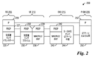
図2は、中継UEをサポートする無線通信システム用の例示的なプロトコルスタックの図200を示す。ダイアグラム200は、RD205、中継UE210、eNB215、およびP−GW220に対するプロトコルスタックを含む。RD205に対するプロトコルスタックは、RD205と中継UE210との間の直接リンク上でPDUを送受信するための処理を制御する短距離リンクトランスポートエンティティ225と、RD205によって送受信されるPDCP PDUの処理を制御するパケットデータコンバージェンスプロトコル(PDCP)エンティティ227と、RD205によって送受信されるIPプロトコルPDUを処理するインターネットプロトコル(IP)エンティティ220とを含む。中継UE210に対するプロトコルスタックは、中継UE210とRD205との間の直接リンク上でPDUを送受信するための処理を制御する短距離リンクプロトコルエンティティ230と、RD205から受信されたまたはそこに送信されたPDCP PDUを処理する第1のPDCPエンティティ232と、eNB215から受信されたまたはそこに送信されたPDCP PDUを処理する第2のPDCPエンティティ234と、eNB215から受信されたまたはそこに送信されたPDUを処理するMAC、RLCおよびPHY層を提供するメディアアクセス制御(MAC)/無線リンク制御(RLC)/物理(PHY)層エンティティ236とを含む。
FIG. 2 shows a diagram 200 of an exemplary protocol stack for a wireless communication system supporting relay UEs. Diagram 200 includes protocol stacks for
eNB215に対するプロトコルスタックは、中継UE210から受信されたまたはそこに送信されたPDUを処理するMAC、RLC、およびPHY層を提供するMAC/RLC/PHY層エンティティ240と、中継UE210から受信されたまたはそこに送信されたPDCP PDUを処理するPDCP層エンティティ242と、S−GWを介してPDUに対して中継サービスを提供するユーザデータ(GTP−U)中継エンティティ244に対する汎用パケット無線サービス(GPRS)トンネリングプロトコル(GTP)とを含む。P−GW220に対するプロトコルスタックは、eNB215から受信されたまたはそこに送信されたPDUを処理するGTP−U中継エンティティ250と、P−GW220によって送受信されるIPプロトコルPDUを処理するIPエンティティ252とを含む。
The protocol stack for the
図2は、プロトコルスタック内の同じレベルのエンティティ間の直接接続を示しているが、PDUはプロトコルスタック内の同じレベルのエンティティ間で直接転送されない。代わりに、PDUは、送信元デバイスと宛先デバイス、および任意の中間デバイスのそれぞれのプロトコルスタックを通過する。例示的な例として、RD205によって受信されたP−GW220からのIP PDUは、IPエンティティ252で開始し、次いでIPエンティティ229に到着する前にGTP−U中継エンティティ250、GTP−Uエンティティ244、PDCPエンティティ242、MAC/RLC/PHY層エンティティ240、MAC/RLC/PHY層エンティティ236、第2のPDCPエンティティ234、第1のPDCPエンティティ232、短距離リンクプロトコルエンティティ230、短距離リンクトランスポートエンティティ225、およびPDCPエンティティ227を通過する。
Although FIG. 2 shows direct connections between same-level entities within the protocol stack, PDUs are not directly transferred between same-level entities within the protocol stack. Instead, the PDU goes through the respective protocol stacks of the source and destination devices, and any intermediate devices. As an illustrative example, an IP PDU from P-
例示的な実施形態によると、RDに関連付けられたPDUは単一のDRB上に集約される。アップリンク上で単一の中継UEによって中継されるRDに関連付けられたPDUは、中継UEとそのサービングeNBとの間の単一のDRB上で集約されて送信される。PDUを単一のDRB上で集約することは、各RDに関連付けられたPDUが個々のDRBを使用して送信される場合よりも、中継UEがより多くのRDをサポートすることを可能にする。したがって、サポートされるRDの数が増え、通信システムの効率が向上する。ダウンリンク上で単一の中継UEによって中継されるRDに関連付けられたPDUは、中継UEにおいて単一のDRBで受信され、個々のPDUに分割されて対応するRDに転送される。 According to an exemplary embodiment, PDUs associated with RDs are aggregated on a single DRB. PDUs associated with RDs relayed by a single relay UE on the uplink are aggregated and transmitted on a single DRB between the relay UE and its serving eNB. Aggregating PDUs on a single DRB allows the relay UE to support more RDs than if the PDUs associated with each RD were sent using individual DRBs. . Therefore, the number of RDs supported is increased and the efficiency of the communication system is improved. The PDUs associated with the RDs relayed by a single relay UE on the downlink are received in a single DRB at the relay UE, split into individual PDUs and transferred to the corresponding RDs.
例示的な実施形態によると、RDに関連付けられたPDCP PDUは、単一のDRB上で集約される。アップリンク上で単一の中継UEによって中継されるRDに関連付けられたPDCP PDUは、中継UEとそのサービングeNBとの間の単一のDRB上で集約されて送信される。ダウンリンク上で単一の中継UEによって中継されるRDに関連付けられたPDCP PDUは、中継UEにおいて単一のDRBで受信され、個々のPDCP PDUに分割されて対応するRDに転送される。 According to an exemplary embodiment, PDCP PDUs associated with RDs are aggregated on a single DRB. PDCP PDUs associated with RDs relayed by a single relay UE on the uplink are aggregated and transmitted on a single DRB between the relay UE and its serving eNB. A PDCP PDU associated with an RD relayed by a single relay UE on the downlink is received in a single DRB at the relay UE, divided into individual PDCP PDUs and transferred to the corresponding RD.
図3は、無線通信システムサポート中継UEのデバイスのPDCPエンティティ間の例示的接続300を示す。アップリンクでは、図3に示すように、PDCPエンティティ304を有する第1のRD(RD1)302およびPDCPエンティティ308を有する第2のRD(RD2)306は、個々のRD−UEリンク310によって中継UE312にPDCPレベルで論理的に接続される。中継UE312は、単一のDRB325によってeNB327に論理的に接続されている。別々のRDからのPDCP PDUは、個々のRD−UEリンク310を介して中継UE312に送信され、そこで第1のPDCPエンティティ315はPDCP PDUを受信し、それらを複数のネスト化されたPDCP PDUを生成して一緒に集約する第2のPDCPエンティティ320に転送する。第2のPDCPエンティティ320は、集約されたPDCP PDUを単一のDRB325を介してeNB327に送信する。PDCPエンティティ330は、集約されたPDCP PDUを処理する。
FIG. 3 shows an
ダウンリンクにおいて、PDCPエンティティ330は、複数のネスト化されたPDCP PDUを含む集約されたPDCP PDUを単一のDRB 325を介して中継UE 312の第2のPDCPエンティティ320に送信する。第2のPDCPエンティティ320は、集約されたPDCP PDUを複数のネスト化されたPDCP PDUに分割し、複数のネスト化されたPDCP PDUを第1のPDCPエンティティ315に転送する。第1のPDCPエンティティ315は、複数のネスト化されたPDCP PDUを個々のRD−UEリンク310を介してそれぞれのRDに送信する。
In the downlink, the
図4は、例示的なPDCP PDU400を示す。PDCP PDU400は、PDCP制御PDUの一例としてロバストヘッダ圧縮(RoHC)フィードバックPDUを示す。PDCP PDU400は、少なくとも第1のオクテット(OCTET1)405および第2のオクテット(OCTET2)407を含む。第1のオクテット405は、データ/制御(D/C)ビット410内のPDUタイプインジケータ、PDUタイプフィールド415内のPDUタイプインジケータ、ビット420およびビット422などの複数の予約ビットなどの制御情報を含む。RoHCフィードバックPDUとして、D/Cビット410は、PDCP PDU400が制御PDUおよびPDUを含むことを示す「1」に設定され、タイプフィールド415は、PDCP PDU400がRoHCフィードバックPDUであることを示す「001」に設定される。第2のオクテット407は、RoHCフィードバックPDU(すなわち、PDCP PDU400)のフィードバック情報を含む。PDUタイプフィールド415が「000」に設定されている場合、PDCP PDU400はステータス報告PDUである。PDUタイプフィールド415の他の値は将来の使用のために予約されている。
FIG. 4 shows an
第1のオクテット(OCTET1)405は、PDUのパケットヘッダがどのように使用されるかと同様の方法で使用され得る。第1のオクテット405に含まれる情報は特定のフォーマットに準拠し、内容はPDCP PDU400が適切に処理されることを確実にするためにPDCP PDU400のフォーマットおよびないようを記述するために使用され得る一方、PDUのパケットヘッダは特定のフォーマットおよびPDUが対象の宛先に確実に到達するのに役立つ内容を有する情報を含む。したがって、PDCP PDUの先頭に含まれる情報、例えば、第1のオクテット405は、技術的にはパケットヘッダではないが、ヘッダと呼ばれることがある。本明細書で使用される場合、用語ヘッダは、PDCP PDUが適切に処理されることを保証するために使用される特定のフォーマットおよび内容を有する情報を識別する一方、用語パケットヘッダは、PDCP PDUが確実に対象の宛先に到着するために使用される情報を識別する。説明はPDCP PDUの第1のオクテットがヘッダと呼ばれることに着目しているが、本明細書に提示される例示的な実施形態は、指定されたフォーマットに準拠する情報や内容を含み、PDCP PDUが正しく処理されることを保証するために使用される、第1のオクテットのサブセット、複数のオクテット、複数のオクテットのサブセットなどの他の情報量で動作可能である。したがって、これらの他の情報量もまたヘッダと呼ばれることがある。
The first octet (OCTET1) 405 may be used in a similar manner as the packet header of the PDU is used. Whereas the information contained in the
例示的な実施形態によれば、例えば、単一のDRB上で一緒に集約されるPDCP PDUに関連付けられたRDの識別を可能にするために新しいPDCP PDUタイプが指定される。異なるRDに対して別々のDRBを使用することで、どのRDがPDCP PDUの送信元あるいは受信者であるかを区別できるようになる。ただし、複数のPDCP PDUが集約されて単一のDRBを介して送信される場合、PDCP PDUの送信元または受信者を簡単に識別することはできない。 According to an exemplary embodiment, a new PDCP PDU type is specified to allow, for example, identification of RDs associated with PDCP PDUs aggregated together on a single DRB. The use of different DRBs for different RDs makes it possible to distinguish which RD is the source or receiver of PDCP PDUs. However, when multiple PDCP PDUs are aggregated and transmitted via a single DRB, it is not possible to easily identify the source or the receiver of the PDCP PDUs.
例示的な実施形態によると、ネスト化されたPDCP PDUは、指定された値に設定されたPDUタイプフィールドを有する既存のPDCP PDUフォーマットを利用する。既存のPDUフォーマットを利用することにより、新しいPDUフォーマットを設計する必要がなくなる。さらに、ネスト化されたPDCP PDUはPDCP PDUの外観を持つが未定義の値に設定されたPDUタイプフィールドを有するため、レガシーデバイスは、ネスト化されたPDCP PDUを処理する方法がわからないが、それでもなおネスト化されたPDCP PDUを検知できる。 According to an exemplary embodiment, the nested PDCP PDU utilizes the existing PDCP PDU format with the PDU Type field set to the specified value. By utilizing the existing PDU format, there is no need to design a new PDU format. Furthermore, because the nested PDCP PDU has the appearance of a PDCP PDU but has a PDU type field set to an undefined value, legacy devices do not know how to handle nested PDCP PDUs, but nevertheless Note that nested PDCP PDUs can be detected.
例示的な実施形態によると、PDCP PDUのPDUタイプフィールドの予約値のうちの1つまたは複数は、ネスト化されたPDCP PDUを示すために使用される。PDUタイプフィールドの第1の値は、ネストされたPDCP PDUが転送用のデータPDUを含むことを示すために使用され得る。PDUタイプフィールドの第2の値は、ネスト化されたPDCP PDUが転送用のデータPDUを含み、その内容はユーザデータではなくシグナリングを含むことを示すために使用され得る。手短に言えば、シグナリングを含む内容を有するデータPDUは、転送のためのシグナリングPDUと呼ばれることがある。PDUタイプフィールドの第1および第2の値は、まだ予約されていない、考え得るPDUタイプフィールド値から選択されてもよい。例示的な例として、値「000」および「001」は既に予約されているので、第1および第2の値は値「010」、「011」、「100」、「101」、「110」、および「111」(すなわち、PDUタイプフィールドの残りの6つの考え得る値)から選択され得る。例えば、第1の値は「010」であり、第2の値は「011」であってもよい。あるいは、PDUタイプフィールドの単一の値は、データがユーザデータ(データPDU)またはシグナリング(シグナリングメッセージ)のいずれを含むかに関係なく、ネスト化されたPDCP PDUが転送用のデータを含むことを示すために使用されてもよい。 According to an exemplary embodiment, one or more of the reserved values in the PDU Type field of PDCP PDUs are used to indicate a nested PDCP PDU. The first value of the PDU Type field may be used to indicate that the nested PDCP PDU contains a data PDU for transfer. The second value of the PDU Type field may be used to indicate that the nested PDCP PDU contains a data PDU for transfer, the content of which contains signaling rather than user data. Briefly, a data PDU with content that includes signaling may be referred to as a signaling PDU for transfer. The first and second values of the PDU type field may be selected from possible PDU type field values that have not yet been reserved. As an illustrative example, the values "000" and "001" are already reserved, so the first and second values are values "010", "011", "100", "101", "110". , And “111” (ie, the remaining six possible values of the PDU type field). For example, the first value may be "010" and the second value may be "011". Alternatively, a single value in the PDU Type field indicates that the nested PDCP PDU contains data for transfer, regardless of whether the data contains user data (data PDU) or signaling (signaling message). It may be used to indicate.
例示的な実施形態によると、第1のネスト化されたPDCP PDUタイプは、転送用のデータPDUを含むことを示し、第2のネスト化されたPDCP PDUタイプは、転送用のシグナリングPDUを含むことを示す。ネスト化されたPDCP PDUが第2のネスト化されたPDCP PDUタイプである状況(例えば、PDUタイプフィールドが第2の値、即ち「011」に等しい)では、中継UEは、たとえRDシグナリングが中継UEのDRB上で搬送されるとしても、ネスト化されたPDCP PDUをDRB上のデータまたはシグナリング無線ベアラ(SRB)上のシグナリングとして送信し得る。正確な挙動は、RD−UEリンクのアクセス技術に依存し得る。例示的な例として、RD−UEリンクがPC5インタフェースを介したLTEサイドリンクトランスポートを使用する場合、ネスト化されたPDCP PDUは、ネスト化されたPDCP PDU内に含まれるPDCP PDUがサイドリンクデータ無線ベアラ(S−DRB)上でまたはサイドリンクシグナリング無線ベアラ(S−SRB)上で送信されるか否かを判断する。他のアクセス技術は、適用される異なる規則を有し得ることに留意されたい。 According to an exemplary embodiment, the first nested PDCP PDU type indicates to include a data PDU for transfer and the second nested PDCP PDU type includes a signaling PDU for transfer. Indicates that. In situations where the nested PDCP PDU is a second nested PDCP PDU type (eg, the PDU type field is equal to a second value, ie, “011”), the relay UE may Nested PDCP PDUs may be sent as data on the DRB or signaling on a signaling radio bearer (SRB), even if carried on the DRB of the UE. The exact behavior may depend on the access technology of the RD-UE link. As an illustrative example, if the RD-UE link uses LTE sidelink transport over a PC5 interface, the nested PDCP PDU is a PDCP PDU contained within the nested PDCP PDU. Determine whether it is transmitted on a radio bearer (S-DRB) or on a sidelink signaling radio bearer (S-SRB). Note that other access technologies may have different rules that apply.
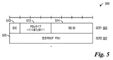
図5は、例示的なネスト化されたPDCP PDU500を示す。第1のオクテット(OCT1)505は、ネスト化されたPDCP PDU500の制御情報を含み得る。ヘッダとして機能する第1のオクテット505は、ネスト化されたPDCP PDU 500がデータPDUであるか制御PDUであるかを示すD/Cビット510と、PDUタイプを示すPDUタイプフィールド512と、ネスト化されたPDCP PDU500に含まれるPDCP PDUに関連付けられたRDの識別子(すなわち、RD ID)を示すRD識別子フィールド514とを含む。D/Cビット510は1ビットフィールドであってもよく、PDUタイプフィールド512は3ビットフィールドであってもよく、RD識別子フィールド514は4ビットフィールドであってもよい。サイズが4ビットであるため、RD識別子フィールド514は、ネスト化されたPDCP PDU500が最大16個のRDをサポートすることを可能にする。しかしながら、より多くのRDのサポートを可能にするためにRD識別子フィールド514はより大きくされてもよく、例えば、RD識別子フィールド514は、必要に応じて第2のオクテット以上に拡張してもよい。第2オクテット(OCT2)507およびネスト化されたPDCP PDU500の後続のオクテットは、必要に応じて完全なPDCP PDU520からなる。言い換えれば、第2のオクテット507およびネスト化されたPDCP PDU500の後続のオクテットは集約されるPDCP PDUを保持するために使用される。
FIG. 5 shows an exemplary nested
図6は、RoHCフィードバックPDUを含む例示的なネスト化されたPDCP PDU600を示す。ネスト化されたPDCP PDU600は、ネスト化されたPDCP PDU600に対するヘッダ615として機能する第1のオクテット(OCT1)605を含む。ネスト化されたPDCP PDU600はまた、RoHCフィードバックPDU620を含む第2のオクテット(OCT2)607および第3のオクテット(OCT3)609(ならびに必要に応じて後続のオクテット)も含む。RoHCフィードバックPDU620は、図4に示されるPDCP PDU400などの完全なPDCP PDUである。
FIG. 6 shows an exemplary nested
ネスト化されたPDCP PDU500およびネスト化されたPDCP PDU600などのネスト化されたPDCP PDUは、PDCP−in−PDCP処理を可能にし、第1のデバイス内の送信側PDCPエンティティは、ダブルヘッダPDU(2つのヘッダを有するPDU)を生成する。第1のヘッダは、ネスト化されたPDCP PDUが集約されて単一のDRBを介して送信される際に、ネスト化されたPDCP PDU内に含まれるPDCP PDUに関連付けられたRDを識別するために使用されてもよく、そのネスト化されたPDCP PDU500が実際にネスト化されたPDCP PDUである。第2のヘッダは、PDCP PDU自体を識別するために使用される。
Nested PDCP PDUs, such as nested
図7は、ダウンリンクにおいて発生する例示的な処理700のフロー図を示す。PDCP PDUが中継UEに到着する(イベント705)。PDCP PDUは、例えば、UMTS地上波無線アクセスネットワーク(UTRAN)と中継UEとの間のユニバーサルモバイルテレコミュニケーションシステム(UMTS)エアインタフェース(または単にUuインタフェース)を介してDRBを介して到着する。PDCP PDUは、PHY層710、MAC層712、RLC層714、およびPDCP層716内のエンティティによって処理される。
FIG. 7 shows a flow diagram of an
PDCP層716における処理は、PDCP PDUがネスト化されたPDCP PDUであるか否かを判定することを含み得る。PDCP PDUがネスト化されたPDCPパケットであるか否かの判断は、PDCP PDUのヘッダ内のPDUタイプフィールドを調べることによって実行され得る。PDCP PDUがネスト化されたPDCP PDUではない場合、PDCP PDUは通常通りに中継UEの上位層に配信される(イベント725)。PDCP PDUがネスト化されたPDCP PDUである場合(PDUタイプフィールドが、例えば、第1の値「010」または第2の値「011」のいずれかに設定されている場合)、PDCP層716のエンティティは第1のヘッダをPDCP PDUから取り除き、RD識別子フィールドで示されるようにRD ID Y 730に関連付けられた短距離リンクなどの短距離リンクを介して、修正されたPDCP PDUを受信者RDに送信し得る。あるいは、PDCP層716のエンティティは、第1のヘッダを取り除かずにPDCP PDUを送信し、第2のヘッダを正しく処理することを受信者に依存し得る。
Processing at
RDにおける処理は、PDUタイプフィールド内の値に基づいて制御プレーン(Cプレーン)またはユーザプレーン(Uプレーン)通信を区別し(イベント735)、修正されたPDCP PDUを、例えば、UプレーンからRD Y 745またはCプレーンからRD X 740へなど、RD−UEリンクのそれぞれのプレーン(PDUタイプフィールドの値が第1の値に設定されている場合はUプレーン、あるいはPDUタイプフィールドの値が第2の値に設定されている場合はCプレーンのいずれか)で転送し得る。
The processing at the RD distinguishes control plane (C plane) or user plane (U plane) communication based on the value in the PDU type field (event 735), and modifies the modified PDCP PDU, eg, from U plane to
図7に示すダウンリンク通信は、RDデータを搬送するためのeNBと中継UEとの間の単一のDRBに対するものである。eNBと中継UEとの間にDRBが複数のある状況が存在する。例えば、サービス品質(QoS)の差別化を実施するために複数のDRBが存在してもよい。DRBが複数ある状況では、同じ処理が各DRBに対して個別に発生する。 The downlink communication shown in FIG. 7 is for a single DRB between an eNB for carrying RD data and a relay UE. There is a situation where there are multiple DRBs between the eNB and the relay UE. For example, there may be multiple DRBs to implement quality of service (QoS) differentiation. In situations where there are multiple DRBs, the same process occurs for each DRB individually.
図8は、アップリンクにおいて発生する例示的な処理800のフロー図を示す。1つまたは複数のPDCP PDUは、例えば、RD X 805のCプレーンまたはRD Y 810のUプレーンなど、さまざまなRD−UEリンクのCプレーンまたはUプレーンを介して到着する。RDにおける処理は、個別のRDベースでCプレーンおよびUプレーンのPDCP PDUをマージし得る(イベント815)。PDCP PDU(CプレーンおよびUプレーンの両方のPDCP PDU)は、RD X 820に対する短距離リンクなど、それぞれのRDに関連付けられた短距離リンクを介して中継UEにおいて受信される。
FIG. 8 shows a flow diagram of an
PDCP PDUは、PHY層825、MAC層827、RLC層829、およびPDCP層831内のエンティティによって処理される。PDCP層831内のエンティティは、他のタイプのPDCP PDU(PDUタイプフィールドを有するPDCPパケットは、例えば、第1の値、「010」、または第2の値、「011」、以外の値に、設定される)も中継UEの下位層から受信し処理し得る(イベント840)。PDCP層831内のエンティティは、RDからのPDCP PDUを、対応するネスト化されたPDCP PDUに含まれる各PDCP PDUのソースRDに対応するように調整されたネスト化されたPDCP PDUのヘッダを用いて、ネスト化されたPDCP PDUに配置する。ネスト化されたPDCP PDUは集約され、DRBを介してeNBに送信される(イベント845)。同じDRBのプロトコルエンティティに関連付けられているがRDから受信されていない任意のPDCP PDUもeNBに送信される。
PDCP PDUs are processed by entities within the
図9は、RDとのダウンリンク通信に関与するeNBにおいて発生する例示的な動作900のフロー図を示す。動作900は、eNBがRDとのダウンリンク通信に関与する際にeNBにおいて発生する動作を示し得る。eNBは、送信デバイスとして動作している。
FIG. 9 shows a flow diagram of
動作900は、eNBがRDに関するデータを受信することから開始する(ブロック905)。eNBは、データからPDCP PDUを生成する(ブロック910)。PDCP PDUは、それぞれのRDを中継している中継UEに関連付けられているeNBでPDCPエンティティに配信される(ブロック915)。PDCPエンティティは、PDCP PDUからネスト化されたPDCP PDUを生成する(ブロック920)。ネスト化されたPDCP PDUのヘッダは、ネスト化されたPDCP PDUのRD受信者のRD識別子を含む。eNBは、ネスト化されたPDCP PDUをそれぞれの中継UEに送信する(ブロック925)。ネスト化されたPDCP PDUの送信は、各eNB−中継UEペアが単一のDRBによってサービスを提供されるようにネスト化されたPDCP PDUを集約することを含む。
図10は、RDとのダウンリンク通信に関与する中継UEにおいて発生する例示的な動作1000のフロー図を示す。動作1000は、中継UEがRDとのダウンリンク通信に関与する際に中継UEにおいて発生する動作を示し得る。中継UEは、受信デバイスとして動作している。
FIG. 10 shows a flow diagram of
動作1000は、中継UEがネスト化されたPDCP PDUを受信することから開始する(ブロック1005)。中継UEは、ネスト化された各PDCP PDUに関連付けられたRDを識別する(ブロック1010)。中継UEは、ネスト化されたPDCP PDUからPDCP PDUを生成する(ブロック1015)。一例として、中継UEは、ネスト化されたヘッダをネスト化されたPDCP PDUから取り除いてPDCP PDUを生成する。中継UEは、PDCP PDUをそれぞれのRDに送信する(ブロック1020)。PDCP PDUは、短距離リンクを介してそれぞれのRDに送信される。代替として、中継UEは、ネスト化されたPDCP PDUからPDCP PDUを生成せずに、ネスト化されたPDCP PDUを修正なしにそれぞれのRDに送信しない。
図11は、RDとのアップリンク通信に関与する中継UEにおいて発生する例示的な動作1100のフロー図を示す。動作1100は、中継UEがRDとのアップリンク通信に関与する際に中継UEにおいて発生する動作を示し得る。中継UEは、送信デバイスとして動作している。
FIG. 11 shows a flow diagram of
動作1100は、中継UEがRDからPDCP PDUを受信することから開始する(ブロック1105)。PDCP PDUは、短距離リンクを解して受信される。中継UEは、中継UEにサービスを提供するeNBに関連付けられたPDCPエンティティにPDCP PDUを配信する(ブロック1110)。中継UEのPDCPエンティティは、PDCP PDUからネスト化されたPDCP PDUを生成する(ブロック1115)。ネスト化されたPDCP PDUのヘッダは、PDCP PDUに関連付けられたRDの識別子を含む。中継UEは、ネスト化されたPDCP PDUをeNBに送信する(ブロック1120)。ネスト化されたPDCP PDUの送信は、中継UE−eNBペアが単一のDRBによってサービスが提供されるようにネスト化されたPDCP PDUを集約することを含む。
図12は、RDとのアップリンク通信に関与するeNBにおいて発生する例示的な動作1200のフロー図を示す。動作1200は、eNBがRDとのアップリンク通信に関与する際にeNBにおいて発生する動作を示し得る。eNBは、受信デバイスとして動作している。
FIG. 12 shows a flow diagram of
動作1200は、ネスト化されたPDCP PDUを受信するeNBから開始する(ブロック1205)。eNBは、ネスト化された各PDCP PDUに関連付けられたRDを識別する(ブロック1210)。eNBは、ネスト化されたPDCP PDUからPDCP PDUを生成する(ブロック1215)。一例として、eNBは、ネスト化されたドヘッダをネスト化されたPDCP PDUから取り除き、PDCP PDUを生成する。eNBは、PDCP PDUをそれぞれの受信者に送信する(ブロック1220)。あるいは、eNBは、ネスト化されたPDCP PDUからPDCP PDUを生成せずに、ネスト化されたPDCP PDUを修正なしにそれぞれの受信者に送信しない。
図13は、デバイスがRDとのダウンリンク通信を実行する際に、デバイス間で交換されるメッセージと、デバイスによって実行される動作とを強調するメッセージフロー図1300を示す。メッセージフロー図1300は、S−GW1305、eNB1307、中継UE1309、およびRD1311により交換されるメッセージと、実行される動作とを表示する。
FIG. 13 shows a message flow diagram 1300 highlighting the messages exchanged between devices and the actions performed by the devices as they perform downlink communications with the RD. Message flow diagram 1300 displays the messages exchanged by S-
eNB1307は、RD1311向けのデータを受信する(イベント1315)。データは、RD1311に関連付けられているPDCPエンティティに配信される(イベント1317)。eNB1307は、データから1つまたは複数のPDCP PDUを生成する(イベント1319)。PDCP PDUは、前述のようにフォーマット1321に準拠する。eNB1307は、PDCP PDUを中継UE1309に関連付けられたPDCPエンティティに配信する(イベント1323)。eNB1307は、PDCP PDUからネスト化されたPDCP PDUを生成する(イベント1325)。各PDCP PDUは、結果としてネスト化されたPDCP PDUになる。ネスト化されたPDCP PDUはフォーマット1327にしたがう。例示的な例として、eNB1607がID X(ここで、Xは中継UE1309に対するDRB内でRD 1311を一意に識別する4ビットの識別子である)を有するRD1311に対してネスト化されたPDCP PDUを生成している状況では、eNB1307は、RD1311に関連付けられたPDCPエンティティを使用してPDCP PDUを処理し得る。eNB1307は、例えば、ユーザデータに対してオクテット「1010+X(ここで、「1010」はD/Cビットの「1」およびPDUタイプフィールドの「010」を含む)、シグナリングに対して「1011」+X(ここで、「1011」はD/Cビットの「1」およびPDUタイプフィールドの「011」を含む)を追加し得る。eNB1307は、送信のためにネスト化されたPDCP PDUを下位層に送信し得る。ネスト化されたPDCP PDUが複数ある状況では、ネスト化されたPDCP PDUは、それらが単一のDRBで中継UE1309に送信されることができるように集約される(イベント1329)。
The
中継UE1309は、各ネスト化されたPDCP PDUに関連付けられたRDを識別する(イベント1331)。中継UE1309は、ネスト化されたPDCP PDUに含まれる各PDCP PDUのPDUタイプを識別する(イベント1333)。PDCP PDUのPDUタイプは、PDCP PDU内のPDUタイプフィールドに示される。実装に応じて、中継UE1309は、ネスト化されたPDCP PDUの外側ヘッダ(ネスト化されたPDCP PDUのヘッダ)を取り除く(イベント1335)。中継UE1309がネスト化されたPDCP PDUの先頭オクテットを除去することによってネスト化されたPDCP PDUの外側ヘッダを除去する状況では、結果として得られるPDCP PDUはフォーマット1337に準拠する。中継UE1309は、PDCP PDU(または例示的な実施形態では、中継UE1309が外側ヘッダを除去しないネスト化されたPDCP PDU)をそれぞれのRDに対して送信する(イベント1339)。PDCP PDU(またはネスト化されたPDCP PDU)は、中継UE1309とRD1311との間の短距離リンク上で送信される。一例として、ID Xはまた、PDCP PDUをそれぞれのRDに対して送信するために、使用されて適切な下位エンティティを識別してもよいが、詳細は短距離リンクで使用される無線アクセス技術に依存する。
アップリンクでは、処理は、中継UEおよびeNBで発生する処理と同様であり、これらの処理はダウンリンク処理と同様であるが、ネスト化されたPDCP PDUの送信を実行する中継UEとネスト化されたPDCP PDUを受信するeNBとでは逆になる。中継UEでは、ID Xを有するRDを対象とするPDCP PDUが到着すると、中継UEは、PDCP PDUを中継UEの対応するDRBに関連付けられたPDCPエンティティに配信する。中継UEは、ユーザデータに対してオクテット「1010」+X(ここで、「1010」はD/Cビットの「1」およびPDUタイプフィールドの「010」を含む)またはシグナリングに対してオクテット「1011」+X(ここで、「1011」はD/Cビットの「1」およびPDUタイプフィールドの「011」を含む)を追加し得る。中継UEは、送信のためにネスト化されたPDCP PDUを下位層に送信する。eNBでは、ID Xを有するRDに対するネスト化されたPDCP PDUが中継UEを有するDRBを介して受信されると、eNBは、RDのIDを判定する。実装に応じて、eNBは、ネスト化されたPDCP PDUのヘッダ(すなわち、先頭のオクテット)を削除するかまたは削除しない。PDCP PDUは、RDに関連付けられているPDCPエンティティに配信される。eNB(すなわち、PDCPエンティティ)は、PDCP PDUをDRBの対応するS1ベアラに渡す。RDを明確にするために識別子がS1u上で使用され得ることに留意されたい。 On the uplink, the process is similar to that occurring at the relay UE and eNB, these processes are similar to the downlink process, but nested with the relay UE performing the transmission of the nested PDCP PDUs. The opposite is true for an eNB that receives a PDCP PDU. At the relay UE, when the PDCP PDU for the RD with ID X arrives, the relay UE delivers the PDCP PDU to the PDCP entity associated with the corresponding DRB of the relay UE. The relay UE may octet “1010” + X for user data (where “1010” includes “1” of D / C bit and “010” of PDU type field) or octet “1011” for signaling. + X (where “1011” includes D / C bit “1” and PDU type field “011”) may be added. The relay UE sends the nested PDCP PDUs to lower layers for transmission. At the eNB, when the nested PDCP PDU for the RD with ID X is received via the DRB with the relay UE, the eNB determines the RD's ID. Depending on the implementation, the eNB removes or does not remove the header (ie the first octet) of the nested PDCP PDU. The PDCP PDU is delivered to the PDCP entity associated with the RD. The eNB (ie PDCP entity) passes the PDCP PDU to the corresponding S1 bearer of the DRB. Note that the identifier may be used on S1u to clarify the RD.
例示的な実施形態によれば、RDへの、またはRDからの制御プレーントラフィックを処理するためのシステムおよび方法が提供される。上記で提示された議論は、主にRDへのまたはそこからのユーザプレーントラフィックに焦点を合わせている。ただし、制御プレーントラフィックがRDに送受信される状況がある。制御プレーントラフィックの例には、無線リソース制御(RRC)トラフィック、非アクセス層(NAS)トラフィックなどが含まれる。制御プレーントラフィックは、eNBで生成されるか、またはeNBによって受信され、eNBでカプセル化され得る。しかしながら、eNBは、制御プレーントラフィックを、eNBと中継UEとの間のSRBではなく、DRBで中継UEに送信する。例示的な例として、第2の値(例えば、「011」)に設定されたPDUタイプフィールドを有するネスト化されたPDCP PDUが使用されて制御プレーントラフィックを中継する。 According to an exemplary embodiment, a system and method for handling control plane traffic to and from an RD is provided. The discussion presented above focuses primarily on user plane traffic to and from the RD. However, there are situations where control plane traffic is sent to and received from the RD. Examples of control plane traffic include radio resource control (RRC) traffic, non-access stratum (NAS) traffic, and the like. Control plane traffic may be generated at the eNB or received by the eNB and encapsulated at the eNB. However, the eNB sends the control plane traffic to the relay UE in the DRB instead of the SRB between the eNB and the relay UE. As an illustrative example, a nested PDCP PDU with a PDU type field set to a second value (eg, "011") is used to relay control plane traffic.
図14は、制御プレーントラフィックを中継するために使用される例示的なネスト化されたPDCP PDU1400を示す。ネスト化されたPDCP PDU1400は、ヘッダとして機能する第1のオクテット(OCT1)1405を含む。第1のオクテット1405は、ネスト化されたPDCP PDU1400が転送用のデータPDUまたは転送用の制御PDUを含むか否かを示すD/Cビット1415、PDUタイプを示すPDUタイプフィールド1420、およびネスト化されたPDCP PDU1400に含まれるPDCP PDUと関連付けられたRDの識別子(すなわちRD ID)を示すRD識別子フィールド1425を含む。D/Cビット1415は1ビットフィールドとしてもよく、PDUタイプフィールド1420は3ビットフィールドとしてもよく、RD識別子フィールド1425は4ビットのフィールドとしてもよい。PDUタイプフィールド1420は、ネスト化されたPDCP PDU1400が制御プレーントラフィックを中継するために使用されることを示すために、第2の値、例えば「011」に設定される。言い換えれば、ネスト化されたPDCP PDU1400はシグナリングメッセージを含む。第2のオクテット(OCT2)1407、第3のオクテット(OCT3)1409、および後続のオクテットは、参照により本明細書に組み込まれている3GPP Technology Standard TS 36.323のFigure 6.2.2.1に規定されているSRBに対するPDCP Data PDUフォーマットに準拠し得る。
FIG. 14 shows an exemplary nested
RDに対するRRCまたはNASシグナリングは、SRB1またはSRB2のいずれかで送信され得る。どのSRBがRRCまたはNASシグナリングを送信するために使用されたかの区別を保存することは、中継UEにとって重要であり得、中継UEは、中継UEとRDとの間の短距離リンクの技術的仕様に従って情報を利用し得る。一例として、短距離リンクが複数のSRBを有していない状況であっても、SRB情報をRDに提供し得る。SRB情報はアップリンクにおいても有益であり得る。一例として、たとえ短距離リンクが複数のSRBを有さないとしても、RDは、特定のSRB上で制御プレーントラフィックを送信するように中継UEに通知するようにSRB情報を設定するし得る。 RRC or NAS signaling for RD may be sent on either SRB1 or SRB2. Preserving the distinction of which SRB was used to send RRC or NAS signaling may be important for the relay UE, which may comply with the technical specifications of the short range link between the relay UE and the RD. Information is available. As an example, the SRB information may be provided to the RD even in situations where the short range link does not have multiple SRBs. SRB information may also be useful in the uplink. As an example, the RD may set the SRB information to notify the relay UE to send control plane traffic on a particular SRB, even if the short-range link does not have multiple SRBs.
図15は、どのSRBが制御プレーントラフィックを伝達するのに使用されたかの区別を保持しながら、制御プレーントラフィックを中継するのに使用される例示的なネスト化されたPDCP PDU1500を示す図である。ネスト化されたPDCP PDU1500は、ヘッダとして機能する第1オクテット(OCT1)1505を含み、ネスト化されたPDCP PDU1400の第1オクテット1405と同じである。第2オクテット(OCT2)1507は、制御プレーントラフィックを伝達するためにSRB1またはSRB2が使用されたか否かを示すSRBビット1515を含む。例示的な例として、SRBビット1515が「0」に設定されている場合はSRB1が使用されたことになり、またはSRBビット1515が「1」に設定されている場合はSRB2が使用されたことになる。あるいは、第3のオクテット(OCT3)1509内のビットまたは任意の後続のオクテットがSRBビットとして使用され得る。
FIG. 15 is a diagram illustrating an exemplary nested
図16は、デバイスがRDとのダウンリンクシグナリングを実行すると、デバイス間で交換されるメッセージと、デバイスによって実行される動作とを強調するメッセージフロー図1600を示す。メッセージフロー図1600は、eNB1605、中継UE1607、およびRD1609により交換されるメッセージと、実行される動作とを表示する。
FIG. 16 shows a message flow diagram 1600 highlighting the messages exchanged between devices and the actions performed by the devices as the devices perform downlink signaling with the RD. Message flow diagram 1600 displays the messages exchanged by the
eNB1605は、RD1609に対する制御プレーントラフィック(シグナリング)を生成する(イベント1615)。制御プレーントラフィックは、RD1609に関連付けられたPDCPエンティティに配信される。eNB1605は、制御プレーントラフィックから1つまたは複数のPDCP PDUを生成する(イベント1617)。PDCP PDUはフォーマット1619に準拠する。eNB1605は、PDCP PDUを中継UE1607に関連付けられたPDCPエンティティに配信する(イベント1621)。eNB1605は、PDCP PDUからネスト化されたPDCP PDUを生成する(イベント1623)。各PDCP PDUは、結果としてネスト化されたPDCP PDUになる。ネスト化されたPDCP PDUは、フォーマット1625に準拠する。複数のネスト化されたPDCP PDUがある状況では、ネスト化されたPDCP PDUは、それらが単一のDRB上で中継UE1607に送信されることができるように集約される(イベント1627)。
The
中継UE1607は、ネスト化された各PDCP PDUに関連付けられたRDを識別する(イベント1629)。中継UE1607は、ネスト化されたPDCP PDUに含まれる各PDCP PDUのPDUタイプを識別する(イベント1631)。PDCP PDUのPDUタイプは、図16では転送用のシグナリングPDUとしてであるが、PDCP PDUのヘッダ内のPDUタイプフィールド内に示される。実装によっては、中継UE1607は、ネスト化されたPDCP PDUの外側ヘッダ(ネスト化されたPDCP PDUのヘッダ)を除去し得る(イベント1633)。中継UE1607がネスト化されたPDCP PDUのそれぞれの先頭オクテットを除去することによってネスト化されたPDCP PDUの外側ヘッダを除去するときの状況において、結果として得られるPDCP PDUはフォーマット1635に準拠する。中継UE1607は、PDCP PDU(または中継UE1607が外側ヘッダを除去しない例示的な実施形態においてはネスト化されたPDCP PDU)をそれぞれのRDに送信する(イベント1637)。 PDCP PDU(またはネスト化されたPDCP PDU)は、中継UE1607とRD1609との間の短距離リンク上で送信される。
The
例示的実施形態によれば、RDに関連付けられた制御プレーントラフィックは、DRBではなく中継UEのSRB上で送信される。SRBで制御プレーントラフィックを送信すると、PDUタイプフィールドに2つの予約値を使用する必要がなくなる。さらに、SRBを使用することは、データに対する制御プレーントラフィックのシグナリングの典型的な優先順位付けに対してより互換性があり得る。 According to an exemplary embodiment, the control plane traffic associated with the RD is sent on the SRB of the relay UE rather than the DRB. Sending control plane traffic on the SRB eliminates the need to use two reserved values for the PDU type field. Moreover, using SRB may be more compatible with typical prioritization of signaling of control plane traffic for data.
図17は、SRB上で制御プレーントラフィックを中継するために使用される例示的なネスト化されたPDCP PDU1700を示す。ネスト化されたPDCP PDU1700は、2つのオクテット、第1のオクテット(OCT1)1707および第2のオクテット(OCT2)1709を含む外側ヘッダ1705と、2つ以上のオクテット、第3のオクテット(OCT3)1712および第4のオクテット(OCT4)1714とならびに必要に応じて後続のオクテットを含むPDCP PDU1710とを含む。外側ヘッダ1705は、UE(U)/転送(F)(U/F)ビットフィールド1717を含み、このフィールドは、ネスト化されたPDCP PDU1700がUEシグナリングに使用されるか(例えば、U/Fビットフィールド1717は「0」に設定)または制御プレーントラフィック転送に使用される(例えば、U/Fフィールド1717は「1」に設定)かを示すために使用される。外側ヘッダ1705はまた、ネスト化されたPDCP PDU1700がUEシグナリングに使用されているときのPDCPシーケンス番号(SN)1719と、ネスト化されたPDCP PDU1700に関連付けられたRDのIDを含むRD識別子フィールド1721とを含む。PDCP PDU1710はまた、PDCP PDU1710がUE(この場合はRD)シグナリングまたは制御プレーントラフィック転送用のものであるか否かを示すためにU/Fビットフィールド1723も含む。ほとんどの場合、U/Fビットフィールド1723は、PDCP PDU1710がUEシグナリング用であることを示すように設定される。PDCP PDU1710はまた、RDに対するPDCP SN1725を含む。
FIG. 17 shows an exemplary nested
例示的な実施形態によれば、制御プレーントラフィックは、SRB1またはSRB2のいずれかで送信されてもよく、したがって、どのSRBが制御プレーントラフィックを送信するために使用されたかの区別は、2値インジケータを使用して維持される。eNBと中継UEとの間のトラフィックは所望に応じてSRB1またはSRB2のいずれかを使用することができるので、帯域内指示は不要である。しかしながら、RDに対するSRB情報を保存するために、またはどのSRBを使用するべきかをRDが指定可能にするために、前述のものと同様のSRBインジケータが使用される。 According to an exemplary embodiment, control plane traffic may be sent on either SRB1 or SRB2, and thus the distinction of which SRB was used to send control plane traffic is indicated by a binary indicator. Maintained to use. Intra-band indication is not required as traffic between the eNB and the relay UE can use either SRB1 or SRB2 as desired. However, to store the SRB information for the RD, or to allow the RD to specify which SRB to use, an SRB indicator similar to that described above is used.
図18は、SRB情報を保持しながら、制御プレーントラフィックを中継するのに使用される例示的なネスト化されたPDCP PDU1800を示す図である。ネスト化されたPDCP PDU1800は、2つのオクテット、第1のオクテット(OCT1)1807と第2のオクテット(OCT2)1809とを含む外側ヘッダ1805、および2つ以上のオクテット、第3のオクテット(OCT3)1812および第4のオクテット(OCT4)とならびに必要に応じて後続のオクテットを含むPDCP PDU1810を含む。外側ヘッダ1805は、ネスト化されたPDCP PDU1800がUEシグナリングまたは制御プレーントラフィック転送用に使用されるか否かを示すためにU/Fビットフィールド1817を含む。また、外側ヘッダ1805に含まれるのは、SRB1またはSRB2が制御プレーントラフィックを伝達するために使用されたか否かを示すSRBビット1819である。例示的な例として、SRBビット1819が「0」に設定されている場合はSRB1が使用され、またはSRBビット1819が「1」に設定されている場合はSRB2が使用されたことになる。PDCP PDU1810はまた、PDCP PDU1810がUE(この場合はRD)シグナリングまたは制御プレーントラフィック転送に対するものであるか否かを示すためにU/Fビットフィールド1823を含む。ほとんどの状況では、U/Fビットフィールド1823は、PDCP PDU1810がUEシグナリング用であることを示すように設定される。PDCP PDU1810はまた、SRB情報を保存または指定するためのSRBビット1825を含む。
FIG. 18 is a diagram illustrating an exemplary nested
デバイスがダウンリンクSRB上でネスト化されたPDCP PDUを受信するとき、外側ヘッダのU/Fフィールドがネスト化されたPDCP PDUが制御プレーントラフィック転送に使用されることを示す場合、外側ヘッダのSRBビットおよびネスト化されたPDCP PDUに含まれるPDCP PDUのヘッダのSRBビットは同じ値を持つであろう。デバイスは、2つのSRBビットをチェックすることによりこれを確認し得る、ネスト化されたPDCP PDUのSRBビットを設定し得る、またはこれが真実であると仮定し得る。PDCP PDUがUEシグナリングに使用されることを外側ヘッダのU/Fフィールドが示す場合、かつデバイスが中継UEに接続されていない場合、デバイスはSRBビットを無視し得る。しかし、PDCP PDUがUEシグナリングに使用されていることを外側ヘッダのU/Fフィールドが示し、かつデバイスが中継UEに接続されている場合、SRBビットはネスト化されたPDCP PDUがSRB1またはSRB2上で受信されると見なすか否かを示す。 When a device receives a nested PDCP PDU on a downlink SRB, if the U / F field of the outer header indicates that the nested PDCP PDU is used for control plane traffic forwarding, then the outer header SRB The bits and the SRB bit of the PDCP PDU header contained in the nested PDCP PDU will have the same value. The device may confirm this by checking two SRB bits, set the SRB bit in the nested PDCP PDU, or assume that this is true. The device may ignore the SRB bit if the U / F field of the outer header indicates that the PDCP PDU is used for UE signaling and if the device is not connected to the relay UE. However, if the U / F field of the outer header indicates that the PDCP PDU is used for UE signaling, and the device is connected to the relay UE, the SRB bit indicates that the nested PDCP PDU is on SRB1 or SRB2. Indicates whether or not it is considered to be received by.
デバイスがアップリンクSRB上でネスト化されたPDCP PDUを送信するとき、そのデバイスがRDに対する制御プレーントラフィックを転送している(すなわち、そのデバイスが中継UEである)場合、そのデバイスは外側ヘッダのSRBビットをネスト化されたPDCP PDUに含まれるPDCP PDUのヘッダのSRBビットと等しく設定する。デバイスが中継UEに接続されたRDである場合、デバイスはどのSRBにPDCP PDUが送信されるべきかを示すようにSRBビットを設定する。そうでない場合、SRBビットは予約ビットと見なされ、特定の値、例えば「0」に設定し得る。 When a device sends a nested PDCP PDU on the uplink SRB, if the device is forwarding control plane traffic for the RD (ie, the device is a relay UE), the device will send the outer header Set the SRB bit equal to the SRB bit in the header of the PDCP PDU contained in the nested PDCP PDU. If the device is an RD connected to a relay UE, the device sets the SRB bit to indicate which SRB the PDCP PDU should be sent to. Otherwise, the SRB bit is considered a reserved bit and may be set to a particular value, eg "0".
図19は、デバイスがSRBを用いてRDとのダウンリンクシグナリングを実行すると、デバイス間で交換されるメッセージと、デバイスによって実行される動作とを強調するメッセージフロー図1900を示す。メッセージフロー図1900は、eNB1905、中継UE1907、およびRD1909により交換されるメッセージと、実行される動作とを表示する。
FIG. 19 shows a message flow diagram 1900 highlighting the messages exchanged between devices and the actions performed by the devices when the devices perform downlink signaling with RD using SRB. Message flow diagram 1900 displays the messages exchanged by the
eNB1905は、RD1909に対する制御プレーントラフィック(シグナリング)を生成する(イベント1915)。制御プレーントラフィックは、RD1909に関連付けられたPDCPエンティティに配信される。eNB1905は、制御プレーントラフィックから1つまたは複数のPDCP PDUを生成する(イベント1917)。PDCP PDUはフォーマット1919に準拠する。eNB1905は、PDCP PDUを中継UE1907に関連付けられたPDCPエンティティに配信する(イベント1921)。eNB1905は、PDCP PDUからネスト化されたPDCP PDUを生成する(イベント1923)。各PDCP PDUは結果として、ネスト化されたPDCP PDUになる。ネスト化されたPDCP PDUはフォーマット1925に準拠する。ネスト化されたPDCP PDUが複数ある状況では、ネスト化されたPDCP PDUは、それらが単一のDRB上で中継UE1907に送信されることができるように集約される(イベント1927)。
The
中継UE1907は、ネスト化された各PDCP PDUに関連付けられたRDを識別する(イベント1929)。実装に応じて、中継UE1907は、ネスト化されたPDCP PDUの外側ヘッダ(ネスト化されたPDCP PDUのヘッダ)を除去し得る(イベント1931)。中継UE1907がネスト化されたPDCP PDUの先頭オクテットを除去することによってネスト化されたPDCP PDUの外側ヘッダを除去する状況では、結果として得られるPDCP PDUはフォーマット1933に準拠する。中継UE1907は、PDCP PDU(または中継UE1907が外側ヘッダを除去しない例示的な実施形態ではネスト化されたPDCP PDU)をそれぞれのRDに送信する(イベント1935)。PDCP PDU(またはネスト化されたPDCP PDU)は、中継UE1907とRD1909との間の短距離リンク上で送信される。
The
図20は、本明細書で説明される方法を実行するための実施形態の処理システム2000であり、ホストデバイスにインストールされ得る処理システム2000のブロック図を示す。図示されるように、処理システム2000は、プロセッサ2004、メモリ2006、およびインタフェース2010から2014を含み、これらは図20に示されるように配置されても(またはされなくても)よい。プロセッサ2004は、計算および/または他の処理関連タスクを実行するように適合された任意のコンポーネントまたはコンポーネントの集合であってもよく、メモリ2006は、プロセッサ2004による実行対象のプログラミングおよび/または命令を格納するように適合された任意のコンポーネントまたはコンポーネントの集合であってもよい。実施形態において、メモリ2006は、非一過性のコンピュータ可読媒体を含む。インタフェース2010、2012、2014は、処理システム2000が他のデバイス/コンポーネントおよび/またはユーザと通信することを可能にする任意のコンポーネントまたはコンポーネントの集合であってもよい。例えば、インタフェース2010、2012、2014のうちの1つまたは複数は、プロセッサ2004からのデータ、制御、または管理メッセージをホストデバイスおよび/またはリモートデバイスにインストールされたアプリケーションに通信するように適合され得る。別の例として、インタフェース2010、2012、2014のうちの1つまたは複数は、ユーザまたはユーザデバイス(例えば、パーソナルコンピュータ(PC)など)が処理システム2000とインタラクト/通信することを可能にするように適合され得る。処理システム2000は、長期記憶装置(例えば、不揮発性メモリなど)などの、図20には示されていない追加コンポーネントを含んでもよい。
FIG. 20 is a block diagram of an
いくつかの実施形態では、処理システム2000は、電気通信ネットワークにアクセスしている、またはそうでなければその一部であるネットワークデバイスに含まれる。一例では、処理システム2000は、基地局、中継局、スケジューラ、コントローラ、ゲートウェイ、ルータ、アプリケーションサーバ、アプリケーションサーバ、または電気通信ネットワーク内の他の任意のデバイスなどの無線または有線の電気通信ネットワーク内のネットワーク側デバイスに位置する。他の実施形態では、処理システム2000は、移動局、ユーザ装置(UE)、パーソナルコンピュータ(PC)、タブレット、ウェアラブル通信デバイス(例えば、スマートウォッチなど)、または電気通信ネットワークにアクセスするように適合された他の任意のデバイスなどの無線または有線の電気通信ネットワークにアクセスするユーザ側デバイス内に位置する。
In some embodiments,
いくつかの実施形態では、インタフェース2010、2012、2014のうちの1つまたは複数は、電気通信システムを介してシグナリングを送受信するように適合されたトランシーバに処理システム2000を接続する。図21は、電気通信ネットワークを介してシグナリングを送受信するように適合されたトランシーバ2100のブロック図を示す。トランシーバ2100は、ホストデバイスにインストールされ得る。図示されるように、トランシーバ2100は、ネットワーク側インタフェース2102、カプラ2104、送信機2106、受信機2108、信号プロセッサ2110、およびデバイス側インタフェース2112を備える。ネットワーク側インタフェース2102は、無線または有線の電気通信ネットワークを介してシグナリングを送信または受信するように構成された任意のコンポーネントまたはコンポーネントの集合を含み得る。カプラ2104は、ネットワーク側インタフェース2102を介した双方向通信を容易にするように適合された任意のコンポーネントまたはコンポーネントの集合を含み得る。送信機2106は、ベースバンド信号をネットワーク側インタフェース2102を介する送信に適する変調搬送波信号に変換するように適合された任意のコンポーネントまたはコンポーネントの集合(たとえば、アップコンバータ、電力増幅器など)を含み得る。受信機2108は、ネットワーク側インタフェース2102を介して受信された搬送波信号をベースバンド信号に変換するように適合された任意のコンポーネントまたはコンポーネントの集合(たとえば、ダウンコンバータ、低雑音増幅器など)を含み得る。信号プロセッサ2110は、ベースバンド信号をデバイス側インタフェース2112を介した通信に適したデータ信号に変換するように、またはその逆の変換を行うように適合された任意のコンポーネントまたはコンポーネントの集まりを含み得る。デバイス側インタフェース2112は、信号プロセッサ2110とホストデバイス(例えば、処理システム2000、ローカルエリアネットワーク(LAN)ポートなど)内のコンポーネントとの間でデータ信号を通信するように適合された任意のコンポーネントまたはコンポーネントの集合を含み得る。
In some embodiments, one or more of
トランシーバ2100は、任意の種類の通信媒体を介してシグナリングを送受信し得る。いくつかの実施形態では、トランシーバ2100は無線媒体を介してシグナリングを送受信する。例えば、トランシーバ2100は、セルラプロトコル(たとえば、ロングタームエボリューション(LTE)など)、ワイヤレスローカルエリアネットワーク(WLAN)プロトコル(例えば、Wi−Fiなど)、または任意の他の種類の無線プロトコル(例えば、Bluetooth、近距離無線通信(NFC)など)などの無線電気通信プロトコルに従って通信するように適合された無線トランシーバであり得る。そのような実施形態では、ネットワーク側インタフェース2102は、1つまたは複数のアンテナ/放射エレメントを備える。例えば、ネットワーク側インタフェース2102は、単一アンテナ、複数の別々のアンテナ、または多層通信用に構成されたマルチアンテナアレイ、例えば、単一入力複数出力(SIMO)、複数入力単一出力(MISO)、複数入力複数出力(MIMO)などを含み得る。他の実施形態では、トランシーバ2100は、有線媒体、例えば、ツイストペアケーブル、同軸ケーブル、光ファイバなどを介してシグナリングを送受信する。特定の処理システムおよび/またはトランシーバは、表示されているすべてのコンポーネント、またはコンポーネントのサブセットのみを利用してもよく、統合化のレベルはデバイス毎に異なってもよい。
本明細書で提供される実施形態の方法の1つまたは複数のステップは、対応するユニットまたはモジュールによって実行され得ることを理解されたい。例えば、信号は、送信ユニットまたは送信モジュールによって送信されてもよい。信号は、受信ユニットまたは受信モジュールによって受信されてもよい。信号は、処理ユニットまたは処理モジュールによって処理されてもよい。他のステップは、生成ユニット/モジュール、および/または集約ユニット/モジュールによって実行され得る。それぞれのユニット/モジュールは、ハードウェア、ソフトウェア、またはそれらの組み合わせであり得る。例えば、1つまたは複数のユニット/モジュールは、フィールドプログラマブルゲートアレイ(FPGA)または特定用途向け集積回路(ASIC)などの集積回路としてもよい。 It should be appreciated that one or more steps of the method of the embodiments provided herein may be performed by a corresponding unit or module. For example, the signal may be transmitted by a transmitter unit or module. The signal may be received by a receiving unit or a receiving module. The signal may be processed by a processing unit or processing module. Other steps may be performed by the generation unit / module and / or the aggregation unit / module. Each unit / module can be hardware, software, or a combination thereof. For example, one or more units / modules may be an integrated circuit such as a field programmable gate array (FPGA) or application specific integrated circuit (ASIC).
本開示およびその利点を詳細に説明してきたが、添付の特許請求の範囲によって規定される本開示の精神および範囲から逸脱することなく、本明細書では様々な変形、置換、および変更を行うことができることを理解されたい。 While the present disclosure and its advantages have been described in detail, various changes, substitutions, and alterations may be made herein without departing from the spirit and scope of the disclosure as defined by the appended claims. Please understand that
Claims (20)
前記送信デバイスによって、第1の遠隔デバイス(RD)に関連付けられた第1のパケットデータコンバージェンスプロトコル(PDCP)プロトコルデータユニット(PDU)を受信するステップであって、前記第1のPDCP PDUは少なくとも第1のPDCPヘッダを含む、ステップと、
前記送信デバイスによって、前記第1のPDCP PDUに従って第1のネスト化されたPDCP PDUを生成するステップであって、前記第1のネスト化されたPDCP PDUは、第2のPDCPヘッダと前記第1のPDCP PDUとを含み、前記第2のPDCPヘッダは、前記第1のネスト化されたPDCP PDUが第1の中継されたPDCP PDUを含むことを示す第1のPDUタイプインジケータと、前記第1のRDに関連付けられた第1の識別子とを含む、ステップと、
前記送信デバイスによって、無線ベアラ上で前記第1のネスト化されたPDCP PDUを送信するステップと
を含む方法。 A method for operating a transmitting device, the method comprising:
Receiving, by the transmitting device, a first Packet Data Convergence Protocol (PDCP) Protocol Data Unit (PDU) associated with a first remote device (RD), the first PDCP PDU being at least a first PDCP PDU. Including a PDCP header of 1.
Generating a first nested PDCP PDU according to the first PDCP PDU by the transmitting device, wherein the first nested PDCP PDU includes a second PDCP header and the first PDCP PDU. of and a PDCP PDU, the second PDCP header, with the first of the first PDU type indicator nested PDCP PDU indicates that comprises a first relayed PDCP PD U, the first A first identifier associated with the RD of 1 .
Transmitting the first nested PDCP PDU on a radio bearer by the transmitting device.
前記送信デバイスによって、前記第2のPDCP PDUに従って第2のネスト化されたPDCP PDUを生成するステップと、
前記送信デバイスによって、前記第2のネスト化されたPDCP PDUを前記第1のネスト化されたPDCP PDUと一緒に前記無線ベアラ上で送信するステップと
をさらに含む、請求項1または2に記載の方法。 Receiving a second PDCP PDU by the transmitting device, the second PDCP PDU including at least a third PDCP header, and
Generating, by the transmitting device, a second nested PDCP PDU according to the second PDCP PDU;
Transmitting the second nested PDCP PDU with the first nested PDCP PDU on the radio bearer by the transmitting device together with the first nested PDCP PDU. Method.
前記送信デバイスによって、前記第1のネスト化されたPDCP PDUおよび前記第2のPDCP PDUを集約するステップと、
前記送信デバイスによって、前記集約された第1および第2のネスト化されたPDCP PDUを前記無線ベアラ上で送信するステップと
を含む、請求項3に記載の方法。 Transmitting the second nested PDCP PDU with the first nested PDCP PDU,
Aggregating the first nested PDCP PDU and the second PDCP PDU by the transmitting device;
Transmitting the aggregated first and second nested PDCP PDUs on the radio bearer by the transmitting device.
前記受信デバイスによって、無線ベアラ上の第1の遠隔デバイス(RD)に関連付けられた第1のネスト化されたパケットデータコンバージェンスプロトコル(PDCP)プロトコルデータユニット(PDU)を受信するステップであって、前記第1のネスト化されたPDCP PDUは、第2のPDCPヘッダと第1のPDCP PDUとを含み、前記第2のPDCPヘッダは、前記第1のネスト化されたPDCP PDUが第1の中継されたPDCP PDUを含むことを示す第1のPDUタイプインジケータと、前記第1のRDに関連付けられた第1の識別子とを含み、前記第1の中継されたPDCP PDUは、少なくとも第1のPDCPヘッダを含む、ステップと、
前記受信デバイスによって、前記第1のPDCP PDUを前記第1のPDCP PDUの対象とする受信者に送信するステップと
を含む方法。 A method for operating a receiving device, the method comprising:
Receiving by said receiving device a first Nested Packet Data Convergence Protocol (PDCP) Protocol Data Unit (PDU) associated with a first remote device (RD) on a radio bearer, The first nested PDCP PDU includes a second PDCP header and a first PDCP PDU, the second PDCP header being the first relayed version of the first nested PDCP PDU. and a first PDU type indicator that includes a PDCP PD U, said first and a first identifier associated with RD, the first relayed PDCP PDU includes at least a first PDCP including the header, and the step,
Transmitting, by the receiving device, the first PDCP PDU to a recipient intended for the first PDCP PDU.
さらに含む、請求項9または10に記載の方法。 Receiving, by the receiving device, a second nested PDCP PDU associated with a second RD on the radio bearer, the second nested PDCP PDU being a third PDCP PDU. and a header and a second PDCP PDU, the third PDCP header, the third PDU type indicator that includes a PDCP PD U of the second nested PDCP PDU is the second relay And a second identifier associated with the second RD, the first nested PDCP PDU and the second PDCP PDU being aggregated together. The method according to 9 or 10.
前記プロセッサにより実行されるプログラミングを格納するコンピュータ可読記憶媒体と
を備える送信デバイスであって、前記プログラミングは、請求項1ないし8のいずれか一項に記載の方法を実行するように前記送信デバイスを設定する命令を含む、送信デバイス。 A processor,
A computer readable storage medium storing programming executed by the processor, the programming causing the sending device to carry out a method according to any one of claims 1-8. A sending device that contains the instructions to set.
前記プロセッサにより実行されるプログラミングを格納するコンピュータ可読記憶媒体と
を備える受信デバイスであって、前記プログラミングは、請求項9ないし13のいずれかに記載の方法を実行するように前記受信デバイスを設定する命令を含む、受信デバイス。 A processor,
A computer-readable storage medium storing programming executed by the processor, the programming configuring the receiving device to perform the method of any of claims 9-13. A receiving device that includes instructions.
Applications Claiming Priority (3)
| Application Number | Priority Date | Filing Date | Title |
|---|---|---|---|
| US15/172,618 US9986456B2 (en) | 2016-06-03 | 2016-06-03 | System and method for data forwarding in a communications system |
| US15/172,618 | 2016-06-03 | ||
| PCT/CN2017/084597 WO2017206709A1 (en) | 2016-06-03 | 2017-05-16 | System and Method for Data Forwarding in a Communications System |
Publications (2)
| Publication Number | Publication Date |
|---|---|
| JP2019517751A JP2019517751A (en) | 2019-06-24 |
| JP6682018B2 true JP6682018B2 (en) | 2020-04-15 |
Family
ID=60478531
Family Applications (1)
| Application Number | Title | Priority Date | Filing Date |
|---|---|---|---|
| JP2018563436A Active JP6682018B2 (en) | 2016-06-03 | 2017-05-16 | System and method for data transfer in a communication system |
Country Status (8)
| Country | Link |
|---|---|
| US (2) | US9986456B2 (en) |
| EP (1) | EP3459321B1 (en) |
| JP (1) | JP6682018B2 (en) |
| KR (1) | KR102169764B1 (en) |
| CN (1) | CN109219984B (en) |
| AU (1) | AU2017275065B2 (en) |
| RU (1) | RU2696206C1 (en) |
| WO (1) | WO2017206709A1 (en) |
Families Citing this family (9)
| Publication number | Priority date | Publication date | Assignee | Title |
|---|---|---|---|---|
| EP3457776B1 (en) | 2016-07-28 | 2022-04-06 | Guangdong Oppo Mobile Telecommunications Corp., Ltd. | Data transmission method, terminal equipment, and network equipment |
| US10098138B1 (en) * | 2016-12-06 | 2018-10-09 | Sprint Spectrum L.P. | Systems and methods for configuring a scheduler |
| US10069740B2 (en) * | 2016-12-23 | 2018-09-04 | Verizon Patent And Licensing Inc. | System and method for low-overhead interoperability between 4G and 5G networks |
| CN112119674A (en) * | 2018-05-17 | 2020-12-22 | 株式会社Ntt都科摩 | Network node |
| CN110958090B (en) * | 2018-09-27 | 2021-09-14 | 维沃移动通信有限公司 | Configuration method of PDCP (packet data convergence protocol) duplicate and terminal equipment |
| US20210385090A1 (en) * | 2018-11-02 | 2021-12-09 | Nec Corporation | Integrity protection schemes in mobile communication |
| US11765616B2 (en) * | 2019-11-19 | 2023-09-19 | Huawei Technologies Co., Ltd. | Methods, apparatus, and systems for UE cooperation with UE relaying |
| WO2021102671A1 (en) * | 2019-11-26 | 2021-06-03 | Mediatek Singapore Pte. Ltd. | Methods and apparatus of cooperative communication for sidelink relay |
| CN116707713B (en) * | 2023-08-02 | 2023-10-27 | 上海星思半导体有限责任公司 | RLC layer state packet sending method, RLC layer state packet receiving device and RLC layer state packet processor |
Family Cites Families (27)
| Publication number | Priority date | Publication date | Assignee | Title |
|---|---|---|---|---|
| KR20080018055A (en) * | 2006-08-23 | 2008-02-27 | 삼성전자주식회사 | Method and apparatus for transmitting and receiving packet data |
| CN101330492B (en) * | 2007-06-19 | 2012-08-01 | 上海贝尔股份有限公司 | Data transmission method, data receiving method and equipment |
| CN107071830A (en) * | 2007-06-25 | 2017-08-18 | 诺基亚通信公司 | Messaging for the in-band signaling message in Radio Access Network |
| KR100907978B1 (en) * | 2007-09-11 | 2009-07-15 | 엘지전자 주식회사 | A status reporting transmission method and receiving apparatus of a PDCP layer in a mobile communication system |
| GB0804920D0 (en) * | 2008-03-17 | 2008-04-16 | Ericsson Telefon Ab L M | Method and apparatus for ethernet re-routing |
| US9554417B2 (en) * | 2008-12-24 | 2017-01-24 | Qualcomm Incorporated | Optimized header for efficient processing of data packets |
| US8305965B2 (en) * | 2009-01-06 | 2012-11-06 | Texas Instruments Incorporated | Protocol stack and scheduler for L3 relay |
| EP2410725A4 (en) * | 2009-03-19 | 2015-07-01 | Fujitsu Ltd | Receiver apparatus, transmitter apparatus, receiving method, transmitting method, communication system and communication method |
| WO2010107357A1 (en) * | 2009-03-20 | 2010-09-23 | Telefonaktiebolaget L M Ericsson (Publ) | Radio bearer identification for self backhauling and relaying in lte advanced |
| US20100260126A1 (en) | 2009-04-13 | 2010-10-14 | Qualcomm Incorporated | Split-cell relay packet routing |
| CN101998511B (en) * | 2009-08-26 | 2013-04-24 | 华为技术有限公司 | Header compression method and device under network relay scene |
| CN102026398B (en) | 2009-09-15 | 2013-02-13 | 普天信息技术研究院有限公司 | Method and device for realizing packet data convergence protocol of LTE relay system |
| CN102300256B (en) * | 2010-06-22 | 2014-06-18 | 电信科学技术研究院 | Method and device for feeding back header compression and feedback information |
| US9042288B2 (en) * | 2011-12-02 | 2015-05-26 | Futurewei Technologies, Inc. | System and method for traffic signaling and control in a wireless network |
| US8958422B2 (en) * | 2012-03-17 | 2015-02-17 | Blackberry Limited | Handling packet data convergence protocol data units |
| WO2014054883A1 (en) | 2012-10-05 | 2014-04-10 | 한솔인티큐브 주식회사 | Mobile communication system providing cellular service in heterogeneous networks, and user equipment using service in mobile communication system |
| JP5532152B2 (en) * | 2013-01-04 | 2014-06-25 | 富士通株式会社 | Wireless communication system, mobile station and base station |
| WO2014204367A1 (en) * | 2013-06-19 | 2014-12-24 | Telefonaktiebolaget L M Ericsson (Publ) | Polling and reporting mechanism |
| EP2835925B1 (en) * | 2013-08-09 | 2018-08-08 | Panasonic Intellectual Property Corporation of America | Efficient Status Reporting for UEs in dual connectivity during mobility |
| GB201402308D0 (en) * | 2014-02-11 | 2014-03-26 | Nec Corp | Communication system |
| WO2015128537A1 (en) * | 2014-02-27 | 2015-09-03 | Nokia Technologies Oy | Device-to-device based user equipment to network relay |
| WO2015139324A1 (en) | 2014-03-21 | 2015-09-24 | 华为技术有限公司 | Configuration indication method and communication device |
| EP2927763B1 (en) * | 2014-04-04 | 2019-06-19 | Abb Ag | System and method for an optimized operation of real-time embedded solutions in industrial automation |
| US10110713B2 (en) * | 2014-09-12 | 2018-10-23 | Samsung Electronics Co., Ltd. | Handling different protocol data unit types in a device to device communication system |
| KR102200802B1 (en) * | 2014-10-16 | 2021-01-11 | 삼성전자 주식회사 | A method and apparatus for data transmission and reception of Machine Type Communication devices in mobile communication |
| CN107079338B (en) | 2014-11-10 | 2020-12-29 | Lg 电子株式会社 | Method of indicating ciphering indication for sidelink radio bearer in D2D communication system and apparatus therefor |
| US10142769B2 (en) * | 2015-01-14 | 2018-11-27 | Samsung Electronics Co., Ltd. | Method and system for establishing a secure communication between remote UE and relay UE in a device to device communication network |
-
2016
- 2016-06-03 US US15/172,618 patent/US9986456B2/en active Active
-
2017
- 2017-05-16 KR KR1020187037938A patent/KR102169764B1/en active IP Right Grant
- 2017-05-16 RU RU2018145949A patent/RU2696206C1/en active
- 2017-05-16 WO PCT/CN2017/084597 patent/WO2017206709A1/en unknown
- 2017-05-16 CN CN201780034459.5A patent/CN109219984B/en active Active
- 2017-05-16 EP EP17805654.5A patent/EP3459321B1/en active Active
- 2017-05-16 AU AU2017275065A patent/AU2017275065B2/en active Active
- 2017-05-16 JP JP2018563436A patent/JP6682018B2/en active Active
-
2018
- 2018-04-17 US US15/955,047 patent/US10440602B2/en active Active
Also Published As
| Publication number | Publication date |
|---|---|
| EP3459321A1 (en) | 2019-03-27 |
| CN109219984B (en) | 2022-01-11 |
| US10440602B2 (en) | 2019-10-08 |
| US20170353883A1 (en) | 2017-12-07 |
| JP2019517751A (en) | 2019-06-24 |
| KR20190013971A (en) | 2019-02-11 |
| AU2017275065A1 (en) | 2018-12-20 |
| AU2017275065B2 (en) | 2020-01-30 |
| CN109219984A (en) | 2019-01-15 |
| US9986456B2 (en) | 2018-05-29 |
| KR102169764B1 (en) | 2020-10-26 |
| EP3459321A4 (en) | 2019-03-27 |
| US20180234873A1 (en) | 2018-08-16 |
| RU2696206C1 (en) | 2019-07-31 |
| WO2017206709A1 (en) | 2017-12-07 |
| EP3459321B1 (en) | 2022-10-26 |
Similar Documents
| Publication | Publication Date | Title |
|---|---|---|
| JP6682018B2 (en) | System and method for data transfer in a communication system | |
| US11510264B2 (en) | System and method for network access using a relay | |
| EP3606253B1 (en) | Method and apparatus for repeated transmission | |
| JP7043506B2 (en) | Multi-technology aggregation architecture for long-term evolution communication systems | |
| US10660008B2 (en) | Data transmission system, method, and apparatus | |
| EP2869633B1 (en) | Method, system, and device for switching | |
| EP3354108B1 (en) | Method for handling an id collision for a d2d communication system and device therefor | |
| WO2017172912A1 (en) | Method and apparatus for clot device data transfer | |
| WO2015163625A1 (en) | Method for establishing layer-2 entities for d2d communication system and device therefor | |
| CN110971351B (en) | Method for coordinating repeated transmission | |
| EP2916611B1 (en) | Method, device and system for short-distance communication | |
| US20230086337A1 (en) | Methods, infrastructure equipment and wireless communications networks | |
| WO2023280980A2 (en) | Dual connectivity technique | |
| WO2016159843A1 (en) | Communication of an identifier for a terminal device |
Legal Events
| Date | Code | Title | Description |
|---|---|---|---|
| A521 | Request for written amendment filed |
Free format text: JAPANESE INTERMEDIATE CODE: A523 Effective date: 20190111 |
|
| A621 | Written request for application examination |
Free format text: JAPANESE INTERMEDIATE CODE: A621 Effective date: 20190111 |
|
| A977 | Report on retrieval |
Free format text: JAPANESE INTERMEDIATE CODE: A971007 Effective date: 20191011 |
|
| A131 | Notification of reasons for refusal |
Free format text: JAPANESE INTERMEDIATE CODE: A131 Effective date: 20191029 |
|
| A521 | Request for written amendment filed |
Free format text: JAPANESE INTERMEDIATE CODE: A523 Effective date: 20200129 |
|
| TRDD | Decision of grant or rejection written | ||
| A01 | Written decision to grant a patent or to grant a registration (utility model) |
Free format text: JAPANESE INTERMEDIATE CODE: A01 Effective date: 20200225 |
|
| A61 | First payment of annual fees (during grant procedure) |
Free format text: JAPANESE INTERMEDIATE CODE: A61 Effective date: 20200324 |
|
| R150 | Certificate of patent or registration of utility model |
Ref document number: 6682018 Country of ref document: JP Free format text: JAPANESE INTERMEDIATE CODE: R150 |
|
| R250 | Receipt of annual fees |
Free format text: JAPANESE INTERMEDIATE CODE: R250 |
|
| R250 | Receipt of annual fees |
Free format text: JAPANESE INTERMEDIATE CODE: R250 |