JP6674635B2 - Image forming device - Google Patents
Image forming device Download PDFInfo
- Publication number
- JP6674635B2 JP6674635B2 JP2017015404A JP2017015404A JP6674635B2 JP 6674635 B2 JP6674635 B2 JP 6674635B2 JP 2017015404 A JP2017015404 A JP 2017015404A JP 2017015404 A JP2017015404 A JP 2017015404A JP 6674635 B2 JP6674635 B2 JP 6674635B2
- Authority
- JP
- Japan
- Prior art keywords
- sound
- cooling fan
- drive circuit
- fan
- image forming
- Prior art date
- Legal status (The legal status is an assumption and is not a legal conclusion. Google has not performed a legal analysis and makes no representation as to the accuracy of the status listed.)
- Expired - Fee Related
Links
Images

Landscapes
- Control Or Security For Electrophotography (AREA)
- Accessory Devices And Overall Control Thereof (AREA)
Description
本発明は、画像形成装置に関するものである。 The present invention relates to an image forming apparatus.
ある画像形成装置は、周囲環境音の音圧レベルが低いときに静音モードで動作し、静音モードでは、通常モードよりモーターなどの回転速度を低くしてモーターなどの駆動音の音圧レベルを下げている(例えば特許文献1参照)。 Some image forming devices operate in the silent mode when the sound pressure level of the ambient environment sound is low. (For example, see Patent Document 1).
別の画像形成装置は、周辺の音量などを検知し、それらの状況に応じてモーターを低速で駆動することで駆動音を低減させている(例えば特許文献2参照)。 Another image forming apparatus detects a surrounding sound volume and the like, and drives the motor at a low speed in accordance with the situation to reduce driving noise (for example, see Patent Document 2).
画像形成装置の動作に伴い、画像形成装置の筐体内の温度が上昇するため、一般的に、画像形成装置の筐体内の温度を下げるための冷却ファンが設けられている。 Since the temperature inside the housing of the image forming apparatus rises with the operation of the image forming apparatus, a cooling fan for lowering the temperature inside the housing of the image forming apparatus is generally provided.
しかしながら、上述の技術を冷却ファンに適用すると、待機時の環境音が大きい場合に筐体内の温度が低くても冷却ファンが高速に回転し、不必要に騒音が大きくなってしまう。 However, when the above technology is applied to the cooling fan, when the ambient sound during standby is loud, the cooling fan rotates at high speed even if the temperature inside the housing is low, and the noise becomes unnecessarily loud.
本発明は、上記の問題に鑑みてなされたもので、待機時における冷却ファンに起因する騒音を効果的に軽減する画像形成装置を得ることを目的とする。 The present invention has been made in view of the above problems, and has as its object to provide an image forming apparatus that effectively reduces noise caused by a cooling fan during standby.
本発明に係る画像形成装置は、冷却ファンと、制御信号に従って前記冷却ファンを駆動するファン駆動回路と、前記冷却ファンの動作音を検出する音検出部と、前記音検出部により検出された前記動作音の音圧レベルおよび周波数を特定する音解析部と、前記ファン駆動回路に前記制御信号を供給し、前記制御信号に基づいて、待機時における前記動作音の音圧レベルおよび周波数を制御するコントローラーとを備える。そして、前記ファン駆動回路は、PWM制御で前記冷却ファンを駆動し、前記コントローラーは、(a)待機時の所定の回転速度を維持しつつ、前記ファン駆動回路のPWM制御のスイッチング周波数およびデューティ並びに前記冷却ファンへの出力電圧の振幅を変化させて、前記音解析部により特定される前記冷却ファンの動作音の音圧レベルおよび周波数の変動を特定し、(b)特定した前記変動に基づいて、前記冷却ファンの回転速度ムラが小さく前記冷却ファンの動作音における可聴帯域の音圧レベルが最小になるスイッチング周波数およびデューティ並びに振幅を特定し、(c)待機時には、特定した前記スイッチング周波数および前記デューティ並びに前記振幅を指定する制御信号を前記ファン駆動回路に供給し、前記冷却ファンを動作させる。
The image forming apparatus according to the present invention includes a cooling fan, a fan driving circuit that drives the cooling fan according to a control signal, a sound detection unit that detects an operation sound of the cooling fan, and the sound detection unit that detects the sound. A sound analysis unit that specifies a sound pressure level and a frequency of an operation sound, and supplies the control signal to the fan drive circuit, and controls a sound pressure level and a frequency of the operation sound in a standby state based on the control signal. And a controller. The fan drive circuit drives the cooling fan by PWM control, and the controller maintains (a) a predetermined rotation speed during standby while maintaining the switching frequency and duty of PWM control of the fan drive circuit and By changing the amplitude of the output voltage to the cooling fan, the fluctuation of the sound pressure level and frequency of the operation sound of the cooling fan specified by the sound analysis unit is specified, and (b) based on the specified fluctuation. A switching frequency, a duty, and an amplitude at which the rotation speed unevenness of the cooling fan is small and the sound pressure level in the audible band in the operation sound of the cooling fan is minimized; A control signal specifying the duty and the amplitude is supplied to the fan drive circuit, and the cooling fan To operate.
本発明によれば、画像形成装置の待機時における冷却ファンに起因する騒音が効果的に軽減される。 According to the present invention, noise caused by the cooling fan during standby of the image forming apparatus is effectively reduced.
本発明の上記又は他の目的、特徴および優位性は、添付の図面とともに以下の詳細な説明から更に明らかになる。 The above and other objects, features and advantages of the present invention will become more apparent from the following detailed description in conjunction with the accompanying drawings.
以下、図に基づいて本発明の実施の形態を説明する。 Hereinafter, an embodiment of the present invention will be described with reference to the drawings.
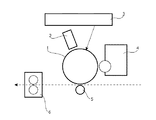
図1は、本発明の実施の形態に係る画像形成装置の機械的な構成を示す図である。 FIG. 1 is a diagram illustrating a mechanical configuration of an image forming apparatus according to an embodiment of the present invention.
図1に示すように本実施の形態に係る画像形成装置は、感光体ドラム1、一次帯電器2、露光装置3、現像装置4、転写ローラー5、および定着器6を備える。
As shown in FIG. 1, the image forming apparatus according to the present embodiment includes a
感光体ドラム1は、その表面に静電潜像を形成され、その静電潜像にトナーが付着してトナー像が形成される像担持体である。
The
一次帯電器2は、感光体ドラム1の表面を均一に帯電させる。
The primary charger 2 uniformly charges the surface of the
露光装置3は、レーザースキャナーを備え、レーザー光線を走査しつつ感光体ドラム1に照射し、印刷すべき画像に対応する静電潜像を感光体ドラム1上に形成する。
The
現像装置4は、トナーコンテナーから供給されるトナーを感光体ドラム1上の静電潜像に付着させてトナー像を形成する。
The developing device 4 forms a toner image by attaching the toner supplied from the toner container to the electrostatic latent image on the
転写ローラー5は、感光体ドラム1上のトナー像を印刷用紙へ転写する。
The
定着器6は、例えば加圧加熱方式で、印刷用紙上に転写されたトナー像を定着させる。
The
図2は、本発明の実施の形態に係る画像形成装置の電気的な構成を示すブロック図である。 FIG. 2 is a block diagram illustrating an electrical configuration of the image forming apparatus according to the embodiment of the present invention.
図2に示すように本実施の形態に係る画像形成装置は、さらに、冷却ファン21、ファン駆動回路22、操作パネル23、スピーカー駆動回路24、音解析部25、およびコントローラー26を備える。 As shown in FIG. 2, the image forming apparatus according to the present embodiment further includes a cooling fan 21, a fan drive circuit 22, an operation panel 23, a speaker drive circuit 24, a sound analysis unit 25, and a controller 26.
冷却ファン21は、当該画像形成装置の筐体表面に設置され、モーターで羽根を回転させることで筐体内の空気を排気し、筐体内部の温度を下げる。冷却ファン21の動作時には、モーターの振動音、羽根の風切り音などが発生する。 The cooling fan 21 is installed on the surface of the housing of the image forming apparatus, and exhausts air in the housing by rotating blades with a motor to lower the temperature inside the housing. During the operation of the cooling fan 21, vibration noise of the motor, wind noise of the blades, and the like are generated.
ファン駆動回路22は、制御信号に従って冷却ファン21(つまり、冷却ファン21のモーター)を駆動する。 The fan drive circuit 22 drives the cooling fan 21 (that is, the motor of the cooling fan 21) according to the control signal.
操作パネル23は、当該画像形成装置の筐体表面に設置され、ユーザーに対して各種情報を表示する表示装置やユーザー操作を受け付ける入力装置を備えるとともに、ユーザーに対して音を発するスピーカー23aを備える。 The operation panel 23 is provided on the surface of the housing of the image forming apparatus, and includes a display device for displaying various information to a user, an input device for receiving a user operation, and a speaker 23a for emitting a sound to the user. .
スピーカー駆動回路24は、制御信号に従って、操作確認音、ファクシミリ送受信の変調音、警告音などのオーディオ信号をスピーカー23aに出力する。 The speaker drive circuit 24 outputs audio signals such as an operation confirmation sound, a facsimile transmission / reception modulated sound, and a warning sound to the speaker 23a according to the control signal.
この実施の形態では、スピーカー駆動回路24によりオーディオ信号がスピーカー23aに出力されていないときに、スピーカー23aが、冷却ファン21の動作音を検出する音検出部として使用される。つまり、スピーカー駆動回路24によりスピーカー23aが駆動されていないときには、スピーカー23aに入る音に対応する電気信号(オーディオ信号)がスピーカー23aから出力される。なお、音検出部としては、スピーカー23aの代わりに、マイクロフォンなどを別途設置してもよい。 In this embodiment, when no audio signal is output to the speaker 23a by the speaker drive circuit 24, the speaker 23a is used as a sound detector that detects the operation sound of the cooling fan 21. That is, when the speaker 23a is not driven by the speaker driving circuit 24, an electric signal (audio signal) corresponding to the sound entering the speaker 23a is output from the speaker 23a. Note that a microphone or the like may be separately provided as the sound detection unit instead of the speaker 23a.
音解析部25は、音検出部(ここでは、スピーカー23a)により検出された冷却ファン21の動作音の音圧レベルおよび周波数を特定する。音解析部25は、例えば、ASIC(Application Specific Integrated Circuit)、プログラムを実行するCPU(Central Processing Unit)などを含むプロセッサーで実現される。 The sound analysis unit 25 specifies the sound pressure level and frequency of the operation sound of the cooling fan 21 detected by the sound detection unit (here, the speaker 23a). The sound analysis unit 25 is realized by a processor including, for example, an ASIC (Application Specific Integrated Circuit) and a CPU (Central Processing Unit) that executes a program.
コントローラー26は、上述の一次帯電器2、露光装置3、現像装置4、定着器6、および感光体ドラム1などを駆動する駆動装置11を制御する。コントローラー26は、例えば、音解析部25と同様に、ASIC、CPUなどを含むプロセッサーで実現される。また、コントローラー26は、スピーカー駆動回路24に制御信号を供給し、スピーカー23aに各種音を発せさせる。さらに、コントローラー26は、ファン駆動回路22に制御信号を供給し、その制御信号に基づいて、待機時における冷却ファン21の動作音の音圧レベルおよび周波数を制御し、これにより、例えば、冷却ファン21の動作音における可聴帯域の音圧レベルを所定の設定値以下にする。
The controller 26 controls the driving device 11 that drives the primary charger 2, the
例えば、コントローラー26は、駆動装置11などが停止している待機時に冷却ファン21を動作させて、音検出部(スピーカー23a)に冷却ファン21の動作音を検出させ、音解析部25は、そのときの冷却ファン21の動作音の音圧レベルおよび周波数を特定する。 For example, the controller 26 operates the cooling fan 21 in a standby state in which the driving device 11 or the like is stopped, causes the sound detection unit (speaker 23a) to detect the operation sound of the cooling fan 21, and the sound analysis unit 25 The sound pressure level and frequency of the operation sound of the cooling fan 21 at that time are specified.
この実施の形態では、さらに、コントローラー26は、ファン駆動回路22への制御信号を変化させて音解析部25により特定される冷却ファン21の動作音の音圧レベルおよび周波数を変動させ、それらの変動に基づいて、冷却ファン21の動作音における可聴帯域の音圧レベルが最小になる制御信号を特定し、待機時には、その特定した制御信号をファン駆動回路22に供給する。 In this embodiment, the controller 26 further changes the control signal to the fan drive circuit 22 to change the sound pressure level and frequency of the operation sound of the cooling fan 21 specified by the sound analysis unit 25, and Based on the fluctuation, a control signal that minimizes the sound pressure level of the audible band in the operation sound of the cooling fan 21 is specified, and the specified control signal is supplied to the fan drive circuit 22 during standby.
例えば、ファン駆動回路22は、PWM(Pulse Width Modulation)制御で冷却ファン21を駆動してもよく、その場合には、コントローラー26は、そのPWM制御のスイッチング周波数およびデューティなどを変化させたときに特定される動作音の音圧レベルの変動および周波数の変動に基づいて、待機時には、冷却ファン21の動作音における可聴帯域の音圧レベルが最小になるように、そのPWM制御のスイッチング周波数およびデューティなどを制御信号でファン駆動回路22に設定する。 For example, the fan driving circuit 22 may drive the cooling fan 21 by PWM (Pulse Width Modulation) control. In this case, the controller 26 changes the switching frequency and the duty of the PWM control. Based on the fluctuations in the sound pressure level and the frequency of the specified operation sound, the switching frequency and the duty of the PWM control are set such that the sound pressure level in the audible band of the operation sound of the cooling fan 21 is minimized during standby. Are set in the fan drive circuit 22 by a control signal.
次に、上記画像形成装置の動作について説明する。 Next, the operation of the image forming apparatus will be described.
印刷動作時においては、図1に示す各部が動作するため、装置内部の温度が上昇する。したがって、印刷動作時においては、コントローラー26は、ファン駆動回路22に、冷却ファン21を全速(100%)で駆動させる。 During the printing operation, since the components shown in FIG. 1 operate, the temperature inside the apparatus increases. Therefore, during the printing operation, the controller 26 causes the fan drive circuit 22 to drive the cooling fan 21 at full speed (100%).
一方、印刷を行わない待機時においては、装置内部の温度は比較的低いため、待機時においては、コントローラー26は、ファン駆動回路22に、冷却ファン21を所定の低速(例えば60%の速度)で駆動させる。 On the other hand, in the standby state where printing is not performed, the temperature inside the apparatus is relatively low. Therefore, in the standby state, the controller 26 causes the fan drive circuit 22 to send the cooling fan 21 to a predetermined low speed (for example, 60% speed). To drive.
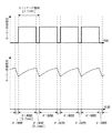
ここで、待機時における冷却ファン21の制御パターンの決定について説明する。図3および図4は、図2におけるファン駆動回路22により冷却ファン21のモーター印加電圧およびモーター導通電流の波形を説明する図である。 Here, determination of the control pattern of the cooling fan 21 during standby will be described. 3 and 4 are diagrams illustrating waveforms of a motor applied voltage and a motor conduction current of the cooling fan 21 by the fan drive circuit 22 in FIG.
例えば、待機時において、コントローラー26は、待機時の所定の回転速度を維持しつつ、ファン駆動回路22のPWM制御のスイッチング周波数およびデューティ並びに出力電圧(つまり、モーター印加電圧)の振幅を変化させて、音解析部25により特定される冷却ファン21の動作音の音圧レベルおよび周波数の変動を特定し、特定したそれらの変動に基づいて、冷却ファン21の動作音における可聴帯域の音圧レベルが最小になるスイッチング周波数およびデューティ並びに振幅を特定し、その後、待機時には、特定したスイッチング周波数およびデューティ並びに振幅を指定する制御信号をファン駆動回路22に供給し、冷却ファン21を動作させる。 For example, during standby, the controller 26 changes the switching frequency and duty of the PWM control of the fan drive circuit 22 and the amplitude of the output voltage (that is, the motor applied voltage) while maintaining the predetermined rotation speed during standby. The sound pressure level and the frequency of the operation sound of the cooling fan 21 specified by the sound analysis unit 25 are specified, and the sound pressure level of the audible band in the operation sound of the cooling fan 21 is determined based on the specified change. The minimum switching frequency, duty and amplitude are specified, and then, during standby, a control signal specifying the specified switching frequency, duty and amplitude is supplied to the fan drive circuit 22 to operate the cooling fan 21.
例えば図3に示す場合では、ファン駆動回路22は、オン期間を1.8秒としオフ期間を1.2秒としたPWM制御で冷却ファン21のモーターを駆動し、これにより、冷却ファン21は約60%の回転速度で動作する。 For example, in the case shown in FIG. 3, the fan drive circuit 22 drives the motor of the cooling fan 21 by PWM control in which the ON period is 1.8 seconds and the OFF period is 1.2 seconds. It operates at a rotation speed of about 60%.
図3に示す場合、オン期間のモーター導通電流の最大値とオフ期間のモーター導通電流の最小値との差が大きいため、冷却ファン21の回転速度のムラが大きい。そのため、可聴帯域の音圧レベルが高くなり、ユーザーの感じる騒音が大きい可能性がある。 In the case shown in FIG. 3, since the difference between the maximum value of the motor conduction current during the ON period and the minimum value of the motor conduction current during the OFF period is large, the rotation speed of the cooling fan 21 is largely uneven. Therefore, the sound pressure level in the audible band is increased, and there is a possibility that the noise felt by the user is large.
他方、例えば図4に示す場合では、図3に示す場合とは異なるスイッチング周期(つまり異なるスイッチング周波数)および異なるデューティが設定され、ファン駆動回路22は、オン期間を1.7秒としオフ期間を0.3秒としたPWM制御で冷却ファン21のモーターを駆動する。これにより、図3に示す場合に比べ、オン期間のモーター導通電流の最大値とオフ期間のモーター導通電流の最小値との差が小さくなり、冷却ファン21の回転速度のムラが小さくなる。そのため、可聴帯域の音圧レベルが低くなり、図3に示す場合に比べユーザーの感じる騒音が小さくなる。 On the other hand, in the case shown in FIG. 4, for example, a switching cycle (that is, a different switching frequency) and a different duty different from those shown in FIG. 3 are set, and the fan drive circuit 22 sets the ON period to 1.7 seconds and sets the OFF period to The motor of the cooling fan 21 is driven by the PWM control for 0.3 seconds. As a result, the difference between the maximum value of the motor conduction current during the ON period and the minimum value of the motor conduction current during the OFF period becomes smaller than in the case shown in FIG. 3, and the unevenness in the rotational speed of the cooling fan 21 becomes smaller. Therefore, the sound pressure level in the audible band is reduced, and the noise felt by the user is smaller than in the case shown in FIG.
このようにして、コントローラー26は、複数の制御パターン(スイッチング周波数およびデューティなど)でファン駆動回路22に冷却ファン21を動作させ、そのときに、音検出部(スピーカー23a)および音解析部25を使用して可聴帯域の音圧レベルを測定し、可聴帯域の音圧レベルが最小となる制御パターンを特定する。そして、待機時には、コントローラー26は、特定した制御パターンを制御信号でファン駆動回路22に指定して、低速で冷却ファン21を動作させる。 In this manner, the controller 26 causes the fan drive circuit 22 to operate the cooling fan 21 with a plurality of control patterns (switching frequency, duty, etc.), and at this time, the sound detection unit (speaker 23a) and the sound analysis unit 25 It is used to measure the sound pressure level in the audible band, and to specify a control pattern that minimizes the sound pressure level in the audible band. Then, during standby, the controller 26 specifies the specified control pattern to the fan drive circuit 22 by a control signal and operates the cooling fan 21 at a low speed.
以上のように、上記実施の形態によれば、ファン駆動回路22は、制御信号に従って冷却ファン21を駆動する。音検出部(スピーカー23a)は、冷却ファン21の動作音を検出する。音解析部25は、その音検出部により検出された動作音の音圧レベルおよび周波数を特定する。コントローラー26は、ファン駆動回路22に制御信号を供給し、その制御信号に基づいて、待機時における冷却ファン21の動作音の音圧レベルおよび周波数を制御する。 As described above, according to the above embodiment, the fan drive circuit 22 drives the cooling fan 21 according to the control signal. The sound detection unit (speaker 23a) detects an operation sound of the cooling fan 21. The sound analyzer 25 specifies the sound pressure level and frequency of the operation sound detected by the sound detector. The controller 26 supplies a control signal to the fan drive circuit 22, and controls the sound pressure level and frequency of the operation sound of the cooling fan 21 during standby based on the control signal.
これにより、待機時には、印刷動作に起因する動作音が発生しないため、冷却ファン21の音が聞き取られやすくなるが、上述のように冷却ファン21の動作音の音圧レベルおよび周波数が制御されるため、待機時における冷却ファン21に起因する騒音が効果的に軽減される。 As a result, in the standby state, since the operation sound due to the printing operation is not generated, the sound of the cooling fan 21 is easily heard, but the sound pressure level and the frequency of the operation sound of the cooling fan 21 are controlled as described above. Therefore, noise caused by the cooling fan 21 during standby is effectively reduced.
なお、上述の実施の形態に対する様々な変更および修正については、当業者には明らかである。そのような変更および修正は、その主題の趣旨および範囲から離れることなく、かつ、意図された利点を弱めることなく行われてもよい。つまり、そのような変更および修正が請求の範囲に含まれることを意図している。 Various changes and modifications to the above-described embodiment will be apparent to those skilled in the art. Such changes and modifications may be made without departing from the spirit and scope of the subject matter and without diminishing its intended advantages. That is, such changes and modifications are intended to be included in the scope of the claims.
例えば、上記実施の形態において、コントローラー26は、冷却ファン21の複数の制御パターンを予め設定しておき、その複数の制御パターンから、ユーザー操作や上述の動作音の可聴帯域の音圧レベルの測定値に基づいて1つの制御パターンを選択し、その制御パターンで、ファン駆動回路22を動作させるようにしてもよい。 For example, in the above-described embodiment, the controller 26 sets a plurality of control patterns of the cooling fan 21 in advance, and measures the sound pressure level of the audible band of the user operation or the operation sound from the plurality of control patterns. One control pattern may be selected based on the value, and the fan drive circuit 22 may be operated with the selected control pattern.
本発明は、例えば、画像形成装置に適用可能である。 The present invention is applicable to, for example, an image forming apparatus.
21 冷却ファン
22 ファン駆動回路
23 操作パネル
23a スピーカー(音検出部の一例)
25 音解析部
26 コントローラー
21 cooling fan 22 fan drive circuit 23 operation panel 23a speaker (an example of a sound detection unit)
25 Sound analysis unit 26 Controller
Claims (2)
制御信号に従って前記冷却ファンを駆動するファン駆動回路と、
前記冷却ファンの動作音を検出する音検出部と、
前記音検出部により検出された前記動作音の音圧レベルおよび周波数を特定する音解析部と、
前記ファン駆動回路に前記制御信号を供給し、前記制御信号に基づいて、待機時における前記動作音の音圧レベルおよび周波数を制御するコントローラーと、
を備え、
前記ファン駆動回路は、PWM制御で前記冷却ファンを駆動し、
前記コントローラーは、(a)待機時の所定の回転速度を維持しつつ、前記ファン駆動回路のPWM制御のスイッチング周波数およびデューティ並びに前記冷却ファンへの出力電圧の振幅を変化させて、前記音解析部により特定される前記冷却ファンの動作音の音圧レベルおよび周波数の変動を特定し、(b)特定した前記変動に基づいて、前記冷却ファンの回転速度ムラが小さく前記冷却ファンの動作音における可聴帯域の音圧レベルが最小になるスイッチング周波数およびデューティ並びに振幅を特定し、(c)待機時には、特定した前記スイッチング周波数および前記デューティ並びに前記振幅を指定する制御信号を前記ファン駆動回路に供給し、前記冷却ファンを動作させること、
を特徴とする画像形成装置。 A cooling fan,
A fan drive circuit that drives the cooling fan according to a control signal;
A sound detection unit that detects an operation sound of the cooling fan,
A sound analysis unit that specifies the sound pressure level and frequency of the operation sound detected by the sound detection unit,
A controller that supplies the control signal to the fan drive circuit and controls a sound pressure level and a frequency of the operation sound during standby based on the control signal,
Equipped with a,
The fan drive circuit drives the cooling fan by PWM control,
The controller (a) changes a switching frequency and a duty of PWM control of the fan drive circuit and an amplitude of an output voltage to the cooling fan while maintaining a predetermined rotation speed during standby, and (B) based on the specified fluctuation, the rotation speed unevenness of the cooling fan is small, and the audible sound of the operation sound of the cooling fan is specified. (C) during standby, supplying a control signal specifying the specified switching frequency, duty, and amplitude to the fan drive circuit, Operating the cooling fan;
An image forming apparatus comprising:
前記冷却ファンおよび前記操作パネルは、当該画像形成装置の筐体表面に設置されており、
前記スピーカーが前記音検出部として使用されること、
を特徴とする請求項1記載の画像形成装置。 Further comprising an operation panel having a speaker that emits a sound to the user,
The cooling fan and the operation panel are installed on a housing surface of the image forming apparatus,
The speaker is used as the sound detector,
The image forming apparatus according to claim 1 Symbol mounting characterized.
Priority Applications (1)
| Application Number | Priority Date | Filing Date | Title |
|---|---|---|---|
| JP2017015404A JP6674635B2 (en) | 2017-01-31 | 2017-01-31 | Image forming device |
Applications Claiming Priority (1)
| Application Number | Priority Date | Filing Date | Title |
|---|---|---|---|
| JP2017015404A JP6674635B2 (en) | 2017-01-31 | 2017-01-31 | Image forming device |
Publications (2)
| Publication Number | Publication Date |
|---|---|
| JP2018124375A JP2018124375A (en) | 2018-08-09 |
| JP6674635B2 true JP6674635B2 (en) | 2020-04-01 |
Family
ID=63111292
Family Applications (1)
| Application Number | Title | Priority Date | Filing Date |
|---|---|---|---|
| JP2017015404A Expired - Fee Related JP6674635B2 (en) | 2017-01-31 | 2017-01-31 | Image forming device |
Country Status (1)
| Country | Link |
|---|---|
| JP (1) | JP6674635B2 (en) |
Family Cites Families (17)
| Publication number | Priority date | Publication date | Assignee | Title |
|---|---|---|---|---|
| JP2874907B2 (en) * | 1989-08-25 | 1999-03-24 | 株式会社東芝 | Image forming device |
| JP3308077B2 (en) * | 1993-12-13 | 2002-07-29 | 株式会社リコー | Fan control method |
| JPH07271384A (en) * | 1994-04-01 | 1995-10-20 | Ricoh Co Ltd | Blower |
| JPH10232163A (en) * | 1997-02-20 | 1998-09-02 | Fuji Xerox Co Ltd | Device and method for evaluating tone quality |
| JP2001236001A (en) * | 2000-02-25 | 2001-08-31 | Canon Inc | Image forming apparatus and control method thereof |
| JP2004129125A (en) * | 2002-10-07 | 2004-04-22 | Matsushita Electric Ind Co Ltd | Speaker system |
| JP2004157463A (en) * | 2002-11-08 | 2004-06-03 | Brother Ind Ltd | Image forming device |
| JP4890935B2 (en) * | 2006-02-15 | 2012-03-07 | 株式会社リコー | Waste heat structure and image forming apparatus |
| JP2008225321A (en) * | 2007-03-15 | 2008-09-25 | Canon Inc | Image forming apparatus |
| US7873287B2 (en) * | 2007-03-30 | 2011-01-18 | Kabushiki Kaisha Toshiba | Image forming apparatus addressing an abnormality in the cooling device and a method of controlling the image forming apparatus |
| JP2009169250A (en) * | 2008-01-18 | 2009-07-30 | Toshiba Tec Corp | State management device and state management method |
| JP2009193370A (en) * | 2008-02-14 | 2009-08-27 | Ricoh Co Ltd | Information processing apparatus, information processing apparatus control method, information processing apparatus manufacturing method, control program, and recording medium |
| JP5099841B2 (en) * | 2008-04-18 | 2012-12-19 | 株式会社リコー | Image forming apparatus |
| JP2011007978A (en) * | 2009-06-25 | 2011-01-13 | Canon Inc | Image forming apparatus |
| JP2012141547A (en) * | 2011-01-06 | 2012-07-26 | Canon Inc | Image forming apparatus |
| WO2012176339A1 (en) * | 2011-06-24 | 2012-12-27 | 富士通株式会社 | Monitoring processing device, electronic system, method for controlling electronic system, and program for controlling monitoring processing device |
| JP6289164B2 (en) * | 2014-02-27 | 2018-03-07 | キヤノン株式会社 | Image forming apparatus |
-
2017
- 2017-01-31 JP JP2017015404A patent/JP6674635B2/en not_active Expired - Fee Related
Also Published As
| Publication number | Publication date |
|---|---|
| JP2018124375A (en) | 2018-08-09 |
Similar Documents
| Publication | Publication Date | Title |
|---|---|---|
| CN101827661B (en) | Mobile device comprising a vibrator and an accelerometer to control the performance of said vibrator | |
| US8577231B2 (en) | Image forming apparatus and toner sensor status sensing method thereof | |
| JP6674635B2 (en) | Image forming device | |
| JP2005287206A (en) | Motor control apparatus and image forming apparatus | |
| JPH10186825A (en) | Image forming device | |
| JPH068581A (en) | Noise prevention mechanism for image forming apparatus | |
| JPH0535050A (en) | Charging device and process cartridge or image forming apparatus having charging device | |
| JP2015011160A (en) | Image forming apparatus | |
| JP2022018990A (en) | Information processing apparatus, operation adjustment method thereof, and program | |
| JP5509145B2 (en) | Image forming apparatus | |
| JP2018051983A (en) | Portable device and image forming system | |
| JP7575264B2 (en) | Audio output device | |
| JP5789688B2 (en) | Image forming apparatus | |
| JP6372706B2 (en) | Image forming apparatus | |
| CN111526432A (en) | Electronic device, control method thereof, computer device, and readable storage medium | |
| JP2014206609A (en) | Sound output device and image forming apparatus using the same | |
| JP2019174726A (en) | Image formation apparatus | |
| JP2007074525A (en) | Image processor | |
| JP2022116987A (en) | Electronic apparatus | |
| JP2011191636A (en) | Image forming apparatus and fan control method | |
| JP2019142072A (en) | Electronic apparatus, image forming device, and program | |
| JP2007114376A5 (en) | ||
| JP2024093307A (en) | Switching power supply and image forming apparatus | |
| JP5453339B2 (en) | Developing device and image forming apparatus | |
| JP2016120674A (en) | Image forming apparatus |
Legal Events
| Date | Code | Title | Description |
|---|---|---|---|
| A621 | Written request for application examination |
Free format text: JAPANESE INTERMEDIATE CODE: A621 Effective date: 20181029 |
|
| A977 | Report on retrieval |
Free format text: JAPANESE INTERMEDIATE CODE: A971007 Effective date: 20190823 |
|
| A131 | Notification of reasons for refusal |
Free format text: JAPANESE INTERMEDIATE CODE: A131 Effective date: 20190905 |
|
| A521 | Request for written amendment filed |
Free format text: JAPANESE INTERMEDIATE CODE: A523 Effective date: 20191024 |
|
| TRDD | Decision of grant or rejection written | ||
| A01 | Written decision to grant a patent or to grant a registration (utility model) |
Free format text: JAPANESE INTERMEDIATE CODE: A01 Effective date: 20200206 |
|
| A61 | First payment of annual fees (during grant procedure) |
Free format text: JAPANESE INTERMEDIATE CODE: A61 Effective date: 20200219 |
|
| R150 | Certificate of patent or registration of utility model |
Ref document number: 6674635 Country of ref document: JP Free format text: JAPANESE INTERMEDIATE CODE: R150 |
|
| LAPS | Cancellation because of no payment of annual fees |