JP6674397B2 - Acceleration sensor - Google Patents
Acceleration sensor Download PDFInfo
- Publication number
- JP6674397B2 JP6674397B2 JP2017028316A JP2017028316A JP6674397B2 JP 6674397 B2 JP6674397 B2 JP 6674397B2 JP 2017028316 A JP2017028316 A JP 2017028316A JP 2017028316 A JP2017028316 A JP 2017028316A JP 6674397 B2 JP6674397 B2 JP 6674397B2
- Authority
- JP
- Japan
- Prior art keywords
- conductive layer
- acceleration sensor
- movable
- mechanical joint
- gap
- Prior art date
- Legal status (The legal status is an assumption and is not a legal conclusion. Google has not performed a legal analysis and makes no representation as to the accuracy of the status listed.)
- Active
Links
Images


Classifications
-
- G—PHYSICS
- G01—MEASURING; TESTING
- G01P—MEASURING LINEAR OR ANGULAR SPEED, ACCELERATION, DECELERATION, OR SHOCK; INDICATING PRESENCE, ABSENCE, OR DIRECTION, OF MOVEMENT
- G01P15/00—Measuring acceleration; Measuring deceleration; Measuring shock, i.e. sudden change of acceleration
- G01P15/02—Measuring acceleration; Measuring deceleration; Measuring shock, i.e. sudden change of acceleration by making use of inertia forces using solid seismic masses
- G01P15/08—Measuring acceleration; Measuring deceleration; Measuring shock, i.e. sudden change of acceleration by making use of inertia forces using solid seismic masses with conversion into electric or magnetic values
- G01P15/125—Measuring acceleration; Measuring deceleration; Measuring shock, i.e. sudden change of acceleration by making use of inertia forces using solid seismic masses with conversion into electric or magnetic values by capacitive pick-up
-
- G—PHYSICS
- G01—MEASURING; TESTING
- G01P—MEASURING LINEAR OR ANGULAR SPEED, ACCELERATION, DECELERATION, OR SHOCK; INDICATING PRESENCE, ABSENCE, OR DIRECTION, OF MOVEMENT
- G01P15/00—Measuring acceleration; Measuring deceleration; Measuring shock, i.e. sudden change of acceleration
- G01P15/02—Measuring acceleration; Measuring deceleration; Measuring shock, i.e. sudden change of acceleration by making use of inertia forces using solid seismic masses
- G01P15/08—Measuring acceleration; Measuring deceleration; Measuring shock, i.e. sudden change of acceleration by making use of inertia forces using solid seismic masses with conversion into electric or magnetic values
- G01P15/097—Measuring acceleration; Measuring deceleration; Measuring shock, i.e. sudden change of acceleration by making use of inertia forces using solid seismic masses with conversion into electric or magnetic values by vibratory elements
-
- G—PHYSICS
- G01—MEASURING; TESTING
- G01P—MEASURING LINEAR OR ANGULAR SPEED, ACCELERATION, DECELERATION, OR SHOCK; INDICATING PRESENCE, ABSENCE, OR DIRECTION, OF MOVEMENT
- G01P15/00—Measuring acceleration; Measuring deceleration; Measuring shock, i.e. sudden change of acceleration
- G01P15/02—Measuring acceleration; Measuring deceleration; Measuring shock, i.e. sudden change of acceleration by making use of inertia forces using solid seismic masses
- G01P15/08—Measuring acceleration; Measuring deceleration; Measuring shock, i.e. sudden change of acceleration by making use of inertia forces using solid seismic masses with conversion into electric or magnetic values
- G01P2015/0805—Measuring acceleration; Measuring deceleration; Measuring shock, i.e. sudden change of acceleration by making use of inertia forces using solid seismic masses with conversion into electric or magnetic values being provided with a particular type of spring-mass-system for defining the displacement of a seismic mass due to an external acceleration
- G01P2015/0822—Measuring acceleration; Measuring deceleration; Measuring shock, i.e. sudden change of acceleration by making use of inertia forces using solid seismic masses with conversion into electric or magnetic values being provided with a particular type of spring-mass-system for defining the displacement of a seismic mass due to an external acceleration for defining out-of-plane movement of the mass
- G01P2015/0825—Measuring acceleration; Measuring deceleration; Measuring shock, i.e. sudden change of acceleration by making use of inertia forces using solid seismic masses with conversion into electric or magnetic values being provided with a particular type of spring-mass-system for defining the displacement of a seismic mass due to an external acceleration for defining out-of-plane movement of the mass for one single degree of freedom of movement of the mass
- G01P2015/0831—Measuring acceleration; Measuring deceleration; Measuring shock, i.e. sudden change of acceleration by making use of inertia forces using solid seismic masses with conversion into electric or magnetic values being provided with a particular type of spring-mass-system for defining the displacement of a seismic mass due to an external acceleration for defining out-of-plane movement of the mass for one single degree of freedom of movement of the mass the mass being of the paddle type having the pivot axis between the longitudinal ends of the mass, e.g. see-saw configuration
Landscapes
- Physics & Mathematics (AREA)
- General Physics & Mathematics (AREA)
- Pressure Sensors (AREA)
- Geophysics And Detection Of Objects (AREA)
- Micromachines (AREA)
Description
本発明は、加速度センサに関し、例えば微小な振動加速度を検出する加速度センサに関する。 The present invention relates to an acceleration sensor, for example, to an acceleration sensor that detects a small vibration acceleration.
地下資源探査の分野において、加速度センサを用いた反射法弾性波探査が行われる。反射法弾性波探査とは、物理探査の一種であり、人工的に地震波を発生させ、地表に設置された受振器により地下から跳ね返ってくる反射波を捉え、その結果を解析して地下構造を解明する方法である。 2. Description of the Related Art In the field of underground resource exploration, reflection acoustic wave exploration using an acceleration sensor is performed. Reflection acoustic wave exploration is a type of physical exploration, which artificially generates seismic waves, captures reflected waves that bounce off the ground using a geophone installed on the surface, analyzes the results, and analyzes the underground structure. It is a way to elucidate.
反射法弾性波探査では、地表に設置された起振源から地中に弾性波を励振し、地層の境界で反射した弾性波を、地表に設置された受振器でセンシングする。さまざまな方向に励振された弾性波は、減衰の大きい地中を伝搬し、複数の地層で反射し、再び減衰の大きい地中を伝搬し、広い領域に拡散して地表に戻ってくる。 In the reflection method acoustic wave survey, an elastic wave is excited into the ground from a vibration source installed on the ground surface, and the elastic wave reflected at the boundary of the stratum is sensed by a geophone installed on the ground surface. Elastic waves excited in various directions propagate through the ground with large attenuation, are reflected by a plurality of strata, propagate through the ground with large attenuation again, diffuse over a wide area, and return to the surface of the earth.
従って、反射法弾性波探査に用いられる加速度センサは、鉛直方向、すなわち重力加速度と同じ方向に印加され、かつ、重力加速度より小さい加速度を検出する必要がある。すなわち、反射法弾性波探査に用いられる加速度センサでは、鉛直方向の加速度の感度を向上させる必要がある。 Therefore, the acceleration sensor used for the reflection acoustic wave exploration needs to detect an acceleration applied in the vertical direction, that is, the same direction as the gravitational acceleration, and smaller than the gravitational acceleration. That is, it is necessary to improve the sensitivity of the acceleration in the vertical direction in the acceleration sensor used for the reflection acoustic wave exploration.
本技術分野の背景技術として、特開2016−070817号公報(特許文献1)がある。この公報には、第1可動部と第2可動部とを電気的に分離しながらも、機械的接合部によって機械的に接続することにより、第1MEMS素子の静電容量と第2MEMS素子の静電容量とのずれを制御することのできる慣性センサが記載されている。 As a background art of the present technical field, there is Japanese Patent Application Laid-Open No. 2006-070817 (Patent Document 1). This publication discloses that while the first movable portion and the second movable portion are electrically separated from each other, they are mechanically connected by a mechanical joining portion, so that the electrostatic capacity of the first MEMS element and the static electricity of the second MEMS element are reduced. An inertial sensor capable of controlling a deviation from a capacitance is described.
反射法弾性波探査に用いられる加速度センサでは、加速度の感度を向上させるために、1個のメンブレン(質量体)に4個の検出電極を設置している。 In the acceleration sensor used for the reflection-type elastic wave exploration, four detection electrodes are provided on one membrane (mass) in order to improve the sensitivity of acceleration.
しかし、メンブレンをハウジングまたは実装する際に、メンブレンに応力が印加されてメンブレンが湾曲し、検出電極の容量値がばらつくことがある。詳細に検討した結果、検出電極の容量値がばらつくと、サーボ制御が不安定になり、さらに雑音が増加して、高精度な加速度センサが実現できないことが明らかとなった。 However, when the membrane is mounted or mounted on the membrane, stress may be applied to the membrane, causing the membrane to bend and the capacitance value of the detection electrode to vary. As a result of a detailed study, it was found that if the capacitance value of the detection electrode varies, the servo control becomes unstable and the noise further increases, so that a highly accurate acceleration sensor cannot be realized.
そこで、本発明は、検出電極の容量値のばらつきを低減することにより、安定に動作して、雑音特性に優れた高精度な加速度センサを提供する。 Thus, the present invention provides a highly accurate acceleration sensor that operates stably and has excellent noise characteristics by reducing the variation in the capacitance value of the detection electrode.
上記課題を解決するために、本発明は、第1基板と、第1基板から第1方向に離間して設けられた第2基板と、第1基板と第2基板との間に設けられた第1方向に変位可能な質量体と、を備える加速度センサである。質量体は、第1可動部と、第1可動部と電気的に分離された第2可動部と、第1可動部と第2可動部とを第1方向と直交する第2方向に機械的に接続する機械的接合部と、を有し、機械的接合部は、第1方向と直交する平面において、第2方向に対して第1角度を有する方向に延伸する第1部分と、第2方向に対して第1角度と異なる第2角度を有する方向に延伸する第2部分と、を有する。 In order to solve the above problems, the present invention provides a first substrate, a second substrate provided in a first direction apart from the first substrate, and a first substrate provided between the first substrate and the second substrate. A mass body displaceable in a first direction. The mass body mechanically connects the first movable section, the second movable section electrically separated from the first movable section, and the first movable section and the second movable section in a second direction orthogonal to the first direction. A first portion extending in a direction perpendicular to the first direction in a direction having a first angle with respect to the second direction; and a second portion extending in a plane orthogonal to the first direction. A second portion extending in a direction having a second angle different from the first angle with respect to the direction.
本発明によれば、検出電極の容量値のばらつきを低減することにより、安定に動作して、雑音特性に優れた高精度な加速度センサを提供することができる。 According to the present invention, it is possible to provide a high-accuracy acceleration sensor that operates stably and has excellent noise characteristics by reducing the variation in the capacitance value of the detection electrode.
上記した以外の課題、構成および効果は、以下の実施の形態の説明により明らかにされる。 Problems, configurations, and effects other than those described above will be apparent from the following description of the embodiments.
以下、実施の形態を図面に基づいて詳細に説明する。なお、実施の形態を説明するための全図において、同一の機能を有する部材には同一または関連する符号を付し、その繰り返しの説明は省略する。また、複数の類似の部材(部位)が存在する場合には、総称の符号に記号を追加し個別または特定の部位を示す場合がある。また、以下の実施の形態では、特に必要なとき以外は同一または同様な部分の説明を原則として繰り返さない。 Hereinafter, embodiments will be described in detail with reference to the drawings. In all the drawings for describing the embodiments, members having the same functions are denoted by the same or related reference numerals, and repeated description thereof will be omitted. When there are a plurality of similar members (parts), a symbol may be added to a generic name to indicate an individual or specific part. In the following embodiments, the description of the same or similar parts will not be repeated in principle except when necessary.
また、実施の形態で用いる図面においては、断面図であっても図面を見易くするためにハッチングを省略する場合もある。また、平面図であっても図面を見易くするためにハッチングを付す場合もある。 Also, in the drawings used in the embodiments, hatching may be omitted even in a cross-sectional view so as to make the drawings easy to see. Also, hatching may be used even in a plan view so as to make the drawings easy to see.
また、断面図および平面図において、各部位の大きさは実デバイスと対応するものではなく、図面を分かりやすくするため、特定の部位を相対的に大きく表示する場合がある。また、断面図と平面図が対応する場合においても、図面を分かりやすくするため、特定の部位を相対的に大きく表示する場合がある。 In the cross-sectional view and the plan view, the size of each part does not correspond to the size of an actual device, and a specific part may be displayed relatively large for easy understanding of the drawing. Further, even when the sectional view and the plan view correspond to each other, a specific portion may be displayed relatively large in order to make the drawing easy to understand.
<反射法弾性波探査法>
初めに、地下資源探査の分野で行われる、加速度センサを用いた反射法弾性波探査について説明する。反射法弾性波探査とは、物理探査の一種であり、人工的に地震波を発生させ、地表に設置した受振器により地下から跳ね返ってくる反射波を捉え、その結果を解析して地下構造を解明する方法である。
<Reflection elastic wave exploration method>
First, reflection acoustic wave exploration using an acceleration sensor performed in the field of underground resource exploration will be described. Reflection acoustic wave exploration is a type of physical exploration that artificially generates seismic waves, uses a geophone installed on the ground to capture reflected waves that bounce off the ground, and analyzes the results to elucidate the underground structure. How to
図1は、反射法弾性波探査の概要を示した地表の断面模式図である。 FIG. 1 is a schematic cross-sectional view of the ground surface showing the outline of the reflection acoustic wave survey.
図1に示すように、反射法弾性波探査では、地表G3に設置された起振源G1から地中に弾性波(図1中に矢印で示す。)を励振し、地層の境界G4a,G4bのいずれかで反射した弾性波を、地表G3に設置された受振器G2a,G2b,G2c,G2d,G2eのいずれかでセンシングする。 As shown in FIG. 1, in the reflection method elastic wave exploration, an elastic wave (indicated by an arrow in FIG. 1) is excited from the excitation source G1 installed on the ground surface G3 into the ground, and the boundary G4a, G4b of the stratum. Is sensed by any of the geophones G2a, G2b, G2c, G2d, and G2e installed on the ground surface G3.
一般的な起振源G1は地表G3に対して垂直方向に発振するため、鉛直に近い方向にP波が効率よく励振される。そのため、反射法弾性波探査では、P波を用いる。また、再び地表G3に戻ってくる弾性波は、鉛直方向に近い方向から伝搬してくるP波であるため、受振器G2a,G2b,G2c,G2d,G2eは鉛直方向の弾性振動を検知する必要がある。 Since the general excitation source G1 oscillates in a direction perpendicular to the ground surface G3, the P wave is efficiently excited in a direction close to the vertical. Therefore, the P wave is used in the reflection acoustic wave survey. Since the elastic wave returning to the ground surface G3 is a P wave propagating from a direction close to the vertical direction, the geophones G2a, G2b, G2c, G2d, and G2e need to detect the vertical elastic vibration. There is.
さまざまな方向に励振された弾性波は、減衰の大きい地中を伝搬し、複数の地層の境界G4a,G4bで反射し、再び減衰の大きい地中を伝搬し、広い領域に拡散して地表G3に戻ってくる。 The elastic waves excited in various directions propagate through the ground with large attenuation, are reflected at boundaries G4a and G4b of a plurality of strata, propagate through the ground with large attenuation again, diffuse into a wide area, and spread to the ground G3. Come back to.
微弱な弾性振動を検知するため、受振器G2a,G2b,G2c,G2d,G2eとして、鉛直方向に高感度な加速度センサを用いる必要がある。従って、受振器G2a,G2b,G2c,G2d,G2eとして、以下に説明する本実施例1、2および3による加速度センサを用いることが望ましい。 In order to detect a weak elastic vibration, it is necessary to use an acceleration sensor having high sensitivity in the vertical direction as the geophones G2a, G2b, G2c, G2d, and G2e. Therefore, it is desirable to use the acceleration sensors according to the first, second, and third embodiments described below as the geophones G2a, G2b, G2c, G2d, and G2e.
<加速度センサの構成>
本実施例1による加速度センサの構成について、図2〜図8を参照しながら説明する。
<Configuration of acceleration sensor>
The configuration of the acceleration sensor according to the first embodiment will be described with reference to FIGS.
図2〜図4は、本実施例1による加速度センサの断面図である。図5〜図8は、本実施例1による加速度センサの平面図である。 2 to 4 are cross-sectional views of the acceleration sensor according to the first embodiment. 5 to 8 are plan views of the acceleration sensor according to the first embodiment.
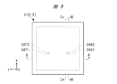
図2は、図5〜図8のA−A線に沿った断面図である。図3は、図5〜図8のB−B線に沿った断面図である。図4は、図5〜図8のC−C線に沿った断面図である。図5は、図2〜図4のD−D線に沿った平面図であり、メンブレン層の上面を示す平面図である。図6は、図2〜図4のG−G線に沿った平面図であり、メンブレン層の下面を示す平面図である。図7は、図2〜図4のE−E線に沿った平面図であり、キャップ層の下面を示す平面図である。図8は、図2〜図4のF−F線に沿った平面図であり、ベース層の上面を示す平面図である。 FIG. 2 is a cross-sectional view taken along line AA of FIGS. FIG. 3 is a cross-sectional view taken along line BB of FIGS. FIG. 4 is a cross-sectional view taken along line CC of FIGS. FIG. 5 is a plan view taken along line DD of FIGS. 2 to 4 and is a plan view showing the upper surface of the membrane layer. FIG. 6 is a plan view along the line GG in FIGS. 2 to 4 and is a plan view showing the lower surface of the membrane layer. FIG. 7 is a plan view taken along the line EE in FIGS. 2 to 4 and is a plan view showing the lower surface of the cap layer. FIG. 8 is a plan view along the line FF in FIGS. 2 to 4, and is a plan view showing the upper surface of the base layer.
本実施例1による加速度センサS1は、ベース層BasL、メンブレン層MemLおよびキャップ層CapLの積層から構成されており、実装基板層SubL上に実装されている。 The acceleration sensor S1 according to the first embodiment is configured by stacking a base layer BasL, a membrane layer MemL, and a cap layer CapL, and is mounted on the mounting substrate layer SubL.
以下の説明では、平面視において、互いに交差、好適には直交する2つの方向をx軸方向およびy軸方向とし、実装基板層SubLの主面に垂直な方向をz軸方向とする。また、「平面視において」とは、実装基板層SubLの主面としての上面に垂直な方向であるz軸方向から見た場合を意味する。 In the following description, in a plan view, two directions that intersect, preferably perpendicular to each other, are defined as an x-axis direction and a y-axis direction, and a direction perpendicular to the main surface of the mounting substrate layer SubL is defined as a z-axis direction. Further, “in a plan view” means a case when viewed from the z-axis direction which is a direction perpendicular to the upper surface as the main surface of the mounting substrate layer SubL.
図2〜図4および図7に示すように、キャップ層CapLは、絶縁物11、空洞13および固定電極12TL,12TR,12BL,12BRによって構成されている。絶縁物11は、メンブレン層MemLの側部35および固定部34T1,34T2,34B1,34B2(図5参照)との接合部以外の部分に、下面に凹部が形成され、さらに、凹部に固定電極12TL,12TR,12BL,12BRが設置されている。絶縁物11は、メンブレン層MemLの上部に設置されているため、空洞13を密閉するキャップとして機能する。また、固定電極12TL,12TRは、メンブレン層MemLに形成された可動部(可動電極)32TDと対になって可変容量の固定電極として機能し、固定電極12BL,12BRは、メンブレン層MemLに形成された可動部(可動電極)32BDと対になって可変容量の固定電極として機能する。
As shown in FIG. 2 to FIG. 4 and FIG. 7, the cap layer CapL includes an
図2〜図4、図5および図6に示すように、メンブレン層MemLは、メンブレン(質量体)32、ねじれバネ33T1,33T2,33B1,33B2、固定部34T1,34T2,34B1,34B2および側部35で構成されている。側部35は、空洞13を密閉する側部として機能する。
As shown in FIGS. 2 to 4, 5 and 6, the membrane layer MemL includes a membrane (mass body) 32, torsion springs 33
メンブレン32は、導電層32DL、絶縁物32Iおよび導電層32HLで構成されている。さらに、導電層32DLは、可動部32TD,32BDを構成し、導電層32HLは、可動部32TH,32BHおよび導電物32mDを構成し、それらは機械的に一体化されている。可動部32TDは、キャップ層CapLに形成された固定電極12TL,12TRと対になって可変容量の可動電極として機能する。可動部32BDは、キャップ層CapLに形成された固定電極12BL,12BRと対になって可変容量の可動電極として機能する。可動部32TH,32BHは、メンブレン32の機械的強度を高くする補強物として機能する。
The
なお、導電層32DL、絶縁物32Iおよび導電層32HLには、開口部が形成されている場合がある。本実施の形態では、開口部の有無に関係なく効果があるため、以下の説明では、開口部を省略する。 Note that openings may be formed in the conductive layer 32DL, the insulator 32I, and the conductive layer 32HL in some cases. In the present embodiment, the effect is obtained irrespective of the presence or absence of the opening. Therefore, the opening is omitted in the following description.
導電層32DL,32HLは、メンブレン32の質量を大きくする機能を有する。そのため、メンブレン32自体が質量体として機能する。
The conductive layers 32DL and 32HL have a function of increasing the mass of the
空隙32mA,32mB,32mC、導電物32mD、絶縁物32Iの一部および可動部32TD,32BDの一部は、機械的接合部32mを構成する。絶縁物32Iの一部とは、空隙32mB直上の絶縁物32Iの第1部分、空隙32mC直上の絶縁物32Iの第2部分および第1部分と第2部分とによって挟まれた絶縁物32Iの第3部分である。また、可動部32TD,32BDの一部とは、空隙32mB直上の可動部32TDの第4部分、空隙32mC直上の可動部32BDの第5部分および第4部分と第5部分とによって挟まれた可動部32TD,32BDの第6部分である。
The
図5および図6に示すように、空隙32mA,32mB,32mCは、平面視において1つの方向、すなわちx軸方向に沿って延伸しておらず、非一直線となっている。具体的には、空隙32mA,32mB,32mCは、z軸方向に垂直なx軸方向またはy軸方向に対して第1角度を有する方向に延伸する部分と、z軸方向に垂直なx軸方向またはy軸方向に対して第1角度とは異なる第2角度を有する方向に延伸する部分とが交互に接続した形状を有している。例えば図5および図6に示すように、空隙32mA,32mB,32mCは、y軸方向に対して第1角度θ1を有する方向に延伸する部分と、y軸方向に対して第2角度θ2を有する方向に延伸する部分とを有する。
As shown in FIGS. 5 and 6, the gaps 32mA, 32mB, and 32mC do not extend in one direction, that is, the x-axis direction in plan view, and are non-linear. Specifically, the gaps 32mA, 32mB, and 32mC include a portion extending in a direction having a first angle with respect to the x-axis direction or the y-axis direction perpendicular to the z-axis direction and an x-axis direction perpendicular to the z-axis direction. Alternatively, it has a shape in which portions extending in a direction having a second angle different from the first angle with respect to the y-axis direction are alternately connected. For example, as shown in FIGS. 5 and 6, the
これにより、機械的接合部32mは、平面視において1つの方向、すなわちx軸方向に沿って延伸しておらず、非一直線となっている。具体的には、機械的接合部32mは、第1箇所において、z軸方向に垂直なx軸方向またはy軸方向に対して第1角度を有する方向に延伸し、第1箇所とは異なる第2箇所において、z軸方向に垂直なx軸方向またはy軸方向に対して第1角度とは異なる第2角度を有する方向に延伸している。例えば図5および図6に示すように、機械的接合部32mは、y軸方向に対して第1角度θ1を有する方向に延伸する第1箇所と、y軸方向に対して第2角度θ2を有する方向に延伸する第2箇所とを有する。 Thus, the mechanical joint 32m does not extend in one direction, that is, the x-axis direction in plan view, and is non-linear. Specifically, the mechanical joint 32m extends at a first location in a direction having a first angle with respect to an x-axis direction or a y-axis direction perpendicular to the z-axis direction, and is different from the first location. At two places, the film extends in a direction having a second angle different from the first angle with respect to the x-axis direction or the y-axis direction perpendicular to the z-axis direction. For example, as shown in FIGS. 5 and 6, the mechanical joint 32 m has a first position extending in a direction having a first angle θ1 with respect to the y-axis direction and a second angle θ2 with respect to the y-axis direction. And a second portion extending in the direction of the second position.
空隙32mAは、可動部32TDと可動部32BDとを直流電気的に絶縁する絶縁体として機能し、空隙32mBは、可動部32THと導電物32mDとを直流電気的に絶縁する絶縁体として機能し、空隙32mCは、導電物32mDと可動部32BHとを直流電気的に絶縁する絶縁体として機能する。また、絶縁物32Iは、可動部32TDと導電物32mDとの間を直流電気的に絶縁する絶縁体として機能し、可動部32BDと導電物32mDとの間を直流電気的に絶縁する絶縁体として機能する。
The
絶縁物32Iは、上記機能に障害が発生しない範囲で、部分的に除去されたほうがよい。絶縁物32Iは、メンブレン32の熱膨張率を小さくするため、メンブレン32を構成する絶縁物32Iの体積を小さくすると、メンブレン32の変形を抑えることが可能になり、検出電極の容量値のばらつきを低減することができる。例えば空隙32mA直下の絶縁物32I、空隙32mB直上の絶縁物32Iおよび空隙32mC直上の絶縁物32Iを除去することにより、さらに動作が安定して、雑音が低減するので、高精度な加速度センサを提供することができる。
It is preferable that the insulator 32I be partially removed within a range where the above function does not fail. Since the insulator 32I reduces the coefficient of thermal expansion of the
可動部32TDは、導電物32viaTを介して可動部32THと直流電気的に接続されている。また、可動部32BDは、導電物32viaBを介して可動部32BHと直流電気的に接続されている。これにより、可動部32TD,32BDの電気抵抗を下げることができる。一方、導電物32mDは、直流電気的に浮いている。これにより、可動部32TDと可動部32BDとの間の交流電気的なアイソレーションが向上する。
The movable part 32TD is DC-electrically connected to the movable part 32TH via a conductor 32viaT. Further, the movable part 32BD is DC-electrically connected to the movable part 32BH via the conductor 32viaB. Thereby, the electric resistance of the movable portions 32TD and 32BD can be reduced. On the other hand, the
導電物32mDは、空隙32mAを下側から覆うように配置され、空隙32mA近傍の機械的強度を高くする補強物として機能する。可動部32TDは、空隙32mBを上側から覆うように配置され、空隙32mB近傍の機械的強度を高くする補強物として機能する。可動部32BDは、空隙32mCを上側から覆うように配置され、空隙32mC近傍の機械的強度を高くする補強物として機能する。 The conductive material 32mD is disposed so as to cover the gap 32mA from below, and functions as a reinforcing material that increases the mechanical strength near the gap 32mA. The movable portion 32TD is disposed so as to cover the gap 32mB from above, and functions as a reinforcement that increases the mechanical strength near the gap 32mB. The movable portion 32BD is arranged so as to cover the gap 32mC from above, and functions as a reinforcement that increases the mechanical strength near the gap 32mC.
図では省略しているが、可変容量として機能する固定電極12TL,12TR,12BL,12BRおよび可動電極32TD,32BDは、電気的な引き出し線が設置され、加速度センサS1の外部と電気的に接続されている。 Although not shown in the figure, the fixed electrodes 12TL, 12TR, 12BL, 12BR and the movable electrodes 32TD, 32BD functioning as variable capacitors are provided with electrical leads, and are electrically connected to the outside of the acceleration sensor S1. ing.
図4〜図6に示すように、ねじれバネ33T1,33T2,33B1,33B2は、x軸方向に薄く、y軸方向に長い板状の形状をなしており、y軸を回転軸とするねじれ運動を許すねじれバネとして機能する。さらに、ねじれバネ33T1、ねじれバネ33T2、ねじれバネ33B1およびねじれバネ33B2は、一端がメンブレン32に接続し、他端が固定部34T1、固定部34T2、固定部34B1および固定部34B2にそれぞれ接続しているため、メンブレン32はy軸を回転軸とするねじれ運動を許す機能も有している。さらに、ねじれバネ33T1,33T2,33B1,33B2は、y軸方向の長さおよびz軸方向の幅が、x軸方向の厚さより大きく設定されているため、メンブレン32はy軸を回転軸とするねじれ運動以外の回転運動および並進運動を抑圧する機能も有している。
As shown in FIGS. 4 to 6, the torsion springs 33T1, 33T2, 33B1, and 33B2 have a plate shape that is thin in the x-axis direction and long in the y-axis direction. Acts as a torsion spring that allows Furthermore, the torsion spring 33T1, the torsion spring 33T2, the torsion spring 33B1, and the torsion spring 33B2 have one end connected to the
図3、図7および図8に示すように、固定部34T1,34T2,34B1,34B2は、キャップ層CapLおよびベース層BasLと機械的強固に接続され、ねじれバネ33T1,33T2,33B1,33B2の端部を機械的に固定する固定部として機能する。同時に、キャップ層CapLの絶縁物11の機械的強度を高くする補強物としても機能する。
As shown in FIGS. 3, 7, and 8, the fixing portions 34T1, 34T2, 34B1, 34B2 are mechanically and strongly connected to the cap layer CapL and the base layer BasL, and the ends of the torsion springs 33T1, 33T2, 33B1, 33B2. It functions as a fixing part for mechanically fixing the part. At the same time, it also functions as a reinforcement for increasing the mechanical strength of the
図2〜図4および図8に示すように、ベース層BasLは、絶縁物21および空洞13によって構成されている。絶縁物21は、メンブレン層MemLの側部35と固定部34T1,34T2,34B1,34B2(図5参照)との接合部以外の部分に、上面に凹部が形成されている。絶縁物21は、メンブレン層MemLの下部に設置されているため、空洞13を密閉する底部として機能する。また、実装基板層SubLと機械的に接合する部分として機能する。
As shown in FIGS. 2 to 4 and 8, the base layer BasL includes an
実装基板層SubLは、絶縁物41およびその上面に設置された接着剤42によって構成されている。絶縁物41は、加速度センサS1を実装する基板であり、例えば樹脂またはセラミックスで成形されたパッケージ、回路基板またはマザーボードなどである。接着剤42は、加速度センサS1と絶縁物41とを機械的に接合する接着物として機能する。
The mounting substrate layer SubL is composed of an
絶縁物11,21は、ガラスまたは高抵抗珪素などの抵抗値が大きい材料で形成されている。金属または低抵抗珪素などの抵抗値の小さい材料でもよい。但し、その場合は、絶縁物11と固定電極12TL,12TR,12BL,12BRとを電気的に絶縁するため、絶縁物11と固定電極12TL,12TR,12BL,12BRとの間に絶縁物を形成する必要がある。
The
導電層32DL,32HLは、金属または低抵抗珪素などの抵抗値の小さい材料で形成されている。可動部32TD,32BDを、導電層32DLの一部をくり抜くことにより形成すると、可動部32TDの厚さと可動部32BDの厚さとを一致させることができるため、加速度センサS1の精度を高めることができる。同様に、可動部32TH,32BH、導電物32mDおよびねじれバネ33T1,33T2,33B1,33B2を、導電層32HLの一部をくり抜くことにより形成すると、可動部32TH,32BHの厚さと導電物32mDの厚さとねじれバネ33T1,33T2,33B1,33B2の厚さとを一致させることができるため、加速度センサS1の精度を高めることができる。 The conductive layers 32DL and 32HL are formed of a material having a small resistance value such as a metal or low-resistance silicon. When the movable portions 32TD and 32BD are formed by hollowing out a part of the conductive layer 32DL, the thickness of the movable portion 32TD and the thickness of the movable portion 32BD can be matched, so that the accuracy of the acceleration sensor S1 can be improved. . Similarly, when the movable portions 32TH and 32BH, the conductor 32mD and the torsion springs 33T1, 33T2, 33B1 and 33B2 are formed by hollowing out a part of the conductive layer 32HL, the thickness of the movable portions 32TH and 32BH and the thickness of the conductor 32mD are formed. And the thickness of the torsion springs 33T1, 33T2, 33B1, 33B2 can be matched, so that the accuracy of the acceleration sensor S1 can be improved.
また、メンブレン32を、例えばSOI(Silicon On Insulator)基板をくり抜くことにより形成すると、絶縁物32Iの厚さを均一にすることができるため、加速度センサS1の精度をさらに高めることができる。
Further, when the
加速度センサS1は、図2に示すように、キャップ層CapL、メンブレン層MemLおよびベース層BasLの積層で構成されている。これらの層は、互いに異なる熱膨張率を有しているため、各層の接合時または環境温度の変化により、加速度センサS1内に応力が発生する。例えばキャップ層CapLが単結晶珪素基板、メンブレン層MemLがSOI基板で構成されている場合、単結晶珪素基板はSOI基板より、z軸方向に直交するxy面内の熱膨張率が大きい。 As shown in FIG. 2, the acceleration sensor S1 is configured by stacking a cap layer CapL, a membrane layer MemL, and a base layer BasL. Since these layers have different coefficients of thermal expansion, stress is generated in the acceleration sensor S1 when the layers are joined or when the environmental temperature changes. For example, when the cap layer CapL is formed of a single-crystal silicon substrate and the membrane layer MemL is formed of an SOI substrate, the single-crystal silicon substrate has a larger coefficient of thermal expansion in the xy plane orthogonal to the z-axis direction than the SOI substrate.
そのため、温度が上昇した場合、キャップ層CapLは、固定部34T2と固定部34B2を広げる方向に、また、温度が下降した場合、固定部34T2と固定部34B2を狭める方向に力が印加される。同様に、ベース層BasLおよび実装基板層SubLからも固定部34T2と固定部34B2に力が生じる。この力は、ねじれバネ33B2,33T2を介してメンブレン32に対する引張力または圧縮力となる。
Therefore, when the temperature rises, a force is applied to the cap layer CapL in a direction to expand the fixing portion 34T2 and the fixing portion 34B2, and when the temperature falls, a force is applied to a direction to narrow the fixing portion 34T2 and the fixing portion 34B2. Similarly, a force is generated in the fixing portion 34T2 and the fixing portion 34B2 from the base layer BasL and the mounting substrate layer SubL. This force becomes a tensile force or a compressive force on the
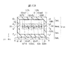
本発明者らが検討した比較例による加速度センサについて、図9〜図12を用いて説明する。図9は、比較例による加速度センサのメンブレン層の上面を示す平面図である。図10は、比較例による加速度センサのメンブレン層の下面を示す平面図である。図11および図12は、比較例による加速度センサの断面図である。 An acceleration sensor according to a comparative example studied by the present inventors will be described with reference to FIGS. FIG. 9 is a plan view showing the upper surface of the membrane layer of the acceleration sensor according to the comparative example. FIG. 10 is a plan view showing the lower surface of the membrane layer of the acceleration sensor according to the comparative example. 11 and 12 are cross-sectional views of an acceleration sensor according to a comparative example.
図9および図10に示すように、比較例による加速度センサR1では、機械的接合部32mが、平面視において1つの方向、すなわちx軸方向に沿って一直線に延在しており、絶縁物32Iの厚さは、例えば1.5μm〜2.0μm程度と薄い。このため、機械的接合部32mの機械的強度が低く、メンブレム32は、ハウジング(基板の貼合わせ)または実装などで生じる残留内部応力に起因して湾曲する。すなわち、固定部34T2と固定部34B2に生じる力は、図11または図12に示すように、メンブレン32を変形させ、検出電極の容量値のばらつきを増加させる虞がある。これにより、動作が不安定になり、さらに雑音が増加するので、高精度な加速度センサR1の実現は難しいと考えられた。
As shown in FIGS. 9 and 10, in the acceleration sensor R1 according to the comparative example, the mechanical joint 32m extends linearly in one direction, that is, in the x-axis direction in plan view. Is as thin as, for example, about 1.5 μm to 2.0 μm. For this reason, the mechanical strength of the mechanical joint 32m is low, and the
しかし、このような劣化は、本実施例1による加速度センサS1のように、機械的接合部32mを平面視においてx軸方向に非一直線とすることにより、改善することができる。 However, such deterioration can be improved by making the mechanical joint 32m non-linear in the x-axis direction in plan view as in the acceleration sensor S1 according to the first embodiment.
本実施例1による加速度センサS1は、図2〜図8に示すように、z軸の方向に変位可能なメンブレン32を備えており、メンブレン32は、x軸方向に延伸する機械的接合部32mを挟んで、y軸方向に互いに隣り合い、かつ、電気的に分離された第1可動部(可動部32TD,32TH)と第2可動部(可動部32BD,32BH)とを有する。さらに、機械的接合部32mは、第1箇所において、z軸方向に垂直なx軸方向またはy軸方向に対して第1角度を有する方向に延伸し、第1箇所とは異なる第2箇所において、z軸方向に垂直なx軸方向またはy軸方向に対して第1角度とは異なる第2角度を有する方向に延伸している。
As shown in FIGS. 2 to 8, the acceleration sensor S1 according to the first embodiment includes a
このように、機械的接合部32mを平面視においてx軸方向に非一直線とすることにより、機械的接合部32mの機械的強度を向上させて、ハウジングまたは実装などで生じる残留内部応力に起因したメンブレン32の湾曲を低減する。
As described above, by making the mechanical joint 32m non-linear in the x-axis direction in plan view, the mechanical strength of the mechanical joint 32m is improved, resulting in residual internal stress generated in the housing or mounting. The curvature of the
これにより、メンブレン32の変形を抑えることが可能になり、検出電極の容量値のばらつきを低減することができる。その結果、動作が安定して、雑音が低減するので、高精度な加速度センサS1を提供することができる。
This makes it possible to suppress the deformation of the
<本実施例1の変形例>
1.本実施例1の変形例1
本実施例1による加速度センサS1に備わる機械的接合部32mは、導電層32DLに設けられた1個の空隙32mAおよび導電層32HLに設けられた2個の空隙32mB,32mCを有している。
<Modification of First Embodiment>
1.
The mechanical joint 32m provided in the acceleration sensor S1 according to the first embodiment has one gap 32mA provided in the conductive layer 32DL and two gaps 32mB and 32mC provided in the conductive layer 32HL.
機械的接合部32mは、可変容量である可動部32TD,32BDの直流電気的なアイソレーションを持たせるためのものであり、導電層32HLに設けられる空隙は1個でもよい。しかし、交流電気的なアイソレーションを向上させるためには、導電層32DL,32HLの少なくとも一方の空隙を2個以上設置し、電気的に浮いた導電層(例えば導電物32mD)を1個以上設置することが望ましい。これにより、高精度な加速度センサの提供に繋がる。
The mechanical joining
2.本実施例1の変形例2および変形例3
本実施例1による加速度センサS1に備わる機械的接合部32mの平面視における形状は、図5および図6に示した形状に限定されるものではない。
2.
The shape in plan view of the mechanical joint 32m provided in the acceleration sensor S1 according to the first embodiment is not limited to the shapes shown in FIGS.
例えば図13および図14に示す変形例2による加速度センサS1vaのように、空隙32mA,32mB,32mCをx軸方向に延伸する部分とy軸方向に延伸する部分とを交互に接続した形状としてもよい。これにより、機械的接合部32mの平面視における形状は、x軸方向に延伸する部分とy軸方向に延伸する部分とを交互に接続した形状、所謂ミアンダ(meander)形状となり、機械的接合部32mの機械的強度が向上する。 For example, like the acceleration sensor S1va according to the second modification shown in FIGS. 13 and 14, the gaps 32mA, 32mB, and 32mC may be formed by alternately connecting portions extending in the x-axis direction and portions extending in the y-axis direction. Good. As a result, the shape of the mechanical joint 32m in a plan view becomes a so-called meander shape in which portions extending in the x-axis direction and portions extending in the y-axis direction are alternately connected. The mechanical strength of 32 m is improved.
また、空隙32mA,32mB,32mCのうち、少なくとも1個の空隙を平面視においてx軸方向に非一直線とし、他を一直線としてもよく、これにより、機械的接合部32mの機械的強度が向上する。
At least one of the
例えば図15および図16に示す変形例3による加速度センサS1vbのように、空隙32mA,32mBをx軸方向に延伸する部分とy軸方向に延伸する部分とを交互に接続した形状とし、空隙32mCをx軸方向に一直線に延伸する形状としてもよい。 For example, like the acceleration sensor S1vb according to the third modification shown in FIGS. 15 and 16, the gaps 32mA and 32mB are formed such that portions extending in the x-axis direction and portions extending in the y-axis direction are alternately connected to each other. May be stretched linearly in the x-axis direction.
3.本実施例1の変形例4
本変形例1による加速度センサS1では、機械的接合部32mはメンブレン32のx軸方向の一端から他端まで形成されており、x軸方向におけるメンブレン32の長さと機械的接合部32mの長さとは同じであるが、メンブレン32のx軸方向の一部分に機械的接合部32mを形成してもよい。
3. Modification Example 4 of
In the acceleration sensor S1 according to the first modification, the mechanical joint 32m is formed from one end to the other end in the x-axis direction of the
例えば図17A〜図18Bに示す変形例4による加速度センサS1vcのように、可動部32THと可動部BHとの間に、x軸方向にメンブレム32の長さよりも短い長さを有する機械的接合部32mを、x軸方向に1個または複数配置してもよい。加速度センサS1vcでは、2個の機械的接合部32mを例示している。機械的接合部32mを構成する導電物32mDL,32mDRは、y軸方向に長く、x軸方向に短い形状を有することができる。
For example, like the acceleration sensor S1vc according to the fourth modification shown in FIGS. 17A to 18B, a mechanical joint having a length shorter than the length of the
導電物32mDLは空隙32mFLで囲まれており、空隙32mFLは、可動部32THと導電物32mDLとを直流電気的に絶縁する絶縁体として機能し、可動部32BHと導電物32mDLとを直流電気的に絶縁する絶縁体として機能する。また、導電物32mDRは空隙32mFRで囲まれており、空隙32mFRは、可動部32THと導電物32mDRとを直流電気的に絶縁する絶縁体として機能し、可動部32BHと導電物32mDRとを直流電気的に絶縁する絶縁体として機能する。 The conductor 32mDL is surrounded by a gap 32mFL, and the gap 32mFL functions as an insulator that electrically insulates the movable portion 32TH and the conductor 32mDL, and electrically couples the movable portion 32BH and the conductor 32mDL. Functions as an insulating insulator. The conductor 32mDR is surrounded by a gap 32mFR. The gap 32mFR functions as an insulator that electrically insulates the movable portion 32TH and the conductor 32mDR, and connects the movable portion 32BH and the conductor 32mDR with each other. It functions as an insulator that electrically insulates.
さらに、可動部32TDの可動部32BDに対向する側面はx軸方向に沿って直線状に延在し、可動部32BDの可動部32TDに対向する側面はx軸方向に沿って直線状に延在している。そして、可動部32TDと可動部32BDとの間であって、導電物32mDL,32mDR直上には、絶縁物32Iを介して直線状の空隙32mEL,32mERが形成されている。 Further, a side surface of the movable portion 32TD facing the movable portion 32BD extends linearly along the x-axis direction, and a side surface of the movable portion 32BD facing the movable portion 32TD extends linearly along the x-axis direction. doing. Then, linear gaps 32mEL and 32mER are formed between the movable part 32TD and the movable part 32BD and directly above the conductors 32mDL and 32mDR via an insulator 32I.
直流電気的に浮いた導電物32mDL,32mDRをy軸方向に長く、x軸方向に短い形状とすることにより、機械的接合部32mの機械的強度が高くなる。さらに、導電物32mDL,32mDRと絶縁物32Iとの接触面積が小さくなるので、可変容量である可動部32TD,32BDの交流電気的なアイソレーションが向上する。 By making the conductors 32mDL and 32mDR floating in the direct current electrically long in the y-axis direction and short in the x-axis direction, the mechanical strength of the mechanical joint 32m is increased. Further, since the contact area between the conductors 32mDL and 32mDR and the insulator 32I is reduced, the AC electrical isolation of the movable portions 32TD and 32BD, which are variable capacitors, is improved.
このように、機械的接合部32mを平面視においてx軸方向に非一直線とし、複数の機械的接合部32mを設けることにより、メンブレン32の変形が抑えられるので、高精度な加速度センサの提供に繋がる。
In this way, by providing the mechanical joint 32m non-linearly in the x-axis direction in plan view and providing the plurality of
なお、可動部32TDと可動部32BDとの間および可動部32THと可動部32BHとの間であって、導電物32mDL,32mDR直上以外の部分は、絶縁物32Iは形成されておらず、機械的に接合されていないため、機械的接合部32mには該当しない。
In addition, between the movable part 32TD and the movable part 32BD and between the movable part 32TH and the movable part 32BH, except for the portions directly above the conductors 32mDL and 32mDR, the insulator 32I is not formed, and the mechanical It does not correspond to the mechanically joined
4.本実施例1の変形例5および変形例6
本実施例1による加速度センサS1は、4個の可変容量を有する。これらの可変容量は、例えば前記特許文献1の図1〜図3に記載されているように電気接続することで、高精度に加速度を検出することができる。
4. Modifications 5 and 6 of
The acceleration sensor S1 according to the first embodiment has four variable capacitors. These variable capacitors can detect acceleration with high accuracy by being electrically connected, for example, as described in FIGS. 1 to 3 of
例えば図19に示す変形例5による加速度センサS1vdのように、サーボ制御型加速度センサに適用する場合は、前述の実施例1の加速度センサS1に、DCサーボ用の固定電極12TL1,12TR1,12BL1,12BR1およびACサーボ用の固定電極12TL2,12TR2,12BL2,12BR2を付加すればよい。これにより、省電力および低雑音な加速度センサの提供に繋がる。 For example, when the present invention is applied to a servo control type acceleration sensor like the acceleration sensor S1vd according to the fifth modification shown in FIG. 19, the DC servo fixed electrodes 12TL1, 12TR1, 12BL1, 12BR1 and the fixed electrodes 12TL2, 12TR2, 12BL2, and 12BR2 for AC servo may be added. This leads to the provision of a power-saving and low-noise acceleration sensor.
また、例えば図20に示す変形例6による加速度センサS1veのように、機械的接合部32m(例えば図2参照)の片側に信号検出用の固定電極12TL,12TRを設置し、機械的接合部32m(例えば図2参照)を挟んで、固定電極12TL,12TRの反対側にDCサーボ用の固定電極12BL1,12BR1およびACサーボ用の固定電極12BL2,12BR2を設置してもよい。DCサーボ用の固定電極12BL1,12BR1およびACサーボ用の固定電極12BL2,12BR2に対向する可動部32BD(例えば図5参照)は、電気的に接地されている。 In addition, for example, like the acceleration sensor S1ve according to Modification 6 shown in FIG. 20, fixed electrodes 12TL and 12TR for signal detection are installed on one side of the mechanical joint 32m (see, for example, FIG. 2), and the mechanical joint 32m The fixed electrodes 12BL1 and 12BR1 for DC servo and the fixed electrodes 12BL2 and 12BR2 for AC servo may be provided on the opposite side of the fixed electrodes 12TL and 12TR with (see, for example, FIG. 2) interposed therebetween. The movable part 32BD (see FIG. 5, for example) facing the DC servo fixed electrodes 12BL1 and 12BR1 and the AC servo fixed electrodes 12BL2 and 12BR2 is electrically grounded.
これにより、DCサーボ用の固定電極12BL1,12BR1およびACサーボ用の固定電極12BL2,12BR2に流れるサーボ信号がチャージアンプに漏洩する量を抑えることができる。さらに、これに加えて、チャージアンプの入力端子からサーボ電極容量が見えないことによる実質信号検出用可変コンデンサの変化率が大きくなるため、いっそう、省電力および低雑音な加速度センサの提供に繋がる。 Thus, the amount of servo signals flowing through the fixed electrodes 12BL1 and 12BR1 for DC servo and the fixed electrodes 12BL2 and 12BR2 for AC servo can be suppressed from leaking to the charge amplifier. Further, in addition to this, the rate of change of the real signal detection variable capacitor due to the fact that the servo electrode capacitance cannot be seen from the input terminal of the charge amplifier increases, which leads to the provision of an acceleration sensor with even lower power consumption and lower noise.
本実施例2による加速度センサの構成について、前述の実施例1による加速度センサと異なる点を中心に、図面を参照しながら説明する。 The configuration of the acceleration sensor according to the second embodiment will be described with reference to the drawings, focusing on differences from the acceleration sensor according to the first embodiment.
<加速度センサの構成>
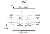
本実施例2による加速度センサの構成について、図21〜図23を参照しながら説明する。図21は、本実施例2による加速度センサのメンブレン層の上面を示す平面図である(前述の実施例1による加速度センサS1の説明に使用した図5に相当する。)。図22は、本実施例2による加速度センサのメンブレン層の下面を示す平面図である(前述の実施例1による加速度センサS1の説明に使用した図6に相当する。)。図23は、本実施例2による加速度センサのキャップ層の下面を示す平面図である(前述の実施例1による加速度センサS1の説明に使用した図7に相当する。)。
<Configuration of acceleration sensor>
The configuration of the acceleration sensor according to the second embodiment will be described with reference to FIGS. FIG. 21 is a plan view showing the upper surface of the membrane layer of the acceleration sensor according to the second embodiment (corresponding to FIG. 5 used for describing the acceleration sensor S1 according to the first embodiment described above). FIG. 22 is a plan view showing the lower surface of the membrane layer of the acceleration sensor according to the second embodiment (corresponding to FIG. 6 used for describing the acceleration sensor S1 according to the first embodiment described above). FIG. 23 is a plan view showing the lower surface of the cap layer of the acceleration sensor according to the second embodiment (corresponding to FIG. 7 used for describing the acceleration sensor S1 according to the first embodiment described above).
図21および図22に示すように、本実施例2による加速度センサS2を構成する機械的接合部32mの形状は、前述の実施例1の変形例4による加速度センサS1vcを構成する機械的接合部32mの形状と同じである。しかし、本実施例2による加速度センサS2では、機械的接合部32mが2列(4個)設置されており、メンブレン32が直流電気的に3個に分割されている。すなわち、3個の可動部(可動電極)32TD,32CD,32BDが配置されている。
As shown in FIGS. 21 and 22, the shape of the mechanical joint 32m constituting the acceleration sensor S2 according to the second embodiment is the same as that of the mechanical joint constituting the acceleration sensor S1vc according to the fourth modification of the first embodiment. It is the same as the shape of 32 m. However, in the acceleration sensor S2 according to the second embodiment, the
従って、可動部32THと可動部32CHとの間には、導電物32mDLTが空隙32mFLTに囲まれて配置され、導電物32mDRTが空隙32mFRTに囲まれて配置されている。また、可動部32CHと可動部32BHとの間には、導電物32mDLBが空隙32mFLBに囲まれて配置され、導電物32mDRBが空隙32mFRBに囲まれて配置されている。 Therefore, between the movable part 32TH and the movable part 32CH, the conductor 32mDLT is arranged surrounded by the gap 32mFLT, and the conductor 32mDRT is arranged surrounded by the gap 32mFRT. In addition, between the movable portion 32CH and the movable portion 32BH, a conductor 32mDLB is arranged surrounded by a gap 32mFLB, and a conductor 32mDRB is arranged surrounded by a gap 32mFRB.
図23に示すように、固定電極12TL,12TR,12BL,12BRに加えて、加速度センサS2では、サーボ制御用の固定電極12TL3,12TR3,12BL3,12BR3,12L4,12R4が設置されている。固定電極12TL,12TRに対向する可動部32TDと、固定電極12BL,12BRに対向する可動部32BDと、サーボ制御用の固定電極12TL3,12TR3,12BL3,12BR3,12L4,12R4に対向する可動部32CDは、機械的接合部32mで互いに直流電気的には絶縁され、機械的には接続されている。 As shown in FIG. 23, in addition to the fixed electrodes 12TL, 12TR, 12BL, and 12BR, the acceleration sensor S2 includes servo control fixed electrodes 12TL3, 12TR3, 12BL3, 12BR3, 12L4, and 12R4. The movable part 32TD facing the fixed electrodes 12TL and 12TR, the movable part 32BD facing the fixed electrodes 12BL and 12BR, and the movable part 32CD facing the fixed electrodes 12TL3, 12TR3, 12BL3, 12BR3, 12L4, and 12R4 for servo control. Are electrically insulated and mechanically connected to each other at the mechanical joint 32m.
また、サーボ制御用の固定電極12TL3,12BL3は電気的に接続されている。さらに、サーボ制御用の固定電極12TR3,12BR3は電気的に接続されている。これらは、加速度センサS2のx軸方向に対して対称に配置され(紙面右側と紙面左側)、互いに分割されているが、電気的に接続されて一つの固定電極として機能している。これらは、前記特許文献1の図1に示すDCサーボ制御用容量対の右固定電極およびDCサーボ制御用容量対の左固定電極として機能する。 The fixed electrodes 12TL3 and 12BL3 for servo control are electrically connected. Further, the fixed electrodes 12TR3 and 12BR3 for servo control are electrically connected. These are arranged symmetrically with respect to the x-axis direction of the acceleration sensor S2 (on the right side of the paper and on the left side of the paper), and are divided from each other, but are electrically connected and function as one fixed electrode. These function as the right fixed electrode of the DC servo control capacitor pair and the left fixed electrode of the DC servo control capacitor pair shown in FIG.
また、サーボ制御用の固定電極12TL3,12TR3,12BL3,12BR3,12L4,12R4に対向する可動部32CDは電気的に接地されている。 The movable portion 32CD facing the servo control fixed electrodes 12TL3, 12TR3, 12BL3, 12BR3, 12L4, and 12R4 is electrically grounded.
図では省略しているが、加速度センサS2では、前述の実施例1による加速度センサS1と同様に、可動部32TDは、可動部32THと直流電気的に接続されている。また、可動部32BDは、可動部32BHと直流電気的に接続されている。さらに、加速度センサS2では、可動部32CDは、可動部32CHと直流電気的に接続されている。これにより、可動電極の電気抵抗を下げることができる。 Although omitted in the figure, in the acceleration sensor S2, the movable portion 32TD is DC-electrically connected to the movable portion 32TH, similarly to the acceleration sensor S1 according to the first embodiment described above. Further, the movable part 32BD is DC-electrically connected to the movable part 32BH. Further, in the acceleration sensor S2, the movable section 32CD is DC-electrically connected to the movable section 32CH. Thereby, the electric resistance of the movable electrode can be reduced.
また、導電物32mDLT,32mDRT,32mDLB,32mDRBは、直流電気的に浮いている。これにより、可動部32TDと可動部32BDとの間の交流電気的なアイソレーションが向上する。 In addition, the conductors 32mDLT, 32mDRT, 32mDLB, and 32mDRB float in direct current. Thereby, AC electrical isolation between the movable part 32TD and the movable part 32BD is improved.
このように、本実施例2による加速度センサS2は、機械的接合部32mが平面視においてx軸方向に非一直線であるため、機械的接合部32mが2列(4個)設置されているにもかかわらず、前述の実施例1による加速度センサS1と同様に、容量値のばらつきを低減することができる。これにより、動作が安定して、雑音が低減するので、高精度な加速度センサS2を提供することができる。さらに、省電力および低雑音な加速度センサS2の提供に繋がる。
As described above, in the acceleration sensor S2 according to the second embodiment, since the
<本実施例2の変形例>
本実施例2による加速度センサS2では、固定電極12TL,12TR,12BL,12BRに対向するように、機械的接合部32mを配置したが、機械的接合部32mの配置は、これに限定されるものではない。
<Modification of Second Embodiment>
In the acceleration sensor S2 according to the second embodiment, the mechanical joint 32m is arranged to face the fixed electrodes 12TL, 12TR, 12BL, and 12BR, but the arrangement of the mechanical joint 32m is not limited to this. is not.
例えば図24および図25に示す変形例による加速度センサS2vのように、キャップ層CapLとメンブレン層MemLとを上面から重ねて見たときに(例えば図2参照)、固定電極12TL,12TRおよび固定電極12BL,12BRをそれぞれ囲むように、2個の機械的接合部32mを配置してもよい。
For example, when the cap layer CapL and the membrane layer MemL are viewed from above (for example, see FIG. 2), as in the acceleration sensor S2v according to the modification shown in FIGS. 24 and 25, the fixed electrodes 12TL and 12TR and the fixed electrode Two
具体的には、一方の機械的接合部32mは、x軸方向に延伸する部分と、x軸方向に延伸する部分の一端からメンブレン32の一方の外側(紙面左側)に向かってy軸方向に延伸する部分とからなり、互いに離間して配置されたL字型の2つの空隙32mBTおよび空隙32mCT、並びに空隙32mBTと空隙32mCTとの間に挟まれた導電物32mDLT,32mDRTを含む。他方の機械的接合部32mは、x軸方向に延伸する部分と、x軸方向に延伸する部分の一端からメンブレン32の他方の外側(紙面右側)に向かってy軸方向に延伸する部分とからなり、互いに離間して配置されたL字型の2つの空隙32mBBおよび空隙32mCB、並びに空隙32mBBと空隙32mCBとの間に挟まれた導電物32mDLB,32mDRBを含む。
Specifically, one mechanical joining
導電物32mDLT,32mDRT直上には、絶縁物32I(例えば図2参照)を介して空隙32mALT,32mARTが形成され、導電物32mDLB,32mDRB直上には、絶縁物32I(例えば図2参照)を介して空隙32mALB,32mARBが形成されている。 Air gaps 32mALT and 32mART are formed directly above the conductors 32mDLT and 32mDRT via an insulator 32I (for example, see FIG. 2), and directly above the conductors 32mDLB and 32mDRB via an insulator 32I (for example, see FIG. 2). Gaps 32mALB and 32mARB are formed.
このように、本実施例2の変形例による加速度センサS2vでも、機械的接合部32mが平面視においてx軸方向に非一直線であるため、機械的接合部32mが2個設置されているにもかかわらず、前述の実施例2による加速度センサS2と同様の効果がある。さらに、チャージアンプの入力端子に接続される固定電極12TL,12TR,12BL,12BRに対向する可動部32TD,32BDの面積が小さくなり、可動部32TD,32BDの対地寄生容量を削減することができるので、さらに、低雑音な加速度センサの提供に繋がる。
As described above, also in the acceleration sensor S2v according to the modification of the second embodiment, since the mechanical joint 32m is non-linear in the x-axis direction in a plan view, even if two
本実施例3による加速度センサの構成について、前述の実施例2による加速度センサと異なる点を中心に、図面を参照しながら説明する。 The configuration of the acceleration sensor according to the third embodiment will be described with reference to the drawings, focusing on differences from the acceleration sensor according to the second embodiment.
<加速度センサの構成>
本実施例3による加速度センサの構成について、図26〜図28を参照しながら説明する。図26は、本実施例3による加速度センサのメンブレン層の上面を示す平面図である(前述の実施例2による加速度センサS2の説明に使用した図21に相当する。)。図27は、本実施例3による加速度センサのメンブレン層の下面を示す平面図である(前述の実施例2による加速度センサS2の説明に使用した図22に相当する。)。図28は、本実施例3による加速度センサのキャップ層の下面を示す平面図である(前述の実施例2による加速度センサS2の説明に使用した図23に相当する。)。
<Configuration of acceleration sensor>
The configuration of the acceleration sensor according to the third embodiment will be described with reference to FIGS. FIG. 26 is a plan view showing the upper surface of the membrane layer of the acceleration sensor according to the third embodiment (corresponding to FIG. 21 used for describing the acceleration sensor S2 according to the second embodiment described above). FIG. 27 is a plan view showing the lower surface of the membrane layer of the acceleration sensor according to the third embodiment (corresponding to FIG. 22 used for describing the acceleration sensor S2 according to the second embodiment described above). FIG. 28 is a plan view showing the lower surface of the cap layer of the acceleration sensor according to the third embodiment (corresponding to FIG. 23 used for describing the acceleration sensor S2 according to the second embodiment described above).
本実施例3による加速度センサS3の機械的接合部32mの形状および数は、前述の実施例2による加速度センサS2の機械的接合部32mの形状および数とそれぞれ同じである。しかし、本実施例3による加速度センサS3では、前述の実施例2による加速度センサS2の可動部32CDが、可動部32CTDと32CBDに分割され、前述の実施例2による加速度センサS2の可動部32CHが、可動部32CTHと32CBHに分割されている。そして、導電層32HL(例えば図2参照)で形成されたたわみバネ36L,36Rによって、可動部32CTD,32CTHと可動部32CBD,32CBHとが機械的かつ直流電気的に接続されている。
The shape and number of the mechanical joint 32m of the acceleration sensor S3 according to the third embodiment are the same as the shape and number of the mechanical joint 32m of the acceleration sensor S2 according to the second embodiment. However, in the acceleration sensor S3 according to the third embodiment, the movable part 32CD of the acceleration sensor S2 according to the second embodiment is divided into the movable parts 32CTD and 32CBD, and the movable part 32CH of the acceleration sensor S2 according to the second embodiment is used. , The movable portion 32CTH and 32CBH. The movable portions 32CTD, 32CTH and the movable portions 32CBD, 32CBH are mechanically and DC-electrically connected to each other by the
図では省略しているが、加速度センサS3では、前述の実施例2による加速度センサS2と同様に、可動部32TDは、可動部32THと直流電気的に接続されている。また、可動部32BDは、可動部32BHと直流電気的に接続されている。さらに、加速度センサS3では、可動部32CTDは、可動部32CTHと直流電気的に接続されている。同様に、可動部32CBDは、可動部32CBHと直流電気的に接続されている。これにより、可動電極の電気抵抗を下げることができる。 Although omitted in the drawing, in the acceleration sensor S3, the movable portion 32TD is DC-electrically connected to the movable portion 32TH, similarly to the acceleration sensor S2 according to the second embodiment described above. Further, the movable part 32BD is DC-electrically connected to the movable part 32BH. Further, in the acceleration sensor S3, the movable part 32CTD is DC-electrically connected to the movable part 32CTH. Similarly, the movable part 32CBD is DC-electrically connected to the movable part 32CBH. Thereby, the electric resistance of the movable electrode can be reduced.
また、導電物32mDLT,32mDRT,32mDLB,32mDRBは、直流電気的に浮いている。これにより、可動部32TDと可動部32CTDとの間および可動部32CBDと可動部32BDとの間の交流電気的なアイソレーションが向上する。 In addition, the conductors 32mDLT, 32mDRT, 32mDLB, and 32mDRB float in direct current. Thereby, AC electrical isolation between the movable part 32TD and the movable part 32CTD and between the movable part 32CBD and the movable part 32BD are improved.
たわみバネ36L,36Rは、xy平面内では薄く、z軸方向には厚い板の形状をなしており、xy平面内で所謂ミアンダ形状をなしている。そのため、たわみバネ36L,36Rで機械的に接続された可動部32CTDと可動部32CBDとは、z軸方向には一体化、y軸方向には相対的に動くことができる。これにより、キャップ層CapL、ベース層BasLおよび実装基板層SubLが固定部34T2および34B2を介して(例えば図2参照)、メンブレン32に与える力が開放される。
The flexure springs 36L, 36R have a thin plate shape in the xy plane and a thick plate shape in the z-axis direction, and have a so-called meander shape in the xy plane. Therefore, the movable part 32CTD and the movable part 32CBD mechanically connected by the
たわみバネ36L,36Rは、導電層32HL(例えば図2参照)で形成されているため、可動部32CTD,32CTH、たわみバネ36L,36Rおよび可動部32CBD,32CBHは直流電気的に接続されている。 Since the flexure springs 36L and 36R are formed by the conductive layer 32HL (see, for example, FIG. 2), the movable portions 32CTD and 32CTH, the flexure springs 36L and 36R, and the movable portions 32CBD and 32CBH are DC-electrically connected.
このように、本実施例3による加速度センサS3は、機械的接合部32mが平面視においてx軸方向に非一直線であるため、前述の実施例2による加速度センサS2と同様に、機械的接合部32mの折れ曲りを減少させることができるため、容量値のばらつきを低減することができる。さらに、たわみバネ36L,36Rがメンブレン32に与える変形力を開放するため、さらに、容量値のばらつきを低減することができる。これにより、動作が安定して、雑音が低減するので、高精度な加速度センサS3を提供することができる。さらに、省電力および低雑音な加速度センサS3の提供に繋がる。
As described above, in the acceleration sensor S3 according to the third embodiment, since the mechanical joint 32m is non-linear in the x-axis direction in plan view, the mechanical joint 32m is similar to the acceleration sensor S2 according to the second embodiment. Since the bending of 32 m can be reduced, the variation in the capacitance value can be reduced. Further, since the bending springs 36L and 36R release the deformation force applied to the
<本実施例3の変形例>
前述の実施例3による加速度センサS3では、可動部32CTD,32CTHと、可動部32CBD,32CBHとの間に、たわみバネ36L,36Rを配置したが、たわみバネ36L,36Rの配置は、これに限定されるものではない。
<Modification of Third Embodiment>
In the acceleration sensor S3 according to the third embodiment, the flexure springs 36L and 36R are arranged between the movable portions 32CTD and 32CTH and the movable portions 32CBD and 32CBH, but the arrangement of the flexure springs 36L and 36R is not limited to this. It is not something to be done.
1.本実施例3の変形例1
例えば図29および図30に示す変形例1による加速度センサS3vのように、ねじれバネ33T2,33B2の根元にたわみバネ37T,37Bを配置してもよい。
1.
For example, like the acceleration sensor S3v according to the first modification shown in FIGS. 29 and 30, the bending springs 37T and 37B may be arranged at the roots of the torsion springs 33T2 and 33B2.
たわみバネ37T,37Bは、xy平面内では薄く、z軸方向には厚い板の形状をなしており、ねじれバネ33T2,33B2と直交したx軸方向に長く形成されている。また、たわみバネ37Tのx軸方向の両端は可動部32THに接続され、かつ、たわみバネ37Tのx軸方向のほぼ中央部にねじれバネ33T2が機械的に接続されている。同様に、たわみバネ37Bのx軸方向の両端は可動部32BHに接続され、かつ、たわみバネ37Bのx軸方向のほぼ中央部にねじれバネ33B2が機械的に接続されている。
The flexure springs 37T and 37B have a thin plate shape in the xy plane and a thick plate shape in the z-axis direction, and are formed long in the x-axis direction orthogonal to the torsion springs 33T2 and 33B2. Further, both ends in the x-axis direction of the
そのため、たわみバネ37Tで機械的に接続された可動部32TDとねじれバネ33T2とは、y軸方向およびz軸方向には一体化、x軸方向には相対的に動くことができる。同様に、たわみバネ37Bで機械的に接続された可動部32BDとねじれバネ33B2とは、y軸方向およびz軸方向には一体化、x軸方向には相対的に動くことができる。これにより、キャップ層CapL、ベース層BasLおよび実装基板層SubLがねじれバネ33T2,33B2を介して(例えば図2参照)、メンブレン32に与える力が開放される。
Therefore, the movable portion 32TD and the torsion spring 33T2 mechanically connected by the
2.本実施例3の変形例2
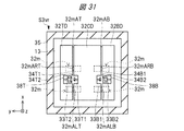
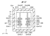
また、例えば図31および図32に示す変形例2による加速度センサS3vrのように、ねじれバネ33T2,33B2の根元にたわみバネ38T,38Bを配置してもよい。
2.
Further, for example, like the acceleration sensor S3vr according to the
たわみバネ38T,38Bは、xy平面内では薄く、z軸方向には厚い板の形状をなしており、ねじれバネ33T2,33B2と直交したx軸方向に長く形成されている。また、たわみバネ38Tのx軸方向の両端は固定部34T2に接続され、かつ、たわみバネ38Tのx軸方向のほぼ中央部にねじれバネ33T2が機械的に接続されている。同様に、たわみバネ38Bのx軸方向の両端は固定部34B2に接続され、かつ、たわみバネ38Bのx軸方向のほぼ中央部にねじれバネ33B2が機械的に接続されている。
The flexure springs 38T and 38B have a thin plate shape in the xy plane and a thick plate shape in the z-axis direction, and are formed long in the x-axis direction orthogonal to the torsion springs 33T2 and 33B2. Further, both ends in the x-axis direction of the
そのため、たわみバネ38Tで機械的に接続された固定部34T2とねじれバネ33T2とは、y軸方向およびz軸方向には一体化、x軸方向には相対的に動くことができる。同様に、たわみバネ38Bで機械的に接続された固定部34B2とねじれバネ33B2とは、y軸方向およびz軸方向には一体化、x軸方向には相対的に動くことができる。これにより、キャップ層CapL、ベース層BasLおよび実装基板層SubLがねじれバネ33T2,33B2を介して(例えば図2参照)、メンブレン32に与える力が開放される。
Therefore, the fixed portion 34T2 and the torsion spring 33T2 mechanically connected by the
このように、本実施例3の変形例1による加速度センサS3vおよび本実施例3の変形例2による加速度センサS3vrにおいても、本実施例3による加速度センサS3とほぼ同様の効果が得られる。 As described above, the acceleration sensor S3v according to the first modification of the third embodiment and the acceleration sensor S3vr according to the second modification of the third embodiment have substantially the same effects as the acceleration sensor S3 according to the third embodiment.
以上、本発明者によってなされた発明を実施の形態に基づき具体的に説明したが、本発明は前記実施の形態に限定されるものではなく、その要旨を逸脱しない範囲で種々変更可能であることはいうまでもない。 As described above, the invention made by the inventor has been specifically described based on the embodiment. However, the present invention is not limited to the embodiment, and various modifications can be made without departing from the gist of the invention. Needless to say.
11 絶縁物
12BL,12BR,12TL,12TR 固定電極
12BL1,12BR1,12TL1,12TR1 DCサーボ用の固定電極
12BL2,12BR2,12TL2,12TR2 ACサーボ用の固定電極
12BL3,12BR3,12TL3,12TR3 サーボ制御用の固定電極
12L4,12R4 サーボ制御用の固定電極
13 空洞
21 絶縁物
32 メンブレン(質量体)
32BD,32BH 可動部
32CBD,32CBH 可動部
32CD,32CH 可動部
32CTD,32CTH 可動部
32DL 導電層
32HL 導電層
32I 絶縁物
32TD,32TH 可動部
32m 機械的接合部
32mA 空隙
32mB,32mBB,32mBT 空隙
32mC,32mCB,32mCT 空隙
32mD 導電物
32mDL,32mDLB,32mDLT 導電物
32mDR,32mDRB,32mDRT 導電物
32mEL,32mER 空隙
32mFL,32mFLB,32mFLT 空隙
32mFR,32mFRB,32mFRT 空隙
32viaB,32viaT 導電物
33B1,33B2,33T1,33T2 ねじれバネ
34B1,34B2,34T1,34T2 固定部
35 側部
36L,36R たわみバネ
37B,37T たわみバネ
38B,38T たわみバネ
41 絶縁物
42 接着剤
BasL ベース層
CapL キャップ層
G1 起振源
G2a,G2b,G2c,G2d,G2e 受振器
G3 地表
G4a,G4b 地層の境界
MemL メンブレン層
S1,S1va,S1vb,S1vc,S1vd,S1ve 加速度センサ
S2,S2v 加速度センサ
S3,S3v,S3vr 加速度センサ
SubL 実装基板層
11 Insulators 12BL, 12BR, 12TL, 12TR Fixed electrodes 12BL1, 12BR1, 12TL1, 12TR1 DC servo fixed electrodes 12BL2, 12BR2, 12TL2, 12TR2 AC servo fixed electrodes 12BL3, 12BR3, 12TL3, 12TR3 Servo control fixed Electrodes 12L4, 12R4 Fixed
32BD, 32BH movable part 32CBD, 32CBH movable part 32CD, 32CH movable part 32CTD, 32CTH movable part 32DL conductive layer 32HL conductive layer 32I insulator 32TD, 32TH
Claims (15)
前記第1基板から第1方向に離間して設けられた第2基板と、
前記第1基板と前記第2基板との間に設けられ、前記第1方向に変位可能な質量体と、
を備え、
前記質量体は、
第1可動部と、
前記第1可動部と電気的に分離された第2可動部と、
前記第1可動部と前記第2可動部とを前記第1方向と直交する第2方向に機械的に接続する第1機械的接合部と、
を有し、
前記第1機械的接合部は、前記第1方向と直交する平面において、前記第2方向に対して第1角度を有する方向に延伸する第1部分と、前記第2方向に対して前記第1角度と異なる第2角度を有する方向に延伸する第2部分と、を有している、加速度センサ。 A first substrate;
A second substrate provided apart from the first substrate in a first direction;
A mass body provided between the first substrate and the second substrate and displaceable in the first direction;
With
The mass body is
A first movable part;
A second movable unit electrically separated from the first movable unit;
A first mechanical joint that mechanically connects the first movable part and the second movable part in a second direction orthogonal to the first direction;
Has,
A first portion extending in a direction having a first angle with respect to the second direction in a plane perpendicular to the first direction; and a first portion extending in a direction having a first angle with respect to the second direction. A second portion extending in a direction having a second angle different from the angle.
前記第1可動部、前記第2可動部および前記第1機械的接合部のそれぞれは、
絶縁物と、
前記絶縁物の第1面に形成された第1導電層と、
前記絶縁物の前記第1面とは反対側の第2面に形成された第2導電層と、
から構成され、
前記第1機械的接合部の前記第1導電層に形成された第1空隙で、前記第1可動部を構成する前記第1導電層と、前記第2可動部を構成する前記第1導電層とは分離され、
前記第1空隙下に前記第1機械的接合部を構成する前記第2導電層が設けられ、
前記第1可動部を構成する前記第2導電層と、前記第1機械的接合部を構成する前記第2導電層とは第2空隙で分離され、
前記第2可動部を構成する前記第2導電層と、前記第1機械的接合部を構成する前記第2導電層とは第3空隙で分離されている、加速度センサ。 The acceleration sensor according to claim 1,
Each of the first movable portion, the second movable portion, and the first mechanical joint,
Insulation and
A first conductive layer formed on a first surface of the insulator;
A second conductive layer formed on a second surface of the insulator opposite to the first surface;
Composed of
A first gap formed in the first conductive layer of the first mechanical joint, the first conductive layer forming the first movable portion, and the first conductive layer forming the second movable portion; Is separated from
The second conductive layer constituting the first mechanical joint is provided below the first gap,
The second conductive layer forming the first movable portion and the second conductive layer forming the first mechanical joint are separated by a second gap,
An acceleration sensor, wherein the second conductive layer forming the second movable section and the second conductive layer forming the first mechanical joint are separated by a third gap.
前記第1機械的接合部を構成する前記第2導電層は、直流電気的に浮いている、加速度センサ。 The acceleration sensor according to claim 2,
The acceleration sensor, wherein the second conductive layer forming the first mechanical joint is DC-electrically floating.
断面視において、前記第1空隙下に前記第2導電層が形成され、前記第2空隙上および前記第3空隙上に前記第1導電層が形成されている、加速度センサ。 The acceleration sensor according to claim 2,
In a cross-sectional view, an acceleration sensor in which the second conductive layer is formed below the first gap, and the first conductive layer is formed on the second gap and the third gap.
前記第1空隙と前記第2導電層との間の前記絶縁物は除去され、前記第2空隙と前記第1導電層との間および前記第3空隙と前記第1導電層との間の前記絶縁物は除去されている、加速度センサ。 The acceleration sensor according to claim 4,
The insulator between the first gap and the second conductive layer is removed, and the insulator between the second gap and the first conductive layer and between the third gap and the first conductive layer are removed. Accelerometer with insulation removed.
前記第1部分における前記第1機械的接合部は、前記第2方向に延伸し、前記第2部分における前記第1機械的接合部は、前記第1方向と前記第2方向とに直交する第3方向に延伸する、加速度センサ。 The acceleration sensor according to claim 1,
The first mechanical joint in the first part extends in the second direction, and the first mechanical joint in the second part is perpendicular to the first direction and the second direction. An acceleration sensor that extends in three directions.
前記第1方向と直交する平面において、前記第1機械的接合部はミアンダ形状をなしている、加速度センサ。 The acceleration sensor according to claim 6,
The acceleration sensor, wherein the first mechanical joint has a meandering shape in a plane orthogonal to the first direction.
前記質量体は、
前記第1可動部および前記第2可動部と電気的に分離された第3可動部と、
前記第2可動部と前記第3可動部とを前記第2方向に機械的に接続する第2機械的接合部と、
をさらに有し、
前記第2機械的接合部は、前記第1方向と直交する平面において、前記第2方向に対して第3角度を有する方向に延伸する第3部分と、前記第2方向に対して前記第3角度と異なる第4角度を有する方向に延伸する第4部分と、を有している、加速度センサ。 The acceleration sensor according to claim 1,
The mass body is
A third movable portion electrically separated from the first movable portion and the second movable portion,
A second mechanical joint that mechanically connects the second movable part and the third movable part in the second direction;
Further having
A second portion extending in a direction having a third angle with respect to the second direction in a plane orthogonal to the first direction; and a third portion extending in a direction having a third angle with respect to the second direction. A fourth portion extending in a direction having a fourth angle different from the angle.
前記第1基板から第1方向に離間して設けられた第2基板と、
前記第1基板と前記第2基板との間に設けられ、前記第1方向に変位可能な質量体と、
を備え、
前記質量体は、
第1可動部と、
前記第1可動部と電気的に分離された第2可動部と、
前記第1可動部と前記第2可動部とを前記第1方向と直交する第2方向に機械的に接続する第1機械的接合部と、
を有し、
前記第1機械的接合部の前記第1方向と前記第2方向とに直交する第3方向の長さが、前記第1可動部および前記第2可動部の前記第3方向の長さよりも短く、
前記第1可動部、前記第2可動部および前記第1機械的接合部のそれぞれは、
絶縁物と、
前記絶縁物の第1面に形成された第1導電層と、
前記絶縁物の前記第1面とは反対側の第2面に形成された第2導電層と、
から構成され、
前記第1機械的接合部の前記第1導電層に形成された第1空隙で、前記第1可動部を構成する前記第1導電層と、前記第2可動部を構成する前記第1導電層とは分離され、
前記第1空隙下に前記第1機械的接合部を構成する前記第2導電層が設けられ、
前記第1可動部を構成する前記第2導電層と、前記第1機械的接合部を構成する前記第2導電層とは第2空隙で分離され、
前記第2可動部を構成する前記第2導電層と、前記第1機械的接合部を構成する前記第2導電層とは第3空隙で分離されている、加速度センサ。 A first substrate;
A second substrate provided apart from the first substrate in a first direction;
A mass body provided between the first substrate and the second substrate and displaceable in the first direction;
With
The mass body is
A first movable part;
A second movable unit electrically separated from the first movable unit;
A first mechanical joint that mechanically connects the first movable part and the second movable part in a second direction orthogonal to the first direction;
Has,
A length of the first mechanical joint in a third direction orthogonal to the first direction and the second direction is shorter than a length of the first movable portion and the second movable portion in the third direction. ,
Each of the first movable portion, the second movable portion, and the first mechanical joint,
Insulation and
A first conductive layer formed on a first surface of the insulator;
A second conductive layer formed on a second surface of the insulator opposite to the first surface;
Composed of
A first gap formed in the first conductive layer of the first mechanical joint, the first conductive layer forming the first movable section, and the first conductive layer forming the second movable section; Is separated from
The second conductive layer constituting the first mechanical joint is provided below the first gap,
The second conductive layer forming the first movable portion and the second conductive layer forming the first mechanical joint are separated by a second gap,
An acceleration sensor, wherein the second conductive layer forming the second movable portion and the second conductive layer forming the first mechanical joint are separated by a third gap.
断面視において、前記第1空隙下に前記第2導電層が形成され、前記第2空隙上および前記第3空隙上に前記第1導電層が形成されている、加速度センサ。 The acceleration sensor according to claim 9,
In a cross-sectional view, an acceleration sensor in which the second conductive layer is formed below the first gap, and the first conductive layer is formed on the second gap and the third gap.
前記第1機械的接合部を構成する前記第2導電層の前記第3方向の長さは、前記第1機械的接合部を構成する前記第2導電層の前記第2方向の長さよりも短く、前記第2空隙および前記第3空隙は、前記第1機械的接合部を構成する前記第2導電層の周囲に形成されている、加速度センサ。 The acceleration sensor according to claim 9,
The length in the third direction of the second conductive layer that forms the first mechanical joint is shorter than the length of the second conductive layer that forms the first mechanical joint in the second direction. The acceleration sensor, wherein the second gap and the third gap are formed around the second conductive layer forming the first mechanical joint.
前記質量体は、
前記第1可動部および前記第2可動部と電気的に分離された第3可動部と、
前記第2可動部と前記第3可動部とを前記第2方向に機械的に接続する第2機械的接合部と、
をさらに有し、
前記第2機械的接合部の前記第3方向の長さが、前記第2可動部および前記第3可動部の前記第3方向の長さよりも短く、
前記第3可動部および前記第2機械的接合部のそれぞれは、
前記絶縁物と、
前記第1導電層と、
前記第2導電層と、
から構成され、
前記第2機械的接合部の前記第1導電層に形成された第4空隙で、前記第2可動部を構成する前記第1導電層と、前記第3可動部を構成する前記第1導電層とは分離され、
前記第4空隙下に前記第2機械的接合部を構成する前記第2導電層が設けられ、
前記第2可動部を構成する前記第2導電層と、前記第2機械的接合部を構成する前記第2導電層とは第5空隙で分離され、
前記第3可動部を構成する前記第2導電層と、前記第2機械的接合部を構成する前記第2導電層とは第6空隙で分離されている、加速度センサ。 The acceleration sensor according to claim 9,
The mass body is
A third movable portion electrically separated from the first movable portion and the second movable portion,
A second mechanical joint that mechanically connects the second movable part and the third movable part in the second direction;
Further having
The length of the second mechanical joint in the third direction is shorter than the length of the second movable part and the third movable part in the third direction,
Each of the third movable part and the second mechanical joint is
Said insulator;
Said first conductive layer;
Said second conductive layer;
Composed of
A fourth gap formed in the first conductive layer of the second mechanical joint, the first conductive layer forming the second movable portion, and the first conductive layer forming the third movable portion; Is separated from
The second conductive layer constituting the second mechanical joint is provided below the fourth gap,
The second conductive layer forming the second movable portion and the second conductive layer forming the second mechanical joint are separated by a fifth gap,
An acceleration sensor, wherein the second conductive layer forming the third movable portion and the second conductive layer forming the second mechanical joint are separated by a sixth gap.
前記第2可動部を構成する前記第1導電層、前記絶縁物および前記第2導電層は、前記第3方向に延伸する分離部で第1分離可動部と、第2分離可動部とに分離され、
前記第1分離可動部と前記第2分離可動部とは、前記第2導電層からなる第1バネにより接続されている、加速度センサ。 The acceleration sensor according to claim 12,
The first conductive layer, the insulator and the second conductive layer constituting the second movable section are separated into a first separation movable section and a second separation movable section by a separation section extending in the third direction. And
An acceleration sensor, wherein the first separation movable part and the second separation movable part are connected by a first spring made of the second conductive layer.
一端が前記第1可動部を固定する第1固定部に接続され、前記第2導電層からなる前記第2方向に延伸する第2バネと、
前記第2バネの他端と前記第1可動部とに接続され、前記第2導電層からなる前記第3方向に延伸する第3バネと、
一端が前記第2可動部を固定する第2固定部に接続され、他端が前記第2可動部に接続され、前記第2導電層からなる前記第2方向に延伸する第4バネと、
一端が前記第3可動部を固定する第3固定部に接続され、前記第2導電層からなる前記第2方向に延伸する第5バネと、
前記第5バネの他端と前記第3可動部とに接続され、前記第2導電層からなる前記第3方向に延伸する第6バネと、
一端が前記第2可動部を固定する第4固定部に接続され、他端が前記第2可動部に接続され、前記第2導電層からなる前記第2方向に延伸する第7バネと、
をさらに有する、加速度センサ。 The acceleration sensor according to claim 12,
A second spring having one end connected to a first fixing portion for fixing the first movable portion, and extending in the second direction and including the second conductive layer;
A third spring connected to the other end of the second spring and the first movable portion and extending in the third direction and including the second conductive layer;
A fourth spring having one end connected to a second fixing portion for fixing the second movable portion, the other end connected to the second movable portion, and extending in the second direction made of the second conductive layer;
A fifth spring having one end connected to a third fixing portion fixing the third movable portion and extending in the second direction, the fifth spring being made of the second conductive layer;
A sixth spring connected to the other end of the fifth spring and the third movable portion and extending in the third direction and including the second conductive layer;
A seventh spring having one end connected to a fourth fixing portion for fixing the second movable portion, the other end connected to the second movable portion, and extending in the second direction made of the second conductive layer;
An acceleration sensor further comprising:
一端が前記第1可動部に接続され、前記第2導電層からなる前記第2方向に延伸する第8バネと、
前記第8バネの他端と前記第1可動部を固定する第1固定部とに接続され、前記第2導電層からなる前記第3方向に延伸する第9バネと、
一端が前記第2可動部を固定する第2固定部に接続され、他端が前記第2可動部に接続され、前記第2導電層からなる前記第2方向に延伸する第10バネと、
一端が前記第3可動部に接続され、前記第2導電層からなる前記第2方向に延伸する第11バネと、
前記第11バネの他端と前記第3可動部を固定する第3固定部とに接続され、前記第2導電層からなる前記第3方向に延伸する第12バネと、
一端が前記第2可動部を固定する第4固定部に接続され、他端が前記第2可動部に接続され、前記第2導電層からなる前記第2方向に延伸する第13バネと、
をさらに有する、加速度センサ。 The acceleration sensor according to claim 12,
An eighth spring having one end connected to the first movable portion and extending in the second direction and including the second conductive layer;
A ninth spring that is connected to the other end of the eighth spring and a first fixing portion that fixes the first movable portion, and that extends in the third direction and that includes the second conductive layer;
A tenth spring, one end of which is connected to a second fixing part for fixing the second movable part, the other end of which is connected to the second movable part, and which extends in the second direction and is made of the second conductive layer;
An eleventh spring having one end connected to the third movable portion and extending in the second direction and including the second conductive layer;
A twelfth spring that is connected to the other end of the eleventh spring and a third fixing part that fixes the third movable part, and that extends in the third direction and that includes the second conductive layer;
A thirteenth spring, one end of which is connected to a fourth fixing part for fixing the second movable part, the other end of which is connected to the second movable part, and which extends from the second conductive layer in the second direction;
An acceleration sensor further comprising:
Priority Applications (2)
| Application Number | Priority Date | Filing Date | Title |
|---|---|---|---|
| JP2017028316A JP6674397B2 (en) | 2017-02-17 | 2017-02-17 | Acceleration sensor |
| US15/932,213 US10697995B2 (en) | 2017-02-17 | 2018-02-16 | Acceleration sensor including improved mass body |
Applications Claiming Priority (1)
| Application Number | Priority Date | Filing Date | Title |
|---|---|---|---|
| JP2017028316A JP6674397B2 (en) | 2017-02-17 | 2017-02-17 | Acceleration sensor |
Publications (2)
| Publication Number | Publication Date |
|---|---|
| JP2018132506A JP2018132506A (en) | 2018-08-23 |
| JP6674397B2 true JP6674397B2 (en) | 2020-04-01 |
Family
ID=63167096
Family Applications (1)
| Application Number | Title | Priority Date | Filing Date |
|---|---|---|---|
| JP2017028316A Active JP6674397B2 (en) | 2017-02-17 | 2017-02-17 | Acceleration sensor |
Country Status (2)
| Country | Link |
|---|---|
| US (1) | US10697995B2 (en) |
| JP (1) | JP6674397B2 (en) |
Families Citing this family (4)
| Publication number | Priority date | Publication date | Assignee | Title |
|---|---|---|---|---|
| JP6437429B2 (en) * | 2015-12-25 | 2018-12-12 | 株式会社日立製作所 | Accelerometer, geophone and seismic exploration system |
| EP3839519B1 (en) * | 2019-12-18 | 2023-11-08 | Murata Manufacturing Co., Ltd. | Microelectromechanical device with stopper |
| DE102021200235A1 (en) * | 2021-01-13 | 2022-07-14 | Robert Bosch Gesellschaft mit beschränkter Haftung | Micromechanical component for a sensor device |
| JP2024025890A (en) * | 2022-08-15 | 2024-02-28 | ローム株式会社 | Acceleration sensor |
Family Cites Families (5)
| Publication number | Priority date | Publication date | Assignee | Title |
|---|---|---|---|---|
| JP2006170704A (en) * | 2004-12-14 | 2006-06-29 | Mitsubishi Electric Corp | Capacitive acceleration detector |
| US7562573B2 (en) * | 2005-07-21 | 2009-07-21 | Evigia Systems, Inc. | Integrated sensor and circuitry and process therefor |
| JP5110885B2 (en) * | 2007-01-19 | 2012-12-26 | キヤノン株式会社 | Structure having a plurality of conductive regions |
| JP6262629B2 (en) * | 2014-09-30 | 2018-01-17 | 株式会社日立製作所 | Inertial sensor |
| JP6475332B2 (en) * | 2015-07-10 | 2019-02-27 | 株式会社日立製作所 | Inertial sensor |
-
2017
- 2017-02-17 JP JP2017028316A patent/JP6674397B2/en active Active
-
2018
- 2018-02-16 US US15/932,213 patent/US10697995B2/en active Active
Also Published As
| Publication number | Publication date |
|---|---|
| US10697995B2 (en) | 2020-06-30 |
| US20180238929A1 (en) | 2018-08-23 |
| JP2018132506A (en) | 2018-08-23 |
Similar Documents
| Publication | Publication Date | Title |
|---|---|---|
| EP3156804B1 (en) | Microelectromechanical sensor device with reduced stress sensitivity | |
| US7427819B2 (en) | Film-bulk acoustic wave resonator with motion plate and method | |
| CN1954188B (en) | Gyro sensor and sensor device using the gyro sensor | |
| CN103528578B (en) | Mems | |
| US20200363448A1 (en) | Mems tri-axial accelerometer with one or more decoupling elements | |
| EP2278341B1 (en) | Translational mass in-plane mems accelerometer | |
| JP6674397B2 (en) | Acceleration sensor | |
| EP2649460B1 (en) | Accelerometer | |
| JP6401868B2 (en) | Acceleration sensor | |
| JP2018146330A (en) | Acceleration sensor | |
| JP2013050321A (en) | Physical quantity detector and electronic apparatus | |
| US10408619B2 (en) | Composite sensor | |
| JP6330055B2 (en) | Acceleration sensor | |
| CN107923750B (en) | Composite sensor | |
| CN105917193B (en) | Inertial sensor with nested excitor mass and the method for manufacturing such sensor | |
| JP6847024B2 (en) | Acceleration sensor | |
| CN105917192A (en) | Sensor including moving masses and means for detecting relative movements of the masses | |
| JP2008309731A (en) | Acceleration detection unit and acceleration sensor | |
| US20240142491A1 (en) | MEMS Device And Inertial Measurement Unit | |
| JP2023182910A (en) | Acceleration sensor | |
| KR100880212B1 (en) | Gyro sensor and sensor device using same | |
| JP2012161855A (en) | Electrostatic capacitance type mems device | |
| WO2014030492A1 (en) | Inertial force sensor | |
| CN117590026A (en) | Physical quantity sensors and inertial measurement devices | |
| JP2012042250A (en) | Vibration type angular velocity sensor |
Legal Events
| Date | Code | Title | Description |
|---|---|---|---|
| A621 | Written request for application examination |
Free format text: JAPANESE INTERMEDIATE CODE: A621 Effective date: 20190403 |
|
| A977 | Report on retrieval |
Free format text: JAPANESE INTERMEDIATE CODE: A971007 Effective date: 20200213 |
|
| TRDD | Decision of grant or rejection written | ||
| A01 | Written decision to grant a patent or to grant a registration (utility model) |
Free format text: JAPANESE INTERMEDIATE CODE: A01 Effective date: 20200225 |
|
| A61 | First payment of annual fees (during grant procedure) |
Free format text: JAPANESE INTERMEDIATE CODE: A61 Effective date: 20200306 |
|
| R150 | Certificate of patent or registration of utility model |
Ref document number: 6674397 Country of ref document: JP Free format text: JAPANESE INTERMEDIATE CODE: R150 |