JP6673282B2 - Step motors and pointer instruments for vehicles - Google Patents
Step motors and pointer instruments for vehicles Download PDFInfo
- Publication number
- JP6673282B2 JP6673282B2 JP2017079881A JP2017079881A JP6673282B2 JP 6673282 B2 JP6673282 B2 JP 6673282B2 JP 2017079881 A JP2017079881 A JP 2017079881A JP 2017079881 A JP2017079881 A JP 2017079881A JP 6673282 B2 JP6673282 B2 JP 6673282B2
- Authority
- JP
- Japan
- Prior art keywords
- gear
- center line
- output shaft
- rotation center
- step motor
- Prior art date
- Legal status (The legal status is an assumption and is not a legal conclusion. Google has not performed a legal analysis and makes no representation as to the accuracy of the status listed.)
- Active
Links
- 230000002093 peripheral effect Effects 0.000 claims description 50
- 230000009467 reduction Effects 0.000 claims description 42
- 230000007246 mechanism Effects 0.000 claims description 16
- 230000004048 modification Effects 0.000 description 22
- 238000012986 modification Methods 0.000 description 22
- 238000003780 insertion Methods 0.000 description 20
- 230000037431 insertion Effects 0.000 description 20
- 238000004519 manufacturing process Methods 0.000 description 18
- 239000011347 resin Substances 0.000 description 9
- 229920005989 resin Polymers 0.000 description 9
- 238000005286 illumination Methods 0.000 description 8
- 230000000694 effects Effects 0.000 description 7
- 239000002184 metal Substances 0.000 description 7
- 229910052751 metal Inorganic materials 0.000 description 7
- 239000000463 material Substances 0.000 description 6
- 230000000007 visual effect Effects 0.000 description 6
- 238000005516 engineering process Methods 0.000 description 4
- 229920006324 polyoxymethylene Polymers 0.000 description 4
- 238000000034 method Methods 0.000 description 3
- XEEYBQQBJWHFJM-UHFFFAOYSA-N Iron Chemical compound [Fe] XEEYBQQBJWHFJM-UHFFFAOYSA-N 0.000 description 2
- 229930182556 Polyacetal Natural products 0.000 description 2
- 230000007423 decrease Effects 0.000 description 2
- 238000010030 laminating Methods 0.000 description 2
- 239000007769 metal material Substances 0.000 description 2
- 230000000149 penetrating effect Effects 0.000 description 2
- 229920001707 polybutylene terephthalate Polymers 0.000 description 2
- 230000008569 process Effects 0.000 description 2
- 239000004925 Acrylic resin Substances 0.000 description 1
- 229920000178 Acrylic resin Polymers 0.000 description 1
- 239000004593 Epoxy Substances 0.000 description 1
- 230000004907 flux Effects 0.000 description 1
- 239000011521 glass Substances 0.000 description 1
- 229910052742 iron Inorganic materials 0.000 description 1
- -1 polybutylene terephthalate Polymers 0.000 description 1
- 229920005668 polycarbonate resin Polymers 0.000 description 1
- 239000004431 polycarbonate resin Substances 0.000 description 1
- 229920001955 polyphenylene ether Polymers 0.000 description 1
- 230000004044 response Effects 0.000 description 1
- 239000000758 substrate Substances 0.000 description 1
- 229910000859 α-Fe Inorganic materials 0.000 description 1
Images


Classifications
-
- F—MECHANICAL ENGINEERING; LIGHTING; HEATING; WEAPONS; BLASTING
- F16—ENGINEERING ELEMENTS AND UNITS; GENERAL MEASURES FOR PRODUCING AND MAINTAINING EFFECTIVE FUNCTIONING OF MACHINES OR INSTALLATIONS; THERMAL INSULATION IN GENERAL
- F16H—GEARING
- F16H1/00—Toothed gearings for conveying rotary motion
- F16H1/02—Toothed gearings for conveying rotary motion without gears having orbital motion
- F16H1/20—Toothed gearings for conveying rotary motion without gears having orbital motion involving more than two intermeshing members
-
- B—PERFORMING OPERATIONS; TRANSPORTING
- B60—VEHICLES IN GENERAL
- B60K—ARRANGEMENT OR MOUNTING OF PROPULSION UNITS OR OF TRANSMISSIONS IN VEHICLES; ARRANGEMENT OR MOUNTING OF PLURAL DIVERSE PRIME-MOVERS IN VEHICLES; AUXILIARY DRIVES FOR VEHICLES; INSTRUMENTATION OR DASHBOARDS FOR VEHICLES; ARRANGEMENTS IN CONNECTION WITH COOLING, AIR INTAKE, GAS EXHAUST OR FUEL SUPPLY OF PROPULSION UNITS IN VEHICLES
- B60K35/00—Arrangement of adaptations of instruments
-
- B60K35/60—
-
- F—MECHANICAL ENGINEERING; LIGHTING; HEATING; WEAPONS; BLASTING
- F16—ENGINEERING ELEMENTS AND UNITS; GENERAL MEASURES FOR PRODUCING AND MAINTAINING EFFECTIVE FUNCTIONING OF MACHINES OR INSTALLATIONS; THERMAL INSULATION IN GENERAL
- F16H—GEARING
- F16H1/00—Toothed gearings for conveying rotary motion
- F16H1/02—Toothed gearings for conveying rotary motion without gears having orbital motion
- F16H1/04—Toothed gearings for conveying rotary motion without gears having orbital motion involving only two intermeshing members
- F16H1/06—Toothed gearings for conveying rotary motion without gears having orbital motion involving only two intermeshing members with parallel axes
-
- G—PHYSICS
- G01—MEASURING; TESTING
- G01D—MEASURING NOT SPECIALLY ADAPTED FOR A SPECIFIC VARIABLE; ARRANGEMENTS FOR MEASURING TWO OR MORE VARIABLES NOT COVERED IN A SINGLE OTHER SUBCLASS; TARIFF METERING APPARATUS; MEASURING OR TESTING NOT OTHERWISE PROVIDED FOR
- G01D13/00—Component parts of indicators for measuring arrangements not specially adapted for a specific variable
- G01D13/22—Pointers, e.g. settable pointer
-
- H—ELECTRICITY
- H02—GENERATION; CONVERSION OR DISTRIBUTION OF ELECTRIC POWER
- H02K—DYNAMO-ELECTRIC MACHINES
- H02K37/00—Motors with rotor rotating step by step and without interrupter or commutator driven by the rotor, e.g. stepping motors
- H02K37/10—Motors with rotor rotating step by step and without interrupter or commutator driven by the rotor, e.g. stepping motors of permanent magnet type
-
- H—ELECTRICITY
- H02—GENERATION; CONVERSION OR DISTRIBUTION OF ELECTRIC POWER
- H02K—DYNAMO-ELECTRIC MACHINES
- H02K7/00—Arrangements for handling mechanical energy structurally associated with dynamo-electric machines, e.g. structural association with mechanical driving motors or auxiliary dynamo-electric machines
- H02K7/08—Structural association with bearings
-
- H—ELECTRICITY
- H02—GENERATION; CONVERSION OR DISTRIBUTION OF ELECTRIC POWER
- H02K—DYNAMO-ELECTRIC MACHINES
- H02K7/00—Arrangements for handling mechanical energy structurally associated with dynamo-electric machines, e.g. structural association with mechanical driving motors or auxiliary dynamo-electric machines
- H02K7/10—Structural association with clutches, brakes, gears, pulleys or mechanical starters
- H02K7/116—Structural association with clutches, brakes, gears, pulleys or mechanical starters with gears
-
- B60K2360/698—
-
- F—MECHANICAL ENGINEERING; LIGHTING; HEATING; WEAPONS; BLASTING
- F16—ENGINEERING ELEMENTS AND UNITS; GENERAL MEASURES FOR PRODUCING AND MAINTAINING EFFECTIVE FUNCTIONING OF MACHINES OR INSTALLATIONS; THERMAL INSULATION IN GENERAL
- F16H—GEARING
- F16H57/00—General details of gearing
- F16H57/02—Gearboxes; Mounting gearing therein
- F16H2057/02039—Gearboxes for particular applications
- F16H2057/02082—Gearboxes for particular applications for application in vehicles other than propelling, e.g. adjustment of parts
Description
本発明は、ステップモータ及びそれを含んで構成される車両用指針計器に、関する。 The present invention relates to a stepping motor and a vehicle pointer instrument including the same.
従来、回転体を回転駆動するステップモータは、広く利用されている。例えば特許文献1に開示される技術は、車両状態値を指示する回転指針を回転体として、ステップモータにより回転駆動している。
2. Description of the Related Art Conventionally, a step motor that rotationally drives a rotating body has been widely used. For example, in the technology disclosed in
具体的に特許文献1の開示技術では、ステップモータの出力ギアにおいてラジアル軸受の内周側に挿入されてラジアル支持された出力軸部と共に、回転指針が回転中心線まわりに回転可能に構成されている。また特許文献1の開示技術では、出力ギアにおいて出力軸部から外周側へ広がっている最終段ギア部に、複数の減速ギアが直接的又は間接的に噛合連繋することで、減速機構が構成されている。これらの構成によれば、出力軸部から回転体へと大きな回転駆動力を出力しつつ、出力軸部からのラジアル荷重によりラジアル軸受が受ける面圧を低減することが可能となる。
Specifically, in the technology disclosed in
さて、特許文献1の開示技術では、出力ギアの最終段ギア部よりもラジアル軸受とは軸方向反対側にて、当該最終段ギアの噛合する減速ギアが別の減速ギアに噛合している。しかし、例えば小型化要求等に応じて、出力ギアの最終段ギア部よりも軸方向のラジアル軸受側にて、当該最終段ギアが噛合する減速ギアを別の減速ギアに噛合させると、次の問題を惹起することが判明した。
In the technology disclosed in
その問題とは、図24,25に模式的に示すような製造時に、惹起される。具体的に製造時には、出力ギア1000の出力軸部1001をラジアル軸受1002に挿入しながら、事前に噛合組み付けされた一対の減速ギアのうち一方1003に、出力ギア1000の最終段ギア部1005を噛合させることとなる。しかし、実際のところ一回の挿入工程では、出力ギア1000の最終段ギア部1005が減速ギア1003に噛合し難いために乗り上げ易いことから、例えばステッパモータを振動させる等してギア1000,1003同士の噛合を完了させる組み付け完了工程が必要となる。その結果、減速ギア1003に最終段ギア部1005が乗り上げた状態の出力ギア1000は、組み付け完了工程までに本来の回転中心線Cから傾き過ぎて、最悪倒れてしまうという懸念があった。こうした倒れは、生産性の低下を招くため、望ましくない。
The problem is caused at the time of manufacturing as schematically shown in FIGS. Specifically, at the time of manufacture, while the
ここで、倒れの原因を説明する。図24に示すように、減速ギア1003による最終段ギア部1005の支持箇所Paと、ラジアル軸受1002による出力軸部1001の支持箇所Pbとが、本来の回転中心線Cよりも減速ギア1003側に偏ると、出力ギア1000が不安定な二点支持状態となってしまう。あるいは図25に示すように、ラジアル軸受1002による出力軸部1001の支持箇所が、本来の回転中心線Cよりも減速ギア1003側と反対側との二カ所Pb,Pcとなることで、出力ギア1000が不安定な二点支持状態となってしまう。これら不安定な支持状態は、図24,25の如くラジアル軸受1002の挿入入口部と出力軸部1001との間に径方向隙間1006が存在する場合に、特に顕著となる。
Here, the cause of the fall will be described. As shown in FIG. 24, the support point Pa of the final
以上より本発明の一つの目的は、生産性の確保されたステップモータを提供することにある。また本発明の別の目的は、生産性の確保された車両用指針計器を提供することにある。 As described above, one object of the present invention is to provide a stepping motor that ensures productivity. It is another object of the present invention to provide a pointer instrument for a vehicle in which productivity is ensured.
以下、課題を達成するための発明の技術的手段について、説明する。尚、発明の技術的手段を開示する特許請求の範囲及び本欄に記載された括弧内の符号は、後に詳述する実施形態に記載された具体的手段との対応関係を示すものであり、発明の技術的範囲を限定するものではない。 Hereinafter, technical means of the invention for achieving the object will be described. Incidentally, the claims in the claims that disclose the technical means of the invention and the reference numerals in parentheses described in this section indicate the correspondence with the specific means described in the embodiment described later in detail, It does not limit the technical scope of the invention.
上述の課題を解決するために開示された第一発明は、
回転軸(41)を有する回転体(4)を回転駆動するステップモータ(6)であって、
回転軸の外周を囲む円筒状に形成されて回転体と共に回転中心線(C)まわりに回転する出力軸部(637)、及び出力軸部から外周側へ広がっている最終段ギア部(638)を、有する出力ギア(636)と、
最終段ギア部よりも軸方向一方側にて内周側に挿入された出力軸部を、ラジアル支持しているラジアル軸受(87,2087)と、
最終段ギア部が噛合している第一減速ギア(635)、及び最終段ギア部よりも軸方向一方側にて第一減速ギアが噛合している第二減速ギア(634)を、有する減速機構(R)と、
出力ギアにおいて回転中心線を含む縦断面(L)から第一減速ギアとは反対側に広がる特定領域(A)にて、ラジアル軸受から軸方向他方側へ突出している突起体(89,2089,3089)とを、備え、
突起体は、特定領域のうち、回転中心線まわりの180°以下の範囲に設けられている。
The first invention disclosed in order to solve the above-mentioned problem,
A step motor (6) for rotatingly driving a rotating body (4) having a rotating shaft (41),
An output shaft portion (637) formed in a cylindrical shape surrounding the outer periphery of the rotation shaft and rotating around the rotation center line (C) together with the rotating body, and a final gear portion (638) extending from the output shaft portion to the outer periphery side. An output gear (636) having:
A radial bearing (87, 2087) for radially supporting an output shaft portion inserted on the inner peripheral side at one axial side of the final stage gear portion;
A reduction gear having a first reduction gear (635) meshed with the last gear portion and a second reduction gear (634) meshed with the first reduction gear on one axial side of the last gear portion. Mechanism (R),
In the specific area (A) extending from the longitudinal section (L) including the rotation center line to the opposite side to the first reduction gear in the output gear, the protrusions (89, 2089, 3089) and a, a,
The protrusion is provided in a range of 180 ° or less around the rotation center line in the specific region.
また、上述の課題を解決するために開示された第二発明は、
第一発明のステップモータ(6)と、
回転体として車両状態値を指示する回転指針(4)とを、含んで構成されている。
In addition, the second invention disclosed to solve the above-described problem,
A step motor (6) of the first invention,
A rotation indicator (4) for instructing a vehicle state value as a rotating body.
第一及び第二発明によると、出力ギアの最終段ギア部よりも軸方向一方側であるラジアル軸受側にて、当該最終段ギア部の噛合する第一減速ギアが第二減速ギアと噛合する。こうした噛合構成により製造時には、出力ギアの出力軸部をラジアル軸受に挿入しながら、事前に噛合された第一及び第二減速ギアのうち第一減速ギアに、出力ギアの最終段ギア部を噛合させることとなる。このとき第一及び第二発明では、最終段ギア部が第一減速ギアに噛合し難いために乗り上げたとしても、出力ギアの倒れは抑制され得る。 According to the first and second aspects of the present invention, the first reduction gear meshing with the final gear portion meshes with the second reduction gear on the radial bearing side that is one axial side of the final gear portion of the output gear. . At the time of manufacturing with such a meshing configuration, the final stage gear portion of the output gear meshes with the first reduction gear of the first and second reduction gears previously engaged while inserting the output shaft portion of the output gear into the radial bearing. Will be done. At this time, in the first and second inventions, even if the final stage gear portion rides up because it is difficult to mesh with the first reduction gear, the fall of the output gear can be suppressed.
これは、第一減速ギアによる最終段ギア部の支持箇所と、ラジアル軸受による出力軸部の支持箇所とは、本来の回転中心線よりも第一減速ギア側に偏るものの、当該回転中心線よりも第一減速ギアとは反対側には、出力軸部の支持箇所が追加されるからである。ここで追加される出力軸部の支持箇所は、本来の回転中心線を含む縦断面から第一減速ギアとは反対側に広がる特定領域にて、軸方向他方側である最終段ギア部側へラジアル軸受から突出した突起体が出力軸部を支持することで、現出する。 This is because the support position of the final stage gear portion by the first reduction gear and the support position of the output shaft portion by the radial bearing deviate from the original rotation center line toward the first reduction gear side, but This is because a portion for supporting the output shaft portion is added to the side opposite to the first reduction gear. The supporting portion of the output shaft portion added here is a specific region extending from the longitudinal section including the original rotation center line to the opposite side to the first reduction gear, toward the final stage gear portion side which is the other side in the axial direction. The projection appears from the radial bearing by supporting the output shaft.
以上によれば、出力ギアが安定した支持状態となるので、最終段ギア部が第一減速ギアに乗り上げて傾いたとしても、出力ギアの倒れまでは抑制することができる。したがって、このようなことから製造時には生産性を確保することが可能となる。 According to the above, since the output gear is in a stable support state, even if the final stage gear section runs over the first reduction gear and tilts, it is possible to suppress the output gear from falling down. Therefore, it is possible to secure the productivity at the time of manufacturing from such a thing.
以下、本発明の複数の実施形態を図面に基づいて説明する。尚、各実施形態において対応する構成要素には同一の符号を付すことにより、重複する説明を省略する場合がある。各実施形態において構成の一部分のみを説明している場合、当該構成の他の部分については、先行して説明した他の実施形態の構成を適用することができる。また、各実施形態の説明において明示している構成の組み合わせばかりではなく、特に組み合わせに支障が生じなければ、明示していなくても複数の実施形態の構成同士を部分的に組み合わせることができる。 Hereinafter, embodiments of the present invention will be described with reference to the drawings. In addition, in each embodiment, the corresponding components are denoted by the same reference numerals, and redundant description may be omitted. When only a part of the configuration is described in each embodiment, the configuration of another embodiment described earlier can be applied to the other part of the configuration. In addition, not only the combination of configurations explicitly described in the description of each embodiment, but also the configuration of a plurality of embodiments can be partially combined with each other even if it is not explicitly described, as long as the combination does not interfere.
(第一実施形態)
図1,2に示すように本発明の第一実施形態による車両用指針計器1は、車両内のインストルメントパネルに設置される。車両用指針計器1は、表示部材2、回転指針4及びステップモータ6を含んで構成されている。尚、以下の説明において「視認側」とは、車両内において運転席上の乗員により計器1の表示が視認される側を意味し、「反視認側」とは、当該「視認側」とは反対側を意味する。
(First embodiment)
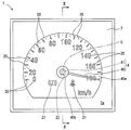
As shown in FIGS. 1 and 2, a
表示部材2は、ポリカーボネート樹脂等の透光性基材に遮光性印刷層を積層してなり、全体として平板状を呈している。表示部材2の一面である表示面2aは、視認側に向けて配置されている。図1に示すように、表示部材2において遮光性印刷層の開口した部分は、「車両状態値」を表示するために回転指針4の回転方向に並ぶ数字及び目盛を、指標20として形成している。ここで、本実施形態の「車両状態値」は図1の如き車速値であるが、車両に関連する例えばエンジン回転数等の物理量であってもよい。さらに、表示部材2において遮光性印刷層の開口した部分は、警告を発するための警告ランプ21を、回転指針4の回転軸41まわりに形成している。
The
「回転体」としての回転指針4は、アクリル樹脂等の透光性樹脂材料により形成され、指針本体40及び回転軸41を有している。指針本体40は、全体として細長針状を呈し、表示部材2の表示面2aよりも視認側に配置されている。指針本体40は、指標20の表す「車両状態値」を、先端40aにより回転位置に応じて指示する。図1,2に示すように回転軸41は、指針本体40の基端40bから反視認側へ延出する円柱状を、全体として呈している。回転軸41は、表示部材2において両面2a,2b間を貫通する指針孔22に、挿入されている。回転軸41は、表示部材2の背面2bよりも反視認側にてステップモータ6と連結されている。これによりステップモータ6は、回転軸41の軸線である回転中心線Cまわりに回転指針4を回転駆動することで、指針本体40による上記の指示を実現する。
The rotation pointer 4 as a “rotating body” is formed of a translucent resin material such as an acrylic resin, and has a pointer
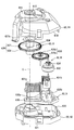
図2に示すようにステップモータ6は、表示部材2の背面2bよりも反視認側に配置されている。ステップモータ6は、モータケーシング60、モータ本体63、モータ基板64及び光源65,66を備えている。
As shown in FIG. 2, the stepping
図2,3に示すようにモータケーシング60は、一対のケース部材61,62を組み合わせてなり、全体として中空状を呈している。各ケース部材61,62は、変性ポリフェニレンエーテル樹脂(m-PPE)等の遮光性樹脂材料により形成され、それぞれカップ状に形成されている。各ケース部材61,62は、それぞれの開口縁部610,620同士を重ね合わせた状態で、スナップフィット嵌合により互いに結合されている。各ケース部材61,62は、指針本体40の回転中心線C上にて底部611,621を貫通する貫通孔612,622を、有している。第一ケース部材61は、表示部材2の反視認側にて背面2bと向き合って配置されている。第二ケース部材62は、第一ケース部材61よりも反視認側に配置されている。
As shown in FIGS. 2 and 3, the
図2に示すようにモータ基板64は、ガラスエポキシ基板等のプリント基板に金属配線層を積層してなり、全体として平板状を呈している。モータ基板64は、モータケーシング60よりも反視認側に配置されている。モータ基板64の一面である実装面640は、平面状を呈している。実装面640には、モータケーシング60及び光源65,66が保持されている。
As shown in FIG. 2, the
図2〜5に示すようにモータ本体63は、モータケーシング60内に収容されている。これにより、モータ基板64の実装面640には、モータ本体63がモータケーシング60を介して実装されている。モータ本体63は、駆動源D、減速機構R及び回転出力機構Oを備えている。
As shown in FIGS. 2 to 5, the motor
駆動源Dは、ヨーク630と二相コイル631a,631bとマグネットロータ632とを組み合わせてなり、指針本体40の回転中心線Cから径方向に外れて配置されている。ヨーク630は、鉄等の磁性金属材料により枠状に形成され、モータケーシング60に固定されている。ヨーク630は、内周側へ突出する一対の磁極630a,630bを有している。一方の磁極630aには、A相のコイル631aが巻装され、また他方の磁極630bには、B相のコイル631bが巻装されている。A,B各相のコイル631a,631bは、モータケーシング60のうち第二ケース部材62を貫通する通孔を通して、モータ基板64の金属配線層に電気接続されている。
The drive source D is composed of a combination of the
マグネットロータ632は、フェライト等の磁性金属材料により円盤状に形成され、各磁極630a,630bとの間に隙間をあけてヨーク630の内周側に配置されている。マグネットロータ632は、指針本体40の回転中心線Cと実質平行な軸線まわりに回転可能となるように、モータケーシング60によってラジアル支持且つスラスト支持されている。マグネットロータ632の外周部には、磁極としてのN,S極が回転方向に交互に着磁されている。
The
このような構成の駆動源DにおいてA,B各相のコイル631a,631bには、モータ基板64の金属配線層を介して外部の制御回路から、互いに位相の90度ずれた交流信号が印加される。これにより、それぞれのコイル631a,631bに発生する交流磁束は、ヨーク630からマグネットロータ632の間を通過することで、当該ロータ632を所定の回転位置まで駆動することになる。
In the driving source D having such a configuration, an AC signal whose phase is shifted by 90 degrees from an external control circuit is applied to the
減速機構Rは、マグネットギア634と中間ギア635とを組み合わせてなり、指針本体40の回転中心線Cから径方向に外れて配置されている。「第二減速ギア」としてのマグネットギア634は、ポリアセタール樹脂(POM)等の硬質樹脂材料により形成され、平歯車状を呈している。マグネットギア634は、マグネットロータ632と共に一体回転可能となるように、モータケーシング60によってラジアル支持且つスラスト支持されている。
The reduction mechanism R is a combination of a
「第一減速ギア」としての中間ギア635は、ポリブチレンテレフタレート樹脂(PBT)等の硬質樹脂材料により形成され、軸方向に並ぶ一対のギア部635a,635bを一体に有している。各ギア部635a,635bは、平歯車状を呈している。各ギア部635a,635bは、指針本体40の回転中心線Cと実質平行な軸線まわりに回転可能となるように、モータケーシング60によってラジアル支持且つスラスト支持されている。アイドルギア部635aは、後述の如く互いに噛合するピニオンギア部635b及び最終段ギア部638よりも、「軸方向一方側」となる反視認側にてマグネットギア634に噛合することで、当該ギア634の回転を減速する。
The
回転出力機構Oは、出力ギア636と回転ストッパ639とを組み合わせてなり、指針本体40の回転中心線C上に配置されている。出力ギア636と回転ストッパ639とは、ポリアセタール樹脂(POM)等の硬質樹脂材料により一体に形成されている。出力ギア636と回転ストッパ639とは、指針本体40の回転中心線Cまわりに一体回転可能となるように、モータケーシング60によってラジアル支持且つスラスト支持されている。
The rotation output mechanism O is a combination of an
出力ギア636は、出力軸部637及び最終段ギア部638を有している。出力軸部637は、全体として円筒状を呈している。出力軸部637の中心孔637aには、回転指針4のうち回転軸41が同軸上に圧入されている。これにより出力軸部637は、回転指針4と共に回転中心線Cまわりに回転することで、当該指針4に回転駆動力を出力する。最終段ギア部638は、出力軸部637から外周側へ広がる平歯車状を呈している。最終段ギア部638は、減速機構Rのうち中間ギア635のピニオンギア部635bに噛合することで、当該ギア635の回転を減速する。以上の構成からモータ本体63では、駆動源Dから減速機構Rの減速作用を経ることで増大された回転駆動力が、回転出力機構Oから回転指針4へと与えられる。
The
回転ストッパ639は、「軸方向他方側」となる視認側に最終段ギア部638から突出する突片状を、呈している。回転ストッパ639は、回転指針4の回転範囲を決める両側の限界位置にて、モータケーシング60の固定ストッパにより係止可能に設けられている。これにより、回転出力機構Oから回転指針4へ回転駆動力が与えられても、当該指針4が回転範囲外への回転を制限されるようになっている。
The
図2に示すように回転体照明光源65は、第二ケース部材62の貫通孔622内にて指針本体40の回転中心線C上に配置され、モータ基板64の実装面640に実装されている。回転体照明光源65は、LED(Light Emitting Diode)を主体としてなり、モータ基板64の金属配線層に電気接続されている。回転体照明光源65は、金属配線層を介して外部の制御回路から通電されることで、発光する。回転体照明光源65の発した光は、第二ケース部材62の貫通孔622及び出力軸部637の中心孔637aを通過して回転指針4の回転軸41に入射されることで、同指針4の指針本体40へと導かれる。これにより、回転指針4がモータ本体63を通して照明されることで、指針本体40が発光した状態にて視認される。
As shown in FIG. 2, the rotating body
表示照明光源66は、第二ケース部材62の周囲に複数配置され、モータ基板64の実装面640に実装されている。各表示照明光源66は、LEDを主体としてなり、モータ基板64の金属配線層に電気接続されている。各表示照明光源66は、金属配線層を介して外部の制御回路からそれぞれ必要警告時に通電されることで、発光する。表示照明光源66の発した光は、モータケーシング60の周囲を通過して表示部材2に入射される。これにより、表示部材2が直接的に照明されることで、必要警告時には警告ランプ21が発光した状態にて視認される。
A plurality of display
(倒れ抑制構造)
次に、図6〜9に示す第一実施形態の倒れ抑制構造8及びその関連構造について、詳細に説明する。尚、以下の説明では、図6〜9に示す回転中心線Cに沿う軸方向と、同線Cに実質垂直な径方向を、それぞれ単に軸方向と径方向という。
(Fall control structure)
Next, the
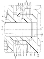
図6〜8に示すように出力ギア636の出力軸部637は、軸方向に最終段ギア部638を挟んで視認側と反視認側とにそれぞれ、第一外周ストレート部81と第二外周ストレート部82とを有している。換言すれば出力軸部637は、最終段ギア部638よりも「軸方向一方側」と「軸方向他方側」とにそれぞれ、第二外周ストレート部82と第一外周ストレート部81とを有している。
As shown in FIGS. 6 to 8, the
図6に示すように第一外周ストレート部81は、出力軸部637において視認側の先端637bから反視認側の最終段ギア部638までとなる所定の軸方向範囲に、設けられている。第一外周ストレート部81は、軸方向に沿ってストレートに延伸する円筒面状を、外周面にて呈している。図7,8に示すように第二外周ストレート部82は、出力軸部637において反視認側の基端637cから視認側の最終段ギア部638までとなる所定の軸方向範囲に、設けられている。第二外周ストレート部82は、軸方向に沿ってストレートに延伸する円筒面状を、外周面にて呈している。
As shown in FIG. 6, the first outer peripheral
図6に示すようにモータケーシング60の第一ケース部材61は、出力軸部637のまわりを同軸上に囲む貫通孔612のうち軸方向の一部によって形成された第一ラジアル軸受85を、有している。第一ラジアル軸受85は、第一ケース部材61において底部611の外面611aから反視認側へ離間した所定の軸方向範囲に、設けられている。第一ラジアル軸受85は、軸方向に沿ってストレートに延伸する円筒孔状を、内周面にて呈している。第一ラジアル軸受85の内径は、貫通孔612において同軸受85の軸方向両側に位置する部分の内径よりも、小径に設定されている。
As shown in FIG. 6, the first case member 61 of the
第一ラジアル軸受85の軸方向全域には、第一外周ストレート部81のうち軸方向の一部が同軸上に挿入されている。本実施形態において第一ラジアル軸受85の内周側には、挿入前にて同軸受85よりも僅かに小径に形成された第一外周ストレート部81が、相対摺動可能に嵌合している。これにより第一ラジアル軸受85は、最終段ギア部638よりも「軸方向一方側」の反視認側にて内周側に挿入された出力軸部637を、外周側からラジアル支持している。
In the entire area of the first
図7〜9に示すようにモータケーシング60の第二ケース部材62は、底部621から「軸方向他方側」の視認側へ突出する筒部624のうち軸方向一部によって形成された第二ラジアル軸受87を、有している。第二ラジアル軸受87は、第二ケース部材62において底部621から所定の軸方向範囲に、設けられている。第二ラジアル軸受87は、摺動支持部870及び遊挿部871を形成している。
As shown in FIGS. 7 to 9, a second radial member formed by a part of the
摺動支持部870は、第二ケース部材62の貫通孔622と同軸上に連なり且つ軸方向に沿ってストレートに延伸する有底円筒面状を、内周面にて呈している。摺動支持部870の内径は、貫通孔622の内径よりも大径に設定されている。これにより摺動支持部870の底面872は、円環平面状を呈している。遊挿部871は、第二ラジアル軸受87の視認側開口端を形成している。遊挿部871は、摺動支持部870と同軸上に連なり且つ軸方向に沿ってストレートに延伸する円筒面状を、内周面にて呈している。遊挿部871は、摺動支持部870の内径よりも大径に設定されている。
The inner peripheral surface of the sliding
図7,8に示すように、第二ラジアル軸受87では各部870,871の軸方向全域に、第二外周ストレート部82の軸方向一部ずつが同軸上に挿入されている。本実施形態において摺動支持部870の内周側には、同部870よりも僅かに小径に形成された第二外周ストレート部82が、相対摺動可能に嵌合している。また、本実施形態において摺動支持部870の底面872には、出力軸部637の基端637cにて円環平面状を呈する端面88が、相対摺動可能な面接触状態にて当接している。さらに、本実施形態において第二ラジアル軸受87の挿入入口部(即ち、視認側開口端)をなす遊挿部871の内周側には、第二外周ストレート部82が径方向隙間83をあけて遊挿されている。以上により第二ラジアル軸受87は、最終段ギア部638よりも反視認側にて内周側に挿入された出力軸部637をスラスト支持しつつ、同軸部637を外周側からラジアル支持している。
As shown in FIGS. 7 and 8, in the second
図7〜9に示すように第二ケース部材62は、筒部624の形成する第二ラジアル軸受87からさらに視認側へと突出する突起体89を、有している。
As shown in FIGS. 7 to 9, the
突起体89は、第二ケース部材62において第二ラジアル軸受87から所定の軸方向範囲に、設けられている。突起体89は、第二ラジアル軸受87のうち遊挿部871と同軸上に連なり且つ軸方向に沿ってストレート延伸する円弧面状を、内周面にて呈している。突起体89の内径は、第二ラジアル軸受87のうち摺動支持部870の内径よりも大径且つ同軸受87のうち遊挿部871と実質同一径に、設定されている。これにより、図7,8に示すように突起体89は、出力軸部637のうち第二ラジアル軸受87に挿入された第二外周ストレート部82との間に、径方向隙間84をあけている。この突起体89と第二外周ストレート部82との間の径方向隙間84は、第二ラジアル軸受87のうち遊挿部871と同ストレート部82との間の径方向隙間83に対し、径方向には実質同一幅をもって軸方向に連通している。尚、図7では、突起体89と第二ラジアル軸受87との境界線を、二点鎖線で模式的に示している。
The
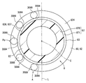
図7〜9に示すように本実施形態の突起体89は、出力ギア636において回転中心線Cを含む縦断面Lから、中間ギア635とは反対側に広がる空間としての特定領域Aにて、第二ラジアル軸受87から突出している。これにより、縦断面Lから中間ギア635とは反対側の特定領域Aでは、縦断面Lよりも中間ギア635側の領域に比べて、第二ラジアル軸受87を形成する筒部624の高さが突起体89の突出分だけ高くなっている。また本実施形態の突起体89は、特定領域Aにて回転中心線Cまわりとなる180°範囲の全域に連続して、広がっている。これより突起体89は、特定領域Aのうち回転中心線Cを径方向に挟んで中間ギア635の軸線とは反対側箇所Poにて、少なくとも設けられた構造となっている。
As shown in FIGS. 7 to 9, the
こうした構成の倒れ抑制構造8を備えたステップモータ6の製造は、図10に示すフローで実施される。まず、ステップS10の減速機構組み付け工程では、上向きに開口する第二ケース部材62内に駆動源D及びマグネットギア634を収容させた後、マグネットギア634に中間ギア635を噛合組み付けて、減速機構Rを完成させる。
The manufacture of the
続くステップS20の出力ギア組み付け工程では、上向きに開口する第二ケース部材62内にて、出力ギア636のうち出力軸部637の第二外周ストレート部82を第二ラジアル軸受87に挿入する。このとき出力ギア636のうち最終段ギア部638は、中間ギア635と適正に噛合する場合(図7の状態を参照)と、中間ギア635とは噛合しないで乗り上げる場合(図11の状態を参照)とが、発生すると想定される。
In the output gear assembling step of the subsequent step S20, the second outer
さらに続くステップS30の組み付け完了工程では、上向きに開口する第二ケース部材62内にて、出力ギア636を振動させながら第二ラジアル軸受87側へと押圧する。これにより、最終段ギア部638と中間ギア635との噛合完了を確認して回転出力機構Oを完成させた後には、第一ケース部材61を第二ケース部材62に組み付けしてから、それらケース部材61,62をモータ基板64に保持させる。尚、こうして製造の完了するステップモータ6は、当該製造完了後にて車両用指針計器1に組み込まれてから、車両に搭載されることとなる。
In the assembling completion process of the following step S30, the
(作用効果)
以上説明した第一実施形態の作用効果を、以下に説明する。
(Effects)
The operation and effect of the first embodiment described above will be described below.
第一実施形態によると、出力ギア636の最終段ギア部638よりも「軸方向一方側」である第二ラジアル軸受87側にて、当該ギア部638の噛合する中間ギア635がマグネットギア634と噛合する。この第一実施形態による噛合構成は、第二ラジアル軸受87とは反対側の「軸方向他方側」へ最終段ギア部638から回転ストッパ639の突出する出力ギア636を、小型に配置するのに適している。そこで、こうした噛合構成により製造時には、出力ギア636の出力軸部637を第二ラジアル軸受87に挿入しながら、事前に噛合されたギア635,634のうち中間ギア635に、出力ギア636の最終段ギア部638を噛合させることとなる。このとき第一実施形態では、図11に示すように最終段ギア部638が中間ギア635に噛合し難いために乗り上げたとしても、出力ギア636の倒れは抑制され得る。
According to the first embodiment, on the side of the second
これは図11に示すように、中間ギア635による最終段ギア部638の支持箇所P1と、第二ラジアル軸受87による出力軸部637の支持箇所P2とは、本来の回転中心線Cよりも中間ギア635側に偏るものの、当該回転中心線Cよりも中間ギア635とは反対側には、出力軸部637の支持箇所P3が追加されるからである。ここで追加される出力軸部637の支持箇所P3は、本来の回転中心線Cを含む縦断面Lから中間ギア635とは反対側に広がる特定領域Aにて、「軸方向他方側」である最終段ギア部638側へ第二ラジアル軸受87から突出した突起体89が出力軸部637を支持することで、現出する。
This is because, as shown in FIG. 11, the supporting point P1 of the
以上によれば、出力ギア636が安定した支持状態となるので、最終段ギア部638が中間ギア635に乗り上げて傾いたとしても、出力ギア636の倒れまでは抑制することができる。特に第一実施形態では、第二ラジアル軸受87の挿入入口部と出力軸部637の第二外周ストレート部82との間に径方向隙間83が存在しているものの、出力ギア636が安定した支持状態となるので、出力ギア636の倒れ抑制効果は顕著に発揮され得る。また、こうした出力ギア636の倒れ抑制効果は、例えば図10の製造フローにおけるステップS20,S30間にて第二ケース部材62を移動搬送させるような場合に、特に有効である。したがって、このようなことから製造時には生産性を確保することが可能となる。
According to the above, since the
ここで第一実施形態によると、中間ギア635に乗り上げた出力ギア636は、特定領域Aのうち回転中心線Cを径方向に挟んで中間ギア635と反対側へは、特に傾き易い。そこで、特定領域Aのうち回転中心線Cを径方向に挟んで中間ギア635と反対側箇所Poには、少なくとも突起体89が設けられるので、当該箇所Poが突起体89による出力軸部637の支持箇所P3となり易い。故に、製造時にて出力ギア636が中間ギア635に乗り上げて傾いたとしても、出力ギア636の倒れを抑制する効果の確実性を高めて、生産性を確保することが可能となる。
Here, according to the first embodiment, the
さらに第一実施形態によると、特定領域Aにて回転中心線Cまわりの全域は、中間ギア635に乗り上げた出力ギア636の傾く側を全面的にカバーし得る。そこで、特定領域Aにて回転中心線Cまわりの全域に広がる突起体89によれば、出力軸部637の支持箇所P3を確実に現出させることができる。故に、製造時にて出力ギア636が中間ギア635に乗り上げて傾いたとしても、出力ギア636の倒れ抑制する効果を保証して、生産性を確保することが可能となる。
Further, according to the first embodiment, the entire area around the rotation center line C in the specific area A can entirely cover the inclined side of the
またさらに第一実施形態によると、第二ラジアル軸受87に挿入された出力軸部637との間に径方向隙間84をあける突起体89は、製造時には第二ラジアル軸受87へ挿入される出力軸部637には干渉し難くなる。故に、こうした突起体89によれば、出力ギア636の倒れだけでなく、出力軸部637の挿入干渉をも抑制して、生産性を向上させることが可能となる。
Still further, according to the first embodiment, the
(第二実施形態)
図12,13に示すように本発明の第二実施形態は、第一実施形態の変形例である。
(Second embodiment)
As shown in FIGS. 12 and 13, the second embodiment of the present invention is a modification of the first embodiment.
第二実施形態による突起体2089の内径は、遊挿部871のない第二ラジアル軸受2087における摺動支持部870の内径と実質同一径に、設定されている。これにより突起体2089は、出力軸部637のうち第二ラジアル軸受87に挿入された第二外周ストレート部82を、外周側からラジアル支持している。尚、突起体2089及び第二ラジアル軸受2087について、以上説明した以外の構成は、第一実施形態による突起体89及び第二ラジアル軸受2087の構成に準じたものとなっている。
The inner diameter of the
このような第二実施形態によると、第二ラジアル軸受2087に挿入された出力軸部637を突起体2089が外周側からラジアル支持することで、中間ギア635から最終段ギア部638の受ける反力により出力ギア636が傾くのを規制することができる。これによれば、製造時における生産性だけでなく、製造後における作動安定性も確保することが可能となる。
According to such a second embodiment, the
(第三実施形態)
図14,15に示すように本発明の第三実施形態は、第一実施形態の変形例である。第三実施形態による突起体3089は、特定領域Aにて回転中心線Cまわりに実質等間隔に分散して、複数配置されている。各突起体3089は、第二ラジアル軸受87のうち遊挿部871の内径と実質同一径の仮想円に内周部が沿う円弧柱状を、呈している。これにより各突起体3089は、出力軸部637のうち第二ラジアル軸受87に挿入された第二外周ストレート部82との間にて、径方向隙間83と軸方向連通する径方向隙間3084をそれぞれあけている。また、特定領域Aのうち回転中心線Cを径方向に挟んで中間ギア635とは反対側箇所Poには、複数のうち特定の一突起体3089aが少なくとも設けられている。尚、各突起体3089について、以上説明した以外の構成は、第一実施形態による突起体89の構成に準じたものとなっている。
(Third embodiment)
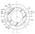
As shown in FIGS. 14 and 15, the third embodiment of the present invention is a modification of the first embodiment. A plurality of
このような第三実施形態によると、特定領域Aにて回転中心線Cまわりに分散された複数の突起体3089は、中間ギア635に乗り上げた出力ギア636の傾く側をカバーして、出力軸部637の支持箇所P3を現出させ易い。故に、製造時にて出力ギア636が中間ギア635に乗り上げて傾いたとしても、出力ギア636の倒れを抑制する効果の確実性を高めて、生産性を確保することが可能となる。
According to such a third embodiment, the plurality of
(他の実施形態)
以上、本発明の複数の実施形態について説明したが、本発明は、それらの実施形態に限定して解釈されるものではなく、本発明の要旨を逸脱しない範囲内において種々の実施形態及び組み合わせに適用することができる。尚、以下において、図16〜18は第一実施形態に関する変形例を代表的に示し、図19は第二実施形態に関する変形例を代表的に示し、図20〜23は第三実施形態に関する変形例を代表的に示している。
(Other embodiments)
As described above, a plurality of embodiments of the present invention have been described. However, the present invention is not construed as being limited to those embodiments, and may be applied to various embodiments and combinations without departing from the gist of the present invention. Can be applied. In the following, FIGS. 16 to 18 exemplarily show modifications of the first embodiment, FIG. 19 exemplarily shows modifications of the second embodiment, and FIGS. 20 to 23 show modifications of the third embodiment. An example is shown representatively.
具体的に第一実施形態に関する変形例1では、図16に示すように、突起体89の内周面と第二ラジアル軸受87のうち遊挿部871の内周面とを、同軸受87のうち摺動支持部870へと向かって漸次縮径するテーパ面状に形成してもよい。
Specifically, in the first modification of the first embodiment, as shown in FIG. 16, the inner peripheral surface of the
第一及び第二実施形態に関する変形例2では、図17〜19に示すように、特定領域Aにて回転中心線Cまわりとなる180°未満の範囲に、突起体89,2089を設けてもよい。ここで特に、第一実施形態に関する変形例2では、図18に示すように突起体89を、遊挿部871の内径と実質同一径の仮想円に接する円柱状等のピン形状に形成して、第二外周ストレート部82との間に径方向隙間84をあけさせてもよい。また同様に、第二実施形態に関する変形例2では、図19に示すように突起体2089を、摺動支持部870の内径と実質同一径の仮想円に接する円柱状等のピン形状に形成して、第二外周ストレート部82を外周側から支持させてもよい。
In the second modification of the first and second embodiments, as shown in FIGS. 17 to 19, the
第三実施形態に関する変形例3では、図20に示すように、特定領域Aのうち回転中心線Cを径方向に挟んで中間ギア635とは反対側箇所Poを避けて、各突起体3089を設けてもよい。第三実施形態に関する変形例4では、図21に示すように第二実施形態に準じた第二ラジアル軸受2087の採用下にて各突起体3089を、摺動支持部870の内径と実質同一径の仮想円に内周部が沿う円弧柱状に形成して、第二外周ストレート部82を外周側からラジアル支持させてもよい。
In the third modification of the third embodiment, as shown in FIG. 20, each of the
第三実施形態に関する変形例5では、図22に示すように各突起体3089を、遊挿部871の内径と実質同一径の仮想円に接する円柱状等のピン形状に形成して、第二外周ストレート部82との間に径方向隙間3084をあけさせてもよい。第三実施形態に関する変形例6では、図23に示すように第二実施形態に準じた第二ラジアル軸受2087の採用下にて各突起体3089を、摺動支持部870の内径と実質同一径の仮想円に接する円柱状等のピン形状に形成して、第二外周ストレート部82を外周側から支持させてもよい。
In Modification Example 5 relating to the third embodiment, as shown in FIG. 22, each
第一〜第三実施形態に関する変形例7では、ヘッドアップディスプレイ(HUD)等、車両用指針計器1以外の装置に本発明を適用して、当該装置の「回転体」をステップモータ6により回転駆動してもよい。
In a seventh modification of the first to third embodiments, the present invention is applied to a device other than the
1 車両用指針計器、4 回転指針、6 ステップモータ、8 倒れ抑制構造、41 回転軸、60 モータケーシング、61 第一ケース部材、62 第二ケース部材、63 モータ本体、82 第二外周ストレート部、83,84,3084 径方向隙間、87,2087 第二ラジアル軸受、89,2089,3089,3089a 突起体、634 マグネットギア、635 中間ギア、635a アイドルギア部、635b ピニオンギア部、636 出力ギア、637 出力軸部、638 最終段ギア部、870 摺動支持部、871 遊挿部、A 特定領域、C 回転中心線、L 縦断面、O 回転出力機構、P1,P2,P3 支持箇所、Po 反対側箇所、R 減速機構
DESCRIPTION OF
Claims (7)
前記回転軸の外周を囲む円筒状に形成されて前記回転体と共に回転中心線(C)まわりに回転する出力軸部(637)、及び前記出力軸部から外周側へ広がっている最終段ギア部(638)を、有する出力ギア(636)と、
前記最終段ギア部よりも軸方向一方側にて内周側に挿入された前記出力軸部を、ラジアル支持しているラジアル軸受(87,2087)と、
前記最終段ギア部が噛合している第一減速ギア(635)、及び前記最終段ギア部よりも前記軸方向一方側にて前記第一減速ギアが噛合している第二減速ギア(634)を、有する減速機構(R)と、
前記出力ギアにおいて前記回転中心線を含む縦断面(L)から前記第一減速ギアとは反対側に広がる特定領域(A)にて、前記ラジアル軸受から軸方向他方側へ突出している突起体(89,2089,3089)とを、備え、
前記突起体は、前記特定領域のうち、前記回転中心線まわりの180°以下の範囲に設けられているステップモータ。 A step motor (6) for rotatingly driving a rotating body (4) having a rotating shaft (41),
An output shaft portion (637) formed in a cylindrical shape surrounding the outer periphery of the rotation shaft and rotating around a rotation center line (C) together with the rotating body, and a final stage gear portion extending from the output shaft portion to the outer periphery side An output gear (636) having (638);
Radial bearings (87, 2087) for radially supporting the output shaft portion inserted on the inner peripheral side at one axial side of the final gear portion;
A first reduction gear (635) meshed with the final gear portion, and a second reduction gear (634) meshed with the first reduction gear on one axial side of the final gear portion. A reduction mechanism (R) having
In the specific area (A) of the output gear, which extends from the longitudinal section (L) including the rotation center line to the opposite side to the first reduction gear, a projection ( 89, 2089, 3089) .
The step motor wherein the protrusion is provided in a range of 180 ° or less around the rotation center line in the specific area .
前記回転体として車両状態値を指示する回転指針(4)とを、含んで構成されている車両用指針計器。 A step motor (6) according to any one of claims 1 to 6,
A pointer indicator for a vehicle, comprising: a rotation indicator (4) for indicating a vehicle state value as the rotating body.
Priority Applications (6)
| Application Number | Priority Date | Filing Date | Title |
|---|---|---|---|
| JP2017079881A JP6673282B2 (en) | 2017-04-13 | 2017-04-13 | Step motors and pointer instruments for vehicles |
| KR1020197026434A KR20190116406A (en) | 2017-04-13 | 2018-03-05 | Instruction Instruments for Step Motors and Vehicles |
| DE112018001994.2T DE112018001994T5 (en) | 2017-04-13 | 2018-03-05 | Stepper motor and indicator device for a vehicle |
| CN201880013376.2A CN110325827B (en) | 2017-04-13 | 2018-03-05 | Stepping motor and pointer instrument for vehicle |
| PCT/JP2018/008211 WO2018190029A1 (en) | 2017-04-13 | 2018-03-05 | Step motor and indicator instrument for vehicles |
| US16/566,125 US11274730B2 (en) | 2017-04-13 | 2019-09-10 | Step motor and indicator instrument for vehicle |
Applications Claiming Priority (1)
| Application Number | Priority Date | Filing Date | Title |
|---|---|---|---|
| JP2017079881A JP6673282B2 (en) | 2017-04-13 | 2017-04-13 | Step motors and pointer instruments for vehicles |
Publications (3)
| Publication Number | Publication Date |
|---|---|
| JP2018179767A JP2018179767A (en) | 2018-11-15 |
| JP2018179767A5 JP2018179767A5 (en) | 2019-04-11 |
| JP6673282B2 true JP6673282B2 (en) | 2020-03-25 |
Family
ID=63793161
Family Applications (1)
| Application Number | Title | Priority Date | Filing Date |
|---|---|---|---|
| JP2017079881A Active JP6673282B2 (en) | 2017-04-13 | 2017-04-13 | Step motors and pointer instruments for vehicles |
Country Status (6)
| Country | Link |
|---|---|
| US (1) | US11274730B2 (en) |
| JP (1) | JP6673282B2 (en) |
| KR (1) | KR20190116406A (en) |
| CN (1) | CN110325827B (en) |
| DE (1) | DE112018001994T5 (en) |
| WO (1) | WO2018190029A1 (en) |
Families Citing this family (1)
| Publication number | Priority date | Publication date | Assignee | Title |
|---|---|---|---|---|
| JP6733593B2 (en) * | 2017-04-13 | 2020-08-05 | 株式会社デンソー | Step motor and vehicle pointer instrument |
Family Cites Families (8)
| Publication number | Priority date | Publication date | Assignee | Title |
|---|---|---|---|---|
| JP2001281361A (en) * | 2000-04-03 | 2001-10-10 | Rhythm Watch Co Ltd | Movement for timepiece |
| JP2003254797A (en) * | 2002-03-01 | 2003-09-10 | Denso Corp | Internal rotary device for pointer instrument |
| JP5255480B2 (en) | 2009-02-18 | 2013-08-07 | 矢崎総業株式会社 | Driving device for indicating instrument |
| JP5545946B2 (en) | 2009-11-09 | 2014-07-09 | 矢崎総業株式会社 | Illumination structure of meter device |
| JP5735851B2 (en) * | 2011-04-28 | 2015-06-17 | 矢崎総業株式会社 | Pointer device and meter device with the same |
| JP2015152157A (en) | 2014-02-19 | 2015-08-24 | 矢崎総業株式会社 | power transmission gear unit and instrument for vehicle |
| JP6460749B2 (en) | 2014-11-21 | 2019-01-30 | 日本電産サンキョー株式会社 | Geared motor and pointer type display device |
| JP2017079881A (en) | 2015-10-23 | 2017-05-18 | 株式会社プレックス | Fabric type identification device and identification method |
-
2017
- 2017-04-13 JP JP2017079881A patent/JP6673282B2/en active Active
-
2018
- 2018-03-05 DE DE112018001994.2T patent/DE112018001994T5/en active Pending
- 2018-03-05 WO PCT/JP2018/008211 patent/WO2018190029A1/en active Application Filing
- 2018-03-05 CN CN201880013376.2A patent/CN110325827B/en active Active
- 2018-03-05 KR KR1020197026434A patent/KR20190116406A/en not_active Application Discontinuation
-
2019
- 2019-09-10 US US16/566,125 patent/US11274730B2/en active Active
Also Published As
| Publication number | Publication date |
|---|---|
| WO2018190029A1 (en) | 2018-10-18 |
| DE112018001994T5 (en) | 2019-12-19 |
| US11274730B2 (en) | 2022-03-15 |
| CN110325827B (en) | 2021-07-09 |
| US20200003278A1 (en) | 2020-01-02 |
| CN110325827A (en) | 2019-10-11 |
| JP2018179767A (en) | 2018-11-15 |
| KR20190116406A (en) | 2019-10-14 |
Similar Documents
| Publication | Publication Date | Title |
|---|---|---|
| JP6733593B2 (en) | Step motor and vehicle pointer instrument | |
| JP6044838B2 (en) | Head-up display device | |
| JP5099421B2 (en) | Indicator device | |
| JP6016273B2 (en) | Rotary actuator and operation feeling imparting type input device using the same | |
| JP6652102B2 (en) | Step motors and pointer instruments for vehicles | |
| JP6673282B2 (en) | Step motors and pointer instruments for vehicles | |
| JP2013013222A (en) | Stepping motor | |
| JP2010190748A (en) | Driving device for indicating instrument | |
| US11639104B2 (en) | Indicator instrument for vehicle | |
| JP2011223776A (en) | Instrument unit | |
| JP5007936B2 (en) | Indicator device | |
| JP2016114508A (en) | Ring row mechanism, movement and clock | |
| JP6485344B2 (en) | Display position adjustment unit and head-up display device | |
| JP5594823B2 (en) | Pointer unit | |
| JP4292515B2 (en) | Pointer-type instrument | |
| JP2022164412A (en) | power transmission device | |
| JP6156097B2 (en) | Instrument | |
| CN108983415B (en) | Rotary driving device | |
| JP2021067536A (en) | Rotation drive device and indicator instrument for vehicles | |
| JP2017207551A (en) | Display position adjustment unit and head-up display device | |
| JP2021078174A (en) | Rotary drive device and vehicular pointer instrument | |
| JP5524706B2 (en) | Instrument unit | |
| JP5437892B2 (en) | Instrument unit | |
| JP2008268138A (en) | Indicator instrument device | |
| JPH09222338A (en) | Stepping motor type measuring instrument |
Legal Events
| Date | Code | Title | Description |
|---|---|---|---|
| A521 | Request for written amendment filed |
Free format text: JAPANESE INTERMEDIATE CODE: A523 Effective date: 20190226 |
|
| A621 | Written request for application examination |
Free format text: JAPANESE INTERMEDIATE CODE: A621 Effective date: 20190226 |
|
| A131 | Notification of reasons for refusal |
Free format text: JAPANESE INTERMEDIATE CODE: A131 Effective date: 20191112 |
|
| A521 | Request for written amendment filed |
Free format text: JAPANESE INTERMEDIATE CODE: A523 Effective date: 20191226 |
|
| TRDD | Decision of grant or rejection written | ||
| A01 | Written decision to grant a patent or to grant a registration (utility model) |
Free format text: JAPANESE INTERMEDIATE CODE: A01 Effective date: 20200204 |
|
| A61 | First payment of annual fees (during grant procedure) |
Free format text: JAPANESE INTERMEDIATE CODE: A61 Effective date: 20200217 |
|
| R151 | Written notification of patent or utility model registration |
Ref document number: 6673282 Country of ref document: JP Free format text: JAPANESE INTERMEDIATE CODE: R151 |
|
| R250 | Receipt of annual fees |
Free format text: JAPANESE INTERMEDIATE CODE: R250 |
|
| R250 | Receipt of annual fees |
Free format text: JAPANESE INTERMEDIATE CODE: R250 |