JP6673178B2 - Vehicle control device and vehicle control method - Google Patents
Vehicle control device and vehicle control method Download PDFInfo
- Publication number
- JP6673178B2 JP6673178B2 JP2016242667A JP2016242667A JP6673178B2 JP 6673178 B2 JP6673178 B2 JP 6673178B2 JP 2016242667 A JP2016242667 A JP 2016242667A JP 2016242667 A JP2016242667 A JP 2016242667A JP 6673178 B2 JP6673178 B2 JP 6673178B2
- Authority
- JP
- Japan
- Prior art keywords
- vehicle
- width
- ratio
- collision
- overlap
- Prior art date
- Legal status (The legal status is an assumption and is not a legal conclusion. Google has not performed a legal analysis and makes no representation as to the accuracy of the status listed.)
- Active
Links
- 238000000034 method Methods 0.000 title claims description 19
- 230000009467 reduction Effects 0.000 claims description 21
- 230000008859 change Effects 0.000 claims description 9
- 230000008569 process Effects 0.000 description 9
- 230000006870 function Effects 0.000 description 8
- 230000007423 decrease Effects 0.000 description 7
- 238000001514 detection method Methods 0.000 description 5
- 238000010586 diagram Methods 0.000 description 4
- 230000000694 effects Effects 0.000 description 4
- 230000004927 fusion Effects 0.000 description 4
- 230000003287 optical effect Effects 0.000 description 3
- 230000005540 biological transmission Effects 0.000 description 2
- 230000003111 delayed effect Effects 0.000 description 2
- 238000003384 imaging method Methods 0.000 description 2
- 230000004913 activation Effects 0.000 description 1
- 238000011156 evaluation Methods 0.000 description 1
- 239000000284 extract Substances 0.000 description 1
- 230000000116 mitigating effect Effects 0.000 description 1
Images


Classifications
-
- B—PERFORMING OPERATIONS; TRANSPORTING
- B60—VEHICLES IN GENERAL
- B60W—CONJOINT CONTROL OF VEHICLE SUB-UNITS OF DIFFERENT TYPE OR DIFFERENT FUNCTION; CONTROL SYSTEMS SPECIALLY ADAPTED FOR HYBRID VEHICLES; ROAD VEHICLE DRIVE CONTROL SYSTEMS FOR PURPOSES NOT RELATED TO THE CONTROL OF A PARTICULAR SUB-UNIT
- B60W30/00—Purposes of road vehicle drive control systems not related to the control of a particular sub-unit, e.g. of systems using conjoint control of vehicle sub-units, or advanced driver assistance systems for ensuring comfort, stability and safety or drive control systems for propelling or retarding the vehicle
- B60W30/08—Active safety systems predicting or avoiding probable or impending collision or attempting to minimise its consequences
- B60W30/09—Taking automatic action to avoid collision, e.g. braking and steering
-
- B—PERFORMING OPERATIONS; TRANSPORTING
- B60—VEHICLES IN GENERAL
- B60W—CONJOINT CONTROL OF VEHICLE SUB-UNITS OF DIFFERENT TYPE OR DIFFERENT FUNCTION; CONTROL SYSTEMS SPECIALLY ADAPTED FOR HYBRID VEHICLES; ROAD VEHICLE DRIVE CONTROL SYSTEMS FOR PURPOSES NOT RELATED TO THE CONTROL OF A PARTICULAR SUB-UNIT
- B60W10/00—Conjoint control of vehicle sub-units of different type or different function
- B60W10/18—Conjoint control of vehicle sub-units of different type or different function including control of braking systems
-
- B—PERFORMING OPERATIONS; TRANSPORTING
- B60—VEHICLES IN GENERAL
- B60W—CONJOINT CONTROL OF VEHICLE SUB-UNITS OF DIFFERENT TYPE OR DIFFERENT FUNCTION; CONTROL SYSTEMS SPECIALLY ADAPTED FOR HYBRID VEHICLES; ROAD VEHICLE DRIVE CONTROL SYSTEMS FOR PURPOSES NOT RELATED TO THE CONTROL OF A PARTICULAR SUB-UNIT
- B60W30/00—Purposes of road vehicle drive control systems not related to the control of a particular sub-unit, e.g. of systems using conjoint control of vehicle sub-units, or advanced driver assistance systems for ensuring comfort, stability and safety or drive control systems for propelling or retarding the vehicle
- B60W30/08—Active safety systems predicting or avoiding probable or impending collision or attempting to minimise its consequences
- B60W30/095—Predicting travel path or likelihood of collision
- B60W30/0956—Predicting travel path or likelihood of collision the prediction being responsive to traffic or environmental parameters
-
- B—PERFORMING OPERATIONS; TRANSPORTING
- B60—VEHICLES IN GENERAL
- B60W—CONJOINT CONTROL OF VEHICLE SUB-UNITS OF DIFFERENT TYPE OR DIFFERENT FUNCTION; CONTROL SYSTEMS SPECIALLY ADAPTED FOR HYBRID VEHICLES; ROAD VEHICLE DRIVE CONTROL SYSTEMS FOR PURPOSES NOT RELATED TO THE CONTROL OF A PARTICULAR SUB-UNIT
- B60W50/00—Details of control systems for road vehicle drive control not related to the control of a particular sub-unit, e.g. process diagnostic or vehicle driver interfaces
- B60W50/08—Interaction between the driver and the control system
- B60W50/14—Means for informing the driver, warning the driver or prompting a driver intervention
-
- G—PHYSICS
- G01—MEASURING; TESTING
- G01S—RADIO DIRECTION-FINDING; RADIO NAVIGATION; DETERMINING DISTANCE OR VELOCITY BY USE OF RADIO WAVES; LOCATING OR PRESENCE-DETECTING BY USE OF THE REFLECTION OR RERADIATION OF RADIO WAVES; ANALOGOUS ARRANGEMENTS USING OTHER WAVES
- G01S13/00—Systems using the reflection or reradiation of radio waves, e.g. radar systems; Analogous systems using reflection or reradiation of waves whose nature or wavelength is irrelevant or unspecified
- G01S13/86—Combinations of radar systems with non-radar systems, e.g. sonar, direction finder
- G01S13/867—Combination of radar systems with cameras
-
- G—PHYSICS
- G01—MEASURING; TESTING
- G01S—RADIO DIRECTION-FINDING; RADIO NAVIGATION; DETERMINING DISTANCE OR VELOCITY BY USE OF RADIO WAVES; LOCATING OR PRESENCE-DETECTING BY USE OF THE REFLECTION OR RERADIATION OF RADIO WAVES; ANALOGOUS ARRANGEMENTS USING OTHER WAVES
- G01S13/00—Systems using the reflection or reradiation of radio waves, e.g. radar systems; Analogous systems using reflection or reradiation of waves whose nature or wavelength is irrelevant or unspecified
- G01S13/88—Radar or analogous systems specially adapted for specific applications
- G01S13/93—Radar or analogous systems specially adapted for specific applications for anti-collision purposes
- G01S13/931—Radar or analogous systems specially adapted for specific applications for anti-collision purposes of land vehicles
-
- G—PHYSICS
- G06—COMPUTING; CALCULATING OR COUNTING
- G06V—IMAGE OR VIDEO RECOGNITION OR UNDERSTANDING
- G06V20/00—Scenes; Scene-specific elements
- G06V20/50—Context or environment of the image
- G06V20/56—Context or environment of the image exterior to a vehicle by using sensors mounted on the vehicle
- G06V20/58—Recognition of moving objects or obstacles, e.g. vehicles or pedestrians; Recognition of traffic objects, e.g. traffic signs, traffic lights or roads
-
- G—PHYSICS
- G08—SIGNALLING
- G08G—TRAFFIC CONTROL SYSTEMS
- G08G1/00—Traffic control systems for road vehicles
- G08G1/16—Anti-collision systems
- G08G1/166—Anti-collision systems for active traffic, e.g. moving vehicles, pedestrians, bikes
-
- B—PERFORMING OPERATIONS; TRANSPORTING
- B60—VEHICLES IN GENERAL
- B60W—CONJOINT CONTROL OF VEHICLE SUB-UNITS OF DIFFERENT TYPE OR DIFFERENT FUNCTION; CONTROL SYSTEMS SPECIALLY ADAPTED FOR HYBRID VEHICLES; ROAD VEHICLE DRIVE CONTROL SYSTEMS FOR PURPOSES NOT RELATED TO THE CONTROL OF A PARTICULAR SUB-UNIT
- B60W50/00—Details of control systems for road vehicle drive control not related to the control of a particular sub-unit, e.g. process diagnostic or vehicle driver interfaces
- B60W50/08—Interaction between the driver and the control system
- B60W50/14—Means for informing the driver, warning the driver or prompting a driver intervention
- B60W2050/143—Alarm means
-
- B—PERFORMING OPERATIONS; TRANSPORTING
- B60—VEHICLES IN GENERAL
- B60W—CONJOINT CONTROL OF VEHICLE SUB-UNITS OF DIFFERENT TYPE OR DIFFERENT FUNCTION; CONTROL SYSTEMS SPECIALLY ADAPTED FOR HYBRID VEHICLES; ROAD VEHICLE DRIVE CONTROL SYSTEMS FOR PURPOSES NOT RELATED TO THE CONTROL OF A PARTICULAR SUB-UNIT
- B60W2420/00—Indexing codes relating to the type of sensors based on the principle of their operation
- B60W2420/40—Photo or light sensitive means, e.g. infrared sensors
- B60W2420/403—Image sensing, e.g. optical camera
-
- B60W2420/408—
-
- B—PERFORMING OPERATIONS; TRANSPORTING
- B60—VEHICLES IN GENERAL
- B60W—CONJOINT CONTROL OF VEHICLE SUB-UNITS OF DIFFERENT TYPE OR DIFFERENT FUNCTION; CONTROL SYSTEMS SPECIALLY ADAPTED FOR HYBRID VEHICLES; ROAD VEHICLE DRIVE CONTROL SYSTEMS FOR PURPOSES NOT RELATED TO THE CONTROL OF A PARTICULAR SUB-UNIT
- B60W2420/00—Indexing codes relating to the type of sensors based on the principle of their operation
- B60W2420/50—Magnetic or electromagnetic sensors
-
- B—PERFORMING OPERATIONS; TRANSPORTING
- B60—VEHICLES IN GENERAL
- B60W—CONJOINT CONTROL OF VEHICLE SUB-UNITS OF DIFFERENT TYPE OR DIFFERENT FUNCTION; CONTROL SYSTEMS SPECIALLY ADAPTED FOR HYBRID VEHICLES; ROAD VEHICLE DRIVE CONTROL SYSTEMS FOR PURPOSES NOT RELATED TO THE CONTROL OF A PARTICULAR SUB-UNIT
- B60W2554/00—Input parameters relating to objects
-
- G—PHYSICS
- G01—MEASURING; TESTING
- G01S—RADIO DIRECTION-FINDING; RADIO NAVIGATION; DETERMINING DISTANCE OR VELOCITY BY USE OF RADIO WAVES; LOCATING OR PRESENCE-DETECTING BY USE OF THE REFLECTION OR RERADIATION OF RADIO WAVES; ANALOGOUS ARRANGEMENTS USING OTHER WAVES
- G01S13/00—Systems using the reflection or reradiation of radio waves, e.g. radar systems; Analogous systems using reflection or reradiation of waves whose nature or wavelength is irrelevant or unspecified
- G01S13/88—Radar or analogous systems specially adapted for specific applications
- G01S13/93—Radar or analogous systems specially adapted for specific applications for anti-collision purposes
- G01S13/931—Radar or analogous systems specially adapted for specific applications for anti-collision purposes of land vehicles
- G01S2013/93185—Controlling the brakes
-
- G—PHYSICS
- G01—MEASURING; TESTING
- G01S—RADIO DIRECTION-FINDING; RADIO NAVIGATION; DETERMINING DISTANCE OR VELOCITY BY USE OF RADIO WAVES; LOCATING OR PRESENCE-DETECTING BY USE OF THE REFLECTION OR RERADIATION OF RADIO WAVES; ANALOGOUS ARRANGEMENTS USING OTHER WAVES
- G01S7/00—Details of systems according to groups G01S13/00, G01S15/00, G01S17/00
- G01S7/02—Details of systems according to groups G01S13/00, G01S15/00, G01S17/00 of systems according to group G01S13/00
- G01S7/41—Details of systems according to groups G01S13/00, G01S15/00, G01S17/00 of systems according to group G01S13/00 using analysis of echo signal for target characterisation; Target signature; Target cross-section
Description
本発明は、車両制御装置及び車両制御方法に関する。 The present invention relates to a vehicle control device and a vehicle control method.
従来、自車前方の物体と自車両との横方向での重なり率を算出し、この重なり率に基づいて、物体と自車両との衝突回避制御の作動タイミングを設定する車両制御装置が知られている。重なり率は、自車前方に位置する物体と自車両との衝突の危険性を判定するための指標値である。例えば、車両制御装置は、自車前方を撮像した撮像画像に基づいて、物体の横方向の大きさを示す物体幅を算出する。そして、自車前方に仮想的に設定された判定幅に重なる物体幅の横方向の長さに基づいて、重なり率を算出する。 2. Description of the Related Art Conventionally, there has been known a vehicle control device that calculates a lateral overlap ratio between an object in front of a host vehicle and a host vehicle in a lateral direction, and sets an operation timing of collision avoidance control between the object and the host vehicle based on the overlap ratio. ing. The overlap ratio is an index value for determining the risk of collision between an object located in front of the host vehicle and the host vehicle. For example, the vehicle control device calculates an object width indicating the size of the object in the lateral direction based on a captured image of the front of the vehicle. Then, the overlap ratio is calculated based on the horizontal length of the object width overlapping the determination width virtually set in front of the own vehicle.
特許文献1には、自車両を所定駐車位置へ駐車する場合や、所定駐車位置から発進させる場合に、自車周囲の駐車車両と自車両との重なり率を変更する装置が開示されている。
ところで、物体幅を撮像画像から検出する場合、物体の形状を誤認識することで物体幅を大きめに算出してしまう場合があった。例えば、車両制御装置が物体幅を大きめに算出してしまうと重なり率が増加し、衝突回避制御の作動タイミングが変更される場合がある。衝突回避制御の作動タイミングが変更されることで、衝突回避制御の不要作動の要因となるおそれがある。 By the way, when the object width is detected from the captured image, there is a case where the object width is calculated to be relatively large by erroneously recognizing the shape of the object. For example, when the vehicle control device calculates the object width to be large, the overlap ratio increases, and the operation timing of the collision avoidance control may be changed. Changing the operation timing of the collision avoidance control may cause unnecessary operation of the collision avoidance control.
本発明は、上記課題に鑑みたものであり、物体に対する衝突回避制御を適正なタイミングで実施することができる車両制御装置、及び車両制御方法を提供することを目的とする。 The present invention has been made in view of the above problems, and has as its object to provide a vehicle control device and a vehicle control method capable of performing collision avoidance control on an object at an appropriate timing.
上記課題を解決するために本発明では、自車前方の物体との衝突を回避するための衝突回避制御を実施する車両制御装置であって、少なくとも、自車前方を画像センサにより撮像した撮像画像に基づいて、前記物体の位置を認識する物体認識部と、前記位置が認識された物体と自車両との衝突可能性を判定する衝突判定部と、前記物体と自車両とが衝突する可能性があると判定された場合に、前記撮像画像に基づいて、物体の横方向での大きさを示す物体幅を算出する横幅算出部と、自車両の前方に仮想的に設定された判定範囲と算出された前記物体幅との横方向での重なり量の割合を示す重なり率を算出する重なり率算出部と、算出された前記重なり率に基づいて、前記衝突回避制御の作動タイミングを設定するタイミング設定部と、を備え、前記タイミング設定部は、前記重なり率が所定閾値よりも小さい場合に、前記重なり率が前記所定閾値よりも大きい場合と比べて前記物体幅が小さくなるよう当該物体幅を変更し、変更後の前記物体幅と前記判定範囲とで算出した新たな重なり率に基づいて、前記衝突回避制御の作動タイミングを設定する。 In order to solve the above-described problems, the present invention provides a vehicle control device that performs collision avoidance control for avoiding a collision with an object ahead of the own vehicle, and includes at least a captured image obtained by capturing an image of the front of the own vehicle using an image sensor. An object recognizing unit that recognizes the position of the object, a collision determining unit that determines a possibility of collision between the object whose position is recognized and the own vehicle, and a possibility that the object and the own vehicle collide. When it is determined that there is, based on the captured image, a width calculation unit that calculates the object width indicating the size of the object in the horizontal direction, and a determination range virtually set in front of the vehicle An overlap ratio calculation unit that calculates an overlap ratio indicating a ratio of an overlap amount in the horizontal direction with the calculated object width, and a timing that sets an operation timing of the collision avoidance control based on the calculated overlap ratio. Setting section The timing setting unit, when the overlap rate is smaller than a predetermined threshold, changes the object width so that the object width is smaller than when the overlap rate is larger than the predetermined threshold, An operation timing of the collision avoidance control is set based on a new overlap ratio calculated based on the object width and the determination range.
重なり率が所定閾値より小さい場合、重なり率が所定閾値よりも大きい場合と比べて、判定範囲に重なる物体幅が小さく、物体幅の誤差が占める割合が大きくなる。この点、上記構成では、重なり率が所定閾値よりも小さい場合に、重なり率が所定閾値よりも大きい場合と比べて物体幅が小さくなるよう当該物体幅を変更する。そして、変更された物体幅と判定範囲との新たな重なり率を算出し、算出した新たな重なり率に基づいて、物体との衝突を回避するための衝突回避制御の作動タイミングを設定することとした。この場合、物体幅の誤差の影響を受けやすい重なり率と、誤差の影響を受けにくい重なり率とを閾値により区別し、閾値以下の重なり率では物体幅を小さくする。また、物体幅の誤差の影響を受けにくい閾値以上の重なり率では、物体幅を変更しないことで、この重なり率に応じた作動タイミングの設定を優先する。このため、衝突回避制御の作動タイミングに対する物体幅の誤差の影響を抑制でき、衝突回避制御を適正なタイミングで実施することができる。 When the overlap rate is smaller than the predetermined threshold, the object width overlapping the determination range is smaller and the ratio of the object width error is larger than when the overlap rate is larger than the predetermined threshold. In this regard, in the above configuration, the object width is changed such that the object width is smaller when the overlap ratio is smaller than the predetermined threshold value than when the overlap ratio is larger than the predetermined threshold value. Then, a new overlap ratio between the changed object width and the determination range is calculated, and an operation timing of collision avoidance control for avoiding a collision with the object is set based on the calculated new overlap ratio. did. In this case, the overlap ratio that is easily affected by the error of the object width and the overlap ratio that is hardly affected by the error are distinguished by a threshold, and the object width is reduced at the overlap ratio equal to or smaller than the threshold. In addition, at an overlap rate equal to or higher than a threshold value that is not easily affected by the error of the object width, the setting of the operation timing according to the overlap rate is prioritized by not changing the object width. Therefore, the influence of the error of the object width on the operation timing of the collision avoidance control can be suppressed, and the collision avoidance control can be performed at an appropriate timing.
以下、車両制御装置、及び車両制御方法の実施の形態を、図面を使用して説明する。なお、以下の実施形態相互において、互いに同一もしくは均等である部分には、図中、同一符号を付しており、同一符号の部分についてはその説明を援用する。 Hereinafter, embodiments of a vehicle control device and a vehicle control method will be described with reference to the drawings. In the following embodiments, portions that are the same or equivalent to each other are denoted by the same reference numerals in the drawings, and the description of the portions denoted by the same reference numerals is used.
(第1実施形態)
図1に示す、システム100は、車両に搭載されており、車両前方に位置する物体を検出する。そして、物体と車両とが衝突するおそれがある場合、自車両と物体との衝突の回避動作、又は衝突の緩和動作を実施する。本実施形態では、システム100は、各種センサ30と、車両制御装置として機能するECU(Electronic Control Unit)20と、運転支援装置40と、を備えている。
(1st Embodiment)
The system 100 shown in FIG. 1 is mounted on a vehicle and detects an object located in front of the vehicle. Then, when there is a possibility that the object and the vehicle collide, an operation of avoiding a collision between the own vehicle and the object or an operation of mitigating the collision is performed. In the present embodiment, the system 100 includes
各種センサ30は、ECU20に接続されており、物体に対する検出結果をこのECU20に出力する。図1では、各種センサ30は、電磁波センサ31と、撮像画像を取得する画像センサ32と、自車両の横方向での動きを検出するヨーレートセンサ33と、を備えている。検出対象となる物体の内、電磁波センサ31を用いて検出されるものと画像センサ32を用いて検出されるものとを区別する場合、電磁波センサ31により検出される物体を電磁波物標と記載し、撮像画像により検出される物体を画像物標と記載する。
The
電磁波センサ31は、ミリ波やレーダ等の指向性のある送信波を送信し、この送信波に応じて電磁波物標から反射される反射波により物体の位置や自車両を基準とする相対速度を検出する。
The
画像センサ32は、撮像方向を自車前方にむけるように、自車両CSの前側に配置されている。画像センサ32は、自車正面を撮像した撮像画像を取得し、この撮像画像を所定周期でECU20に出力する。画像センサ32は、CCD(Charge coupled device)等の撮像素子を解像度に応じた数だけ縦横に配置して構成されている。この画像センサ32により取得される撮像画像は、画像センサ32の解像度に応じた画素により形成されている。本実施形態では、画像センサ32は、単眼カメラとして説明を行うが、ステレオカメラを用いるものであってもよい。
The
ECU20は、CPU,ROM,RAM等を備えた周知のコンピュータとして構成されている。そして、CPUが、ROMに格納されたプログラムを実行することで、自車前方の物体の位置の認識や、認識された物体との衝突を回避するための衝突回避制御の実施を行うための各機能を実現する。 The ECU 20 is configured as a known computer including a CPU, a ROM, a RAM, and the like. Then, the CPU executes the program stored in the ROM, thereby recognizing the position of the object in front of the own vehicle and performing collision avoidance control for avoiding collision with the recognized object. Implement the function.
次に、ECU20が実施する各機能の内、衝突回避制御に関係する機能を説明する。
Next, among the functions performed by the
ECU20は、電磁波センサ31により検出された自車前方の物体の第1位置、及び画像センサ32により撮像した撮像画像から検出された物体の第2位置を取得する。図2に示すように、ECU20は、第1位置P1及び第2位置P2を、自車両の横方向をX軸方向、画像センサ32の撮像軸の延びる方向をY軸方向とするXY平面上の位置として取得する。なお、図2のXY平面は、自車両CSの先端位置の内、電磁波センサ31が設けられた位置を基準点Poとして設定されている。
The ECU 20 acquires a first position of the object ahead of the vehicle detected by the
第1位置P1は、自車両から物体までの第1距離r1と、自車両を中心とする第1方位θ1とを含んでいる。第1距離r1は、自車両から物体までの直線距離として取得される。また、第1方位θ1は、Y軸を基準軸とする物体までの角度を示している。 The first position P1 includes a first distance r1 from the own vehicle to the object, and a first direction θ1 around the own vehicle. The first distance r1 is obtained as a straight-line distance from the host vehicle to the object. Further, the first azimuth θ1 indicates an angle to an object with the Y axis as a reference axis.
第2位置P2は、自車両から物体までの第2距離r2と、自車両を中心とする第2方位θ2とを含んでいる。第2距離r2は、自車両から物体までの直線距離として取得される。また、第2方位θ2は、Y軸を基準軸とする物体までの角度を示している。本実施形態では、ECU20は、予め登録されている辞書を用いたテンプレートマッチング処理により撮像画像から物体を認識する。辞書には、物体の全体を対象とし、物体の種類ごとに用意されている。そして、撮像画像内で認識された物体の下端の位置から撮像画像の下端までの長さと、撮像画像内において予め算出されている消失点(Focus of Expansion; FOE)から撮像画像の下端までの長さとの比に基づいて、物体の第2位置を算出する。
The second position P2 includes a second distance r2 from the host vehicle to the object and a second direction θ2 centered on the host vehicle. The second distance r2 is obtained as a straight line distance from the host vehicle to the object. The second azimuth θ2 indicates an angle to the object with the Y axis as a reference axis. In the present embodiment, the
物体認識部21は、取得した第1位置及び第2位置に基づいて、物体が同一物体であるか否かを判定する。本実施形態では、物体認識部21は、第1位置に基づいて設定された電磁波探索領域Rrと、第2位置に基づいて設定された画像探索領域Riとの間に重なる領域OLが存在する場合に、電磁波物標と画像物標とを同一の物体として判定する。
The
図2に示すように、電磁波探索領域Rrは、第1位置P1を基準として、距離方向及び方位方向のそれぞれについて、電磁波センサ31の特性に基づき予め設定されている想定誤差分の幅を持たせた領域である。例えば、物体認識部21は、第1位置P1(r1,θ1)から、距離方向の想定誤差、及び方位方向の角度の想定誤差分だけ広がる領域を、電磁波探索領域として設定する。
As shown in FIG. 2, the electromagnetic wave search region Rr has a width corresponding to an assumed error preset based on the characteristics of the
画像探索領域Riは、第2位置P2を基準として、距離方向及び方位方向のそれぞれについて、画像センサ32の特性に基づき予め設定されている想定誤差分の幅を持たせた領域である。例えば、図2では、物体認識部21は、第2位置P2(r2,θ2)から、距離方向の想定誤差、及び方位方向の角度の想定誤差分だけ広がる領域を、画像探索領域Riとして設定する。
The image search area Ri is an area having a width corresponding to an assumed error preset based on the characteristics of the
衝突判定部22は、物体認識部21により位置が認識された物体と自車両との衝突可能性を判定する。衝突判定部22は、物体認識部21により同一物体として認識された物体の融合位置に基づいて、物体が自車両に衝突するか否かを判定する。本実施形態では、衝突判定部22は、第1位置の内、精度の高い第1距離と、第2位置の内、精度の高い第2方位とを組み合わせることで融合位置を算出する。衝突判定部22は、時系列の異なる複数の融合位置により物体の移動軌跡を算出する。そして、この移動軌跡を自車両に向けて延長した線分が自車両の前面に交わる場合、物体と自車両とが衝突する可能性があると判定する。
The
横幅算出部23は、衝突判定部22が物体と自車両とが衝突する可能性があると判定した場合、撮像画像から物体の横方向での大きさを示す物体幅を算出する。本実施形態では、横幅算出部23は、撮像画像から、物体のエッジ点を検出し、このエッジ点に基づいて物体の輪郭を認識する。例えば、横幅算出部23は、周知のテンプレートマッチングを用いてエッジ点から物体の輪郭を抽出する。そして、ECU20は、認識した物体の輪郭の内、左端位置と右端位置とにより物体の横方向での大きさを示す物体幅Wを算出する。
When the
なお、画像センサ32が第2位置として物体のX軸方向での左端部と右端部との方位角度の差を示す幅角度をECU20に出力する場合、ECU20は以下のように物体幅を算出するものであってもよい。この場合、ECU20は画像センサ32から取得した幅角度と、自車両と物体との距離とを用いて物体幅を算出する。自車両と物体との距離は、精度の高い第1距離を用いることができる。
When the
重なり率算出部24は、算出された物体幅と、自車両の前方に仮想的に設定された判定範囲との横方向での重なり率をラップ率として算出する。図3に示すように、ラップ率は、物体幅Wと判定範囲Wcdとが横方向において重なる長さの割合を示す。また、判定範囲Wcdは、自車両CSの前方に仮想的に設定され、横方向に所定長さだけ延びた領域である。本実施形態では、判定範囲Wcdとして自車両の前面における横幅を設定している。ECU20は、物体幅Wの内、判定範囲Wcdと重なる長さを用いてラップ率RRを算出する。
The overlap
本実施形態では、重なり率算出部24は、下記式(1)を用いて重なり率を算出する。
RR=Wor/Wcd … (1)
ここで、Worは、物体の横方向での中心位置を基準として物体幅の位置を設定した場合に、X軸方向において判定範囲Wcdと重なる長さを示している。
In the present embodiment, the overlap
RR = Wor / Wcd (1)
Here, Wor indicates a length that overlaps the determination range Wcd in the X-axis direction when the position of the object width is set based on the center position of the object in the horizontal direction.
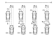
例えば、図3に示すように、自車両CSの前方に先行車両PVがある状況で、自車両CSの車幅(判定範囲)と先行車両PVの物体幅とがオーバーラップしている場合には、そのラップ率RRに応じて衝突の危険性が変化する。すなわち、図3では、自車両CSと先行車両PVとのラップ率RRが小さくなるほど(紙面左側となるほど)、衝突の危険性が低下する。一方、自車両CSと先行車両PVとのラップ率RRが大きくなるほど、衝突の危険性が増加する。 For example, as shown in FIG. 3, when the vehicle width (judgment range) of the host vehicle CS and the object width of the preceding vehicle PV overlap in a situation where the preceding vehicle PV is in front of the host vehicle CS. The risk of collision changes according to the lap rate RR. That is, in FIG. 3, the risk of collision decreases as the lap ratio RR between the host vehicle CS and the preceding vehicle PV decreases (to the left in the drawing). On the other hand, as the lap ratio RR between the host vehicle CS and the preceding vehicle PV increases, the risk of collision increases.
タイミング設定部25は、重なり率算出部24により算出されたラップ率に基づいて、衝突回避制御の作動タイミングを設定する。本実施形態では、ラップ率に応じて作動閾値を設定し、この作動閾値より、衝突回避制御の作動タイミングを設定する。具体的には、ラップ率が小さく衝突の危険性が低くなるほど運転者の回避操作のタイミングに急を要しないため、ラップ率が小さい程、作動閾値が大きく設定されている。一方、ラップ率が大きく衝突の危険性が高くなるほど運転者の回避操作のタイミングに急を要するため、ラップ率が大きい程、作動閾値が小さく設定されている。
The
制御部26は、自車前方の物体との衝突を回避するための衝突回避制御を実施する。制御部26は、タイミング設定部25により設定された作動閾値と衝突余裕時間(Time to Collision)を比較し、TTCが作動閾値よりも大きい場合、衝突回避制御を実施する。TTCとは、このままの自車速度で走行した場合に、何秒後に物体に衝突するかを示す評価値である。
The
運転支援装置40は、ドライバに対して警報音を発する警報装置や、自車両の車速を減速させるブレーキ装置であり、物体が自車両に衝突する可能性がある場合に、物体との衝突を回避するための各種動作を行う。運転支援装置40がブレーキ装置であれば、TTCが作動閾値よりも短い場合に、自動ブレーキを作動させる。また、運転支援装置40が警報装置であれば、TTCが作動閾値よりも短い場合に、警報音を発する。
The driving
ところで、自車前方の物体から検出された物体幅に誤差が生じている場合、ECU20が算出するラップ率が変化することとなる。図4では、走路上に自車両CSと先行車両PVとが存在しており、自車両CSの進行方向に対して先行車両PVの姿勢がX軸方向に傾いた状態が示されている。先行車両PVの背面のX軸方向での大きさを物体幅Wとして算出する場合、ECU20は、先行車両の向きが自車両の進行方向から所定角度だけ傾くことで物体幅を真値と比べて大きく算出してしまう場合がある。
By the way, when an error occurs in the object width detected from the object in front of the own vehicle, the lap ratio calculated by the
図4の例では、ECU20が、撮像画像から先行車両PVの側面の一部を含む領域を物体幅W2として算出することで、物体幅W2が先行車両PVの実際の物体幅W1よりも大きくなっている。例えば、先行車両の側面において、エッジ点を形成する特徴的な模様や形状等が存在することで、ECU20は側面を含む領域を物体幅Wとして誤検出する場合がある。これ以外にも、ブレーキ灯の点灯時において、ブレーキ灯の周囲で膨張する光を含む領域を物体の背面としてECU20が認識する場合、ECU20は、物体幅を実際の先行車両の背面の長さよりも大きく算出する場合がある。
In the example of FIG. 4, the
物体幅Wが大きく検出されることで、ラップ率が増加し、衝突回避制御の作動タイミングの設定に影響を与える場合がある。例えば、作動閾値が変更されることで、実際には自車両に衝突する危険が低い物体に対して、衝突回避制御の作動タイミングを早めてしまうおそれがある。その結果、衝突回避制御の不要作動の要因となる場合がある。そこで、本実施形態では、タイミング設定部25は、物体幅が所定閾値よりも小さい場合に、物体幅が所定閾値よりも大きい場合と比べて物体幅を小さくすることで、衝突判定における物体幅の誤差の影響を低減し、衝突回避制御の作動タイミングを適正に設定できるようにしている。
When the object width W is detected to be large, the lap ratio increases, which may affect the setting of the operation timing of the collision avoidance control. For example, when the operation threshold is changed, there is a possibility that the operation timing of the collision avoidance control may be advanced for an object that is actually less likely to collide with the host vehicle. As a result, unnecessary operation of the collision avoidance control may be caused. Thus, in the present embodiment, the
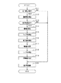
次に、ECU20より実施される物体の車両制御方法を、図5を用いて説明する。図5に示す処理は、ECU20により所定周期で実施される。また、この例では、自車前方に位置する先行車両を検出対象とする例を説明する。
Next, a vehicle control method for an object performed by the
ステップS11では、物体の同一判定を行う。本実施形態では、ECU20は、第1位置に応じて設定された画像探索範囲と、第2位置に応じて設定された電磁波探索範囲とに重なる領域が存在する場合に、画像物標と電磁波物標とを同一物体と判定する。ステップS11が物体認識工程として機能する。
In step S11, the same determination of the object is performed. In the present embodiment, when there is an area that overlaps the image search range set according to the first position and the electromagnetic wave search range set according to the second position, the
物体が同一と判定された場合(ステップS11:YES)、ステップS12に進む。一方、物体が同一と判定されない場合(ステップS11:NO)、図5の処理を一旦終了する。 When it is determined that the objects are the same (step S11: YES), the process proceeds to step S12. On the other hand, when the objects are not determined to be the same (step S11: NO), the processing in FIG.
ステップS12では、ステップS11で実施した同一判定の継続回数をカウントする。
同一判定の継続回数は、ステップS11により、画像物標と電磁波物標とを同一物体と判定した回数を示している。本実施形態では、ECU20は、前回同一と判定した画像物標と、今回同一と判定した画像物標との撮像画像上での類似度を用いて、同一の物体に対して同一判定を継続しているか否かを判定する。
In step S12, the number of continuations of the same determination performed in step S11 is counted.
The continuation number of the same determination indicates the number of times that the image target and the electromagnetic wave target are determined to be the same object in step S11. In the present embodiment, the
ステップS13では、物体と自車両との衝突可能性を判定する。衝突可能性がないと判定した場合(ステップS13:NO)、図5の処理を一旦終了する。一方、衝突する可能性があると判定した場合(ステップS13:YES)、ステップS14に進む。ステップS13が衝突判定工程として機能する。 In step S13, the possibility of collision between the object and the host vehicle is determined. If it is determined that there is no possibility of collision (step S13: NO), the processing in FIG. On the other hand, when it is determined that there is a possibility of collision (step S13: YES), the process proceeds to step S14. Step S13 functions as a collision determination step.
ステップS14では、撮像画像に含まれる先行車両から物体幅を算出する。本実施形態では、ECU20は、先行車両の背面を認識する辞書を用いて先行車両のX軸方向での大きさを示す物体幅を算出する。ステップS14が横幅算出工程として機能する。
In step S14, the object width is calculated from the preceding vehicle included in the captured image. In the present embodiment, the
ステップS15では、ステップS14で算出した物体幅を用いてラップ率を算出する。ECU20は、上記式(1)を用いてラップ率を算出する。ステップS15が重なり率算出工程として機能する。
In step S15, the lap ratio is calculated using the object width calculated in step S14. The
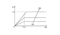
ステップS16では、物体幅を元の物体幅から変更するための補正係数Coを算出する。図6は、横軸をラップ率RRとして、縦軸を補正係数Coとしたグラフである。本実施形態では、補正係数Coは、元の物体幅からの縮小倍率を示す0以上1以下の値として規定されている。また、補正係数Coは、ラップ率が閾値Th1よりも小さい範囲において、ラップ率が減少する程、元の物体幅に対する縮小倍率が小さくなるようその値が規定されている。また、閾値Th1よりも大きい範囲では、ラップ率が増加しても値が一定となるよう規定されている。本実施形態では、ECU20は、図6に示すラップ率RRと補正係数Coとの関係性を規定したマップを記録しており、このマップを参照することで補正係数Coを算出する。
In step S16, a correction coefficient Co for changing the object width from the original object width is calculated. FIG. 6 is a graph in which the horizontal axis represents the lap ratio RR and the vertical axis represents the correction coefficient Co. In the present embodiment, the correction coefficient Co is defined as a value from 0 to 1 indicating a reduction magnification from the original object width. The value of the correction coefficient Co is defined such that the reduction ratio with respect to the original object width becomes smaller as the wrap ratio decreases in a range where the wrap ratio is smaller than the threshold Th1. Further, in a range larger than the threshold Th1, the value is defined to be constant even if the lap rate increases. In the present embodiment, the
閾値Th1は、物体幅の誤差が生じた場合に、ラップ率がばらつくことで作動閾値の設定に影響を与える可能性が高いラップ率の値に基づいて設定されている。本実施形態では、先行車両と自車両とがX軸方向でぶつからない位置関係にある場合に、物体幅が大きく算出されてしまうことで衝突回避制御の不要作動が生じる可能性のある物体幅に基づいて閾値Th1を設定している。言い換えれば、先行車両における自車両側の側面のX軸方向での位置と、自車両における先行車両側の側面のX軸方向での位置とが一致する場合に、先行車両の物体幅が真値と比べて大きく算出されることで衝突回避制御の不要作動が生じる可能性がある場合のラップ率に基づいて閾値Th1を設定している。一例として、閾値Th1として、0%以上、20%以下のラップ率を用いている。 The threshold value Th1 is set based on a value of the lap rate that is likely to affect the setting of the operation threshold value due to a variation in the lap rate when an error in the object width occurs. In the present embodiment, when the preceding vehicle and the host vehicle are in a positional relationship where they do not collide with each other in the X-axis direction, the object width is calculated to be large, so that an unnecessary operation of the collision avoidance control may occur. The threshold Th1 is set based on the threshold Th1. In other words, when the position of the side surface of the preceding vehicle in the X-axis direction on the side of the host vehicle coincides with the position of the side surface of the host vehicle in the X-axis direction, the object width of the preceding vehicle becomes a true value. The threshold value Th1 is set based on the lap ratio in a case where the unnecessary operation of the collision avoidance control is likely to occur due to being calculated larger than. As an example, a lap ratio of 0% or more and 20% or less is used as the threshold Th1.
また、同一判定してまもない期間では、ECU20の同一判定の信頼度が低く、物体幅の誤差が大きくなるおそれがある。そのため、ECU20は、ステップS12で取得した同一判定の継続回数Nが増加するに従い、元の物体幅からの縮小倍率が大きくなるよう補正係数Coを算出する。図6では、ラップ率が閾値Th1以上となる場合でも、同一判定の継続回数Nが少なく程、変更後の物体幅が元の物体幅よりも小さくなるよう補正係数Coが規定されている。
Further, during a period immediately after the same determination is made, the reliability of the same determination by the
ステップS17では、ステップS16で算出した補正係数を用いて物体幅を変更する。ECU20は、下記式(2)を用いて、物体幅を変更する。
Wad=WO×Ad … (2)
なお、WOは、ステップS14で算出した元の物体幅である。Wadは、補正後の物体幅を示す。Adは、補正係数を示す。
In step S17, the object width is changed using the correction coefficient calculated in step S16. The
Wad = WO × Ad (2)
Note that WO is the original object width calculated in step S14. Wad indicates the corrected object width. Ad indicates a correction coefficient.
図7は、変更前の物体幅を示し、図8は、変更後の物体幅を示している。なお、図7,図8では、説明を容易にするため、物体幅の変更対象となるラップ率を実際のものと比べて大きく示している。本実施形態では、ECU20は、ステップS16で算出された補正係数に応じて先行車両の物体幅をX軸方向での中心位置Mを基準として左右それぞれに均等に縮小している。無論、これ以外にも、ECU20は、自車両に近い側の物体幅のみを縮小するものであってもよい。
FIG. 7 shows the object width before the change, and FIG. 8 shows the object width after the change. In FIGS. 7 and 8, the lap ratio for which the object width is changed is shown larger than the actual lap ratio for the sake of simplicity. In the present embodiment, the
ステップS18では、補正後の物体幅を用いて、ラップ率を算出する。ECU20は、ステップS17における変更後の物体幅Wadと、判定範囲とを用いて上記式(1)によりラップ率RRを算出する。本実施形態では、まず、ECU20は、変更後の物体幅Wadを、先行車両の中心位置を基準として左右に延びる横幅範囲として設定する。そして、物体幅Wadを用いて設定された横幅範囲の内、X軸方向において判定範囲の左端位置と右端位置とに含まれる長さを重なる長さWorとして算出する。また、ECU20は、先行車両の横方向(X軸方向)での中心位置を、ステップS11の同一判定に応じて算出された融合位置により算出する。
In step S18, the lap ratio is calculated using the corrected object width. The
ステップS19では、ステップS18で算出したラップ率を用いて作動閾値を算出する。作動閾値は、ラップ率が小さくなる程、衝突回避制御の作動タイミングが遅くなるようその値が設定されている。ステップS16〜S19がタイミング設定工程として機能する。 In step S19, an operation threshold is calculated using the lap ratio calculated in step S18. The operation threshold value is set so that the operation timing of the collision avoidance control is delayed as the lap ratio decreases. Steps S16 to S19 function as a timing setting step.
ステップS20では、ステップS19で算出した作動閾値を用いて、衝突回避制御を実施する。具体的には、ECU20は、先行車両に対するTTCを算出し、この衝突余裕時間を作動閾値と比較する。そして、TTCが作動閾値よりも小さい場合、運転支援装置40に自動ブレーキを実施させる。
In step S20, collision avoidance control is performed using the operation threshold value calculated in step S19. Specifically, the
以上詳述した本実施形態によれば、以下の優れた効果が得られる。 According to the embodiment described above, the following excellent effects can be obtained.
ECU20は、ラップ率が作動閾値よりも小さい場合に、ラップ率が作動閾値よりも大きい場合と比べて物体幅が小さくなるよう当該物体幅を変更する。そして、変更された物体幅と判定範囲との新たな重なり率を算出し、算出した新たな重なり率に基づいて、物体との衝突を回避するための自車両に対する衝突回避制御の作動タイミングを設定することとした。この場合、物体幅の誤差の影響を受け易いラップ率と誤差の影響を受けにくいラップ率とを閾値により区別し、閾値以下のラップでは物体幅を小さくする。また、物体幅の誤差の影響を受けにくい閾値以上のラップ率では、物体幅を変更しないことで、元のラップ率に応じた作動タイミングの設定を優先する。このため、衝突回避制御の作動タイミングに対する物体幅の誤差の影響を抑制することで、衝突回避制御を適正なタイミングで実施することができる。
The
自車前方の物体を同一物体として判定したことを条件に、この物体との衝突判定を行う場合、同一判定してまもない期間では、物体の同一判定の信頼度が低く、物体幅の誤差が大きくなる場合がある。この点、ECU20は、同一判定の継続回数が増加する程、物体幅の縮小倍率を大きくする、こととした。この場合、同一判定の信頼度が低い期間においては、物体幅を小さめに算出することで、誤判定時の物体に対する不要作動を防止することができる。一方、同一判定の信頼度が高い期間においては、物体幅の縮小倍率を大きくすることで、ラップ率の算出精度を優先させることができ、衝突判定の判定精度を高めることができる。
When a collision determination with an object in front of the own vehicle is performed under the condition that the same object is determined, the reliability of the same determination of the object is low during a period immediately after the determination of the same, and an error in the object width. May be large. In this regard, the
ECU20は、同一判定の継続回数が増加しても、算出したラップ率が閾値Th1以下の場合は、変更後の物体幅が元の物体幅よりも大きくならないように縮小倍率を変更する。この場合、継続回数の増加に応じて、物体幅が元の物体幅よりも大きくなるのを防止することができ、ラップ率を適正に算出することができる。
If the calculated lap ratio is equal to or smaller than the threshold Th1 even if the number of continuations of the same determination increases, the
(第2実施形態)
この第2実施形態では、第1実施形態と異なる構成を中心に説明を行う。この第2実施形態では、ECU20は、同一判定の継続回数の増加に応じた元の物体幅からの縮小倍率の増加速度をラップ率が小さい程遅くする。
(2nd Embodiment)
In the second embodiment, a description will be given focusing on a configuration different from the first embodiment. In the second embodiment, the
まずは、第2実施形態にかかる補正係数Coを、図9を用いて説明する。図9は、横軸を幅係数インデックスIn_wとして、縦軸を補正係数Coとしたグラフを示している。本実施形態では、ECU20は、図9に示す幅係数インデックスIn_wと補正係数Coとの関係性を規定したマップを記録しており、ラップ率に応じて幅係数インデックスIn_wを変更させることでマップ上の補正係数Coを算出する。
First, a correction coefficient Co according to the second embodiment will be described with reference to FIG. FIG. 9 shows a graph in which the horizontal axis is the width coefficient index In_w and the vertical axis is the correction coefficient Co. In the present embodiment, the
幅係数インデックスIn_wは、補正係数Coの参照位置を決定するための値であり、同一判定の継続回数の増加に応じて増加する値である。そのため、継続回数が増加するに従い、幅係数インデックスIn_wが増加し、算出される補正係数Coが大きくなる。 The width coefficient index In_w is a value for determining the reference position of the correction coefficient Co, and is a value that increases as the number of continuations of the same determination increases. Therefore, as the continuation number increases, the width coefficient index In_w increases, and the calculated correction coefficient Co increases.
補正係数Coは、幅係数インデックスIn_wが閾値Th2よりも小さい範囲において、元の物体幅からの縮小倍率が小さくようその値が規定されている。また、補正係数Coは、閾値Th2よりも大きい範囲では、幅係数インデックスIn_wが増加しても値が一定となるよう規定されている。 The value of the correction coefficient Co is defined such that the reduction magnification from the original object width is small in a range where the width coefficient index In_w is smaller than the threshold Th2. Further, the correction coefficient Co is defined to be constant in a range larger than the threshold value Th2 even if the width coefficient index In_w increases.
図10は、第2実施形態において、図6のステップS16の処理を説明するフローチャートである。この実施形態においても、同一判定の継続回数が増加する毎に物体幅を変更する例を説明する。 FIG. 10 is a flowchart illustrating the process of step S16 in FIG. 6 in the second embodiment. Also in this embodiment, an example will be described in which the object width is changed each time the number of continuations of the same determination increases.
まず、ステップS31では、ラップ率に応じてインデックス加算値を算出する。インデックス加算値は、継続回数の増加に応じた幅係数インデックスの増加分を示す値である。そのため、インデックス加算値が小さい程、幅係数インデックスの増加分が少なくなり、補正係数の増加速度が遅くなる。また、インデックス加算値が大きくなる程、幅係数インデックスの増加分が多くなり、補正係数の増加速度が速くなる。 First, in step S31, an index addition value is calculated according to the lap rate. The index addition value is a value indicating an increase in the width coefficient index according to an increase in the number of continuations. Therefore, the smaller the index addition value, the smaller the increase in the width coefficient index, and the slower the correction coefficient increases. Also, as the index addition value increases, the increase in the width coefficient index increases, and the rate of increase of the correction coefficient increases.
図11は、横軸をラップ率RRとし、縦軸をインデックス加算値Addとするグラフである。図11に示すインデックス加算値Addは、ラップ率RRが小さい程小さな値となるよう規定されている。言い換えれば、ラップ率RRが小さい程、物体幅の縮小倍率を示す補正係数Coの増加速度が遅くなる。また、ラップ率RRが0からR1までの範囲では、値が一定であり、R1からR2までの範囲ではラップ率RRの増加に応じて値が単調増加する。そして、ラップ率RRがR2以上の範囲では、値が一定値となっている。 FIG. 11 is a graph in which the horizontal axis represents the lap ratio RR and the vertical axis represents the index addition value Add. The index addition value Add shown in FIG. 11 is defined to be smaller as the lap ratio RR is smaller. In other words, the smaller the lap ratio RR, the slower the rate of increase of the correction coefficient Co indicating the reduction ratio of the object width. The value is constant when the lap rate RR is in the range from 0 to R1, and monotonically increases in the range from R1 to R2 as the lap rate RR increases. Then, when the lap ratio RR is equal to or more than R2, the value is a constant value.
ステップS32では、ステップS31で算出したインデックス加算値Addを用いて幅係数インデックスIn_wを算出する。ECU20は、下記式(3)を用いて、幅係数インデックスIn_wを算出する。
In_w(i)=In_w(i−1)+Add … (3)
ここで、iは、物体の同一判定の継続回数を示し、1以上の整数である。また、In_w(i)は、同一判定がi回継続された場合に算出される幅係数インデックスを示す。
In step S32, the width coefficient index In_w is calculated using the index addition value Add calculated in step S31. The
In_w (i) = In_w (i-1) + Add (3)
Here, i indicates the number of continuations of the same determination of the object, and is an integer of 1 or more. In_w (i) indicates a width coefficient index calculated when the same determination is continued i times.
そのため、図9に示すように、n−1番目の幅係数インデックスIn_w(n−1)の位置から、n番目の幅係数インデックスIn_w(n)までの増加分Δwはラップ率に応じて算出されたインデックス加算値Addとなる。ここで、補正係数Coの増加速度は、前回のインデックス加算値から今回のインデックス加算値までの幅により規定されるため、ラップ率に応じて、補正係数Coの増加速度が決定されることとなる。 Therefore, as shown in FIG. 9, the increase Δw from the position of the (n−1) th width coefficient index In_w (n−1) to the nth width coefficient index In_w (n) is calculated according to the wrap rate. It becomes the index addition value Add. Here, since the increasing speed of the correction coefficient Co is defined by the width from the previous index added value to the current index added value, the increasing speed of the correction coefficient Co is determined according to the lap rate. .
ステップS33では、ステップS32で算出した幅係数インデックスに対応する補正値を算出する。本実施形態では、ECU20は、ステップS32で算出した幅係数インデックスに対応する補正係数を図9に示すマップを用いて算出する。
In step S33, a correction value corresponding to the width coefficient index calculated in step S32 is calculated. In the present embodiment, the
ステップS33の処理が終了すると、図5のステップS17では、算出した補正係数を用いて、物体幅Wを補正する。 When the processing in step S33 ends, in step S17 in FIG. 5, the object width W is corrected using the calculated correction coefficient.
以上詳述した本実施形態によれば、以下の優れた効果が得られる。 According to the embodiment described above, the following excellent effects can be obtained.
ECU20は、同一判定の継続回数の増加に応じた元の物体幅からの縮小倍率の増加分をラップ率に基づいて算出するものであり、縮小倍率の増加速度をラップ率が小さい程遅くする。この場合、ラップ率が小さい場合は、継続回数の増加に応じた補正係数の増加速度をラップ率が大きい場合と比べて遅くすることで、物体幅の誤差の影響を低減することができる。また、補正係数を算出するための1つのマップにより、継続回数の増加に応じた補正係数を算出することができるため、ECU20が必要とするメモリ容量を低減することができる。
The
(第3実施形態)
この第3実施形態では、第2実施形態と異なる構成を中心に説明する。この第3実施形態では、自車両から先行車両までの横方向(車幅方向)での距離が大きくなる状況下であると判定した場合に、自車両から先行車両までの横方向での距離が大きくなる状況下であると判定しない場合と比べて物体幅を小さくする。ここで、自車両から先行車両までの横方向での距離が大きくなる状況下とは、先行車両が自車両から横方向に遠ざかる場合や、自車両が先行車両から横方向に遠ざかる場合のいずれをも含んでいる。
(Third embodiment)
In the third embodiment, a configuration different from that of the second embodiment will be mainly described. In the third embodiment, when it is determined that the distance in the lateral direction (vehicle width direction) from the own vehicle to the preceding vehicle is large, the lateral distance from the own vehicle to the preceding vehicle is determined. The object width is reduced as compared with the case where it is not determined that the object is in a situation where the object becomes large. Here, the situation in which the distance in the lateral direction from the own vehicle to the preceding vehicle is large means that the preceding vehicle moves away from the own vehicle in the horizontal direction or the own vehicle moves away from the preceding vehicle in the horizontal direction. Also included.
図12は、第3実施形態において、ECU20が実施する処理を説明するフローチャートである。ECU20は、図12に示す処理を所定周期で実施する。
FIG. 12 is a flowchart illustrating a process performed by the
ステップS41では、自車両から先行車両までの横方向での距離が大きくなる状況下であるか否かを判定する。ECU20は、ヨーレートセンサ33からの出力に応じた自車両の横方向での位置の変化の検出と、撮像画像上での先行車両の位置の変化の検出とを組み合わせることで、自車両から先行車両までの横方向での距離が大きくなる状況下であるか否かを判定する。ステップS41が状況判定部として機能する。
In step S41, it is determined whether or not the situation is such that the lateral distance from the host vehicle to the preceding vehicle increases. The
例えば、ECU20は、ヨーレートセンサ33の出力により自車両が直進していると判定でき、かつ先行車両のウィンカーの点灯を検出した場合、図13に示すように、近い将来において先行車両が右左折することで、自車両から先行車両までの横方向での距離が大きくなる状況下であると判定する。また、ECU20は、ヨーレートセンサ33の出力により、自車両が横方向に旋回していると判定でき、かつ、撮像画像上での先行車両の位置が横方向に変化している場合、図14に示すように、自車両が右左折することで、自車両から先行車両までの横方向での距離が大きくなる状況下であると判定する。
For example, when the
なお、先行車両が停止していると判定し、かつ、区画線の曲率変化が大きいと判定した場合、自車両がカーブ路を走行中であるとして、自車両から先行車両までの横方向での距離が大きくなる状況下であると判定するものであってもよい。 When it is determined that the preceding vehicle is stopped and that the change in the curvature of the lane marking is large, it is determined that the own vehicle is traveling on a curved road, and the vehicle is traveling in a lateral direction from the own vehicle to the preceding vehicle. It may be determined that the distance is large.
自車両から先行車両までの横方向での距離が大きくなる状況下であると判定した場合(ステップS42:YES)、ステップS43では、幅係数インデックスを現在の値よりも小さくする。そのため、継続回数の増加に応じた補正係数の増加速度が、自車両から先行車両までの横方向での距離が大きくなる状況下であると判定しない場合と比べて遅くなる。その結果、補正係数が小さい値に維持されやすくなり、物体幅が大きくなりにくくなる。 When it is determined that the distance in the lateral direction from the own vehicle to the preceding vehicle is large (step S42: YES), in step S43, the width coefficient index is set smaller than the current value. Therefore, the rate of increase of the correction coefficient in accordance with the increase in the number of continuations becomes slower than when it is not determined that the distance between the host vehicle and the preceding vehicle in the lateral direction increases. As a result, the correction coefficient is easily maintained at a small value, and the object width is less likely to be increased.
一方、自車両から先行車両までの横方向での距離が大きくなる状況下であると判定されない場合(ステップS42:NO)、図12に示す処理を一旦終了する。 On the other hand, when it is not determined that the vehicle is in a situation where the distance in the lateral direction from the own vehicle to the preceding vehicle increases (step S42: NO), the process illustrated in FIG.
以上詳述した本実施形態によれば、以下の優れた効果が得られる。 According to the embodiment described above, the following excellent effects can be obtained.
自車両から先行車両までの横方向での距離が大きくなる状況下では、先行車両と自車両とが同一方向に移動している場合と比べて、衝突の可能性が低くなる。この点、上記構成では、ECU20は、自車両から先行車両までの横方向での距離が大きくなる状況下であると判定した場合に、自車両から先行車両までの横方向での距離が大きくなる状況下であると判定しない場合と比べて物体幅を小さくする、こととした。この場合、先行車両と自車両とが衝突する可能性が低い場合は物体幅を小さくすることで、衝突回避制御の作動タイミングを遅くし、衝突回避制御の不要作動を抑制することができる。
In a situation where the distance between the host vehicle and the preceding vehicle in the lateral direction is large, the possibility of collision is lower than when the preceding vehicle and the host vehicle are moving in the same direction. In this regard, in the above configuration, the
(第4実施形態)
この第4実施形態では、第1〜第3実施形態と異なる構成を中心に説明する。
(Fourth embodiment)
In the fourth embodiment, a description will be given focusing on a configuration different from the first to third embodiments.
この第4実施形態では、ECU20は、ラップ率が所定閾値Th1よりも小さい場合に、物体幅を同じ縮小倍率で小さくする。図15は、第4実施形態において、横軸をラップ率RRとし縦軸を補正係数Coとしたグラフである。補正係数Coは、ラップ率が閾値Th1よりも小さい範囲において、元の物体幅からの縮小倍率が同じ値となるようその値が規定されている。
In the fourth embodiment, when the lap ratio is smaller than the predetermined threshold Th1, the
そのため、図5のステップS16では、ECU20は、図15に示すマップを参照することで、補正係数Coを算出する。
Therefore, in step S16 in FIG. 5, the
(その他の実施形態)
・車両制御装置は、画像センサ32の検出結果を用いて、物体と自車両との衝突を判定するものであってもよい。この場合、車両制御装置は、画像センサ32のみを備える構成となる。
(Other embodiments)
The vehicle control device may determine the collision between the object and the own vehicle using the detection result of the
・第3実施形態において、ECU20は、ステップS41において、周知のオプティカルフローを用いて、自車両から先行車両までの横方向での距離が大きくなる状況下であるか否かを判定してもよい。オプティカルフローは、撮像画像において、先行車両に対応する画素のベクトル場を示している。横方向での相対位置の変化は、先行車両のオプティカルフローにおいて、横方向において自車両と反対側に延びるベクトルの大きさとして算出される。そのため、ECU20は、このベクトルの大きさを閾値と比較することで、自車両から先行車両までの横方向での距離が大きくなる状況下であるか否かを判定する。
In the third embodiment, in step S41, the
・物体が同一であるか否かの判定方法として、以下のものを採用するものであってもよい。第1位置に基づいて、電磁波物標が自車両と衝突するまでの余裕時間としてTTCを算出し、かつ第2位置に基づいて、画像物標が自車両と衝突するまでの余裕時間を算出する。そして、図5のステップS11において、算出された各TTCの差が閾値以下である場合に、電磁波物標と画像物標とを同一物体として判定する。また、ステップS11において、各TTCの差が閾値以下であることと、電磁波探索範囲と画像探索範囲との間に重なる範囲が存在することの両条件を、物体が同一であることの判定条件とするものであってもよい。 The following method may be adopted as a method for determining whether or not the objects are the same. Based on the first position, TTC is calculated as a margin time until the electromagnetic wave target collides with the host vehicle, and a margin time until the image target collides with the host vehicle is calculated based on the second position. . Then, in step S11 of FIG. 5, when the calculated difference between the TTCs is equal to or smaller than the threshold, the electromagnetic wave target and the image target are determined as the same object. Further, in step S11, the two conditions that the difference between the TTCs is equal to or smaller than the threshold value and that there is an overlapping range between the electromagnetic wave search range and the image search range are the same as the determination condition that the objects are the same. May be used.
同一判定の継続回数の増加に応じた補正係数の変更頻度は、継続回数の増加毎以外にも、継続回数の増加が複数回に達した場合に、補正係数を変更するものであってもよい。 The change frequency of the correction coefficient according to the increase in the number of continuations of the same determination may be such that the correction coefficient is changed when the number of continuations reaches a plurality of times, in addition to every increase in the number of continuations. .
・物体幅を算出する物体として、車両に代えて、歩行者や二輪車を対象とするものであってもよい。
・ECU20は、ラップ率に応じて作動閾値を変更することに加えて、ラップ率に応じて衝突回避制御の各動作の強度を変更するものであってもよい。この場合、ECU20は、ラップ率が減少する程、自動ブレーキの制動力を弱くし、また、警報音の音量を小さくする。
The object for calculating the object width may be a pedestrian or a motorcycle instead of a vehicle.
-In addition to changing the operation threshold value according to the lap rate, the
20…車両制御装置としてのECU、21…物体認識部、22…衝突判定部、23…横幅算出部、24…重なり率算出部、25…タイミング設定部、32…画像センサ。 20: ECU as a vehicle control device, 21: object recognition unit, 22: collision determination unit, 23: width calculation unit, 24: overlap ratio calculation unit, 25: timing setting unit, 32: image sensor.
Claims (7)
少なくとも、自車前方を画像センサ(32)により撮像した撮像画像に基づいて、前記物体の位置を認識する物体認識部(21)と、
前記位置が認識された物体と自車両との衝突可能性を判定する衝突判定部(22)と、
前記物体と自車両とが衝突する可能性があると判定された場合に、前記撮像画像に基づいて、物体の横方向での大きさを示す物体幅を算出する横幅算出部(23)と、
自車両の前方に仮想的に設定された判定範囲と算出された前記物体幅との横方向での重なり量の割合を示す重なり率を算出する重なり率算出部(24)と、
算出された前記重なり率に基づいて、前記衝突回避制御の作動タイミングを設定するタイミング設定部(25)と、を備え、
前記タイミング設定部は、前記重なり率が所定閾値よりも小さい場合に、前記重なり率が前記所定閾値よりも大きい場合と比べて前記物体幅が小さくなるよう当該物体幅を変更し、変更後の前記物体幅と前記判定範囲とで算出した新たな重なり率に基づいて、前記衝突回避制御の作動タイミングを設定する、車両制御装置。 A vehicle control device (20) for performing collision avoidance control for avoiding a collision with an object (PV) in front of a vehicle (CS),
At least an object recognizing unit (21) for recognizing a position of the object based on a captured image obtained by capturing an image of the front of the vehicle by an image sensor (32);
A collision determining unit (22) for determining a possibility of collision between the object whose position is recognized and the host vehicle;
When it is determined that there is a possibility that the object and the host vehicle collide, a width calculation unit (23) that calculates an object width indicating a size of the object in a horizontal direction based on the captured image;
An overlap ratio calculation unit (24) for calculating an overlap ratio indicating a ratio of a lateral overlap amount between the determination range virtually set in front of the host vehicle and the calculated object width;
A timing setting unit (25) for setting an operation timing of the collision avoidance control based on the calculated overlap ratio;
The timing setting unit, when the overlap rate is smaller than a predetermined threshold, changes the object width so that the object width is smaller than when the overlap rate is larger than the predetermined threshold, and the changed A vehicle control device that sets an operation timing of the collision avoidance control based on a new overlap ratio calculated based on an object width and the determination range.
前記タイミング設定部は、前記物体の同一判定の継続回数が増加するに従い、前記物体幅を変更する際の元の物体幅に対する縮小倍率を変更するものであって、
前記同一判定の継続回数が増加する程、前記縮小倍率を大きくする、請求項1又は請求項2に記載の車両制御装置。 The object recognizing unit uses the position of the object detected based on the captured image of the front of the vehicle by the image sensor and the position of the object detected by the electromagnetic wave sensor (31) to determine whether the object is the same object. Determine whether there is, to recognize the position of the object based on the determination result,
The timing setting unit, as the number of continuations of the same determination of the object increases, to change the reduction magnification with respect to the original object width when changing the object width,
3. The vehicle control device according to claim 1, wherein the reduction ratio is increased as the number of continuations of the same determination increases. 4.
前記重なり率が小さい程、前記縮小倍率の増加速度が遅くなるよう前記縮小倍率の増加分を算出する、請求項3又は請求項4に記載の車両制御装置。 The timing setting unit is configured to calculate an increasing speed of a reduction magnification from the original object width according to the increase in the number of continuations based on the overlap rate,
5. The vehicle control device according to claim 3, wherein an increase in the reduction ratio is calculated such that an increasing speed of the reduction ratio is slower as the overlap ratio is smaller.
前記タイミング設定部は、前記物体から自車両までの横方向での距離が大きくなる状況下であると判定された場合に、前記物体から自車両までの横方向での距離が大きくなる状況下であると判定されない場合と比べて前記物体幅を小さくする、請求項1から請求項5のいずれか一項に記載の車両制御装置。 A situation determination unit that determines whether the distance in the lateral direction from the object to the own vehicle is large or not,
The timing setting unit, under the situation where the distance in the lateral direction from the object to the host vehicle is determined to be large under the condition that the distance in the lateral direction from the object to the host vehicle is large. The vehicle control device according to any one of claims 1 to 5, wherein the object width is reduced as compared with a case where it is not determined that there is a vehicle.
少なくとも、自車前方を画像センサにより撮像した撮像画像に基づいて、前記物体の位置を認識する物体認識工程と、
前記位置が認識された物体と自車両との衝突可能性を判定する衝突判定工程と、
前記物体と自車両とが衝突する可能性があると判定された場合に、前記撮像画像に基づいて、物体の横方向での大きさを示す物体幅を算出する横幅算出工程と、
自車両の前方に仮想的に設定された判定範囲と算出された前記物体幅との横方向での重なり量の割合を示す重なり率を算出する重なり率算出工程と、
算出された前記重なり率に基づいて、前記衝突回避制御の作動タイミングを設定するタイミング設定工程と、を備え、
前記タイミング設定工程では、前記重なり率が所定閾値よりも小さい場合に、前記重なり率が前記所定閾値よりも大きい場合と比べて前記物体幅が小さくなるよう当該物体幅を変更し、変更後の前記物体幅と前記判定範囲とで算出した新たな重なり率に基づいて、前記衝突回避制御の作動タイミングを設定する、車両制御方法。 A vehicle control method for performing collision avoidance control for avoiding a collision with an object ahead of the own vehicle,
At least, an object recognition step of recognizing the position of the object based on an image captured by an image sensor in front of the vehicle,
A collision determination step of determining the possibility of collision between the object whose position is recognized and the host vehicle,
When it is determined that there is a possibility of collision between the object and the host vehicle, based on the captured image, a width calculation step of calculating an object width indicating the size of the object in the horizontal direction,
An overlap ratio calculation step of calculating an overlap ratio indicating a ratio of an overlap amount in a lateral direction between the determined object range and the calculated object width in front of the host vehicle,
A timing setting step of setting an operation timing of the collision avoidance control based on the calculated overlap ratio,
In the timing setting step, when the overlap rate is smaller than a predetermined threshold, the object width is changed such that the object width is smaller than when the overlap rate is larger than the predetermined threshold, and the changed A vehicle control method, wherein an operation timing of the collision avoidance control is set based on a new overlap ratio calculated based on an object width and the determination range.
Priority Applications (2)
| Application Number | Priority Date | Filing Date | Title |
|---|---|---|---|
| JP2016242667A JP6673178B2 (en) | 2016-12-14 | 2016-12-14 | Vehicle control device and vehicle control method |
| US15/839,657 US10569767B2 (en) | 2016-12-14 | 2017-12-12 | Vehicle control apparatus and vehicle control method |
Applications Claiming Priority (1)
| Application Number | Priority Date | Filing Date | Title |
|---|---|---|---|
| JP2016242667A JP6673178B2 (en) | 2016-12-14 | 2016-12-14 | Vehicle control device and vehicle control method |
Publications (2)
| Publication Number | Publication Date |
|---|---|
| JP2018097687A JP2018097687A (en) | 2018-06-21 |
| JP6673178B2 true JP6673178B2 (en) | 2020-03-25 |
Family
ID=62488264
Family Applications (1)
| Application Number | Title | Priority Date | Filing Date |
|---|---|---|---|
| JP2016242667A Active JP6673178B2 (en) | 2016-12-14 | 2016-12-14 | Vehicle control device and vehicle control method |
Country Status (2)
| Country | Link |
|---|---|
| US (1) | US10569767B2 (en) |
| JP (1) | JP6673178B2 (en) |
Families Citing this family (16)
| Publication number | Priority date | Publication date | Assignee | Title |
|---|---|---|---|---|
| JP6493280B2 (en) * | 2016-04-01 | 2019-04-03 | 株式会社デンソー | Object detection device and object detection method |
| JP6819281B2 (en) * | 2016-12-27 | 2021-01-27 | 株式会社デンソー | Collision detection device and collision detection system |
| KR20180099288A (en) * | 2017-02-28 | 2018-09-05 | 주식회사 만도 | System and Method for Intersection Collision prevention |
| KR20190080053A (en) * | 2017-12-28 | 2019-07-08 | 현대자동차주식회사 | the Guiding Apparatus for inertia driving and the Method the same |
| JP7067175B2 (en) * | 2018-03-23 | 2022-05-16 | 株式会社デンソー | Driving assistance devices, driving assistance methods, and computer programs |
| CN108944921B (en) * | 2018-07-03 | 2020-11-20 | 驭势(上海)汽车科技有限公司 | Method and device for longitudinal control of vehicle |
| US10829113B2 (en) | 2018-09-17 | 2020-11-10 | Ford Global Technologies, Llc | Vehicle collision avoidance |
| JP7275639B2 (en) | 2019-02-25 | 2023-05-18 | トヨタ自動車株式会社 | Driving support device |
| US11001200B2 (en) * | 2019-05-30 | 2021-05-11 | Nissan North America, Inc. | Vehicle occupant warning system |
| US11498554B2 (en) * | 2020-02-25 | 2022-11-15 | Ford Global Technologies, Llc | Enhanced object detection and response |
| JP7424878B2 (en) * | 2020-03-19 | 2024-01-30 | 本田技研工業株式会社 | Vehicle control equipment and vehicles |
| JP7216695B2 (en) * | 2020-11-04 | 2023-02-01 | 本田技研工業株式会社 | Surrounding vehicle monitoring device and surrounding vehicle monitoring method |
| KR20220065132A (en) * | 2020-11-12 | 2022-05-20 | 현대자동차주식회사 | Vehicle and controlling method of vehicle |
| US20220194424A1 (en) * | 2020-12-22 | 2022-06-23 | Waymo Llc | Autonomous vehicle trajectory computed using box-based probabilistic overlap model |
| JP2022122797A (en) * | 2021-02-10 | 2022-08-23 | 本田技研工業株式会社 | Yaw behavior estimation device |
| WO2024014049A1 (en) * | 2022-07-11 | 2024-01-18 | 日立Astemo株式会社 | Collision avoidance assistance device |
Family Cites Families (8)
| Publication number | Priority date | Publication date | Assignee | Title |
|---|---|---|---|---|
| JP4558758B2 (en) * | 2007-05-07 | 2010-10-06 | 三菱電機株式会社 | Obstacle recognition device for vehicles |
| JP5565017B2 (en) | 2010-03-18 | 2014-08-06 | トヨタ自動車株式会社 | Rear collision warning device and rear collision warning method |
| JP5962319B2 (en) | 2012-08-08 | 2016-08-03 | 株式会社デンソー | Vehicle control device |
| JP5873461B2 (en) * | 2013-07-03 | 2016-03-01 | 本田技研工業株式会社 | Vehicle control object determination device, vehicle control object determination method, and vehicle control object determination program |
| JP6453695B2 (en) * | 2015-03-31 | 2019-01-16 | 株式会社デンソー | Driving support device and driving support method |
| JP6384446B2 (en) * | 2015-10-14 | 2018-09-05 | 株式会社デンソー | Vehicle control apparatus and vehicle control method |
| JP6083482B2 (en) | 2016-03-07 | 2017-02-22 | 株式会社デンソー | Vehicle control device |
| JP6787102B2 (en) * | 2016-12-14 | 2020-11-18 | 株式会社デンソー | Object detection device, object detection method |
-
2016
- 2016-12-14 JP JP2016242667A patent/JP6673178B2/en active Active
-
2017
- 2017-12-12 US US15/839,657 patent/US10569767B2/en active Active
Also Published As
| Publication number | Publication date |
|---|---|
| US10569767B2 (en) | 2020-02-25 |
| US20180162392A1 (en) | 2018-06-14 |
| JP2018097687A (en) | 2018-06-21 |
Similar Documents
| Publication | Publication Date | Title |
|---|---|---|
| JP6673178B2 (en) | Vehicle control device and vehicle control method | |
| JP6614108B2 (en) | Vehicle control apparatus and vehicle control method | |
| CN107408345B (en) | Method and device for determining presence of target object | |
| JP6988200B2 (en) | Vehicle control device | |
| US10866316B2 (en) | Object detection apparatus and object detection method | |
| US10535264B2 (en) | Object detection apparatus and object detection method | |
| JP6855776B2 (en) | Object detection device and object detection method | |
| JP6443318B2 (en) | Object detection device | |
| JP6361592B2 (en) | Vehicle control device | |
| WO2018074288A1 (en) | Vehicle recognition device and vehicle recognition method | |
| WO2017104773A1 (en) | Moving body control device and moving body control method | |
| US20180297591A1 (en) | Vehicle control apparatus and vehicle control method | |
| JP2017010539A (en) | Vehicle control device and vehicle control method | |
| US20180182243A1 (en) | Object detection method and apparatus | |
| WO2017104503A1 (en) | Traveling-body control device and traveling-body control method | |
| JP6669090B2 (en) | Vehicle control device | |
| JP6747389B2 (en) | Collision estimating device and collision estimating method | |
| JP2019052920A (en) | Object detector, object detection method and vehicle control system | |
| WO2017138329A1 (en) | Collision prediction device | |
| WO2018070335A1 (en) | Movement detection device, movement detection method | |
| WO2018110196A1 (en) | Vehicle control device, and vehicle control method | |
| US11407390B2 (en) | Vehicle control apparatus and vehicle control method | |
| JP6733616B2 (en) | Vehicle control device | |
| US20220366702A1 (en) | Object detection device | |
| JP6597359B2 (en) | Object detection device |
Legal Events
| Date | Code | Title | Description |
|---|---|---|---|
| A621 | Written request for application examination |
Free format text: JAPANESE INTERMEDIATE CODE: A621 Effective date: 20190305 |
|
| TRDD | Decision of grant or rejection written | ||
| A977 | Report on retrieval |
Free format text: JAPANESE INTERMEDIATE CODE: A971007 Effective date: 20200129 |
|
| A01 | Written decision to grant a patent or to grant a registration (utility model) |
Free format text: JAPANESE INTERMEDIATE CODE: A01 Effective date: 20200204 |
|
| A61 | First payment of annual fees (during grant procedure) |
Free format text: JAPANESE INTERMEDIATE CODE: A61 Effective date: 20200217 |
|
| R151 | Written notification of patent or utility model registration |
Ref document number: 6673178 Country of ref document: JP Free format text: JAPANESE INTERMEDIATE CODE: R151 |
|
| R250 | Receipt of annual fees |
Free format text: JAPANESE INTERMEDIATE CODE: R250 |
|
| R250 | Receipt of annual fees |
Free format text: JAPANESE INTERMEDIATE CODE: R250 |