JP6672298B2 - Selected IP flow ultra-low latency - Google Patents
Selected IP flow ultra-low latency Download PDFInfo
- Publication number
- JP6672298B2 JP6672298B2 JP2017525005A JP2017525005A JP6672298B2 JP 6672298 B2 JP6672298 B2 JP 6672298B2 JP 2017525005 A JP2017525005 A JP 2017525005A JP 2017525005 A JP2017525005 A JP 2017525005A JP 6672298 B2 JP6672298 B2 JP 6672298B2
- Authority
- JP
- Japan
- Prior art keywords
- base station
- latency
- lgw
- latency mode
- determining
- Prior art date
- Legal status (The legal status is an assumption and is not a legal conclusion. Google has not performed a legal analysis and makes no representation as to the accuracy of the status listed.)
- Expired - Fee Related
Links
- 238000004891 communication Methods 0.000 claims description 149
- 238000000034 method Methods 0.000 claims description 132
- 238000004590 computer program Methods 0.000 claims description 2
- 230000006870 function Effects 0.000 description 36
- 230000005540 biological transmission Effects 0.000 description 32
- 238000005259 measurement Methods 0.000 description 19
- 238000010586 diagram Methods 0.000 description 18
- 238000005516 engineering process Methods 0.000 description 12
- 238000013475 authorization Methods 0.000 description 9
- 230000004044 response Effects 0.000 description 9
- 238000012546 transfer Methods 0.000 description 9
- 239000000969 carrier Substances 0.000 description 7
- 230000008901 benefit Effects 0.000 description 6
- 238000012545 processing Methods 0.000 description 5
- 238000012423 maintenance Methods 0.000 description 4
- 230000003287 optical effect Effects 0.000 description 4
- 230000002776 aggregation Effects 0.000 description 3
- 238000004220 aggregation Methods 0.000 description 3
- 239000000835 fiber Substances 0.000 description 3
- 230000008520 organization Effects 0.000 description 3
- 230000011664 signaling Effects 0.000 description 3
- 230000001360 synchronised effect Effects 0.000 description 3
- 230000004913 activation Effects 0.000 description 2
- 238000013459 approach Methods 0.000 description 2
- 230000007774 longterm Effects 0.000 description 2
- 238000010295 mobile communication Methods 0.000 description 2
- 238000012544 monitoring process Methods 0.000 description 2
- 230000008569 process Effects 0.000 description 2
- 238000001228 spectrum Methods 0.000 description 2
- 230000003213 activating effect Effects 0.000 description 1
- 230000002411 adverse Effects 0.000 description 1
- 238000003491 array Methods 0.000 description 1
- 230000001413 cellular effect Effects 0.000 description 1
- 239000003795 chemical substances by application Substances 0.000 description 1
- 230000001934 delay Effects 0.000 description 1
- 238000013461 design Methods 0.000 description 1
- 235000019800 disodium phosphate Nutrition 0.000 description 1
- 238000001914 filtration Methods 0.000 description 1
- 230000000977 initiatory effect Effects 0.000 description 1
- 239000006249 magnetic particle Substances 0.000 description 1
- 230000000116 mitigating effect Effects 0.000 description 1
- 238000012986 modification Methods 0.000 description 1
- 230000004048 modification Effects 0.000 description 1
- 239000002245 particle Substances 0.000 description 1
- 230000002441 reversible effect Effects 0.000 description 1
- 230000011218 segmentation Effects 0.000 description 1
Images


Classifications
-
- H—ELECTRICITY
- H04—ELECTRIC COMMUNICATION TECHNIQUE
- H04W—WIRELESS COMMUNICATION NETWORKS
- H04W28/00—Network traffic management; Network resource management
- H04W28/02—Traffic management, e.g. flow control or congestion control
- H04W28/0231—Traffic management, e.g. flow control or congestion control based on communication conditions
- H04W28/0236—Traffic management, e.g. flow control or congestion control based on communication conditions radio quality, e.g. interference, losses or delay
-
- H—ELECTRICITY
- H04—ELECTRIC COMMUNICATION TECHNIQUE
- H04W—WIRELESS COMMUNICATION NETWORKS
- H04W28/00—Network traffic management; Network resource management
- H04W28/02—Traffic management, e.g. flow control or congestion control
- H04W28/0252—Traffic management, e.g. flow control or congestion control per individual bearer or channel
-
- H—ELECTRICITY
- H04—ELECTRIC COMMUNICATION TECHNIQUE
- H04W—WIRELESS COMMUNICATION NETWORKS
- H04W28/00—Network traffic management; Network resource management
- H04W28/02—Traffic management, e.g. flow control or congestion control
- H04W28/0268—Traffic management, e.g. flow control or congestion control using specific QoS parameters for wireless networks, e.g. QoS class identifier [QCI] or guaranteed bit rate [GBR]
-
- H—ELECTRICITY
- H04—ELECTRIC COMMUNICATION TECHNIQUE
- H04W—WIRELESS COMMUNICATION NETWORKS
- H04W28/00—Network traffic management; Network resource management
- H04W28/02—Traffic management, e.g. flow control or congestion control
- H04W28/06—Optimizing the usage of the radio link, e.g. header compression, information sizing, discarding information
-
- H—ELECTRICITY
- H04—ELECTRIC COMMUNICATION TECHNIQUE
- H04W—WIRELESS COMMUNICATION NETWORKS
- H04W36/00—Hand-off or reselection arrangements
- H04W36/0005—Control or signalling for completing the hand-off
- H04W36/0011—Control or signalling for completing the hand-off for data sessions of end-to-end connection
- H04W36/0033—Control or signalling for completing the hand-off for data sessions of end-to-end connection with transfer of context information
- H04W36/0044—Control or signalling for completing the hand-off for data sessions of end-to-end connection with transfer of context information of quality context information
-
- H—ELECTRICITY
- H04—ELECTRIC COMMUNICATION TECHNIQUE
- H04W—WIRELESS COMMUNICATION NETWORKS
- H04W36/00—Hand-off or reselection arrangements
- H04W36/08—Reselecting an access point
-
- H—ELECTRICITY
- H04—ELECTRIC COMMUNICATION TECHNIQUE
- H04W—WIRELESS COMMUNICATION NETWORKS
- H04W40/00—Communication routing or communication path finding
- H04W40/24—Connectivity information management, e.g. connectivity discovery or connectivity update
-
- H—ELECTRICITY
- H04—ELECTRIC COMMUNICATION TECHNIQUE
- H04W—WIRELESS COMMUNICATION NETWORKS
- H04W8/00—Network data management
- H04W8/02—Processing of mobility data, e.g. registration information at HLR [Home Location Register] or VLR [Visitor Location Register]; Transfer of mobility data, e.g. between HLR, VLR or external networks
- H04W8/08—Mobility data transfer
- H04W8/082—Mobility data transfer for traffic bypassing of mobility servers, e.g. location registers, home PLMNs or home agents
-
- H—ELECTRICITY
- H04—ELECTRIC COMMUNICATION TECHNIQUE
- H04W—WIRELESS COMMUNICATION NETWORKS
- H04W88/00—Devices specially adapted for wireless communication networks, e.g. terminals, base stations or access point devices
- H04W88/16—Gateway arrangements
-
- H—ELECTRICITY
- H04—ELECTRIC COMMUNICATION TECHNIQUE
- H04W—WIRELESS COMMUNICATION NETWORKS
- H04W36/00—Hand-off or reselection arrangements
- H04W36/0005—Control or signalling for completing the hand-off
- H04W36/0011—Control or signalling for completing the hand-off for data sessions of end-to-end connection
-
- H—ELECTRICITY
- H04—ELECTRIC COMMUNICATION TECHNIQUE
- H04W—WIRELESS COMMUNICATION NETWORKS
- H04W36/00—Hand-off or reselection arrangements
- H04W36/12—Reselecting a serving backbone network switching or routing node
- H04W36/125—Reselecting a serving backbone network switching or routing node involving different types of service backbones
Landscapes
- Engineering & Computer Science (AREA)
- Computer Networks & Wireless Communication (AREA)
- Signal Processing (AREA)
- Databases & Information Systems (AREA)
- Mobile Radio Communication Systems (AREA)
Description
相互参照
[0001]本特許出願は、各々が本出願の譲受人に譲渡された、2015年11月10日に出願された、「Selected Ip Flow Ultra Low Latency」と題する、Wangらによる米国特許出願第14/937,017号、および2014年11月11日に出願された、「Selected IP Flow Ultra Low Latency」と題する、Wangらによる米国仮特許出願第62/078,210号の優先権を主張する。
Cross-reference
[0001] This patent application is a United States patent application No. 14 to Wang et al., Entitled "Selected Ip Flow Ultra Low Latency," filed November 10, 2015, each assigned to the assignee of the present application. No./937,017 and U.S. Provisional Patent Application No. 62 / 078,210, filed Nov. 11, 2014, entitled "Selected IP Flow Ultra Low Latency", filed by Wang et al.
[0002]以下は、概して、ワイヤレス通信に関し、より詳細には、選択されたインターネットプロトコル(IP)フロー超低レイテンシ(ultra-low latency)に関する。 [0002] The following relates generally to wireless communications, and more particularly to selected Internet Protocol (IP) flows ultra-low latency.
[0003]ワイヤレス通信システムは、音声、ビデオ、パケットデータ、メッセージング、ブロードキャストなどのような様々なタイプの通信コンテンツを提供するために広く展開されている。これらのシステムは、利用可能なシステムリソース(たとえば、時間、周波数、および電力)を共有することによって複数のユーザとの通信をサポートすることが可能な多元接続システムであり得る。そのような多元接続システムの例としては、符号分割多元接続(CDMA)システム、時分割多元接続(TDMA)システム、周波数分割多元接続(FDMA)システム、および直交周波数分割多元接続(OFDMA)システム(たとえば、ロングタームエボリューション(LTE(登録商標))システム)がある。 [0003] Wireless communication systems are widely deployed to provide various types of communication content such as voice, video, packet data, messaging, broadcast, and so on. These systems may be multiple-access systems capable of supporting communication with multiple users by sharing the available system resources (eg, time, frequency, and power). Examples of such multiple access systems include code division multiple access (CDMA) systems, time division multiple access (TDMA) systems, frequency division multiple access (FDMA) systems, and orthogonal frequency division multiple access (OFDMA) systems (e.g., And Long Term Evolution (LTE (registered trademark) system).
[0004]例として、ワイヤレス多元接続通信システムは、場合によってはユーザ機器(UE)として知られ得る、複数の通信デバイスのための通信を各々が同時にサポートする、いくつかの基地局を含み得る。基地局は、(たとえば、基地局からUEへの送信のために)ダウンリンクチャネル、および(たとえば、UEから基地局への送信のために)アップリンクチャネル上で、通信デバイスと通信し得る。 [0004] By way of example, a wireless multiple-access communication system can include a number of base stations, each of which simultaneously supports communication for multiple communication devices, sometimes known as user equipment (UE). A base station may communicate with a communication device on a downlink channel (eg, for transmission from a base station to a UE) and an uplink channel (eg, for transmission from a UE to a base station).
[0005]UEから生じるデータまたはUEで終了するデータは、基地局を介して、およびオペレータのコアネットワークを通してルーティングされ得る。したがって、任意の2つのUEの間のデータのための経路は遠回り(circuitous)であり得、そのような通信と関連付けられるエンドツーエンドレイテンシに悪影響を及ぼし得る。さらに、ルーティングはUEの能力を十分に利用することができない。 [0005] Data originating at or terminating at the UE may be routed through the base station and through the operator's core network. Thus, the path for data between any two UEs may be circuitous and may adversely affect the end-to-end latency associated with such communication. In addition, routing cannot make full use of the capabilities of the UE.
[0006]低減されたユーザプレーンレイテンシのためのシステム、方法、および装置について説明する。これらは、選択されたインターネットプロトコルフロー超低レイテンシ(SIPFULL)を用いてエンドツーエンドユーザプレーンレイテンシ問題に対処するための技法を含み得る。ネットワークは、たとえば、特定のUEの能力および加入に応じてUEに関してSIPFULLを有効化し(enable)得る。場合によっては、SIPFULLは、アクセスポイント名(APN)単位ベースで有効化され得る。ネットワークは、したがって、ローカルゲートウェイまたはサービングゲートウェイを通してベアラトラフィックをルーティングすることによって、または基地局内でまたは基地局同士の間で直接的にベアラトラフィックをルーティングすることによって、UEのサービス品質(QoS)要件をサポートし得る。 [0006] Systems, methods, and apparatus for reduced user plane latency are described. These may include techniques for addressing end-to-end user plane latency issues with selected Internet Protocol flow very low latency (SIPFULL). The network may, for example, enable SIPFULL for the UE depending on the capabilities and subscriptions of a particular UE. In some cases, SIPFULL may be enabled on a per access point name (APN) basis. The network may therefore adjust the quality of service (QoS) requirements of the UE by routing the bearer traffic through a local gateway or a serving gateway, or by routing the bearer traffic within a base station or directly between base stations. Can support.
[0007]ワイヤレス通信の方法について説明する。この方法は、第1のUEのレイテンシモードを決定することと、第1のUEのレイテンシモードに少なくとも部分的に基づいて、第1のUEのための低レイテンシIPパケットルーティングを有効化することと、第1のUEの低レイテンシモードに少なくとも部分的に基づいて、低レイテンシIPパケットルーティングのためのローカルゲートウェイ(LGW)を選択することとを含み得る。 [0007] A method of wireless communication is described. The method includes determining a latency mode of the first UE, and enabling low latency IP packet routing for the first UE based at least in part on the latency mode of the first UE. Selecting a local gateway (LGW) for low latency IP packet routing based at least in part on a low latency mode of the first UE.
[0008]ワイヤレス通信のための装置について説明する。この装置は、第1のUEのレイテンシモードを決定するための手段と、第1のUEのレイテンシモードに少なくとも部分的に基づいて、第1のUEのための低レイテンシIPパケットルーティングを有効化するための手段と、第1のUEの低レイテンシモードに少なくとも部分的に基づいて、低レイテンシIPパケットルーティングのためのローカルゲートウェイ(LGW)を選択するための手段とを含み得る。 [0008] An apparatus for wireless communication is described. The apparatus includes means for determining a latency mode of the first UE and enabling low latency IP packet routing for the first UE based at least in part on the latency mode of the first UE. And a means for selecting a local gateway (LGW) for low latency IP packet routing based at least in part on a low latency mode of the first UE.
[0009]ワイヤレス通信のためのさらなる装置について説明する。この装置は、プロセッサと、プロセッサと電子通信しているメモリと、メモリに記憶された命令とを含み得る。これらの命令は、第1のUEのレイテンシモードを決定し、第1のUEのレイテンシモードに少なくとも部分的に基づいて、第1のUEのための低レイテンシIPパケットルーティングを有効化し、第1のUEの低レイテンシモードに少なくとも部分的に基づいて、低レイテンシIPパケットルーティングのためのローカルゲートウェイ(LGW)を選択するためにプロセッサによって実行可能であり得る。 [0009] Additional devices for wireless communication are described. The apparatus may include a processor, a memory in electronic communication with the processor, and instructions stored in the memory. The instructions determine a latency mode of the first UE, enable low latency IP packet routing for the first UE based at least in part on the latency mode of the first UE, Based at least in part on the UE's low latency mode, it may be executable by a processor to select a local gateway (LGW) for low latency IP packet routing.
[0010]基地局におけるワイヤレス通信のためのコードを記憶する非一時的コンピュータ可読媒体について説明する。このコードは、第1のUEのレイテンシモードを決定し、第1のUEのレイテンシモードに少なくとも部分的に基づいて、第1のUEのための低レイテンシIPパケットルーティングを有効化し、第1のUEの低レイテンシモードに少なくとも部分的に基づいて、低レイテンシIPパケットルーティングのためのローカルゲートウェイ(LGW)を選択するために実行可能な命令を含み得る。 [0010] A non-transitory computer readable medium for storing code for wireless communication at a base station is described. The code determines a latency mode of the first UE, enables low latency IP packet routing for the first UE based at least in part on the latency mode of the first UE, May include executable instructions to select a local gateway (LGW) for low-latency IP packet routing based at least in part on the low-latency mode.
[0011]上述の方法、装置、または非一時的コンピュータ可読媒体のいくつかの例では、低レイテンシIPパケットルーティングは、第1のUEのレイテンシモードと関連付けられるアクセスポイント名(APN)に関して有効化され得る。追加または代替として、いくつかの例では、LGWはAPNに基づいて選択される。 [0011] In some examples of the above methods, apparatus, or non-transitory computer readable media, low latency IP packet routing is enabled for an access point name (APN) associated with a latency mode of a first UE. obtain. Additionally or alternatively, in some examples, the LGW is selected based on the APN.
[0012]上述の方法、装置、または非一時的コンピュータ可読媒体のいくつかの例は、第1のUEのために構成された各ベアラに関するQoSを決定し、決定されたQoSに少なくとも部分的に基づいてLGWを選択するための特徴、手段、または命令をさらに含み得る。追加または代替として、いくつかの例では、LGWは基地局とコロケートされる(collocated)。 [0012] Some examples of the methods, apparatus, or non-transitory computer-readable media described above determine a QoS for each bearer configured for a first UE, and at least partially determine the determined QoS. It may further include features, means, or instructions for selecting an LGW based on. Additionally or alternatively, in some examples, the LGW is collocated with the base station.
[0013]上述の方法、装置、または非一時的コンピュータ可読媒体のいくつかの例では、LGWは、コアネットワーク内でサービングゲートウェイ(SGW)とコロケートされる。追加または代替として、いくつかの例は、第1のUEおよび第2のUEが共通の基地局に接続されていると決定することと、第2のUEのレイテンシモードが第1のUEのレイテンシモードと同じであると決定することと、第2のUEのレイテンシモードが第1のUEのレイテンシモードと同じであると決定することに基づいて、共通の基地局内で第1のUEと第2のUEとの間でパケットデータトラフィックをルーティングすることとを含み得る。 [0013] In some examples of the methods, apparatus, or non-transitory computer-readable media described above, the LGW is collocated with a serving gateway (SGW) in the core network. Additionally or alternatively, some examples include determining that the first UE and the second UE are connected to a common base station and that the latency mode of the second UE is the latency of the first UE. The first UE and the second UE in the common base station based on determining that the latency mode of the second UE is the same as the latency mode of the first UE. Routing packet data traffic to and from another UE.
[0014]上記で説明した方法、装置、または非一時的コンピュータ可読媒体のいくつかの例では、パケットデータトラフィックはIPパケットデータを備え、ルーティングはLGWを介する。追加または代替として、いくつかの例では、LGWは共通の基地局とコロケートされる。 [0014] In some examples of the methods, apparatus, or non-transitory computer readable media described above, the packet data traffic comprises IP packet data and routing is through the LGW. Additionally or alternatively, in some examples, the LGW is co-located with a common base station.
[0015]上記で説明した方法、装置、または非一時的コンピュータ可読媒体のいくつかの例では、パケットデータトラフィックはパケットデータを備え、ルーティングはパケットデータコンバージェンスプロトコル(PDCP)または下位レイヤにある。追加または代替として、いくつかの例は、第1のUEが第1の基地局に接続され、第2のUEが第2の基地局に接続されていると決定すること、ここで、第1の基地局および第2の基地局がダイレクトバックホールリンクを介して通信している、を含み得る。いくつかの例は、第2のUEのレイテンシモードが第1のUEのレイテンシモードと同じであると決定することと、第1の基地局と第2の基地局との間のダイレクトバックホールリンクを介して第1のUEと第2のUEとの間でパケットデータトラフィックを経路指定することとを含み得る。 [0015] In some examples of the methods, apparatus, or non-transitory computer-readable media described above, the packet data traffic comprises packet data and the routing is at the Packet Data Convergence Protocol (PDCP) or lower layers. Additionally or alternatively, some examples include determining that a first UE is connected to a first base station and a second UE is connected to a second base station, where the first UE is connected to a first base station. And the second base station are communicating over a direct backhaul link. Some examples include determining that the latency mode of the second UE is the same as the latency mode of the first UE, and a direct backhaul link between the first base station and the second base station. Routing packet data traffic between the first UE and the second UE via the.
[0016]上記で説明した方法、装置、または非一時的コンピュータ可読媒体のいくつかの例では、パケットデータトラフィックはIPパケットデータを備え、ルーティングはLGWを介する。追加または代替として、いくつかの例では、LGWは第1の基地局とコロケートされた第1のLGWを含み、第2の基地局とコロケートされた第2のLGWを選択することと、第1のLGWおよび第2のLGWを介してパケットデータトラフィックをルーティングすることと。 [0016] In some examples of the methods, apparatus, or non-transitory computer readable media described above, the packet data traffic comprises IP packet data and routing is through the LGW. Additionally or alternatively, in some examples, the LGW includes a first LGW co-located with the first base station, and selecting a second LGW co-located with the second base station; Routing the packet data traffic through the LGW and the second LGW.
[0017]上述の方法、装置、または非一時的コンピュータ可読媒体のいくつかの例では、LGWは、コアネットワーク内でサービングゲートウェイ(SGW)とコロケートされ、ルーティングはLGWを介し得る。追加または代替として、いくつかの例では、パケットデータトラフィックはパケットデータを含み、ルーティングは、パケットデータコンバージェンスプロトコル(PDCP)トラフィックまたは下位レイヤにある。 [0017] In some examples of the methods, apparatus, or non-transitory computer-readable media described above, the LGW is collocated with a serving gateway (SGW) in the core network, and routing may be via the LGW. Additionally or alternatively, in some examples, the packet data traffic includes packet data, and the routing is at the packet data convergence protocol (PDCP) traffic or lower layers.
[0018]上述の方法、装置、または非一時的コンピュータ可読媒体のいくつかの例は、第1のUEおよび第2のUEが共通のSGWに接続されていると決定し、第2のUEのレイテンシモードが第1のUEのレイテンシモードと同じであると決定し、第1のUEと第2のUEとの間でルーティングされたパケットをSGWから受信するための特徴、手段、または命令をさらに含み得る。追加または代替として、いくつかの例は、ソース基地局からターゲット基地局への第1のUEのハンドオーバを識別することと、ハンドオーバ中に低レイテンシIPパケットルーティングに関するサービス連続性(continuity)を維持することとを含み得る。 [0018] Some examples of the above methods, apparatus, or non-transitory computer readable media determine that the first UE and the second UE are connected to a common SGW, and Determining that the latency mode is the same as the latency mode of the first UE, further comprising a feature, means, or instruction for receiving a packet routed between the first UE and the second UE from the SGW. May be included. Additionally or alternatively, some examples identify a first UE handover from a source base station to a target base station and maintain service continuity for low-latency IP packet routing during the handover. And
[0019]上述の方法、装置、または非一時的コンピュータ可読媒体のいくつかの例は、ソース基地局からターゲット基地局に低レイテンシIPルーティング指示を含み得るハンドオーバ要求を送るための特徴、手段、または命令をさらに含み得る。追加または代替として、いくつかの例は、ソース基地局においてターゲット基地局から低レイテンシIPルーティング指示を備えたハンドオーバ肯定応答を受信することを含み得る。 [0019] Some examples of the method, apparatus, or non-transitory computer-readable medium described above provide features, means, or means for sending a handover request that may include a low-latency IP routing indication from a source base station to a target base station. Instructions may be further included. Additionally or alternatively, some examples may include receiving a handover acknowledgment with a low latency IP routing indication from the target base station at the source base station.
[0020]上述の方法、装置、または非一時的コンピュータ可読媒体のいくつかの例は、低レイテンシIPパケットルーティングをサポートするためのターゲット基地局の能力に少なくとも部分的に基づいて、ソース基地局によってターゲット基地局を選択するための特徴、手段、または命令をさらに含み得る。追加または代替として、いくつかの例は、ソース基地局においてデータを受信することと、LGWによって割り振られたIPアドレスを使用して、ターゲット基地局を介して第1のUEにデータを送信することと、第1のUEに対するデータ転送が完了したと決定することと、ターゲット基地局からUEコンテキストリリースを受信することとを含み得る。 [0020] Some examples of the methods, apparatus, or non-transitory computer readable media described above may be implemented by a source base station based at least in part on a target base station's ability to support low latency IP packet routing. It may further include features, means, or instructions for selecting a target base station. Additionally or alternatively, some examples include receiving data at the source base station and transmitting data to the first UE via the target base station using the IP address allocated by the LGW. And determining that the data transfer for the first UE is complete, and receiving a UE context release from the target base station.
[0021]上述の方法、装置、または非一時的コンピュータ可読媒体のいくつかの例は、ソース基地局からターゲット基地局に低レイテンシIPルーティング指示を備えたハンドオーバ要求を送り、ソース基地局においてターゲット基地局から低レイテンシIPルーティング指示とIPアドレスとを備えたハンドオーバ肯定応答を受信し、ソース基地局からUEにIPアドレスを送信するための特徴、手段、または命令をさらに含み得る。追加または代替として、いくつかの例は、ソース基地局においてターゲット基地局からコンテキスト要求を受信することと、コンテキスト要求に応じて、ソース基地局からターゲット基地局へハンドオーバ要求を送ることと、ハンドオーバ要求に応じて、ハンドオーバ肯定応答をソース基地局においてターゲット基地局から受信することとを含み得る。追加または代替として、いくつかの例は、ハンドオーバ肯定応答に応じて、ステータス転送メッセージをソース基地局からターゲット基地局へ送ることと、成功裏のハンドオーバ時に、ステータス転送メッセージに続いてコンテキストリリースをソース基地局においてターゲット基地局から受信することとを含み得る。上述の方法、装置、または非一時的コンピュータ可読媒体のいくつかの例は、LGWにおいてデータをキャッシュするための特徴、手段、または命令をさらに含み得る。 [0021] Some examples of the method, apparatus, or non-transitory computer-readable medium described above send a handover request with low-latency IP routing instructions from a source base station to a target base station, where the target base station The method may further include features, means, or instructions for receiving a handover acknowledgment with the low latency IP routing indication and the IP address from the station and transmitting the IP address from the source base station to the UE. Additionally or alternatively, some examples include receiving a context request from a target base station at a source base station, sending a handover request from the source base station to the target base station in response to the context request, Receiving a handover acknowledgment at the source base station from the target base station. Additionally or alternatively, some examples include sending a status transfer message from a source base station to a target base station in response to a handover acknowledgment, and upon successful handover, sending a context release message followed by a context release. Receiving from the target base station at the base station. Some examples of the above methods, apparatus, or non-transitory computer readable media may further include features, means, or instructions for caching data at the LGW.
[0022]UEにおけるワイヤレス通信のさらなる方法についても説明する。この方法は、レイテンシモード信号をネットワークに送信することと、レイテンシモード信号に少なくとも部分的に基づいて、低レイテンシIPパケットルーティングのための許可信号(authorization signal)を受信することと、許可信号に少なくとも部分的に基づいて、ローカルゲートウェイ(LGW)を介して許可信号に従ってパケットをルーティングすることとを含み得る。 [0022] Additional methods of wireless communication at the UE are also described. The method includes transmitting a latency mode signal to a network; receiving an authorization signal for low latency IP packet routing based at least in part on the latency mode signal; Based in part on routing packets according to a grant signal via a local gateway (LGW).
[0023]UEにおけるワイヤレス通信のためのさらなる装置についても説明する。この装置は、レイテンシモード信号をネットワークに送信するための手段と、レイテンシモード信号に少なくとも部分的に基づいて、低レイテンシIPパケットルーティングのための許可信号を受信するための手段と、許可信号に少なくとも部分的に基づいて、ローカルゲートウェイ(LGW)を介して許可信号に従ってパケットをルーティングするための手段とを含み得る。 [0023] Additional devices for wireless communication at the UE are also described. The apparatus includes means for transmitting a latency mode signal to a network, means for receiving, at least in part, based on the latency mode signal, a grant signal for low latency IP packet routing; Based, in part, on routing a packet according to a grant signal via a local gateway (LGW).
[0024]UEにおけるワイヤレス通信のためのさらなる装置についても説明する。この装置は、プロセッサと、プロセッサと電子通信しているメモリと、メモリに記憶された命令とを含み得る。これらの命令は、レイテンシモード信号をネットワークに送信し、レイテンシモード信号に少なくとも部分的に基づいて、低レイテンシIPパケットルーティングのための許可信号を受信し、許可信号に少なくとも部分的に基づいて、ローカルゲートウェイ(LGW)を介して許可信号に従ってパケットをルーティングするためにプロセッサによって実行可能であり得る。 [0024] Additional devices for wireless communication at the UE are also described. The apparatus may include a processor, a memory in electronic communication with the processor, and instructions stored in the memory. The instructions include transmitting a latency mode signal to a network, receiving an authorization signal for low latency IP packet routing based at least in part on the latency mode signal, and at least partially based on the authorization signal. It may be executable by a processor to route packets according to a grant signal via a gateway (LGW).
[0025]UEにおけるワイヤレス通信のためのコードを記憶するさらなる非一時的コンピュータ可読媒体についても説明する。このコードは、レイテンシモード信号をネットワークに送信し、レイテンシモード信号に少なくとも部分的に基づいて、低レイテンシIPパケットルーティングのための許可信号を受信し、許可信号に少なくとも部分的に基づいて、ローカルゲートウェイ(LGW)を介して許可信号に従ってパケットをルーティングするために実行可能な命令を含み得る。 [0025] Additional non-transitory computer-readable media for storing code for wireless communication at the UE are also described. The code transmits a latency mode signal to the network, receives an authorization signal for low-latency IP packet routing based at least in part on the latency mode signal, and based at least in part on the authorization signal, a local gateway. (LGW) may include executable instructions for routing the packet according to the grant signal.
[0026]上述の方法、装置、または非一時的コンピュータ可読媒体のいくつかの例では、低レイテンシIPパケットルーティングは、レイテンシモード信号、もしくは加入者情報、または両方に基づいて、アクセスポイント名(APN)に関して許可され(authorized)得る。 [0026] In some examples of the methods, apparatus, or non-transitory computer-readable media described above, low-latency IP packet routing uses access point names (APNs) based on latency mode signals, or subscriber information, or both. ) May be authorized.
[0027]上述の方法、装置、または非一時的コンピュータ可読媒体のいくつかの例は、QoS指示をネットワークに送信すること、ここで、許可信号がQoS指示に少なくとも部分的に基づく、を行うための特徴、手段、または命令をさらに含み得る。追加または代替として、いくつかの例は、UEが共通の基地局に接続されていると決定することと、基地局内通信要求をネットワークに送信することと、共通の基地局を介してUEと通信することとを含むことができ、UEとのパケットデータトラフィックは共通の基地局内でルーティングされる。 [0027] Some examples of the methods, apparatus, or non-transitory computer-readable media described above are for transmitting a QoS indication to a network, wherein the grant signal is based at least in part on the QoS indication. Features, means, or instructions. Additionally or alternatively, some examples include determining that a UE is connected to a common base station, sending an intra-base station communication request to the network, and communicating with the UE via the common base station. And packet data traffic with the UE is routed within a common base station.
[0028]上述の方法、装置、または非一時的コンピュータ可読媒体のいくつかの例は、測定報告をソース基地局に送信し、測定報告に少なくとも部分的に基づいて開始されたハンドオーバ中にサービス連続性を維持するための特徴、手段、または命令をさらに含み得る。追加または代替として、いくつかの例は、ソースLGWによって割り振られたIPアドレスを利用して、アップリンクデータをターゲット基地局に送信することと、ソースLGWによって割り振られたIPアドレスを利用して、ターゲット基地局からダウンリンクデータを受信することと、ここで、ダウンリンクデータがソース基地局を介してルーティングされ得る、ターゲット基地局と関連付けられるターゲットLGWから新しいIPアドレス割振りを受信することとを含み得る。 [0028] Some examples of the method, apparatus, or non-transitory computer readable medium described above transmit a measurement report to a source base station and provide service continuity during a handover initiated based at least in part on the measurement report. It may further include features, means, or instructions for maintaining sex. Additionally or alternatively, some examples utilize the IP address allocated by the source LGW to send uplink data to the target base station, and utilize the IP address allocated by the source LGW, Receiving downlink data from the target base station, including receiving a new IP address allocation from a target LGW associated with the target base station, where the downlink data may be routed through the source base station. obtain.
[0029]上述の方法、装置、または非一時的コンピュータ可読媒体のいくつかの例は、ターゲット基地局と関連付けられるターゲットLGWから新しいIPアドレス割振りを受信することと、ソースLGWによって割り振られたIPアドレスを利用して、アップリンクデータをターゲット基地局に送信することと、ソースLGWによって割り振られたIPアドレスを利用して、ターゲット基地局からダウンリンクデータを受信することと、ここで、ダウンリンクデータがソース基地局を介してルーティングされ得る、新しいIPアドレスを利用するための指示をモビリティ管理エンティティ(MME)から受信することとを行うための特徴、手段、または命令をさらに含み得る。追加または代替として、いくつかの例は、ターゲット基地局と関連付けられるターゲットLGWから割り振られた新しいIPアドレスを受信することと、ターゲット基地局と無線リソース制御(RRC)接続を再確立することと、ターゲットLGWから割り振られた新しいIPアドレスを利用して、ターゲット基地局と通信することとを含み得る。 [0029] Some examples of the method, apparatus, or non-transitory computer readable medium described above include receiving a new IP address allocation from a target LGW associated with a target base station, and an IP address allocated by a source LGW. Transmitting uplink data to the target base station using the IP address allocated by the source LGW, and receiving downlink data from the target base station using the IP address allocated by the source LGW. Receiving instructions from a mobility management entity (MME) to utilize the new IP address, which may be routed through the source base station, may further include features, means, or instructions. Additionally or alternatively, some examples include receiving a new IP address allocated from a target LGW associated with the target base station, re-establishing a radio resource control (RRC) connection with the target base station, Utilizing the new IP address allocated from the target LGW to communicate with the target base station.
[0030]上述の方法、装置、または非一時的コンピュータ可読媒体のいくつかの例は、ターゲット基地局と関連付けられるターゲットLGWから割り振られた新しいIPアドレスをMMEから受信し、ターゲット基地局とのRRC接続を再確立し、新しいIPアドレス割振りされたフォームザターゲットLGWを利用して、ターゲット基地局と通信するための特徴、手段、または命令をさらに含み得る。 [0030] Some examples of the method, apparatus, or non-transitory computer-readable medium described above receive a new IP address from a MME allocated from a target LGW associated with a target base station and perform RRC with the target base station. It may further include features, means, or instructions for re-establishing the connection and utilizing the new IP address allocated Form-the-Target LGW to communicate with the target base station.
[0031]上記では、以下の発明を実施するための形態がより良く理解され得るように、本開示による例の特徴および技術的利点をかなり広く概説した。追加の特徴および利点について以下で説明する。開示する概念および具体例は、本開示の同じ目的を実行するための他の構造を修正または設計するための基礎として容易に利用され得る。そのような等価な構成は、添付の特許請求の範囲から逸脱しない。本明細書で開示する概念の特性、それらの編成と動作方法の両方は、関連する利点とともに、添付の図に関して以下の説明を検討するとより良く理解されよう。図の各々は、例示および説明のみのために与えられ、特許請求の範囲の限定の定義として与えられるものではない。 [0031] The foregoing has outlined rather broadly the features and technical advantages of examples in accordance with the present disclosure so that the following detailed description may be better understood. Additional features and advantages are described below. The disclosed concepts and examples can be readily utilized as a basis for modifying or designing other structures to perform the same purpose of the present disclosure. Such equivalent arrangements do not depart from the scope of the appended claims. The characteristics of the concepts disclosed herein, both their organization and the manner of operation, together with the associated advantages, will be better understood when the following description is considered in conjunction with the accompanying drawings. Each of the figures is provided by way of illustration and description only, and not as a limitation on the scope of the claims.
[0032]本開示の性質および利点のより一層の理解は、以下の図面を参照することによって実現され得る。添付の図では、同様の構成要素または特徴は、同一の参照ラベルを有し得る。さらに、同じタイプの様々な構成要素が、参照ラベルの後に、ダッシュと、同様の構成要素の間で区別する第2のラベルとを続けることによって区別され得る。第1の参照ラベルだけが本明細書において使用される場合、その説明は、第2の参照ラベルにかかわらず、同じ第1の参照ラベルを有する同様の構成要素のうちのいずれにも適用可能である。 [0032] A better understanding of the nature and advantages of the present disclosure may be realized by reference to the following drawings. In the accompanying figures, similar components or features may have the same reference label. In addition, various components of the same type may be distinguished by following the reference label with a dash and a second label that distinguishes between similar components. When only a first reference label is used herein, the description is applicable to any of the similar components having the same first reference label, regardless of the second reference label. is there.
[0053]いくつかの要因は、ワイヤレス通信システム内のエンドツーエンドレイテンシに寄与し得る。たとえば、構成要素同士の間の各インターフェースおよび各構成要素は、デバイス同士の間の通信のレイテンシに影響を及ぼし得る。ユーザ機器(UE)と基地局との間の送信と関連付けられるレイテンシに加えて、コアネットワーク内の基地局と様々なエンティティとの間の物理インターフェースが遅延を引き起こす可能性がある(may)。たとえば、コアネットワークとの無線アクセスネットワーク(RAN)(たとえば、基地局)とエンティティとの間のバックホールリンクは遅延をもたらし(impart)得る。さらに、コアネットワーク内のデバイス同士の間の物理インターフェース(たとえば、コアネットワーク内のゲートウェイ同士の間の物理接続)は同様に遅延をもたらし得る。しかしながら、現代の通信は、RANから、およびコアネットワークを通してデータを送信することによって達成可能であり得るよりも低レイテンシ動作から利益を得るか、または低レイテンシ動作を必要とし得ることが多い。さらに、UEは、超低レイテンシ能力など、高度な能力を有することができ、既存のルーティング技法はこれらの能力を利用することができない。たとえば、ネットワークは、UEの能力を認識していない場合があり、UE能力にかかわらずデータをルーティングする場合がある。 [0053] Several factors can contribute to end-to-end latency in a wireless communication system. For example, each interface and each component between components may affect the latency of communication between devices. In addition to the latency associated with the transmission between the user equipment (UE) and the base station, the physical interface between the base station and various entities in the core network may cause delay. For example, a backhaul link between a radio access network (RAN) with a core network (eg, a base station) and an entity may impose delay. Further, physical interfaces between devices in the core network (eg, physical connections between gateways in the core network) may also introduce delay. However, modern communications can often benefit from or require lower latency operation than can be achieved by transmitting data from the RAN and through the core network. Further, UEs can have advanced capabilities, such as ultra-low latency capabilities, and existing routing techniques cannot take advantage of these capabilities. For example, the network may be unaware of the capabilities of the UE and may route data regardless of the UE capabilities.
[0054]本開示は、したがって、システム内のいくつかのトラフィックが、コアネットワークから離れて、および様々なUEに利用可能であり得る代替経路を介してルーティングされることを可能にし得る技法を提供する。これらの技法は、超低レイテンシ(SIPFULL)のための選択されたインターネットプロトコル(IP)として説明され得る。様々な例では、トラフィックは、ローカルゲートウェイを介して、サービングゲートウェイ内で、基地局内で、基地局同士の間で直接的になど、ルーティングされ得る。ルーティングは、1つまたは複数のUEのレイテンシモードに依存し得る。たとえば、ネットワークは、UEのレイテンシモードを決定することができ、次いで、ネットワークは代替データルーティング経路を選定することができる。場合によっては、UEはその能力についてネットワークに知らせることができる。場合によっては、ネットワーク、またはネットワークオペレータは、SIPFULL動作が可能な様々なUEに関するアクセスポイント名(APN)ベースでSIPFULLを有効化することができる。 [0054] The present disclosure thus provides techniques that may allow some traffic in the system to be routed away from the core network and via alternative paths that may be available to various UEs. I do. These techniques may be described as Selected Internet Protocol (IP) for Very Low Latency (SIPFULL). In various examples, traffic may be routed via a local gateway, within a serving gateway, within a base station, directly between base stations, and so on. Routing may depend on the latency mode of one or more UEs. For example, the network can determine the latency mode of the UE, and then the network can choose an alternative data routing path. In some cases, the UE may inform the network about its capabilities. In some cases, the network, or network operator, can enable SIP FULL on an access point name (APN) basis for various UEs capable of SIP FULL operation.
[0055]ネットワークはまた、低レイテンシ(たとえば、SIPFULL)動作をサポートするモビリティ手順を採用することができる。たとえば、SIPFULL可能なUEの場合、ネットワーク、またはネットワークのエンティティ(たとえば、RAN)は、低レイテンシ動作を確実にしようとして、ハンドオーバ中にサービス連続性を維持することができる。そのようなモビリティ手順は、システムの異なるエンティティによるIPアドレスの利用および割振りの様々な方法を含み得る。 [0055] The network may also employ a mobility procedure that supports low latency (eg, SIPFULL) operation. For example, for a SIP FULL enabled UE, the network, or an entity of the network (eg, RAN), may maintain service continuity during handover in an attempt to ensure low latency operation. Such mobility procedures may include various methods of IP address utilization and allocation by different entities of the system.
[0056]以下の説明は例を与えるものであり、特許請求の範囲に記載される範囲、適用可能性、または例を限定するものではない。本開示の範囲から逸脱することなく、説明する要素の機能および構成に変更が行われ得る。様々な例は、適宜、様々な手順または構成要素を省略、置換、または追加し得る。たとえば、説明する方法は、説明する順序とは異なる順序で実行され得、様々なステップが追加され、省略され、または組み合わせられ得る。また、いくつかの例に関して説明される特徴は、他の例では組み合わせられ得る。 [0056] The following description provides examples, and does not limit the scope, applicability, or examples set forth in the claims. Changes may be made in the function and arrangement of the described elements without departing from the scope of the present disclosure. Various examples may omit, substitute, or add various procedures or components as appropriate. For example, the methods described may be performed in a different order than described, and various steps may be added, omitted, or combined. Also, features described with respect to some examples may be combined in other examples.
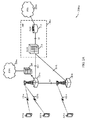
[0057]図1は、本開示の様々な態様による、ワイヤレス通信システム100の一例を示す。システム100は、基地局105と、UE115と、コアネットワーク130とを含む。コアネットワーク130は、ユーザ認証と、アクセス許可と、トラッキングと、IP接続性と、他のアクセス、ルーティング、またはモビリティ機能とを提供し得る。基地局105は、バックホールリンク132(たとえば、S1など)を通してコアネットワーク130とインターフェースする。基地局105は、UE115との通信のための無線構成およびスケジューリングを実行し得るか、または基地局コントローラ(図示せず)の制御下で動作し得る。様々な例では、基地局105は、ワイヤード通信リンクまたはワイヤレス通信リンクであり得るバックホールリンク134(たとえば、X1など)を介して互いと直接的にまたは間接的に(たとえば、コアネットワーク130を通して)通信し得る。
[0057] FIG. 1 illustrates an example of a
[0058]基地局105は、1つまたは複数の基地局アンテナを介してUE115とワイヤレスに通信することができる。基地局105の各々は、それぞれの地理的カバレージエリア110に通信カバレージを与え得る。いくつかの例では、基地局105は、基地トランシーバ局、無線基地局、アクセスポイント、無線トランシーバ、ノードB、eノードB(eNB)、ホームノードB、ホームeノードB、または何らかの他の好適な用語で呼ばれることがある。基地局105のための地理的カバレージエリア110は、カバレージエリアの一部分のみを構成するセクタに分割され得る(図示せず)。ワイヤレス通信システム100は、異なるタイプの基地局105(たとえば、マクロ基地局またはスモールセル基地局)を含み得る。異なる技術のための重複する地理的カバレージエリア110があり得る。いくつかの例では、下でより詳細に説明するように、ローカルゲートウェイ(LGW)は基地局105とコロケートされ得る。
[0058]
[0059]基地局105は、S1インターフェースによってコアネットワーク130に接続され得る。コアネットワーク130は、モビリティ管理エンティティ(MME)135と、ホーム加入者サーバ(HSS)140と、サービングゲートウェイ(SGW)145と、パケットデータネットワーク(PDN)ゲートウェイ(PGW)150とを含み得る発展型パケットコア(EPC)であり得る。ユーザIPパケットは、それ自体がPGW150に接続され得るSGW145を介して転送され得る。PGW150はIPアドレス割振りならびに他の機能を提供し得る。PGW150はネットワークオペレータのIPサービスに接続され得る。オペレータのIPサービスは、インターネットと、イントラネットと、IPマルチメディアシステム(IMS:IP Multimedia System)と、パケット交換(PS:Packet-Switched)ストリーミングサービス(PSS:PS Streaming Service)とを含み得る。MME135およびHSS140を含めて、様々なネットワークエンティティの機能について下でさらに詳細に説明する。
[0059]
[0060]マクロセルは、一般に、比較的大きい地理的エリア(たとえば、半径数キロメートル)をカバーし、ネットワークプロバイダのサービスに加入しているUE115による無制限アクセスを可能にし得る。スモールセルは、マクロセルと比較して、マクロセルと同じまたは異なる(たとえば、認可、無認可などの)周波数帯域内で動作し得る低電力基地局である。スモールセルは、様々な例によれば、ピコセル、フェムトセル、およびマイクロセルを含み得る。ピコセルは、たとえば、小さい地理的エリアをカバーし得、ネットワークプロバイダのサービスに加入しているUE115による無制限アクセスを可能にし得る。また、フェムトセルは、小さい地理的エリア(たとえば、自宅)をカバーし得、フェムトセルとの関連を有するUE115(たとえば、限定加入者グループ(CSG:closed subscriber group)中のUE115、自宅内のユーザのためのUE115など)による制限付きアクセスを与え得る。マクロセルのためのeNBはマクロeNBと呼ばれることがある。スモールセルのためのeNBは、スモールセルeNB、ピコeNB、フェムトeNB、またはホームeNBと呼ばれることがある。eNBは、1つまたは複数の(たとえば、2つ、3つ、4つなどの)セル(たとえば、コンポーネントキャリア)をサポートし得る。
[0060] The macrocell generally covers a relatively large geographic area (eg, a few kilometers in radius) and may allow unrestricted access by
[0061]ワイヤレス通信システム100は、同期動作または非同期動作をサポートすることができ得る。同期動作の場合、基地局105は同様のフレームタイミングを有し得、異なる基地局105からの送信は時間的に近似的に整合され得る。非同期動作の場合、基地局105は異なるフレームタイミングを有し得、異なる基地局105からの送信は時間的に整合されないことがある。本明細書で説明する技法は、同期動作または非同期動作のいずれにも使用され得る。
[0061]
[0062]様々な開示する例のうちのいくつかに適応し得る通信ネットワークは、階層化プロトコルスタックに従って動作するパケットベースネットワークであり得、ユーザプレーン内のデータはIPに基づき得る。無線リンク制御(RLC)レイヤが、論理チャネルを介して通信するためにパケットセグメンテーションおよびリアセンブリを実行し得る。媒体アクセス制御(MAC)レイヤが、優先度ハンドリングと、トランスポートチャネルへの論理チャネルの多重化とを実行し得る。MACレイヤはまた、リンク効率を改善するために、MACレイヤにおいて再送信を行うためにハイブリッド自動再送要求(HARQ)を使用することができる。制御プレーンでは、無線リソース制御(RRC)プロトコルレイヤは、UE115と基地局105との間のRRC接続の確立と構成と保守とを行い得る。RRCプロトコルレイヤはまた、ユーザプレーンデータのための無線ベアラのコアネットワーク130サポートのために使用され得る。物理(PHY)レイヤにおいて、トランスポートチャネルは物理チャネルにマッピングされ得る。
[0062] A communication network that may accommodate some of the various disclosed examples may be a packet-based network operating according to a layered protocol stack, and data in the user plane may be based on IP. A radio link control (RLC) layer may perform packet segmentation and reassembly to communicate over the logical channels. A medium access control (MAC) layer may perform priority handling and multiplexing of logical channels to transport channels. The MAC layer may also use hybrid automatic repeat request (HARQ) to perform retransmissions at the MAC layer to improve link efficiency. In the control plane, a radio resource control (RRC) protocol layer may establish, configure, and maintain an RRC connection between
[0063]UE115は、ワイヤレス通信システム100全体にわたって分散され得、各UE115は固定または移動であり得る。UE115は、移動局、加入者局、モバイルユニット、加入者ユニット、ワイヤレスユニット、リモートユニット、モバイルデバイス、ワイヤレスデバイス、ワイヤレス通信デバイス、リモートデバイス、モバイル加入者局、アクセス端末、モバイル端末、ワイヤレス端末、リモート端末、ハンドセット、ユーザエージェント、モバイルクライアント、クライアント、または何らかの他の好適な用語を含むか、またはそのように当業者によって呼ばれることがある。UE115は、セルラーフォン、携帯情報端末(PDA)、ワイヤレスモデム、ワイヤレス通信デバイス、ハンドヘルドデバイス、タブレットコンピュータ、ラップトップコンピュータ、コードレスフォン、ワイヤレスローカルループ(WLL)局などであり得る。UEは、マクロeNB、スモールセルeNB、リレー基地局などを含む、様々なタイプの基地局およびネットワーク機器と通信することが可能であり得る。
[0063]
[0064]ワイヤレス通信システム100に示されている通信リンク125は、UE115から基地局105へのアップリンク(UL)送信、または基地局105からUE115へのダウンリンク(DL)送信を含み得る。ダウンリンク送信は順方向リンク送信と呼ばれることもあり、アップリンク送信は逆方向リンク送信と呼ばれることもある。各通信リンク125は1つまたは複数のキャリアを含み得、各キャリアは、上記で説明した様々な無線技術に従って変調された複数のサブキャリア(たとえば、異なる周波数の波形信号)からなる信号であり得る。各被変調信号は、異なるサブキャリア上で送られ得、制御情報(たとえば、基準信号、制御チャネルなど)、オーバーヘッド情報、ユーザデータなどを搬送し得る。通信リンク125は、周波数分割複信(FDD)動作を使用して(たとえば、対スペクトルリソースを使用して)または時分割複信(TDD)動作を使用して(たとえば、不対スペクトルリソースを使用して)双方向通信を送信することができる。FDD(たとえば、フレーム構造タイプ1)およびTDD(たとえば、フレーム構造タイプ2)のためのフレーム構造が定義され得る。
[0064] The
[0065]ワイヤレス通信システム100は、複数のセルまたはキャリア上での動作、すなわち、キャリアアグリゲーション(CA)またはマルチキャリア動作と呼ばれることがある機能をサポートし得る。通信リンク125によって表されることが可能なキャリアは、コンポーネントキャリア(CC)、レイヤ、チャネルなどと呼ばれる場合もある。「キャリア」、「コンポーネントキャリア」、「セル」、および「チャネル」という用語は、本明細書では互換的に使用されることがある。UE115は、キャリアアグリゲーションのために、複数のダウンリンクCCと1つまたは複数のアップリンクCCとで構成され得る。キャリアアグリゲーションは、FDDコンポーネントキャリアとTDDコンポーネントキャリアの両方とともに使用され得る。
[0065]
[0066]場合によっては、データ(たとえば、インターネットまたはボイスオーバLTE(VoLTE)トラフィック)は、いくつかの中間エンティティを介してシステムを通してルーティングされ得る。たとえば、UE115からのデータは、通信リンク125を介して基地局105にルーティングされ、次いで、バックホールリンク132(たとえば、S1インターフェース)を介して基地局105からコアネットワーク130に、インターネットを介して別のユーザ(図示せず)にルーティングされ得る。この通信と関連付けられるレイテンシは、この通信の各終端同士の間、たとえば、UE115と他の終端におけるデータの受信者との間の様々なエンティティおよび物理的接続に応じて(be a function of)よく、30ms程度の往復時間(RTT)を有し得る。
[0066] In some cases, data (eg, Internet or Voice over LTE (VoLTE) traffic) may be routed through the system via some intermediate entities. For example, data from
[0067]しかしながら、場合によっては、データは、エンドツーエンドレイテンシを低減し得るSIPFULLを使用して、より短い経路を介してルーティングされ得る。たとえば、データは、コアネットワーク130への、およびコアネットワーク130を通した経路を回避するために、LGWを介してインターネットに直接的にルーティングされ得る。そのような場合、レイテンシは、UE115から基地局までの送信の送信時間間隔(TTI)に、HARQのRTTと関連付けられる遅延を加え、基地局105とLGWとの間の通信のための時間、およびLGWからインターネットへの通信のための時間を加えた時間に低減され得る。この手法を用いると、バックホール132と関連付けられる遅延が少なくとも回避され得、この遅延は、バックホール132の物理的属性(たとえば、ファイバまたはマイクロ波)に応じ、したがって、比較的大きい可能性がある。これは、図2A〜図2Cを参照して、下でより十分に論じられる。
[0067] However, in some cases, data may be routed over shorter paths using SIPFULL, which may reduce end-to-end latency. For example, data may be routed directly to the Internet via the LGW to avoid routes to and through
[0068]他の場合、2個のUE115は両方ともシステム100内にあり得、データは、コアネットワークをまずナビゲートする必要なしに、それらのUE同士の間でルーティングされ得る。たとえば、共通の基地局105に接続された2個のUE115は、基地局105またはLGW内でルーティングされたそれら同士の間にトラフィックを有し得る。そのような場合、レイテンシは、TTIにHARQ RTTを加えたものに、基地局105とLGWとの間の通信のための時間を加えた時間の2(2)倍に等しい値に低減され得る。この場合も、この手法を用いると、バックホール132と関連付けられる遅延が回避され得る。これもまた、図2A〜図2Cを参照して、下でより十分に論じられる。
[0068] In other cases, the two
[0069]いくつかの他の選択的IPルーティングプロトコルとは異なり、SIPFULLは、ベストエフォート型IPトラフィックオフローディングというよりもむしろ、UEのレイテンシ要件および許可(requirements and authorizations)に依存し得る。言い換えれば、システム100は、UEのレイテンシモードを決定することができ、ネットワークは、UEのレイテンシモードに基づいてルーティングを選定することができる。場合によっては、SIPFULLは、アクセスポイント名(APN)に基づいて、所与のUE115のためのシステム100内で有効化されることが可能であり、たとえば、SIPFULLは、UE115に関するレイテンシ要件を決定すると(upon)有効化され得る。
[0069] Unlike some other selective IP routing protocols, SIPFULL may rely on UE latency requirements and authorizations, rather than best-effort IP traffic offloading. In other words, the
[0070]APNは、ワイヤレスネットワークと別のコンピュータネットワーク(たとえば、インターネット)との間のゲートウェイの名称であり得る。たとえば、回路交換音声接続とは反対に、データ接続を行うUE115は、ネットワークにアクセスするとそれが伝えるAPNで構成され得る。コアネットワーク130のサーバは、次いで、何のタイプのネットワーク接続が作成されるべきか(たとえば、何のIPまたはインターネットプロトコルマルチメディアシステム(IMS)アドレスが割り当てられるべきか、または何のセキュリティ方法が使用されるべきか)を決定するために、APNを検査することができる。言い換えれば、APNは、UE115が通信することを希望するパケットデータネットワーク(PDN)を識別することができる。PDNを識別することに加えて、APNは、PDNによって提供されるサービスタイプ(たとえば、ワイヤレスアプリケーションプロトコル(WAP)サーバまたはマルチメディアメッセージングサービス(MMS))を定義するために使用されてもよい。いくつかの例では、HSS140は、UE115に関するAPN単位ベースでSIPFULLを有効化(たとえば、許可)することができる。追加または代替として、MME135は、UE115に関するAPN単位ベースでLGWを選択することができる。言い換えれば、MME135は、UE115のために構成された各ベアラに関するQoSに基づいてLGWを選択することもできる。有効化されると、UE115は、通常(たとえば、非SIPFULL動作)のために生じる請求(charges accrued)とは異なり得る、LGWの使用のために請求され得る。
[0070] An APN may be the name of a gateway between the wireless network and another computer network (eg, the Internet). For example, a
[0071]場合によっては、UE115は、ハンドオーバなど、モビリティ手順を用いて、1つの基地局105(たとえば、ソース基地局)からもう1つの基地局105(たとえば、ターゲット基地局)に転送され得る。ソース基地局105またはMME135などのネットワークエンティティは、SIPFULLが可能にされたUE115のハンドオーバを識別することができ、ネットワークエンティティは、UE115のためのサービス連続性を維持し、UE115に関するレイテンシ要件が満たされることを確実にするか、または確実にすることを試みることができる。
[0071] In some cases,
[0072]図2A〜図2Cは、本開示の様々な態様による、SIPFULLのためのワイヤレス通信システム200の例を示す。ワイヤレス通信システム200は、通信リンク125を介して通信している場合があり、図1を参照して上記で説明したUE115および基地局105の例であり得る、UE115と基地局105とを含み得る。ワイヤレス通信システム200は、1つまたは複数のLGW205と発展型パケットコア(EPC)130−aとを含み得る。EPC130−aは、図1を参照して上記で説明した例示的なコアネットワーク130であり得る。発展型パケットコア130−aは、それぞれ、図1のSGW210およびPGW140の例であり得る、SGW210とPGW215とを含み得る。LGW205およびPGW215は、PDN(たとえば、インターネット)220に対するアクセスをUE115に提供することができる。
[0072] FIGS. 2A-2C illustrate an example of a
[0073]EPC130−aは、MME135(図1)とHSS(図1)とを含み得る。MMEは、UE115とEPC130−aとの間のシグナリングを処理する制御ノードであり得る。たとえば、MMEは、ベアラおよび接続管理をUE115に提供することができる。MMEは、アイドルモードUE115に関する、トラッキングおよびページングと、ベアラのアクティブ化および非アクティブ化と、UE115のためのサービングゲートウェイ210またはローカルゲートウェイ205の選択とを担当し得る。いくつかの例では、MMEはAPN単位でローカルゲートウェイ205を選択することができる。他の例では、MMEは、各ベアラに関するQoSに基づいてLGWを選択することができる。MMEは、基地局105と通信することができ、さらにUE115を認証し、UE115との非アクセス層(NAS)シグナリングを実装することができる。HSSは、他の機能の中でも、加入者データを記憶し、ローミング制限を管理し、加入者のためのアクセス可能APNを管理し、加入者をMMEに関連付けることができる。
[0073] EPC 130-a may include an MME 135 (FIG. 1) and an HSS (FIG. 1). The MME may be a control node that handles signaling between
[0074]EPC130−aを通して送信されるユーザIPパケットは、サービングゲートウェイ210を通して転送され得る。システム200のアーキテクチャに従って、サービングゲートウェイ210は、態様ユーザプレーンであり得、eNB間ハンドオーバおよび異なる無線アクセス技術(RAT)間のハンドオーバのためのモビリティアンカーとして働き得る。PGW215は、PDN220など、1つまたは複数の外部パケットデータネットワークへの接続性を提供することができる。PDN220は、インターネット、イントラネット、IPマルチメディアシステム(IMS)、パケット交換(PS)ストリーミングサービス(PSS)、および/または他のタイプのPDNを含み得る。
[0074] User IP packets transmitted through EPC 130-a may be forwarded through serving
[0075]SIPFULLが有効化されるとき、UE115とPDN220−bとの間のユーザプレーントラフィックがEPC130−aから導出され、ローカルゲートウェイ205基地局105−aとPDN220−aとの間のSGi接続にオフロードされ得る。ローカルゲートウェイ205とPDN220−aとの間のSGi接続を介したベアラトラフィックをサポートするために、ローカルゲートウェイ205は、S5インターフェースを介してサービングゲートウェイ210と通信することができる。SIPFULLは、ネットワークポリシーのセットおよび/またはUE115についての加入情報に基づいて、SIPFULLがUE115の接続に対して許可されるとMMEが決定した場合、接続性アクティブ化中にUE115のPDN接続のために有効化され得る。接続に対してSIPFULLが許可されると決定すると、MMEは、ローカルゲートウェイ205のネットワークアドレスを使用して接続ためのSIPFULLベアラをセットアップしてよい。MMEは、基地局105−aとの通信(たとえば、S1制御メッセージによる)、1つまたは複数のオペレーションアドミニストレーションおよびマネジメント(OAM)メッセージ、または他の通信ソースに基づいて、ローカルゲートウェイ205のネットワークアドレスを決定することができる。
[0075] When SIPFULL is enabled, user plane traffic between the
[0076]図2Aに示すように、基地局105−aなど、いくつかの基地局105は、コロケートLGW205と構成され得る。基地局105−aは、X2共通制御メッセージを使用して、ネイバー基地局105−bと通信することができる。したがって、基地局105−aは、X2インターフェースのセットアップ中に、そのローカルゲートウェイ205のネットワークアドレスをネイバー基地局105−bに提供することができる。結果として、ネイバー基地局105−bに接続されたUE115−cは、ローカルゲートウェイ205を介してデータトラフィックをPDN220−aにリダイレクトすることによって、SIPFULLを利用するように適合され得る。基地局105−a、LGW205、またはEPC130−a内のエンティティなど、ネットワークエンティティは、UE115(たとえば、UE115−a)のレイテンシモードを決定することができる。図2Bに示すように、基地局105−aおよび105−bなど、いくつかの基地局105は、コロケートLGW205と構成され得る。図2Cに示すような、他の例では、LGW205は、SGW210と関連付けられるか、またはコロケートされてよく、独立型LGWと呼ばれる場合がある。
[0076] As shown in FIG. 2A, some
[0077]しかしながら、図3を参照して下で説明するように、LGW205のロケーションにかかわらず、SIPFULLが有効化され、APN単位ベースでLGW205が選択され得る。たとえば、ネットワークエンティティは、レイテンシモードに基づいて、UE115−aのAPNに関して低レイテンシIPパケットルーティング(たとえば、SIPFULL)を有効化することができ、ネットワークエンティティは、APNに基づいて、低レイテンシIPパケットルーティングのためのLGWを選択することができる。場合によっては、ネットワークエンティティは、UE115のために構成された各ベアラに関するQoSを決定し、決定されたQoSに基づいてLGWを選択することができる。
[0077] Regardless of the location of the
[0078]追加または代替として、トラフィックは共通の基地局105内でルーティングされ得る。たとえば、UE115−aと115−bとの間のトラフィックは基地局105−a内でルーティングされ得る。たとえば、UE115−aは、共通の基地局105−aによってサービスされるピアUE115−bとの通信を確立するように要求することができる。たとえば、基地局105−a、LGW205、またはEPC130−a内のエンティティなどのネットワークエンティティは、UE115−aおよび115−bが共通の基地局105−aに接続されていると決定することができる。ネットワークエンティティは、UE115−aおよび115−bが同じレイテンシモードを有する(たとえば、両方ともSIPFULLが可能にされている)と決定することもでき、それは、したがって、基地局105−aを用いてUE115−aと115−bとの間でパケットデータトラフィックをルーティングすることができる。
[0078] Additionally or alternatively, traffic may be routed within
[0079]いくつかの例では、UE115−aは、それがUE115−bと共通の基地局に接続していると決定することができる。UE115−aは、したがって、基地局内通信要求を基地局105−aに、または基地局105−aを介してEPC130−aに送信することができる。UE115−aは、次いで、UE115−bと通信することができ、これは、基地局内通信のための許可の受信時であり得る。 [0079] In some examples, UE 115-a may determine that it is connected to a common base station with UE 115-b. UE 115-a may thus send an intra-base station communication request to base station 105-a or to EPC 130-a via base station 105-a. UE 115-a may then communicate with UE 115-b, which may be upon receiving a grant for intra-base station communication.
[0080]他の例では、UE115同士の間のトラフィックは、EPC130−aを通過せずに、基地局105同士の間でルーティングされ得る。たとえば、UE115−aと115−cとの間のトラフィックは、基地局105−aと105−bとの間のX2インターフェースを介してルーティングされ得る。上記で説明したように、ネットワークエンティティは、UE115−aおよび115−cが、それぞれ、基地局105−aおよび105−bに接続されていると決定することができる。ネットワークエンティティは、UE115−aおよび115−cが同じレイテンシモードを有すると決定することもでき、したがって、それは、基地局105−aと105−bとの間のX2インターフェースを介してUE115−aと115−cとの間でパケットデータトラフィックをルーティングすることができるか、またはトラフィックはLGW205−aと205−bとの間でルーティングされ得る。
[0080] In another example, traffic between
[0081]またさらなる例では、UE115同士の間のトラフィックは、PGW215を通過せずにSGW210を介してルーティングされ得る。したがって、たとえば、UE115−bと115−cとの間のトラフィックは、基地局105−aおよび105−b、ならびにS1インターフェースを介してSGW210を介してルーティングされ得る。したがって、ネットワークエンティティは、上記で説明したように、UE115−bおよび115−cが共通のSGWに接続されていると決定することができる。ネットワークエンティティは、UE115−bおよび115−cが同じレイテンシモードを有すると決定することもでき、したがって、それは、SGW210を介してUE115−aと115−cとの間でパケットデータトラフィックをルーティングすることができ、またはトラフィックは、LGW205−aと205−bとの間でルーティングされ得る。UE115同士の間のルーティングは、パケットデータコンバージェンスプロトコル(PDCP)レイヤ、または下位レイヤにおいて実行され得る。場合によっては、ネットワークエンティティは、UE115−aと115−cとの間でルーティングされたパケットをSGWから受信することができる。
[0081] In yet a further example, traffic between
[0082]いくつかの例では、コンテンツ配信のためのレイテンシを低減するのを助けるために、たとえば、EPC130−aのエッジ付近のコンテンツキャッシングが採用され得る。たとえば、LGW205、SGW210、またはPGW215は、キャッシュされたコンテンツのためのローカルサーバを含み得る。他の例では、独立型コンテンツサーバ(図示せず)がEPC130−b内に含まれてよい。普及している、または頻繁にアクセスされるコンテンツはこれらのサーバにおいて記憶され得る。たとえば、ネットワークオペレータは、いくつかのUE115からの要求に基づいて、これらのサーバにおいてキャッシュを構築することができる。したがって、いくつかの例では、ユーザが、UE115を介して、コンテンツ(たとえば、ビデオ)に関するドメインネームシステム(DNS)ルックアップを実行するとき、DNSはネットワークエンティティのローカルサーバにおけるキャッシュにUE115を導くことができる。これは、バックホール送信および処理遅延を回避することによってレイテンシを削減するのにさらに役立つ可能性があり、上記で論じたSIPFULL手順とともに採用され得る。
[0082] In some examples, for example, content caching near the edge of EPC 130-a may be employed to help reduce latency for content distribution. For example,
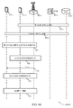
[0083]システム200内で実装され可能である様々なSIPFULL手順について、図3〜図4Bを参照して説明する。図3は、本開示の様々な態様による、超低レイテンシをサポートするためのコールフロー300の一例を示す。コールフロー300は、図1〜図2を参照して上記で説明したUE115の一例であり得るUE115−dを含み得る。通信図300はまた、図1〜図2を参照して上記で説明した基地局105の一例であり得る基地局105−cを含み得る。図3は、各々、図1〜図2Cを参照して説明したLGW205、MME135、またはHSS140の例であり得る、LGW205−dと、MME305とHSS310とをさらに含み得る。LGW205−dは、図2A〜図2Cを参照して説明したように、様々に位置し得る。
[0083] Various SIPFULL procedures that may be implemented within the
[0084]UE115−dは、MME305との初期アタッチ要求312を行うことができる。初期アタッチ要求312は、オプションで、UE115−dに関してSIPFULLが許可され得るAPNを識別することができる。いくつかの例では、UE115−dは、初期アタッチ要求312内にSIPFULL要求を指示することができる。追加または代替として、UE115−dは、初期アタッチ要求312内のSIPFULL要求と関連付けられるQoS要件を識別することができる。MME305は、UE115−dから要求を受信し、UE115−dに関する加入情報に基づいて、UE115−dが要求されたAPNとのPDN接続のためにSIPFULLを使用することが許可されるかどうかを検証することができる。場合によっては、MME305は、UE115−dから受信されたQoS要件と関連付けられるSIPFULLに関するフロー単位ベースの許可(per flow based authorization)を実行することができる。MME305は、要求されるAPNとのPDN接続が許可されるかどうかを検証するために、UE115−dに関する加入情報をたとえば、HSS310から受信することができる。
[0084] UE 115-d may make an initial attach
[0085]MME305は、HSS310から取得された加入情報に基づいて、APNまたは他のAPNと関連付けられるトラフィックが許可され得るか、または禁止され得るかを指示することができる。UE115−dが関連するAPNに関してSIPFULLを利用することが許可されるとMME305が決定する場合、MME305は、SIPFULLコロケートLGW205−dがUE115−dに関して確立されるべきであることを基地局105−cに指示することができる314。追加または代替として、MME305は、SIPFULL PDN接続確立のために独立型LGW205−dを選択することができる。それに応じて、基地局105−cは、RRC接続再構成メッセージ316をUE115−dに送信することができる。RRC接続再構成メッセージ316は、UE115−dとの無線ベアラを確立することによって、SIPFULLを利用して、新しいPDN接続のためにUE115−dを構成することができる。その後、基地局105−cは、UE115−dのためのLGW205−dに対する直接ユーザプレーン経路318を有効化し得る。UE115−dは、データリンク322および324を介して、基地局105−cおよびLGW205−dを介してデータを送受信することができる。いくつかの例では、SIPFULLサービスは、ユーザに対する高まったコストと関連付けられることが可能であり、したがって、ローカルゲートウェイ205−dは、SIPFULLサービスを利用してオフロードされたデータ量に基づいて、請求記録(charging record)326を作成することができる。
[0085] Based on the subscription information obtained from the
[0086]図4Aおよび図4Bは、本開示の様々な態様による、超低レイテンシをサポートするためのコールフロー400の一例を示す。図4Aの例は、図1〜図3を参照して上記で説明した、UE115および基地局105の例であり得る、UE115−eおよび115−fと、基地局105−dとを含み得る。コールフロー400−aは、各々、図1〜図2Cを参照して説明した、MME135もしくは305、またはHSS140もしくは310の例であり得る、MME305−aとHSS310−aとを含むこともできる。
[0086] FIGS. 4A and 4B illustrate an example of a
[0087]第1のUE(たとえば、UE115−f)は、SIPFULLに対する許可を取得するか、SIPFULLを有効化するために、レイテンシモードを含み得る登録メッセージ402をMME305−aに送信することができる。いくつかの例では、登録要求はAPNと関連付けられ得る。HSS310−aから取得された加入者情報に基づいて、MME305−aは、SIPFULLに対するUE115−f要求を許可するか、または拒否することのいずれかが可能である。MME305−aが登録要求を許可する場合、MME305−aはその許可について基地局105−dに通知することができる。
[0087] The first UE (eg, UE 115-f) may send a
[0088]第2のUE(たとえば、115−e)は、SIPFULL機能を取得するために登録要求をMME305−aに送信することもできる404。第2のUE115−eから発行された登録要求の許可に基づいて、MME305−aは、第1および第2のUE115と関連付けられる情報を記憶することができる406。いくつかの例では、記憶されたUE情報は、第1および第2のUE識別(UEID)と、第1および第2のUE IPアドレスと、関連する基地局105−dとを含み得る。
[0088] The second UE (eg, 115-e) may also send 404 a registration request to MME 305-a to obtain a SIP FULLL function. Based on the permission of the registration request issued from the second UE 115-e, the MME 305-a can store 406 information associated with the first and
[0089]第1のUE(たとえば、UE115−f)は、第2のUE(たとえば、UE115−e)を対象とする通信を指示して、基地局105−dとのRRC接続を確立することができる408。基地局105−dは、RRC接続要求408を受信し、対象とするターゲットとしてUE115−eを識別するとすぐ、サービス要求412をMME305−aに転送することができる。それに応じて、MME305−aは、対象とするUE115−eが第1のUE115−fと共通の基地局105−dを共有することを検出することができる414。いくつかの例では、MME305−aは、各UE115と関連付けられる加入者データに基づいて、第1のUE115−fと第2のUE115−eの両方がSIPFULL機能で許可されるとさらに決定することができる。この決定に基づいて、MME305−aは、基地局内ルーティングを確立するために、検出された情報を基地局105−dに転送する(forward)ことができる。
[0089] The first UE (eg, UE 115-f) directs communication intended for a second UE (eg, UE 115-e) to establish an RRC connection with base station 105-d. 408 that can be. Upon receiving the
[0090]したがって、基地局105−dは、基地局105−dとの第2のRRC接続416を確立するように、第2のUE115−eにページングすることができる415。第1のUE115−fおよび第2のUE115−eは、次いで、データをコアネットワークにルーティングせずに、基地局105−dを介してeNB間通信を実行することができる418。
[0090] Accordingly, base station 105-
[0091]図4Bの例は、図1〜図3を参照して上記で説明した、UE115および基地局105の例であり得る、UE115−eおよび115−fと、基地局105−dとを含み得る。コールフロー400−bは、各々、図1〜図2Cを参照して説明した、MME135もしくは305、またはHSS140もしくは310であり得る、MME305−aとHSS310−aとを含むこともできる。
[0091] The example of FIG. 4B includes UEs 115-e and 115-f and base station 105-d, which may be examples of
[0092]UE115は、各々、図4Aを参照して上記で説明したように、ステップ402−aおよび404−aにおいて、MME305−aにそのSIPFULL能力を登録する。いくつかの例では、第1のUE115−fは、第2のUE115−fが共通の基地局105−d上に位置することを発見することができる422。この発見は、第1または第2のUE115のいずれかが基地局105−dによってサービスされる近くのUE115を発見するためのメッセージを基地局105−dに送信することに基づき得る。他の例では、第1のUE115−fは、第2のUE115−eが基地局105−d上の第1のUE115−dを発見することを可能にするために、基地局105−dを介してその存在をブロードキャストまたは告知することができる。結果として、第1のUE115−fは、第2のUE115−eとの通信を確立するための第1のUEの115−f意図を識別して、基地局105−dとRRC接続424を確立することができる。それに応じて、基地局105−dは、第2のUE115−eにページングし425、基地局105−dとRRC接続426を確立するように第2のUE115−eに催促する。確立されたRRC接続に基づいて、第1および第2のUE115は、コアネットワークを通してデータパケットをルーティングせずに、基地局105−dを介してeNB間通信428を確立することができる。
[0092] The
[0093]図5A〜図5Dは、本開示の様々な態様による、超低レイテンシをサポートするためのハンドオーバに関するコールフロー500の例を示す。SIPTO(選択されたIPトラフィックオフローディング)をサポートするためのハンドオーバにも同様の手順が適用され得る。図5A〜図5Dの例は、図1〜図2Cを参照して上記で説明したUE115、基地局105、LGW205、およびPDN220の例であり得る、UE115−gと、基地局105と、LGW205と、PDN220−cとを含み得る。
[0093] FIGS. 5A-5D illustrate an example of a
[0094]図5Aの例では、UE115−gは、基地局105−fに対するハンドオーバが完了するまで、基地局105−eまたはLGW205−eによって割り当てられたIPアドレスを維持することができる。UE115−gは測定報告502をソース基地局105−eに送ることができる。測定報告502は、ソース基地局105−eとUE115−gとの間の信号強度またはチャネル品質に関係し得るモビリティシナリオを識別することができる。測定報告502に基づいて、ソース基地局105−eは、ハンドオーバ要求504をターゲット基地局105−fに送ることができる。いくつかの例では、ハンドオーバ要求504を送ることは、ソース基地局105−eからターゲット基地105−fへの低レイテンシIPルーティング指示を備える。他の例では、ハンドオーバ要求504は、UE115−gに対するSIPFULL許可をターゲット基地局105−fに指示するためのSIPFULL識別子を含み得る。追加または代替として、ソース基地局105−eは、低レイテンシIPパケットルーティングをサポートするためのターゲット基地局の能力に少なくとも部分的に基づいて、ターゲット基地局を選択することができる。
[0094] In the example of FIG. 5A, UE 115-g may maintain the IP address assigned by base station 105-e or LGW 205-e until the handover to base station 105-f is completed. UE 115-g may send a
[0095]ハンドオーバ要求504を受信することに基づいて、ターゲット基地局105−fは、ハンドオーバ要求肯定応答(ACK)506をソース基地局105−eに送信することができる。ハンドオーバACK506は、ソース基地局105−eにおけるターゲット基地局105−fからの低レイテンシIPルーティング指示を備え得る。いくつかの例では、ソース基地局105−eは、ステータス転送メッセージ508をターゲット基地局105−fに送信することができる。ソース基地局105−eは、ソース基地局105−eからターゲット基地局105−fへのハンドオフをトリガするために、ハンドオフコマンド512をUE115−gに発行することもできる。拡張アクセス手順514は、このようにして、UE115−gとターゲット基地局105−fとの間で実装され得る。拡張アクセス手順の一環として、UE115−gは、RRC再確立手順516を開始し、ハンドオーバ完了メッセージ518をターゲット基地局105−fに送信することができる。
[0095] Based on receiving the
[0096]ハンドオーバ中に、宛先IPアドレスと、イングレスアドレスフィルタリングを迂回する(bypass)必要性とに基づいて、UE115−gからのアップリンクデータ522はターゲット基地局105−fを介してPDN220−cに直接的にルーティングされ得る524。しかしながら、このプロセス中、UE115−gは、ソースローカルゲートウェイ205−eによって前にそれに割り当てられたIPアドレスを維持することができる。いくつかの例では、アップリンクデータ522は、PDN220−cにルーティングされる524のに先立って、ターゲット基地局105−fからソース基地局105−eに送信され得る。逆に、前に割り当てられたIPアドレスを用いてUE115−gにアドレス指定されたPDN220−cからのダウンリンクデータ526は、まずソース基地局105−eを通過することによって、UE115−gにルーティングされ得る。ダウンリンクデータ526は、次いで、ターゲット基地局105−fからUE115−gに送信されるのに先立って、ターゲット基地局105−fに再度ルーティングされ得る528。
[0096] During handover, based on the destination IP address and the need to bypass ingress address filtering,
[0097]データ通信が完了すると534、ターゲット基地局105−fまたはLGW205−fは、新しいまたは更新されたIPアドレスをUE115−bに割り振ることができる。ターゲット基地局105−fは、いくつかの例では、UE115−gと関連付けられる非アクティビティタイマーを監視することによって、データ通信の完了を検出することができる。したがって、ターゲット基地局105−fは、データ完了についてLGW205−fに指示し、LGW205−fからUE115−gに関する新しいIPアドレスを要求することができる。追加または代替として、データ完了は、非アクティビティ時間を監視することによって、ソース基地局105−eによって検出され得る。いくつかの例では、ソース基地局は、データ完了についてターゲット基地局105−fに指示することができる。他の例では、保留中の(pending)データ通信セッションが完了すると、UE115−g自体が、ターゲットローカルゲートウェイ205−fから新しいIPアドレス割振り536を要求することができる。いくつかの例では、ソース基地局105−eは、その後、UEコンテキストリリース538を受信することができ、UE115−gはアイドル状態542に戻ることができる。いくつかの例では、UE115−gがソース基地局105−eおよびターゲット基地局105−fのカバレージエリア同士の間を往復するとき、迅速な(rapid)IPアドレス割当てを防ぐために、ヒステリシスタイマーが利用され得る。
[0097] Upon completion of the
[0098]図5Bの例では、UE115−gは、データ通信セッションが完了するまで、ソースローカルゲートウェイ205−eによって割り当てられたIPアドレスを使用し続けることができる。メッセージ502−aから518−aにおける通信は、図5Aを参照して説明したステップ502から518と同様であり得る。しかしながら、UE115−gは、ハンドオーバ完了メッセージ518−aをターゲット基地局105−fに転送すると、ターゲットLGW205−fとPDN接続を確立することができる544。結果として、ターゲットLGW205−fと関連付けられる新しいIPアドレスがUE115−gに割り当てられ得る。新しいIPアドレスの割当てにかかわらず、データ通信セッションの完了まで546、UE115−gはソースローカルゲートウェイ205−eと関連付けられる前のIPアドレスを利用し続けることができる。
[0098] In the example of FIG. 5B, UE 115-g may continue to use the IP address assigned by source local gateway 205-e until the data communication session is completed. Communication in messages 502-a through 518-a may be similar to
[0099]UE115−gは、新しいIPアドレスに切り替えるようにUE115−gに要求するメッセージ548をMME505から受信することができる。追加または代替として、UE115−gは、そのバッファされたデータが前のIPアドレスを通して完全に送信されると、新しいIPアドレスに切り替えるようにMME505に要求することができる。したがって、UE115−gは、ターゲットローカルゲートウェイ205−fと関連付けられる新しいIPアドレスを利用して、ターゲット基地局105−fと通信することができる552。追加または代替として、MME505は、UEコンテストリリースコマンド554をソース基地局105−eにさらに送信することができる。
[0099] UE 115-g may receive a
[0100]図5Cの例では、UE115−gは、ハンドオーバ手順を開始する前に、ターゲットLGW205−fから新しいIPアドレスが割り当てられてよい。結果として、ハンドオーバプロセスが完了すると、UE115−gは新しいIPアドレスに速やかに切り替えることができる。UE115−gは、測定報告502−bをソース基地局105−eに送信することができる。測定報告502は、ソース基地局105−eとUE115−gとの間の信号強度またはチャネル品質に関係し得るモビリティシナリオを識別することができる。いくつかの例では、測定報告502の受信はハンドオーバをトリガし得る。測定報告502に基づいて、ソース基地局105−eは、ハンドオーバ要求504−bをターゲット基地局105−fに送信することができる。
[0100] In the example of FIG. 5C, UE 115-g may be assigned a new IP address from target LGW 205-f before initiating the handover procedure. As a result, upon completion of the handover process, UE 115-g can quickly switch to a new IP address. UE 115-g may transmit measurement report 502-b to source base station 105-e.
[0101]ターゲット基地局105−fは、UE115−gに関する新しいIPアドレスをターゲットローカルゲートウェイ205−fから受信することができる。したがって、ターゲット基地局105−fは、新しいIPアドレス556を割り振り、ハンドオーバ要求ACKメッセージ558をソース基地局105−eに送信することができる。ハンドオーバ要求ACKメッセージは、たとえば、UE115−gに関する新しく割り振られたIPアドレスを含み得る。それに応じて、ソース基地局105−eは、新しく割り振られたIPアドレスをさらに備え得るハンドオーバコマンド562をUE115−gに送信することができる。一例では、ソース基地局105−eは、ステータス転送メッセージ564をターゲット基地局105−fに送信することができる。
[0101] The target base station 105-f may receive a new IP address for the UE 115-g from the target local gateway 205-f. Accordingly, the target base station 105-f can allocate a
[0102]新しいIPアドレスの割振りに続いて、UE115−gは、拡張アクセス手順566を開始し、RRC再確立手順568を開始することができる。いくつかの例では、UE115−gは、ハンドオーバ(または、ハンドオフ)完了コマンド572をターゲット基地局105−fに送信し、その後、ターゲットLGW205−fから受信された、新しく割り当てられたIPアドレスを利用して、ターゲット基地局105−fとのデータ通信574を確立することができる。上記で論じたように、いくつかの例では、ターゲット基地局105−fは、UEコンテキストリリースコマンド576をソース基地局105−eに発行することができる。
[0102] Following allocation of the new IP address, UE 115-g may initiate an
[0103]次に、図5Dの例では、UE115−gは、ソース基地局105−eとの接続が失われる前に、ハンドオーバを完了することができる。UE115−gは、測定報告502−cをソース基地局105−eに送信することができる。UE115−gは、次いで、ソース基地局105−eとUE115−gとの間の信号強度が事前構成されたしきい値を下回ると決定することができる578。いくつかの例では、ネットワークは、RRCシグナリングを通してしきい値限界を識別し、UE115−gに送ることができる。検出された信号品質に基づいて、UE115−gは、ターゲット基地局105−fとの拡張アクセス手順582を開始することができる。拡張アクセス手順582は、UE115−gのSIPFULL能力を含み得る。本開示によれば、ターゲット基地局105−fは、UE115−gのSIPFULL能力を検証するために、MME505に連絡する(contact)ことができる584。
[0103] Next, in the example of FIG. 5D, UE 115-g may complete the handover before the connection with source base station 105-e is lost. UE 115-g may transmit a measurement report 502-c to source base station 105-e. UE 115-g may then determine 578 that the signal strength between source base station 105-e and UE 115-g is below a preconfigured threshold. In some examples, the network may identify the threshold limit through RRC signaling and send it to UE 115-g. Based on the detected signal quality, UE 115-g may initiate an
[0104]本開示のいくつかの例では、ターゲット基地局105−fは、MME505から許可を受信すると、ターゲットLGW205−fからUE115−gに関する新しいIPアドレスを要求することができる。ターゲット基地局105−fは、割り振られたIPアドレス586をUE115−gに送信することができる。ターゲット基地局105−fは、UEコンテキストリリースコマンド588をソース基地局105−eに送信することもできる。ソース基地局105−eは、受信されたUEコンテキストリリース588に少なくとも部分的に基づいて、ハンドオーバ要求592をターゲット基地局に送信することができる592。いくつかの例では、ターゲット基地局105−fは、ハンドオーバ要求ACKメッセージ594を用いてハンドオーバ要求592に応答することができる。連続的に、ターゲット基地局105−fは、そこからUE115−gがRRC再確立手順516−cを開始することができるRRC接続再確立メッセージ596をUE115−gに発行することもできる。1つまたは複数の例では、ソース基地局105−eは、ステータス転送メッセージ598をターゲット基地局105−fに送信することができる。
[0104] In some examples of the present disclosure, upon receiving a grant from
[0105]UE115−gは、このようにして、ターゲット基地局105−fによって割り振られたIPアドレスを利用して、ターゲット基地局105−fとのデータ通信522−bを確立することができる。いくつかの例では、UE115−gとのデータ通信の確立時に、ターゲット基地局105−fは、UEコンテキストリリース554−bメッセージをソース基地局105−eに送信することができる。UE115−gのIPアドレスが変更されるとき、ソケット(たとえば、TCPソケット)は、場合によっては、速やかに閉鎖し、これにより、パイプライン内にデータの損失を引き起こす可能性がある。データの損失を低減するために、本開示は、ハンドオーバ中に両方のIPアドレス(すなわち、前のIPアドレスおよび新しいIPアドレス)がアクティブな状態に留まることを可能にし得る。いくつかの例では、バッファされたデータが前のIPアドレスを通して送信されるとき、UE115−gは新しいIPアドレスに切り替えることができる。代替として、保留中のデータ送信が完了するまで、UE115−gは前のIPアドレスを利用することができる。そのような場合、ネットワークは、UE115−gがアイドル状態に入るのに先立って、新しいIPアドレスを割り当てることができる。結果として、前のIPアドレスと関連付けられるソケットは閉鎖され得、新しいIPアドレスと関連付けられる新しいソケットが開放され得る。 [0105] The UE 115-g can thus establish data communication 522-b with the target base station 105-f using the IP address allocated by the target base station 105-f. In some examples, upon establishing data communication with UE 115-g, target base station 105-f may send a UE context release 554-b message to source base station 105-e. When the IP address of the UE 115-g is changed, the socket (eg, TCP socket) may close quickly in some cases, which may cause data loss in the pipeline. To reduce data loss, the present disclosure may allow both IP addresses (ie, the old IP address and the new IP address) to remain active during the handover. In some examples, UE 115-g may switch to a new IP address when the buffered data is sent through the previous IP address. Alternatively, UE 115-g may utilize the previous IP address until the pending data transmission is completed. In such a case, the network may assign a new IP address before the UE 115-g enters the idle state. As a result, the socket associated with the previous IP address may be closed and a new socket associated with the new IP address may be opened.
[0106]図6は、本開示の様々な態様による、選択されたIPフロー超低レイテンシのために構成されたUE115−hのブロック図600を示す。UE115−hは、図1〜図5を参照して説明したUE115の態様の一例であり得る。UE115−hは、受信機605と、通信管理モジュール610と、送信機615とを含み得る。UE115−hはプロセッサをも含み得る。これらの構成要素の各々は互いと通信し得る。
[0106] FIG. 6 illustrates a block diagram 600 of a UE 115-h configured for selected IP flow ultra-low latency, in accordance with various aspects of the present disclosure. The UE 115-h may be an example of the aspect of the
[0107]受信機605は、パケット、ユーザデータ、または様々な情報チャネルに関連する制御情報(たとえば、制御チャネル、データチャネル、および選択されたIPフロー超低レイテンシに関係する情報など)などの情報を受信することができる。情報は、通信管理モジュール610に、およびUE115−hの他の構成要素に受け渡されてよい。いくつかの例では、受信機605は、ソースLGWによって割り振られたIPアドレスを利用して、ターゲット基地局からダウンリンクデータを受信することができ、ここで、ダウンリンクデータはソース基地局を介してルーティングされる。受信機605は、ソースLGWによって割り振られたIPアドレスを利用して、ターゲット基地局からダウンリンクデータを受信することもでき、ここで、ダウンリンクデータはソース基地局を介してルーティングされる。いくつかの例では、受信機605はソース基地局においてデータを受信することができる。
[0107]
[0108]通信管理モジュール610は、レイテンシモード信号をネットワークに送信し、レイテンシモード信号に少なくとも部分的に基づいて、低レイテンシIPパケットルーティングのための許可信号を受信し、許可信号に少なくとも部分的に基づいて、ローカルゲートウェイ(LGW)を介して許可信号に従ってパケットをルーティングすることができる。場合によっては、低レイテンシIPパケットルーティングは、レイテンシモード信号、もしくは加入者情報、または両方に基づいて、APNに関して許可される。いくつかの例では、レイテンシモード信号は、SIPFULLの許可または有効化の要求である。追加または代替として、レイテンシモード信号は、UE115−hが低レイテンシモードで動作することが可能であるという指示であり得る。
[0108] The
[0109]送信機615は、UE115−hの他の構成要素から受信された複数の信号を送信することができる。いくつかの例では、送信機615は、トランシーバモジュール内で受信機605とコロケートされ得る。送信機615は、単一のアンテナを含んでよく、またはそれは複数の(several)アンテナを含んでもよい。いくつかの例では、送信機615は、ソースLGWによって割り振られたIPアドレスを利用して、アップリンクデータをターゲット基地局に送信することができる。いくつかの例では、送信機615は、ソースLGWによって割り振られたIPアドレスを利用して、アップリンクデータをターゲット基地局に送信することができる。他の例では、送信機615は、新しいIPアドレス割振りされたフォームザターゲットLGWを利用して(utilizing the new IP address allocated form the target LGW)、ターゲット基地局と通信することができる。
[0109] The
[0110]図7は、本開示の様々な態様による、選択されたIPフロー超低レイテンシのためのUE115−iのブロック図700を示す。UE115−iは、図1〜図6を参照して説明したUE115の態様の一例であり得る。UE115−iは、受信機605−a、通信管理モジュール610−a、または送信機615−aを含み得る。UE115−iはプロセッサをも含み得る。これらの構成要素の各々は互いと通信し得る。通信管理モジュール610−aは、レイテンシモード送信モジュール705と、許可受信モジュール710と、通信モジュール715とを含むことも可能である。
[0110] FIG. 7 illustrates a block diagram 700 of a UE 115-i for selected IP flow ultra-low latency, in accordance with various aspects of the present disclosure. The UE 115-i may be an example of the aspect of the
[0111]受信機605−aは、通信管理モジュール610−aに、およびUE115−iの他の構成要素に受け渡され得る情報を受信することができる。通信管理モジュール610−aは、図6を参照して上記で説明した動作を実行することができる。送信機615−aは、UE115−iの他の構成要素から受信された信号を送信し得る。 [0111] The receiver 605-a may receive information that may be passed to the communication management module 610-a and to other components of the UE 115-i. The communication management module 610-a can execute the operation described above with reference to FIG. Transmitter 615-a may transmit signals received from other components of UE 115-i.
[0112]レイテンシモード送信モジュール705は、図2〜図5を参照して上記で説明したように、レイテンシモード信号をネットワークに送信することができる。レイテンシモード信号は、たとえば、SIPFULLの許可または有効化のための要求であり得る。許可受信モジュール710は、図2〜図5を参照して上記で説明したように、レイテンシモード信号、加入者情報、または両方に少なくとも部分的に基づいて、APNに関して低レイテンシIPパケットルーティングのための許可信号を受信することができる。通信モジュール715は、図2〜図5を参照して上記で説明したように、許可信号に少なくとも部分的に基づいて、LGWを介して許可信号に従ってパケットをルーティングすることができる。
[0112] Latency
[0113]図8は、本開示の様々な態様による、選択されたIPフロー超低レイテンシのための通信管理モジュール610−bのブロック図800を示す。通信管理モジュール610−bは、図6〜図7を参照して説明した通信管理モジュール610の態様の一例であり得る。通信管理モジュール610−bは、レイテンシモード送信モジュール705−aと、許可受信モジュール710−aと、通信モジュール715−aとを含み得る。これらのモジュールの各々は、図7を参照して上記で説明した機能を実行することができる。通信管理モジュール610−bは、QoS識別モジュール805と、基地局間識別モジュール810と、通信確立モジュール815と、ルーティングモジュール820と、測定報告モジュール825と、連続性確立モジュール830と、IPアドレス割振りモジュール835と、IPアドレス指向性モジュール(IP address directive module)840と、通信再確立モジュール845とを含むことも可能である。
[0113] FIG. 8 shows a block diagram 800 of a communication management module 610-b for selected IP flow ultra-low latency, in accordance with various aspects of the present disclosure. The communication management module 610-b may be an example of the mode of the
[0114]QoS識別モジュール805は、QoS指示をネットワークに送信することができ、ここにおいて、許可信号は、図2〜図5を参照して上記で説明したように、QoS指示に少なくとも部分的に基づく。基地局間識別モジュール810は、図2〜図5を参照して上記で説明したように、UEが共通の基地局に接続されていると決定することができる。通信確立モジュール815は、図2〜図5を参照して上記で説明したように、基地局内通信要求をネットワークに送信することができる。
[0114] The
[0115]ルーティングモジュール820は、共通の基地局を介してUEと通信することができ、UEとのパケットデータトラフィックは、図2〜図5を参照して上記で説明したように、共通の基地局内でルーティングされる。ルーティングモジュール820は、ターゲットLGWから割り振られた新しいIPアドレスを利用して、ターゲット基地局と通信することもできる。
[0115] The
[0116]測定報告モジュール825は、図2〜図5を参照して上記で説明したように、測定報告をソース基地局に送信することができる。連続性確立モジュール830は、図2〜図5を参照して上記で説明したように、測定報告に少なくとも部分的に基づいて開始されたハンドオーバ中にサービス連続性を維持することができる。
[0116] The
[0117]IPアドレス割振りモジュール835は、図2〜図5を参照して上記で説明したように、ターゲット基地局と関連付けられるターゲットLGWから新しいIPアドレス割振りを受信することができる。IPアドレス割振りモジュール835は、ターゲット基地局と関連付けられるターゲットLGWから新しいIPアドレス割振りを受信することもできる。IPアドレス割振りモジュール835は、ターゲット基地局と関連付けられるターゲットLGWから割り振られた新しいIPアドレスを受信することもできる。IPアドレス割振りモジュール835は、ターゲット基地局と関連付けられるターゲットLGWから割り振られた新しいIPアドレスをMMEから受信することもできる。
[0117] The IP
[0118]IPアドレス指向性モジュール840は、図2〜図5を参照して上記で説明したように、新しいIPアドレスを利用するための指示をMMEから受信することができる。通信再確立モジュール845は、図2〜図5を参照して上記で説明したように、ターゲット基地局とのRRC接続を再確立することができる。通信再確立モジュール845は、ターゲット基地局との無線リソース制御(RRC)接続を再確立することもできる。
[0118] The IP
[0119]UE115−h、UE115−i、または通信管理モジュール610−bの構成要素は、適用可能な機能の一部(some)または全部をハードウェアで実行するように適合された少なくとも1つの特定用途向け集積回路(ASIC)を用いて、個々にまたはまとめて(collectively)実装され得る。代替として、それらの機能は、少なくとも1つの集積回路(IC)上で、1つまたは複数の他の処理ユニット(またはコア)によって実行され得る。他の実施形態では、当技術分野で知られている任意の様式でプログラムされ得る他のタイプの集積回路(たとえば、ストラクチャード/プラットフォームASIC、フィールドプログラマブルゲートアレイ(FPGA)、または別のセミカスタムIC)が使用され得る。各ユニットの機能はまた、全体的または部分的に、1つまたは複数の汎用プロセッサまたは特定用途向けプロセッサによって実行されるようにフォーマットされた、メモリ中に組み込まれた命令を用いて実装され得る。 [0119] The components of the UE 115-h, UE 115-i, or the communication management module 610-b may include at least one identification adapted to perform some or all of the applicable functions in hardware. It can be implemented individually or collectively using an application specific integrated circuit (ASIC). Alternatively, those functions may be performed by at least one other processing unit (or core) on at least one integrated circuit (IC). In other embodiments, other types of integrated circuits (eg, structured / platform ASICs, field programmable gate arrays (FPGAs), or another semi-custom IC) that can be programmed in any manner known in the art. Can be used. The functionality of each unit may also be implemented, in whole or in part, with instructions embodied in memory, formatted to be executed by one or more general-purpose or special-purpose processors.
[0120]図9は、本開示の様々な態様による、選択されたIPフロー超低レイテンシのために構成されたUE115を含むシステム900を示す。システム900は、図1〜図8を参照して上記で説明したUE115の一例であり得るUE115−jを含み得る。UE115−jは、図6〜図8を参照して説明した通信管理モジュール610の一例であり得る通信管理モジュール910を含み得る。UE115−jはサービス維持モジュール925をも含み得る。UE115−jは、通信を送信するための構成要素と通信を受信するための構成要素とを含む、双方向音声およびデータ通信のための構成要素をも含み得る。たとえば、UE115−jは、UE115−kまたは基地局105−gと双方向に通信し得る。
[0120] FIG. 9 illustrates a
[0121]いくつかの例では、サービス維持モジュール925は、図2〜図5を参照して上記で説明したように、新しいIPアドレスを利用するための指示をMMEから受信することができる。追加または代替として、サービス維持モジュール925は、ハンドオーバ期間中にUE115−jがソースローカルゲートウェイと関連付けられる前に割り当てられたIPアドレスからターゲットローカルゲートウェイと関連付けられる新しく割り当てられたIPアドレスにいつ切り替えるべきかを決定することができる。1つまたは複数の例では、サービス維持モジュール925は、ハンドオーバ手順中に、低レイテンシIPパケットルーティングに関係するサービス連続性を維持するのに役立ち(assist)得る。
[0121] In some examples, the
[0122]UE115−jは、プロセッサモジュール905と、(ソフトウェア(SW)920を含む)メモリ915と、トランシーバモジュール935と、1つまたは複数のアンテナ940とを含むことも可能であり、その各々は、(たとえば、バス945を介して)直接または間接的に、互いと通信し得る。トランシーバモジュール935は、上記で説明したように、アンテナ940またはワイヤードリンクもしくはワイヤレスリンクを介して、1つまたは複数のネットワークと双方向に通信し得る。たとえば、トランシーバモジュール935は、基地局105または別のUE115と双方向に通信し得る。トランシーバモジュール935は、パケットを変調し、変調されたパケットを送信のためにアンテナ940に提供し、アンテナ940から受信されたパケットを復調するためのモデムを含み得る。UE115−jは単一のアンテナ940を含み得るが、UE115−jはまた、複数のワイヤレス送信を同時に送信または受信することが可能な複数のアンテナ940を有し得る。
[0122] UE 115-j may also include a
[0123]メモリ915は、ランダムアクセスメモリ(RAM)と読取り専用メモリ(ROM)とを含み得る。メモリ915は、実行されると、プロセッサモジュール905に本明細書で説明する様々な機能(たとえば、選択されたIPフロー超低レイテンシなど)を実行させる命令を含むコンピュータ可読、コンピュータ実行可能ソフトウェア/ファームウェアコード920を記憶することができる。代替として、ソフトウェア/ファームウェアコード920は、プロセッサモジュール905によって直接的に実行可能でないことがあるが、(たとえば、コンパイルされ、実行されたとき)コンピュータに本明細書で説明する機能を実行させることができる。プロセッサモジュール905は、インテリジェントハードウェアデバイス(たとえば、中央処理ユニット(CPU)、マイクロコントローラ、ASICなど)を含み得る。
[0123] The
[0124]図10は、本開示の様々な態様による、選択されたIPフロー超低レイテンシのために構成されたネットワークエンティティのブロック図1000を示す。ネットワークエンティティは、概して、基地局105−hの観点から説明され得るが、図10を参照して説明する機能は、上記で説明したように、LGW、SGW、MMEなどによって実装され(implemented)得ることを諒解されたい。したがって、基地局105−h、またはネットワークエンティティは、図1〜図9を参照して説明した、基地局105、LGW205、SGW145もしくは210、またはMME135もしくは305の態様の一例であり得る。基地局105−hは、受信機1005と、ネットワーク通信管理モジュール1010と、送信機1015とを含み得る。基地局105−hはプロセッサをも含み得る。これらの構成要素の各々は互いと通信し得る。
[0124] FIG. 10 illustrates a block diagram 1000 of a network entity configured for selected IP flow ultra-low latency, in accordance with various aspects of the present disclosure. Although network entities may be generally described in terms of base station 105-h, the functions described with reference to FIG. 10 may be implemented by an LGW, SGW, MME, etc., as described above. Please understand that. Accordingly, the base station 105-h, or network entity, may be an example of aspects of the
[0125]受信機1005は、パケット、ユーザデータ、または様々な情報チャネルに関連する制御情報(たとえば、制御チャネル、データチャネル、および選択されたIPフロー超低レイテンシに関係する情報など)などの情報を受信することができる。情報は、ネットワーク通信管理モジュール1010に、および基地局105−hの他の構成要素に受け渡されてよい。いくつかの例では、受信機1005は、ソース基地局の一態様であってよく、ソースLGWによって割り振られたIPアドレスを利用して、ターゲット基地局からダウンリンクデータを受信することができ、ここにおいて、ダウンリンクデータはソース基地局を介してルーティングされる。いくつかの例では、受信機1005は、ソースLGWによって割り振られたIPアドレスを利用して、ターゲット基地局からダウンリンクデータを受信することができ、ここにおいて、ダウンリンクデータはソース基地局を介してルーティングされる。いくつかの例では、受信機1005はソース基地局においてデータを受信することができる。
[0125] The
[0126]ネットワーク通信管理モジュール1010は、第1のUEのレイテンシモードを決定し、第1のUEのレイテンシモードに少なくとも部分的に基づいて、第1のUEの低レイテンシIPパケットルーティング(low latency IP packet routing the first UE)を有効化し、第1のUEの低レイテンシモードに少なくとも部分的に基づいて、低レイテンシIPパケットルーティングのためのLGWを選択することができる。いくつかの例では、低レイテンシIPパケットルーティングは、第1のUEのレイテンシモードと関連付けられるAPNに関して有効化され得る。さらに、LGWはAPNに基づいて選択され得る。
[0126] The network
[0127]送信機1015は、基地局105−hの他の構成要素から受信された信号を送信することができる。いくつかの実施形態では、送信機1015は、トランシーバモジュール内で受信機1005とコロケートされ得る。送信機1015は、単一のアンテナを含むことが可能であり、またはそれは、いくつかのアンテナを含み得る。いくつかの例では、送信機1015は、ソース基地局の一態様であり得、それは、ソースLGWによって割り振られたIPアドレスを利用して、アップリンクデータをターゲット基地局に送信することができる。いくつかの例では、送信機1015は、ハンドオーバ手順の一環として、ソースLGWによって割り振られたIPアドレスを利用して、アップリンクデータをターゲット基地局に送信することができる。いくつかの例では、送信機1015は、新しいIPアドレス割振りされたフォームザターゲットLGWを利用して、ターゲット基地局と通信することができる。
[0127] The
[0128]図11は、本開示の様々な態様による、選択されたIPフロー超低レイテンシのためのネットワークエンティティのブロック図1100を示す。ネットワークエンティティは、概して、図1〜図10を参照して説明した基地局105の態様の一例であり得る基地局105−iの観点から説明される場合がある。代替として、参照する(reference)基地局105−iを用いて説明する機能は、前の図において説明した、LGW205、SGW145もしくは210、またはMME135もしくは305など、基地局以外のネットワークエンティティにおいて実装され得る。基地局105−iは、受信機1005−a、ネットワーク通信管理モジュール1010−a、または送信機1015−aを含み得る。ネットワーク通信モジュール1010−aは、低レイテンシ管理モジュール1102と、ハンドオーバ管理モジュール1104とを含み得る。基地局105−iはプロセッサをも含み得る。これらの構成要素の各々は互いと通信し得る。低レイテンシ管理モジュール1102は、モード識別モジュール1105と、低レイテンシ認証モジュール1110と、ローカルゲートウェイ選択モジュール1115とを含み得る。
[0128] FIG. 11 shows a block diagram 1100 of a network entity for selected IP flow ultra-low latency, in accordance with various aspects of the present disclosure. The network entities may be described generally in terms of a base station 105-i, which may be an example of an aspect of the
[0129]受信機1005−aは、ネットワーク通信管理モジュール1010−aに、および基地局105−iの他の構成要素に受け渡され得る情報を受信することができる。ネットワーク通信管理モジュール1010−aは、図10を参照して上記で説明した動作を実行することができる。低レイテンシモジュール1102およびその様々なサブモジュールは、SIPFULL動作を管理することができる。ハンドオーバ管理モジュール1104は、たとえば、SIPFULL許可UEのハンドオーバ動作を管理または実装することができる。送信機1015−aは、基地局105−iの他の構成要素から受信された信号を送信することができる。
[0129] The receiver 1005-a can receive information that can be passed to the network communication management module 1010-a and to other components of the base station 105-i. The network communication management module 1010-a can execute the operation described above with reference to FIG. The
[0130]モード識別モジュール1105は、図2〜図5を参照して上記で説明したように、第1のUEのレイテンシモードを決定することができる。たとえば、モード識別モジュール1105は、UEがSIPFULL可能であるか、またはSIPFULLに関して許可されているかを決定することができる。低レイテンシ許可モジュール1110は、図2〜図5を参照して上記で説明したように、第1のUEのレイテンシモードに少なくとも部分的に基づいて、第1のUEに関して低レイテンシIPパケットルーティングを有効化することができる。場合によっては、低レイテンシIPパケットルーティングは、第1のUEのレイテンシモードと関連付けられるAPNに関して有効化され得る。
[0130] The
[0131]ローカルゲートウェイ選択モジュール1115は、図2〜図5を参照して上記で説明したように、第1のUEの低レイテンシモードに基づいて、低レイテンシIPパケットルーティングのためのローカルゲートウェイ(LGW)を選択することができる。場合によっては、LGWはAPNに基づいて選択され得る。ローカルゲートウェイ選択モジュール1115は、決定されたQoSに基づいてLGWを選択することもできる。いくつかの例では、ローカルゲートウェイ選択モジュール1115によって選択されたLGWは第1の基地局とコロケートされた第1のLGWを含む。ローカルゲートウェイ選択モジュール1115は、第2の基地局とコロケートされた第2のLGWを選択することもできる。
[0131] The local
[0132]図12Aは、本開示の様々な態様による、選択されたIPフロー超低レイテンシのための低レイテンシ管理モジュール1102−aのブロック図1200−aを示す。低レイテンシ管理モジュール1102−aは、図11を参照して説明した低レイテンシ管理モジュール1102の態様の一例であり得る。いくつかの例では、低レイテンシ管理モジュール1102−aは、前の図(preceding figures)において説明したように、基地局105の構成要素である。他の例では、低レイテンシ管理モジュール1102−aは、前の図において説明したMME135または305など、MMEの構成要素である。さらに他の例では、低レイテンシ管理モジュール1102−aは、前の図において説明したLGW205またはSGW145もしくは210の態様の一例であり得る。
[0132] FIG. 12A shows a block diagram 1200-a of a low latency management module 1102-a for selected IP flow ultra-low latency, in accordance with various aspects of the present disclosure. The low latency management module 1102-a may be an example of a mode of the low
[0133]低レイテンシ管理モジュール1102−aは、モード識別モジュール1105−aと、低レイテンシ認証モジュール1110−aと、ローカルゲートウェイ選択モジュール1115−aとを含み得る。これらのモジュールの各々は、図11を参照して上記で説明した機能を実行することができる。低レイテンシ管理モジュール1102−aは、QoS決定モジュール1205と、通信管理モジュール1210と、共有eNB接続性モジュール1215と、レイテンシモード識別モジュール1220と、パケットルーティングモジュール1225と、ネイバーeNB接続性モジュール1230と、共有ゲートウェイ識別モジュール1235とを含むことも可能である。
[0133] The low latency management module 1102-a may include a mode identification module 1105-a, a low latency authentication module 1110-a, and a local gateway selection module 1115-a. Each of these modules can perform the functions described above with reference to FIG. The low latency management module 1102-a includes a
[0134]QoS決定モジュール1205は、図2〜図5を参照して上記で説明したように、第1のUEのために構成された各ベアラに関するQoSを決定することができる。通信管理モジュール1210は、図2〜図5を参照して上記で説明したように、LGWが基地局とコロケートされ得るように構成され得る。いくつかの例では、LGWは、コアネットワーク内でSGWとコロケートされ得る。共有eNB接続性モジュール1215は、図2〜図5を参照して上記で説明したように、第1のUEおよび第2のUEが共通の基地局に接続されていると決定することができる。
[0134] The
[0135]レイテンシモード識別モジュール1220は、図2〜図5を参照して上記で説明したように、第2のUEのレイテンシモードが第1のUEのレイテンシモードと同じであると決定することができる。レイテンシモード識別モジュール1220は、第2のUEのレイテンシモードが第1のUEのレイテンシモードと同じであると決定することができる。
[0135] The latency
[0136]パケットルーティングモジュール1225は、図2〜図5を参照して上記で説明したように、第2のUEのレイテンシモードが第1のUEのレイテンシモードと同じであると決定することに少なくとも部分的に基づいて、共通の基地局内で第1のUEと第2のUEとの間でパケットデータトラフィックをルーティングすることができる。いくつかの例では、パケットデータトラフィックはIPパケットデータを含み、ルーティングはLGWを介し得る。パケットデータトラフィックはパケットデータを含んでよく、ルーティングは、パケットデータコンバージェンスプロトコル(PDCP)レイヤまたは下位レイヤにあり得る。いくつかの例では、LGWは、共通の基地局とコロケートされ得る。
[0136] The
[0137]追加または代替として、パケットルーティングモジュール1225は、第1の基地局と第2の基地局との間のダイレクトバックホールリンクを介して第1のUEと第2のUEとの間でパケットデータトラフィックをルーティングすることができる。いくつかの例では、パケットデータトラフィックはIPパケットデータを含み、ルーティングはLGWを介し得る。いくつかの例では、パケットルーティングモジュール1225は、第1および第2のLGWを介してパケットデータトラフィックをルーティングすることができる。LGWは、たとえば、コアネットワーク内のサービングゲートウェイ(SGW)とコロケートされてよく、ルーティングはLGWを介し得る。パケットルーティングモジュール1225は、他の例では、SGW内で第1のUEと第2のUEとの間でパケットデータトラフィックをルーティングすることができる。またさらなる例では、パケットルーティングモジュール1225は、図2〜図5を参照して上記で説明したように、LGWまたはSGWにおいてデータをキャッシュすることができる。パケットルーティングモジュール1225は、いくつかの例では、SGWから第1のUEと第2のUEとの間でルーティングされたパケットを受信することができる。
[0137] Additionally or alternatively, the
[0138]ネイバーeNB接続性モジュール1230は、第1のUEが第1の基地局に接続され、第2のUEが第2の基地局に接続されていると決定することができ、ここにおいて、第1および第2の基地局は、図2〜図5を参照して上記で説明したように、ダイレクトバックホールリンクを介して通信している。いくつかの例では、共有ゲートウェイ識別モジュール1235は、図2〜図5を参照して上記で説明したように、第1および第2のUEが共通のSGWに接続されていると決定することができる。
[0138] The neighbor
[0139]図12Bは、本開示の様々な態様による、選択されたIPフロー超低レイテンシのためのハンドオーバ管理モジュール1104−aのブロック図1200−bを示す。ハンドオーバ管理モジュール1104−aは、図11を参照して説明したハンドオーバ管理モジュール1104の態様の一例であり得る。いくつかの例では、ハンドオーバ管理モジュール1104−aは、前の図において説明したように、基地局105の構成要素である。他の例では、ハンドオーバ管理モジュール1104−aは、前の図において説明したMME135または305など、MMEの構成要素である。さらに他の例では、ハンドオーバ管理モジュール1104−aは、LGW205またはSGW145もしくは210の態様の一例であり得る。
[0139] FIG. 12B shows a block diagram 1200-b of the handover management module 1104-a for selected IP flow ultra-low latency, in accordance with various aspects of the present disclosure. The handover management module 1104-a may be an example of the mode of the
[0140]ハンドオーバ管理モジュール1104−aは、ハンドオーバ識別モジュール1240、サービス連続性モジュール1245、ハンドオーバ要求送信モジュール1250、ハンドオーバ肯定応答モジュール1255、ターゲット基地局選択モジュール1260、データ送信モジュール1265、送信完了モジュール1270、コンテキストリリースモジュール1275、IPアドレス割当てモジュール1280、コンテキスト要求モジュール1285を含み得る。
[0140] The handover management module 1104-a includes a
[0141]ハンドオーバ識別モジュール1240は、図2〜図5を参照して上記で説明したように、ソース基地局からターゲット基地局への第1のUEのハンドオーバを識別することができる。サービス連続性モジュール1245は、図2〜図5を参照して上記で説明したように、ハンドオーバ中に低レイテンシIPパケットルーティングに関するサービス連続性を維持するのに役立ち得る。ハンドオーバ要求送信モジュール1250は、図2〜図5を参照して上記で説明したように、ソース基地局からターゲット基地局への、低レイテンシIPルーティング指示を含むハンドオーバ要求を送ること、または識別することができる。ハンドオーバ要求送信モジュール1250は、ソース基地局からターゲット基地局への、低レイテンシIPルーティング指示を含み得る、ハンドオーバ要求を送ること、または識別することもできる。いくつかの例では、ハンドオーバ要求送信モジュール1250は、コンテキスト要求に応じて、ソース基地局からターゲット基地局へのハンドオーバ要求を送ること、または識別することができる。
[0141] The
[0142]ハンドオーバ肯定応答モジュール1255は、図2〜図5を参照して上記で説明したように、ソース基地局においてターゲット基地局から低レイテンシIPルーティング指示を含み得るハンドオーバ肯定応答を受信すること、または認識することができる。ハンドオーバ肯定応答モジュール1255は、ソース基地局において、ターゲット基地局からの低レイテンシIPルーティング指示とIPアドレスとを含み得るハンドオーバ肯定応答を受信すること、または認識することもできる。ハンドオーバ肯定応答モジュール1255は、いくつかの例では、ハンドオーバ要求に応じて、ターゲット基地局からソース基地局においてハンドオーバ肯定応答を受信すること、または認識することができる。
[0142] The
[0143]ターゲット基地局選択モジュール1260は、図2〜図5を参照して上記で説明したように、低レイテンシIPパケットルーティングをサポートするためのターゲット基地局の能力に基づいて、ソース基地局についての、またはソース基地局に対するターゲット基地局を選択することができる。データ送信モジュール1265は、図2〜図5を参照して上記で説明したように、LGWによって割り振られたIPアドレスを使用して、ターゲット基地局を介してデータを第1のUEに送信することができる。
[0143] The target base
[0144]送信完了モジュール1270は、図2〜図5を参照して上記で説明したように、第1のUEへのデータ転送が完了したことを決定することができる。いくつかの例では、送信完了モジュールは、図2〜図5を参照して上記で説明したように、たとえば、ハンドオーバ肯定応答に応じて、ステータス転送メッセージを送ることができる。コンテキストリリースモジュール1275は、図2〜図5を参照して上記で説明したように、ターゲット基地局からのUEコンテキストリリースを受信すること、または認識することができる。コンテキストリリースモジュール1275は、ステータス転送メッセージに続いて、および成功裏の(successful)ハンドオーバ時に、ターゲット基地局からソース基地局においてコンテキストリリースを受信すること、または認識することもできる。
[0144] The
[0145]IPアドレス割当てモジュール1280は、図2〜図5を参照して上記で説明したように、ソース基地局からUEにIPアドレスを送信することができる。コンテキスト要求モジュール1285は、図2〜図5を参照して上記で説明したように、ターゲット基地局からソース基地局においてコンテキスト要求を受信することができる。
[0145] The IP
[0146]基地局105−h、基地局105−i、低レイテンシ管理モジュール1102−a、またはハンドオーバ管理モジュール1104−aの構成要素は、適用可能な機能の一部または全部をハードウェアで実行するように適合された少なくとも1つのASICを用いて、個々にまたはまとめて実装され得る。代替として、それらの機能は、1つまたは複数の他の処理ユニット(またはコア)によって、少なくとも1つのIC上で実行され得る。他の実施形態では、当技術分野で知られている任意の様式でプログラムされ得る他のタイプの集積回路(たとえば、ストラクチャード/プラットフォームASIC、FPGA、または別のセミカスタムIC)が使用され得る。各ユニットの機能はまた、全体的または部分的に、1つまたは複数の汎用プロセッサまたは特定用途向けプロセッサによって実行されるようにフォーマットされた、メモリ中に組み込まれた命令を用いて実装され得る。 [0146] The components of the base station 105-h, the base station 105-i, the low latency management module 1102-a, or the handover management module 1104-a perform some or all of the applicable functions in hardware. May be implemented individually or collectively using at least one ASIC adapted as such. Alternatively, those functions may be performed on at least one IC by one or more other processing units (or cores). In other embodiments, other types of integrated circuits (eg, structured / platform ASICs, FPGAs, or another semi-custom IC) may be used that can be programmed in any manner known in the art. The functionality of each unit may also be implemented, in whole or in part, with instructions embodied in memory, formatted to be executed by one or more general-purpose or special-purpose processors.
[0147]図13は、本開示の様々な態様による、選択されたIPフロー超低レイテンシのために構成された基地局105を含むシステム1300を示す。システム1300は、図1〜図12を参照して上記で説明した基地局105の一例であり得る基地局105−jを含み得る。基地局105−jは、図10〜図12Bを参照して説明したネットワーク通信管理モジュール1010の一例であり得るネットワーク通信管理モジュール1310を含み得る。基地局105−jは、通信を送信するための構成要素と通信を受信するための構成要素とを含む、双方向音声およびデータ通信のための構成要素をも含み得る。たとえば、基地局105−jは、UE115−lまたはUE115−mと双方向に通信し得る。
[0147] FIG. 13 shows a
[0148]場合によっては、基地局105−jは、1つまたは複数のワイヤードバックホールリンクを有し得る。基地局105−jは、前の図を参照して説明した、コアネットワークまたはEPC130の一例であり得るコアネットワーク130−dに対するワイヤードバックホールリンク(たとえば、S1インターフェースなど)を有し得る。基地局105−jは、基地局間バックホールリンク(たとえば、X2インターフェース)を介して、基地局105−kおよび基地局105−lなど、他の基地局105と通信することもできる。基地局105の各々は、同じまたは異なるワイヤレス通信技術を使用してUE115と通信することができる。場合によっては、基地局105−jは、基地局通信モジュール1325を利用して105−kまたは105−lなど、他の基地局と通信することもできる。いくつかの実施形態では、基地局通信モジュール1325は、基地局105のうちのいくつかの間の通信を行うために、LTE/LTE−Aワイヤレス通信ネットワーク技術内のX2インターフェースを提供することができる。いくつかの実施形態では、基地局105−jは、コアネットワーク130を通して他の基地局と通信することができる。場合によっては、基地局105−jは、ネットワーク通信モジュール1330を通してコアネットワーク130と通信することができる。
[0148] In some cases, base station 105-j may have one or more wired backhaul links. Base station 105-j may have a wired backhaul link (eg, an S1 interface, etc.) to core network 130-d, which may be an example of a core network or
[0149]基地局105−jは、プロセッサモジュール1305と、(ソフトウェア(SW)1320を含む)メモリ1315と、トランシーバモジュール1335と、アンテナ1340とを含み得、その各々は、(たとえば、バスシステム1345を介して)直接または間接的に互いと通信していることがある。トランシーバモジュール1335は、アンテナ1340を介して、マルチモードデバイスであり得るUE115と双方向に通信するように構成され得る。トランシーバモジュール1335(または、基地局105−kの他の構成要素)はまた、アンテナ1340を介して、1つまたは複数の他の基地局(図示せず)と双方向に通信するように構成され得る。トランシーバモジュール1335は、パケットを変調し、変調されたパケットを送信のためにアンテナ1340に提供し、アンテナ1340から受信されたパケットを復調するように構成されたモデムを含み得る。基地局105−jは、各々が1つまたは複数の関連付けられるアンテナ1340をもつ複数のトランシーバモジュール1335を含み得る。トランシーバモジュールは、図10の組み合わせられた受信機1005および送信機1015の一例であり得る。
[0149] The base station 105-j may include a
[0150]メモリ1315は、RAMとROMとを含み得る。メモリ1315はまた、実行されるとプロセッサモジュール1305に本明細書で説明する様々な機能(たとえば、選択されたIPフロー超低レイテンシ、メッセージルーティングなど)を実行させるように構成された命令を含んでいるコンピュータ可読、コンピュータ実行可能ソフトウェアコード1320を記憶することができる。代替として、ソフトウェア1320は、プロセッサモジュール1305によって直接的に実行可能でないことがあるが、たとえば、コンパイルされ実行されると、コンピュータに本明細書で説明する機能を実行させるように構成され得る。プロセッサモジュール1305は、インテリジェントハードウェアデバイス、たとえば、CPU、マイクロコントローラ、ASICなどを含み得る。プロセッサモジュール1305は、エンコーダ、キュー処理モジュール、ベースバンドプロセッサ、無線ヘッドコントローラ、デジタル信号プロセッサ(DSP)など、様々な専用プロセッサを含み得る。
[0150] The
[0151]基地局通信モジュール1325は、他の基地局105との通信を管理し得る。通信管理モジュールは、他の基地局105と協働してUE115との通信を制御するためのコントローラまたはスケジューラを含み得る。たとえば、基地局通信モジュール1325は、ビームフォーミングまたはジョイント送信などの様々な干渉緩和技法のためのUE115への送信のためのスケジューリングを協調させ得る。
[0151] Base
[0152]図14は、本開示の様々な態様による、選択されたIPフロー超低レイテンシのための方法1400を示すフローチャートを示す。方法1400の動作は、図1〜図13を参照して説明したように、基地局、MME、LGW、SGWなど、または、その構成要素、を含むネットワークエンティティによって実装され得る。たとえば、方法1400の動作は、図10〜図13を参照して説明したようにネットワーク通信管理モジュール1010によって実行され得る。いくつかの例では、ネットワークエンティティは、以下で説明する機能を実行するためにネットワークエンティティの機能要素を制御するためのコードのセットを実行することができる。追加または代替として、ネットワークエンティティは、専用ハードウェアを使用して、以下で説明する態様機能を実行することができる。
[0152] FIG. 14 shows a flowchart illustrating a
[0153]ブロック1405において、ネットワークエンティティは、図2〜図5を参照して上記で説明したように、第1のUEのレイテンシモードを決定することができる。いくつかの例では、ブロック1405の動作は、図11を参照して上記で説明したように、モード識別モジュール1105によって実行され得る。
[0153] At
[0154]ブロック1410において、ネットワークエンティティは、図2〜図5を参照して上記で説明したように、第1のUEのレイテンシモードに少なくとも部分的に基づいて、第1のUEのための低レイテンシIPパケットルーティングを有効化することができる。場合によっては、低レイテンシIPパケットルーティングは、第1のUEのレイテンシモードと関連付けられるAPNに関して有効化され得る。いくつかの例では、ブロック1410の動作は、図11を参照して上記で説明したように、低レイテンシ認証モジュール1110によって実行され得る。
[0154] At
[0155]ブロック1415において、ネットワークエンティティは、図2〜図5を参照して上記で説明したように、第1のUEの低レイテンシモードに少なくとも部分的に基づいて、低レイテンシIPパケットルーティングのためのローカルゲートウェイ(LGW)を選択することができる。場合によっては、LGWはAPNに基づいて選択され得る。いくつかの例では、ブロック1415の動作は、図11を参照して上記で説明したように、ローカルゲートウェイ選択モジュール1115によって実行され得る。
[0155] At
[0156]図15は、本開示の様々な態様による、選択されたIPフロー超低レイテンシのための方法1500を示すフローチャートを示す。方法1800の動作は、図1〜図13を参照して説明したように、基地局、MME、LGW、SGWなどを含むネットワークエンティティによって実装され得る。たとえば、方法1500の動作は、図10〜図13を参照して説明したようにネットワーク通信管理モジュール1010によって実行され得る。いくつかの例では、ネットワークエンティティは、以下で説明する機能を実行するためにネットワークエンティティの機能要素を制御するためのコードのセットを実行することができる。追加または代替として、ネットワークエンティティは、専用ハードウェアを使用して、以下で説明する態様機能を実行することができる。方法1500はまた、図14の方法1400の態様を組み込み得る。
[0156] FIG. 15 shows a flowchart illustrating a
[0157]ブロック1505において、ネットワークエンティティは、図2〜図5を参照して上記で説明したように、第1のUEのレイテンシモードを決定することができる。いくつかの例では、ブロック1505の動作は、図11を参照して上記で説明したように、モード識別モジュール1105によって実行され得る。
[0157] At
[0158]ブロック1510において、ネットワークエンティティは、図2〜図5を参照して上記で説明したように、第1のUEのレイテンシモードに少なくとも部分的に基づいて、第1のAPのための低レイテンシIPパケットルーティングを有効化することができる。場合によっては、低レイテンシIPパケットルーティングは、第1のUEのレイテンシモードと関連付けられるAPNに関して有効化され得る。いくつかの例では、ブロック1510の動作は、図11を参照して上記で説明したように、低レイテンシ認証モジュール1110によって実行され得る。
[0158] At
[0159]ブロック1515において、ネットワークエンティティは、図2〜図5を参照して上記で説明したように、第1のUEのために構成された各ベアラに関するQoSを決定することができる。いくつかの例では、ブロック1515の動作は、図12を参照して上記で説明したように、QoS決定モジュール1205によって実行され得る。
[0159] At
[0160]ブロック1520において、ネットワークエンティティは、図2〜図5を参照して上記で説明したように、第1のUEの低レイテンシモードと、決定されたQoSとに少なくとも部分的に基づいて、低レイテンシIPパケットルーティングのためのローカルゲートウェイ(LGW)を選択することができる。場合によっては、LGWはAPNに基づいて同様に選択され得る。いくつかの例では、ブロック1520の動作は、図11を参照して上記で説明したように、ローカルゲートウェイ選択モジュール1115によって実行され得る。いくつかの例では、ネットワークエンティティは、LGWにおいてデータをキャッシュすることもできる。
[0160] At
[0161]図16は、本開示の様々な態様による、選択されたIPフロー超低レイテンシのための方法1600を示すフローチャートを示す。方法1600の動作は、図1〜図13を参照して説明したように、基地局、MME、LGW、SGWなどを含むネットワークエンティティによって実装され得る。たとえば、方法1600の動作は、図10〜図13を参照して説明したようにネットワーク通信管理モジュール1010によって実行され得る。いくつかの例では、ネットワークエンティティは、以下で説明する機能を実行するためにネットワークエンティティの機能要素を制御するためのコードのセットを実行することができる。追加または代替として、ネットワークエンティティは、専用ハードウェアを使用して、以下で説明する態様機能を実行することができる。方法1600はまた、図14または図15の方法1400および方法1500の態様を組み込み得る。
[0161] FIG. 16 shows a flowchart illustrating a
[0162]ブロック1605において、ネットワークエンティティは、図2〜図5を参照して上記で説明したように、第1のUEのレイテンシモードを決定することができる。いくつかの例では、ブロック1605の動作は、図11を参照して上記で説明したように、モード識別モジュール1105によって実行され得る。
[0162] At
[0163]ブロック1610において、ネットワークエンティティは、図2〜図5を参照して上記で説明したように、第1のUEのレイテンシモードに少なくとも部分的に基づいて、第1のUEのための低レイテンシIPパケットルーティングを有効化することができる。場合によっては、低レイテンシIPパケットルーティングは、第1のUEのレイテンシモードと関連付けられるAPNに関して有効化され得る。いくつかの例では、ブロック1610の動作は、図11を参照して上記で説明したように、低レイテンシ認証モジュール1110によって実行され得る。
[0163] At
[0164]ブロック1615において、ネットワークエンティティは、図2〜図5を参照して上記で説明したように、第1のUEの低レイテンシモードに少なくとも部分的に基づいて、低レイテンシIPパケットルーティングのためのローカルゲートウェイ(LGW)を選択することができる。場合によっては、LGWはAPNに基づいて同様に選択され得る。いくつかの例では、ブロック1615の動作は、図11を参照して上記で説明したように、ローカルゲートウェイ選択モジュール1115によって実行され得る。
[0164] At
[0165]ブロック1620において、ネットワークエンティティは、図2〜図5を参照して上記で説明したように、第1のUEおよび第2のUEが共通の基地局に接続されていると決定することができる。いくつかの例では、ブロック1620の動作は、図12を参照して上記で説明したように、共有eNB接続性モジュール1215によって実行され得る。
[0165] At
[0166]ブロック1625において、ネットワークエンティティは、図2〜図5を参照して上記で説明したように、第2のUEのレイテンシモードが第1のUEのレイテンシモードと同じであると決定することができる。いくつかの例では、ブロック1625の動作は、図12を参照して上記で説明したように、レイテンシモード識別モジュール1220によって実行され得る。
[0166] At
[0167]ブロック1630において、ネットワークエンティティは、図2〜図5を参照して上記で説明したように、第2のUEのレイテンシモードが第1のUEのレイテンシモードと同じであると決定することに少なくとも部分的に基づいて、共通の基地局内で第1のUEと第2のUEとの間でパケットデータトラフィックをルーティングすることができる。いくつかの例では、ブロック1630の動作は、図12を参照して上記で説明したように、パケットルーティングモジュール1225によって実行され得る。
[0167] At
[0168]この方法は、第1のUEのために構成された各ベアラに関するサービス品質(QoS)を決定することと、決定されたQoSに少なくとも部分的に基づいてLGWを選択することとを含むこともできる。いくつかの例では、この方法は、第1のUEおよび第2のUEが共通の基地局に接続されていると決定することと、第2のUEのレイテンシモードが第1のUEのレイテンシモードと同じであると決定することと、第2のUEのレイテンシモードが第1のUEのレイテンシモードと同じであると決定することに基づいて、共通の基地局内で第1のUEと第2のUEとの間でパケットデータトラフィックをルーティングすることとをさらに含み得る。他の例では、この方法は、第1のUEが第1の基地局に接続され、第2のUEが第2の基地局に接続されていると決定することと、ここで、第1および第2の基地局がダイレクトバックホールリンクを介して通信している、第2のUEのレイテンシモードが第1のUEのレイテンシモードと同じであると決定することと、第1の基地局と第2の基地局との間のダイレクトバックホールリンクを介して第1のUEと第2のUEとの間でパケットデータトラフィックをルーティングすることとを含み得る。場合によっては、ルーティングは、LGWを介し、LGWは第1の基地局とコロケートされた第1のLGWを備え、この方法は、第2の基地局とコロケートされた第2のLGWを選択することと、第1のLGWおよび第2のLGWを介してパケットデータトラフィックをルーティングすることとを含み得る。 [0168] The method includes determining a quality of service (QoS) for each bearer configured for the first UE, and selecting an LGW based at least in part on the determined QoS. You can also. In some examples, the method includes determining that the first UE and the second UE are connected to a common base station, and determining that a latency mode of the second UE is a latency mode of the first UE. And the first UE and the second UE in a common base station based on determining that the latency mode of the second UE is the same as the latency mode of the first UE. Routing packet data traffic to and from the UE. In another example, the method includes determining that the first UE is connected to the first base station and the second UE is connected to the second base station, wherein the first and second UEs are connected to the first base station. Determining that the latency mode of the second UE is the same as the latency mode of the first UE, wherein the second base station is communicating over the direct backhaul link; Routing packet data traffic between the first UE and the second UE via a direct backhaul link between the two base stations. In some cases, the routing is via the LGW, the LGW comprises a first LGW co-located with the first base station, and the method comprises selecting a second LGW co-located with the second base station. And routing packet data traffic through the first LGW and the second LGW.
[0169]この方法はまた、第1のUEおよび第2のUEが共通のサービスゲートウェイ(SGW)に接続されていると決定することと、第2のUEのレイテンシモードが第1のUEのレイテンシモードと同じであると決定することと、第1のUEと第2のUEとの間でルーティングされたパケットをSGWから受信することとを含み得る。場合によっては、この方法は、ソース基地局からターゲット基地局への第1のUEのハンドオーバを識別することと、ハンドオーバ中に低レイテンシIPパケットルーティングに関するサービス連続性を維持することと、低レイテンシIPルーティング指示を備えるハンドオーバ要求をソース基地局からターゲット基地局に送ることと、ソース基地局においてターゲット基地局から低レイテンシIPルーティング指示を備えるハンドオーバ肯定応答を受信することとを含み得る。さらなる例では、この方法は、低レイテンシIPパケットルーティングをサポートするためのターゲット基地局の能力に少なくとも部分的に基づいて、ソース基地局によってターゲット基地局を選択することと、低レイテンシIPルーティング指示を備えるハンドオーバ要求をソース基地局からターゲット基地局に送ることと、ソース基地局においてターゲット基地局から低レイテンシIPルーティング指示とIPアドレスとを備えるハンドオーバ肯定応答を受信することと、ソース基地局から第1のUEにIPアドレスを送信することとを含み得る。 [0169] The method also includes determining that the first UE and the second UE are connected to a common service gateway (SGW), and determining that a latency mode of the second UE is a latency of the first UE. Determining the same as the mode may include receiving a packet routed between the first UE and the second UE from the SGW. In some cases, the method includes identifying a handover of the first UE from the source base station to the target base station, maintaining service continuity for low latency IP packet routing during the handover, and The method may include sending a handover request with a routing indication from the source base station to the target base station, and receiving a handover acknowledgment with the low latency IP routing indication from the target base station at the source base station. In a further example, the method includes selecting a target base station by a source base station based at least in part on a target base station's ability to support low-latency IP packet routing; Sending a handover request from the source base station to the target base station, receiving a handover acknowledgment at the source base station comprising the low latency IP routing indication and the IP address from the target base station, Transmitting the IP address to the UE.
[0170]図17は、本開示の様々な態様による、選択されたIPフロー超低レイテンシのための方法1700を示すフローチャートを示す。方法1700の動作は、図1〜図13を参照して説明したように、UEまたはそれの構成要素によって実装され得る。たとえば、方法1700の動作は、図6〜図9を参照して説明したように、通信管理モジュール610によって実行され得る。いくつかの例では、UEは、以下で説明する機能を実行するようにUEの機能要素を制御するためのコードのセットを実行し得る。追加または代替として、UEは、専用ハードウェアを使用して、以下で説明する態様機能を実行し得る。
[0170] FIG. 17 shows a flowchart illustrating a
[0171]ブロック1705において、UEは、図2〜図5を参照して上記で説明したように、レイテンシモード信号をネットワークに送信することができる。いくつかの例では、ブロック1705の動作は、図7を参照して上記で説明したように、レイテンシモード送信モジュール705によって実行され得る。
[0171] At
[0172]ブロック1710において、UEは、図2〜図5を参照して上記で説明したように、レイテンシモード信号に少なくとも部分的に基づいて、低レイテンシIPパケットルーティングのための許可信号を受信することができる。場合によっては、低レイテンシIPパケットルーティングは、レイテンシモード信号、もしくは加入者情報、または両方に基づいて、APNに関して許可され得る。いくつかの例では、ブロック1710の動作は、図7を参照して上記で説明したように、許可受信モジュール710によって実行され得る。
[0172] At
[0173]ブロック1715において、UEは、図2〜図5を参照して上記で説明したように、許可信号に少なくとも部分的に基づいて、ローカルゲートウェイ(LGW)を介して許可信号に従ってパケットをルーティングすることができる。いくつかの例では、ブロック1715の動作は、図7を参照して上記で説明したように、通信モジュール715によって実行され得る。
[0173] At
[0174]図18は、本開示の様々な態様による、選択されたIPフロー超低レイテンシのための方法1800を示すフローチャートを示す。方法1800の動作は、図1〜図13を参照して説明したように、UEまたはそれの構成要素によって実装され得る。たとえば、方法1800の動作は、図6〜図9を参照して説明したように、通信管理モジュール610によって実行され得る。いくつかの例では、UE115は、以下で説明する機能を実行するようにUEの機能要素を制御するためのコードのセットを実行し得る。追加または代替として、UEは、専用ハードウェアを使用して、以下で説明する態様機能を実行し得る。
[0174] FIG. 18 shows a flowchart illustrating a
[0175]ブロック1805において、UEは、図2〜図5を参照して上記で説明したように、レイテンシモード信号をネットワークに送信することができる。いくつかの例では、ブロック1805の動作は、図7を参照して上記で説明したように、レイテンシモード送信モジュール705によって実行され得る。
[0175] At
[0176]ブロック1810において、UEは、図2〜図5を参照して上記で説明したように、レイテンシモード信号に少なくとも部分的に基づいて、低レイテンシIPパケットルーティングのための許可信号を受信することができる。場合によっては、低レイテンシIPパケットルーティングは、レイテンシモード信号、もしくは加入者情報、または両方に基づいて、APNに関して許可され得る。いくつかの例では、ブロック1810の動作は、図7を参照して上記で説明したように、許可受信モジュール710によって実行され得る。
[0176] At
[0177]ブロック1815において、UEは、図2〜図5を参照して上記で説明したように、許可信号に少なくとも部分的に基づいて、ローカルゲートウェイ(LGW)を介して許可信号に従ってパケットをルーティングすることができる。いくつかの例では、ブロック1815の動作は、図7を参照して上記で説明したように、通信モジュール715によって実行され得る。
[0177] At
[0178]ブロック1820において、UEは、図2〜図5を参照して上記で説明したように、UEが共通の基地局に接続されていると決定することができる。いくつかの例では、ブロック1820の動作は、図8を参照して上記で説明したように、基地局間識別モジュール810によって実行され得る。
[0178] At
[0179]ブロック1825において、UEは、図2〜図5を参照して上記で説明したように、基地局内通信要求をネットワークに送信することができる。いくつかの例では、ブロック1825の動作は、図8を参照して上記で説明したように、通信確立モジュール815によって実行され得る。
[0179] At
[0180]ブロック1830において、UEは、共通の基地局を介してUEと通信することができ、UEとのパケットデータトラフィックは、図2〜図5を参照して上記で説明したように、共通の基地局内でルーティングされ得る。いくつかの例では、ブロック1830の動作は、図8を参照して上記で説明したように、ルーティングモジュール820によって実行され得る。
[0180] At
[0181]図19は、本開示の様々な態様による、選択されたIPフロー超低レイテンシのための方法1900を示すフローチャートを示す。方法1900の動作は、図1〜図13を参照して説明したように、UEまたはそれの構成要素によって実装され得る。たとえば、方法1800の動作は、図6〜図9を参照して説明したように、通信管理モジュール610によって実行され得る。いくつかの例では、UEは、以下で説明する機能を実行するようにUEの機能要素を制御するためのコードのセットを実行し得る。追加または代替として、UEは、専用ハードウェアを使用して、以下で説明する態様機能を実行し得る。
[0181] FIG. 19 shows a flowchart illustrating a
[0182]ブロック1905において、UEは、図2〜図5を参照して上記で説明したように、レイテンシモード信号をネットワークに送信することができる。いくつかの例では、ブロック1905の動作は、図7を参照して上記で説明したように、レイテンシモード送信モジュール705によって実行され得る。
[0182] At
[0183]ブロック1910において、UEは、図2〜図5を参照して上記で説明したように、レイテンシモード信号に少なくとも部分的に基づいて、低レイテンシIPパケットルーティングのための許可信号を受信することができる。場合によっては、低レイテンシIPパケットルーティングは、レイテンシモード信号、もしくは加入者情報、または両方に基づいて、APNに関して許可され得る。いくつかの例では、ブロック1910の動作は、図7を参照して上記で説明したように、許可受信モジュール710によって実行され得る。
[0183] At
[0184]ブロック1915において、UEは、図2〜図5を参照して上記で説明したように、許可信号に少なくとも部分的に基づいて、ローカルゲートウェイ(LGW)を介して許可信号に従ってパケットをルーティングすることができる。いくつかの例では、ブロック1915の動作は、図7を参照して上記で説明したように、通信モジュール715によって実行され得る。
[0184] At
[0185]ブロック1920において、UEは、図2〜図5を参照して上記で説明したように、測定報告をソース基地局に送信することができる。いくつかの例では、ブロック1920の動作は、図8を参照して上記で説明したように、測定報告モジュール825によって実行され得る。
[0185] At
[0186]ブロック1925において、UEは、図2〜図5を参照して上記で説明したように、測定報告に少なくとも部分的に基づいて開始されたハンドオーバ中にサービス連続性を維持することができる。いくつかの例では、ブロック1925の動作は、図8を参照して上記で説明したように、連続性確立モジュール830によって実行され得る。
[0186] At
[0187]いくつかの例では、この方法は、サービス品質(QoS)指示をネットワークに送信すること、ここにおいて、許可信号がQoS指示に少なくとも部分的に基づく、をさらに含み得る。場合によっては、LGWは、ソース基地局と関連付けられるソースLGWを備え、この方法は、ターゲット基地局と関連付けられるターゲットLGWから新しいIPアドレス割振りを受信することと、ソースLGWによって割り振られたIPアドレスを利用して、アップリンクデータをターゲット基地局に送信することと、ソースLGWによって割り振られたIPアドレスを利用して、ターゲット基地局からダウンリンクデータを受信することと、ここにおいて、ダウンリンクデータがソース基地局を介してルーティングされ、新しいIPアドレスを利用するための指示をモビリティ管理エンティティ(MME)から受信することとをさらに含み得る。他の例では、この方法は、ターゲット基地局と関連付けられるターゲットLGWから割り振られた新しいIPアドレスを受信することと、ターゲット基地局と無線リソース制御(RRC)接続を再確立することと、ターゲットLGWから割り振られた新しいIPアドレスを利用して、ターゲット基地局と通信することとを含み得る。またさらなる例では、この方法は、ターゲット基地局と関連付けられるターゲットLGWから割り振られた新しいIPアドレスをモビリティ管理エンティティ(MME)から受信することと、ターゲット基地局と無線リソース制御(RRC)接続を再確立することと、ターゲットLGWから割り振られた新しいIPアドレスを利用して、ターゲット基地局と通信することとを含み得る。 [0187] In some examples, the method may further include transmitting a quality of service (QoS) indication to the network, wherein the grant signal is based at least in part on the QoS indication. In some cases, the LGW comprises a source LGW associated with the source base station, the method comprising receiving a new IP address allocation from the target LGW associated with the target base station, and reallocating the IP address allocated by the source LGW. Transmitting uplink data to the target base station using the IP address allocated by the source LGW and receiving downlink data from the target base station using the IP address allocated by the source LGW; Routing through the source base station and receiving an indication from a mobility management entity (MME) to utilize the new IP address. In another example, the method includes receiving a new IP address allocated from a target LGW associated with the target base station, reestablishing a radio resource control (RRC) connection with the target base station, Utilizing the new IP address allocated from the target base station. In a still further example, the method includes receiving a new IP address from a mobility management entity (MME) allocated from a target LGW associated with the target base station, and re-establishing a radio resource control (RRC) connection with the target base station. Establishing and using the new IP address allocated from the target LGW to communicate with the target base station may be included.
[0188]したがって、方法1400、1500、1600、1700、1800、および1900は、選択されたIPフロー超低レイテンシを提供し得る。方法1400、1500、1600、1700、1800、および1900は可能な実装形態を表すこと、ならびに動作およびステップは、他の実装形態が可能であるように、並べ替えられるかまたは場合によっては変更され得ることに留意されたい。いくつかの例では、方法1400、1500、1600、1700、1800、および1900のうちの2つまたはそれ以上からの態様が組み合わせられ得る。
[0188] Thus, the
[0189]添付の図面に関して上記に記載した詳細な説明は、例示的な実施形態について説明しており、実装され得るまたは特許請求の範囲内に入るすべての実施形態を表すとは限らない。本明細書で使用される「例示的」という用語は、「例、事例、または例示の働きをすること」を意味し、「好ましい」または「他の実施形態よりも有利な」を意味しない。発明を実施するための形態は、説明する技法の理解を与えるための具体的な詳細を含む。ただし、これらの技法は、これらの具体的な詳細なしに実践され得る。場合によっては、説明した実施形態の概念を不明瞭にすることを回避するために、よく知られている構造およびデバイスがブロック図の形態で示されている。 [0189] The detailed description set forth above with reference to the accompanying drawings describes exemplary embodiments and does not necessarily represent all embodiments that can be implemented or fall within the scope of the claims. The term "exemplary" as used herein means "serving as an example, instance, or illustration," and not "preferred" or "advantageous over other embodiments." The detailed description includes specific details for providing an understanding of the described technique. However, these techniques may be practiced without these specific details. In some instances, well-known structures and devices are shown in block diagram form in order to avoid obscuring the concepts of the described embodiments.
[0190]情報および信号は、多種多様な技術および技法のいずれかを使用して表され得る。たとえば、上の説明全体にわたって言及され得るデータ、命令、コマンド、情報、信号、ビット、シンボル、およびチップは、電圧、電流、電磁波、磁場もしくは磁性粒子、光場もしくは光学粒子、またはそれらの任意の組合せによって表され得る。 [0190] Information and signals may be represented using any of a variety of different technologies and techniques. For example, data, instructions, commands, information, signals, bits, symbols, and chips that may be referred to throughout the above description may include voltages, currents, electromagnetic waves, magnetic or magnetic particles, optical or optical particles, or any of them. It can be represented by a combination.
[0191]本明細書の開示に関して説明した様々な例示的なブロックおよびモジュールは、汎用プロセッサ、DSP、ASIC、FPGAもしくは他のプログラマブル論理デバイス、個別ゲートもしくはトランジスタ論理、個別ハードウェア構成要素、または本明細書で説明した機能を実行するように設計されたそれらの任意の組合せを用いて実装または実行され得る。汎用プロセッサはマイクロプロセッサであり得るが、代替として、プロセッサは、任意の従来のプロセッサ、コントローラ、マイクロコントローラ、または状態機械であり得る。プロセッサは、コンピューティングデバイスの組合せ(たとえば、DSPとマイクロプロセッサとの組合せ、複数のマイクロプロセッサ、DSPコアと連携する1つまたは複数のマイクロプロセッサ、または任意の他のそのような構成)としても実装され得る。 [0191] The various exemplary blocks and modules described in connection with the disclosure herein may include general-purpose processors, DSPs, ASICs, FPGAs or other programmable logic devices, discrete gate or transistor logic, discrete hardware components, or It may be implemented or performed using any combination thereof designed to perform the functions described herein. A general purpose processor may be a microprocessor, but in the alternative, the processor may be any conventional processor, controller, microcontroller, or state machine. A processor may also be implemented as a combination of computing devices (eg, a combination of a DSP and a microprocessor, multiple microprocessors, one or more microprocessors associated with a DSP core, or any other such configuration). Can be done.
[0192]本明細書で説明した機能は、ハードウェア、プロセッサによって実行されるソフトウェア、ファームウェア、またはそれらの任意の組合せで実装され得る。プロセッサによって実行されるソフトウェアで実装される場合、機能は、1つまたは複数の命令またはコードとしてコンピュータ可読媒体上に記憶され得るか、またはコンピュータ可読媒体を介して送信され得る。他の例および実装形態は、本開示の範囲内および添付の特許請求の範囲内に入る。たとえば、ソフトウェアの性質に起因して、上述された機能は、プロセッサ、ハードウェア、ファームウェア、ハードワイヤリング、またはこれらのいずれかの組合せによって実行されるソフトウェアを使用して実装され得る。機能を実装する特徴はまた、様々な物理的位置において機能の部分が実装されるように分散されることを含めて、様々な位置に物理的に配置され得る。また、特許請求の範囲を含めて、本明細書で使用される場合、項目の列挙(たとえば、「のうちの少なくとも1つ」あるいは「のうちの1つまたは複数」などの句で終わる項目の列挙)中で使用される「または」は、たとえば、A、B、またはCのうちの少なくとも1つの列挙が、AまたはBまたはCまたはABまたはACまたはBCまたはABC(すなわち、AおよびBおよびC)を意味するような包括的列挙を示す。 [0192] The functions described herein may be implemented in hardware, software executed by a processor, firmware, or any combination thereof. When implemented in software executed by a processor, the functions may be stored on, or transmitted via, the computer-readable medium as one or more instructions or code. Other examples and implementations fall within the scope of the disclosure and the appended claims. For example, due to the nature of software, the functions described above may be implemented using software executed by a processor, hardware, firmware, hard wiring, or any combination thereof. Features that implement functions may also be physically located at various locations, including being distributed such that portions of the functionality are implemented at various physical locations. Also, as used herein, including the claims, an enumeration of items (eg, items ending with a phrase such as "at least one of" or "one or more of"). "Or" as used in "enumeration" means, for example, that at least one of A, B or C is enumerated as A or B or C or AB or AC or BC or ABC (ie A and B and C ) Is provided.
[0193]コンピュータ可読媒体は、コンピュータプログラムのある場所から別の場所への転送を容易にする任意の媒体を含む、コンピュータ記憶媒体と通信媒体の両方を含む。記憶媒体は、汎用または専用のコンピュータによってアクセスされ得る任意の利用可能な媒体であり得る。限定ではなく例として、コンピュータ可読媒体は、RAM、ROM、電気的消去可能プログラマブル読取り専用メモリ(EEPROM(登録商標))、コンパクトディスク(CD)ROMもしくは他の光ディスクストレージ、磁気ディスクストレージもしくは他の磁気ストレージデバイス、または命令またはデータ構造の形態の所望のプログラムコード手段を搬送または記憶するために使用され得、汎用もしくは専用コンピュータ、または汎用もしくは専用プロセッサによってアクセスされ得る、任意の他の媒体を備えることができる。また、いかなる接続もコンピュータ可読媒体と適切に呼ばれる。たとえば、同軸ケーブル、光ファイバケーブル、ツイストペア、デジタル加入者線(DSL)、または赤外線、無線、およびマイクロ波などのワイヤレス技術を使用して、ソフトウェアがウェブサイト、サーバまたは他のリモートソースから送信される場合、同軸ケーブル、光ファイバケーブル、ツイストペア、DSL、または赤外線、無線、およびマイクロ波などワイヤレス技術は、媒体の定義に含まれる。本明細書で使用するディスク(disk)およびディスク(disc)は、CD、レーザーディスク(登録商標)(disc)、光ディスク(disc)、デジタル多用途ディスク(disc)(DVD)、フロッピー(登録商標)ディスク(disk)およびBlu−ray(登録商標)ディスク(disc)を含み、ここで、ディスク(disk)は、通常、データを磁気的に再生し、ディスク(disc)は、データをレーザーで光学的に再生する。上記の組合せもコンピュータ可読媒体の範囲内に含まれる。 [0193] Computer-readable media includes both computer storage media and communication media including any medium that facilitates transfer of a computer program from one place to another. A storage media may be any available media that can be accessed by a general purpose or special purpose computer. By way of example, and not limitation, computer readable media includes RAM, ROM, electrically erasable programmable read-only memory (EEPROM), compact disk (CD) ROM or other optical disk storage, magnetic disk storage or other magnetic storage. Providing a storage device or any other medium that can be used to carry or store the desired program code means in the form of instructions or data structures, and that can be accessed by a general purpose or special purpose computer, or general purpose or special purpose processor. Can be. Also, any connection is properly termed a computer-readable medium. For example, software is transmitted from a website, server or other remote source using coaxial cable, fiber optic cable, twisted pair, digital subscriber line (DSL), or wireless technologies such as infrared, radio, and microwave. Where applicable, coaxial cable, fiber optic cable, twisted pair, DSL, or wireless technologies such as infrared, radio, and microwave are included in the definition of medium. As used herein, a disk and a disc include a CD, a laser disc (disc), an optical disc (disc), a digital versatile disc (disc) (DVD), and a floppy (registered trademark). Includes disks and Blu-ray® disks, where the disks typically reproduce data magnetically, and the disks use lasers to optically convert data. To play. Combinations of the above should also be included within the scope of computer-readable media.
[0194]本開示の前述の説明は、当業者が本開示を作成または使用することができるように与えたものである。本開示への様々な修正は当業者には容易に明らかとなり、本明細書で定義される一般原理は、本開示の範囲から逸脱することなく他の変形形態に適用され得る。したがって、本開示は、本明細書で説明した例および設計に限定されるべきでなく、本明細書で開示した原理および新規の特徴に一致する最も広い範囲を与えられるべきである。 [0194] The previous description of the present disclosure has been provided to enable any person skilled in the art to make or use the present disclosure. Various modifications to the present disclosure will be readily apparent to those skilled in the art, and the general principles defined herein may be applied to other variations without departing from the scope of the present disclosure. Therefore, the present disclosure should not be limited to the examples and designs described herein, but should be given the broadest scope consistent with the principles and novel features disclosed herein.
[0195]本明細書で説明した技法は、符号分割多元接続(CDMA)、時分割多元接続(TDMA)、周波数分割多元接続(FDMA)、直交周波数分割多元接続(OFDMA)、シングルキャリア周波数分割多元接続(SC−FDMA)、および他のシステムなど、様々なワイヤレス通信システムのために使用され得る。「システム」および「ネットワーク」という用語は、しばしば互換的に使用される。CDMAシステムは、CDMA2000、ユニバーサル地上波無線アクセス(UTRA:Universal Terrestrial Radio Access)などのような無線技術を実装し得る。CDMA2000は、IS−2000、IS−95、およびIS−856規格をカバーする。IS−2000 Release0およびAは、一般に、CDMA2000 1X、1Xなどと呼ばれる。IS−856(TIA−856)は、一般に、CDMA2000 1xEV−DO、High Rate Packet Data(HRPD)などと呼ばれる。UTRAは、広帯域CDMA(WCDMA(登録商標))とCDMAの他の変形とを含む。TDMAシステムは、モバイル通信用グローバルシステム(GSM(登録商標):Global System for Mobile Communications)のような無線技術を実装し得る。OFDMAシステムは、ウルトラモバイルブロードバンド(UMB:Ultra Mobile Broadband)、発展型UTRA(E−UTRA:Evolved UTRA)、IEEE802.11(Wi−Fi(登録商標))、IEEE802.16(WiMAX(登録商標))、IEEE802.20、Flash−OFDMなどの無線技術を実装し得る。UTRAおよびE−UTRAは、ユニバーサルモバイルテレコミュニケーションシステム(UMTS)の一部である。3GPP(登録商標)ロングタームエボリューション(LTE)およびLTEアドバンスト(LTE−A)は、E−UTRAを使用するユニバーサルモバイルテレコミュニケーションズシステム(UMTS)の新しいリリースである。UTRA、E−UTRA、UMTS、LTE、LTE−A、およびモバイル通信用グローバルシステム(GSM)は、「第3世代パートナーシッププロジェクト」(3GPP:3rd Generation Partnership Project)と称する団体からの文書に記載されている。CDMA2000およびUMBは、「第3世代パートナーシッププロジェクト2」(3GPP2:3rd Generation Partnership Project 2)と称する団体からの文書に記載されている。本明細書に記載される技法は、上述のシステムおよび無線技術、ならびに他のシステムおよび無線技術に使用される場合がある。しかしながら、上記の説明は、例としてLTEシステムを記載し、上記の説明の大部分においてLTE用語が使用されるが、本技法はLTEの適用例以外に適用可能である。
以下に本願の出願当初の特許請求の範囲に記載された発明を付記する。
[C1] ワイヤレス通信の方法であって、
第1のユーザ機器(UE)のレイテンシモードを決定することと、
前記第1のUEの前記レイテンシモードに少なくとも部分的に基づいて、前記第1のUEのための低レイテンシインターネットプロトコル(IP)パケットルーティングを有効化することと、
前記第1のUEの前記レイテンシモードに少なくとも部分的に基づいて、前記低レイテンシIPパケットルーティングのためのローカルゲートウェイ(LGW)を選択することとを備える、方法。
[C2] 前記低レイテンシIPパケットルーティングが、前記第1のUEの前記レイテンシモードと関連付けられるアクセスポイント名(APN)に関して有効化され、前記LGWが前記APNに少なくとも部分的に基づいて選択される、C1に記載の方法。
[C3] 前記第1のUEのために構成された各ベアラに関するサービス品質(QoS)を決定することと、
前記決定されたQoSに少なくとも部分的に基づいて前記LGWを選択することと
をさらに備える、C1に記載の方法。
[C4] 前記第1のUEおよび第2のUEが共通の基地局に接続されていると決定することと、
前記第2のUEのレイテンシモードが前記第1のUEの前記レイテンシモードと同じであると決定することと、
前記第2のUEの前記レイテンシモードが前記第1のUEの前記レイテンシモードと同じであると決定することに少なくとも部分的に基づいて、前記共通の基地局内で前記第1のUEと前記第2のUEとの間でパケットデータトラフィックをルーティングすることと
をさらに備える、C1に記載の方法。
[C5] 前記第1のUEが第1の基地局に接続され、第2のUEが第2の基地局に接続されていると決定することと、ここにおいて、前記第1の基地局および前記第2の基地局がダイレクトバックホールリンクを介して通信している、
前記第2のUEのレイテンシモードが前記第1のUEの前記レイテンシモードと同じであると決定することと、
前記第1の基地局と前記第2の基地局との間の前記ダイレクトバックホールリンクを介して前記第1のUEと前記第2のUEとの間でパケットデータトラフィックをルーティングすることと
をさらに備える、C1に記載の方法。
[C6] 前記ルーティングが前記LGWを介し、前記LGWが前記第1の基地局とコロケートされた第1のLGWを備え、前記方法が、
前記第2の基地局とコロケートされた第2のLGWを選択することと、
前記第1のLGWと前記第2のLGWとを介して前記パケットデータトラフィックをルーティングすることとをさらに備える、C5に記載の方法。
[C7] 前記第1のUEおよび第2のUEが共通のサービングゲートウェイ(SGW)に接続されていると決定することと、
前記第2のUEのレイテンシモードが前記第1のUEの前記レイテンシモードと同じであると決定することと、
前記第1のUEと前記第2のUEとの間でルーティングされたパケットを前記SGWから受信することと
をさらに備える、C1に記載の方法。
[C8] ソース基地局からターゲット基地局への前記第1のUEのハンドオーバを識別することと、
前記ハンドオーバ中に前記低レイテンシIPパケットルーティングに関するサービス連続性を維持することと
をさらに備える、C1に記載の方法。
[C9] 前記ソース基地局から前記ターゲット基地局に低レイテンシIPルーティング指示を備えたハンドオーバ要求を送ることと、
前記ソース基地局において前記ターゲット基地局から前記低レイテンシIPルーティング指示を備えたハンドオーバ肯定応答を受信することと
をさらに備える、C8に記載の方法。
[C10] 前記低レイテンシIPパケットルーティングをサポートするための前記ターゲット基地局の能力に少なくとも部分的に基づいて、前記ソース基地局によって前記ターゲット基地局を選択すること
をさらに備える、C8に記載の方法。
[C11] 前記ソース基地局から前記ターゲット基地局に低レイテンシIPルーティング指示を備えたハンドオーバ要求を送ることと、
前記ソース基地局において前記ターゲット基地局から前記低レイテンシIPルーティング指示とIPアドレスとを備えたハンドオーバ肯定応答を受信することと、
前記ソース基地局から前記第1のUEに前記IPアドレスを送信することと
をさらに備える、C8に記載の方法。
[C12] ワイヤレス通信のための装置であって、
第1のユーザ機器(UE)のレイテンシモードを決定するための手段と、
前記第1のUEの前記レイテンシモードに少なくとも部分的に基づいて、前記第1のUEのための低レイテンシインターネットプロトコル(IP)パケットルーティングを有効化するための手段と、
前記第1のUEの前記レイテンシモードに少なくとも部分的に基づいて、前記低レイテンシIPパケットルーティングのためのローカルゲートウェイ(LGW)を選択するための手段とを備える、装置。
[C13] 前記第1のUEの前記レイテンシモードと関連付けられるアクセスポイント名(APN)に関して前記低レイテンシIPパケットルーティングを有効化するための手段と、
前記APNに少なくとも部分的に基づいて前記LGWを選択するための手段と
をさらに備える、C12に記載の装置。
[C14] 前記第1のUEのために構成された各ベアラに関するサービス品質(QoS)を決定するための手段と、
前記決定されたQoSに少なくとも部分的に基づいて前記LGWを選択するための手段と
をさらに備える、C12に記載の装置。
[C15] 前記第1のUEおよび第2のUEが共通の基地局に接続されていると決定するための手段と、
前記第2のUEのレイテンシモードが前記第1のUEの前記レイテンシモードと同じであると決定するための手段と、
前記第2のUEの前記レイテンシモードが前記第1のUEの前記レイテンシモードと同じであると決定することに少なくとも部分的に基づいて、前記共通の基地局内で前記第1および第2のUEとの間でパケットデータトラフィックをルーティングするための手段と
をさらに備える、C12に記載の装置。
[C16] 前記第1のUEが第1の基地局に接続され、第2のUEが第2の基地局に接続されていると決定するための手段と、ここにおいて、前記第1および第2の基地局がダイレクトバックホールリンクを介して通信している、
前記第2のUEのレイテンシモードが前記第1のUEの前記レイテンシモードと同じであると決定するための手段と、
前記第1および第2の基地局との間の前記ダイレクトバックホールリンクを介して前記第1および第2のUEとの間でパケットデータトラフィックをルーティングするための手段と
をさらに備える、C12に記載の装置。
[C17] 前記第1および第2の基地局との間の前記ダイレクトバックホールリンクを介して前記第1および第2のUEとの間でデータトラフィックをルーティングするための前記手段が、前記第1の基地局とコロケートされた第1のLGWを備え、前記装置が、
前記第2の基地局とコロケートされた第2のLGWを選択するための手段と、
前記第1のLGWと前記第2のLGWとを介して前記パケットデータトラフィックをルーティングするための手段とをさらに備える、C16に記載の装置。
[C18] 前記第1のUEおよび第2のUEが共通のサービングゲートウェイ(SGW)に接続されていると決定するための手段と、
前記第2のUEのレイテンシモードが前記第1のUEの前記レイテンシモードと同じであると決定するための手段と、
前記SGW内で前記第1および第2のUEとの間でパケットデータトラフィックをルーティングするための手段と
をさらに備える、C12に記載の装置。
[C19] ソース基地局からターゲット基地局への前記第1のUEのハンドオーバを識別するための手段と、
前記ハンドオーバ中にサービス連続性を維持するための手段と
をさらに備える、C12に記載の装置。
[C20] 前記ソース基地局から前記ターゲット基地局に低レイテンシIPルーティング指示を備えたハンドオーバ要求を送るための手段と、
前記ソース基地局において前記ターゲット基地局から前記低レイテンシIPルーティング指示を備えたハンドオーバ肯定応答を受信するための手段と
をさらに備える、C19に記載の装置。
[C21] 前記低レイテンシIPパケットルーティングをサポートするための前記ターゲット基地局の能力に少なくとも部分的に基づいて、前記ソース基地局によって前記ターゲット基地局を選択するための手段
をさらに備える、C19に記載の装置。
[C22] 前記ソース基地局から前記ターゲット基地局に低レイテンシIPルーティング指示を備えたハンドオーバ要求を送るための手段と、
前記ソース基地局において前記ターゲット基地局から前記低レイテンシIPルーティング指示とIPアドレスとを備えたハンドオーバ肯定応答を受信するための手段と、
前記ソース基地局から前記第1のUEに前記IPアドレスを送信するための手段と
をさらに備える、C19に記載の装置。
[C23] ユーザ機器(UE)におけるワイヤレス通信の方法であって、
レイテンシモード信号をネットワークに送信することと、
前記レイテンシモード信号に少なくとも部分的に基づいて、低レイテンシインターネットプロトコル(IP)パケットルーティングのための許可信号を受信することと、
前記許可信号に少なくとも部分的に基づいて、ローカルゲートウェイ(LGW)を介して前記許可信号に従ってパケットをルーティングすることとを備える、方法。
[C24] 前記低レイテンシIPパケットルーティングが、前記レイテンシモード信号、もしくは加入者情報、または両方に少なくとも部分的に基づいて、アクセスポイント名(APN)に関して許可される、C23に記載の方法。
[C25] サービス品質(QoS)指示を前記ネットワークに送信すること、ここにおいて、前記許可信号が前記QoS指示に少なくとも部分的に基づく、
をさらに備える、C23に記載の方法。
[C26] 測定報告をソース基地局に送信することと、
前記測定報告に少なくとも部分的に基づいて開始されたハンドオーバ中にサービス連続性を維持することと
をさらに備える、C23に記載の方法。
[C27] 前記LGWがソース基地局と関連付けられるソースLGWを備え、前記方法が、
ターゲット基地局と関連付けられるターゲットLGWから新しいIPアドレス割振りを受信することと、
前記ソースLGWによって割り振られたIPアドレスを利用して、アップリンクデータを前記ターゲット基地局に送信することと、
前記ソースLGWによって割り振られた前記IPアドレスを利用して、前記ターゲット基地局からダウンリンクデータを受信することと、ここにおいて、前記ダウンリンクデータが前記ソース基地局を介してルーティングされる、
前記新しいIPアドレスを利用するための指示をモビリティ管理エンティティ(MME)から受信することとをさらに備える、C23に記載の方法。
[C28] ターゲット基地局と関連付けられるターゲットLGWから割り振られた新しいIPアドレスを受信することと、
前記ターゲット基地局との無線リソース制御(RRC)接続を再確立することと、
前記ターゲットLGWから割り振られた前記新しいIPアドレスを利用して、前記ターゲット基地局と通信することと
をさらに備える、C26に記載の方法。
[C29] ターゲット基地局と関連付けられるターゲットLGWから割り振られた新しいIPアドレスをモビリティ管理エンティティ(MME)から受信することと、
前記ターゲット基地局との無線リソース制御(RRC)接続を再確立することと、
前記ターゲットLGWから割り振られた前記新しいIPアドレスを利用して、前記ターゲット基地局と通信することと
をさらに備える、C23に記載の方法。
[C30] ユーザ機器(UE)におけるワイヤレス通信のための装置であって、
レイテンシモード信号をネットワークに送信するための手段と、
前記レイテンシモード信号に少なくとも部分的に基づいて、低レイテンシインターネットプロトコル(IP)パケットルーティングのための許可信号を受信するための手段と、
前記許可信号に少なくとも部分的に基づいて、ローカルゲートウェイ(LGW)を介して前記ネットワークと通信するための手段とを備える、装置。
[0195] The techniques described herein include code division multiple access (CDMA), time division multiple access (TDMA), frequency division multiple access (FDMA), orthogonal frequency division multiple access (OFDMA), single carrier frequency division multiple access. It may be used for various wireless communication systems, such as connection (SC-FDMA), and other systems. The terms "system" and "network" are often used interchangeably. A CDMA system may implement a radio technology such as CDMA2000, Universal Terrestrial Radio Access (UTRA), and so on. CDMA2000 covers IS-2000, IS-95, and IS-856 standards. IS-2000 Releases 0 and A are commonly referred to as CDMA2000 1X, 1X, and so on. IS-856 (TIA-856) is generally called CDMA2000 1xEV-DO, High Rate Packet Data (HRPD), or the like. UTRA includes Wideband CDMA (WCDMA®) and other variants of CDMA. A TDMA system may implement a radio technology such as Global System for Mobile Communications (GSM®). The OFDMA system includes Ultra Mobile Broadband (UMB), Evolved UTRA (E-UTRA), IEEE 802.11 (Wi-Fi (registered trademark)), and IEEE 802.16 (WiMAX (registered trademark)). , IEEE 802.20, Flash-OFDM, and the like. UTRA and E-UTRA are part of the Universal Mobile Telecommunications System (UMTS). 3GPP (R) Long Term Evolution (LTE) and LTE Advanced (LTE-A) are new releases of the Universal Mobile Telecommunications System (UMTS) using E-UTRA. UTRA, E-UTRA, UMTS, LTE, LTE-A, and Global System for Mobile Communications (GSM) are described in documents from an organization named "3rd Generation Partnership Project" (3GPP). I have. CDMA2000 and UMB are described in documents from an organization named "3rd Generation Partnership Project 2" (3GPP2). The techniques described herein may be used for the systems and radio technologies mentioned above, as well as other systems and radio technologies. However, although the above description describes an LTE system as an example and LTE terminology is used in much of the above description, the techniques are applicable outside of LTE applications.
Hereinafter, the invention described in the claims at the time of filing the application of the present application is additionally described.
[C1] A wireless communication method,
Determining a latency mode of the first user equipment (UE);
Enabling low-latency Internet Protocol (IP) packet routing for the first UE based at least in part on the latency mode of the first UE;
Selecting a local gateway (LGW) for the low latency IP packet routing based at least in part on the latency mode of the first UE.
[C2] the low-latency IP packet routing is enabled for an access point name (APN) associated with the latency mode of the first UE, and the LGW is selected based at least in part on the APN; The method according to C1.
[C3] determining a quality of service (QoS) for each bearer configured for the first UE;
Selecting the LGW based at least in part on the determined QoS;
The method of C1, further comprising:
[C4] determining that the first UE and the second UE are connected to a common base station;
Determining that the latency mode of the second UE is the same as the latency mode of the first UE;
Determining, at least in part, that the latency mode of the second UE is the same as the latency mode of the first UE, the first UE and the second UE within the common base station. Routing packet data traffic to and from UEs in
The method of C1, further comprising:
[C5] determining that the first UE is connected to a first base station and that a second UE is connected to a second base station, wherein the first base station and the A second base station is communicating via a direct backhaul link,
Determining that the latency mode of the second UE is the same as the latency mode of the first UE;
Routing packet data traffic between the first UE and the second UE via the direct backhaul link between the first base station and the second base station;
The method of C1, further comprising:
[C6] the routing is via the LGW, the LGW comprises a first LGW co-located with the first base station, and the method comprises:
Selecting a second LGW co-located with the second base station;
The method of C5, further comprising routing the packet data traffic via the first LGW and the second LGW.
[C7] determining that the first UE and the second UE are connected to a common serving gateway (SGW);
Determining that the latency mode of the second UE is the same as the latency mode of the first UE;
Receiving from the SGW a packet routed between the first UE and the second UE;
The method of C1, further comprising:
[C8] identifying a handover of the first UE from a source base station to a target base station;
Maintaining service continuity for the low latency IP packet routing during the handover;
The method of C1, further comprising:
[C9] sending a handover request with a low latency IP routing instruction from the source base station to the target base station;
Receiving at the source base station a handover acknowledgment with the low latency IP routing indication from the target base station;
The method of C8, further comprising:
[C10] selecting the target base station by the source base station based at least in part on the target base station's ability to support the low latency IP packet routing.
The method of C8, further comprising:
[C11] sending a handover request with a low-latency IP routing instruction from the source base station to the target base station;
Receiving a handover acknowledgment at the source base station with the low latency IP routing indication and an IP address from the target base station;
Transmitting the IP address from the source base station to the first UE;
The method of C8, further comprising:
[C12] A device for wireless communication,
Means for determining a latency mode of the first user equipment (UE);
Means for enabling low latency Internet Protocol (IP) packet routing for the first UE based at least in part on the latency mode of the first UE;
Means for selecting a local gateway (LGW) for the low latency IP packet routing based at least in part on the latency mode of the first UE.
[C13] means for enabling the low-latency IP packet routing for an access point name (APN) associated with the latency mode of the first UE;
Means for selecting the LGW based at least in part on the APN;
The device according to C12, further comprising:
[C14] means for determining quality of service (QoS) for each bearer configured for the first UE;
Means for selecting the LGW based at least in part on the determined QoS;
The device according to C12, further comprising:
[C15] means for determining that the first UE and the second UE are connected to a common base station;
Means for determining that the latency mode of the second UE is the same as the latency mode of the first UE;
Determining, at least in part, that the latency mode of the second UE is the same as the latency mode of the first UE, the first and second UEs in the common base station; Means for routing packet data traffic between and
The device according to C12, further comprising:
[C16] means for determining that the first UE is connected to a first base station and a second UE is connected to a second base station, wherein the first and second UEs are connected to a second base station. Of the base stations are communicating via a direct backhaul link,
Means for determining that the latency mode of the second UE is the same as the latency mode of the first UE;
Means for routing packet data traffic to and from said first and second UEs via said direct backhaul link between said first and second base stations;
The device according to C12, further comprising:
[C17] The means for routing data traffic to and from the first and second UEs via the direct backhaul link between the first and second base stations comprises: A first LGW co-located with the base station of
Means for selecting a second LGW co-located with the second base station;
The apparatus of C16, further comprising means for routing the packet data traffic via the first LGW and the second LGW.
[C18] means for determining that the first UE and the second UE are connected to a common serving gateway (SGW);
Means for determining that the latency mode of the second UE is the same as the latency mode of the first UE;
Means for routing packet data traffic between the first and second UEs in the SGW;
The device according to C12, further comprising:
[C19] means for identifying a handover of the first UE from a source base station to a target base station;
Means for maintaining service continuity during the handover;
The device according to C12, further comprising:
[C20] means for sending a handover request with a low latency IP routing indication from the source base station to the target base station;
Means for receiving at the source base station a handover acknowledgment with the low latency IP routing indication from the target base station;
The device of C19, further comprising:
[C21] Means for selecting the target base station by the source base station based at least in part on the capability of the target base station to support the low latency IP packet routing.
The device of C19, further comprising:
[C22] means for sending a handover request with a low latency IP routing indication from the source base station to the target base station;
Means for receiving at the source base station a handover acknowledgment comprising the low latency IP routing indication and an IP address from the target base station;
Means for transmitting the IP address from the source base station to the first UE;
The device of C19, further comprising:
[C23] A method of wireless communication in a user equipment (UE),
Sending a latency mode signal to the network;
Receiving an allowance signal for low latency Internet Protocol (IP) packet routing based at least in part on the latency mode signal;
Routing a packet according to the grant signal via a local gateway (LGW) based at least in part on the grant signal.
[C24] The method of C23, wherein the low-latency IP packet routing is permitted for an access point name (APN) based at least in part on the latency mode signal, or subscriber information, or both.
[C25] sending a quality of service (QoS) indication to the network, wherein the grant signal is based at least in part on the QoS indication.
The method according to C23, further comprising:
[C26] transmitting the measurement report to the source base station;
Maintaining service continuity during a handover initiated based at least in part on the measurement report;
The method according to C23, further comprising:
[C27] the LGW comprises a source LGW associated with a source base station, wherein the method comprises:
Receiving a new IP address allocation from a target LGW associated with the target base station;
Transmitting uplink data to the target base station using an IP address allocated by the source LGW;
Utilizing the IP address allocated by the source LGW to receive downlink data from the target base station, wherein the downlink data is routed through the source base station;
The method of C23, further comprising receiving an indication from a mobility management entity (MME) to utilize the new IP address.
[C28] receiving a new IP address allocated from a target LGW associated with the target base station;
Re-establishing a radio resource control (RRC) connection with the target base station;
Using the new IP address allocated from the target LGW to communicate with the target base station;
The method of C26, further comprising:
[C29] receiving from a mobility management entity (MME) a new IP address allocated from a target LGW associated with the target base station;
Re-establishing a radio resource control (RRC) connection with the target base station;
Using the new IP address allocated from the target LGW to communicate with the target base station;
The method according to C23, further comprising:
[C30] An apparatus for wireless communication in a user equipment (UE),
Means for transmitting a latency mode signal to the network;
Means for receiving an allowance signal for low latency Internet Protocol (IP) packet routing based at least in part on the latency mode signal;
Means for communicating with the network via a local gateway (LGW) based at least in part on the authorization signal.
Claims (13)
第1のユーザ機器(UE)のレイテンシモードを決定することと、
前記第1のUEの前記レイテンシモードに少なくとも部分的に基づいて、前記第1のUEのための低レイテンシインターネットプロトコル(IP)パケットルーティングを有効化することと、
前記第1のUEの前記レイテンシモードに少なくとも部分的に基づいて、前記低レイテンシIPパケットルーティングのためのローカルゲートウェイ(LGW)を選択することと、
前記第1のUEおよび第2のUEが共通の基地局に接続されていると決定することと、
前記第2のUEのレイテンシモードが前記第1のUEの前記レイテンシモードと同じであると決定することと、ここにおいて、前記第1のUEと前記第2のUEが同じレイテンシモードであると決定することは、前記第1のUEと前記第2のUEの両方とも前記低レイテンシIPパケットルーティングが可能にされていると決定することを備える、
前記第2のUEの前記レイテンシモードが前記第1のUEの前記レイテンシモードと同じであると決定することに少なくとも部分的に基づいて、前記共通の基地局内で前記第1のUEと前記第2のUEとの間でパケットデータトラフィックをルーティングすることと
を備える、方法。 A method of wireless communication,
Determining a Les Itenshimodo of the first user equipment (UE),
And said based at least in part on prior Symbol latency mode of the first UE, and enable low-latency Internet Protocol (IP) packet routing for the first UE,
And said based at least in part on prior Symbol latency mode of the first UE, and selects the local gateway (LGW) for the low latency IP packet routing,
Determining that the first UE and the second UE are connected to a common base station;
Determining that the latency mode of the second UE is the same as the latency mode of the first UE; and determining that the first UE and the second UE are in the same latency mode. Doing comprises determining that both the first UE and the second UE are enabled for the low latency IP packet routing.
Determining, at least in part, that the latency mode of the second UE is the same as the latency mode of the first UE, the first UE and the second UE within the common base station. Routing packet data traffic to and from another UE .
第1のユーザ機器(UE)のレイテンシモードを決定することと、
前記第1のUEの前記レイテンシモードに少なくとも部分的に基づいて、前記第1のUEのための低レイテンシインターネットプロトコル(IP)パケットルーティングを有効化することと、
前記第1のUEの前記レイテンシモードに少なくとも部分的に基づいて、前記低レイテンシIPパケットルーティングのためのローカルゲートウェイ(LGW)を選択することと、
前記第1のUEが第1の基地局に接続され、第2のUEが第2の基地局に接続されていると決定することと、ここにおいて、前記第1の基地局および前記第2の基地局がダイレクトバックホールリンクを介して通信している、
前記第2のUEのレイテンシモードが前記第1のUEの前記レイテンシモードと同じであると決定することと、ここにおいて、前記第1のUEと前記第2のUEが同じレイテンシモードであると決定することは、前記第1のUEと前記第2のUEの両方とも前記低レイテンシIPパケットルーティングが可能にされていると決定することを備える、
前記第1の基地局と前記第2の基地局との間の前記ダイレクトバックホールリンクを介して前記第1のUEと前記第2のUEとの間でパケットデータトラフィックをルーティングすることと
を備える、方法。 A method of wireless communication,
Determining a Les Itenshimodo of the first user equipment (UE),
And said based at least in part on prior Symbol latency mode of the first UE, and enable low-latency Internet Protocol (IP) packet routing for the first UE,
And said based at least in part on prior Symbol latency mode of the first UE, and selects the local gateway (LGW) for the low latency IP packet routing,
Determining that the first UE is connected to a first base station and that a second UE is connected to a second base station, wherein the first base station and the second The base station is communicating via a direct backhaul link,
Determining that the latency mode of the second UE is the same as the latency mode of the first UE; and determining that the first UE and the second UE are in the same latency mode. Doing comprises determining that both the first UE and the second UE are enabled for the low latency IP packet routing.
Routing packet data traffic between the first UE and the second UE via the direct backhaul link between the first base station and the second base station ,Method.
前記決定されたQoSに少なくとも部分的に基づいて前記LGWを選択することと
をさらに備える、請求項1または2に記載の方法。 Determining a quality of service (QoS) for each bearer configured for the first UE;
Further comprising a selecting said LGW based at least in part on the determined QoS, the method according to claim 1 or 2.
第1のユーザ機器(UE)のレイテンシモードを決定するための手段と、
前記第1のUEの前記レイテンシモードに少なくとも部分的に基づいて、前記第1のUEのための低レイテンシインターネットプロトコル(IP)パケットルーティングを有効化するための手段と、
前記第1のUEの前記レイテンシモードに少なくとも部分的に基づいて、前記低レイテンシIPパケットルーティングのためのローカルゲートウェイ(LGW)を選択するための手段と、
前記第1のUEおよび第2のUEが共通の基地局に接続されていると決定するための手段と、
前記第2のUEのレイテンシモードが前記第1のUEの前記レイテンシモードと同じであると決定するための手段と、ここにおいて、前記第1のUEと前記第2のUEが同じレイテンシモードであると決定するための手段は、前記第1のUEと前記第2のUEの両方とも前記低レイテンシIPパケットルーティングが可能にされていると決定するための手段を備える、
前記第2のUEの前記レイテンシモードが前記第1のUEの前記レイテンシモードと同じであると決定することに少なくとも部分的に基づいて、前記共通の基地局内で前記第1のUEと前記第2のUEとの間でパケットデータトラフィックをルーティングするための手段と
を備える、装置。 An apparatus for wireless communication,
Means for determining a record Itenshimodo of the first user equipment (UE),
Based at least in part on prior Symbol latency mode of the first UE, and means for enabling low-latency Internet Protocol (IP) packet routing for the first UE,
Based at least in part on prior Symbol latency mode of the first UE, and means for selecting a local gateway for the low latency IP packet routing (LGW),
Means for determining that the first UE and the second UE are connected to a common base station;
Means for determining that the latency mode of the second UE is the same as the latency mode of the first UE, wherein the first UE and the second UE are in the same latency mode Means for determining that both the first UE and the second UE are enabled for the low-latency IP packet routing,
Determining, at least in part, that the latency mode of the second UE is the same as the latency mode of the first UE, the first UE and the second UE within the common base station. Means for routing packet data traffic to and from the UE .
第1のユーザ機器(UE)のレイテンシモードを決定するための手段と、
前記第1のUEの前記レイテンシモードに少なくとも部分的に基づいて、前記第1のUEのための低レイテンシインターネットプロトコル(IP)パケットルーティングを有効化するための手段と、
前記第1のUEの前記レイテンシモードに少なくとも部分的に基づいて、前記低レイテンシIPパケットルーティングのためのローカルゲートウェイ(LGW)を選択するための手段と、
前記第1のUEが第1の基地局に接続され、第2のUEが第2の基地局に接続されていると決定するための手段と、ここにおいて、前記第1の基地局および前記第2の基地局がダイレクトバックホールリンクを介して通信している、
前記第2のUEのレイテンシモードが前記第1のUEの前記レイテンシモードと同じであると決定するための手段と、ここにおいて、前記第1のUEと前記第2のUEが同じレイテンシモードであると決定するための手段は、前記第1のUEと前記第2のUEの両方とも前記低レイテンシIPパケットルーティングが可能にされていると決定するための手段を備える、
前記第1の基地局と前記第2の基地局との間の前記ダイレクトバックホールリンクを介して前記第1のUEと前記第2のUEとの間でパケットデータトラフィックをルーティングするための手段と
を備える、装置。 An apparatus for wireless communication,
Means for determining a record Itenshimodo of the first user equipment (UE),
Based at least in part on prior Symbol latency mode of the first UE, and means for enabling low-latency Internet Protocol (IP) packet routing for the first UE,
Based at least in part on prior Symbol latency mode of the first UE, and means for selecting a local gateway for the low latency IP packet routing (LGW),
Means for determining that the first UE is connected to a first base station and that a second UE is connected to a second base station, wherein the first base station and the second Two base stations are communicating via a direct backhaul link,
Means for determining that the latency mode of the second UE is the same as the latency mode of the first UE, wherein the first UE and the second UE are in the same latency mode Means for determining that both the first UE and the second UE are enabled for the low-latency IP packet routing,
Means for routing packet data traffic between the first UE and the second UE over the direct backhaul link between the first base station and the second base station; An apparatus comprising:
前記APNに少なくとも部分的に基づいて前記LGWを選択するための手段と
をさらに備える、請求項5または6に記載の装置。 Means for enabling the low latency IP packet routing for an access point name (APN) associated with the latency mode of the first UE;
And means for selecting the LGW based at least in part on the APN, apparatus according to claim 5 or 6.
前記決定されたQoSに少なくとも部分的に基づいて前記LGWを選択するための手段と
をさらに備える、請求項5または6に記載の装置。 Means for determining a quality of service (QoS) for each bearer configured for the first UE;
Based at least in part on and means for selecting the LGW, apparatus according to claim 5 or 6 in the determined QoS.
前記UEのレイテンシモード信号をネットワークに送信することと、
前記レイテンシモード信号に少なくとも部分的に基づいて、低レイテンシインターネットプロトコル(IP)パケットルーティングのための許可信号を受信することと、
前記許可信号に少なくとも部分的に基づいて、ローカルゲートウェイ(LGW)を介して前記許可信号に従ってパケットをルーティングすることと、
前記UEが別のUEと共通の基地局に接続されていると決定することと、
前記共通の基地局を介して前記別のUEと通信することと、ここにおいて、前記別のUEとのパケットデータトラフィックは、前記共通の基地局内でルーティングされる、
を備える、方法。 A method of wireless communication in a user equipment (UE),
And transmitting a record Itenshimodo signal of the UE to the network,
Based at least in part on prior Symbol latency mode signal, receiving a permission signal for the low-latency Internet Protocol (IP) packet routing,
Routing packets according to the grant signal via a local gateway (LGW) based at least in part on the grant signal ;
Determining that the UE is connected to a common base station with another UE;
Communicating with the another UE via the common base station, wherein packet data traffic with the another UE is routed within the common base station;
A method comprising:
をさらに備える、請求項9に記載の方法。 Sending a quality of service (QoS) indication to the network, wherein the grant signal is based at least in part on the QoS indication.
The method of claim 9 , further comprising:
前記UEのレイテンシモード信号をネットワークに送信するための手段と、
前記レイテンシモード信号に少なくとも部分的に基づいて、低レイテンシインターネットプロトコル(IP)パケットルーティングのための許可信号を受信するための手段と、
前記許可信号に少なくとも部分的に基づいて、ローカルゲートウェイ(LGW)を介して前記ネットワークと通信するための手段と、
前記UEが別のUEと共通の基地局に接続されていると決定するための手段と、
前記共通の基地局を介して前記別のUEと通信するための手段と、ここにおいて、前記別のUEとのパケットデータトラフィックは、前記共通の基地局内でルーティングされる、
を備える、装置。 An apparatus for wireless communication in a user equipment (UE),
Means for transmitting a record Itenshimodo signal of the UE to the network,
Based at least in part on prior Symbol latency mode signal, means for receiving a permission signal for the low-latency Internet Protocol (IP) packet routing,
Means for communicating with the network via a local gateway (LGW) based at least in part on the grant signal ;
Means for determining that the UE is connected to a common base station with another UE;
Means for communicating with said another UE via said common base station, wherein packet data traffic with said another UE is routed within said common base station;
An apparatus comprising:
Applications Claiming Priority (5)
| Application Number | Priority Date | Filing Date | Title |
|---|---|---|---|
| US201462078210P | 2014-11-11 | 2014-11-11 | |
| US62/078,210 | 2014-11-11 | ||
| US14/937,017 | 2015-11-10 | ||
| US14/937,017 US10313916B2 (en) | 2014-11-11 | 2015-11-10 | Selected IP flow ultra low latency |
| PCT/US2015/060154 WO2016077460A1 (en) | 2014-11-11 | 2015-11-11 | Selected ip flow ultra low latency |
Publications (3)
| Publication Number | Publication Date |
|---|---|
| JP2017534216A JP2017534216A (en) | 2017-11-16 |
| JP2017534216A5 JP2017534216A5 (en) | 2018-11-22 |
| JP6672298B2 true JP6672298B2 (en) | 2020-03-25 |
Family
ID=55913313
Family Applications (1)
| Application Number | Title | Priority Date | Filing Date |
|---|---|---|---|
| JP2017525005A Expired - Fee Related JP6672298B2 (en) | 2014-11-11 | 2015-11-11 | Selected IP flow ultra-low latency |
Country Status (6)
| Country | Link |
|---|---|
| US (1) | US10313916B2 (en) |
| EP (1) | EP3219142B1 (en) |
| JP (1) | JP6672298B2 (en) |
| KR (1) | KR102459336B1 (en) |
| CN (1) | CN107079375B (en) |
| WO (1) | WO2016077460A1 (en) |
Families Citing this family (19)
| Publication number | Priority date | Publication date | Assignee | Title |
|---|---|---|---|---|
| CN111885653B (en) | 2015-12-28 | 2021-11-19 | 华为技术有限公司 | Path processing method, device and medium for user equipment and user equipment |
| US9973256B2 (en) | 2016-01-25 | 2018-05-15 | Sprint Communications Company, L.P. | Relay gateway for wireless relay signaling in a data communication network |
| US10009826B1 (en) | 2016-01-25 | 2018-06-26 | Sprint Communications Company L.P. | Wide area network (WAN) backhaul for wireless relays in a data communication network |
| US9867114B2 (en) | 2016-02-04 | 2018-01-09 | Sprint Communications Company L.P. | Wireless relay backhaul selection in a data communication network |
| US10405358B1 (en) | 2016-03-02 | 2019-09-03 | Sprint Communications Company L.P. | Data communication usage tracking in a wireless relay |
| US10631211B1 (en) * | 2016-03-11 | 2020-04-21 | Sprint Communications Company L.P. | User equipment (UE) hand-over of a media session based on wireless relay characteristics |
| CN107426776B (en) * | 2016-05-24 | 2024-06-04 | 华为技术有限公司 | QoS control method and equipment |
| GB2552845A (en) * | 2016-08-12 | 2018-02-14 | Nec Corp | Communication system |
| JP2019528009A (en) * | 2016-08-12 | 2019-10-03 | 華為技術有限公司Huawei Technologies Co.,Ltd. | Method and terminal for obtaining cell |
| CN113194517B (en) * | 2016-10-11 | 2023-01-20 | 中国移动通信有限公司研究院 | Local routing processing method, device and storage medium |
| EP3364708B1 (en) * | 2017-02-15 | 2020-09-02 | NTT DoCoMo, Inc. | A set of mobile terminals, mobile radio communication device, method for providing group indication information to a communication network device and method for connecting a set of mobile terminals to a communication network |
| CN108696895B (en) * | 2017-04-07 | 2020-10-09 | 华为技术有限公司 | Resource acquisition method, device and system |
| EP3451580B1 (en) * | 2017-08-31 | 2021-07-21 | HTC Corporation | Device and method of handling packet routing |
| US10575234B2 (en) * | 2018-02-05 | 2020-02-25 | Ofinno, Llc | Wireless device handover in a wireless network with bearer capabilities |
| US10904905B2 (en) * | 2018-09-28 | 2021-01-26 | Qualcomm Incorporated | Variable packet delay budgets for wireless communications |
| US10798617B1 (en) | 2019-01-23 | 2020-10-06 | Cisco Technology, Inc. | Providing low latency traffic segregation for mobile edge computing network environments |
| US11683714B2 (en) | 2019-01-29 | 2023-06-20 | Cisco Technology, Inc. | Mobile edge computing with low latency traffic segregation within a PDN using dedicated bearers |
| WO2020199080A1 (en) * | 2019-04-01 | 2020-10-08 | 北京小米移动软件有限公司 | Network separation method and apparatus |
| US11368881B1 (en) | 2020-12-15 | 2022-06-21 | Sprint Communications Company L.P. | Wireless communication network handovers of wireless user equipment that execute low-latency applications |
Family Cites Families (23)
| Publication number | Priority date | Publication date | Assignee | Title |
|---|---|---|---|---|
| JP4211683B2 (en) * | 2004-05-28 | 2009-01-21 | 株式会社デンソー | Communications system |
| US20060203724A1 (en) * | 2005-03-08 | 2006-09-14 | Donna Ghosh | Multi-carrier, multi-flow, reverse link medium access control for a communication system |
| US7428416B2 (en) * | 2005-11-29 | 2008-09-23 | Motorola, Inc. | Handover in a cellular communication system |
| US7729278B2 (en) * | 2007-02-14 | 2010-06-01 | Tropos Networks, Inc. | Wireless routing based on data packet classifications |
| US8483174B2 (en) * | 2007-04-20 | 2013-07-09 | Qualcomm Incorporated | Method and apparatus for providing gateway relocation |
| EP2015497A3 (en) * | 2007-07-13 | 2013-07-03 | Hitachi, Ltd. | Radio communication system, mobile station, and radio base station |
| US20110023554A1 (en) * | 2009-07-31 | 2011-02-03 | Bsh Home Appliances Corporation | Damping system for a household appliance |
| US9094180B2 (en) * | 2009-08-24 | 2015-07-28 | Nokia Siemens Networks Oy | Channel-adaptive transmission in a distributed coordinated multi-point transmission system |
| US9503970B2 (en) * | 2009-12-04 | 2016-11-22 | Qualcomm Incorporated | Managing a data network connection for mobile communications based on user location |
| CN102131291A (en) * | 2010-01-13 | 2011-07-20 | 中兴通讯股份有限公司 | Method and system for obtaining paging message of terminal by local access gateway |
| CN102196403B (en) * | 2010-03-05 | 2014-04-30 | 华为技术有限公司 | Method, equipment and communication system capable of anchoring local gateway of access network |
| US20130089076A1 (en) * | 2011-04-01 | 2013-04-11 | Interdigital Patent Holdings, Inc. | Local / remote ip traffic access and selective ip traffic offload service continuity |
| JP5984825B2 (en) * | 2011-04-28 | 2016-09-06 | パナソニック インテレクチュアル プロパティ コーポレーション オブ アメリカPanasonic Intellectual Property Corporation of America | Communication system, mobile terminal, router, and mobility management apparatus |
| KR20120123914A (en) * | 2011-05-02 | 2012-11-12 | 주식회사 팬택 | Apparatus and method for transmitting control information for service continuity of multimedia broadcast multicast service |
| US9432258B2 (en) * | 2011-06-06 | 2016-08-30 | At&T Intellectual Property I, L.P. | Methods and apparatus to configure virtual private mobile networks to reduce latency |
| CN102843739B (en) * | 2011-06-24 | 2014-09-17 | 华为终端有限公司 | Method, device and system for handover among femtocells |
| EP2727401A1 (en) | 2011-07-01 | 2014-05-07 | InterDigital Patent Holdings, Inc. | Method and apparatus for supporting local ip access -lipa- mobility |
| US8861477B1 (en) * | 2012-10-02 | 2014-10-14 | Sprint Spectrum L.P. | Selecting a target base station based on congestion levels of inter-base-station links |
| US8929292B2 (en) | 2012-10-04 | 2015-01-06 | International Business Machines Corporation | Mobility support in a mobile data network |
| US10834557B2 (en) * | 2013-02-13 | 2020-11-10 | Aeris Communications, Inc. | Layered machine to machine (M2M) service methodology using class-based access point names (APNs) for the internet of things |
| US9565139B2 (en) * | 2013-03-15 | 2017-02-07 | Comcast Cable Communications, Llc | Remote latency adjustment |
| US9942746B2 (en) | 2014-01-28 | 2018-04-10 | Blackberry Limited | Including a packet-switched parameter in a message |
| US9474053B2 (en) * | 2014-03-04 | 2016-10-18 | Cisco Technology, Inc. | Resource allocation for control channel |
-
2015
- 2015-11-10 US US14/937,017 patent/US10313916B2/en active Active
- 2015-11-11 JP JP2017525005A patent/JP6672298B2/en not_active Expired - Fee Related
- 2015-11-11 KR KR1020177012141A patent/KR102459336B1/en active IP Right Grant
- 2015-11-11 WO PCT/US2015/060154 patent/WO2016077460A1/en active Application Filing
- 2015-11-11 EP EP15801571.9A patent/EP3219142B1/en active Active
- 2015-11-11 CN CN201580060751.5A patent/CN107079375B/en active Active
Also Published As
| Publication number | Publication date |
|---|---|
| KR20170083038A (en) | 2017-07-17 |
| EP3219142A1 (en) | 2017-09-20 |
| JP2017534216A (en) | 2017-11-16 |
| US10313916B2 (en) | 2019-06-04 |
| CN107079375B (en) | 2020-10-20 |
| WO2016077460A1 (en) | 2016-05-19 |
| EP3219142B1 (en) | 2018-12-26 |
| US20160135072A1 (en) | 2016-05-12 |
| KR102459336B1 (en) | 2022-10-25 |
| CN107079375A (en) | 2017-08-18 |
Similar Documents
| Publication | Publication Date | Title |
|---|---|---|
| JP6672298B2 (en) | Selected IP flow ultra-low latency | |
| US20240306235A1 (en) | Method and apparatus for multi-rat access mode operation | |
| CN110431882B (en) | User plane relocation technique in wireless communication system | |
| JP6474891B2 (en) | Service specific air interface selection | |
| KR102045611B1 (en) | Serving gateway relocation and secondary node eligibility for dual connectivity | |
| JP6100372B2 (en) | Data bearer aggregation for carrier aggregation | |
| KR101857375B1 (en) | Techniques for selected internet protocol traffic offload support at an assisting enodeb | |
| CN105917702B (en) | Path switching method for dual connection in wireless communication system and apparatus thereof | |
| CN114631364A (en) | Handling slice limits | |
| US20140051443A1 (en) | Methods and Apparatus for Enhancing Circuit-Switched Call Fallback (CSFB) Service for a Shared Network Node | |
| JP6453474B2 (en) | Method and apparatus for supporting independent local gateway service for dual connection in a wireless communication system | |
| JP2015531573A (en) | Method and system for avoiding transitions between radio access technologies when a packet data network is not accessible | |
| WO2015018006A1 (en) | Communication method, base station and user equipment under double-connection |
Legal Events
| Date | Code | Title | Description |
|---|---|---|---|
| A521 | Request for written amendment filed |
Free format text: JAPANESE INTERMEDIATE CODE: A523 Effective date: 20170726 |
|
| A521 | Request for written amendment filed |
Free format text: JAPANESE INTERMEDIATE CODE: A523 Effective date: 20181015 |
|
| A621 | Written request for application examination |
Free format text: JAPANESE INTERMEDIATE CODE: A621 Effective date: 20181015 |
|
| A131 | Notification of reasons for refusal |
Free format text: JAPANESE INTERMEDIATE CODE: A131 Effective date: 20190702 |
|
| A977 | Report on retrieval |
Free format text: JAPANESE INTERMEDIATE CODE: A971007 Effective date: 20190628 |
|
| A601 | Written request for extension of time |
Free format text: JAPANESE INTERMEDIATE CODE: A601 Effective date: 20191002 |
|
| A521 | Request for written amendment filed |
Free format text: JAPANESE INTERMEDIATE CODE: A523 Effective date: 20191202 |
|
| TRDD | Decision of grant or rejection written | ||
| A01 | Written decision to grant a patent or to grant a registration (utility model) |
Free format text: JAPANESE INTERMEDIATE CODE: A01 Effective date: 20200204 |
|
| A61 | First payment of annual fees (during grant procedure) |
Free format text: JAPANESE INTERMEDIATE CODE: A61 Effective date: 20200304 |
|
| R150 | Certificate of patent or registration of utility model |
Ref document number: 6672298 Country of ref document: JP Free format text: JAPANESE INTERMEDIATE CODE: R150 |
|
| LAPS | Cancellation because of no payment of annual fees |