JP6672007B2 - Image forming device - Google Patents
Image forming device Download PDFInfo
- Publication number
- JP6672007B2 JP6672007B2 JP2016030800A JP2016030800A JP6672007B2 JP 6672007 B2 JP6672007 B2 JP 6672007B2 JP 2016030800 A JP2016030800 A JP 2016030800A JP 2016030800 A JP2016030800 A JP 2016030800A JP 6672007 B2 JP6672007 B2 JP 6672007B2
- Authority
- JP
- Japan
- Prior art keywords
- recording material
- image forming
- opening
- forming apparatus
- space
- Prior art date
- Legal status (The legal status is an assumption and is not a legal conclusion. Google has not performed a legal analysis and makes no representation as to the accuracy of the status listed.)
- Active
Links
Images


Classifications
-
- G—PHYSICS
- G03—PHOTOGRAPHY; CINEMATOGRAPHY; ANALOGOUS TECHNIQUES USING WAVES OTHER THAN OPTICAL WAVES; ELECTROGRAPHY; HOLOGRAPHY
- G03G—ELECTROGRAPHY; ELECTROPHOTOGRAPHY; MAGNETOGRAPHY
- G03G15/00—Apparatus for electrographic processes using a charge pattern
- G03G15/20—Apparatus for electrographic processes using a charge pattern for fixing, e.g. by using heat
- G03G15/2096—Apparatus for electrographic processes using a charge pattern for fixing, e.g. by using heat using a solvent
-
- G—PHYSICS
- G03—PHOTOGRAPHY; CINEMATOGRAPHY; ANALOGOUS TECHNIQUES USING WAVES OTHER THAN OPTICAL WAVES; ELECTROGRAPHY; HOLOGRAPHY
- G03G—ELECTROGRAPHY; ELECTROPHOTOGRAPHY; MAGNETOGRAPHY
- G03G15/00—Apparatus for electrographic processes using a charge pattern
- G03G15/20—Apparatus for electrographic processes using a charge pattern for fixing, e.g. by using heat
- G03G15/2003—Apparatus for electrographic processes using a charge pattern for fixing, e.g. by using heat using heat
- G03G15/2014—Apparatus for electrographic processes using a charge pattern for fixing, e.g. by using heat using heat using contact heat
- G03G15/2017—Structural details of the fixing unit in general, e.g. cooling means, heat shielding means
-
- G—PHYSICS
- G03—PHOTOGRAPHY; CINEMATOGRAPHY; ANALOGOUS TECHNIQUES USING WAVES OTHER THAN OPTICAL WAVES; ELECTROGRAPHY; HOLOGRAPHY
- G03G—ELECTROGRAPHY; ELECTROPHOTOGRAPHY; MAGNETOGRAPHY
- G03G15/00—Apparatus for electrographic processes using a charge pattern
- G03G15/20—Apparatus for electrographic processes using a charge pattern for fixing, e.g. by using heat
- G03G15/2003—Apparatus for electrographic processes using a charge pattern for fixing, e.g. by using heat using heat
- G03G15/2014—Apparatus for electrographic processes using a charge pattern for fixing, e.g. by using heat using heat using contact heat
- G03G15/2053—Structural details of heat elements, e.g. structure of roller or belt, eddy current, induction heating
-
- G—PHYSICS
- G03—PHOTOGRAPHY; CINEMATOGRAPHY; ANALOGOUS TECHNIQUES USING WAVES OTHER THAN OPTICAL WAVES; ELECTROGRAPHY; HOLOGRAPHY
- G03G—ELECTROGRAPHY; ELECTROPHOTOGRAPHY; MAGNETOGRAPHY
- G03G21/00—Arrangements not provided for by groups G03G13/00 - G03G19/00, e.g. cleaning, elimination of residual charge
- G03G21/20—Humidity or temperature control also ozone evacuation; Internal apparatus environment control
- G03G21/206—Conducting air through the machine, e.g. for cooling, filtering, removing gases like ozone
Description
本発明は、電子写真方式を用いたカラー複写機やカラープリンタ等の画像形成装置に関するものである。 The present invention is a shall relates to a image forming apparatus such as a color copying machine or a color printer of an electrophotographic type.
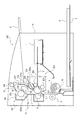
図11は、電子写真方式や他の記録方式を採用する画像形成装置300の一例としてにレーザビームプリンタからなる画像形成装置300の構成を示す。図11に示す画像形成装置300においては、普通紙その他の記録材Pを載置しておく給送トレイ3を有する。この給送トレイ3から給送ローラ4等を含む給送部により画像形成装置300内に記録材Pを給送する。そして、転写ローラ6が設けられた転写部において該記録材Pにトナー像を転写する。その後、定着装置100において記録材P上のトナー像を加熱及び加圧することにより熱定着する。その後、排出ローラ104により画像形成装置300本体の上方側に設けられた排出トレイ8上に記録材Pが排出される。
FIG. 11 shows a configuration of an
図11に示すように、画像形成装置300においては、給送トレイ3に積載された最上部の記録材Pが給送ローラ4によって繰り出され、分離パッド10との協働により一枚ずつ分離給送される。その後、記録材Pの搬送方向下流にレジストローラ5、感光ドラム201の表面と転写ローラ6とのニップ部からなる転写ニップ部Tが順次配置される。そして、内部に加熱源であるヒータ105を備えた加熱手段となる定着フィルム103と、加圧手段である加圧ローラ102とのニップ部からなる定着ニップ部Nにトナー像を担持した記録材Pが順次搬送される。
As shown in FIG. 11, in the
これにより記録材Pの給送と、感光ドラム201の表面上に形成されたトナー像の記録材Pへの転写及び記録材P上のトナー像の熱定着が順次行われ、その後、記録材Pは、排出ローラ104により排出トレイ8上に排出される。このような画像形成装置300においては、ヒータ105により加熱された記録材Pから発生する水蒸気に起因する周辺部品への結露を防止する必要がある。このため特許文献1では、図11に示す比較例の画像形成装置300のように、定着ニップ部Nから送り出される記録材Pを上方から案内する搬送ガイド13に水蒸気を上方に逃がす通路としての貫通穴からなる開口14を設けている。
Thus, the feeding of the recording material P, the transfer of the toner image formed on the surface of the
しかしながら、図12に示すように、図11に示す画像形成装置300がエアーコンディショナー(エアコン)や扇風機等の送風装置12の近辺で使用された場合、該送風装置12から定着ニップ部Nの方向に風が吹き付けられる場合がある。その場合は、ヒータ105により加熱された記録材Pから発生した水蒸気が定着ニップ部Nよりも記録材Pの搬送方向上流側へ逆流することがある。
However, as shown in FIG. 12, when the
図12は、記録材Pが転写ニップ部T、定着ニップ部N、排出ローラ104によりそれぞれ挟持されている状態を示す。図12に示す空間S1,S2は、定着ニップ部Nよりも記録材Pの搬送方向下流に形成された空間である。定着ニップ部Nを通過した後の記録材Pからは該記録材Pに含まれていた水分が定着ニップ部Nにおいてヒータ105により加熱されることで水蒸気になり空間S1,S2を満たす。この状態において画像形成装置300が送風装置12の近辺で使用された場合、該送風装置12により加圧ローラ102と定着フィルム103との近傍に風が吹き付けられることがある。
FIG. 12 shows a state where the recording material P is nipped by the transfer nip T, the fixing nip N, and the
図12は、排出ローラ104と、定着フィルム103を覆うカバー107との隙間から吹き込む風の経路D1を示す。更に、画像形成装置300の上方から搬送ガイド13に設けられた開口14を介して加圧ローラ102と、カバー106との隙間から吹き込む風の経路D2とを示す。このような風の経路D1,D2を経由して空間S1,S2を満たしていた水蒸気が感光ドラム201の表面に吹き付けられる。その結果、感光ドラム201の表面に水蒸気が付着し、該感光ドラム201の表面上の電位が乱されて該感光ドラム201の表面上にトナー像を良好に形成することができなくなる。その結果、画像不良となってしまうといった問題があった。
FIG. 12 shows a path D1 of wind blown from a gap between the
本発明は前記課題を解決するものであり、その目的とするところは、記録材から発生する水蒸気により像担持体が結露することを防止する画像形成装置を提供するものである。 SUMMARY OF THE INVENTION The present invention has been made to solve the above-described problems, and an object of the present invention is to provide an image forming apparatus that prevents dew condensation on an image carrier due to water vapor generated from a recording material.
前記目的を達成するための本発明に係る画像形成装置の代表的な構成は、感光体と、画像情報に応じて前記感光体にトナー画像を形成する画像形成部と、前記感光体に形成されたトナー画像が転写された記録材を定着ニップ部で挟持搬送しつつ加熱し、記録材にトナー画像を定着する定着ユニットであって、記録材に定着される前の記録材上のトナー画像と接触する第一の回転体と、前記第一の回転体と共に前記定着ニップ部を形成する第二の回転体と、前記第二の回転体の回転軸線方向に見た時に前記第一の回転体の周面の一部を覆うように設けられている第一のカバー部材及び前記第二の回転体の周面の一部を覆うように設けられている第二のカバー部材と、第二のカバー部材に取り付けられており記録材を前記定着ニップ部へ案内するガイド部材と、を有し、前記回転軸線方向に見た時に、前記第一のカバー部材の記録材搬送方向の上流側の端部と前記ガイド部材の間に、前記定着ニップ部へ向かう記録材が通過する空間である定着ユニットの入り口が形成されており、前記第一のカバー部材の記録材搬送方向の上流側の端部と前記第一の回転体との間には前記第一のカバー部材の記録材搬送方向の上流側の端部と前記ガイド部材の間の間隔である前記入り口の間隔よりも狭い間隔の第一の空間が形成されており、前記ガイド部材の前記第二の回転体に最も近い部分と前記第二の回転体との間には前記入り口の間隔よりも狭い間隔の第二の空間が形成されている定着ユニットと、を有し、記録材にトナー画像を形成する画像形成装置において、鉛直方向において前記定着ユニットは前記感光体よりも上方に設けられており、前記第一のカバー部材には、鉛直方向において前記感光体と前記定着ニップ部との間の高さの位置に、前記定着ユニットの内部と外部を結ぶ空気流路となる少なくとも一つの第一の開口が設けられており、前記第二のカバー部材には、鉛直方向において前記感光体と前記定着ニップ部との間の高さの位置に前記定着ユニットの内部と外部を結ぶ空気流路となる少なくとも一つの第二の開口が設けられていることを特徴とする。 A typical configuration of the image forming apparatus according to the present invention for achieving the above object includes a photoconductor, an image forming unit that forms a toner image on the photoconductor according to image information, and a photoconductor formed on the photoconductor. A fixing unit that fixes the toner image on the recording material by heating the recording material onto which the transferred toner image has been transferred while nipping and conveying the recording material at the fixing nip portion. A first rotating body that contacts, a second rotating body that forms the fixing nip portion together with the first rotating body, and the first rotating body when viewed in a rotation axis direction of the second rotating body. A first cover member provided to cover a part of the peripheral surface of the second rotating member, and a second cover member provided to cover a part of the peripheral surface of the second rotating body; The recording material is attached to the cover member and guides the recording material to the fixing nip. And a guide member between the guide member and the upstream end of the first cover member in the recording material conveyance direction when viewed in the rotation axis direction. An entrance of the fixing unit, which is a space through which the first cover member passes, is formed between an end of the first cover member on the upstream side in the recording material conveyance direction and the first rotating body. A first space with a smaller interval than the entrance, which is an interval between the upstream end of the member in the recording material conveyance direction and the guide member, is formed, and the second rotation of the guide member is performed. A fixing unit in which a second space having a smaller interval than the entrance is formed between a portion closest to the body and the second rotating body, and a toner image is formed on a recording material. The fixing unit in the vertical direction. The fixing member is provided above the photoconductor, and the first cover member has a position at a height between the photoconductor and the fixing nip portion in a vertical direction, and the inside of the fixing unit. At least one first opening serving as an air flow path connecting the outside is provided, and the second cover member is provided at a position at a height between the photoconductor and the fixing nip portion in a vertical direction. At least one second opening serving as an air flow path connecting the inside and the outside of the fixing unit is provided .
本発明によれば、記録材から発生する水蒸気により像担持体が結露することを防止することができる。 According to the present invention, it is possible to prevent the image carrier from being dewed by water vapor generated from the recording material.
図により本発明に係る搬送装置及びこれを備えた画像形成装置の一実施形態を具体的に説明する。 An embodiment of a transport device according to the present invention and an image forming apparatus including the transport device will be specifically described with reference to the drawings.
先ず、図1〜図6を用いて本発明に係る搬送装置及びこれを備えた画像形成装置の第1実施形態の構成について説明する。 First, the configuration of a transport apparatus according to the present invention and an image forming apparatus including the transport apparatus according to a first embodiment will be described with reference to FIGS.
<画像形成装置>
図1は、本発明に係る搬送装置及びこれを備えた画像形成装置の第1実施形態の構成を示す断面説明図である。尚、画像形成装置300の構成と、画像形成プロセス、及び記録材Pの給送開始から排出までの構成は、図11に示して前述した比較例と同様であるため重複する説明は省略する。また、図11及び図12に示して前述した比較例と同様に構成したものは同一の符号、或いは符号が異なっても同一の部材名を付して重複する説明を省略する。図1に示す本実施形態の画像形成装置300は、電子写真方式で転写式の画像形成プロセスを利用したレーザビームプリンタの一例である。
<Image forming apparatus>
FIG. 1 is an explanatory cross-sectional view illustrating a configuration of a first embodiment of a transport device according to the present invention and an image forming apparatus including the transport device. Note that the configuration of the
図1に示す本実施形態において、現像剤像(トナー像)を担持可能な像担持体となる感光ドラム201は、電子写真感光体からなり、図1の矢印a方向に所定の周速度で回転駆動される。感光ドラム201は、図1の矢印a方向の回転過程において、その表面が帯電手段となる帯電ローラ202により所定の極性の電位に一様に帯電処理される。次に、感光ドラム201の帯電処理面に対して像露光手段となるレーザスキャナ1から出力される画像情報の時系列電気デジタル画素信号に対応して変調されたレーザ光2による走査露光がなされる。これにより感光ドラム201の表面上に画像情報に対応した静電潜像が形成される。
In the embodiment shown in FIG. 1, a
次に、感光ドラム201の表面上に形成された静電潜像に対して現像手段となる現像ローラ203により図示しないネガ(負極性)トナーで反転現像(レーザ光2が照射された露光部にトナーが付着する)されてトナー像として顕像化される。
Next, the electrostatic latent image formed on the surface of the
一方、給送トレイ3に積載されている記録材Pが給送ローラ4により繰り出され、分離パッド10との協働作用により記録材Pが一枚ずつ分離給送される。その後、記録材Pの先端部が一旦停止したレジストローラ5のニップ部に突き当たり、該記録材Pの腰の強さにより斜行が補正される。その後、記録材Pは、所定のタイミングでレジストローラ5により挟持搬送されて感光ドラム201と、該感光ドラム201に対向して設けられた転写手段となる転写ローラ6とにより形成される圧接ニップ部である転写ニップ部Tに搬送される。そして、転写ローラ6に所定の転写バイアス電圧が印加されることにより感光ドラム201の表面上に形成されたトナー像が記録材Pに転写される。
On the other hand, the recording material P stacked on the
転写ニップ部Tを通過した記録材Pは、感光ドラム201の表面から分離される。その後、記録材Pは、図1に示す搬送ガイド7により案内されて定着ニップ部Nに導かれる。定着ニップ部Nは、定着手段となる定着装置100に設けられた記録材Pを加熱する加熱手段となる定着フィルム103と、該定着フィルム103に圧接する加圧手段となる加圧ローラ102とのニップ部により形成される。
The recording material P that has passed through the transfer nip T is separated from the surface of the
搬送ガイド7よりも記録材Pの搬送方向下流で、且つ定着ニップ部Nよりも記録材Pの搬送方向上流には、該定着ニップ部Nに記録材Pを案内する第一のガイド部材となる前ガイド101が設けられている。前ガイド101と、定着フィルム103を保護する第一の保護部材となるカバー107との間には、記録材Pの搬送路となる図3に示す空間S3が形成される。感光ドラム201の表面と、転写ローラ6の表面とにより挟持搬送される記録材Pは以下の通りである。空間S3(搬送路)を通って定着装置100の加圧部材である弾性を有する加圧ローラ102と、円筒状の定着フィルム103とにより形成される定着ニップ部Nに搬送される。
A first guide member that guides the recording material P to the fixing nip portion N downstream of the
トナー像を担持した記録材Pは、定着ニップ部Nを通過する過程において加熱及び加圧されてトナーが熱溶融して記録材Pに熱定着される。感光ドラム201は、定着ニップ部Nよりも記録材Pの搬送方向上流に設けられる。その後、排出ローラ104により挟持搬送されて排出トレイ8上に排出される。記録材Pが分離された後の感光ドラム201の表面に残留した転写残トナー等の付着残留汚染物は、クリーニング手段となるクリーニングブレード204により掻き取られて除去され、感光ドラム201の表面が清掃される。
The recording material P carrying the toner image is heated and pressed in the process of passing through the fixing nip N, so that the toner is melted by heat and thermally fixed to the recording material P. The
本実施形態の画像形成装置300本体には、図示しないガイドレールに沿ってプロセスカートリッジ200が着脱及び交換可能に設けられている。プロセスカートリッジ200は、感光ドラム201、帯電ローラ202、現像ローラ203、クリーニングブレード204等が一体的に設けられている。図4(a),(b)に示すように、プロセスカートリッジ200の枠体200aには、シャッタ部材として構成される保護部材205が開閉可能に設けられている。
In the main body of the
プロセスカートリッジ200が画像形成装置300本体外にある際には以下の通りである。図4(a)に示すように、保護部材205がプロセスカートリッジ200の枠体200aに設けられた開口200bから一部が転写ローラ6に対向して露出する感光ドラム201の表面を覆って感光を防止する。
When the
一方、プロセスカートリッジ200が画像形成装置300本体に装着されると、保護部材205が図4(b)の矢印b方向に移動して転写ローラ6に対向する感光ドラム201の表面を開口200bから露出させる。本実施形態の保護部材205は、遮蔽部材として感光防止部材からなる。図3に示すように、本実施形態の保護部材205(遮蔽部材)は、感光ドラム201の表面と、カバー107(第一の保護部材)との間に設けられる。
On the other hand, when the
プロセスカートリッジ200が画像形成装置300本体から取り外されたとき、保護部材205は、図4(a)に示すように、開口200bから露出した感光ドラム201の表面を覆って保護した状態となる。また、プロセスカートリッジ200が画像形成装置300本体に挿入された際には、図示しない移動手段により保護部材205は、図4(b)の矢印b方向に移動して図4(b)に示すように、感光ドラム201の表面を開口200bから露出させた状態となる。
When the
図1に示す画像形成装置300の本体フレーム9(外装部材)は、定着装置100やレーザスキャナ1等の各種装置を支持する。本体フレーム9は、プロセスカートリッジ200を着脱する際のガイド部材も兼ねている。図5に示すように、画像形成装置300の本体フレーム9(外装部材)の一部は、加圧ローラ102(加圧手段)を保護するカバー106(第二の保護部材)の該加圧ローラ102とは反対側に設けられている。
The main body frame 9 (exterior member) of the
<搬送装置>
次に、図5を用いて本実施形態における搬送装置11の構成について説明する。図5は、本実施形態における搬送装置11の構成を示す断面説明図である。図5において、加圧ローラ102は、本体フレーム9に設けられた図示しない軸受部材により回動可能に支持される。定着フィルム103(加熱手段)は、円筒状で構成され、内部に加熱体であるヒータ105が図示しない保持部材に取り付けられている。
<Transport device>
Next, the configuration of the
また、定着フィルム103は、図示しないフランジ部材に対して回動可能に支持される。加圧ローラ102と定着フィルム103及びヒータ105は、該定着フィルム103を挟んでヒータ105の表面と加圧ローラ102との間に熱定着に必要な所定幅の定着ニップ部Nが形成され、図示しない付勢手段により所定の加圧力で圧接されている。
The fixing
加圧ローラ102は、図示しない駆動源から回転駆動力が伝達されて図5の矢印c方向に回転駆動される。加圧ローラ102の回転により該加圧ローラ102と圧接された定着フィルム103が図5の矢印d方向に従動回転する。加圧ローラ102の外周部を保護するカバー106(第二の保護部材)と、定着フィルム103の外周部を保護するカバー107(第一の保護部材)とにより定着装置100の外装カバーが構成されている。これにより高温になる定着装置100の各構成部品にユーザが触れることを防止する。
The
図5に示す定着装置100において、加圧ローラ102が回転駆動され、定着フィルム103がヒータ105が設けられた図示しないフランジ部材の外周を従動回転する。そして、ヒータ105に通電されて該ヒータ105が発熱する。これにより定着ニップ部Nの温度が所定温度(例えば、150℃以上)に昇温して温調される。その状態において、定着ニップ部Nに未定着トナー像を担持した記録材Pが搬送される。そして、該定着ニップ部Nにおいて、記録材Pに担持された未定着トナー像が定着フィルム103の外周面に密着して該定着フィルム103と一緒に定着ニップ部Nを挟持搬送されていく。
In the
未定着トナー像を担持した記録材Pが定着ニップ部Nを搬送される過程において、ヒータ105の熱が定着フィルム103を介して記録材P上に担持された未定着トナーに付与される。これにより記録材P上の未定着トナーが加熱及び圧力されることで熱溶融して軟化し、記録材Pにトナー像が熱定着される。トナー像が熱定着された記録材Pが定着ニップ部Nを通過すると、該定着フィルム103の外周面から曲率分離されて排出ローラ104により挟持搬送されて排出トレイ8上に排出される。
In the process in which the recording material P carrying the unfixed toner image is conveyed through the fixing nip N, the heat of the
<水蒸気対策>
次に、図2及び図3を用いて、ヒータ105により加熱された記録材Pから発生する水蒸気対策について説明する。先ず、定着装置100のカバー107(第一の保護部材)に設けられた貫通穴からなる開口107A(第一の開口)と、カバー106(第二の保護部材)に設けられた貫通穴からなる開口106A(第二の開口)との位置関係について説明する。
<Steam measures>
Next, a countermeasure against water vapor generated from the recording material P heated by the
図3に示すように、開口107A(第一の開口)は、カバー107に感光ドラム201と定着ニップ部Nとの間で、且つ、第一の空間K1よりも記録材Pの搬送方向下流に設けられた貫通穴からなる。一方、開口106A(第二の開口)は、カバー106に感光ドラム201と定着ニップ部Nとの間で、且つ、第二の空間K2よりも記録材Pの搬送方向下流に設けられた貫通穴からなる。
As shown in FIG. 3, the
図2(a),(b)は、本実施形態の定着装置100と、記録材Pに画像(トナー像)を形成する画像形成手段となるプロセスカートリッジ200の構成を示す斜視説明図である。図3は、本実施形態の定着装置100とプロセスカートリッジ200の構成を示す断面説明図である。尚、図2及び図3では、開口106A,107Aの位置関係を分かり易く説明するために搬送ガイド7等を省略している。図2及び図3に示すように、本実施形態では、ヒータ105により加熱された記録材Pから発生する水蒸気対策として、定着フィルム103の外周部を保護するカバー107に開口107Aを設ける。更に、加圧ローラ102の外周部を保護するカバー106に開口106Aを設ける。
FIGS. 2A and 2B are perspective explanatory diagrams illustrating the configuration of the fixing
図3に示す本実施形態の搬送装置11において、定着ニップ部Nよりも記録材Pの搬送方向上流に設けられ、カバー107と定着フィルム103との間に形成される第一の空間K1における間隔Xは以下の通り設定される。ヒータ105により加熱されて高温になる定着フィルム103にユーザが触れないようにするために狭い間隔Xで、且つ、記録材Pの搬送路となる空間S3における間隔Wよりも狭い(小さい)間隔X(例えば、間隔X=2mm〜4mm程度)に設定されている。
In the
第一の空間K1における間隔Xは、定着フィルム103の軸方向において、該定着フィルム103とカバー107との間の第一の空間K1の全域に亘って設定されている。カバー107に設けられる貫通穴からなる開口107Aの位置は以下の通り設定される。図3に示すように、感光ドラム201の回転中心102aと、定着ニップ部Nの中心N1とを通り、該定着ニップ部Nの接線Lに対して垂直な直線Mと、感光ドラム201との間の領域に設けられる。また、開口107A(第一の開口)の面積は、100mm2以上、且つ300mm2以下の範囲になるように設定されている。
The interval X in the first space K1 is set over the entire area of the first space K1 between the fixing
一方、図3に示す本実施形態の搬送装置11において、定着ニップ部Nよりも記録材Pの搬送方向上流には、加圧ローラ102の表面と、前ガイド101との間に形成される第二の空間K2が設けられる。加圧ローラ102と、定着ニップ部Nよりも記録材Pの搬送方向上流に配置される前ガイド101との間に形成される第二の空間K2における間隔Yは以下の通り設定される。定着ニップ部Nへの記録材Pの先端部の導入をスムーズにするために狭い間隔Yで、且つ、記録材Pの搬送路となる空間S3における間隔Wよりも狭い(小さい)間隔Y(例えば、間隔Y=1.5mm〜5mm程度)に設定されている。
On the other hand, in the
第二の空間K2における間隔Yは、加圧ローラ102の軸方向において、該加圧ローラ102と、定着ニップ部Nよりも記録材Pの搬送方向上流に配置される前ガイド101との間に形成される第二の空間K2の全域に亘って設定されている。カバー106に設けられる貫通穴からなる開口106Aの位置は、図3に示す感光ドラム201と、前述した直線Mとの間の領域に設けられる。
The interval Y in the second space K2 is between the
また、本実施形態において、開口106A(第二の開口)の面積は、100mm2以上、且つ300mm2以下の範囲になるように設定されている。本実施形態の定着装置100は、図3に示すように、定着フィルム103と、加圧ローラ102と、カバー106,107と、前ガイド101と、搬送路となる空間S3と、第一の空間K1と、第二の空間K2とを有して構成される。
In the present embodiment, the area of the
次に、図3に示す本実施形態の搬送装置11において、保護部材205と開口107Aとの位置関係について説明する。カバー107と保護部材205との位置関係は、図3に示すように、開口107A(第一の開口)よりも記録材Pの搬送方向上流でカバー107と保護部材205との間に第三の空間K3が形成される。
Next, the positional relationship between the
第三の空間K3よりも記録材Pの搬送方向下流(図3の上方)でカバー107と保護部材205との間に該第三の空間K3における間隔Zよりも広い間隔Vを有してカバー107と保護部材205との間に形成された第四の空間K4を有する。第四の空間K4は、該第三の空間K3に連通すると共に、該第三の空間K3における間隔Zよりも広い間隔Vを有し、感光ドラム201とは反対方向に向かって該間隔Vが広がる構成を有する。
The cover having a wider interval V than the interval Z in the third space K3 between the
本実施形態の保護部材205(遮蔽部材)は、感光ドラム201を保護する第三の保護部材として構成される。本実施形態の保護部材205(第三の保護部材)は、図4(a),(b)に示すように、プロセスカートリッジ200の枠体200aに対して開閉可能に設けられたシャッタ部材として構成されている。
The protection member 205 (shielding member) of the present embodiment is configured as a third protection member for protecting the
本実施形態では、図3に示すように、プロセスカートリッジ200が画像形成装置300本体に装着されて保護部材205が開放された状態において以下の通りである。保護部材205とカバー107との間に形成される第三の空間K3における間隔Z(隙間)は、0.5mm以上、且つ3.5mm以下の範囲になるように設定されている。第三の空間K3における間隔Zは、定着フィルム103及び感光ドラム201の軸方向において、カバー107と保護部材205との間に形成される第三の空間K3の全域に亘って設定されている。
In the present embodiment, as shown in FIG. 3, the process is performed as follows in a state where the
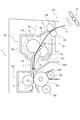
次に、図6を用いて、本実施形態における水蒸気対策によってヒータ105により加熱された記録材Pから発生する水蒸気が感光ドラム201の表面に水滴となって付着することによる画像不良を改善するメカニズムについて説明する。図6は、本実施形態における水蒸気対策効果を説明する断面説明図である。図6は、搬送途中の記録材Pが定着ニップ部Nと転写ニップ部Tとでそれぞれ挟持されている状態を示す。
Next, referring to FIG. 6, a mechanism for improving image defects due to water vapor generated from the recording material P heated by the
図6に示すように、画像形成装置300が送風装置12の付近で使用された場合、送風装置12から定着装置100の定着ニップ部Nに向かって風が吹き付けられることがある。その場合、送風装置12から吹き付けられる風が経路D1,D2を通って、ヒータ105により加熱された記録材Pから発生する水蒸気で満たされている空間S1,S2を通る。これにより風は水蒸気を含む。
As illustrated in FIG. 6, when the
本実施形態では、加圧ローラ102の外周部を保護するカバー106に開口106Aを設ける。更に、定着フィルム103の外周部を保護するカバー107に開口107Aを設ける。そして、各開口106A,107Aが前述した位置関係に設定されている。これにより図6に示すように、経路D1,D2から侵入してくる風は、それぞれ各開口106A,107Aにより形成された経路D1a,D2aを通って感光ドラム201に至る経路から外れる。これにより感光ドラム201の表面に結露することがなくなり、その結果、画像不良が発生することがない。
In the present embodiment, an
また、風の吹き込み方向においてカバー107に形成した開口107Aと感光ドラム201との間に保護部材205を配置する。そして、開口107Aと保護部材205との間の第三の空間K3に連続するとともに、該第三の空間K3の記録材Pの搬送方向下流(図6の上方)に該第三の空間K3における間隔Zよりも広い間隔Vを有する第四の空間K4を設ける。これにより図6に示す経路D1から侵入する風が開口107Aからなる経路D1aを通って第三の空間K3における間隔Zよりも広い間隔Vを有する第四の空間K4に抜ける。これにより通気抵抗が大きい第三の空間K3を通過して保護部材205に沿って感光ドラム201に向かう風を低減するができる。
In addition, the
一方、図4(b)の矢印a方向に回転する感光ドラム201の表面に接触するクリーニングブレード204や現像ローラ203等の摩擦により発熱して昇温する。しかし、保護部材205は、それらの部品から離れているため昇温し難い。
On the other hand, heat is generated by friction of the
また、保護部材205は、図4(a),(b)に示すように、プロセスカートリッジ200の枠体200aに対して開閉可能に支持されている。これによりプロセスカートリッジ200の枠体200a内部の熱が保護部材205に伝わり難い。これにより保護部材205は、低い温度を保っている。従って、図6に示すカバー107に形成した開口107Aからなる経路D1aを通って排気された水蒸気を含む風が保護部材205に吹き付けられたときに該水蒸気を保護部材205の表面に結露させることができる。
Further, as shown in FIGS. 4A and 4B, the
これにより感光ドラム201の表面に水蒸気が回りこむことを防止することができる。このとき、保護部材205の表面に結露した水滴が自重により感光ドラム201の表面に落下することを防止する。このために本実施形態では、図6に示すように、保護部材205の感光ドラム201側の端部に感光ドラム201の軸方向の全長に亘って防護壁205Aを設けている。
Accordingly, it is possible to prevent water vapor from flowing around the surface of the
尚、防護壁205Aの代わりに保護部材205の感光ドラム201側の端部に該感光ドラム201の軸方向の全長に亘って溝部を形成し、保護部材205の表面に結露した水滴が自重により該溝部内に落下して該水滴を保持する構成でも良い。これにより保護部材205の表面に結露した水滴が自重により感光ドラム201の表面に落下することを防止することができる。また、防護壁205Aや溝部は、保護部材205の図6の左右方向において複数設けることでも良い。
In addition, instead of the
ここで、定着フィルム103の外周部を保護するカバー107に形成した開口107A(第一の開口)の面積が100mm2よりも小さい場合は以下の通りである。図6に示す経路D1から侵入してくる風を開口107Aから十分に排気することができなくなる。
Here, the case where the area of the
また、開口107Aの面積が300mm2よりも大きい場合は、ヒータ105により加熱された定着装置100から排気される高温の風が開口107Aを通過して画像形成装置300本体内に多量に充満することになる。これによりプロセスカートリッジ200が高温になることで画像形成プロセスに悪影響をもたらす可能性もある。従って、カバー107に形成した開口107Aの面積は、100mm2以上、且つ300mm2以下の範囲で設定することが事実上適切であった。
When the area of the
また、本実施形態の開口107Aは以下の通りである。図2(a)に示すように、カバー107の長手方向(定着フィルム103の軸方向)に沿って該開口107Aの総面積が100mm2以上、且つ300mm2以下の範囲内となるように三箇所に設けた一例である。他に、開口107Aの総面積が100mm2以上、且つ300mm2以下の範囲内となるように一箇所、或いは、他の複数箇所に設けることでも良い。
The
また、加圧ローラ102の外周部を保護するカバー106に形成した開口106A(第二の開口)の面積が100mm2よりも小さい場合は以下の通りである。図6に示す経路D2から侵入してくる風を開口106Aから十分に排気することができなくなる。また、開口106Aの面積が300mm2よりも大きい場合は、加圧ローラ102の温度上昇が所定温度よりも下回り、記録材P上の未定着トナーの定着が不十分になる可能性がある。
The case where the area of the
従って、開口106Aの面積は、100mm2以上、且つ300mm2以下の範囲で設定することが事実上適切であった。また、本実施形態の開口106Aは以下の通りである。図2(b)に示すように、カバー106の長手方向(加圧ローラ102の軸方向)に沿って該開口106Aの総面積が100mm2以上、且つ300mm2以下の範囲内となるように三箇所に設けた一例である。他に、開口106Aの総面積が100mm2以上、且つ300mm2以下の範囲内となるように一箇所、或いは、他の複数箇所に設けることでも良い。
Therefore, it was practically appropriate to set the area of the
また、図6に示す保護部材205とカバー107とにより形成される第三の空間K3における間隔Zが0.5mmよりも小さい場合は以下の通りである。プロセスカートリッジ200を画像形成装置300本体に対して着脱する。その際にプロセスカートリッジ200の枠体200aに対して開閉可能に設けられた保護部材205と、画像形成装置300本体側に設けられたカバー107とが衝突する可能性があり、部品の破損等の懸念がある。
The case where the interval Z in the third space K3 formed by the
また、第三の空間K3における間隔Zが3.5mmよりも大きい場合は、図6に示すカバー107に形成した開口107Aからなる経路D1aから感光ドラム201の表面に向かって侵入してくる風を遮蔽する効果が得られなくなる。従って、図6に示す保護部材205とカバー107とにより形成される第三の空間K3における間隔Z(隙間)は、0.5mm以上、且つ3.5mm以下の範囲で設定することが事実上適切であった。
When the interval Z in the third space K3 is larger than 3.5 mm, the wind entering the surface of the
本実施形態によれば、送風装置12により定着装置100の定着ニップ部Nに風が吹き付けられた場合でもヒータ105により加熱された記録材Pから発生する水蒸気により感光ドラム201の表面が結露することを防止することができる。これにより感光ドラム201の表面が結露することによる画像不良を抑制することができる。
According to the present embodiment, even when air is blown to the fixing nip portion N of the fixing
次に、図7及び図8を用いて本発明に係る搬送装置及びこれを備えた画像形成装置の第2実施形態の構成について説明する。尚、前記第1実施形態と同様に構成したものは同一の符号、或いは符号が異なっても同一の部材名を付して説明を省略する。 Next, the configuration of a second embodiment of the transport device according to the present invention and an image forming apparatus including the transport device will be described with reference to FIGS. The same components as those in the first embodiment have the same reference numerals or the same reference numerals, even if the reference numerals are different.
本実施形態では、図7に示すように、図6に示す前記第1実施形態の搬送装置11において、感光ドラム201の近傍(転写ニップ部Tの近傍)で、転写ニップ部Tよりも記録材Pの搬送方向下流には、第二のガイド部材となる搬送ガイド7が設けられている。搬送ガイド7には、貫通穴からなる開口7A(第三の開口)が設けられている。開口7A(第三の開口)の面積は、600mm2以上、且つ900mm2以下の範囲に設定されている。
In the present embodiment, as shown in FIG. 7, in the
次に、図7を用いて本実施形態における水蒸気対策について説明する。図7に示すように、経路D2から通ってくる風量が所定の風量よりも多い場合は以下の通りである。ヒータ105により加熱された記録材Pから発生する水蒸気を含んだ風が加圧ローラ102の外周部を保護するカバー106に形成した貫通穴からなる開口106Aから排気しきれない場合がある。開口106Aから排気しきれない風は、第二の空間K2通って搬送中の記録材Pの片側の面(加圧ローラ102及び転写ローラ6が配置される側の面)に沿って転写ニップ部Tに至る場合がある。その結果、感光ドラム201の表面が結露することにより画像不良となる場合があった。
Next, a countermeasure against water vapor in the present embodiment will be described with reference to FIG. As shown in FIG. 7, the case where the air volume coming from the route D2 is larger than the predetermined air volume is as follows. In some cases, wind containing water vapor generated from the recording material P heated by the
本実施形態では、図7に示すように、転写ニップ部Tよりも記録材Pの搬送方向下流で該転写ニップ部Tの近傍に搬送ガイド7(第二のガイド部材)を設けている。そして、該搬送ガイド7に開口7Aを設けている。これによりヒータ105により加熱された記録材Pから発生する水蒸気を含む風は、該開口7Aにより形成される経路D2bを通って記録材Pの搬送路から外に排気される。これにより感光ドラム201の表面が結露することがなくなる。その結果、感光ドラム201の表面が結露することによる画像不良が発生することがなくなる。
In the present embodiment, as shown in FIG. 7, a transport guide 7 (second guide member) is provided near the transfer nip T downstream of the transfer nip T in the transport direction of the recording material P. The
また、搬送ガイド7に設けられる開口7A(第三の開口)の面積が600mm2よりも小さい場合は、図7に示す経路D2から侵入してくる風を搬送ガイド7に設けられた開口7Aから十分に排気することができなくなる。
When the area of the
また、該開口7Aの面積が900mm2よりも大きい場合は以下の通りである。搬送される記録材Pと、任意の搬送ガイドとの摺擦によって発生する摺擦音が画像形成装置300本体の外に漏れ出ることでユーザの使用環境に対して悪影響を及ぼす可能性がある。従って、搬送ガイド7に設けられる開口7Aの面積は、600mm2以上、且つ900mm2以下の範囲に設定することが事実上適切であった。
The case where the area of the
また、本実施形態の開口7Aは、図8に示すように、搬送ガイド7の長手方向(感光ドラム201及び転写ローラ6の軸方向)に沿って三箇所に設けた一例である。該開口7Aの総面積は、600mm2以上、且つ900mm2以下の範囲内となるように設定される。他に、開口7Aの総面積が600mm2以上、且つ900mm2以下の範囲内となるように一箇所、或いは、他の複数箇所に設けることでも良い。他の構成は前記第1実施形態と同様に構成され、同様の効果を得ることが出来る。
Further, as shown in FIG. 8, the
次に、図9及び図10を用いて本発明に係る搬送装置及びこれを備えた画像形成装置の第3実施形態の構成について説明する。尚、前記各実施形態と同様に構成したものは同一の符号、或いは符号が異なっても同一の部材名を付して説明を省略する。 Next, with reference to FIGS. 9 and 10, a description will be given of the configuration of a third embodiment of the transport device according to the present invention and the image forming apparatus provided with the transport device. In addition, the same components as those in the above-described embodiments are denoted by the same reference numerals or the same reference numerals even if the reference numerals are different, and the description is omitted.
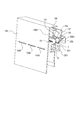
本実施形態では、図9に示すように、図7に示す前記第2実施形態の搬送装置11において、カバー106の加圧ローラ102とは反対側に画像形成装置300本体を保護する外装部材である外装カバー108が設けられている。更に、外装カバー108(外装部材)の搬送ガイド7(第二のガイド部材)に設けられた開口7A(第三の開口)よりも記録材Pの搬送方向上流には、貫通穴からなる開口108A(第四の開口)が形成されている。
In the present embodiment, as shown in FIG. 9, in the transporting
図9に示すように、外装カバー108(外装部材)に設けられた開口108A(第四の開口)は以下の通りである。加圧ローラ102の外周部を保護するカバー106(第二の保護部材)に設けられた開口106A(第二の開口)よりも記録材Pの搬送方向上流(画像形成装置300本体の下方)に配置される。本実施形態において、開口108A(第四の開口)の面積は、150mm2以上、且つ500mm2以下の範囲に設定されている。
As shown in FIG. 9, the
次に、図9を用いて本実施形態における水蒸気対策について説明する。図9に示す経路D2を通ってヒータ105により加熱された記録材Pから発生する水蒸気を含む風がカバー106に設けられた開口106Aや搬送ガイド7に設けられた開口7Aから各経路D2a,D2bを通って記録材Pの搬送路から外に排気される。その後、画像形成装置300本体を保護する外装カバー108と搬送装置11との間に形成される空間S4内で対流する。
Next, a countermeasure against water vapor in the present embodiment will be described with reference to FIG. A wind containing water vapor generated from the recording material P heated by the
このときの対流により搬送ガイド7に設けられた開口7Aから記録材Pの搬送路内に逆流する場合がある。或いは、開口7Aから経路D2bを通って空間S4内に排気される風の妨げとなることがある。その結果、ヒータ105により加熱された記録材Pから発生する水蒸気を含む風が感光ドラム201の表面に到達し、感光ドラム201の表面が結露することにより画像不良が発生する場合があった。
The convection at this time may cause the recording material P to flow back into the conveyance path of the recording material P from the
本実施形態では、図9に示すように、外装カバー108に開口106A,7Aよりも記録材Pの搬送方向上流(画像形成装置300本体の下方)に開口108Aを設けてある。これにより経路D2a,D2bから空間S4内に排気された水蒸気を含む風は以下の通りである。外装カバー108と搬送装置11との間に形成される空間S4を通る経路D3を通って画像形成装置300本体の下方に流れる風と共に、外装カバー108に形成された開口108Aからなる経路D2cを通って画像形成装置300本体の外に排気される。
In the present embodiment, as shown in FIG. 9, an
これにより経路D2a,D2bから空間S4内に排気された風が対流して開口7Aに逆流することもなく、経路D2bから空間S4内に排気されてくる水蒸気を含む風の流れを妨げることがなくなる。
Thus, the wind exhausted into the space S4 from the routes D2a and D2b does not convect and flow back to the
また、外装カバー108に形成された開口108A(第四の開口)の面積が150mm2よりも小さい場合は、図9に示す経路D2a,D2bから空間S4内に排気されてくる風を開口108Aから十分に排気することができなくなる。
When the area of the
また、開口108A(第四の開口)の面積が500mm2よりも大きい場合は以下の通りである。搬送される記録材Pと任意の搬送ガイドとの摺擦によって発生する摺擦音が画像形成装置300本体の外に漏れ出ることでユーザの使用環境に対して悪影響を及ぼす可能性がある。従って、開口108A(第四の開口)の面積は、150mm2以上、且つ500mm2以下の範囲に設定することが事実上適切であった。
The case where the area of the
また、本実施形態の開口108A(第四の開口)は、図10に示すように、外装カバー108の水平方向(感光ドラム201及び転写ローラ6の軸方向)に沿って三箇所に設けた一例である。該開口108Aの総面積は、150mm2以上、且つ500mm2以下の範囲内となるように設定される。他に、開口108Aの総面積が150mm2以上、且つ500mm2以下の範囲内となるように一箇所、或いは、他の複数箇所に設けることでも良い。他の構成は前記各実施形態と同様に構成され、同様の効果を得ることが出来る。
Further, as shown in FIG. 10, the
<その他>
前記各実施形態では、感光ドラム201(像担持体)と、定着フィルム103(加熱手段)との間に設ける遮蔽部材の一例としてプロセスカートリッジ200に対して開閉可能に設けた保護部材205の一例について説明した。他に、前記遮蔽部材をプロセスカートリッジ200ではなく、画像形成装置300の本体フレームに取り付けられる別部材で構成することも出来る。また、定着装置100は、定着フィルム103(加熱手段)と、加圧ローラ102(加圧手段)とを用いたフィルム加熱方式のものに限られるものではなく、定着ローラ(加熱手段)と、加圧ローラ(加圧手段)とからなる熱ローラ方式等で構成することも出来る。
<Others>
In the above embodiments, an example of a
また、定着装置100に設けられる加圧部材としては加圧ローラ102に限られるものではなく、該加圧ローラ102の代わりに回動ベルト体等の回転体により構成することも出来る。また、定着装置100に設けられるヒータ105(加熱体)は、電磁誘導発熱部材であっても良い。また、定着フィルム103(加熱手段)が電磁誘導発熱部材や該電磁誘導発熱部材を含む複合層からなる構造体で構成され、定着フィルム103(加熱手段)自体が発熱する構成であっても良い。また、画像形成装置300において記録材Pに対する未定着トナー像の形成原理や画像形成プロセスは、前述した各実施形態の構成に限定されるものではなく、種々の画像形成原理や画像形成プロセスに適用出来る。
Further, the pressing member provided in the
K1,K2…第一、第二の空間
N…定着ニップ部
P…記録材
S3…空間(搬送路)
W…記録材Pの搬送路となる空間S3における間隔
X…カバー107と定着フィルム103との間に形成される第一の空間K1における間隔
Y…加圧ローラ102と前ガイド101との間に形成される第二の空間K2における間隔
101…前ガイド(第一のガイド部材)
102…加圧ローラ(加圧手段)
103…定着フィルム(加熱手段)
106…カバー(第二の保護部材)
106A…開口(第二の開口)
107…カバー(第一の保護部材)
107A…開口(第一の開口)
201…感光ドラム(像担持体)
K1, K2: first and second spaces N: fixing nip P: recording material S3: space (conveyance path)
W: an interval in a space S3 serving as a conveyance path of the recording material P X: an interval in a first space K1 formed between the
102 ... Pressing roller (pressing means)
103 ... Fixing film (heating means)
106 ... Cover (second protection member)
106A: Opening (second opening)
107 ... Cover (first protection member)
107A: Opening (first opening)
201: photosensitive drum (image carrier)
Claims (9)
画像情報に応じて前記感光体にトナー画像を形成する画像形成部と、An image forming unit that forms a toner image on the photoconductor according to image information;
前記感光体に形成されたトナー画像が転写された記録材を定着ニップ部で挟持搬送しつつ加熱し、記録材にトナー画像を定着する定着ユニットであって、記録材に定着される前の記録材上のトナー画像と接触する第一の回転体と、前記第一の回転体と共に前記定着ニップ部を形成する第二の回転体と、前記第二の回転体の回転軸線方向に見た時に前記第一の回転体の周面の一部を覆うように設けられている第一のカバー部材及び前記第二の回転体の周面の一部を覆うように設けられている第二のカバー部材と、第二のカバー部材に取り付けられており記録材を前記定着ニップ部へ案内するガイド部材と、を有し、前記回転軸線方向に見た時に、前記第一のカバー部材の記録材搬送方向の上流側の端部と前記ガイド部材の間に、前記定着ニップ部へ向かう記録材が通過する空間である定着ユニットの入り口が形成されており、前記第一のカバー部材の記録材搬送方向の上流側の端部と前記第一の回転体との間には前記第一のカバー部材の記録材搬送方向の上流側の端部と前記ガイド部材の間の間隔である前記入り口の間隔よりも狭い間隔の第一の空間が形成されており、前記ガイド部材の前記第二の回転体に最も近い部分と前記第二の回転体との間には前記入り口の間隔よりも狭い間隔の第二の空間が形成されている定着ユニットと、A fixing unit for fixing a toner image to a recording material by heating the recording material onto which the toner image formed on the photosensitive member is transferred while nipping and conveying the recording material at a fixing nip portion, wherein the recording before fixing to the recording material is performed. A first rotating body that comes into contact with the toner image on the material, a second rotating body that forms the fixing nip together with the first rotating body, and when viewed in a rotation axis direction of the second rotating body. A first cover member provided to cover a part of the peripheral surface of the first rotating body and a second cover provided to cover a part of the peripheral surface of the second rotating body. And a guide member attached to the second cover member for guiding the recording material to the fixing nip portion, and the recording material transport of the first cover member when viewed in the rotation axis direction. Between the end on the upstream side in the direction and the guide member, the fixing nip An entrance of the fixing unit, which is a space through which the recording material passes, is formed, and the space between the upstream end of the first cover member in the recording material conveyance direction and the first rotating body is provided. A first space having a smaller interval than an interval between the entrances, which is an interval between the upstream end of the first cover member in the recording material conveyance direction and the guide member, is formed, and the first space of the guide member is formed. A fixing unit in which a second space having a smaller interval than the entrance is formed between a portion closest to the second rotating body and the second rotating body;
を有し、記録材にトナー画像を形成する画像形成装置において、Having an image forming apparatus for forming a toner image on a recording material,
鉛直方向において前記定着ユニットは前記感光体よりも上方に設けられており、The fixing unit is provided above the photoconductor in the vertical direction,
前記第一のカバー部材には、鉛直方向において前記感光体と前記定着ニップ部との間の高さの位置に、前記定着ユニットの内部と外部を結ぶ空気流路となる少なくとも一つの第一の開口が設けられており、The first cover member has, at a position at a height between the photoconductor and the fixing nip portion in a vertical direction, at least one first air passage serving as an air flow path connecting the inside and the outside of the fixing unit. An opening is provided,
前記第二のカバー部材には、鉛直方向において前記感光体と前記定着ニップ部との間の高さの位置に前記定着ユニットの内部と外部を結ぶ空気流路となる少なくとも一つの第二の開口が設けられていることを特徴とする画像形成装置。The second cover member has at least one second opening serving as an air flow path connecting the inside and the outside of the fixing unit at a position at a height between the photoconductor and the fixing nip portion in the vertical direction. An image forming apparatus, comprising:
前記遮蔽部材が前記感光体と前記第一のカバー部材との間に位置する時、前記第一の開口よりも記録材の搬送方向上流に形成される空間であり、前記第一のカバー部材と前記遮蔽部材とで形成される第三の空間と、前記第三の空間に連通すると共に、該第三の空間の間隔よりも広い間隔を有し、前記感光体が設けられた側とは反対方向に向かって間隔が広がる第四の空間が形成される、When the shielding member is located between the photoreceptor and the first cover member, the space is formed upstream of the first opening in the recording material conveyance direction, and the first cover member and A third space formed by the shielding member and a third space that communicates with the third space and that has an interval wider than the interval of the third space, and is opposite to the side on which the photoconductor is provided; A fourth space is formed in which the interval increases in the direction,
ことを特徴とする請求項1〜3いずれか1項に記載の画像形成装置。The image forming apparatus according to claim 1, wherein:
Priority Applications (2)
| Application Number | Priority Date | Filing Date | Title |
|---|---|---|---|
| JP2016030800A JP6672007B2 (en) | 2016-02-22 | 2016-02-22 | Image forming device |
| US15/438,020 US10185263B2 (en) | 2016-02-22 | 2017-02-21 | Image forming apparatus having a fixing portion and at least one opening for fluid communication between an inside and an outside of the fixing portion |
Applications Claiming Priority (1)
| Application Number | Priority Date | Filing Date | Title |
|---|---|---|---|
| JP2016030800A JP6672007B2 (en) | 2016-02-22 | 2016-02-22 | Image forming device |
Publications (3)
| Publication Number | Publication Date |
|---|---|
| JP2017151136A JP2017151136A (en) | 2017-08-31 |
| JP2017151136A5 JP2017151136A5 (en) | 2019-03-28 |
| JP6672007B2 true JP6672007B2 (en) | 2020-03-25 |
Family
ID=59630592
Family Applications (1)
| Application Number | Title | Priority Date | Filing Date |
|---|---|---|---|
| JP2016030800A Active JP6672007B2 (en) | 2016-02-22 | 2016-02-22 | Image forming device |
Country Status (2)
| Country | Link |
|---|---|
| US (1) | US10185263B2 (en) |
| JP (1) | JP6672007B2 (en) |
Families Citing this family (2)
| Publication number | Priority date | Publication date | Assignee | Title |
|---|---|---|---|---|
| US11254530B2 (en) | 2019-03-26 | 2022-02-22 | Toshiba Tec Kabushiki Kaisha | Sheet aligning mechanism |
| JP2021162743A (en) | 2020-04-01 | 2021-10-11 | ブラザー工業株式会社 | Fixing device and image forming apparatus |
Family Cites Families (7)
| Publication number | Priority date | Publication date | Assignee | Title |
|---|---|---|---|---|
| JP2004090221A (en) | 2002-08-29 | 2004-03-25 | Canon Inc | Heater and image forming apparatus |
| JP2006276215A (en) | 2005-03-28 | 2006-10-12 | Fuji Xerox Co Ltd | Image forming apparatus |
| JP2007079141A (en) * | 2005-09-14 | 2007-03-29 | Fuji Xerox Co Ltd | Image forming apparatus |
| JP4842662B2 (en) | 2006-02-20 | 2011-12-21 | 株式会社沖データ | Fixing apparatus and image forming apparatus |
| JP5463730B2 (en) | 2009-05-14 | 2014-04-09 | コニカミノルタ株式会社 | Image forming apparatus |
| JP5803575B2 (en) * | 2011-10-28 | 2015-11-04 | 村田機械株式会社 | Image forming apparatus |
| JP6289228B2 (en) | 2014-04-09 | 2018-03-07 | キヤノン株式会社 | Image forming apparatus and fixing device |
-
2016
- 2016-02-22 JP JP2016030800A patent/JP6672007B2/en active Active
-
2017
- 2017-02-21 US US15/438,020 patent/US10185263B2/en active Active
Also Published As
| Publication number | Publication date |
|---|---|
| US10185263B2 (en) | 2019-01-22 |
| US20170242380A1 (en) | 2017-08-24 |
| JP2017151136A (en) | 2017-08-31 |
Similar Documents
| Publication | Publication Date | Title |
|---|---|---|
| US9411275B2 (en) | Image forming apparatus having partition configured to separate air flow and sheet feeding paths | |
| JP5100228B2 (en) | Image heating device | |
| JP6230325B2 (en) | Fixing device | |
| CN106353995B (en) | Image forming apparatus with a toner supply device | |
| JP6391404B2 (en) | Fixing device | |
| US9383714B1 (en) | Cleaning apparatus for image carrier, image forming apparatus having the same, and method for cleaning image carrier | |
| JP2010085895A (en) | Fixing device and image forming apparatus | |
| US20180088499A1 (en) | Image forming apparatus | |
| JP6137912B2 (en) | Image forming apparatus | |
| JP5934153B2 (en) | Image forming apparatus | |
| JP6672007B2 (en) | Image forming device | |
| JP6178766B2 (en) | Image forming apparatus | |
| JP6289228B2 (en) | Image forming apparatus and fixing device | |
| JP2014170152A (en) | Fixing device and image forming apparatus | |
| JP2008298831A (en) | Fixing device and image forming apparatus | |
| JP6949556B2 (en) | Image forming device | |
| JP4817860B2 (en) | Fixing device | |
| JP2010256615A (en) | Image forming apparatus | |
| JP6614812B2 (en) | Image forming apparatus | |
| JP6287163B2 (en) | Conveying apparatus and image forming apparatus | |
| JP2009198847A (en) | Image forming apparatus | |
| JP5511013B2 (en) | Image forming apparatus | |
| JP5740922B2 (en) | Fixing apparatus and image forming apparatus | |
| JP7206927B2 (en) | image forming device | |
| JP6873640B2 (en) | Image forming device |
Legal Events
| Date | Code | Title | Description |
|---|---|---|---|
| A521 | Request for written amendment filed |
Free format text: JAPANESE INTERMEDIATE CODE: A523 Effective date: 20190212 |
|
| A621 | Written request for application examination |
Free format text: JAPANESE INTERMEDIATE CODE: A621 Effective date: 20190212 |
|
| A977 | Report on retrieval |
Free format text: JAPANESE INTERMEDIATE CODE: A971007 Effective date: 20191113 |
|
| A131 | Notification of reasons for refusal |
Free format text: JAPANESE INTERMEDIATE CODE: A131 Effective date: 20191119 |
|
| A521 | Request for written amendment filed |
Free format text: JAPANESE INTERMEDIATE CODE: A523 Effective date: 20200117 |
|
| TRDD | Decision of grant or rejection written | ||
| A01 | Written decision to grant a patent or to grant a registration (utility model) |
Free format text: JAPANESE INTERMEDIATE CODE: A01 Effective date: 20200204 |
|
| A61 | First payment of annual fees (during grant procedure) |
Free format text: JAPANESE INTERMEDIATE CODE: A61 Effective date: 20200304 |
|
| R151 | Written notification of patent or utility model registration |
Ref document number: 6672007 Country of ref document: JP Free format text: JAPANESE INTERMEDIATE CODE: R151 |