JP6670803B2 - refrigerator - Google Patents

refrigerator Download PDF

Info

Publication number
JP6670803B2
JP6670803B2 JP2017149597A JP2017149597A JP6670803B2 JP 6670803 B2 JP6670803 B2 JP 6670803B2 JP 2017149597 A JP2017149597 A JP 2017149597A JP 2017149597 A JP2017149597 A JP 2017149597A JP 6670803 B2 JP6670803 B2 JP 6670803B2
Authority
JP
Japan
Prior art keywords
heat insulating
insulating material
outer box
box
vacuum heat
Prior art date
Legal status (The legal status is an assumption and is not a legal conclusion. Google has not performed a legal analysis and makes no representation as to the accuracy of the status listed.)
Active
Application number
JP2017149597A
Other languages
Japanese (ja)
Other versions
JP2019027723A5 (en
JP2019027723A (en
Inventor
正康 津布久
正康 津布久
貴志 内山
貴志 内山
千喜憲 中小原
千喜憲 中小原
陽平 門傳
陽平 門傳
Current Assignee (The listed assignees may be inaccurate. Google has not performed a legal analysis and makes no representation or warranty as to the accuracy of the list.)
Hitachi Global Life Solutions Inc
Original Assignee
Hitachi Global Life Solutions Inc
Priority date (The priority date is an assumption and is not a legal conclusion. Google has not performed a legal analysis and makes no representation as to the accuracy of the date listed.)
Filing date
Publication date
Application filed by Hitachi Global Life Solutions Inc filed Critical Hitachi Global Life Solutions Inc
Priority to JP2017149597A priority Critical patent/JP6670803B2/en
Priority to CN201810182854.4A priority patent/CN109387010B/en
Priority to CN202010975075.7A priority patent/CN112013604B/en
Priority to TW107107612A priority patent/TWI689693B/en
Priority to TW108140919A priority patent/TWI734253B/en
Publication of JP2019027723A publication Critical patent/JP2019027723A/en
Publication of JP2019027723A5 publication Critical patent/JP2019027723A5/ja
Application granted granted Critical
Publication of JP6670803B2 publication Critical patent/JP6670803B2/en
Active legal-status Critical Current
Anticipated expiration legal-status Critical

Links

Images

Landscapes

  • Devices That Are Associated With Refrigeration Equipment (AREA)
  • Refrigerator Housings (AREA)

Description

本発明は、冷蔵庫に関する。   The present invention relates to a refrigerator.

特許文献1には、庫内の側面に操作パネルを設けた冷蔵庫が記載されている。この特許文献1に記載の冷蔵庫では、操作パネルの基板に発泡断熱材が侵入するのを防止するために、カバーを設けている。   Patent Literature 1 describes a refrigerator having an operation panel provided on a side surface in a refrigerator. In the refrigerator described in Patent Literature 1, a cover is provided to prevent the foamed heat insulating material from entering the substrate of the operation panel.

特開2003−176978号公報JP 2003-176978 A

しかしながら、上記特許文献1に記載の発明のように、カバーと外箱との間に発泡断熱材が介在すると、発泡断熱材の充填時にカバーが発泡圧を受けて変形する可能性がある。このため、カバーが変形しても基板に接触しないよう、カバーと基板との間のスペースに余裕をもたせる必要があった。   However, if the foamed heat insulating material is interposed between the cover and the outer box as in the invention described in Patent Document 1, the cover may be deformed due to the foaming pressure when the foamed heat insulating material is filled. For this reason, it is necessary to allow a sufficient space between the cover and the substrate so that the cover does not come into contact with the substrate even when the cover is deformed.

本発明は、前記した課題を解決するものであり、無駄なスペースを抑制することが可能な冷蔵庫を提供することを目的とする。   The present invention has been made to solve the above-described problem, and has as its object to provide a refrigerator capable of suppressing useless space.

本発明は、表面部材、前記表面部材の裏面側に設けられる回路基板、および前記回路基板を収納するとともに前記表面部材を固定する基板収納部、を有するユニット部材と、内箱と外箱との間に断熱材として少なくとも真空断熱材を設けるとともに前記ユニット部材が前記内箱の左右少なくとも一方の側面に配置される断熱箱体と、を備え、前記基板収納部の底面と前記真空断熱材または前記外箱との間の隙間において、少なくとも中央付近には前記発泡断熱材が介在しないこと特徴とする。
The present invention provides a unit member having a front member, a circuit board provided on the back side of the front member, and a board storage portion for storing the circuit board and fixing the front member, and an inner box and an outer box. A heat insulating box body provided with at least a vacuum heat insulating material as a heat insulating material between the unit box and the unit member disposed on at least one of the left and right sides of the inner box, and a bottom surface of the substrate storage unit and the vacuum heat insulating material or In the gap between the outer box and the outer box, the foamed heat insulating material is not interposed at least near the center.

本発明によれば、真空断熱材の発泡圧による変形を抑制でき、省スペース化が可能な冷蔵庫を提供できる。   ADVANTAGE OF THE INVENTION According to this invention, the deformation | transformation by the foaming pressure of a vacuum heat insulating material can be suppressed and the refrigerator which can save space can be provided.

第1実施形態に係る冷蔵庫の外観斜視図である。FIG. 2 is an external perspective view of the refrigerator according to the first embodiment. 冷蔵室の内部を示す正面図である。It is a front view which shows the inside of a refrigerator compartment. 図2のA−A線断面図である。FIG. 3 is a sectional view taken along line AA of FIG. 2. 図3の要部拡大図である。It is a principal part enlarged view of FIG. 図2のB−B線断面図である。FIG. 3 is a sectional view taken along line BB of FIG. 2. 操作パネルから制御基板を残して基板収納部を取り外した状態を裏側から見た平面図である。FIG. 4 is a plan view of a state in which a board storage unit is removed while leaving a control board from an operation panel, as viewed from the back side. 操作パネルの縦断面図である。It is a longitudinal cross-sectional view of an operation panel. 操作パネルと断熱箱体との位置関係を示す概略図であり、(a)は第1実施形態、(b)は比較例である。It is the schematic which shows the positional relationship between an operation panel and a heat insulation box, (a) is 1st Embodiment, (b) is a comparative example. 第2実施形態の操作パネルと断熱箱体との位置関係を示す概略図である。It is the schematic which shows the positional relationship of the operation panel and heat insulation box of 2nd Embodiment. 第3実施形態の操作パネルと断熱箱体との位置関係を示す概略図である。It is the schematic which shows the positional relationship of the operation panel and heat insulation box of 3rd Embodiment. (a)はウレタン密度と発泡圧力との関係を示すグラフ、(b)はケース剛性を求める際の荷重と変形量を示す概略図である。(A) is a graph showing a relationship between urethane density and foaming pressure, and (b) is a schematic diagram showing a load and a deformation amount when obtaining case rigidity. 基板収納部と真空断熱材との間に介在部材を設けた状態を示す概略図である。It is the schematic which shows the state which provided the interposition member between the board | substrate storage part and the vacuum heat insulating material.

以下、本発明の実施形態に係る冷蔵庫1A,1B,1Cについて図面を参照して説明する。なお、以下の説明では、図1に示す「上下」、「左右」、「前後」方向を基準として説明する。また、以下では、6ドアを例に挙げて説明するが、6ドアの冷蔵庫に限定されるものではない。また、各実施形態において、同一の構成については同一の符号を付して重複した説明を省略する。   Hereinafter, refrigerators 1A, 1B, and 1C according to an embodiment of the present invention will be described with reference to the drawings. In the following description, description will be made with reference to the “up / down”, “left / right”, and “front / rear” directions shown in FIG. In the following, a six-door refrigerator is described as an example, but the invention is not limited to a six-door refrigerator. In each embodiment, the same components are denoted by the same reference numerals, and redundant description will be omitted.

(第1実施形態)
図1は、第1実施形態に係る冷蔵庫の外観斜視図である。
(1st Embodiment)
FIG. 1 is an external perspective view of the refrigerator according to the first embodiment.

図1に示すように、冷蔵庫1Aは、例えば、上側から、冷蔵室2、製氷室3、上段冷凍室4、下段冷凍室5および野菜室6を配置することで構成されている。なお、製氷室3と上段冷凍室4は、左右に並べて設けられている。冷蔵室2は、左右に分割された観音開き式の冷蔵室扉2a,2bを備えている。   As shown in FIG. 1, the refrigerator 1A is configured by, for example, arranging a refrigerator compartment 2, an ice making compartment 3, an upper freezing compartment 4, a lower freezing compartment 5, and a vegetable compartment 6 from the upper side. The ice making room 3 and the upper freezing room 4 are provided side by side. The refrigerating compartment 2 is provided with two-way open refrigerating compartment doors 2a and 2b which are divided into right and left.

また、冷蔵庫1Aは、庫外と庫内とが内部に発泡断熱材を充填することで構成された断熱箱体10により隔てられている。この断熱箱体10は、発泡断熱材の他に真空断熱材50(図3)を備え、この真空断熱材50によって断熱性を高めている。断熱箱体10は、外郭を成す外箱11と、冷蔵室2、製氷室3、上段冷凍室4、下段冷凍室5、野菜室6の食品などを貯蔵する各貯蔵室を構成する内箱12とを有している。   In the refrigerator 1A, the outside of the refrigerator and the inside of the refrigerator are separated by a heat insulating box 10 configured by filling the inside with a foamed heat insulating material. The heat insulating box 10 includes a vacuum heat insulating material 50 (FIG. 3) in addition to the foam heat insulating material, and the vacuum heat insulating material 50 enhances heat insulation. The heat-insulating box 10 includes an outer box 11 forming an outer shell, and an inner box 12 forming each storage room for storing foods and the like in the refrigerator compartment 2, the ice making compartment 3, the upper freezing compartment 4, the lower freezing compartment 5, and the vegetable compartment 6. And

また、冷蔵庫1Aは、圧縮機(コンプレッサ)、凝縮器(コンデンサ、図示せず)、キャピラリチューブ(減圧手段、図示せず)および冷却器(エバポレータ)を含む公知の冷凍サイクルを備えている。   Further, the refrigerator 1A includes a known refrigeration cycle including a compressor (compressor), a condenser (condenser, not shown), a capillary tube (decompression means, not shown), and a cooler (evaporator).

また、冷蔵庫1Aは、冷蔵室2の庫内に、操作パネル20(ユニット部材)を備えたものである。この操作パネル20は、庫内の左側面に設けられている。なお、操作パネル20の位置は、左側面に限定されるものではなく、右側の側面に設けてもよい。   The refrigerator 1 </ b> A includes an operation panel 20 (unit member) in the refrigerator 2. The operation panel 20 is provided on the left side inside the storage. The position of the operation panel 20 is not limited to the left side, but may be provided on the right side.

また、操作パネル20は、矩形状を呈する表面部材21を有し、表面部材21に複数(本実施形態では6個)の押圧式の操作ボタン22が設けられている。また、操作パネル20は、冷蔵室2に設けられた仕切棚2cよりも前側に位置している。   The operation panel 20 includes a surface member 21 having a rectangular shape, and the surface member 21 is provided with a plurality of (six in this embodiment) press-type operation buttons 22. The operation panel 20 is located on the front side of the partition 2c provided in the refrigerator compartment 2.

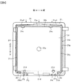
図2は、冷蔵室の内部を示す正面図である。なお、図2は、扉2a,2bおよび内部の仕切棚2cなどを取り外した状態である。   FIG. 2 is a front view showing the inside of the refrigerator compartment. FIG. 2 shows a state in which the doors 2a and 2b and the internal partition 2c are removed.

図2に示すように、断熱箱体10の外箱11は、薄い板厚の鋼板製であり、冷蔵庫本体(断熱箱体10)の筐体を構成している。また、外箱11は、鋼帯からフォーミングロールなどを使用して、左右両側の側面板11a,11bおよび天面板11cを一体に成形したものに、底面板(不図示)および背面板11d(図3参照)を、ネジ止めなどで組み付けられる。   As shown in FIG. 2, the outer box 11 of the heat insulating box 10 is made of a thin steel plate and constitutes a housing of the refrigerator body (the heat insulating box 10). The outer box 11 is formed by integrally forming the left and right side plates 11a, 11b and the top plate 11c from a steel strip using a forming roll or the like, and forms a bottom plate (not shown) and a rear plate 11d (FIG. 3) is assembled with screws or the like.

断熱箱体10の内箱12は、一枚の樹脂シートを加熱しながらエアブローを当てて延ばし、それを金型に入れ容器状に成形する真空成形法で成形されている。また、内箱12は、左側の側面壁12a、右側の側面壁12b、背面壁12c、天面壁12d(図1参照)、底面壁12e(図1参照)を一体に成形したものである。   The inner box 12 of the heat-insulating box 10 is formed by a vacuum forming method in which a single resin sheet is heated and stretched by applying air blow, and then placed in a mold and formed into a container. The inner box 12 is formed by integrally molding a left side wall 12a, a right side wall 12b, a back wall 12c, a top wall 12d (see FIG. 1), and a bottom wall 12e (see FIG. 1).

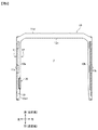
図3は、図2のA−A線断面図である。   FIG. 3 is a sectional view taken along line AA of FIG.

図3に示すように、断熱箱体10は、水平方向の断面視においてコ字状に形成されている。外箱11の側面板11a,11bは、前後方向に平行に延びている。   As shown in FIG. 3, the heat-insulating box 10 is formed in a U-shape in a horizontal cross-sectional view. The side plates 11a and 11b of the outer box 11 extend in parallel in the front-rear direction.

内箱12の側面壁12aは、背面側(後側)から正面側(前側)に向けて外箱11の側面板11a(外側面)に近づくようにゆるやかに傾斜する傾斜面12a1を有している。この傾斜面12a1は、金型からの離型性を確保するためであり、いわゆる抜きテーパと称されるものである。この傾斜面12a1(抜きテーパ)が形成されている面(側面壁12a)に操作パネル20が設けられている。なお、側面壁12bについても、側面壁12aと左右対称にして傾斜面が設けられている。   The side wall 12a of the inner box 12 has an inclined surface 12a1 that is gradually inclined from the back side (rear side) to the front side (front side) so as to approach the side plate 11a (outer side surface) of the outer box 11. I have. The inclined surface 12a1 is for securing the releasability from the mold, and is called a so-called draft taper. An operation panel 20 is provided on a surface (side wall 12a) on which the inclined surface 12a1 (pulling taper) is formed. The side wall 12b is also provided with an inclined surface symmetrically to the side wall 12a.

また、断熱箱体10の内側(壁の内部)には、真空断熱材50が設けられている。この真空断熱材50は、外箱11の側面板11a(外板)の内面に貼り付けられている。また、真空断熱材50は、その前端が操作パネル20よりも正面側(手前側、前側)に位置し、その後端が側面板11aの略後端まで延びて配置されている。   A vacuum heat insulating material 50 is provided inside the heat insulating box 10 (inside the wall). The vacuum heat insulating material 50 is attached to the inner surface of the side plate 11 a (outer plate) of the outer box 11. Further, the vacuum heat insulating material 50 has a front end located on the front side (front side, front side) of the operation panel 20 and a rear end extending to a substantially rear end of the side plate 11a.

また、真空断熱材50は、中央部に配置される芯材を成す無機繊維集合体であるグラスウール層、吸着剤などを内袋材(図示せず)で内包し、アルミ箔などのガスバリヤ性を有する外被材で真空包装されている。   In addition, the vacuum heat insulating material 50 includes a glass wool layer, an adsorbent, and the like, which are inorganic fiber aggregates forming a core material disposed in the center, in an inner bag material (not shown), and has a gas barrier property such as aluminum foil. It is vacuum-packaged with a covering material.

内袋材(図示せず)については、ポリエチレンフィルム、あるいは、ポリプロピレンフィルム、ポリエチレンテレフタレートフィルム、ポリブチレンテレフタレートフィルムなどが使用される。つまり、内袋材は、吸湿性が低く熱溶着でき、アウトガス(ガス漏洩)が少ないものを用いる。   As the inner bag material (not shown), a polyethylene film, a polypropylene film, a polyethylene terephthalate film, a polybutylene terephthalate film, or the like is used. That is, as the inner bag material, a material having low hygroscopicity, capable of being thermally welded, and having little outgas (gas leakage) is used.

吸着剤には、細孔で水分やガス分子を捕捉する物理吸着タイプの合成ゼオライトなどを用いる。なお、吸着剤は合成ゼオライトでなくとも、水分やガスを吸着するものであればよく、シリカゲルや酸化カルシウム、塩化カルシウム、酸化ストロンチウムなどの化学反応で水分やガスを吸着する化学反応型吸着剤を用いることもできる。   As the adsorbent, a physical adsorption type synthetic zeolite that captures moisture and gas molecules in pores is used. The adsorbent is not a synthetic zeolite, but may be any one that adsorbs moisture or gas.A chemically reactive adsorbent that adsorbs moisture or gas by a chemical reaction such as silica gel, calcium oxide, calcium chloride, or strontium oxide may be used. It can also be used.

外被材については、表面層として吸湿性が低いポリプロピレンフィルムを設け、防湿層としてポリエチレンテレフタレートフィルムにアルミ蒸着層を設けている。そして、ガスバリヤ層は、エチレンビニルアルコール共重合体フィルムにアルミ蒸着層を設けて、防湿層のアルミ蒸着層と向かい合わせるように貼り合せている。   As for the jacket material, a polypropylene film having low hygroscopicity is provided as a surface layer, and an aluminum vapor-deposited layer is provided on a polyethylene terephthalate film as a moisture-proof layer. The gas barrier layer is formed by providing an aluminum vapor-deposited layer on an ethylene-vinyl alcohol copolymer film and bonding it to the aluminum vapor-deposited layer of the moisture-proof layer.

本実施形態では、パネル状(平板状)の真空断熱材50を側面板11a(外板)の内壁面に貼り付けて、側面板11a(外板)と側面壁12a(内板)との間に形成される空間に硬質ウレタンフォームなどの発泡断熱材が充填される。   In the present embodiment, the panel-shaped (flat) vacuum heat insulating material 50 is attached to the inner wall surface of the side plate 11a (outer plate), and the gap between the side plate 11a (outer plate) and the side wall 12a (inner plate) is formed. Is filled with a foamed heat insulating material such as rigid urethane foam.

図4は、図3の要部拡大図である。   FIG. 4 is an enlarged view of a main part of FIG.

図4に示すように、操作パネル20は、操作ボタン22(図1参照)が設けられる表面部材21と、表面部材21の裏面側に設けられる制御基板31(回路基板)と、制御基板31を収納するとともに表面部材21を固定する基板収納部41と、を備えて構成されている。なお、操作ボタン22(図1参照)は、例えば、押圧操作式のものであり、冷蔵室2、製氷室3、上段冷凍室4、下段冷凍室5、野菜室6などの庫内の温度を変更する際に操作されるものである。   As shown in FIG. 4, the operation panel 20 includes a front member 21 provided with operation buttons 22 (see FIG. 1), a control board 31 (circuit board) provided on the back side of the front member 21, and a control board 31. A substrate accommodating portion 41 for accommodating and fixing the surface member 21. The operation button 22 (see FIG. 1) is, for example, a push-operation type, and controls the temperature in the refrigerator compartment 2, the ice making compartment 3, the upper freezing compartment 4, the lower freezing compartment 5, the vegetable compartment 6 and the like. It is operated when changing.

表面部材21は、操作ボタン22(図1参照)が設けられるパネル部21aと、このパネル部21aの裏面の外周縁部から外箱の側面板11aに向けて延びるリブ21bと、を有している。また、表面部材21は、側面壁12a(傾斜面12a1)を貫通して形成された矩形状の取付孔12fに、リブ21bが挿入されることで基板収納部41に固定される。また、パネル部21aは、取付孔12fの開口面積よりも大きい矩形状を呈し、パネル部21aの外周縁部21rの全体が取付孔12fの開口縁部12gの全体に当接するように構成されている。これにより、表面部材21によって取付孔12fの全体が閉じられ、取付孔12fが外部(庫内)から視認できないようになる。   The surface member 21 has a panel portion 21a on which operation buttons 22 (see FIG. 1) are provided, and a rib 21b extending from the outer peripheral edge of the back surface of the panel portion 21a toward the side plate 11a of the outer box. I have. The surface member 21 is fixed to the substrate housing portion 41 by inserting a rib 21b into a rectangular mounting hole 12f formed through the side wall 12a (inclined surface 12a1). The panel portion 21a has a rectangular shape larger than the opening area of the mounting hole 12f, and is configured such that the entire outer peripheral edge 21r of the panel portion 21a contacts the entire opening edge 12g of the mounting hole 12f. I have. Accordingly, the entire mounting hole 12f is closed by the surface member 21, and the mounting hole 12f cannot be visually recognized from the outside (inside of the refrigerator).

また、表面部材21は、抜きテーパを考慮して、背面側(後側)よりも正面側(前側)が側面壁12aの表面から庫内側に(庫内の幅方向の中央に向けて)突出するように(出っ張るように)構成されている。また、表面部材21(パネル部21a)の表面21a1は、真空断熱材50と略平行(または平行)に構成されている。なお、略平行とは、平行を含むとともに、表面21a1と傾斜面12a1とで成す傾きよりも平行に近い向きである。   The front surface member 21 projects from the surface of the side wall 12a toward the inside of the refrigerator (toward the center in the width direction of the refrigerator) from the surface of the side wall 12a in consideration of the draft taper. It is configured so that it protrudes (protrudes). The surface 21a1 of the surface member 21 (panel portion 21a) is configured to be substantially parallel (or parallel) to the vacuum heat insulating material 50. The term “substantially parallel” refers to a direction including parallel and closer to parallel than the inclination formed by the surface 21a1 and the inclined surface 12a1.

制御基板31は、各種の電気部品や電子部品が実装された四角板状の回路基板(適宜「基板」と省略)で構成され、表面部材21のリブ21bの内側に位置している。換言すると、制御基板31がリブ21bによって囲まれるように構成されている。操作パネル20の操作メニューが増える(多機能化する)ことによって基板が大型化している。制御基板31からの信号は、断熱箱体10の天井に設けられたメイン基板に送られ、メイン基板から庫内の温度が制御されるように構成されている。   The control board 31 is formed of a square plate-shaped circuit board (hereinafter, appropriately abbreviated as “board”) on which various electric components and electronic components are mounted, and is located inside the rib 21 b of the surface member 21. In other words, the control board 31 is configured to be surrounded by the rib 21b. As the number of operation menus on the operation panel 20 increases (multiple functions are provided), the size of the board increases. A signal from the control board 31 is sent to a main board provided on the ceiling of the heat-insulating box 10, so that the temperature in the refrigerator is controlled from the main board.

基板収納部41は、側面壁12aの裏側(断熱箱体10の内側)に配置され、制御基板31を収容する凹部42と、この凹部42の開口縁部から側面壁12aの裏面に沿って延びるつば部43と、を有して構成されている。   The board storage section 41 is arranged on the back side of the side wall 12 a (inside the heat insulating box 10), and extends along the back surface of the side wall 12 a from an opening edge of the recess 42 for housing the control board 31. And a flange 43.

凹部42は、制御基板31と平行に配置される底面部42aと、この底面部42aの周縁部から側面壁12aに向けて起立して延びる側面部42bと、を有し、取付孔12fに向けて開口するように構成されている。また、凹部42は、背面側(後側)の開口からの深さH2よりも、正面側(前側)の開口からの深さH1が浅くなるように構成されている(H2>H1)。   The concave portion 42 has a bottom surface portion 42a arranged in parallel with the control board 31 and a side surface portion 42b rising from the peripheral edge of the bottom surface portion 42a toward the side wall 12a. It is configured to open. The recess 42 is configured such that the depth H1 from the front (front) opening is smaller than the depth H2 from the rear (rear) opening (H2> H1).

また、凹部42の底面部42aは、外箱11側の裏面42cが、真空断熱材50と略平行(または平行)になるように構成されている。これにより、底面部42aの裏面42cと真空断熱材50との間の隙間Sは、背面側から正面側にかけて均一になる。なお、略平行とは、平行を含むとともに、裏面42cと傾斜面12a1とで成す傾きよりも平行に近い向きである。   Further, the bottom surface portion 42a of the concave portion 42 is configured such that the back surface 42c on the outer box 11 side is substantially parallel (or parallel) with the vacuum heat insulating material 50. Thereby, the gap S between the back surface 42c of the bottom surface portion 42a and the vacuum heat insulating material 50 becomes uniform from the back surface to the front surface. The term “substantially parallel” refers to a direction including parallel and closer to parallel than the inclination formed by the back surface 42c and the inclined surface 12a1.

また、凹部42の底面部42aは、外箱11側の裏面42cが外箱11(側面板11a)と略平行(または平行)になるように構成されている。これにより、側面板11aの裏面に真空断熱材50を取り付けた場合、底面部42aの裏面42cと真空断熱材50との間の隙間Sを、背面側から正面側にかけて均一にできる。   Further, the bottom surface portion 42a of the concave portion 42 is configured such that the back surface 42c on the outer case 11 side is substantially parallel (or parallel) to the outer case 11 (side plate 11a). Accordingly, when the vacuum heat insulating material 50 is attached to the rear surface of the side plate 11a, the gap S between the rear surface 42c of the bottom surface 42a and the vacuum heat insulating material 50 can be made uniform from the rear side to the front side.

図5は、図2のB−B線断面図である。   FIG. 5 is a sectional view taken along line BB of FIG.

図5に示すように、表面部材21のリブ21bは、制御基板31の外周縁部が当接する当接部21dが形成されている。これにより、表面部材21の裏面からの高さ位置を常に一定にできる。   As shown in FIG. 5, the rib 21b of the surface member 21 has a contact portion 21d with which the outer peripheral edge of the control board 31 contacts. Thereby, the height position from the back surface of the surface member 21 can be always kept constant.

基板収納部41の凹部42は、底面部42aから表面部材21に向けて突出する補強部41sが形成されている。補強部41sは、円筒状に形成され、底面部42aの中央から突出して形成されている。また、補強部41sの先端41s1は、側面壁12aと同一平面となる位置まで突出している。   In the concave portion 42 of the substrate housing portion 41, a reinforcing portion 41s protruding from the bottom surface portion 42a toward the surface member 21 is formed. The reinforcing portion 41s is formed in a cylindrical shape, and is formed to protrude from the center of the bottom surface portion 42a. The tip 41s1 of the reinforcing portion 41s protrudes to a position flush with the side wall 12a.

とろこで、基板収納部41に収納される収納物が小さければ、基板収納部41を小さくでき、基板収納部41の背面にウレタン(発泡断熱材)が充填されたとしても、基板収納部41にかかる発泡圧も小さい。しかし、操作メニューが増えて基板が大型化すると、ウレタンの発泡圧によって基板が変形する可能性がある。そこで、ウレタンを充填する際には、基板収納部の変形を防止するための治具を側面壁の表面側から当てる必要がある。このように基板収納部41に補強部41sを設けることで発泡圧による変形を抑えることができる。なお、補強部41sの先端41s1は、治具に突き当たる位置まで延びていればよい。   On the contrary, if the items stored in the substrate storage portion 41 are small, the substrate storage portion 41 can be made smaller. Even if urethane (foamed heat insulating material) is filled on the back surface of the substrate storage portion 41, the substrate storage portion 41 can be reduced. Foaming pressure is small. However, when the number of operation menus increases and the substrate becomes large, the substrate may be deformed by the urethane foaming pressure. Therefore, when filling the urethane, it is necessary to apply a jig for preventing deformation of the substrate storage portion from the surface side of the side wall. By providing the reinforcing portion 41s in the substrate housing portion 41 in this manner, deformation due to the foaming pressure can be suppressed. Note that the tip 41s1 of the reinforcing portion 41s only needs to extend to a position where it abuts on the jig.

また、基板収納部41に補強部41sが形成されているので、制御基板31の中央には、補強部41sを挿通可能な貫通孔31aが形成されている。これにより、補強部41sを底面部42aから側面壁12aと面一になる面まで突出させたとしても、制御基板31を基板収納部41に収納することができる。   Further, since the reinforcing portion 41 s is formed in the board storage portion 41, a through hole 31 a through which the reinforcing portion 41 s can be inserted is formed in the center of the control board 31. Thereby, even if the reinforcing portion 41s is protruded from the bottom surface portion 42a to a surface flush with the side wall 12a, the control substrate 31 can be stored in the substrate storage portion 41.

図6は、操作パネルから制御基板を残して基板収納部を取り外した状態を裏側から見た平面図である。   FIG. 6 is a plan view of a state in which the board storage section is removed from the operation panel while leaving the control board, as viewed from the back side.

図6に示すように、制御基板31は、平面視において矩形状を呈し、表面部材21の裏面に形成されたリブ21bの内側に配置されている。制御基板31の外周縁部は、リブ21bの近傍に位置している。   As shown in FIG. 6, the control board 31 has a rectangular shape in plan view, and is arranged inside a rib 21 b formed on the back surface of the front surface member 21. The outer peripheral edge of the control board 31 is located near the rib 21b.

また、制御基板31は、表面部材21の裏面に形成された爪部21c,21c,21d,21dによって制御基板31の縁部が係止されている。これにより、制御基板31が表面部材21において確実に保持される。   Further, the control board 31 has an edge portion of the control board 31 locked by claw portions 21c, 21c, 21d, 21d formed on the back surface of the front surface member 21. Thereby, the control board 31 is securely held by the surface member 21.

爪部21c,21cは、制御基板31の上部に形成され、リブ21bと一体に形成され、互いに前後方向に離間して配置されている。また、爪部21cは、リブ21bの制御基板31側の壁面に形成されている。爪部21d,21dは、表面部材21の裏面から突出して形成され、互いに前後方向に離間して配置されている。   The claw portions 21c, 21c are formed above the control board 31, are formed integrally with the rib 21b, and are arranged apart from each other in the front-rear direction. The claw portion 21c is formed on a wall surface of the rib 21b on the control board 31 side. The claw portions 21d, 21d are formed so as to protrude from the back surface of the front surface member 21, and are disposed apart from each other in the front-rear direction.

リブ21bは、制御基板31の上辺部31bに沿って形成される上部リブ21eと、制御基板31の前後両側の側辺部31c,31cに沿って形成される側部リブ21f,21gと、制御基板31の下辺部31dに沿って形成される下部リブ21h,21iと、を有し、平面視において略コ字状(略C字状)に構成されている。下部リブ21h,21iは、側部リブ21f,21gの下端から互いに対向する前後方向に向かって短く形成されている。下部リブ21h,21iの先端下面には、表面部材21の厚み方向(図6の紙面に直交する方向)に延びる突起部21h1,21i1が突出して形成されている。   The rib 21b includes upper ribs 21e formed along the upper side 31b of the control board 31, side ribs 21f, 21g formed along the front and rear side sides 31c, 31c of the control board 31, And lower ribs 21h and 21i formed along the lower side 31d of the substrate 31 and are formed in a substantially U shape (substantially C shape) in plan view. The lower ribs 21h and 21i are formed shorter from the lower ends of the side ribs 21f and 21g in the front-rear direction facing each other. Protrusions 21h1 and 21i1 extending in the thickness direction of the surface member 21 (a direction orthogonal to the plane of FIG. 6) are formed on the lower surfaces of the distal ends of the lower ribs 21h and 21i.

表面部材21の裏面には、下端部に上下方向に延びる排水溝21j,21j,21k,21kが形成されている。排水溝21j,21jは、前後方向の後側に位置している。排水溝21k,21kは、前後方向の前側に位置している。また、排水溝21j,21kは、表面部材21の裏面に、樋状(略半円状)に切り欠くことで構成されている。また、排水溝21j,21jは、下部リブ21hと上下方向において重ならない位置に形成されている。排水溝21k,21kは、下部リブ21iと上下方向において重ならない位置に形成されている。   Drainage grooves 21j, 21j, 21k, 21k extending vertically are formed at the lower end of the front surface member 21 at the lower end. The drain grooves 21j, 21j are located on the rear side in the front-rear direction. The drains 21k, 21k are located on the front side in the front-rear direction. The drain grooves 21j and 21k are formed by cutting the back surface of the surface member 21 in a gutter shape (substantially semicircular shape). Further, the drain grooves 21j, 21j are formed at positions not overlapping the lower rib 21h in the vertical direction. The drain grooves 21k, 21k are formed at positions not overlapping the lower rib 21i in the vertical direction.

また、上部リブ21eは、前後方向の中央(正面視において幅方向の中央)から前方(幅方向の一方)に向けて下るようにして傾斜する傾斜路21e1と、後方(幅方向の他方)に向けて下るようにして傾斜する傾斜路21e2と、を有している。   In addition, the upper rib 21e includes an inclined path 21e1 that is inclined downward from the center in the front-rear direction (the center in the width direction in front view) toward the front (one in the width direction), and a rearward (the other side in the width direction). And an inclined path 21e2 that is inclined downward.

図7は、操作パネルの縦断面図である。   FIG. 7 is a vertical sectional view of the operation panel.

図7に示すように、上部リブ21eは、表面部材21の裏面側から表面側に向けて下る傾斜面部21e3を有する。これにより、操作パネル20と側面壁12aとの隙間から水(結露水)などが、上部リブ21eに流れ込んだとしても、基板収納部41の底面部42a側に流れることがないので、制御基板31を保護することができる。   As shown in FIG. 7, the upper rib 21 e has an inclined surface portion 21 e 3 descending from the back surface side of the front surface member 21 toward the front surface side. Thus, even if water (condensed water) or the like flows into the upper rib 21e from the gap between the operation panel 20 and the side wall 12a, it does not flow to the bottom surface 42a side of the substrate housing portion 41, so that the control substrate 31 Can be protected.

ところで、冷蔵室2内(庫内)は低温の環境にあるので、扉2a,2bの開け閉めによって冷蔵室2に暖気が入ると、結露するおそれがあり、制御基板31を結露から守る(保護する)必要がある。そこで、リブ21eの形状を、図6および図7で説明した形状にすることで、制御基板31を結露から保護することが可能になる。すなわち、図6において破線矢印で示すように、庫内で結露が発生して、表面部材21の上部から結露水が表面部材21の裏面側に浸入した場合、結露水をまず上部リブ21eで受けることができる。このとき、上部リブ21eは傾斜路21e1,21e2を有しているので、傾斜路21e1,21e2によって結露水が前後方向(図示左右方向)に流れる。また、このとき、上部リブ21eは傾斜面部21e3(図7参照)を有しているので、結露水が制御基板31側に流れ落ちることがない。   By the way, since the inside of the refrigerator compartment 2 (the interior of the refrigerator) is in a low-temperature environment, when warm air enters the refrigerator compartment 2 by opening and closing the doors 2a and 2b, there is a possibility of dew condensation, and the control board 31 is protected from dew condensation (protection) There is a need to. Therefore, by setting the shape of the rib 21e to the shape described with reference to FIGS. 6 and 7, the control board 31 can be protected from dew condensation. That is, as shown by the dashed arrow in FIG. 6, when dew condensation occurs in the refrigerator and dew water enters the back surface of the front surface member 21 from above the front surface member 21, the dew water is first received by the upper rib 21 e. be able to. At this time, since the upper rib 21e has the slopes 21e1 and 21e2, the dew water flows in the front-rear direction (left and right directions in the drawing) by the slopes 21e1 and 21e2. At this time, since the upper rib 21e has the inclined surface portion 21e3 (see FIG. 7), the dew water does not flow down to the control board 31 side.

そして、上部リブ21eの前後方向の端部に流れた結露水は、側部リブ21f,21gの外面を表面張力によって接触しながら下方に流れ落ちる。そして、側部リブ21f,21gの下端まで流れた結露水は、下部リブ21h,21iの下面を表面張力によって接触しながら内側方に向けて流れる。そして、下部リブ21h,21iの先端まで流れた結露水は、下部リブ21h,21iの先端下面に形成された突起部21h1,21i1に当たり、下方に向けて流れ落ちる。そして、流れ落ちた結露水は、排水溝21j,21j,21k,21kを通って、表面部材21の外側に流れ出る。このように、結露水が流れ流路を形成することで、制御基板31を結露から保護することができる。   The dew water flowing to the front and rear ends of the upper rib 21e flows downward while contacting the outer surfaces of the side ribs 21f and 21g by surface tension. The dew water flowing to the lower ends of the side ribs 21f and 21g flows inward while contacting the lower surfaces of the lower ribs 21h and 21i by surface tension. The dew water flowing to the tips of the lower ribs 21h and 21i hits the projections 21h1 and 21i1 formed on the lower surfaces of the tips of the lower ribs 21h and 21i, and flows downward. Then, the condensed water that has flowed down flows out of the surface member 21 through the drain grooves 21j, 21j, 21k, 21k. Thus, the control board 31 can be protected from dew formation by forming the flow path of the dew condensation water.

次に、第1実施形態と比較例とを参照しながら発明の作用効果について説明する。図8は、操作パネルと断熱箱体との位置関係を示す概略図であり、(a)は第1実施形態、(b)は比較例である。   Next, the operation and effect of the invention will be described with reference to the first embodiment and a comparative example. 8A and 8B are schematic diagrams illustrating a positional relationship between the operation panel and the heat insulating box, wherein FIG. 8A is a first embodiment, and FIG. 8B is a comparative example.

図8(b)に示す比較例は、基板収納部141の裏面142cを傾斜面12a1に倣って形成するとともに、表面部材121の表面121aを傾斜面12a1に倣って形成した断熱箱体100の場合である。このように構成された比較例において、基板収納部141の裏面142cと真空断熱材50(表面50s)との間に形成される隙間S100は、正面側の隙間が背面側の隙間よりも狭くなり、正面側の隙間における発泡断熱材の流動性が悪化する。また、真空断熱材50が基板収納部41によって押し付けられて、真空断熱材50のリークなどの問題が発生する。   The comparative example shown in FIG. 8B is a case of the heat insulating box 100 in which the back surface 142 c of the substrate storage portion 141 is formed following the inclined surface 12 a 1 and the front surface 121 a of the surface member 121 is formed following the inclined surface 12 a 1. It is. In the comparative example thus configured, the gap S100 formed between the back surface 142c of the substrate housing portion 141 and the vacuum heat insulating material 50 (the front surface 50s) is such that the gap on the front side is smaller than the gap on the back side. In addition, the fluidity of the foamed heat insulating material in the gap on the front side deteriorates. In addition, the vacuum heat insulating material 50 is pressed by the substrate housing portion 41, and a problem such as a leak of the vacuum heat insulating material 50 occurs.

そこで、第1実施形態では、図8(a)に示すように、基板収納部41の裏面42cと真空断熱材50とを平行(略平行)にしたものである。すなわち、内箱12の側面壁12aから裏側への出っ張り(飛び出し量)について、背面側の出っ張り量(寸法)b1よりも正面側の出っ張り量(寸法)a1を少なく(小さく)したものである。これにより、基板収納部41の裏面42cと真空断熱材50(表面50s)との間の隙間Sが背面側から正面側にかけて均一になる。その結果、真空断熱材50と基板収納部41の裏面42c(操作パネル20の裏面)との寸法を短くすることができる。また、真空断熱材50の厚み寸法を大きくすることができ、冷蔵庫1Aの断熱性を高めることができる。また、第1実施形態では、基板収納部41と真空断熱材50との隙間を小さくできるので、冷蔵庫1Aの壁厚を薄くできる(側面板11aと側面壁12aとの距離を短くできる)。冷蔵庫1Aの壁厚を薄くできることで、冷蔵室2の庫内容量を増やすことができる。   Therefore, in the first embodiment, as shown in FIG. 8A, the back surface 42c of the substrate housing portion 41 and the vacuum heat insulating material 50 are parallel (substantially parallel). That is, with respect to the protrusion (projection amount) from the side wall 12a of the inner box 12 to the back side, the protrusion amount (dimension) a1 on the front side is smaller (smaller) than the protrusion amount (dimension) b1 on the back side. Thereby, the gap S between the back surface 42c of the substrate storage part 41 and the vacuum heat insulating material 50 (the front surface 50s) becomes uniform from the back side to the front side. As a result, the dimensions of the vacuum heat insulating material 50 and the back surface 42c of the substrate housing portion 41 (the back surface of the operation panel 20) can be reduced. Further, the thickness dimension of the vacuum heat insulating material 50 can be increased, and the heat insulating property of the refrigerator 1A can be improved. Further, in the first embodiment, since the gap between the substrate storage portion 41 and the vacuum heat insulating material 50 can be reduced, the wall thickness of the refrigerator 1A can be reduced (the distance between the side plate 11a and the side wall 12a can be reduced). Since the wall thickness of the refrigerator 1A can be reduced, the capacity of the refrigerator 2 can be increased.

また、第1実施形態では、図8(a)に示すように、基板収納部41の裏面42cと側面板11a(外箱11)とを平行(略平行)にしたものである。これにより、基板収納部41の裏面42cと真空断熱材50とを平行(略平行)にした場合と同様の効果を得ることができる。   In the first embodiment, as shown in FIG. 8A, the back surface 42c of the substrate housing portion 41 and the side plate 11a (outer box 11) are parallel (substantially parallel). Thereby, the same effect as when the back surface 42c of the substrate storage section 41 and the vacuum heat insulating material 50 are parallel (substantially parallel) can be obtained.

また、図8(b)の比較例において、基板収納部141の裏面142cを一点鎖線L100で示す向きにして、裏面142cと真空断熱材50とを略平行にしようとすると、制御基板31の収納スペースが確保できなくなる。   In the comparative example shown in FIG. 8B, when the back surface 142c of the substrate housing portion 141 is oriented in a direction indicated by a dashed line L100 so that the back surface 142c and the vacuum heat insulating material 50 are substantially parallel to each other, the housing of the control substrate 31 is not performed. Space cannot be secured.

そこで、第1実施形態では、図8(a)に示すように、表面部材21を、正面側が背面側よりも側面壁12a(側面)から庫内側に突出して形成したものである。すなわち、内箱12の側面壁12aから表側への出っ張りについて、背面側の出っ張り量(寸法)b2よりも正面側の出っ張り量(寸法)a2を多く(大きく)したものである。これにより、制御基板31の収納スペースを確保することができ、基板収納部41の裏面42cと真空断熱材50とを略平行(または略平行)に構成することが可能になる。その結果、真空断熱材50と基板収納部41の裏面42c(操作パネル20の裏面)との寸法を小さくすることができる。また、真空断熱材50の厚み寸法を大きくすることができ、冷蔵庫1Aの断熱性を高めることができる。また、第1実施形態では、基板収納部41と真空断熱材50との隙間を小さくできるので、冷蔵庫1Aの壁厚を小さくできる(側面板11aと側面壁12aとの距離を短くできる)。冷蔵庫1Aの壁厚を薄くできることで、冷蔵室2の庫内容量を増やすことができる。なお、基板収納部41の裏面には、真空断熱材50側へ延びるリブは設けないようにする。これにより、リブが真空断熱材50に接触することで真空断熱材50がリークするのを防止でき、またリーク防止のために真空断熱材50と基板収納部41との距離を必要以上に大きくする必要がなくなる。操作ボタン22が、タッチ式ではなく押圧式の場合は、特に有効である。   Therefore, in the first embodiment, as shown in FIG. 8A, the front surface member 21 is formed such that the front side protrudes from the side wall 12a (side surface) more toward the inside of the refrigerator than the back side. That is, with respect to the protrusion from the side wall 12a of the inner box 12 to the front side, the protrusion amount (dimension) a2 on the front side is larger (greater) than the protrusion amount (dimension) b2 on the rear side. Thereby, a storage space for the control substrate 31 can be secured, and the back surface 42c of the substrate storage portion 41 and the vacuum heat insulating material 50 can be configured substantially parallel (or substantially parallel). As a result, the dimensions of the vacuum heat insulating material 50 and the back surface 42c of the substrate housing portion 41 (the back surface of the operation panel 20) can be reduced. Further, the thickness dimension of the vacuum heat insulating material 50 can be increased, and the heat insulating property of the refrigerator 1A can be improved. Further, in the first embodiment, since the gap between the substrate housing portion 41 and the vacuum heat insulating material 50 can be reduced, the wall thickness of the refrigerator 1A can be reduced (the distance between the side plate 11a and the side wall 12a can be shortened). Since the wall thickness of the refrigerator 1A can be reduced, the capacity of the refrigerator 2 can be increased. It should be noted that a rib extending toward the vacuum heat insulating material 50 is not provided on the back surface of the substrate housing portion 41. Thereby, it is possible to prevent the vacuum heat insulating material 50 from leaking due to the ribs coming into contact with the vacuum heat insulating material 50, and to increase the distance between the vacuum heat insulating material 50 and the substrate housing portion 41 more than necessary to prevent the leak. Eliminates the need. This is particularly effective when the operation button 22 is not a touch type but a pressing type.

また、第1実施形態では、表面部材21が突出形成される側(正面側)の面の裏面に凹部21t(図6参照)が形成されている(縁部まで彫り込まれている)。これにより、凹部21tを形成することで、表面部材21の裏面縁部がつば状に形成されるので、表面部材21の強度を向上できる。また、操作パネル20の内側のスペースを有効に利用することができる。   Further, in the first embodiment, a concave portion 21t (see FIG. 6) is formed on the back surface of the surface (front side) on which the surface member 21 is formed so as to protrude (the edge portion is engraved). Thus, by forming the concave portion 21t, the rear surface edge of the surface member 21 is formed in a brim shape, so that the strength of the surface member 21 can be improved. Further, the space inside the operation panel 20 can be effectively used.

また、第1実施形態では、表面部材21の裏面には、制御基板31の上辺部31bから側辺部31cを通って下方に延びるリブ(上部リブ21eおよび側部リブ21f,21g)が突出して形成され、上部リブ21eの上面が表面部材21の裏面側から表面側に向けて下る傾斜面部21e3を有する(図7参照)。これにより、結露水が制御基板31に流れ込むのを防止することができ、制御基板31を保護して、操作パネル20の信頼性を高めることができる。   In the first embodiment, ribs (upper ribs 21e and side ribs 21f, 21g) extending downward from the upper side 31b of the control board 31 through the side 31c protrude from the rear surface of the front surface member 21. The upper rib 21e is formed and has an inclined surface portion 21e3 in which the upper surface of the upper rib 21e descends from the back surface side to the front surface side of the surface member 21 (see FIG. 7). Thereby, it is possible to prevent the dew condensation water from flowing into the control board 31, protect the control board 31, and improve the reliability of the operation panel 20.

また、第1実施形態では、上部リブ21eの上面は、正面視において幅方向中央から両側に向けて下るように傾斜する傾斜路21e1,21e2を有する。これにより、操作パネル20の上方から浸入した水(液滴)が、上部リブ21eに溜ることがなく、側部リブ21f,21gに案内することができ、制御基板31を保護することができる。   Further, in the first embodiment, the upper surface of the upper rib 21e has inclined paths 21e1 and 21e2 which are inclined from the center in the width direction toward both sides in a front view. Accordingly, water (droplets) that has entered from above the operation panel 20 can be guided to the side ribs 21f and 21g without remaining in the upper rib 21e, and the control board 31 can be protected.

また、第1実施形態では、表面部材21の裏面には、上下方向の下端に排水溝21j,21kが形成されている。これにより、万一、基板収納部41内に水が入ったとしても、排水溝21j,21kから排水することができ、操作パネルの信頼性を高めることができる。   In the first embodiment, drain grooves 21j and 21k are formed on the lower surface of the front surface member 21 at the lower end in the vertical direction. Thus, even if water enters the substrate storage section 41, the water can be drained from the drain grooves 21j and 21k, and the reliability of the operation panel can be improved.

また、第1実施形態では、リブ21bは、排水溝21j,21kと上下方向に重なる位置には形成されていない。これにより、リブ21bによって水を排水溝21j,21kに誘導することができる。   In the first embodiment, the rib 21b is not formed at a position vertically overlapping the drain grooves 21j and 21k. Thus, water can be guided to the drain grooves 21j and 21k by the rib 21b.

また、第1実施形態では、基板収納部41の底面から表面部材21の側に向けて延びる補強部41sが形成されている。これにより、発泡断熱材を充填するときに、基板収納部41の変形を防止することができる。   Further, in the first embodiment, a reinforcing portion 41 s extending from the bottom surface of the substrate housing portion 41 toward the surface member 21 is formed. Thereby, when filling the foamed heat insulating material, the deformation of the substrate housing portion 41 can be prevented.

ところで、側面壁12aの傾斜面12a1は、わずかにR形状(庫内側に凸となるように)となっている場合がある。このような場合、隙間対策として、基板収納部41も同様にR形状を持たせることが好ましい。そこで、以下に示す第2実施形態および第3実施形態では、側面壁12aにおける収納部61,81の取付箇所を平面にすることで、基板収納部61,81にR形状を持たせることが不要になる。   By the way, the inclined surface 12a1 of the side wall 12a may be slightly R-shaped (so as to be convex toward the inside of the refrigerator). In such a case, as a measure against the gap, it is preferable that the substrate storage portion 41 also has an R shape. Therefore, in the second and third embodiments described below, it is unnecessary to provide the substrate storage portions 61 and 81 with an R-shape by making the mounting portions of the storage portions 61 and 81 on the side wall 12a flat. become.

(第2実施形態)
図9は、第2実施形態の操作パネルと断熱箱体との位置関係を示す概略図である。
(2nd Embodiment)
FIG. 9 is a schematic diagram illustrating a positional relationship between the operation panel and the heat insulating box according to the second embodiment.

図9に示すように、第2実施形態の冷蔵庫1Bは、側面壁12aの傾斜面12a1に凹形状の段差部12mを形成したものである。この段差部12mは、側面壁12aの開口部から側面板11aに向けて延びる四角形状の筒体12m1と、この筒体12m1の先端から内方に向けて延びる環状部12m2と、を有している。環状部12m2は、真空断熱材50と略平行に形成されている。換言すると、環状部12m2は、側面板11aと略平行に形成されている。また、段差部12mは、側面壁12aの裏面側への出っ張り量において、背面側の出っ張り量(寸法)よりも正面側の出っ張り量(寸法)を少なく(小さく)したものである。   As shown in FIG. 9, a refrigerator 1B according to the second embodiment has a concave step 12m formed on an inclined surface 12a1 of a side wall 12a. The stepped portion 12m has a rectangular cylinder 12m1 extending from the opening of the side wall 12a toward the side plate 11a, and an annular portion 12m2 extending inward from the tip of the cylinder 12m1. I have. The annular portion 12m2 is formed substantially parallel to the vacuum heat insulating material 50. In other words, the annular portion 12m2 is formed substantially parallel to the side plate 11a. In the step portion 12m, the protrusion amount (dimension) on the front side is smaller (smaller) than the protrusion amount (dimension) on the rear surface side in the protrusion amount on the rear surface side of the side wall 12a.

表面部材51は、裏面側に向けて突出するリブ52を有し、リブ52の先端がつば部12m2の表面に当接している。   The surface member 51 has a rib 52 protruding toward the rear surface side, and the tip of the rib 52 is in contact with the surface of the flange 12m2.

基板収納部61は、制御基板31を収納する凹部62と、この凹部62の開口縁部に形成されるつば部63と、を有して構成されている。凹部62は、裏面62cが真空断熱材50と略平行に形成されている。つば部63は、環状部12m2に当接している。   The board housing section 61 includes a recess 62 for housing the control board 31 and a flange 63 formed at an opening edge of the recess 62. The recess 62 has a back surface 62 c formed substantially parallel to the vacuum heat insulating material 50. The flange portion 63 is in contact with the annular portion 12m2.

第2実施形態では、基板収納部61の裏面62cと真空断熱材50とを略平行にできるので、裏面62cと真空断熱材50との間の隙間S1を均一にできる。また、第2実施形態の表面部材51では、正面側が背面側よりも側面壁12aの傾斜面12a1から庫内側に突出して形成されている。これにより、真空断熱材50と基板収納部61の裏面62c(操作パネル20の裏面)との隙間を小さくすることができる。このように隙間を小さくできることで、真空断熱材50の厚み寸法を大きくすることができ、冷蔵庫1Aの断熱性を高めることができる。また、第2実施形態では、基板収納部61と真空断熱材50との隙間を小さくできるので、冷蔵庫1Aの壁厚を小さくできる(側面板11aと側面壁12aとの距離を短くできる)。冷蔵庫1Aの壁厚を薄くできることで、冷蔵室2の庫内容量を増やすことができる。   In the second embodiment, since the back surface 62c of the substrate housing portion 61 and the vacuum heat insulating material 50 can be substantially parallel, the gap S1 between the back surface 62c and the vacuum heat insulating material 50 can be made uniform. Further, in the surface member 51 of the second embodiment, the front side is formed so as to protrude more from the inclined surface 12a1 of the side wall 12a toward the inside of the refrigerator than the rear side. Thereby, the gap between the vacuum heat insulating material 50 and the back surface 62c of the substrate housing portion 61 (the back surface of the operation panel 20) can be reduced. Since the gap can be reduced in this way, the thickness of the vacuum heat insulating material 50 can be increased, and the heat insulation of the refrigerator 1A can be improved. Further, in the second embodiment, since the gap between the substrate housing portion 61 and the vacuum heat insulating material 50 can be reduced, the wall thickness of the refrigerator 1A can be reduced (the distance between the side plate 11a and the side wall 12a can be shortened). Since the wall thickness of the refrigerator 1A can be reduced, the capacity of the refrigerator 2 can be increased.

(第3実施形態)
図10は、第3実施形態の操作パネルと断熱箱体との位置関係を示す概略図である。
(Third embodiment)
FIG. 10 is a schematic diagram illustrating a positional relationship between an operation panel and a heat insulating box according to the third embodiment.

図10に示すように、第3実施形態の冷蔵庫1Cは、側面壁12aの傾斜面12a1に凸形状の段差部12pを形成したものである。この段差部12pは、側面壁12aの開口部から庫内に向けて延びる四角形状の筒体12p1と、この筒体12p1の先端から内方に向けて延びる環状部12p2と、を有している。環状部12p2は、真空断熱材50と略平行に形成されている。換言すると、環状部12p2は、側面板11aと略平行に形成されている。また、段差部12pは、側面壁12aの表面側への出っ張り量において、背面側の出っ張り量(寸法)よりも正面側の出っ張り量(寸法)を多く(大きく)したものである。   As shown in FIG. 10, a refrigerator 1C according to the third embodiment has a step 12p having a convex shape formed on an inclined surface 12a1 of a side wall 12a. The step portion 12p has a rectangular cylindrical body 12p1 extending from the opening of the side wall 12a toward the inside of the refrigerator, and an annular portion 12p2 extending inward from the tip of the cylindrical body 12p1. . The annular portion 12p2 is formed substantially parallel to the vacuum heat insulating material 50. In other words, the annular portion 12p2 is formed substantially parallel to the side plate 11a. In addition, the step portion 12p is such that the protrusion amount (dimension) on the front side is larger (greater) than the protrusion amount (dimension) on the back side in the protrusion amount on the surface side of the side wall 12a.

表面部材71は、裏面側に向けて突出するリブ72を有し、リブ72の先端が環状部12p2の表面に当接している。   The surface member 71 has a rib 72 protruding toward the rear surface side, and the tip of the rib 72 is in contact with the surface of the annular portion 12p2.

基板収納部81は、制御基板31を収納する凹部82と、この凹部82の開口縁部に形成されるつば部83と、を有して構成されている。凹部82は、裏面82cが真空断熱材50と略平行に形成されている。つば部83は、環状部12p2に当接している。   The board housing section 81 includes a recess 82 for housing the control board 31 and a flange 83 formed at an opening edge of the recess 82. The concave portion 82 has a back surface 82 c formed substantially parallel to the vacuum heat insulating material 50. The collar portion 83 is in contact with the annular portion 12p2.

第3実施形態では、基板収納部81の裏面82cと真空断熱材50とを略平行にできるので、裏面82cと真空断熱材50との間の隙間S2を均一にできる。また、第2実施形態では、表面部材71が、正面側が背面側よりも側面壁12aから庫内側に突出して形成されている。これにより、第2実施形態と同様の効果を得ることができる。   In the third embodiment, the back surface 82c of the substrate housing portion 81 and the vacuum heat insulating material 50 can be made substantially parallel, so that the gap S2 between the back surface 82c and the vacuum heat insulating material 50 can be made uniform. Further, in the second embodiment, the surface member 71 is formed such that the front side protrudes from the side wall 12a to the inner side of the storage than the back side. Thereby, the same effect as in the second embodiment can be obtained.

なお、第2実施形態では、側面壁12aを凹形状にし、第3実施形態では、側面壁12aを凸形状にした場合を例に挙げて説明したが、凹形状や凸形状にせずに単に取付箇所を平面にする構成であってもよい。   In the second embodiment, the side wall 12a has a concave shape, and in the third embodiment, the case where the side wall 12a has a convex shape has been described as an example. The configuration may be such that the portion is a plane.

ところで、基板収納部41(以下、ケースとする)と外板(側面板11a)との間の隙間を小さくすると、ケースと真空断熱材50との間の隙間において、その隙間の周囲ではウレタン(発泡断熱材)が入るものの、中央付近にはウレタンが入らない状態も想定される。また、操作パネル20が多機能化することで制御基板31が大型化して、制御基板31を収納するケースも大型化し、ウレタン充填時の発泡圧の影響を受け易くなる。発泡圧力とウレタン密度の関係は、図11(a)に示すようになる。すなわち、隙間を小さくするとウレタン密度が上昇するので、ウレタン密度の上昇によって発泡圧力が高くなる。これによって、ケースなどの部品の損傷や変形などの不具合を生じる。そこで、このような不具合を回避するため、ウレタン密度(ρ)は、以下の関係式1を満足し、この式を満たす密度のウレタンを使用した冷蔵庫とする。   By the way, when the gap between the substrate storage portion 41 (hereinafter, referred to as a case) and the outer plate (side plate 11a) is reduced, urethane (urethane) is formed around the gap between the case and the vacuum heat insulating material 50. A state in which urethane does not enter near the center although foam insulating material) enters is also assumed. In addition, the multi-functional operation panel 20 increases the size of the control board 31 and the size of the case for accommodating the control board 31, making the control panel 31 more susceptible to the foaming pressure during urethane filling. The relationship between the foaming pressure and the urethane density is as shown in FIG. That is, when the gap is reduced, the urethane density increases, so that the foaming pressure increases due to the increase in the urethane density. This causes problems such as damage and deformation of parts such as the case. Then, in order to avoid such a problem, the urethane density (ρ) satisfies the following relational expression 1, and a refrigerator using urethane having a density satisfying this expression is used.

Ln(ρ)≦1066.7×K/A−17.48・・・・・・・・・・・・(式1)
ρ:ウレタン密度(kg/mm
K:ケース剛性(N/mm)
A:ケース裏面に入り込んだウレタンとケースとの設置面積(mm
なお、ケース剛性Kは、図11(b)に示すように、ケース外周およびケース内部の突起部の全てを支持した状態で、これに荷重Fを与え、(荷重F:N)/(変形量R:mm)によって求まる数値である。
Ln (ρ) ≦ 1066.7 × K / A−17.48 (1)
ρ: urethane density (kg / mm 3 )
K: Case rigidity (N / mm)
A: Installation area (mm 2 ) between the urethane and the case that entered the back of the case
As shown in FIG. 11B, the case rigidity K is such that a load F is applied to the case in a state in which all of the outer periphery of the case and the projections inside the case are supported, and (load F: N) / (deformation amount). R: mm).

本実施形態のような構造では、ケースによって断熱部が薄くなり、ウレタンの厚みが減少し、ウレタン密度が上昇する傾向にある。そこで、本実施形態では、ウレタン密度が45kg/m以上となっている場合を想定している。 In the structure as in the present embodiment, the heat insulating portion becomes thinner depending on the case, the thickness of urethane decreases, and the urethane density tends to increase. Therefore, in the present embodiment, it is assumed that the urethane density is 45 kg / m 3 or more.

次に、式1の根拠について説明すると、密度(ρ:kg/mm)と発泡圧(P:MPa)の関係より発泡による変形量は、下記(式2)の左辺で表すことができる。そして、ウレタン密度と発泡圧の関係は、発明者らが行った実験結果よれば、図11(a)のような傾向を示す。また、ウレタン発泡圧からケースなどの部品の損傷を防ぐ為には(式2)の関係を満足する必要がある。 Next, the basis of Equation 1 will be described. Based on the relationship between density (ρ: kg / mm 3 ) and foaming pressure (P: MPa), the amount of deformation due to foaming can be expressed by the left side of (Formula 2) below. According to the results of experiments conducted by the inventors, the relationship between urethane density and foaming pressure shows a tendency as shown in FIG. Further, in order to prevent damage to parts such as a case from urethane foaming pressure, it is necessary to satisfy the relationship of (Equation 2).

[発泡圧]×[面積]/[ケース剛性]≦[許容値]・・・・・・・・・(式2)
そして、ケースと真空断熱材との隙間が1.0mm程度と仮定すると、ウレタン密度は一般的に500×10^9kg/mm程度となる。この場合の発泡圧(MPa)を、図11(a)で得られる関係式から算出し、CAE解析によりケース剛性Kを求め、(式2)の右辺に相当する許容値を定めた。なお、今後の操作パネルの多機能化により、大きさが2倍となることを想定し、また材料変更などで、ケース剛性Kが1/4となることを見込み、許容値は8倍程度必要と考える。よって安全率を8としている。
以上で説明した、図11(a)で得られる関係式、(式2)、安全率を考慮した許容値、により、(式1)が導かれ、ケースの損傷や変形に対するウレタン密度の条件式となる。
[Blowing pressure] × [Area] / [Case rigidity] ≦ [Permissible value] (2)
Assuming that the gap between the case and the vacuum heat insulating material is about 1.0 mm, the urethane density is generally about 500 × 10 9 kg / mm 3 . The foaming pressure (MPa) in this case was calculated from the relational expression obtained in FIG. 11A, the case rigidity K was obtained by CAE analysis, and an allowable value corresponding to the right side of (Equation 2) was determined. In addition, it is assumed that the size will be doubled due to the future multi-functional operation panel, and it is expected that the case rigidity K will be reduced to 1/4 due to material change, etc., and the allowable value is required about 8 times. Think. Therefore, the safety factor is set to 8.
(Equation 1) is derived from the relational expression obtained in FIG. 11A described above, (Equation 2), and the allowable value in consideration of the safety factor, and the conditional expression of the urethane density with respect to the damage and deformation of the case. Becomes

断熱箱体10の壁厚を薄くした場合、ケースと真空断熱材との隙間が必然的に狭くなる。例えば、隙間を10mm未満にすると、ウレタン密度が高いので、発泡圧が高くなり、変形し易くなる。そこで、基板(制御基板31)を収納するケース(基板収納部41)と、外板(または真空断熱材50)との間に、少なくとも中央付近にウレタン(発泡断熱材)が介在しない冷蔵庫を提供することで、発泡圧による変形を抑制することができ、余裕を持たせるために必要だったスペースを節約できる。   When the wall thickness of the heat insulating box 10 is reduced, the gap between the case and the vacuum heat insulating material is necessarily narrowed. For example, when the gap is less than 10 mm, the urethane density is high, so that the foaming pressure is increased and the gap is easily deformed. Therefore, there is provided a refrigerator in which urethane (foam insulating material) is not interposed at least near the center between a case (substrate storing portion 41) for storing a substrate (control substrate 31) and an outer plate (or vacuum heat insulating material 50). By doing so, the deformation due to the foaming pressure can be suppressed, and the space required for providing a margin can be saved.

また、図12に示すように、ケース(基板収納部41)と真空断熱材50との間に、介在部材90を設けてもよい。介在部材90は、発泡断熱材の浸入を抑えるまたは防ぐ部材であり、軟質ウレタンなどのスポンジ状のもの、あるいは発泡スチロールなどを適用できる。また、ケースと真空断熱材50との間の距離を6mm以下に狭く設定すれば、ケースと真空断熱材50との間に発泡断熱材が侵入し難くなる。   Further, as shown in FIG. 12, an intervening member 90 may be provided between the case (substrate storage section 41) and the vacuum heat insulating material 50. The intervening member 90 is a member that suppresses or prevents the penetration of the foamed heat insulating material, and a sponge-like material such as soft urethane or a polystyrene foam can be used. If the distance between the case and the vacuum heat insulating material 50 is set to a small value of 6 mm or less, it becomes difficult for the foam heat insulating material to enter between the case and the vacuum heat insulating material 50.

また、介在部材90を設けることで、ケースと真空断熱材50とが直接接触しないので、真空断熱材50のリークを防止できる。また、介在部材90は、ケースと真空断熱材50との間の隙間を塞ぐ圧縮性部材(もともとの隙間の寸法よりも大きいものをつぶして介在させたもの)であってもよい。なお、圧縮性部材としては、発泡スチロール、ポリエチレンフォームを適用できる。また、介在部材90は、発泡断熱材が浸みこまないものが好ましい。   In addition, since the case and the vacuum heat insulating material 50 do not come into direct contact with each other by providing the intervening member 90, leakage of the vacuum heat insulating material 50 can be prevented. In addition, the intervening member 90 may be a compressible member that closes the gap between the case and the vacuum heat insulating material 50 (one that is crushed and interposed by a member larger than the size of the original gap). Note that, as the compressible member, styrene foam and polyethylene foam can be applied. Further, it is preferable that the interposed member 90 does not penetrate the foamed heat insulating material.

なお、本発明は、前記した実施形態に限定されるものではなく、様々な変形例が含まれる。例えば、本実施形態では、操作パネル20を庫内の側面壁12aの傾斜面12a1に設けた場合について説明したが、庫内灯が設けられる天面壁12dに適用してもよい。あるいは、冷蔵庫の上面のメイン基板が搭載されている場所に適用してもよい。あるいは、IOT(Internet of Things)の基板を搭載する場所に適用してもよい。   Note that the present invention is not limited to the above-described embodiment, and includes various modifications. For example, in the present embodiment, the case where the operation panel 20 is provided on the inclined surface 12a1 of the side wall 12a inside the refrigerator has been described, but the operation panel 20 may be applied to the top wall 12d provided with the interior lamp. Alternatively, the present invention may be applied to a place on the upper surface of the refrigerator where the main board is mounted. Alternatively, the present invention may be applied to a place where an IOT (Internet of Things) substrate is mounted.

1A,1B,1C 冷蔵庫
10 断熱箱体
11 外箱
12 内箱
12a 側面壁(側面)
12a1 傾斜面
12m,12p 段差部
20 操作パネル(ユニット部材)
21 表面部材
21b リブ
21e 上部リブ
21e1,21e2 傾斜路
21e3 傾斜面部
21f,21g 側部リブ
21h,21i 下部リブ
21j,21k 排水溝
21t 凹部
31 制御基板(回路基板)
31b 上辺部
31c 側辺部
31d 下辺部
41 基板収納部
41s 補強部
41s1 先端
42c 裏面(外箱と対向する側の面)
50 真空断熱材
1A, 1B, 1C Refrigerator 10 Insulated box 11 Outer box 12 Inner box 12a Side wall (side)
12a1 Inclined surface 12m, 12p Step 20 Operation panel (unit member)
Reference Signs List 21 surface member 21b rib 21e upper rib 21e1, 21e2 ramp 21e3 slope 21f, 21g side rib 21h, 21i lower rib 21j, 21k drain groove 21t recess 31 control board (circuit board)
31b Upper side part 31c Side side part 31d Lower side part 41 Substrate storage part 41s Reinforcement part 41s1 Tip 42c Back side (surface on the side facing the outer box)
50 Vacuum insulation

Claims (7)

表面部材、前記表面部材の裏面側に設けられる回路基板、および前記回路基板の裏面側に設けられる基板収納部を有し、前記回路基板を収納するユニット部材と、
内箱と外箱との間に断熱材として少なくとも真空断熱材を設けるとともに前記ユニット部材が前記内箱の左右少なくとも一方の側面に配置される断熱箱体と、を備え、
前記真空断熱材または前記外箱に対向する前記基板収納部の底面と前記真空断熱材または前記外箱との間の隙間において、少なくとも中央付近には発泡断熱材が介在せず、
前記ユニット部材が配置された前記側面は、背面側から正面側に向けて前記外箱の側面板に近づくように傾斜する傾斜面を有し、
前記側面から前記外箱の在る側に向かって前記ユニット部材が出っ張った寸法は、背面側よりも正面側が小さいことを特徴とする冷蔵庫。
A surface member, a circuit board provided on the back surface side of the surface member, and a unit member for housing the circuit board, having a board storage portion provided on the back surface side of the circuit board ;
A heat insulation box provided with at least a vacuum heat insulation material as a heat insulation material between the inner box and the outer box, and the unit member is disposed on at least one of the left and right sides of the inner box,
In the gap between the vacuum heat insulating material or the bottom surface of the substrate storage portion facing the outer box and the vacuum heat insulating material or the outer box, at least near the center, no foamed heat insulating material is interposed ,
The side surface on which the unit member is disposed has an inclined surface that is inclined from the rear side toward the front side so as to approach the side plate of the outer box,
A refrigerator in which a dimension of the unit member protruding from the side surface toward a side where the outer box is present is smaller on a front side than on a rear side .
表面部材、前記表面部材の裏面側に設けられる回路基板、および前記回路基板の裏面側に設けられる基板収納部を有し、前記回路基板を収納するユニット部材と、
内箱と外箱との間に発泡断熱材および真空断熱材を設けるとともに前記ユニット部材が前記内箱の左右少なくとも一方の側面に配置される断熱箱体と、を備え、
前記真空断熱材または前記外箱に対向する前記基板収納部の底面と前記真空断熱材または前記外箱との間の隙間において、前記発泡断熱材の密度をρ(kg/mm3)、前記基板収納部の剛性をK(N/mm)、前記発泡断熱材と前記基板収納部との接触面積をA(mm2)としたとき、
Ln(ρ)≦1066.7×K/A−17.48
の関係式を満たし、
前記ユニット部材が配置された前記側面は、背面側から正面側に向けて前記外箱の側面板に近づくように傾斜する傾斜面を有し、
前記側面から前記外箱の在る側に向かって前記ユニット部材が出っ張った寸法は、背面側よりも正面側が小さいことを特徴とする冷蔵庫。
A surface member, a circuit board provided on the back surface side of the surface member, and a unit member for housing the circuit board, having a board storage portion provided on the back surface side of the circuit board ;
Provided with a foam heat insulating material and a vacuum heat insulating material between the inner box and the outer box, and a heat insulating box body in which the unit member is disposed on at least one of the left and right sides of the inner box,
In a gap between the vacuum heat insulating material or the bottom surface of the substrate storage unit facing the outer box and the vacuum heat insulating material or the outer box, the density of the foamed heat insulating material is ρ (kg / mm3). When the rigidity of the section is K (N / mm) and the contact area between the foamed heat insulating material and the substrate storage section is A (mm2),
Ln (ρ) ≦ 1066.7 × K / A-17.48
Meet the relationship,
The side surface on which the unit member is disposed has an inclined surface that is inclined from the rear side toward the front side so as to approach the side plate of the outer box,
A refrigerator in which a dimension of the unit member protruding from the side surface toward a side where the outer box is present is smaller on a front side than on a rear side .
表面部材、前記表面部材の裏面側に設けられる回路基板、および前記回路基板の裏面側に設けられる基板収納部を有し、前記回路基板を収納するユニット部材と、
内箱と外箱との間に発泡断熱材および真空断熱材を設けるとともに前記ユニット部材が前記内箱の左右少なくとも一方の側面に配置される断熱箱体と、を備え、
前記真空断熱材または前記外箱に対向する前記基板収納部の底面と前記真空断熱材または前記外箱との間に、前記発泡断熱材の前記基板収納部の底面の少なくとも中央付近の裏側への浸入を抑制する介在部材を設け
前記ユニット部材が配置された前記側面は、背面側から正面側に向けて前記外箱の側面板に近づくように傾斜する傾斜面を有し、
前記側面から前記外箱の在る側に向かって前記ユニット部材が出っ張った寸法は、背面側よりも正面側が小さいことを特徴とする冷蔵庫。
A surface member, a circuit board provided on the back surface side of the surface member, and a unit member for housing the circuit board, having a board storage portion provided on the back surface side of the circuit board ;
Provided with a foam heat insulating material and a vacuum heat insulating material between the inner box and the outer box, and a heat insulating box body in which the unit member is disposed on at least one of the left and right sides of the inner box,
Between the bottom surface of the substrate housing portion facing the vacuum heat insulating material or the outer box and the vacuum heat insulating material or the outer box , at least the center of the bottom surface of the substrate housing portion of the foamed heat insulating material to the back side. An intervening member that suppresses intrusion is provided ,
The side surface on which the unit member is disposed has an inclined surface that is inclined from the rear side toward the front side so as to approach the side plate of the outer box,
A refrigerator in which a dimension of the unit member protruding from the side surface toward a side where the outer box is present is smaller on a front side than on a rear side .
表面部材、前記表面部材の裏面側に設けられる回路基板、および前記回路基板の裏面側に設けられる基板収納部を有し、前記回路基板を収納するユニット部材と、  A surface member, a circuit board provided on the back surface side of the surface member, and a unit member for housing the circuit board, having a board storage portion provided on the back surface side of the circuit board;
内箱と外箱との間に断熱材として少なくとも真空断熱材を設けるとともに前記ユニット部材が前記内箱の左右少なくとも一方の側面に配置される断熱箱体と、を備え、  A heat insulation box provided with at least a vacuum heat insulation material as a heat insulation material between the inner box and the outer box, and the unit member is disposed on at least one of the left and right sides of the inner box,
前記真空断熱材または前記外箱に対向する前記ユニット部材が配置された前記側面は、背面側から正面側に向けて前記外箱の側面板に近づくように傾斜する傾斜面を有し、  The side surface on which the unit member facing the vacuum heat insulating material or the outer box is disposed has an inclined surface that is inclined from the rear side toward the front side so as to approach the side plate of the outer box,
前記側面から前記外箱の在る側に向かって前記ユニット部材が出っ張った寸法は、背面側よりも正面側が小さいことを特徴とする冷蔵庫。  A refrigerator in which a dimension of the unit member protruding from the side surface toward a side where the outer box is present is smaller on a front side than on a rear side.
前記基板収納部の底面は、前記内箱の左右少なくとも一方の側面壁に向けて突出した補強部と、  A bottom surface of the substrate storage portion, a reinforcing portion protruding toward at least one of the left and right side walls of the inner box,
前記制御基板に配され、該補強部が挿通した貫通孔と、を有する請求項1乃至4何れか一項に記載の冷蔵庫。  The refrigerator according to any one of claims 1 to 4, further comprising a through-hole disposed on the control board and through which the reinforcing portion is inserted.
表面部材、前記表面部材の裏面側に設けられる回路基板、および前記回路基板の裏面側に設けられる基板収納部を有し、前記回路基板を収納するユニット部材と、  A surface member, a circuit board provided on the back surface side of the surface member, and a unit member for housing the circuit board, having a board storage portion provided on the back surface side of the circuit board;
内箱と外箱との間に断熱材として少なくとも真空断熱材を設けるとともに前記ユニット部材が前記内箱の左右少なくとも一方の側面に配置される断熱箱体と、を備え、  A heat insulation box provided with at least a vacuum heat insulation material as a heat insulation material between the inner box and the outer box, and the unit member is disposed on at least one of the left and right sides of the inner box,
前記真空断熱材または前記外箱に対向する前記基板収納部の底面の少なくとも中央付近の裏側には発泡断熱材が発泡充填されず、  At least the back side near the center of the bottom surface of the substrate housing portion facing the vacuum heat insulating material or the outer box is not filled with foamed heat insulating material,
前記ユニット部材が配置された前記側面は、背面側から正面側に向けて前記外箱の側面板に近づくように傾斜する傾斜面を有し、  The side surface on which the unit member is disposed has an inclined surface that is inclined from the rear side toward the front side so as to approach the side plate of the outer box,
前記側面から前記外箱の在る側に向かって前記ユニット部材が出っ張った寸法は、背面側よりも正面側が小さいことを特徴とする冷蔵庫。  A refrigerator in which a dimension of the unit member protruding from the side surface toward a side where the outer box is present is smaller on a front side than on a rear side.
前記底面の裏側の少なくとも中央付近から前記外箱側に在る空隙の幅寸法が6mm以下である請求項1乃至6何れか一項に記載の冷蔵庫。  The refrigerator according to any one of claims 1 to 6, wherein a width dimension of a gap existing at least from near the center on the back side of the bottom surface to the outer box side is 6 mm or less.
JP2017149597A 2017-08-02 2017-08-02 refrigerator Active JP6670803B2 (en)

Priority Applications (5)

Application Number Priority Date Filing Date Title
JP2017149597A JP6670803B2 (en) 2017-08-02 2017-08-02 refrigerator
CN201810182854.4A CN109387010B (en) 2017-08-02 2018-03-06 Refrigerator with a door
CN202010975075.7A CN112013604B (en) 2017-08-02 2018-03-06 Refrigerator with a door
TW107107612A TWI689693B (en) 2017-08-02 2018-03-07 refrigerator
TW108140919A TWI734253B (en) 2017-08-02 2018-03-07 refrigerator

Applications Claiming Priority (1)

Application Number Priority Date Filing Date Title
JP2017149597A JP6670803B2 (en) 2017-08-02 2017-08-02 refrigerator

Related Child Applications (1)

Application Number Title Priority Date Filing Date
JP2020032576A Division JP6833087B2 (en) 2020-02-28 2020-02-28 refrigerator

Publications (3)

Publication Number Publication Date
JP2019027723A JP2019027723A (en) 2019-02-21
JP2019027723A5 JP2019027723A5 (en) 2019-10-03
JP6670803B2 true JP6670803B2 (en) 2020-03-25

Family

ID=65476115

Family Applications (1)

Application Number Title Priority Date Filing Date
JP2017149597A Active JP6670803B2 (en) 2017-08-02 2017-08-02 refrigerator

Country Status (1)

Country Link
JP (1) JP6670803B2 (en)

Families Citing this family (1)

* Cited by examiner, † Cited by third party
Publication number Priority date Publication date Assignee Title
EP4177554B1 (en) * 2021-11-05 2024-06-26 Arçelik Anonim Sirketi A cooling device

Also Published As

Publication number Publication date
JP2019027723A (en) 2019-02-21

Similar Documents

Publication Publication Date Title
KR102366410B1 (en) Refrigerator and vacuum insulation module thereof
US9696083B2 (en) Refrigerator
JP5903567B2 (en) refrigerator
US8079231B2 (en) Housing for a refrigerator
JP6746243B2 (en) refrigerator
JP2005164193A (en) Refrigerator
JP4196851B2 (en) refrigerator
JP5868152B2 (en) refrigerator
JP6670803B2 (en) refrigerator
JP6797091B2 (en) Refrigerator and this manufacturing method
TWI734253B (en) refrigerator
JP6833087B2 (en) refrigerator
JP6815948B2 (en) refrigerator
JP2009042947A (en) Vending machine
JP6392144B2 (en) refrigerator
JP6735075B2 (en) refrigerator
WO2023152996A1 (en) Insulated door and storage
JP3823993B2 (en) refrigerator
JP2005024204A (en) Refrigerator
JP2009257715A (en) Refrigerator and vacuum heat insulating material
JP7038274B2 (en) refrigerator
JP2024086242A (en) Refrigerator and manufacturing method for refrigerator
JP2024061274A (en) Refrigerator door and refrigerator
JP2022136422A (en) Heat insulating box body and refrigerator
JP2013185732A (en) Refrigerator

Legal Events

Date Code Title Description
A521 Written amendment

Free format text: JAPANESE INTERMEDIATE CODE: A523

Effective date: 20170804

A521 Written amendment

Free format text: JAPANESE INTERMEDIATE CODE: A523

Effective date: 20190823

A621 Written request for application examination

Free format text: JAPANESE INTERMEDIATE CODE: A621

Effective date: 20190823

A521 Written amendment

Free format text: JAPANESE INTERMEDIATE CODE: A523

Effective date: 20190823

A871 Explanation of circumstances concerning accelerated examination

Free format text: JAPANESE INTERMEDIATE CODE: A871

Effective date: 20191021

A975 Report on accelerated examination

Free format text: JAPANESE INTERMEDIATE CODE: A971005

Effective date: 20191030

A131 Notification of reasons for refusal

Free format text: JAPANESE INTERMEDIATE CODE: A131

Effective date: 20191112

A521 Written amendment

Free format text: JAPANESE INTERMEDIATE CODE: A523

Effective date: 20191225

A521 Written amendment

Free format text: JAPANESE INTERMEDIATE CODE: A523

Effective date: 20191226

TRDD Decision of grant or rejection written
A01 Written decision to grant a patent or to grant a registration (utility model)

Free format text: JAPANESE INTERMEDIATE CODE: A01

Effective date: 20200204

A61 First payment of annual fees (during grant procedure)

Free format text: JAPANESE INTERMEDIATE CODE: A61

Effective date: 20200302

R150 Certificate of patent or registration of utility model

Ref document number: 6670803

Country of ref document: JP

Free format text: JAPANESE INTERMEDIATE CODE: R150