JP6669931B2 - Fast charging method and system, terminal and charger - Google Patents
Fast charging method and system, terminal and charger Download PDFInfo
- Publication number
- JP6669931B2 JP6669931B2 JP2019500725A JP2019500725A JP6669931B2 JP 6669931 B2 JP6669931 B2 JP 6669931B2 JP 2019500725 A JP2019500725 A JP 2019500725A JP 2019500725 A JP2019500725 A JP 2019500725A JP 6669931 B2 JP6669931 B2 JP 6669931B2
- Authority
- JP
- Japan
- Prior art keywords
- terminal
- voltage
- charger
- battery
- value
- Prior art date
- Legal status (The legal status is an assumption and is not a legal conclusion. Google has not performed a legal analysis and makes no representation as to the accuracy of the status listed.)
- Active
Links
- 238000007600 charging Methods 0.000 title claims description 126
- 238000000034 method Methods 0.000 title claims description 46
- 238000006243 chemical reaction Methods 0.000 claims description 64
- 238000001514 detection method Methods 0.000 claims description 12
- 238000012545 processing Methods 0.000 claims description 4
- 239000003990 capacitor Substances 0.000 description 8
- 238000010586 diagram Methods 0.000 description 6
- 230000006870 function Effects 0.000 description 6
- 238000004891 communication Methods 0.000 description 5
- 230000000295 complement effect Effects 0.000 description 2
- 230000008878 coupling Effects 0.000 description 2
- 238000010168 coupling process Methods 0.000 description 2
- 238000005859 coupling reaction Methods 0.000 description 2
- 238000007599 discharging Methods 0.000 description 2
- 238000005516 engineering process Methods 0.000 description 2
- HBBGRARXTFLTSG-UHFFFAOYSA-N Lithium ion Chemical compound [Li+] HBBGRARXTFLTSG-UHFFFAOYSA-N 0.000 description 1
- 238000010280 constant potential charging Methods 0.000 description 1
- 230000002354 daily effect Effects 0.000 description 1
- 230000001419 dependent effect Effects 0.000 description 1
- 238000013461 design Methods 0.000 description 1
- 238000011161 development Methods 0.000 description 1
- 230000005611 electricity Effects 0.000 description 1
- 230000003203 everyday effect Effects 0.000 description 1
- 238000001914 filtration Methods 0.000 description 1
- 229910001416 lithium ion Inorganic materials 0.000 description 1
- 230000003287 optical effect Effects 0.000 description 1
- 238000011895 specific detection Methods 0.000 description 1
Images


Classifications
-
- H—ELECTRICITY
- H02—GENERATION; CONVERSION OR DISTRIBUTION OF ELECTRIC POWER
- H02J—CIRCUIT ARRANGEMENTS OR SYSTEMS FOR SUPPLYING OR DISTRIBUTING ELECTRIC POWER; SYSTEMS FOR STORING ELECTRIC ENERGY
- H02J7/00—Circuit arrangements for charging or depolarising batteries or for supplying loads from batteries
- H02J7/007—Regulation of charging or discharging current or voltage
- H02J7/00712—Regulation of charging or discharging current or voltage the cycle being controlled or terminated in response to electric parameters
-
- H—ELECTRICITY
- H02—GENERATION; CONVERSION OR DISTRIBUTION OF ELECTRIC POWER
- H02J—CIRCUIT ARRANGEMENTS OR SYSTEMS FOR SUPPLYING OR DISTRIBUTING ELECTRIC POWER; SYSTEMS FOR STORING ELECTRIC ENERGY
- H02J7/00—Circuit arrangements for charging or depolarising batteries or for supplying loads from batteries
-
- G—PHYSICS
- G01—MEASURING; TESTING
- G01R—MEASURING ELECTRIC VARIABLES; MEASURING MAGNETIC VARIABLES
- G01R31/00—Arrangements for testing electric properties; Arrangements for locating electric faults; Arrangements for electrical testing characterised by what is being tested not provided for elsewhere
- G01R31/36—Arrangements for testing, measuring or monitoring the electrical condition of accumulators or electric batteries, e.g. capacity or state of charge [SoC]
- G01R31/3644—Constructional arrangements
- G01R31/3648—Constructional arrangements comprising digital calculation means, e.g. for performing an algorithm
-
- H—ELECTRICITY
- H01—ELECTRIC ELEMENTS
- H01M—PROCESSES OR MEANS, e.g. BATTERIES, FOR THE DIRECT CONVERSION OF CHEMICAL ENERGY INTO ELECTRICAL ENERGY
- H01M10/00—Secondary cells; Manufacture thereof
- H01M10/42—Methods or arrangements for servicing or maintenance of secondary cells or secondary half-cells
- H01M10/44—Methods for charging or discharging
-
- H—ELECTRICITY
- H02—GENERATION; CONVERSION OR DISTRIBUTION OF ELECTRIC POWER
- H02J—CIRCUIT ARRANGEMENTS OR SYSTEMS FOR SUPPLYING OR DISTRIBUTING ELECTRIC POWER; SYSTEMS FOR STORING ELECTRIC ENERGY
- H02J7/00—Circuit arrangements for charging or depolarising batteries or for supplying loads from batteries
- H02J7/0029—Circuit arrangements for charging or depolarising batteries or for supplying loads from batteries with safety or protection devices or circuits
- H02J7/00302—Overcharge protection
-
- H—ELECTRICITY
- H02—GENERATION; CONVERSION OR DISTRIBUTION OF ELECTRIC POWER
- H02J—CIRCUIT ARRANGEMENTS OR SYSTEMS FOR SUPPLYING OR DISTRIBUTING ELECTRIC POWER; SYSTEMS FOR STORING ELECTRIC ENERGY
- H02J7/00—Circuit arrangements for charging or depolarising batteries or for supplying loads from batteries
- H02J7/0029—Circuit arrangements for charging or depolarising batteries or for supplying loads from batteries with safety or protection devices or circuits
- H02J7/0031—Circuit arrangements for charging or depolarising batteries or for supplying loads from batteries with safety or protection devices or circuits using battery or load disconnect circuits
-
- H—ELECTRICITY
- H02—GENERATION; CONVERSION OR DISTRIBUTION OF ELECTRIC POWER
- H02J—CIRCUIT ARRANGEMENTS OR SYSTEMS FOR SUPPLYING OR DISTRIBUTING ELECTRIC POWER; SYSTEMS FOR STORING ELECTRIC ENERGY
- H02J7/00—Circuit arrangements for charging or depolarising batteries or for supplying loads from batteries
- H02J7/0042—Circuit arrangements for charging or depolarising batteries or for supplying loads from batteries characterised by the mechanical construction
-
- H—ELECTRICITY
- H02—GENERATION; CONVERSION OR DISTRIBUTION OF ELECTRIC POWER
- H02J—CIRCUIT ARRANGEMENTS OR SYSTEMS FOR SUPPLYING OR DISTRIBUTING ELECTRIC POWER; SYSTEMS FOR STORING ELECTRIC ENERGY
- H02J7/00—Circuit arrangements for charging or depolarising batteries or for supplying loads from batteries
- H02J7/0047—Circuit arrangements for charging or depolarising batteries or for supplying loads from batteries with monitoring or indicating devices or circuits
-
- H—ELECTRICITY
- H02—GENERATION; CONVERSION OR DISTRIBUTION OF ELECTRIC POWER
- H02J—CIRCUIT ARRANGEMENTS OR SYSTEMS FOR SUPPLYING OR DISTRIBUTING ELECTRIC POWER; SYSTEMS FOR STORING ELECTRIC ENERGY
- H02J7/00—Circuit arrangements for charging or depolarising batteries or for supplying loads from batteries
- H02J7/007—Regulation of charging or discharging current or voltage
- H02J7/00712—Regulation of charging or discharging current or voltage the cycle being controlled or terminated in response to electric parameters
- H02J7/007182—Regulation of charging or discharging current or voltage the cycle being controlled or terminated in response to electric parameters in response to battery voltage
- H02J7/007184—Regulation of charging or discharging current or voltage the cycle being controlled or terminated in response to electric parameters in response to battery voltage in response to battery voltage gradient
-
- H—ELECTRICITY
- H01—ELECTRIC ELEMENTS
- H01M—PROCESSES OR MEANS, e.g. BATTERIES, FOR THE DIRECT CONVERSION OF CHEMICAL ENERGY INTO ELECTRICAL ENERGY
- H01M10/00—Secondary cells; Manufacture thereof
- H01M10/42—Methods or arrangements for servicing or maintenance of secondary cells or secondary half-cells
- H01M10/425—Structural combination with electronic components, e.g. electronic circuits integrated to the outside of the casing
- H01M10/4257—Smart batteries, e.g. electronic circuits inside the housing of the cells or batteries
-
- H—ELECTRICITY
- H02—GENERATION; CONVERSION OR DISTRIBUTION OF ELECTRIC POWER
- H02J—CIRCUIT ARRANGEMENTS OR SYSTEMS FOR SUPPLYING OR DISTRIBUTING ELECTRIC POWER; SYSTEMS FOR STORING ELECTRIC ENERGY
- H02J2207/00—Indexing scheme relating to details of circuit arrangements for charging or depolarising batteries or for supplying loads from batteries
- H02J2207/20—Charging or discharging characterised by the power electronics converter
-
- H—ELECTRICITY
- H02—GENERATION; CONVERSION OR DISTRIBUTION OF ELECTRIC POWER
- H02J—CIRCUIT ARRANGEMENTS OR SYSTEMS FOR SUPPLYING OR DISTRIBUTING ELECTRIC POWER; SYSTEMS FOR STORING ELECTRIC ENERGY
- H02J7/00—Circuit arrangements for charging or depolarising batteries or for supplying loads from batteries
- H02J7/00032—Circuit arrangements for charging or depolarising batteries or for supplying loads from batteries characterised by data exchange
- H02J7/00034—Charger exchanging data with an electronic device, i.e. telephone, whose internal battery is under charge
-
- Y—GENERAL TAGGING OF NEW TECHNOLOGICAL DEVELOPMENTS; GENERAL TAGGING OF CROSS-SECTIONAL TECHNOLOGIES SPANNING OVER SEVERAL SECTIONS OF THE IPC; TECHNICAL SUBJECTS COVERED BY FORMER USPC CROSS-REFERENCE ART COLLECTIONS [XRACs] AND DIGESTS
- Y02—TECHNOLOGIES OR APPLICATIONS FOR MITIGATION OR ADAPTATION AGAINST CLIMATE CHANGE
- Y02E—REDUCTION OF GREENHOUSE GAS [GHG] EMISSIONS, RELATED TO ENERGY GENERATION, TRANSMISSION OR DISTRIBUTION
- Y02E60/00—Enabling technologies; Technologies with a potential or indirect contribution to GHG emissions mitigation
- Y02E60/10—Energy storage using batteries
Landscapes
- Engineering & Computer Science (AREA)
- Power Engineering (AREA)
- Physics & Mathematics (AREA)
- General Physics & Mathematics (AREA)
- Manufacturing & Machinery (AREA)
- Chemical & Material Sciences (AREA)
- Chemical Kinetics & Catalysis (AREA)
- Electrochemistry (AREA)
- General Chemical & Material Sciences (AREA)
- Charge And Discharge Circuits For Batteries Or The Like (AREA)
- Secondary Cells (AREA)
Description
本発明は、充電技術に関し、特に高速充電方法及びシステム並びに装置に関する。 The present invention relates to charging technology, and more particularly, to a high-speed charging method and system and device.
技術の発展に伴い、端末はますます強力な機能を有している。ユーザは、端末を使用することにより作業し、楽しむことがあり、端末は、人々の日常生活において不可欠になっている。しかし、端末のバッテリ寿命は限られており、ユーザは絶えず端末を充電する必要がある。 With the development of technology, terminals have more and more powerful functions. Users may work and enjoy by using the terminal, and the terminal has become indispensable in people's daily life. However, the battery life of the terminal is limited, and the user needs to constantly charge the terminal.
しかし、端末のために設定されたバッテリがますます大容量及びますます高密度を有すると、端末を充電するのにますます長い時間を要する。その結果、ユーザの通常の使用がかなり影響され、ユーザ経験が比較的乏しい。 However, as batteries configured for terminals have increasingly higher capacities and higher densities, it will take longer to charge the terminals. As a result, the normal use of the user is significantly affected and the user experience is relatively poor.
本発明の実施例は、端末を高速充電するための高速充電方法及びシステム、端末並びに充電器を提供し、それにより、ユーザ経験を改善する。 Embodiments of the present invention provide a fast charging method and system, a terminal and a charger for fast charging a terminal, thereby improving the user experience.
本発明の第1の態様は端末を開示し、端末は、検出回路と、変換回路と、送信機と、受信機と、中央処理装置CPUと、充電回路と、バッテリとを含み、
検出回路は、バッテリの正極と負極との間の電圧の値を検出するように構成され、
CPUは、バッテリの正極と負極との間の電圧の値に従って命令情報を生成するように構成され、
送信機は、命令情報を端末に接続された充電器に送出し、それにより、充電器に対して出力電圧及び出力電流を調整するように命令するように構成され、
受信機は、充電器から送信された出力電圧及び出力電流を受信するように構成され、受信機は、充電器に電気的に接続され、
変換回路は、受信機により受信された出力電圧を出力電圧の1/K倍に変換し、受信機により受信された出力電流を出力電流のK倍に変換するように構成され、変換回路は、固定の変換比を有する変換回路であり、変換係数Kは一定値であり、Kは1より大きい任意の実数であり、
充電回路は、出力電圧の1/K倍及び出力電流のK倍でバッテリを充電するように構成される。
A first aspect of the present invention discloses a terminal, the terminal including a detection circuit, a conversion circuit, a transmitter, a receiver, a central processing unit CPU, a charging circuit, and a battery,
The detection circuit is configured to detect a value of a voltage between a positive electrode and a negative electrode of the battery,
The CPU is configured to generate the instruction information according to a voltage value between a positive electrode and a negative electrode of the battery,
The transmitter is configured to send the command information to a charger connected to the terminal, thereby instructing the charger to regulate the output voltage and output current;
The receiver is configured to receive the output voltage and the output current transmitted from the charger, the receiver is electrically connected to the charger,
The conversion circuit is configured to convert the output voltage received by the receiver to 1 / K times the output voltage and to convert the output current received by the receiver to K times the output current. A conversion circuit having a fixed conversion ratio, the conversion coefficient K is a constant value, K is any real number greater than 1,
The charging circuit is configured to charge the battery at 1 / K times the output voltage and K times the output current.
変換回路は、buck回路又はスイッチ・キャパシタ変換回路である点に留意すべきである。 It should be noted that the conversion circuit is a buck circuit or a switch-capacitor conversion circuit.
第1の態様に記載の内容を参照して、さらに、
CPUは、正極と負極との間の電圧の値を第1の予め設定された閾値と比較し、比較結果を取得し、比較結果に従って命令情報を生成するように構成される。
With reference to the content described in the first aspect, further,
The CPU is configured to compare a voltage value between the positive electrode and the negative electrode with a first preset threshold value, obtain a comparison result, and generate instruction information according to the comparison result.
前述の内容を参照して、CPUは、バッテリの正極と負極との間の電圧が第2の予め設定された閾値に到達したことを検出したとき、切断通知を受信機に送出するように更に構成され、
受信機は、切断通知に従って充電器への電気接続を切断するように構成され、第1の予め設定された閾値は、第2の予め設定された閾値以下である点に留意すべきである。
Referring to the above description, the CPU further sends a disconnection notification to the receiver when detecting that the voltage between the positive electrode and the negative electrode of the battery has reached the second preset threshold. Composed,
It should be noted that the receiver is configured to disconnect the electrical connection to the charger according to the disconnection notification, wherein the first preset threshold is less than or equal to the second preset threshold.
さらに、端末は、メモリと、バスシステムとを更に含む点に留意すべきである。プロセッサ及びメモリは、バスシステムを使用することにより接続される。メモリは、命令を記憶するように構成される。プロセッサは、メモリに記憶された命令を実行するように構成され、それにより、端末が高速充電される。 Further, it should be noted that the terminal further includes a memory and a bus system. The processor and the memory are connected by using a bus system. The memory is configured to store the instructions. The processor is configured to execute the instructions stored in the memory, thereby fast charging the terminal.
本発明の第2の態様は充電器を開示し、充電器は、受信機と、電圧調整回路と、電流調整回路とを含み、
受信機は、端末により送出された命令情報を受信するように構成され、命令情報は、端末内のバッテリの正極と負極との間の電圧の値と、正極と負極との間の電圧の値のK倍とを含み、Kは1より大きい任意の実数であり、
電圧調整回路は、出力電圧の電圧値をバッテリの正極と負極との間の電圧の値のK倍に調整するように構成され、
電流調整回路は、バッテリの正極と負極との間の電圧の値に従って充電モードを決定し、充電モードに対応する電流値を取得し、対応する電流値に従って出力電流を調整するように構成され、充電モードは、プリチャージモード、高速充電モード及びフロート充電モードを含むが、これらに限定されない。
A second aspect of the present invention discloses a charger, the charger including a receiver, a voltage adjustment circuit, and a current adjustment circuit,
The receiver is configured to receive command information sent by the terminal, wherein the command information includes a voltage value between a positive electrode and a negative electrode of a battery in the terminal and a voltage value between a positive electrode and a negative electrode. Where K is any real number greater than 1;
The voltage adjustment circuit is configured to adjust the voltage value of the output voltage to K times the value of the voltage between the positive electrode and the negative electrode of the battery,
The current adjustment circuit is configured to determine a charging mode according to a voltage value between a positive electrode and a negative electrode of the battery, obtain a current value corresponding to the charging mode, and adjust an output current according to the corresponding current value. The charging mode includes, but is not limited to, a precharge mode, a fast charging mode, and a float charging mode.
本発明の第3の態様は他の充電器を開示し、充電器は、受信機と、電圧調整回路と、電流調整回路とを含み、
受信機は、端末により送出された命令情報を受信するように構成され、命令情報は、端末内のバッテリの正極と負極との間の電圧の値を含み、
電圧調整回路は、出力電圧の電圧値をバッテリの正極と負極との間の電圧の値のK倍に調整するように構成され、Kは1より大きい任意の実数であり、Kは充電器に予め記憶された電圧調整係数であり、
電流調整回路は、バッテリの正極と負極との間の電圧の値に従って充電モードを決定し、充電モードに対応する電流値を取得し、対応する電流値に従って出力電流を調整するように構成され、充電モードは、プリチャージモード、高速充電モード及びフロート充電モードを含むが、これらに限定されない。
A third aspect of the present invention shows another charger opening, the charger may include a receiver, a voltage adjustment circuit, and a current adjusting circuit,
The receiver is configured to receive command information sent by the terminal, the command information including a value of a voltage between a positive electrode and a negative electrode of a battery in the terminal,
The voltage adjustment circuit is configured to adjust the voltage value of the output voltage to K times the value of the voltage between the positive and negative electrodes of the battery, where K is any real number greater than 1 and K is A voltage adjustment coefficient stored in advance,
The current adjustment circuit is configured to determine a charging mode according to a voltage value between a positive electrode and a negative electrode of the battery, obtain a current value corresponding to the charging mode, and adjust an output current according to the corresponding current value. The charging mode includes, but is not limited to, a precharge mode, a fast charging mode, and a float charging mode.
本発明の第4の態様は高速充電システムを開示し、システムは、端末と、充電器と、接続ケーブルとを含み、端末は、接続ケーブルを使用することにより充電器に接続され、
端末は、端末内のバッテリの正極と負極との間の電圧の値を取得するように構成され、
端末は、バッテリの正極と負極との間の電圧の値に従って命令情報を生成し、命令情報を充電器に送出するように更に構成され、
充電器は、命令情報に従って出力電圧の電圧値をバッテリの正極と負極との間の電圧の値のK倍に調整するように構成され、Kは1より大きい任意の実数であり、
充電器は、命令情報に従って充電モードを決定し、充電モードに対応する電流値を取得し、対応する電流値に従って出力電流を調整するように更に構成され、
端末は、充電器の出力電圧を出力電圧の1/K倍に変換し、充電器の出力電流を出力電流のK倍に変換するように構成され、それにより、バッテリの両端の間の充電回路は、出力電圧の1/K倍及び出力電流のK倍でバッテリを充電し、Kは端末内の固定の変換比を有する変換回路の変換係数であり、一定値である。
A fourth aspect of the present invention discloses a fast charging system, the system including a terminal, a charger, and a connection cable, wherein the terminal is connected to the charger by using the connection cable;
The terminal is configured to obtain a value of a voltage between a positive electrode and a negative electrode of a battery in the terminal,
The terminal is further configured to generate command information according to a value of a voltage between a positive electrode and a negative electrode of the battery, and to transmit the command information to a charger.
The charger is configured to adjust the voltage value of the output voltage to K times the value of the voltage between the positive and negative electrodes of the battery according to the instruction information, where K is any real number greater than 1;
The charger is further configured to determine a charging mode according to the command information, obtain a current value corresponding to the charging mode, and adjust an output current according to the corresponding current value;
The terminal is configured to convert the output voltage of the charger to 1 / K times the output voltage and to convert the output current of the charger to K times the output current, whereby the charging circuit across the battery Charges the battery at 1 / K times the output voltage and K times the output current, where K is a conversion coefficient of a conversion circuit having a fixed conversion ratio in the terminal, and is a constant value.
第4の態様に記載の内容を参照して、端末がバッテリの正極と負極との間の電圧の値に従って命令情報を生成することは、端末が正極と負極との間の電圧の値を第1の予め設定された閾値と比較し、比較結果を取得し、比較結果に従って命令情報を生成することを含む。 Referring to the content described in the fourth aspect, when the terminal generates the command information according to the voltage value between the positive electrode and the negative electrode of the battery, the terminal generates the command value according to the voltage value between the positive electrode and the negative electrode. Comparing with a preset threshold value, obtaining a comparison result, and generating instruction information according to the comparison result.
第4の態様に記載の内容を参照して、システム内の端末が、バッテリの正極と負極との間の電圧が第2の予め設定された閾値に到達したことを検出したとき、端末は、端末と充電器との間の電気接続を切断でき、或いは充電器に対してスリープモードに入るように命令してもよく、それにより、充電器が電力を端末に供給するのを停止する。 With reference to the content described in the fourth aspect, when the terminal in the system detects that the voltage between the positive electrode and the negative electrode of the battery has reached a second preset threshold, the terminal: The electrical connection between the terminal and the charger may be disconnected or the charger may be commanded to enter a sleep mode, thereby stopping the charger from supplying power to the terminal.
バッテリレベルが第3の予め設定された閾値に到達したとき、端末は、充電器への電気接続を積極的に更に切断してもよく、或いは充電器に対してスリープモードに入るように命令してもよく、それにより、充電器が電力を端末に供給するのを停止する点に留意すべきである。 When the battery level reaches a third preset threshold, the terminal may actively disconnect the electrical connection to the charger or instruct the charger to enter sleep mode. It should be noted that this may cause the charger to stop supplying power to the terminal.
本発明の第5の態様は高速充電方法を開示し、方法は、
端末内のバッテリの正極と負極との間の電圧の値を検出するステップと、
バッテリの正極と負極との間の電圧の値に従って命令情報を生成するステップと、
命令情報を端末に接続された充電器に送出し、それにより、充電器に対してバッテリの正極と負極との間の電圧の値に従って出力電圧及び出力電流を調整するように命令するステップと、
端末により、充電器から送信された出力電圧及び出力電流を受信するステップと、
充電器の出力電圧を出力電圧の1/K倍に変換し、充電器の出力電流を出力電流のK倍に変換するステップであり、Kは端末内の固定の変換比を有する変換回路の変換係数であり、Kは一定値であり、Kは1より大きい任意の実数である、ステップと、
出力電圧の1/K倍及び出力電流のK倍でバッテリを充電するステップと
を含む。
A fifth aspect of the present invention discloses a fast charging method, comprising:
Detecting the value of the voltage between the positive and negative electrodes of the battery in the terminal;
Generating instruction information according to the value of the voltage between the positive and negative electrodes of the battery;
Sending the command information to a charger connected to the terminal, thereby instructing the charger to adjust the output voltage and output current according to the value of the voltage between the positive and negative electrodes of the battery;
Receiving, by a terminal, an output voltage and an output current transmitted from the charger;
Converting the output voltage of the charger to 1 / K times the output voltage and converting the output current of the charger to K times the output current, where K is the conversion of the conversion circuit having a fixed conversion ratio in the terminal. A step, wherein K is a constant value, and K is any real number greater than 1.
Charging the battery at 1 / K times the output voltage and K times the output current.
第5の態様に記載の内容を参照して、さらに、端末により、バッテリの正極と負極との間の電圧の値に従って命令情報を生成するステップは、端末により、正極と負極との間の電圧の値を第1の予め設定された閾値と比較し、比較結果を取得し、比較結果に従って命令情報を生成するステップを含む。 With reference to the contents described in the fifth aspect, the step of generating instruction information according to the value of the voltage between the positive electrode and the negative electrode of the battery by the terminal further comprises the step of: Comparing the value with a first preset threshold value, obtaining a comparison result, and generating instruction information according to the comparison result.
第5の態様に記載の内容を参照して、端末が完全に充電されたか、或いはバッテリレベルが第3の予め設定された閾値に到達したか、或いは電圧が第2の予め設定された閾値に到達したとき、端末は、端末と充電器との間の電気接続を切断するか、或いは充電器に対して充電を停止するように命令する点に留意すべきである。 With reference to the description in the fifth aspect, whether the terminal is fully charged, the battery level has reached the third preset threshold, or the voltage has reached the second preset threshold It should be noted that when reached, the terminal disconnects the electrical connection between the terminal and the charger or instructs the charger to stop charging.
本発明の第6の態様は他の高速充電方法を開示し、方法は、
充電器により、端末により送出された命令情報を受信するステップであり、命令情報は、端末内のバッテリの正極と負極との間の電圧の値を含む、ステップと、
充電器により、出力電圧の電圧値をバッテリの正極と負極との間の電圧の値のK倍に調整するステップであり、Kは1より大きい任意の実数であり、Kは充電器に予め記憶された電圧調整係数である、ステップと、
充電器により、バッテリの正極と負極との間の電圧の値に従って充電モードを決定し、充電モードに対応する電流値を取得し、対応する電流値に従って出力電流を調整するステップと
を含む。
A sixth aspect of the present invention discloses another fast charging method, comprising:
Receiving, by the charger, command information sent by the terminal, the command information including a value of a voltage between a positive electrode and a negative electrode of a battery in the terminal; and
The step of adjusting the voltage value of the output voltage by the charger to K times the value of the voltage between the positive electrode and the negative electrode of the battery, where K is any real number greater than 1 and K is stored in the charger in advance. The voltage adjustment factor,
Determining a charging mode according to a voltage value between a positive electrode and a negative electrode of the battery, acquiring a current value corresponding to the charging mode, and adjusting an output current according to the corresponding current value.
前述のことから、本発明の技術的解決策が高速充電方法及びシステム、端末並びに充電器を提供することが習得され得る。本発明において提供される技術的解決策では、命令情報は、端末に接続された充電器に送出され、それにより、充電器に対して出力電圧及び出力電流を調整するように命令する。端末は、充電器の出力電圧を出力電圧の1/K倍に変換し、充電器の出力電流を出力電流のK倍に変換する。変換回路は、固定の変換比を有する変換回路である。変換係数Kは一定値であり、Kは1より大きい任意の実数である。端末内の充電回路は、出力電圧の1/K倍及び出力電流のK倍でバッテリを充電する。端末は、本発明において提供される技術的解決策を実現することにより、高速充電でき、それにより、ユーザ経験を改善する。 From the foregoing, it can be learned that the technical solution of the present invention provides a fast charging method and system, a terminal and a charger. In the technical solution provided in the present invention, the command information is sent to a charger connected to the terminal, thereby instructing the charger to adjust the output voltage and the output current. The terminal converts the output voltage of the charger to 1 / K times the output voltage, and converts the output current of the charger to K times the output current. The conversion circuit is a conversion circuit having a fixed conversion ratio. The conversion coefficient K is a constant value, and K is any real number greater than one. The charging circuit in the terminal charges the battery at 1 / K times the output voltage and K times the output current. The terminal can be fast charged by implementing the technical solution provided in the present invention, thereby improving the user experience.
本発明の実施例における技術的解決策をより明確に説明するために、以下に、本発明の実施例を説明するために必要な添付図面を簡単に説明する。明らかに、以下の説明における添付図面は、本発明の単にいくつかの実施例を示しているに過ぎず、当業者は、創造的取り組みなしに、依然としてこれらの添付図面から他の図面を導き得る。
以下に、本発明の実施例における添付図面を参照して、本発明の実施例における技術的解決策を明確に説明する。明らかに、説明する実施例は、本発明の実施例の全てではなく、一部である。創造的取り組みなしに本発明の実施例に基づいて当業者により取得される全ての他の実施例は、本発明の保護範囲内に入るものとする。 Hereinafter, with reference to the accompanying drawings in the embodiment of the present invention, illustrating the technical solutions in the embodiments of the present invention to clarify. Apparently, the described embodiments are a part rather than all of the embodiments of the present invention. All other embodiments obtained by those skilled in the art based on the embodiments of the present invention without creative efforts shall fall within the protection scope of the present invention.
端末がますます強力になると、人々は、端末に対してより依存するようになり、いつでも端末を持つようにさえなる。人々は、端末を使用することにより、通信し、作業し、楽しみ、その他のことを行うことがあり、端末は、日常生活において重要な役目を果たす。結果として起こる問題は、大量のアプリケーションが同時に長期間実行したとき、端末の電力が急速に消費されることである。さらに、端末のために設定されたバッテリが大容量及び高密度を有するため、充電速度が比較的遅い。その結果、ユーザの使用がかなり影響され、ユーザ経験が低減される。 As terminals become more powerful, people become more dependent on terminals, and even have terminals at all times. People use terminals to communicate, work, have fun, and other things, and terminals play an important role in everyday life. The resulting problem is that the power of the terminal is quickly consumed when a large number of applications run simultaneously for a long time. Furthermore, the charging rate is relatively slow because the battery set for the terminal has a large capacity and a high density. As a result, the use of the user is significantly affected and the user experience is reduced.
本発明は、高速充電システム(略称FCS)を提供する。FCSは高速充電を実現できる。FCSの詳細な概略図については、図1を参照する。システムは、端末10と、充電器20と、接続ケーブル30とを含む。端末10は、接続ケーブル30を使用することにより充電器20に接続される。
The present invention provides a fast charging system (FCS for short). FCS can achieve fast charging. See FIG. 1 for a detailed schematic diagram of the FCS. The system includes a terminal 10, a
図2に示すように、システムは、以下の手順を使用することにより高速充電を実現する点に留意すべきである。 It should be noted that as shown in FIG. 2, the system achieves fast charging by using the following procedure.
S101.端末10は、端末10内のバッテリの正極と負極との間の電圧の値を取得するように構成される。 S101. The terminal 10 is configured to obtain a voltage value between a positive electrode and a negative electrode of a battery in the terminal 10.
バッテリの電圧値を取得する多くの方式が存在する。例えば、検出回路がバッテリの両端を接続することにより形成されてもよく、それにより、バッテリの正極と負極との間の電圧の値がいつでも取得できる。 There are many ways to obtain the battery voltage value. For example, the detection circuit may be formed by connecting both ends of the battery, so that the value of the voltage between the positive electrode and the negative electrode of the battery can be obtained at any time.
端末は、移動電話、タブレットコンピュータ、インテリジェントウェアラブルデバイス又はコンピュータのような電子デバイスでもよい。 The terminal may be an electronic device such as a mobile phone, tablet computer, intelligent wearable device or computer.
端末内のバッテリは、通常ではリチウムイオンバッテリである。バッテリの種類はここでは限定されない。 The battery in the terminal is usually a lithium ion battery. The type of battery is not limited here.
S102.端末10は、バッテリの正極と負極との間の電圧の値に従って命令情報を生成し、命令情報を充電器20に送出するように構成される。
S102. The terminal 10 is configured to generate command information according to a voltage value between the positive electrode and the negative electrode of the battery, and to transmit the command information to the
端末10と充電器20との間の接続ケーブルは、通信機能を有し、端末10と充電器20との間で情報を伝達するために使用されてもよいことが理解され得る。
It can be understood that the connection cable between the terminal 10 and the
接続ケーブルに加えて、端末10と充電器20との間に通信回線(すなわち、ラインD+及びラインD-)が存在することが理解され得る。様々な振幅を有する直流電圧は、ラインD+及びD-に別々に印加され、複数の状態の組み合わせが生成される。各状態は、1つの信号を表してもよい。例えば、(0V,0V)は、充電電流が0Aであることを表す。(0V,0.4V)は0.5Aを表す。(0.4V,0.4V)は2Aを表す。(2.8V,2.8V)は、充電が停止することを表す。任意選択で、デューティサイクルを有するPWM電圧がラインD+及びD-に別々に印加され、パルス幅が信号を表すために使用される。
It can be seen that, in addition to the connection cable, there are communication lines (ie, line D + and line D-) between
代替として、通信は、端末10と充電器20との間で無線方式で実行されてもよいことが理解され得る。
It can be appreciated that, alternatively, the communication may be performed between the terminal 10 and the
S103.充電器20は、命令情報に従って出力電圧の電圧値をバッテリの正極と負極との間の電圧の値のK倍に調整し、命令情報に従って充電モードを決定し、充電モードに対応する電流値を取得し、対応する電流値に従って出力電流を調整するように構成され、Kは1より大きい任意の実数である。
S103. The
命令情報は、バッテリの正極と負極との間の電圧の値V1と、V2、すなわち、バッテリの正極と負極との間の電圧の値のK倍とを含むことが理解され得る。Kは1より大きいため、V2はV1より大きい。充電器は、出力電圧をV2、すなわち、バッテリの正極と負極との間の電圧の値のK倍に直接調整する。 It can be understood that the command information includes a voltage value V1 between the positive and negative electrodes of the battery and V2, ie, K times the value of the voltage between the positive and negative electrodes of the battery. Since K is greater than 1, V2 is greater than V1. Charger, the output voltage V2, i.e., you directly adjusted to K times the value of the voltage between the positive electrode and the negative electrode of the battery.
命令情報は、バッテリの正極と負極との間の電圧の値V1を含み、電圧調整係数Kは、充電器に予め記憶されることが理解され得る。したがって、充電器は、出力電圧をV2、すなわち、バッテリの正極と負極との間の電圧の値のK倍に直接調整する。充電器は、バッテリの正極と負極との間の電圧の値V1に従って充電モードを決定し、次に、端末のメモリから、充電モードに対応する電流値を取得し、対応する電流値に従って出力電流を調整する。 It can be understood that the command information includes the value V1 of the voltage between the positive and negative electrodes of the battery, and the voltage adjustment coefficient K is stored in the charger in advance. Thus, the charger adjusts the output voltage directly to V2, ie, K times the value of the voltage between the positive and negative electrodes of the battery. The charger determines the charging mode according to the value V1 of the voltage between the positive electrode and the negative electrode of the battery, and then obtains the current value corresponding to the charging mode from the memory of the terminal, and outputs the current according to the corresponding current value To adjust.
S104.端末10は、充電器20の出力電圧を出力電圧の1/K倍に変換し、充電器20の出力電流を出力電流のK倍に変換するように構成され、それにより、バッテリの両端の間の充電回路は、出力電圧の1/K倍及び出力電流のK倍でバッテリを充電し、Kは端末内の固定の変換比を有する変換回路の変換係数であり、一定値である。
S104. The terminal 10 is configured to convert the output voltage of the
端末10を充電するプロセスにおいて、バッテリの正極と負極との間の電圧はいつでも取得されてもよく、充電回路は、電圧の値に従って調整されてもよいことが理解され得る。例えば、端末10は、取得された電圧値を第1の予め設定された閾値と比較し、比較結果を取得し、比較結果に従って命令情報を生成し、充電器に対して電流を調整するように命令する。さらに、端末10が、バッテリの正極と負極との間の電圧が第2の予め設定された閾値に到達したことを検出したとき、端末は、端末と充電器との間の電気接続を切断する点に留意すべきである。第1の予め設定された閾値は、第2の予め設定された閾値以下である。 In the process of charging the terminal 10, it can be appreciated that the voltage between the positive and negative electrodes of the battery may be obtained at any time and the charging circuit may be adjusted according to the value of the voltage. For example, the terminal 10 compares the obtained voltage value with a first preset threshold, obtains a comparison result, generates instruction information according to the comparison result, and adjusts the current to the charger. Command. Further, when the terminal 10 detects that the voltage between the positive electrode and the negative electrode of the battery has reached a second preset threshold, the terminal disconnects the electrical connection between the terminal and the charger. It should be noted that: The first preset threshold is less than or equal to the second preset threshold.
本発明のこの実施例において提供されるFCSにおける端末は、固定の変換比を有する直流/直流(DC/DC)変換方式を使用し、固定の最大デューティサイクルで動作し、バッテリのリアルタイムの電圧フィードバックに基づいて充電器の出力電圧及び出力電流を絶えず調整し、それにより、全体のFCSの充電効率を有効に改善し、高速充電時間を短縮することが理解され得る。 The terminal in the FCS provided in this embodiment of the invention uses a direct current to direct current (DC / DC) conversion scheme with a fixed conversion ratio, operates at a fixed maximum duty cycle, and provides real-time battery voltage feedback. It can be understood that the output voltage and output current of the charger are constantly adjusted based on the above, thereby effectively improving the charging efficiency of the entire FCS and reducing the fast charging time.
図2aに示すように、本発明の他の実施例において、具体的な高速充電方法が提供される。方法は、図1に記載のFCSに適用されてもよい。3Vが高速充電電圧の下限閾値であり、4.15Vが高速充電電圧の上限閾値であり、端末内の固定の変換比を有するDC/DC変換モジュールの変換係数Kは2に等しいことが仮定され、方法は以下のステップを含む。 As shown in FIG. 2a, in another embodiment of the present invention, a specific fast charging method is provided. The method may be applied to the FCS described in FIG. It is assumed that 3V is the lower threshold of the fast charging voltage, 4.15V is the upper threshold of the fast charging voltage, and the conversion coefficient K of the DC / DC conversion module having a fixed conversion ratio in the terminal is equal to 2, The method includes the following steps.
S201.端末は、接続ケーブルを使用することにより充電器に接続される。 S201. The terminal is connected to the charger by using a connection cable.
S202.端末は、端末内のバッテリの正極と負極との間の電圧の値を検出し、接続ケーブルを使用することにより、電圧値を充電器に送出する。 S202. The terminal detects the value of the voltage between the positive electrode and the negative electrode of the battery in the terminal, and sends the voltage value to the charger by using the connection cable.
S203.充電器は、電圧値が3Vより大きいか否かを決定する。 S203. The charger determines whether the voltage value is greater than 3V.
S204.電圧値が3V未満であるとき、充電器はプリチャージモードを有効にする。 S204. When the voltage value is less than 3V, the charger enables the precharge mode.
プリチャージモードは以下の通りである。電圧値が3V未満であるとき、充電器は小電流でプリチャージを実行し、選択されたプリチャージ電流は0.2Cである(電流範囲は0.05C〜0.5Cでもよい)。プリチャージ電流の電流値は出荷時に予め設定されてもよく、或いは電流範囲内でユーザにより手動で設定されてもよい。バッテリの容量が3Ahである場合、1Cは3Aを表す点に留意すべきである。 The precharge mode is as follows. When the voltage value is less than 3V, the charger performs precharge with a small current, and the selected precharge current is 0.2C (the current range may be 0.05C to 0.5C). The current value of the precharge current may be preset at the time of shipment, or may be manually set by a user within the current range. It should be noted that if the capacity of the battery is 3Ah, then 1C represents 3A.
S205.電圧値が3.0V〜4.15Vの範囲内に入るとき、充電器は高速充電モードを有効にする。 S205. When the voltage value falls within the range of 3.0V to 4.15V, the charger enables the fast charging mode.
高速充電モードは以下の通りである。バッテリの正極と負極との間の電圧の値が3.0V〜4.15Vの範囲内に入るとき、充電器は高速充電を実行する。充電器は、2.0Cの指定の充電電流を調整する(電流範囲は0.5C〜10Cでもよい)。その電流の電流値は出荷時に予め設定されてもよく、或いは電流範囲内でユーザにより手動で設定されてもよい。この高速充電段階では、充電器の出力電圧はV1であり、V1は、バッテリのリアルタイムフィードバック電圧Vbatteryに従って具体的に決定される。具体的には、V1=Vbattery×2である。充電器の出力電流は2.0Cである。移動電話側は、固定の変換比を有するDC/DC変換モジュールを使用することにより、充電器の出力電圧V1及び出力電流I1を変換する。変換回路の出力電圧V2は=V1/2=Vbatteryであり、出力電流はI2=2.0C×2=4.0Cである。 The high-speed charging mode is as follows. When the value of the voltage between the positive and negative electrodes of the battery falls within the range of 3.0V to 4.15V, the charger performs fast charging. The charger regulates the specified charging current of 2.0C (current range may be 0.5C to 10C). The current value of the current may be preset at the time of shipment, or may be manually set by a user within the current range. In this fast charging phase, the output voltage of the charger is V1, which is specifically determined according to the real-time feedback voltage V battery of the battery . Specifically, V1 = V battery × 2. The output current of the charger is 2.0C. The mobile phone converts the output voltage V1 and output current I1 of the charger by using a DC / DC conversion module having a fixed conversion ratio. The output voltage V2 of the conversion circuit is = V1 / 2 = V battery , and the output current is I2 = 2.0C × 2 = 4.0C.
S206.電圧値が4.15Vより大きいとき、充電器はフロート充電を実行する。 S206. When the voltage value is greater than 4.15V, the charger performs float charging.
フロート充電は、一定の電圧又は小電流での充電として理解され得る。 Float charging can be understood as charging at a constant voltage or low current.
バッテリのフィードバック電圧が4.15Vを超えたとき、充電器は充電電流を調整する。充電電流範囲は0.01C〜1.0Cである。その電流の電流値は出荷時に予め設定されてもよく、或いは電流範囲内でユーザにより手動で設定されてもよい。 When the battery feedback voltage exceeds 4.15V, the charger regulates the charging current. The charging current range is 0.01C to 1.0C. The current value of the current may be preset at the time of shipment, or may be manually set by a user within the current range.
以下に、図3を参照して本発明の実施例によるFCSにおける端末及び充電器の構成について詳細に説明する。図3に示すように、FCSにおける端末10は、検出回路110と、変換回路120と、送信機130と、バッテリ140と、Central Processing Unit(CPU)150と、充電回路160と、受信機170とを含む。
Hereinafter, the configuration of the terminal and the charger in the FCS according to the embodiment of the present invention will be described in detail with reference to FIG. As shown in FIG. 3, the terminal 10 in the FCS includes a
検出回路110は、バッテリ140の正極と負極との間の電圧の値を検出するように構成される。
The
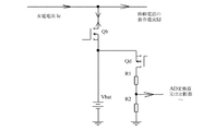
例えば、図3aに示すように、移動電話内のバッテリの電圧を検出するための具体的な検出回路において、スイッチQbがバッテリに直列に接続される。充電中に、スイッチQbはオンになる。バッテリの電圧が検出されているとき、スイッチQbはオフになる。充電電流と放電電流との双方が0であり、それにより、ケーブル及び内部抵抗の電圧降下が最小値まで低下する。同時にQdがオンになる。バッテリの電圧は、R1R2で除算され、バッテリの電圧を取得するために、バックエンドのアナログ・デジタル変換器又は比較器に送出される。 For example, as shown in FIG. 3a, in a specific detection circuit for detecting the voltage of a battery in a mobile phone, a switch Qb is connected in series with the battery. During charging, the switch Qb is turned on. When the voltage of the battery is detected, the switch Qb is turned off. Both the charging current and the discharging current are zero, which reduces the voltage drop of the cable and the internal resistance to a minimum. Qd is turned on at the same time. The battery voltage is divided by R1R2 and sent to the back-end analog-to-digital converter or comparator to obtain the battery voltage.
CPU150は、バッテリ140の正極と負極との間の電圧の値に従って命令情報を生成するように構成される。
送信機130は、命令情報を端末10に接続された充電器20に送出し、それにより、充電器20に対して出力電圧及び出力電流を調整するように命令するように構成される。
The transmitter 130 is configured to send command information to the
受信機170は、充電器から送信された出力電圧及び出力電流を受信するように構成され、受信機は、充電器に電気的に接続される。
The
変換回路120は、受信機170により受信された出力電圧を出力電圧の1/K倍に変換し、受信機170により受信された出力電流を出力電流のK倍に変換するように構成され、変換回路120は、固定の変換比を有する変換回路であり、変換係数Kは一定値であり、Kは1より大きい任意の実数である。
The
充電回路160は、出力電圧の1/K倍及び出力電流のK倍でバッテリ140を充電するように構成される。
The charging
任意選択で、変換回路は、buck回路又はスイッチ・キャパシタ変換回路である。 Optionally, the conversion circuit is a buck circuit or a switched capacitor conversion circuit.
例えば、図4に示すように、変換回路120は、固定のデューティサイクルを有するbuck方式を使用する。固定のデューティサイクルを有するbuckでは、スイッチングトランジスタQ1及びQ2はブリッジアームを形成する。駆動信号V1及びV2は、Q1及びQ2を交互にオンにし、直流電圧Vinを固定のデューティサイクルを有するパルス電圧に変換するように駆動し、Kの変換係数で電圧降下を実現する。直流電圧Voutは、インダクタL3のフィルタリングの後に出力され、Vout=Vin/Kである。効率的な充電を実現するために、デューティサイクルは最大値に固定される。さらに、固定のデューティサイクルを有するbuck方式では、複数のbuckが、多相buckを形成するように、位相の順序に従って並列に接続されてもよい。
For example, as shown in FIG. 4, the
例えば、図5に示すように、DC/DC変換モジュールは、さらにスイッチ・キャパシタ変換器でもよい。スイッチ・キャパシタ変換器内の4つのスイッチングトランジスタは直列に接続される。キャパシタC7は、Q1Q2の中間点とQ3Q4の中間点との間に接続される。V2〜V5は、スイッチングトランジスタのドライバである。V2及びV5は相補的である。V3及びV4は相補的である。2:1のスイッチ・キャパシタ変換器は、2:1の固定比で、入力電圧を入力電圧の半分に低下させてもよい。変換回路によりVinに対して実行された変換の後に、出力電圧は
![]()
![]()
端末10を充電するプロセスにおいて、バッテリ140の電圧は絶えず増加し、したがって、充電器に対して出力電流を調整するように絶えず命令することが要求されることが理解され得る。したがって、CPU150は、検出回路110により取得された電圧値を第1の予め設定された閾値と比較し、比較結果を取得し、比較結果に従って命令情報を生成するように更に構成される。送信機130は、命令情報を充電器に送出するように構成される。命令情報は、充電器に対して出力電流を調整するように命令するために使用される。例えば、第1の予め設定された閾値は3Vである。検出回路110は、バッテリの正極と負極との間の電圧の値を検出し、正極と負極との間の電圧の検出された値が2.5Vである。CPU150は、正極と負極との間の電圧の値が第1の予め設定された閾値未満であると決定し、充電器に対して低速充電方式で充電を実行するように命令する。検出された電圧値が3.5Vである場合、CPU150は、正極と負極との間の電圧の値が第1の予め設定された閾値より大きいと決定し、充電器に対して高速充電方式で充電を実行するように命令する。低速充電方式は、対応する出力電流を有する(これは電流値でもよく、或いは値の範囲でもよい)。高速充電方式もまた、対応する出力電流を有する(これは電流値でもよく、或いは値の範囲でもよい)。
In the process of charging the terminal 10, it can be seen that the voltage of the battery 140 is constantly increasing, thus requiring that the charger be constantly commanded to regulate the output current. Therefore, the
さらに、時間が経過すると、バッテリ140の電気量は絶えず蓄積され、次に、検出回路110はバッテリ140のバッテリレベルを検出し、バッテリ140が完全に充電されたか否かを決定する点に留意すべきである。したがって、CPU150は、バッテリ140の電圧が第2の予め設定された閾値に到達したことを検出したとき、切断通知を受信機170に送出するように更に構成される。受信機170は、切断通知に従って充電器への電気接続を切断するように構成される。任意選択で、バッテリ140の電圧が第2の予め設定された閾値に到達したことを検出したとき、CPU150は、充電器20に対してスリープモードに入るように更に命令してもよく、それにより、充電器が電力を供給するのを停止する。
Further, note that as time passes, the amount of electricity in battery 140 is constantly accumulated, and then
検出回路110は、バッテリ140の電流及びバッテリの充電の状態を検出するように更に構成されてもよい。電流が過度に大きいとき、又は充電が過度に急速に消費されたとき、検出回路110は、端末のインタフェース上で通知を与える。
The
本発明のこの実施例では、端末10は、メモリ180と、バスシステムとを更に含んでもよい点に留意すべきである。CPU150及びメモリは、バスシステムを使用することにより接続される。メモリは、命令を記憶するように構成される。プロセッサは、メモリに記憶された命令を実行するように構成され、それにより、端末10が高速充電方法を実行する。本発明のこの実施例では、CPU150は、他の汎用プロセッサ、Digital Signal Processor(DSP)、Application Specific Integrated Circuit(ASIC)、Field-Programmable Gate Array(FPGA)又は他のプログラム可能論理デバイス、ディスクリートゲート又はトランジスタ論理デバイス、ディスクリートハードウェアコンポーネント等でもよいことが理解されるべきである。汎用プロセッサはマイクロプロセッサでもよく、或いはプロセッサはいずれかの従来のプロセッサでもよい。メモリは、読み取り専用メモリと、ランダムアクセスメモリとを含み、CPUのために命令及びデータを提供してもよい。メモリの一部は、不揮発性ランダムアクセスメモリを更に含んでもよい。例えば、メモリは、デバイス種別についての情報を更に記憶してもよい。データバスに加えて、バスシステムは、電力バス、制御バス、状態信号バス等を含んでもよい。
It should be noted that in this embodiment of the present invention, terminal 10 may further include a memory 180 and a bus system. The
図3に示すように、FCSにおける充電器20は、受信機210と、電圧調整回路220と、電流調整回路230とを含む。
As shown in FIG. 3, the
受信機210は、端末10により送出された命令情報を受信するように構成され、命令情報は、端末10内のバッテリの正極と負極との間の電圧の値と、正極と負極との間の電圧の値のK倍とを含み、Kは1より大きい任意の実数である。 The receiver 210 is configured to receive the command information sent by the terminal 10, and the command information includes a value of a voltage between the positive electrode and the negative electrode of the battery in the terminal 10, and a value between the positive electrode and the negative electrode. And K is any real number greater than one.
電圧調整回路220は、出力電圧の電圧値をバッテリの正極と負極との間の電圧の値のK倍に調整するように構成される。 The voltage adjustment circuit 220 is configured to adjust the voltage value of the output voltage to K times the value of the voltage between the positive electrode and the negative electrode of the battery.
電流調整回路230は、バッテリの正極と負極との間の電圧の値に従って充電モードを決定し、充電モードに対応する電流値を取得し、対応する電流値に従って出力電流を調整するように構成される。
The
任意選択で、充電器は電源に接続される。したがって、充電器は、電源により提供される交流を直流に変換するための交流/直流変換モジュールを含む。 Optionally, the charger is connected to a power supply. Accordingly, the charger includes an AC / DC conversion module for converting AC provided by the power supply into DC.
本発明では、端末は、固定の変換比を有するDC/DC変換方式を使用し、固定のデューティサイクルで動作し、バッテリのリアルタイムの電圧フィードバックに基づいて充電器の出力電圧及び出力電流を絶えず調整することが理解され得る。DC/DC変換方式の変換効率は、より高く、それにより、移動電話側のバッテリに出力される充電電流がより大きくなることができ、全体のFCSの充電効率が有効に改善され、それにより、高速充電時間を有効に短縮する。 In the present invention, the terminal uses a DC / DC conversion scheme with a fixed conversion ratio, operates at a fixed duty cycle, and constantly adjusts the charger output voltage and output current based on real-time battery voltage feedback. It can be understood that The conversion efficiency of the DC / DC conversion method is higher, so that the charging current output to the battery on the mobile phone side can be larger, and the charging efficiency of the whole FCS is effectively improved, Effectively reduce fast charging time.
図1における高速充電システムについて、本発明の実施例は充電方法を更に提供する。方法は、端末側の方法と、充電器側の方法とを含む。 For the fast charging system in FIG. 1, the embodiment of the present invention further provides a charging method. The method includes a terminal-side method and a charger-side method.
図6に示すように、端末側の高速充電方法は以下のステップを含む。 As shown in FIG. 6, the high-speed charging method on the terminal side includes the following steps.
S301.端末10は、端末10内のバッテリの正極と負極との間の電圧の値を検出する。 S301. The terminal 10 detects the value of the voltage between the positive electrode and the negative electrode of the battery in the terminal 10.
S302.端末10は、バッテリの正極と負極との間の電圧の値に従って命令情報を生成し、命令情報を端末10に接続された充電器に送出し、それにより、充電器20に対して出力電圧及び出力電流を調整するように命令する。
S302. The terminal 10 generates command information according to the value of the voltage between the positive electrode and the negative electrode of the battery, and sends the command information to the charger connected to the terminal 10, thereby outputting the command information to the
S303.端末10は、充電器の出力電圧を出力電圧の1/K倍に変換し、充電器20の出力電流を出力電流のK倍に変換し、Kは端末10内の固定の変換比を有する変換回路の変換係数であり、Kは一定値であり、Kは1より大きい任意の実数である。
S303. The terminal 10 converts the output voltage of the charger to 1 / K times the output voltage, converts the output current of the
S304.端末10は、出力電圧の1/K倍及び出力電流のK倍でバッテリを充電する。 S304. The terminal 10 charges the battery at 1 / K times the output voltage and K times the output current.
高速充電プロセスにおいて、端末10内のバッテリの正極と負極との間の電圧は絶えず変化し、バッテリは、バッテリの異なる電圧範囲に従って異なる電流で充電される必要があることが理解され得る。 In the fast charging process, it can be seen that the voltage between the positive and negative electrodes of the battery in the terminal 10 constantly changes and the battery needs to be charged with different currents according to different voltage ranges of the battery.
したがって、端末がバッテリの正極と負極との間の電圧の値に従って命令情報を生成することは以下を含む。 Therefore, generating the command information according to the value of the voltage between the positive electrode and the negative electrode of the battery includes the following.
端末は、正極と負極との間の電圧の値を第1の予め設定された閾値と比較し、比較結果を取得し、比較結果に従って命令情報を生成する。さらに、端末10は、バッテリが完全に充電されたか否かを絶えず検出する必要があり、バッテリが完全に充電されたとき、充電器20に対して充電を停止するか、或いは充電器20への電気接続を切断するように命令する必要がある点に留意すべきである。任意選択で、端末10は、バッテリの正極と負極との間の電圧が第2の予め設定された閾値に到達したか否かを検出してもよく、バッテリの正極と負極との間の電圧が第2の予め設定された閾値に到達したことを検出したとき、端末と充電器との間の電気接続を切断する。
The terminal compares the value of the voltage between the positive electrode and the negative electrode with a first preset threshold, acquires a comparison result, and generates command information according to the comparison result. In addition, the terminal 10 must constantly detect whether the battery is fully charged, and when the battery is fully charged, stop charging the
図7に示すように、充電器20側の高速充電方法は以下のステップを含む。
As shown in FIG. 7, the high-speed charging method on the
S401.充電器20は、端末により送出された命令情報を受信し、命令情報は、端末10内のバッテリの正極と負極との間の電圧の値を含む。
S401. The
S402.充電器20は、出力電圧の電圧値をバッテリの正極と負極との間の電圧の値のK倍に調整し、Kは1より大きい任意の実数であり、Kは充電器に予め記憶された電圧調整係数である。
S402. The
S403.充電器20は、バッテリの正極と負極との間の電圧の値に従って充電モードを決定し、充電モードに対応する電流値を取得し、対応する電流値に従って出力電流を調整する。
S403. The
図8に示すように、充電器20側の高速充電方法は以下のステップを更に含む。
As shown in FIG. 8, the high-speed charging method on the
S501.充電器20は、端末10により送出された命令情報を受信し、命令情報は、端末10内のバッテリの正極と負極との間の電圧の値と、正極と負極との間の電圧の値のK倍とを含み、Kは1より大きい任意の実数である。
S501.The
S502.充電器20は、出力電圧の電圧値をバッテリの正極と負極との間の電圧の値のK倍に調整する。
S502. The
S503.充電器20は、バッテリの正極と負極との間の電圧の値に従って充電モードを決定し、充電モードに対応する電流値を取得し、対応する電流値に従って出力電流を調整する。
S503. The
本発明では、端末は、固定の変換比を有するDC/DC変換方式を使用し、固定のデューティサイクルで動作し、バッテリのリアルタイムの電圧フィードバックに基づいて充電器の出力電圧及び出力電流を絶えず調整することが理解され得る。DC/DC変換方式の変換効率は、より高く、それにより、移動電話側のバッテリに出力される充電電流がより大きくなることができ、全体のFCSの充電効率が有効に改善され、それにより、高速充電時間を短縮する。 In the present invention, the terminal uses a DC / DC conversion scheme with a fixed conversion ratio, operates at a fixed duty cycle, and constantly adjusts the charger output voltage and output current based on real-time battery voltage feedback. It can be understood that The conversion efficiency of the DC / DC conversion method is higher, so that the charging current output to the battery on the mobile phone side can be larger, and the charging efficiency of the whole FCS is effectively improved, Reduce fast charging time.
本発明において提供される他の高速充電の実施例では、充電器及び移動電話が説明のための例として使用される。 In other fast charging embodiments provided in the present invention, a charger and a mobile phone are used as illustrative examples.
(1)充電器は、移動電話に接続される。 (1) The charger is connected to the mobile phone.
(2)バッテリの電圧が移動電話において検出され、電圧値Vを取得し、2Vがデータケーブルを使用することにより充電器に送出されるか、或いは無線ネットワークを使用することにより充電器に送出されてもよい(移動電話内の固定の変換比を有する変換回路の変換係数Kは2に等しいことが仮定される)。 (2) The voltage of the battery is detected in the mobile phone, obtains the voltage value V, and 2V is sent to the charger by using a data cable or sent to the charger by using a wireless network. (The conversion factor K of the conversion circuit with a fixed conversion ratio in the mobile telephone is assumed to be equal to 2).
(3)電圧情報を受信した後に、充電器は、まず、出力電圧を2V又は2V×(1+x%)に調整し、バッテリが入力端に向かって電流を逆送りすることを妨げる。xの値の範囲は1〜10である(1及び10を含む)。 (3) After receiving the voltage information, the charger first adjusts the output voltage to 2V or 2V × (1 + x%) to prevent the battery from feeding back the current toward the input terminal. The value of x ranges from 1 to 10 (inclusive) .
(4)充電器は、移動電話に対して充電を有効にするように命令する。 (4) The charger instructs the mobile phone to enable charging.
(5)充電器は、高速充電が実行できるか否かを決定する。例えば、バッテリの電圧が2.7Vに過ぎないとき、充電器は、電流を小電流に調整し、バッテリの電圧が3Vに到達するまで、小電流でプリチャージを実行する。次に、充電器は、電流を4Aに調整し、端末は、変換係数に従って8Aで高速充電される。 (5) The charger determines whether high-speed charging can be performed. For example, when the battery voltage is only 2.7V, the charger adjusts the current to a small current and performs the precharge with the small current until the battery voltage reaches 3V. Next, the charger regulates the current to 4A, and the terminal is fast charged at 8A according to the conversion factor.
(6)移動電話を充電するプロセスにおいて、バッテリの電圧は、予め設定された時間間隔で検出され、バッテリの電圧に従って、充電器に対して電流の値を調整するように命令するか否かが決定される。バッテリの電圧を検出する時点で、充電が停止されてもよく、或いは充電電流が低減されてもよい。 (6) In the process of charging the mobile phone, the voltage of the battery is detected at a preset time interval, and it is determined whether or not to instruct the charger to adjust the value of the current according to the voltage of the battery. It is determined. At the time of detecting the voltage of the battery, the charging may be stopped, or the charging current may be reduced.
例えば、バッテリの電圧が4.2Vに近いとき(例えば、4.15Vに到達したとき)、移動電話は、充電器に対して小電流充電状態又は一定電圧充電状態に入るように命令する。充電後に電圧が4.2Vに到達したとき、充電が停止する。高速充電プロセスにおいて、バッテリの電圧が増加すると、電流が減少してもよい。電流は、段階方式又は連続方式で減少してもよい。充電プロセスにおいて、連続的な直流に加えて、不連続的なパルス電流が充電のために使用されてもよい。 For example, when the battery voltage is near 4.2V (eg, when it reaches 4.15V), the mobile phone commands the charger to enter a low current charging state or a constant voltage charging state. When the voltage reaches 4.2V after charging, charging stops. In a fast charging process, the current may decrease as the battery voltage increases. The current may be reduced in a stepwise or continuous manner. In the charging process, a discontinuous pulsed current may be used for charging in addition to a continuous direct current.
(7)充電が停止した後に、以下の状態のうち1つに入ってもよい。 (7) After charging is stopped, one of the following states may be entered.
A.充電器は、もはや電流を移動電話に供給しない。移動電話の動作電流は、バッテリにより供給される。この状態では、放電後にバッテリの電圧が或る値に到達したとき、例えば、電圧が4.1Vまで低下したとき、充電が復旧する。 A. The charger no longer supplies current to the mobile phone. The operating current of the mobile phone is supplied by a battery. In this state, when the battery voltage reaches a certain value after discharging, for example, when the voltage drops to 4.1 V, charging is restored.
B.充電器は、動作電流を移動電話に供給するが、バッテリに充電するために使用される経路は切断され、充電電流をバッテリに供給しない。この場合、バッテリは、電力を移動電話に供給せず、充電器と移動電話との間の接続が切断されるまで、常に完全充電状態になる。 B. The charger supplies operating current to the mobile phone, but the path used to charge the battery is broken and does not supply charging current to the battery. In this case, the battery will not supply power to the mobile phone and will always be fully charged until the connection between the charger and the mobile phone is broken.
本発明の他の高速充電の実施例では、具体的なパルス電流充電実現方式が提供される。図9に示すように、図9の上部は、パルス電流波形であり、図9の下部は、バッテリの電圧が充電後により高くなったときの波形である。横座標は時間を表し、縦座標は充電電流を表す。 In another fast charging embodiment of the present invention, a specific pulse current charging realization method is provided. As shown in FIG. 9, the upper part of FIG. 9 shows a pulse current waveform, and the lower part of FIG. 9 shows a waveform when the voltage of the battery becomes higher after charging. The abscissa represents time and the ordinate represents charging current.
T on の期間中に、充電電流は比較的大きい値であり、バッテリの電圧は上昇する。 During the period of T on, the charging current is relatively large value, the voltage of the battery rises.
T off の期間中に、電流は0又は比較的小さい値であり、バッテリの電圧は低下する。T off の期間中に、バッテリの電圧が検出されてもよい。 During T off , the current is zero or a relatively small value, and the battery voltage drops. During the period of T off , the voltage of the battery may be detected.
T on の期間中の電流値はまた、バッテリの電圧に従って変化してもよい。例えば、まず、バッテリの電圧は3Vであり、T on の期間中の電流は8Aである。バッテリの電圧が4.0Vに到達したとき、電流は小さい値、すなわち、6Aに調整される。バッテリの電圧が4.15Vに到達したとき、バッテリが完全に充電されるまで、電流は小さい値、すなわち、3Aに調整される。 Current value during the T on may also vary according to the voltage of the battery. For example, first, the voltage of the battery is 3V, the current during the period T on is 8A. When the battery voltage reaches 4.0V, the current is adjusted to a small value, ie, 6A. When the battery voltage reaches 4.15V, the current is adjusted to a small value, ie, 3A, until the battery is fully charged.
T off の期間の値は変化してもよい。例えば、バッテリの電圧が4.2Vに到達したとき、バッテリレベルが完全バッテリレベルにより近くなると、T off の期間はより長くなる。T off の期間がより長くなるプロセスは、バッテリの電圧を検出することにより実現されてもよい。
The value of the period of T off may change. For example, when the battery voltage reaches 4.2V, the duration of T off will be longer if the battery level is closer to the full battery level. A process in which the period of T off becomes longer may be realized by detecting the voltage of the battery.
例えば、充電パルスの後に、バッテリの電圧は、わずかに4.2Vを必然的に超える。次に、パルスが終了した後に、バッテリの電圧は低下し始め、電圧が4.18Vまで低下したとき、他のパルスが到来する。より高いバッテリレベルは、電圧が4.18Vまで低下するのに、より長い時間を必然的にもたらす。時間が十分長いとき、バッテリが完全に充電されたと考えられ、端末と充電器との間の電気接続が切断できる。 For example, after a charge pulse, the voltage of the battery necessarily exceeds just 4.2V. Then, after the end of the pulse, the voltage of the battery begins to drop, and when the voltage drops to 4.18V, another pulse arrives. Higher battery levels necessarily result in a longer time for the voltage to drop to 4.18V. When the time is long enough, the battery is considered fully charged and the electrical connection between the terminal and the charger can be broken.
当業者は、この明細書に開示された実施例に記載の例と組み合わせて、ユニット及びアルゴリズムのステップが、電子ハードウェア、又はコンピュータソフトウェアと電子ハードウェアとの組み合わせにより実現されてもよいことを認識し得る。機能がハードウェアにより実行されるかソフトウェアにより実行されるかは、技術的解決策の特定の用途及び設計上の制約条件に依存する。当業者は、特定の用途毎に記載の機能を実現するために異なる方法を使用してもよいが、その実現方式が本発明の範囲を超えると考えられるべきではない。 Those skilled in the art will appreciate that, in combination with the examples described in the embodiments disclosed herein, the steps of the units and algorithms may be realized by electronic hardware or a combination of computer software and electronic hardware. Can recognize. Whether a function is performed by hardware or software depends on the particular application of the technical solution and design constraints. One skilled in the art may use different methods to implement the described functionality for a particular application, but such implementation is not to be considered as beyond the scope of the present invention.
便宜上且つ簡潔な説明の目的で、前述のシステム、装置及びユニットの詳細な動作プロセスについて、前述の方法の実施例における対応するプロセスに参照が行われてもよく、詳細はここでは再び説明しないことが当業者により明確に理解され得る。 For convenience and for the sake of brevity, reference may be made to the corresponding processes in the above-described method embodiments for the detailed operating processes of the systems, devices and units described above, and details will not be described again here. Can be clearly understood by those skilled in the art.
この出願において提供されるいくつかの実施例において、開示のシステム、装置及び方法は、他の方式で実現されてもよいことが理解されるべきである。例えば、記載の装置の実施例は、単なる例である。例えば、ユニットの分割は、単に論理的な機能分割であり、実際の実現方式では他の分割でもよい。例えば、複数のユニット又はコンポーネントは結合されてもよく、或いは他のシステムに統合されてもよく、或いはいくつかの特徴が無視されてもよく或いは実行されなくてもよい。さらに、表示又は説明した相互結合若しくは直接結合又は通信接続は、いくつかのインタフェースを使用することにより実現されてもよい。装置又はユニットの間の間接結合又は通信接続は、電子的、機械的又は他の形式で実現されてもよい。 It should be understood that in some embodiments provided in this application, the disclosed systems, devices, and methods may be implemented in other manners. For example, the described device embodiment is merely an example. For example, the division of a unit is simply a logical division of functions, and another division may be used in an actual realization method. For example, multiple units or components may be combined or integrated into other systems, or some features may be ignored or not performed. Further, the interconnections or direct couplings or communication connections shown or described may be achieved through the use of several interfaces. Indirect coupling or communication connections between devices or units may be implemented electronically, mechanically, or in other forms.
別々の部分として記載したユニットは、物理的に別々でもよく或いは別々でなくてもよく、ユニットとして表示された部分は、物理的なユニットでもよく或いは物理的なユニットでなくてもよく、1つの場所に位置してもよく、或いは複数のネットワークユニットに分散されてもよい。ユニットの一部又は全部は、実施例の解決策の目的を達成するために、実際の要件に従って選択されてもよい。 Units described as separate parts may or may not be physically separate, and parts designated as units may or may not be physical units, and It may be located at a location or distributed over multiple network units. Some or all of the units may be selected according to actual requirements to achieve the objectives of the solution of the embodiment.
さらに、本発明の実施例における機能ユニットは、1つの処理ユニットに統合されてもよく、或いはユニットのそれぞれが物理的に単独で存在してもよく、或いは2つ以上のユニットが1つのユニットに統合される。 Further, the functional units in embodiments of the present invention may be integrated into one processing unit, or each of the units may physically exist alone, or two or more units may be combined into one unit. Be integrated.
機能がソフトウェア機能ユニットの形式で実現され、独立したプロダクトとして販売又は使用されるとき、機能は、コンピュータ読み取り可能記憶媒体に記憶されてもよい。このような理解に基づいて、本発明の技術的解決策は、本質的に、或いは、従来技術に寄与する部分又は技術的解決策のいくつかは、ソフトウェアプロダクトの形式で実現されてもよい。ソフトウェアプロダクトは、記憶媒体に記憶され、コンピュータデバイス(パーソナルコンピュータ、サーバ又はネットワークデバイスでもよい)に対して本発明の実施例に記載の方法のステップの全部又は一部を実行するように命令するためのいくつかの命令を含む。前述の記憶媒体は、USBフラッシュドライブ、取り外し可能ハードディスク、読み取り専用メモリ(ROM, Read-Only Memory)、ランダムアクセスメモリ(RAM, Random Access Memory)、磁気ディスク又は光ディスクのようなプログラムコードを記憶できるいずれかの媒体を含む。 When a function is implemented in the form of a software functional unit and sold or used as a separate product, the function may be stored on a computer-readable storage medium. Based on this understanding, the technical solutions of the present invention may be realized in essence, or some of the technical solutions or parts that contribute to the prior art may be implemented in the form of software products. The software product is stored on a storage medium for instructing a computing device (which may be a personal computer, a server or a network device) to perform all or some of the steps of the method according to embodiments of the present invention. Including some instructions. The above-mentioned storage medium may be a USB flash drive, a removable hard disk, a read-only memory (ROM, Read-Only Memory), a random access memory (RAM, Random Access Memory), any of which can store a program code such as a magnetic disk or an optical disk. Including such media.
前述の説明は、本発明の単に具体的な実現方式に過ぎず、本発明の保護範囲を限定することを意図するものではない。本発明に開示された技術的範囲内で当業者により容易に理解される如何なる変更又は置換も本発明の保護範囲内に入るものとする。したがって、本発明の保護範囲は、特許請求の範囲の保護範囲に従うものとする。 The above description is merely illustrative of the mode of realization of the present invention, and is not intended to limit the protection scope of the present invention. Any change or replacement readily figured out by a person skilled in the art within the technical scope disclosed in the present invention shall fall within the protection scope of the present invention. Therefore, the protection scope of the present invention shall be subject to the protection scope of the claims.
Claims (9)
前記検出回路は、前記バッテリの正極と負極との間の電圧の値を検出するように構成され、
前記CPUは、前記バッテリの前記正極と前記負極との間の前記電圧の前記値に従って命令情報を生成するように構成され、
前記送信機は、前記命令情報を前記端末に接続された充電器に送出し、それにより、前記充電器に対して出力電圧及び出力電流を調整するように命令するように構成され、
前記受信機は、前記充電器から送信された前記出力電圧及び前記出力電流を受信するように構成され、前記受信機は、前記充電器に電気的に接続され、
前記変換回路は、前記受信機により受信された前記出力電圧を前記出力電圧の1/K倍に変換し、前記受信機により受信された前記出力電流を前記出力電流のK倍に変換するように構成され、前記変換回路は、固定の変換比を有する変換回路であり、変換係数Kは一定値であり、Kは1より大きい任意の実数であり、
前記充電回路は、前記出力電圧の前記1/K倍及び前記出力電流の前記K倍で前記バッテリを充電するように構成される、端末。 A terminal including a detection circuit, a conversion circuit, a transmitter, a receiver, a central processing unit (CPU), a charging circuit, and a battery,
The detection circuit is configured to detect a value of a voltage between a positive electrode and a negative electrode of the battery,
The CPU is configured to generate command information according to the value of the voltage between the positive electrode and the negative electrode of the battery,
The transmitter is configured to send the command information to a charger connected to the terminal, thereby instructing the charger to adjust an output voltage and an output current;
The receiver is configured to receive the output voltage and the output current transmitted from the charger, and the receiver is electrically connected to the charger.
The conversion circuit converts the output voltage received by the receiver to 1 / K times the output voltage, and converts the output current received by the receiver to K times the output current. The conversion circuit is a conversion circuit having a fixed conversion ratio, the conversion coefficient K is a constant value, K is any real number greater than 1,
The terminal, wherein the charging circuit is configured to charge the battery at the 1 / K times the output voltage and the K times the output current.
前記受信機は、前記切断通知に従って前記充電器への電気接続を切断するように構成される、請求項1又は2に記載の端末。 The CPU, when detecting that the value of the voltage between the positive electrode and the negative electrode of the battery has reached a second preset threshold, sends a disconnection notification to the receiver. Further configured,
The terminal according to claim 1 or 2, wherein the receiver is configured to disconnect an electrical connection to the charger according to the disconnection notification.
前記端末は、前記端末内のバッテリの正極と負極との間の電圧の値を取得するように構成され、
前記端末は、前記バッテリの前記正極と前記負極との間の前記電圧の前記値に従って命令情報を生成し、前記命令情報を前記充電器に送出するように更に構成され、
前記充電器は、前記命令情報に従って出力電圧の電圧値を前記バッテリの前記正極と前記負極との間の前記電圧の前記値のK倍に調整するように構成され、Kは1より大きい任意の実数であり、
前記充電器は、前記命令情報に従って充電モードを決定し、前記充電モードに対応する電流値を取得し、前記対応する電流値に従って出力電流を調整するように更に構成され、
前記端末は、前記充電器の前記出力電圧を前記出力電圧の1/K倍に変換し、前記充電器の前記出力電流を前記出力電流のK倍に変換するように構成され、それにより、前記バッテリの両端の間の充電回路は、前記出力電圧の前記1/K倍及び前記出力電流の前記K倍で前記バッテリを充電し、Kは前記端末内の固定の変換比を有する変換回路の変換係数であり、一定値である、システム。 A high-speed charging system including a terminal, a charger, and a connection cable, wherein the terminal is connected to the charger by using the connection cable,
The terminal is configured to obtain a value of a voltage between a positive electrode and a negative electrode of a battery in the terminal,
The terminal is further configured to generate command information according to the value of the voltage between the positive electrode and the negative electrode of the battery, and send the command information to the charger.
The charger is configured to adjust a voltage value of an output voltage to K times the value of the voltage between the positive electrode and the negative electrode of the battery according to the command information, where K is any value greater than 1. Real number,
The charger is further configured to determine a charging mode according to the command information, obtain a current value corresponding to the charging mode, and adjust an output current according to the corresponding current value;
The terminal is configured to convert the output voltage of the charger to 1 / K times the output voltage and to convert the output current of the charger to K times the output current, whereby the terminal A charging circuit across the battery charges the battery at the 1 / K times the output voltage and the K times the output current, where K is the conversion of the conversion circuit having a fixed conversion ratio in the terminal. A system that is a coefficient and a constant value.
前記正極と前記負極との間の前記電圧の前記値を第1の予め設定された閾値と比較し、比較結果を取得し、前記比較結果に従って前記命令情報を生成することを含む、請求項4に記載のシステム。 Wherein the terminal is configured to generate command information according to the value of the voltage between the positive electrode and the negative electrode of the battery,
5. The method according to claim 4 , further comprising: comparing the value of the voltage between the positive electrode and the negative electrode with a first preset threshold, obtaining a comparison result, and generating the command information according to the comparison result. System.
端末により、前記端末内のバッテリの正極と負極との間の電圧の値を検出するステップと、
前記端末により、前記バッテリの前記正極と前記負極との間の前記電圧の前記値に従って命令情報を生成するステップと、
前記端末により、前記命令情報を前記端末に接続された充電器に送出し、それにより、前記充電器に対して出力電圧及び出力電流を調整するように命令するステップと、
前記端末により、前記充電器から送信された前記出力電圧及び前記出力電流を受信するステップと、
前記端末により、前記充電器の前記出力電圧を前記出力電圧の1/K倍に変換し、前記充電器の前記出力電流を前記出力電流のK倍に変換するステップであり、Kは前記端末内の固定の変換比を有する変換回路の変換係数であり、Kは一定値であり、Kは1より大きい任意の実数である、ステップと、
前記端末により、前記出力電圧の前記1/K倍及び前記出力電流の前記K倍で前記バッテリを充電するステップと
を含む方法。 A fast charging method,
Detecting, by a terminal, a value of a voltage between a positive electrode and a negative electrode of a battery in the terminal;
The terminal generating command information according to the value of the voltage between the positive electrode and the negative electrode of the battery;
Sending, by the terminal, the command information to a charger connected to the terminal, thereby instructing the charger to adjust an output voltage and an output current;
Receiving, by the terminal, the output voltage and the output current transmitted from the charger;
Converting, by the terminal, the output voltage of the charger to 1 / K times the output voltage, and converting the output current of the charger to K times the output current, wherein K is within the terminal. A conversion factor of a conversion circuit having a fixed conversion ratio of, K is a constant value, and K is any real number greater than 1, a step;
Charging the battery with the terminal at the 1 / K times the output voltage and the K times the output current.
前記端末により、前記正極と前記負極との間の前記電圧の前記値を第1の予め設定された閾値と比較し、比較結果を取得し、前記比較結果に従って前記命令情報を生成するステップを含む、請求項7に記載の方法。 By the terminal, generating command information according to the value of the voltage between the positive electrode and the negative electrode of the battery,
The terminal includes comparing the value of the voltage between the positive electrode and the negative electrode with a first preset threshold, obtaining a comparison result, and generating the command information according to the comparison result. The method of claim 7 .
Applications Claiming Priority (3)
| Application Number | Priority Date | Filing Date | Title |
|---|---|---|---|
| CN201610218184.8 | 2016-04-08 | ||
| CN201610218184.8A CN107231012B (en) | 2016-04-08 | 2016-04-08 | A kind of method of quick charge, terminal, charger and system |
| PCT/CN2017/078098 WO2017173937A1 (en) | 2016-04-08 | 2017-03-24 | Fast charging method, terminal, charger and system |
Publications (2)
| Publication Number | Publication Date |
|---|---|
| JP2019511197A JP2019511197A (en) | 2019-04-18 |
| JP6669931B2 true JP6669931B2 (en) | 2020-03-18 |
Family
ID=59932828
Family Applications (1)
| Application Number | Title | Priority Date | Filing Date |
|---|---|---|---|
| JP2019500725A Active JP6669931B2 (en) | 2016-04-08 | 2017-03-24 | Fast charging method and system, terminal and charger |
Country Status (8)
| Country | Link |
|---|---|
| US (4) | US10734830B2 (en) |
| EP (3) | EP3654487B1 (en) |
| JP (1) | JP6669931B2 (en) |
| KR (1) | KR102220839B1 (en) |
| CN (3) | CN107231012B (en) |
| DE (1) | DE202017007596U1 (en) |
| ES (2) | ES2951335T3 (en) |
| WO (1) | WO2017173937A1 (en) |
Families Citing this family (12)
| Publication number | Priority date | Publication date | Assignee | Title |
|---|---|---|---|---|
| CN107231013B (en) * | 2016-05-24 | 2019-01-15 | 华为技术有限公司 | A kind of method of charging, terminal, charger and system |
| EP3454448A4 (en) * | 2016-06-01 | 2019-08-07 | Huawei Technologies Co., Ltd. | Charging method and terminal |
| CN108258348B (en) * | 2018-02-13 | 2022-04-29 | 中兴通讯股份有限公司 | Charging method, charging device, charging system, charging circuit, terminal and charging system |
| EP3796520A4 (en) * | 2018-06-08 | 2021-05-05 | Huawei Technologies Co., Ltd. | Wireless charging device, and terminal using same |
| CN108849611A (en) * | 2018-06-14 | 2018-11-23 | 北京北科驿唐科技有限公司 | A kind of electricity saving method and device for Pet loss preventer |
| CN110957773B (en) * | 2019-10-29 | 2022-04-01 | 大族激光科技产业集团股份有限公司 | High-voltage direct-current charging system |
| CN111416408A (en) * | 2020-03-09 | 2020-07-14 | 长兴永烜机械有限公司 | Charger and charging control method thereof |
| CN111509962A (en) * | 2020-05-26 | 2020-08-07 | 深圳市雷能混合集成电路有限公司 | Control method and device for preventing current backflow and power supply equipment |
| CN114079317B (en) * | 2020-08-19 | 2024-02-02 | 广州贵冠科技有限公司 | Quick-charging type charging device of mobile electronic device |
| TWI740615B (en) * | 2020-08-19 | 2021-09-21 | 僑威科技股份有限公司 | Fast charging device for mobile electronic device |
| JP6865879B1 (en) | 2020-09-07 | 2021-04-28 | 日本たばこ産業株式会社 | Aerosol generation system, aspirator controller, and power supply |
| CN112491112A (en) * | 2020-11-18 | 2021-03-12 | 惠州Tcl移动通信有限公司 | Mobile terminal charger and charging method thereof |
Family Cites Families (43)
| Publication number | Priority date | Publication date | Assignee | Title |
|---|---|---|---|---|
| CA2022802A1 (en) * | 1989-12-05 | 1991-06-06 | Steven E. Koenck | Fast battery charging system and method |
| JP2914259B2 (en) * | 1995-12-14 | 1999-06-28 | 日本電気株式会社 | Portable electronic device and charge control method for portable electronic device |
| JPH11103538A (en) * | 1997-09-27 | 1999-04-13 | My Way Giken Kk | Optical power generating system |
| US7336054B2 (en) * | 1998-08-14 | 2008-02-26 | Milwaukee Electric Tool Corporation | Apparatus and method of activating a microcontroller |
| US6172481B1 (en) | 1999-09-02 | 2001-01-09 | Qualcomm Incorporated | Method and apparatus for rapid charging batteries under sub-optimal interconnect conditions |
| CA2374342C (en) * | 2001-03-01 | 2005-12-20 | Research In Motion Limited | System and method for powering and charging a mobile communication device |
| CA2456608C (en) * | 2003-01-31 | 2009-01-06 | Universidad Tecnica Federico Santa Maria | A system to determine and analyze the dynamic internal load in revolving mills, for mineral grinding |
| US7135836B2 (en) * | 2003-03-28 | 2006-11-14 | Power Designers, Llc | Modular and reconfigurable rapid battery charger |
| US20050096518A1 (en) * | 2003-10-31 | 2005-05-05 | Yu-Hong Chang | Biological test system |
| JP4820257B2 (en) * | 2006-09-28 | 2011-11-24 | パナソニック株式会社 | Boost converter |
| US7937058B2 (en) * | 2006-10-18 | 2011-05-03 | Freescale Semiconductor, Inc. | Controlling the bandwidth of an analog filter |
| WO2008074158A1 (en) * | 2006-12-21 | 2008-06-26 | Icera Canada ULC | Closed-loop digital power control for a wireless transmitter |
| US8427113B2 (en) * | 2007-08-01 | 2013-04-23 | Intersil Americas LLC | Voltage converter with combined buck converter and capacitive voltage divider |
| US8405361B2 (en) | 2007-09-21 | 2013-03-26 | Qualcomm Incorporated | System and method for charging a rechargeable battery |
| US20090174366A1 (en) * | 2008-01-09 | 2009-07-09 | Freescale Semiconductor, Inc. | Multiple Function Switching Regulator for Use in Mobile Electronic Devices |
| US8278871B2 (en) * | 2009-04-03 | 2012-10-02 | Medtronic, Inc. | Open-loop recharge for an implantable medical device |
| KR101576182B1 (en) * | 2009-05-28 | 2015-12-10 | 삼성전자주식회사 | Method and apparatus for charge control of a portable terminal having solar battery |
| TWM385858U (en) * | 2010-02-12 | 2010-08-01 | Fu Da Tong Technology Co Ltd | Frequency conversion type wireless power supply and charging device |
| US9252463B2 (en) * | 2010-10-21 | 2016-02-02 | Chervon (Hk) Limited | Battery charging system having multiple charging modes |
| DE102012101769A1 (en) * | 2012-03-02 | 2013-09-05 | Phoenix Contact Gmbh & Co. Kg | Control module for an electrical energy storage, energy storage unit with such a control module, uninterruptible power supply device and method for operating a control module |
| CN102769156B (en) | 2012-07-17 | 2015-04-22 | 广东欧珀移动通信有限公司 | Quick charging method |
| JP5955714B2 (en) * | 2012-09-18 | 2016-07-20 | 株式会社東芝 | Battery pack and electric vehicle |
| WO2014077978A1 (en) | 2012-11-14 | 2014-05-22 | Apple Inc. | High voltage charging for a portable device |
| CN103078372A (en) * | 2012-12-29 | 2013-05-01 | 杭州汇点网络科技有限公司 | Method for charging electric automobile in multi-battery pack mode |
| CN103107575B (en) * | 2013-01-18 | 2015-07-29 | 华为终端有限公司 | Charging method, mobile device, charging device and charging system |
| KR20140120699A (en) * | 2013-04-04 | 2014-10-14 | 삼성전자주식회사 | Control Method for Charging and Electronic Device, and Charging Device supporting the same |
| CN104321960B (en) | 2013-04-22 | 2017-09-22 | 联发科技股份有限公司 | Switch mode charger for charging system |
| CN103236568B (en) * | 2013-05-03 | 2016-03-30 | 努比亚技术有限公司 | Charging method and charging system |
| US9590436B2 (en) | 2013-05-24 | 2017-03-07 | Qualcomm Incorporated | Master-slave multi-phase charging |
| US9356460B2 (en) | 2013-08-05 | 2016-05-31 | Texas Instruments Incorporated | Method and apparatus of fast battery charging with universal high power input source |
| CN105518969A (en) | 2013-09-09 | 2016-04-20 | 苹果公司 | Battery charger with buck-boost operation |
| US9444281B2 (en) | 2014-01-03 | 2016-09-13 | Apple Inc. | Unified high power and low power battery charger |
| CN106532884B (en) * | 2014-01-28 | 2019-07-19 | Oppo广东移动通信有限公司 | Battery charger and method |
| CN108134432B (en) * | 2014-01-28 | 2021-01-15 | Oppo广东移动通信有限公司 | Electronic equipment charging control device and method |
| CN106385094B (en) * | 2014-01-28 | 2019-02-12 | Oppo广东移动通信有限公司 | Control method for quickly charging and system |
| CN106253427B (en) | 2014-01-28 | 2018-05-29 | 广东欧珀移动通信有限公司 | Terminal and its battery charging control device and method |
| US10601251B2 (en) * | 2014-08-12 | 2020-03-24 | Apple Inc. | System and method for power transfer |
| CN104505888B (en) | 2014-12-24 | 2016-08-17 | 广东欧珀移动通信有限公司 | A kind of mobile terminal and charging device |
| EP3241224A4 (en) * | 2014-12-29 | 2018-05-30 | Energous Corporation | Systems and methods for wireless power transmission |
| CN104600796B (en) * | 2014-12-30 | 2019-09-20 | 惠州Tcl移动通信有限公司 | The mobile terminal and method of quick charge, system |
| CN204578156U (en) * | 2015-04-27 | 2015-08-19 | 南通理工学院 | Quick charging controller for storage battery |
| US9748788B2 (en) * | 2015-09-17 | 2017-08-29 | Qualcomm Incorporated | Systems and methods for charging a battery |
| US10734839B2 (en) * | 2017-11-30 | 2020-08-04 | International Business Machines Corporation | Smart meters for monitoring individual and multiple energy consuming devices |
-
2016
- 2016-04-08 CN CN201610218184.8A patent/CN107231012B/en active Active
- 2016-04-08 CN CN201910425330.8A patent/CN110289668B/en active Active
- 2016-04-08 CN CN201910426056.6A patent/CN110212599B/en active Active
-
2017
- 2017-03-24 DE DE202017007596.2U patent/DE202017007596U1/en active Active
- 2017-03-24 EP EP19211984.0A patent/EP3654487B1/en active Active
- 2017-03-24 KR KR1020187029262A patent/KR102220839B1/en active IP Right Grant
- 2017-03-24 JP JP2019500725A patent/JP6669931B2/en active Active
- 2017-03-24 EP EP17778601.9A patent/EP3435511B1/en active Active
- 2017-03-24 EP EP23157715.6A patent/EP4207552A1/en active Pending
- 2017-03-24 ES ES19211984T patent/ES2951335T3/en active Active
- 2017-03-24 ES ES17778601T patent/ES2793473T3/en active Active
- 2017-03-24 WO PCT/CN2017/078098 patent/WO2017173937A1/en active Application Filing
-
2018
- 2018-10-01 US US16/148,305 patent/US10734830B2/en active Active
-
2020
- 2020-07-09 US US16/924,509 patent/US11581745B2/en active Active
-
2023
- 2023-01-18 US US18/156,173 patent/US11990774B2/en active Active
-
2024
- 2024-04-18 US US18/638,973 patent/US20240266841A1/en active Pending
Also Published As
| Publication number | Publication date |
|---|---|
| US11581745B2 (en) | 2023-02-14 |
| US20190036354A1 (en) | 2019-01-31 |
| CN107231012B (en) | 2019-05-24 |
| CN107231012A (en) | 2017-10-03 |
| DE202017007596U1 (en) | 2023-06-13 |
| EP3654487A1 (en) | 2020-05-20 |
| US20200343756A1 (en) | 2020-10-29 |
| CN110212599B (en) | 2022-12-27 |
| ES2793473T3 (en) | 2020-11-16 |
| ES2951335T3 (en) | 2023-10-19 |
| EP3654487B1 (en) | 2023-05-03 |
| KR20180118786A (en) | 2018-10-31 |
| US20230155392A1 (en) | 2023-05-18 |
| EP3435511A4 (en) | 2019-01-30 |
| EP4207552A1 (en) | 2023-07-05 |
| KR102220839B1 (en) | 2021-02-25 |
| US10734830B2 (en) | 2020-08-04 |
| CN110289668A (en) | 2019-09-27 |
| US20240266841A1 (en) | 2024-08-08 |
| US11990774B2 (en) | 2024-05-21 |
| CN110289668B (en) | 2022-03-08 |
| JP2019511197A (en) | 2019-04-18 |
| WO2017173937A1 (en) | 2017-10-12 |
| CN110212599A (en) | 2019-09-06 |
| EP3435511A1 (en) | 2019-01-30 |
| EP3435511B1 (en) | 2020-03-04 |
Similar Documents
| Publication | Publication Date | Title |
|---|---|---|
| JP6669931B2 (en) | Fast charging method and system, terminal and charger | |
| EP3447877B1 (en) | Charging method, terminal, charger and system | |
| US11689029B2 (en) | Terminal with charging circuit and device thereof | |
| KR102290478B1 (en) | Battery management circuits, charging standby equipment and power management methods | |
| KR102183635B1 (en) | Adapter and charging control method | |
| TWI500234B (en) | Adaptive input power charger and control the charger input current method | |
| WO2015035384A1 (en) | Battery charger with buck-boost operation | |
| JP2019216602A (en) | Adapter and charging control method | |
| US20200076305A1 (en) | Electronic converter and method of operating an electronic converter | |
| TW201535947A (en) | Switching-mode power supplies | |
| CN107437831A (en) | Switching power converter for the charging of direct battery | |
| US20240072574A1 (en) | Wireless charging method and apparatus, and storage medium | |
| CN104102258A (en) | Circuit in electronic equipment, electronic equipment and method for supplying power for battery of electronic equipment | |
| US9465431B2 (en) | Power management method and apparatus | |
| WO2021035404A1 (en) | Charging system and method | |
| CN102801311B (en) | Power path management circuit and method | |
| CN115022760A (en) | Earphone box circuit, earphone box and earphone charging system |
Legal Events
| Date | Code | Title | Description |
|---|---|---|---|
| A521 | Request for written amendment filed |
Free format text: JAPANESE INTERMEDIATE CODE: A523 Effective date: 20180926 |
|
| A621 | Written request for application examination |
Free format text: JAPANESE INTERMEDIATE CODE: A621 Effective date: 20180926 |
|
| A977 | Report on retrieval |
Free format text: JAPANESE INTERMEDIATE CODE: A971007 Effective date: 20190813 |
|
| A131 | Notification of reasons for refusal |
Free format text: JAPANESE INTERMEDIATE CODE: A131 Effective date: 20190827 |
|
| A601 | Written request for extension of time |
Free format text: JAPANESE INTERMEDIATE CODE: A601 Effective date: 20191122 |
|
| A521 | Request for written amendment filed |
Free format text: JAPANESE INTERMEDIATE CODE: A523 Effective date: 20200120 |
|
| TRDD | Decision of grant or rejection written | ||
| A01 | Written decision to grant a patent or to grant a registration (utility model) |
Free format text: JAPANESE INTERMEDIATE CODE: A01 Effective date: 20200128 |
|
| A61 | First payment of annual fees (during grant procedure) |
Free format text: JAPANESE INTERMEDIATE CODE: A61 Effective date: 20200227 |
|
| R150 | Certificate of patent or registration of utility model |
Ref document number: 6669931 Country of ref document: JP Free format text: JAPANESE INTERMEDIATE CODE: R150 |
|
| R250 | Receipt of annual fees |
Free format text: JAPANESE INTERMEDIATE CODE: R250 |
|
| R250 | Receipt of annual fees |
Free format text: JAPANESE INTERMEDIATE CODE: R250 |