JP6669637B2 - Diagnostic device and method for internal combustion engine, and control device and control method for internal combustion engine - Google Patents
Diagnostic device and method for internal combustion engine, and control device and control method for internal combustion engine Download PDFInfo
- Publication number
- JP6669637B2 JP6669637B2 JP2016228735A JP2016228735A JP6669637B2 JP 6669637 B2 JP6669637 B2 JP 6669637B2 JP 2016228735 A JP2016228735 A JP 2016228735A JP 2016228735 A JP2016228735 A JP 2016228735A JP 6669637 B2 JP6669637 B2 JP 6669637B2
- Authority
- JP
- Japan
- Prior art keywords
- fuel injection
- cylinder
- injection amount
- cylinders
- fuel
- Prior art date
- Legal status (The legal status is an assumption and is not a legal conclusion. Google has not performed a legal analysis and makes no representation as to the accuracy of the status listed.)
- Active
Links
Images


Classifications
-
- F—MECHANICAL ENGINEERING; LIGHTING; HEATING; WEAPONS; BLASTING
- F02—COMBUSTION ENGINES; HOT-GAS OR COMBUSTION-PRODUCT ENGINE PLANTS
- F02B—INTERNAL-COMBUSTION PISTON ENGINES; COMBUSTION ENGINES IN GENERAL
- F02B37/00—Engines characterised by provision of pumps driven at least for part of the time by exhaust
- F02B37/12—Control of the pumps
- F02B37/24—Control of the pumps by using pumps or turbines with adjustable guide vanes
-
- F—MECHANICAL ENGINEERING; LIGHTING; HEATING; WEAPONS; BLASTING
- F02—COMBUSTION ENGINES; HOT-GAS OR COMBUSTION-PRODUCT ENGINE PLANTS
- F02D—CONTROLLING COMBUSTION ENGINES
- F02D41/00—Electrical control of supply of combustible mixture or its constituents
- F02D41/0002—Controlling intake air
- F02D41/0007—Controlling intake air for control of turbo-charged or super-charged engines
-
- F—MECHANICAL ENGINEERING; LIGHTING; HEATING; WEAPONS; BLASTING
- F02—COMBUSTION ENGINES; HOT-GAS OR COMBUSTION-PRODUCT ENGINE PLANTS
- F02D—CONTROLLING COMBUSTION ENGINES
- F02D41/00—Electrical control of supply of combustible mixture or its constituents
- F02D41/0025—Controlling engines characterised by use of non-liquid fuels, pluralities of fuels, or non-fuel substances added to the combustible mixtures
- F02D41/0047—Controlling exhaust gas recirculation [EGR]
- F02D41/005—Controlling exhaust gas recirculation [EGR] according to engine operating conditions
- F02D41/0052—Feedback control of engine parameters, e.g. for control of air/fuel ratio or intake air amount
-
- F—MECHANICAL ENGINEERING; LIGHTING; HEATING; WEAPONS; BLASTING
- F02—COMBUSTION ENGINES; HOT-GAS OR COMBUSTION-PRODUCT ENGINE PLANTS
- F02D—CONTROLLING COMBUSTION ENGINES
- F02D41/00—Electrical control of supply of combustible mixture or its constituents
- F02D41/008—Controlling each cylinder individually
- F02D41/0085—Balancing of cylinder outputs, e.g. speed, torque or air-fuel ratio
-
- F—MECHANICAL ENGINEERING; LIGHTING; HEATING; WEAPONS; BLASTING
- F02—COMBUSTION ENGINES; HOT-GAS OR COMBUSTION-PRODUCT ENGINE PLANTS
- F02D—CONTROLLING COMBUSTION ENGINES
- F02D41/00—Electrical control of supply of combustible mixture or its constituents
- F02D41/02—Circuit arrangements for generating control signals
- F02D41/14—Introducing closed-loop corrections
- F02D41/1497—With detection of the mechanical response of the engine
- F02D41/1498—With detection of the mechanical response of the engine measuring engine roughness
-
- F—MECHANICAL ENGINEERING; LIGHTING; HEATING; WEAPONS; BLASTING
- F02—COMBUSTION ENGINES; HOT-GAS OR COMBUSTION-PRODUCT ENGINE PLANTS
- F02D—CONTROLLING COMBUSTION ENGINES
- F02D41/00—Electrical control of supply of combustible mixture or its constituents
- F02D41/22—Safety or indicating devices for abnormal conditions
-
- F—MECHANICAL ENGINEERING; LIGHTING; HEATING; WEAPONS; BLASTING
- F02—COMBUSTION ENGINES; HOT-GAS OR COMBUSTION-PRODUCT ENGINE PLANTS
- F02D—CONTROLLING COMBUSTION ENGINES
- F02D41/00—Electrical control of supply of combustible mixture or its constituents
- F02D41/24—Electrical control of supply of combustible mixture or its constituents characterised by the use of digital means
- F02D41/26—Electrical control of supply of combustible mixture or its constituents characterised by the use of digital means using computer, e.g. microprocessor
- F02D41/28—Interface circuits
-
- F—MECHANICAL ENGINEERING; LIGHTING; HEATING; WEAPONS; BLASTING
- F02—COMBUSTION ENGINES; HOT-GAS OR COMBUSTION-PRODUCT ENGINE PLANTS
- F02B—INTERNAL-COMBUSTION PISTON ENGINES; COMBUSTION ENGINES IN GENERAL
- F02B37/00—Engines characterised by provision of pumps driven at least for part of the time by exhaust
- F02B37/12—Control of the pumps
- F02B2037/122—Control of rotational speed of the pump
-
- F—MECHANICAL ENGINEERING; LIGHTING; HEATING; WEAPONS; BLASTING
- F02—COMBUSTION ENGINES; HOT-GAS OR COMBUSTION-PRODUCT ENGINE PLANTS
- F02D—CONTROLLING COMBUSTION ENGINES
- F02D41/00—Electrical control of supply of combustible mixture or its constituents
- F02D41/24—Electrical control of supply of combustible mixture or its constituents characterised by the use of digital means
- F02D41/26—Electrical control of supply of combustible mixture or its constituents characterised by the use of digital means using computer, e.g. microprocessor
- F02D41/28—Interface circuits
- F02D2041/286—Interface circuits comprising means for signal processing
- F02D2041/288—Interface circuits comprising means for signal processing for performing a transformation into the frequency domain, e.g. Fourier transformation
-
- F—MECHANICAL ENGINEERING; LIGHTING; HEATING; WEAPONS; BLASTING
- F02—COMBUSTION ENGINES; HOT-GAS OR COMBUSTION-PRODUCT ENGINE PLANTS
- F02D—CONTROLLING COMBUSTION ENGINES
- F02D2200/00—Input parameters for engine control
- F02D2200/02—Input parameters for engine control the parameters being related to the engine
- F02D2200/021—Engine temperature
-
- F—MECHANICAL ENGINEERING; LIGHTING; HEATING; WEAPONS; BLASTING
- F02—COMBUSTION ENGINES; HOT-GAS OR COMBUSTION-PRODUCT ENGINE PLANTS
- F02D—CONTROLLING COMBUSTION ENGINES
- F02D2200/00—Input parameters for engine control
- F02D2200/02—Input parameters for engine control the parameters being related to the engine
- F02D2200/04—Engine intake system parameters
- F02D2200/0406—Intake manifold pressure
-
- F—MECHANICAL ENGINEERING; LIGHTING; HEATING; WEAPONS; BLASTING
- F02—COMBUSTION ENGINES; HOT-GAS OR COMBUSTION-PRODUCT ENGINE PLANTS
- F02D—CONTROLLING COMBUSTION ENGINES
- F02D2200/00—Input parameters for engine control
- F02D2200/02—Input parameters for engine control the parameters being related to the engine
- F02D2200/10—Parameters related to the engine output, e.g. engine torque or engine speed
- F02D2200/101—Engine speed
-
- F—MECHANICAL ENGINEERING; LIGHTING; HEATING; WEAPONS; BLASTING
- F02—COMBUSTION ENGINES; HOT-GAS OR COMBUSTION-PRODUCT ENGINE PLANTS
- F02D—CONTROLLING COMBUSTION ENGINES
- F02D2200/00—Input parameters for engine control
- F02D2200/70—Input parameters for engine control said parameters being related to the vehicle exterior
- F02D2200/703—Atmospheric pressure
-
- Y—GENERAL TAGGING OF NEW TECHNOLOGICAL DEVELOPMENTS; GENERAL TAGGING OF CROSS-SECTIONAL TECHNOLOGIES SPANNING OVER SEVERAL SECTIONS OF THE IPC; TECHNICAL SUBJECTS COVERED BY FORMER USPC CROSS-REFERENCE ART COLLECTIONS [XRACs] AND DIGESTS
- Y02—TECHNOLOGIES OR APPLICATIONS FOR MITIGATION OR ADAPTATION AGAINST CLIMATE CHANGE
- Y02T—CLIMATE CHANGE MITIGATION TECHNOLOGIES RELATED TO TRANSPORTATION
- Y02T10/00—Road transport of goods or passengers
- Y02T10/10—Internal combustion engine [ICE] based vehicles
- Y02T10/12—Improving ICE efficiencies
-
- Y—GENERAL TAGGING OF NEW TECHNOLOGICAL DEVELOPMENTS; GENERAL TAGGING OF CROSS-SECTIONAL TECHNOLOGIES SPANNING OVER SEVERAL SECTIONS OF THE IPC; TECHNICAL SUBJECTS COVERED BY FORMER USPC CROSS-REFERENCE ART COLLECTIONS [XRACs] AND DIGESTS
- Y02—TECHNOLOGIES OR APPLICATIONS FOR MITIGATION OR ADAPTATION AGAINST CLIMATE CHANGE
- Y02T—CLIMATE CHANGE MITIGATION TECHNOLOGIES RELATED TO TRANSPORTATION
- Y02T10/00—Road transport of goods or passengers
- Y02T10/10—Internal combustion engine [ICE] based vehicles
- Y02T10/40—Engine management systems
Description
本発明は、内燃機関の診断装置および診断方法、並びに、内燃機関の制御装置および制御方法に係る。特に、本発明は、多気筒内燃機関の各気筒それぞれにおける燃料の燃焼状態を診断する診断装置および診断方法、並びに、その診断の結果に応じて内燃機関を制御する制御装置および制御方法に関する。 The present invention relates to a diagnosis device and a diagnosis method for an internal combustion engine, and a control device and a control method for an internal combustion engine. In particular, the present invention relates to a diagnostic device and a diagnostic method for diagnosing a combustion state of fuel in each cylinder of a multi-cylinder internal combustion engine, and a control device and a control method for controlling an internal combustion engine according to the result of the diagnosis.
従来、船舶用や車両用等として使用される多気筒内燃機関にあっては、機関出力の低下、回転変動の増大、排気エミッションの悪化等を抑制するべく、各気筒それぞれにおいて燃料の燃焼が適正に行われていることが望まれる。一般に、多気筒内燃機関にあっては、各気筒に向けての燃料供給量(以下、燃料噴射量という場合もある)は、燃料供給系における燃料圧力に応じてインジェクタの開弁時間を制御することによって調整される(例えば特許文献1を参照)。 Conventionally, in a multi-cylinder internal combustion engine used for ships, vehicles, etc., the combustion of fuel in each cylinder is appropriate in order to suppress a decrease in engine output, increase in rotation fluctuation, deterioration of exhaust emissions, etc. It is hoped that this is done. In general, in a multi-cylinder internal combustion engine, the amount of fuel supplied to each cylinder (hereinafter, also referred to as fuel injection amount) controls the valve opening time of the injector according to the fuel pressure in the fuel supply system. (For example, see Patent Document 1).
しかしながら、インジェクタ等の製造バラツキや経時劣化等の影響により、実際に気筒内に噴射される燃料の噴射量が適正な量から乖離している場合には、その気筒での燃料の燃焼が適正に行われない(目標とする燃焼量が得られない)ことになる。例えば、各気筒のインジェクタからの燃料噴射量にバラツキが生じている場合には、機関出力の低下、回転変動の増大、排気エミッションの悪化等といった不具合を招いてしまう虞がある。なお、この不具合の発生原因としては、各インジェクタからの燃料噴射量のバラツキだけでなく、燃料性状の影響等も挙げられる。 However, if the injection amount of the fuel actually injected into the cylinder deviates from an appropriate amount due to the manufacturing variation of the injector or the like or the deterioration with the passage of time, the combustion of the fuel in the cylinder is not properly performed. It is not performed (a target combustion amount cannot be obtained). For example, if there is a variation in the amount of fuel injected from the injector of each cylinder, problems such as a decrease in engine output, an increase in rotation speed, and a deterioration in exhaust emission may occur. The cause of the inconvenience includes not only the variation of the fuel injection amount from each injector but also the influence of the fuel properties.
本発明の発明者らは、各気筒における燃料の燃焼状態の診断(例えば、各インジェクタからの燃料噴射量にバラツキが生じているか否かの診断)、および、その診断の結果に応じた内燃機関の制御(例えば、各インジェクタからの燃料噴射量のバラツキを解消する燃料噴射量の補正)について考察した。そして、排気タービン過給機(以下、ターボチャージャという場合もある)を備えた多気筒内燃機関において、各気筒における燃料の燃焼状態とターボチャージャの回転速度の変動との間には相関があり、これを利用して各気筒における燃料の燃焼状態の診断および診断結果に応じた内燃機関の制御を行うことに着目した。 The inventors of the present invention provide a diagnosis of a combustion state of fuel in each cylinder (for example, a diagnosis of whether or not a fuel injection amount from each injector varies), and an internal combustion engine according to a result of the diagnosis. (For example, correction of the fuel injection amount for eliminating the variation of the fuel injection amount from each injector) was considered. In a multi-cylinder internal combustion engine equipped with an exhaust turbine supercharger (hereinafter sometimes referred to as a turbocharger), there is a correlation between a combustion state of fuel in each cylinder and a change in the rotation speed of the turbocharger, By utilizing this, attention was paid to performing diagnosis of the combustion state of fuel in each cylinder and controlling the internal combustion engine according to the diagnosis result.
なお、特許文献2には、ターボチャージャの回転速度をターボセンサによって検出することが開示されているが、この特許文献2のものは、ターボセンサからの出力信号によって当該ターボセンサの断線検知を行うものであり、各気筒における燃料の燃焼状態の診断および診断結果に応じた内燃機関の制御については開示されていない。
Note that
本発明は、かかる点に鑑みてなされたものであり、その目的とするところは、多気筒内燃機関の各気筒における燃料の燃焼状態の診断を適正に行うことができる内燃機関の診断装置および診断方法、並びに、その診断の結果に応じて内燃機関を適正に制御することができる内燃機関の制御装置および制御方法を提供することにある。 The present invention has been made in view of the above circumstances, and an object of the present invention is to provide a diagnosis apparatus and a diagnosis apparatus for an internal combustion engine capable of appropriately performing a diagnosis of a combustion state of fuel in each cylinder of a multi-cylinder internal combustion engine. It is an object of the present invention to provide a control method and a control method for an internal combustion engine that can appropriately control the internal combustion engine according to the result of the diagnosis.
前記の目的を達成するための本発明の解決手段は、排気タービン過給機を備えた多気筒内燃機関の各気筒それぞれにおける燃料の燃焼状態を診断する内燃機関の診断装置であって、前記排気タービン過給機の回転速度に応じた信号または当該排気タービン過給機の回転速度の変動に相関のある信号を出力する回転速度検出手段と、前記回転速度検出手段から出力された信号の周波数特性を高速フーリエ変換によって周波数解析することにより各気筒間での燃料の燃焼状態のバラツキを診断する燃焼状態診断部とを備えており、前記燃焼状態診断部は、前記高速フーリエ変換によって周波数解析して複素平面上に対応させた作動点を求め、当該複素平面上の原点から前記作動点に向かうベクトルの前記複素平面の座標軸との成す角度およびベクトル長さに基づいて、各気筒間での燃料の燃焼状態のバラツキを診断するものであって、前記ベクトルにおける前記複素平面の座標軸との成す角度に基づいて前記作動点が存在する前記複素平面の象限を特定することによって燃料の燃焼状態が他の気筒とは異なっている気筒を特定し、前記ベクトル長さに基づいて、この特定された気筒における燃料噴射量と他の気筒における燃料噴射量との乖離量を前記ベクトル長さが長いほど大きな値として求めるよう構成されていることを特徴とする。 In order to achieve the above object, a solution of the present invention is a diagnostic device for an internal combustion engine for diagnosing a combustion state of fuel in each cylinder of a multi-cylinder internal combustion engine provided with an exhaust turbine supercharger. Rotation speed detection means for outputting a signal corresponding to the rotation speed of the turbine supercharger or a signal correlated with fluctuations in the rotation speed of the exhaust turbine supercharger, and frequency characteristics of the signal output from the rotation speed detection means And a combustion state diagnostic unit for diagnosing the variation in the combustion state of the fuel between the cylinders by performing frequency analysis by fast Fourier transform, and the combustion state diagnostic unit performs frequency analysis by the fast Fourier transform. An operating point corresponding to the complex plane is obtained, and the angle and vector formed by the vector of the operating point from the origin on the complex plane to the coordinate axis of the complex plane are obtained. The variation of the combustion state of fuel between the cylinders based on the length of the cylinder, and the complex plane in which the operating point exists based on the angle between the vector and the coordinate axis of the complex plane. By specifying the quadrant, the cylinder whose fuel combustion state is different from the other cylinders is specified, and based on the vector length, the fuel injection amount in the specified cylinder and the fuel injection amount in the other cylinder are determined. Is characterized in that the deviation amount is calculated as a larger value as the vector length is longer .
この特定事項により、燃焼状態診断部は、回転速度検出手段から出力された信号(排気タービン過給機の回転速度に応じた信号または排気タービン過給機の回転速度の変動に相関のある信号)の周波数特性を高速フーリエ変換によって周波数解析することにより各気筒間での燃料の燃焼状態のバラツキを診断する。つまり、各気筒間での燃料の燃焼状態のバラツキと過給機回転速度の各周波数成分の強度との間に相関があることを利用し、各周波数成分の強度に基づいて、各気筒間での燃料の燃焼状態のバラツキを診断する。これにより、回転速度検出手段からの出力信号を有効に利用して、各気筒における燃料の燃焼状態の診断を適正に行うことができる。また、複素平面上のベクトルに基づいて各気筒間での燃料の燃焼状態のバラツキを容易に診断することが可能になり、この診断結果の把握が容易になる。更には、複素平面上のベクトルによって、燃料の燃焼状態が他の気筒とは異なっている気筒を特定することができ、また、この特定された気筒における燃料噴射量と他の気筒における燃料噴射量との乖離量を求めることができる。つまり、各気筒間での燃料の燃焼状態のバラツキを詳細に診断することができる。 According to this specific matter, the combustion state diagnosis unit outputs the signal (the signal corresponding to the rotation speed of the exhaust turbine supercharger or the signal correlated to the fluctuation of the rotation speed of the exhaust turbine supercharger) output from the rotation speed detection unit. By analyzing the frequency characteristics of the cylinders by the fast Fourier transform, the variation in the combustion state of the fuel between the cylinders is diagnosed. In other words, utilizing the fact that there is a correlation between the variation in the combustion state of the fuel between the cylinders and the intensity of each frequency component of the turbocharger rotation speed, based on the intensity of each frequency component, Diagnose the variation in the combustion state of the fuel. As a result, the combustion state of the fuel in each cylinder can be properly diagnosed by effectively using the output signal from the rotation speed detecting means. Further, it is possible to easily diagnose the variation in the combustion state of the fuel between the cylinders based on the vector on the complex plane, and it is easy to grasp the result of the diagnosis. Further, the cylinder on which the combustion state of the fuel is different from the other cylinders can be specified by the vector on the complex plane, and the fuel injection amount in the specified cylinder and the fuel injection amount in the other cylinder can be specified. Can be obtained. That is, it is possible to diagnose in detail the variation in the combustion state of the fuel between the cylinders.
また、前記燃焼状態診断部は、前記回転速度検出手段から出力された信号により求められる燃焼周波数を前記多気筒内燃機関の気筒数で除算した周波数の強度と、前記燃焼周波数を前記多気筒内燃機関の気筒数の「1/2」の値で除算した周波数の強度とを比較し、前者の周波数の強度が後者の周波数の強度よりも高い場合には、各気筒のうち一つの気筒での燃料の燃焼状態が他の気筒それぞれでの燃料の燃焼状態と異なっている、または、各気筒のうち燃焼行程が連続する複数の気筒それぞれでの燃料の燃焼状態が他の気筒それぞれでの燃料の燃焼状態と異なっていると診断するよう構成されていることが好ましい。 Further, the combustion state diagnostic unit is configured to divide the combustion frequency determined by a signal output from the rotational speed detecting means by a frequency obtained by dividing the combustion frequency by the number of cylinders of the multi-cylinder internal combustion engine, and the combustion frequency to the multi-cylinder internal combustion engine. Compare the intensity of the frequency divided by the value of "1/2" of the number of cylinders, and if the intensity of the former frequency is higher than the intensity of the latter frequency, the fuel in one of the cylinders The combustion state of the fuel is different from the combustion state of the fuel in each of the other cylinders, or the combustion state of the fuel in each of a plurality of cylinders in which the combustion stroke is continuous is combustion of the fuel in each of the other cylinders. Preferably, it is configured to diagnose that the condition is different.
また、前記燃焼状態診断部は、前記回転速度検出手段から出力された信号により求められる燃焼周波数を前記多気筒内燃機関の気筒数で除算した周波数の強度と、前記燃焼周波数を前記多気筒内燃機関の気筒数の「1/2」の値で除算した周波数の強度とを比較し、後者の周波数の強度が前者の周波数の強度よりも高い場合には、各気筒のうちピストンが同位相で往復動し且つ燃焼行程が連続しない複数の気筒それぞれでの燃料の燃焼状態が他の気筒それぞれでの燃料の燃焼状態と異なっていると診断するよう構成されていることが好ましい。 Further, the combustion state diagnostic unit is configured to divide the combustion frequency determined by a signal output from the rotational speed detecting means by a frequency obtained by dividing the combustion frequency by the number of cylinders of the multi-cylinder internal combustion engine, and the combustion frequency to the multi-cylinder internal combustion engine. Of the number of cylinders divided by the value of "1/2", and if the latter frequency is higher than the former frequency, the piston of each cylinder reciprocates in phase. It is preferable to be configured to diagnose that the combustion state of the fuel in each of the plurality of cylinders that moves and whose combustion stroke is not continuous is different from the combustion state of the fuel in each of the other cylinders.
これらの診断動作により、燃料の燃焼状態が他の気筒とは異なっている気筒を正確に特定することが可能になる。 These diagnostic operations make it possible to accurately identify a cylinder whose fuel combustion state is different from that of the other cylinders.
また、前記多気筒内燃機関の機関回転速度、機関負荷、冷却水温度、吸気圧力、排気圧力、吸気温度、大気圧力のうちの少なくとも一つの状態量に燃焼状態診断の実行許可条件が与えられており、前記燃焼状態診断部は、前記燃焼状態診断の実行許可条件が成立している場合に、前記各気筒間での燃料の燃焼状態のバラツキを診断するよう構成されていることが好ましい。 Further, the execution permission condition of the combustion state diagnosis is given to at least one state quantity among the engine rotation speed, the engine load, the cooling water temperature, the intake pressure, the exhaust pressure, the intake temperature, and the atmospheric pressure of the multi-cylinder internal combustion engine. Preferably, the combustion state diagnostic unit is configured to diagnose a variation in the combustion state of the fuel between the cylinders when an execution permission condition for the combustion state diagnosis is satisfied.
前記状態量は、燃焼状態診断の信頼性に影響を与える可能性がある。このため、燃焼状態診断の信頼性が十分に確保できる状態量の範囲にある場合に限り、前記燃焼状態のバラツキの診断を許可するべく、前記状態量に燃焼状態診断の実行許可条件を与えるようにしている。つまり、前記状態量が、燃焼状態診断の信頼性に悪影響を与える値である状況では燃焼状態診断を禁止することになる。これにより、燃焼状態診断の信頼性を十分に確保することができる。 The state quantity may affect the reliability of the combustion state diagnosis. For this reason, only when the reliability of the combustion state diagnosis is within the range of the state quantity that can sufficiently ensure the combustion state diagnosis, the execution permission condition of the combustion state diagnosis is given to the state quantity so as to permit the diagnosis of the variation of the combustion state. I have to. That is, in a situation where the state quantity is a value that adversely affects the reliability of the combustion state diagnosis, the combustion state diagnosis is prohibited. Thereby, the reliability of the combustion state diagnosis can be sufficiently ensured.
また、前記多気筒内燃機関は、排気系の排気ガスを吸気系に還流させるEGR装置を備えており、前記燃焼状態診断部は、前記EGR装置による排気ガスの還流が停止していることを条件に、前記各気筒間での燃料の燃焼状態のバラツキを診断するよう構成されていることが好ましい。 Further, the multi-cylinder internal combustion engine includes an EGR device that recirculates exhaust gas from an exhaust system to an intake system, and the combustion state diagnostic unit determines that the recirculation of the exhaust gas by the EGR device is stopped. In addition, it is preferable that the apparatus is configured to diagnose the variation in the combustion state of the fuel between the cylinders.
EGR装置によって排気ガスが吸気系に還流している場合、吸気系内を流れるガス量が変動することに起因して気筒内での燃焼量が変化してしまう。このような状況では燃焼状態診断の信頼性を十分に確保することが難しくなる。このため、EGR装置による排気ガスの還流が停止していることを条件に各気筒間での燃料の燃焼状態のバラツキを診断するようにしている。これにより、燃焼状態診断の信頼性を十分に確保することができる。 When exhaust gas is recirculated to the intake system by the EGR device, the amount of combustion in the cylinder changes due to the change in the amount of gas flowing in the intake system. In such a situation, it is difficult to sufficiently secure the reliability of the combustion state diagnosis. For this reason, on the condition that the recirculation of the exhaust gas by the EGR device is stopped, the variation in the combustion state of the fuel between the cylinders is diagnosed. Thereby, the reliability of the combustion state diagnosis can be sufficiently ensured.
ガス流れに対して直列に配設された複数の排気タービン過給機が備えられた多気筒内燃機関に対しては、排気タービン過給機の回転速度に応じた信号を出力する前記回転速度検出手段が、高圧側の排気タービン過給機の近傍に配設され、この高圧側の排気タービン過給機の回転速度に応じた信号を出力する構成となっていることが好ましい。 For a multi-cylinder internal combustion engine provided with a plurality of exhaust turbine superchargers arranged in series with the gas flow, the rotation speed detection for outputting a signal corresponding to the rotation speed of the exhaust turbine supercharger Preferably, the means is arranged near the high-pressure side exhaust turbine supercharger and outputs a signal corresponding to the rotation speed of the high-pressure side exhaust turbine supercharger.
本発明は、気筒毎の排気ブローダウン時のエネルギ脈動によって排気タービン過給機の回転速度が変動する現象を利用している。このため、このエネルギ脈動の影響を大きく受けて回転速度の変動が大きく現れる高圧側の排気タービン過給機の近傍に回転速度検出手段を配設することで、燃焼状態診断の信頼性を高く確保することができる。 The present invention utilizes the phenomenon that the rotational speed of an exhaust turbine turbocharger fluctuates due to energy pulsation during exhaust blowdown for each cylinder. For this reason, the reliability of the combustion state diagnosis is ensured by arranging the rotation speed detecting means near the high-pressure side exhaust turbine supercharger, which is greatly affected by the energy pulsation and greatly varies in the rotation speed. can do.
また、前述した内燃機関の診断装置において行われる診断方法も本発明の技術的思想の範疇である。つまり、排気タービン過給機を備えた多気筒内燃機関の各気筒それぞれにおける燃料の燃焼状態を診断する内燃機関の診断方法であって、前記排気タービン過給機の回転速度に応じた信号または当該排気タービン過給機の回転速度の変動に相関のある信号の周波数特性を高速フーリエ変換によって周波数解析して複素平面上に対応させた作動点を求め、当該複素平面上の原点から前記作動点に向かうベクトルの前記複素平面の座標軸との成す角度およびベクトル長さに基づいて、各気筒間での燃料の燃焼状態のバラツキを診断するに際し、前記ベクトルにおける前記複素平面の座標軸との成す角度に基づいて前記作動点が存在する前記複素平面の象限を特定することによって燃料の燃焼状態が他の気筒とは異なっている気筒を特定し、前記ベクトル長さに基づいて、この特定された気筒における燃料噴射量と他の気筒における燃料噴射量との乖離量を前記ベクトル長さが長いほど大きな値として求める内燃機関の診断方法である。 The diagnostic method performed by the above-described diagnostic device for an internal combustion engine is also within the scope of the technical idea of the present invention. That is, a method of diagnosing an internal combustion engine for diagnosing a combustion state of fuel in each cylinder of a multi-cylinder internal combustion engine provided with an exhaust turbine supercharger, wherein the signal or the signal corresponding to the rotation speed of the exhaust turbine supercharger is provided. The frequency characteristic of a signal correlated with the fluctuation of the rotation speed of the exhaust turbine turbocharger is subjected to frequency analysis by fast Fourier transform to obtain an operating point corresponding to a complex plane, and from the origin on the complex plane to the operating point. When diagnosing the variation in the combustion state of the fuel between the cylinders based on the angle formed by the heading vector with the coordinate axis of the complex plane and the vector length, the diagnosis is performed based on the angle formed by the coordinate axis of the complex plane with the vector. By specifying the quadrant of the complex plane where the operating point exists, the cylinder whose fuel combustion state is different from the other cylinders is specified, Torr based on the length, the deviation amount of the fuel injection amount in the fuel injection amount and the other cylinders in the specified cylinder is the vector length is a diagnostic method for an internal combustion engine for obtaining a longer large value.
この診断方法により、前述した如く、排気タービン過給機の回転速度に応じた信号または排気タービン過給機の回転速度の変動に相関のある信号を有効に利用して、各気筒における燃料の燃焼状態の診断を適正に行うことができる。 According to this diagnostic method, as described above, a signal corresponding to the rotation speed of the exhaust turbine turbocharger or a signal correlated to the fluctuation of the rotation speed of the exhaust turbine turbocharger is effectively used to combust fuel in each cylinder. Diagnosis of the condition can be performed properly.
また、前記内燃機関の診断装置による診断結果に応じて内燃機関を制御する制御装置も本発明の技術的思想の範疇である。つまり、各気筒間での燃料の燃焼状態のバラツキを解消するように、各気筒毎に、燃料の燃焼状態を変化させる制御量である前記燃料噴射量を補正するバラツキ解消補正部を備えた内燃機関の制御装置である。 Further, a control device that controls the internal combustion engine according to the diagnosis result of the diagnosis device for the internal combustion engine is also included in the technical idea of the present invention. That is, an internal combustion engine having a variation elimination correction unit that corrects the fuel injection amount , which is a control amount that changes the fuel combustion state, for each cylinder so as to eliminate the variation in the combustion state of the fuel between the cylinders. It is an engine control device.
これによれば、前記診断結果に応じてバラツキ解消補正部が燃料の燃焼状態を変化させる制御量を補正し、各気筒間での燃料の燃焼状態のバラツキを解消する。このため、各気筒での燃料の燃焼が適正化され、機関出力の低下、回転変動の増大、排気エミッションの悪化等を抑制することが可能となる。 According to this, the variation elimination correction unit corrects the control amount for changing the combustion state of the fuel in accordance with the diagnosis result, and eliminates the variation in the combustion state of the fuel between the cylinders. Therefore, the combustion of fuel in each cylinder is optimized, and it is possible to suppress a decrease in engine output, an increase in rotation fluctuation, a deterioration in exhaust emission, and the like.
また、ウエストゲートバルブおよび可変容量機構のうち少なくとも一方が備えられた排気タービン過給機に対しては、前記バラツキ解消補正部は、ウエストゲートバルブの開度または可変容量機構により調整される前記排気タービン過給機のタービンホイール周辺の排気ガス流路面積に応じ、タービンホイールを通過するタービン通過流量が多いほど前記制御量である前記燃料噴射量の補正量を加算するよう構成されていることが好ましい。 In addition, for an exhaust turbine supercharger provided with at least one of a wastegate valve and a variable displacement mechanism, the variation elimination correction unit is configured to control the exhaust gas adjusted by an opening degree of a wastegate valve or a variable displacement mechanism. According to the exhaust gas flow path area around the turbine wheel of the turbine turbocharger, the correction amount of the fuel injection amount, which is the control amount, is added as the flow rate of the turbine passing through the turbine wheel increases. preferable.
ウエストゲートバルブや可変容量機構が作動した場合、その影響を受けて、最適な制御量は異なることになるが、ウエストゲートバルブの開度または可変容量機構により調整される排気ガス流路面積に応じてバラツキ解消補正部が制御量を補正することにより、制御量の最適化を図ることが可能になる。 When the wastegate valve or variable displacement mechanism is activated, the optimal control amount will be affected by the influence, but it depends on the opening of the wastegate valve or the exhaust gas flow area adjusted by the variable displacement mechanism. Thus, the variation correction unit corrects the control amount, so that the control amount can be optimized.
また、前述した内燃機関の診断方法による診断結果に応じて内燃機関を制御する制御方法も本発明の技術的思想の範疇である。つまり、各気筒間での燃料の燃焼状態のバラツキを解消するように、各気筒毎に、燃料の燃焼状態を変化させる制御量である前記燃料噴射量を補正する内燃機関の制御方法である。 Further, a control method for controlling the internal combustion engine according to the diagnosis result of the above-described diagnosis method for the internal combustion engine is also within the scope of the technical idea of the present invention. That is, this is a control method for an internal combustion engine that corrects the fuel injection amount , which is a control amount for changing the fuel combustion state, for each cylinder so as to eliminate the variation in the fuel combustion state between the cylinders.
この制御方法により、前述した如く、前記診断結果に応じて燃料の燃焼状態を変化させる制御量を補正し、各気筒間での燃料の燃焼状態のバラツキを解消する。このため、機関出力の低下、回転変動の増大、排気エミッションの悪化等を抑制することが可能となる。 According to this control method, as described above, the control amount for changing the combustion state of the fuel according to the diagnosis result is corrected, and the variation in the combustion state of the fuel among the cylinders is eliminated. Therefore, it is possible to suppress a decrease in engine output, an increase in rotation fluctuation, a deterioration in exhaust emission, and the like.
本発明では、排気タービン過給機を備えた多気筒内燃機関において、各気筒における燃料の燃焼状態と排気タービン過給機の回転速度の変動との間に相関があることを利用して、各気筒における燃料の燃焼状態の診断および診断結果に応じた内燃機関の制御を行うようにしている。このため、各気筒における燃料の燃焼状態の診断を適正に行うことができ、また、その診断の結果に応じて内燃機関を適正に制御することができる。また、本発明に係る燃焼状態の診断は、燃料性状(例えば燃料のセタン価)の変化に起因する失火の検知に利用することも可能である。 In the present invention, in a multi-cylinder internal combustion engine equipped with an exhaust turbine supercharger, utilizing the fact that there is a correlation between the combustion state of fuel in each cylinder and the fluctuation of the rotation speed of the exhaust turbine supercharger, Diagnosis of the combustion state of the fuel in the cylinder and control of the internal combustion engine according to the diagnosis result are performed. Therefore, the diagnosis of the combustion state of the fuel in each cylinder can be appropriately performed, and the internal combustion engine can be appropriately controlled according to the result of the diagnosis. Further, the diagnosis of the combustion state according to the present invention can be used for detecting a misfire caused by a change in fuel properties (for example, cetane number of fuel).
以下、本発明の実施形態を図面に基づいて説明する。本実施形態は、4気筒の4ストロークディーゼルエンジン(多気筒内燃機関)に本発明を適用した場合について説明する。 Hereinafter, embodiments of the present invention will be described with reference to the drawings. In this embodiment, a case where the present invention is applied to a four-cylinder four-stroke diesel engine (multi-cylinder internal combustion engine) will be described.
−エンジンの概略構成−
図1は、本実施形態に係るエンジン1の概略構成を示す図である。このエンジン1は例えば船舶用等として使用される。
-Schematic configuration of engine-
FIG. 1 is a diagram showing a schematic configuration of an
この図1に示すように、本実施形態に係るエンジン1は、エンジン本体10と、このエンジン本体10に形成された4つの気筒♯1,♯2,♯3,♯4の各燃焼室11,11,…に吸入空気を導く吸気系20と、前記燃焼室11,11,…で発生した排気ガスを排出する排気系30とを備えている。
As shown in FIG. 1, an
前記エンジン本体10は、各気筒♯1〜♯4を備えたシリンダブロック12およびシリンダヘッド(図示省略)等を備えている。
The
前記吸気系20は、吸気管21および吸気マニホールド22を備え、外気を、吸気管21および吸気マニホールド22を経て各気筒♯1〜♯4の燃焼室11,11,…に導く。また、吸気管21には、吸入空気の流れ方向の上流側から下流側に向かって順に、エアフィルタ23、ターボチャージャ(排気タービン過給機)40のコンプレッサホイール41、インタクーラ24、ディーゼルスロットル25等が設けられている。
The intake system 20 includes an
前記排気系30は、排気管31および排気マニホールド32を備え、排気ガスを、排気マニホールド32および排気管31を経て大気に排出する。また、排気管31には、排気ガスの流れ方向の上流側から下流側に向かって順に、ターボチャージャ40のタービンホイール42、排気浄化装置33等が設けられている。
The
前記ターボチャージャ40は、排気ガスの流体エネルギを利用して吸入空気を各気筒♯1〜♯4の燃焼室11,11,…へ強制的に送り込む(過給する)ためのものである。タービンホイール42は、エンジン本体10の燃焼室11,11,…から排気管31へ排出された排気ガスの流体エネルギによって回転される。コンプレッサホイール41は、タービンホイール42とともに回転するように当該タービンホイール42に回転軸43を介して連結されている。
The
前記エンジン本体10には、各気筒♯1〜♯4の燃焼室11,11,…に燃料を供給するための燃料供給装置50が設けられている。この燃料供給装置50は、コモンレール式燃料供給装置であり、所定圧の燃料を蓄えるコモンレール51と、このコモンレール51に蓄えられている燃料を燃焼室11,11,…に噴射するために燃焼室11,11,…毎に備えられたインジェクタ52,52,…と、図示しない燃料タンクに蓄えられた燃料を加圧してコモンレール51に圧送する高圧燃料ポンプ53とを有している。
The engine
前記吸気管21と排気管31との間は排気還流配管(EGR配管)61によって接続されている。このEGR配管61は、排気ガスの一部を吸気系20に還流させて燃焼室11,11,…へ供給することにより燃焼温度を低下させ、これによってNOx生成量を低減させるものである。このEGR配管61には、電子制御によって開度調整されるEGRバルブ62と、EGR配管61を通過する排気ガスを冷却するためのEGRクーラ63とが設けられている。これらEGR配管61、EGRバルブ62、EGRクーラ63等によってEGR装置(排気還流装置)60が構成されている。
An exhaust gas recirculation pipe (EGR pipe) 61 is connected between the
また、排気管31には、排気ガスの一部を、ターボチャージャ40のタービンホイール42をバイパスして流すための排気バイパス配管71が設けられており、この排気バイパス配管71にはウエストゲートバルブ72が設けられている。このウエストゲートバルブ72のアクチュエータ73には、吸気管21内の吸気圧力が導入されるようになっており、この導入される吸気圧力に応じてアクチュエータ73内部のダイアフラムが作動してウエストゲートバルブ72の開閉動作が行われる。そして、このウエストゲートバルブ72が開放されると、排気ガスの一部が排気バイパス配管71を流れ、ターボチャージャ40のタービンホイール42をバイパスすることになる。これにより、タービンホイール42の回転速度の増加が抑制され、安定した過給圧が得られるようになっている。
The
エンジン1の運転を制御するエンジンECU100には、出力操作部材101、エンジン回転速度センサ(内燃機関回転速度検出手段)102、負荷状態検出部材103、ターボ回転速度センサ(過給機回転速度検出手段)104、冷却水温度センサ105、吸気圧力センサ106、排気圧力センサ107、吸気温度センサ108、大気圧力センサ109がそれぞれ電気的に接続されている。
The
前記出力操作部材101は、例えば人為的に操作可能なアクセルレバー、または、アクセルペダルで構成されている。
The
前記エンジン回転速度センサ102は、電磁ピックアップにより構成されており、エンジン1のクランク軸13の回転速度に応じたパルス信号を出力する。具体的に、クランク軸13には、外周縁に沿って複数の凸部と凹部とが交互に設けられたNEロータ14が一体回転可能に設けられており、このNEロータ14の外周縁に対向してエンジン回転速度センサ102が配置されている。これにより、エンジン回転速度センサ102の近傍を前記凸部が通過することで機関回転速度に応じたパルス信号がエンジン回転速度センサ102から出力される構成となっている。
The
前記負荷状態検出部材103は、前記出力操作部材101の操作量(開度)を検出するアクセル開度センサであって、エンジン本体10の負荷状態に応じた信号を出力する。
The load
前記ターボ回転速度センサ104は、電磁ピックアップにより構成されており、コンプレッサホイール41のブレードに対向して配置されている。このため、コンプレッサホイール41の回転によってターボ回転速度センサ104の近傍をブレードが通過する度に、当該ターボ回転速度センサ104からパルス信号が出力される構成となっている。つまり、このターボ回転速度センサ104は、ターボチャージャ40の回転速度に応じたパルス信号を出力する構成となっている。このターボ回転速度センサ104からの出力信号は、F/V変換器110に送信される。このF/V変換器110は、前記ターボ回転速度センサ104から出力されたパルス信号を周波数データに変換するものであり、この変換後の周波数データがエンジンECU100に送信される。
The turbo
冷却水温度センサ105は、エンジン1の冷却水温度に応じた信号を出力する。
The
吸気圧力センサ106は、前記吸気管21におけるエアフィルタ23の下流側の吸気圧力に応じた信号を出力する。
The
排気圧力センサ107は、排気管31におけるタービンホイール42の下流側で且つ排気浄化装置33の上流側の排気圧力に応じた信号を出力する。
The
吸気温度センサ108は、前記吸気管21におけるエアフィルタ23の上流側の吸気温度に応じた信号を出力する。
The intake
大気圧力センサ109は、大気圧力に応じた信号を出力する。
The
エンジンECU100は、演算部(CPU)および記憶部を有している。前記記憶部は、制御プログラムや制御データ等を記憶するROM、電源を切っても設定値等が失われない状態で保存し且つ前記設定値等が書き換え可能とされたEEPROM、および前記演算部による演算中に生成されるデータを一時的に保持するRAM等を有する。
エンジンECU100は、前記出力操作部材101の操作量に応じ、前記燃料供給装置50の燃料供給状態の基本制御を行うように構成されている。具体的には、エンジンECU100は、負荷状態検出部材103によって検出される前記出力操作部材101の操作量に応じてインジェクタ52,52,…が所定の燃料噴射を行うように各インジェクタ52,52,…に備えられた電磁ソレノイドまたはピエゾ素子を制御する。また、これに併せて、高圧燃料ポンプ53を制御し、コモンレール51内の燃料圧力を制御する。また、エンジンECU100は、エンジン1の運転状態に応じてEGRバルブ62の開度制御を行う。
The
また、エンジンECU100は、後述するように、各気筒♯1〜♯4の燃焼室11,11,…内での燃料の燃焼状態の診断を行うと共に、その診断結果に応じて、インジェクタ52,52,…の燃料噴射量を補正する補正動作を行う。この燃焼状態の診断動作および燃料噴射量の補正動作については後述する。
The
−燃焼状態診断の概要−
次に、本実施形態の特徴の一つである燃焼状態診断の概要について説明する。
-Overview of combustion state diagnosis-
Next, an outline of the combustion state diagnosis, which is one of the features of the present embodiment, will be described.
<燃焼状態のバラツキ診断の原理>
本実施形態におけるエンジン1の燃焼状態診断としては、前記ターボ回転速度センサ104または前記エンジン回転速度センサ102から出力された信号の周波数特性を高速フーリエ変換によって周波数解析することにより各気筒♯1〜♯4間での燃料の燃焼状態のバラツキを診断するものとなっている。このため、前記ターボ回転速度センサ104またはエンジン回転速度センサ102が本発明でいう回転速度検出手段(排気タービン過給機の回転速度に応じた信号または排気タービン過給機の回転速度の変動に相関のある信号(エンジン回転速度に応じた信号)を出力する回転速度検出手段)に相当することになる。
<Principle of diagnosis of variation in combustion state>
As the diagnosis of the combustion state of the
この各気筒♯1〜♯4間での燃料の燃焼状態のバラツキの診断は、前記エンジンECU100によって行われる。このため、このエンジンECU100における、前記燃焼状態のバラツキの診断を実行する機能部分が本発明でいう燃焼状態診断部に相当する。つまり、このエンジンECU100が本発明に係る診断装置の一例である。
The diagnosis of the variation in the combustion state of the fuel among the
先ず、本発明に係る燃焼状態のバラツキの診断手法の理解を容易にするために、当該診断手法の原理について説明する。また、以下の説明では各気筒♯1〜♯4における燃料の燃焼状態のバラツキの診断の一形態として、各インジェクタ52,52,…からの燃料噴射量(燃料の燃焼に関連する状態量)のバラツキの診断を例に挙げて説明する。
First, the principle of the diagnosis method will be described in order to facilitate understanding of the diagnosis method of the variation in the combustion state according to the present invention. Further, as a form of diagnosis of variations in the combustion state of fuel in the cylinders ♯1~♯4 in the following description, the fuel injection amount from each
先ず、前記ターボ回転速度センサ104から出力された信号をF/V変換器110によって変換することで周波数データとなったターボ回転速度信号を次数分析し、それを解析することで、各気筒♯1〜♯4から排出された排気ガスによりターボチャージャ40のタービンホイール42に与えられたエネルギの量を評価する。このエネルギは、各気筒♯1〜♯4の燃焼室11,11,…での燃料の燃焼によって得られたものである。
First, the turbo rotation speed signal, which is frequency data obtained by converting the signal output from the turbo
本実施形態におけるエンジン1の場合、燃焼周波数fcmbは以下の式(1)によって算出される。
In the case of the

この式(1)におけるZは気筒数、Ntはターボチャージャ40の回転速度、「2」はエンジン1の1サイクル当たりの回転回数である。
In this equation (1), Z is the number of cylinders, Nt is the rotation speed of the
なお、ターボチャージャ40の回転速度はエンジン1の回転速度に応じて変動する。つまり、エンジン1の排気行程によって燃焼室11から排出された排気ガスがターボチャージャ40のタービンホイール42に達した時点でターボチャージャ40の回転速度は上昇し、それ以外の期間ではターボチャージャ40の回転速度は下降することになる。このため、ターボチャージャ40の回転速度の変動の周期はエンジン1の回転速度に相関がある。従って、前記式(1)におけるターボチャージャ40の回転速度Ntをエンジン1の回転速度Neに置き換えることによっても燃焼周波数fcmbを算出することが可能である。
Note that the rotation speed of the
そして、燃料の燃焼に伴う各種変動を評価するために、前記式(1)で算出された燃焼周波数fcmbを「4」、「2」、「1.5」、「1」でそれぞれ除算した下記の式(2)〜式(5)によって4種類の周波数F1、F2、F3、F4を得る。つまり、周波数F1は燃焼周波数fcmbをエンジン1の気筒数で除算した周波数であり、周波数F2は燃焼周波数fcmbをエンジン1の気筒数の「1/2」の値で除算した周波数である。
Then, in order to evaluate various fluctuations due to fuel combustion, the combustion frequency f cmb calculated by the above equation (1) was divided by “4”, “2”, “1.5”, and “1”, respectively. Four types of frequencies F1, F2, F3, and F4 are obtained by the following equations (2) to (5). That is, the frequency F1 is a frequency obtained by dividing the combustion frequency f cmb by the number of cylinders of the
図2は、4気筒のうち1気筒のみでの燃料噴射量(インジェクタ52からの燃料噴射量)を他の3気筒それぞれでの燃料噴射量と異なるものとした場合の周波数F1〜F4の大きさ(以下、強度という場合もある)を比較するグラフである。この図2に示すグラフは、実験またはシミュレーションによって得られた各周波数F1〜F4の強度を棒グラフで表したものである。 FIG. 2 shows the magnitudes of the frequencies F1 to F4 when the fuel injection amount in only one of the four cylinders (the fuel injection amount from the injector 52) is different from the fuel injection amount in each of the other three cylinders. 5 is a graph for comparing (hereinafter, sometimes referred to as intensity). The graph shown in FIG. 2 is a bar graph showing the intensity of each of the frequencies F1 to F4 obtained by an experiment or a simulation.
この図2は、1気筒のみでの燃料噴射量を他の3気筒それぞれでの燃料噴射量(他の3気筒それぞれでの燃料噴射量は互いに略同一)よりも多くした場合の例として3段階、1気筒のみでの燃料噴射量を他の3気筒それぞれでの燃料噴射量よりも少なくした場合の例として3段階、および、全ての気筒での燃料噴射量を同一とした場合のそれぞれについて、実験またはシミュレーションを行った結果を示している。図中の「a」「b」「c」は、1気筒のみでの燃料噴射量を他の3気筒それぞれでの燃料噴射量よりも多くした場合であって、「c」「b」「a」の順で気筒間での燃料噴射量の乖離量(前記1気筒での燃料噴射量と他の3気筒それぞれでの燃料噴射量との乖離量)を多くしている。また、図中の「e」「f」「g」は、1気筒のみでの燃料噴射量を他の3気筒それぞれでの燃料噴射量よりも少なくした場合であって、「e」「f」「g」の順で気筒間での燃料噴射量の乖離量を多くしている。なお、図中の「d」は、全ての気筒での燃料噴射量を同一とした場合である。 FIG. 2 is a three-stage example in which the fuel injection amount of only one cylinder is larger than the fuel injection amount of each of the other three cylinders (the fuel injection amounts of the other three cylinders are substantially the same). As an example, in the case where the fuel injection amount in only one cylinder is smaller than the fuel injection amount in each of the other three cylinders, three stages, and in the case where the fuel injection amount in all the cylinders is the same, The result of an experiment or a simulation is shown. “A”, “b”, and “c” in the figure are cases where the fuel injection amount in only one cylinder is larger than the fuel injection amount in each of the other three cylinders, and “c”, “b”, and “a”. , The deviation amount of the fuel injection amount between the cylinders (the deviation amount between the fuel injection amount of the one cylinder and the fuel injection amount of each of the other three cylinders) is increased. “E”, “f”, and “g” in the figure represent the case where the fuel injection amount in only one cylinder is smaller than the fuel injection amount in each of the other three cylinders. The deviation amount of the fuel injection amount between the cylinders is increased in the order of “g”. Note that “d” in the figure is a case where the fuel injection amount in all cylinders is the same.
また、燃焼行程が連続する2気筒それぞれでの燃料噴射量を他の2気筒それぞれでの燃料噴射量(他の2気筒それぞれでの燃料噴射量は互いに略同一)と異なるものとした場合の周波数F1〜F4も図2に示したものと同様となっていた。例えば、燃焼行程の順序が第1番気筒♯1→第3番気筒♯3→第2番気筒♯2→第4番気筒♯4であった場合、第1番気筒♯1および第3番気筒♯3それぞれでの燃料噴射量を、第2番気筒♯2および第4番気筒♯4それぞれでの燃料噴射量と異なるものとした場合などが挙げられる。
Further, the frequency when the fuel injection amount in each of the two cylinders whose combustion strokes are continuous is different from the fuel injection amount in each of the other two cylinders (the fuel injection amount in each of the other two cylinders is substantially the same). F1 to F4 were the same as those shown in FIG. For example, if the order of the combustion stroke is
図2に示すように、1気筒のみでの燃料噴射量を他の3気筒それぞれでの燃料噴射量と異なるものとした場合や、燃焼行程が連続する2気筒それぞれでの燃料噴射量を他の2気筒それぞれでの燃料噴射量と異なるものとした場合には、ターボチャージャ40の回転速度の変動は、F1に大きく現れることになる。これは、4つの気筒♯1〜♯4の1サイクル中に1回のみ回転変動が生じるため、燃焼周波数fcmbを「4」で除算したF1に、この回転変動の影響が大きく現れたものである。より具体的に、1気筒のみでの燃料噴射量を他の3気筒それぞれでの燃料噴射量と異なるものとした場合や、燃焼行程が連続する2気筒それぞれでの燃料噴射量を他の2気筒それぞれでの燃料噴射量と異なるものとした場合には、ターボチャージャ40の回転速度の変動はF1およびF2にそれぞれ現れるが、F1の大きさ(強度)はF2の大きさに比べて大幅に大きくなっている。
As shown in FIG. 2, when the fuel injection amount in only one cylinder is different from the fuel injection amount in each of the other three cylinders, or when the fuel injection amount in each of the two cylinders whose combustion strokes are continuous is changed to another value. If the fuel injection amount is different from each of the two cylinders, the fluctuation of the rotation speed of the
一方、図3は、4気筒のうち燃焼行程が連続しない2気筒それぞれでの燃料噴射量を他の2気筒それぞれでの燃料噴射量と異なるものとした場合の周波数F1〜F4の強度を比較するグラフである。例えば、燃焼行程の順序が第1番気筒♯1→第3番気筒♯3→第2番気筒♯2→第4番気筒♯4であった場合、第1番気筒♯1および第2番気筒♯2それぞれでの燃料噴射量を、第3番気筒♯3および第4番気筒♯4それぞれでの燃料噴射量と異なるものとした場合などが挙げられる。この図3に示すグラフも、実験またはシミュレーションによって得られた各周波数F1〜F4の強度を棒グラフで表したものである。
On the other hand, FIG. 3 compares the intensities of the frequencies F1 to F4 when the fuel injection amount in each of the two cylinders whose combustion strokes are not continuous among the four cylinders is different from the fuel injection amount in each of the other two cylinders. It is a graph. For example, if the order of the combustion strokes is the
この図3は、燃焼行程が連続しない2気筒それぞれでの燃料噴射量を他の2気筒それぞれでの燃料噴射量(他の2気筒それぞれでの燃料噴射量は互いに略同一)よりも多くした場合の例として3段階、燃焼行程が連続しない2気筒それぞれでの燃料噴射量を他の2気筒それぞれでの燃料噴射量よりも少なくした場合の例として3段階、および、全ての気筒での燃料噴射量を同一とした場合のそれぞれについて、実験またはシミュレーションを行った結果を示している。図中の「a」「b」「c」は、燃焼行程が連続しない2気筒それぞれでの燃料噴射量を他の2気筒それぞれでの燃料噴射量よりも多くした場合であって、「c」「b」「a」の順で気筒間での燃料噴射量の乖離量(燃焼行程が連続しない2気筒それぞれでの燃料噴射量と他の2気筒それぞれでの燃料噴射量との乖離量)を多くしている。また、図中の「e」「f」「g」は、燃焼行程が連続しない2気筒それぞれでの燃料噴射量を他の2気筒それぞれでの燃料噴射量よりも少なくした場合であって、「e」「f」「g」の順で気筒間での燃料噴射量の乖離量を多くしている。なお、図中の「d」は、全ての気筒での燃料噴射量を同一とした場合である。 FIG. 3 shows a case where the fuel injection amount in each of the two cylinders whose combustion strokes are not continuous is larger than the fuel injection amount in each of the other two cylinders (the fuel injection amounts in the other two cylinders are substantially the same). In three stages, as an example when the fuel injection amount in each of the two cylinders whose combustion strokes are not continuous is smaller than the fuel injection amount in each of the other two cylinders, and as fuel injection in all the cylinders The results of experiments or simulations for the same amount are shown. “A”, “b”, and “c” in the figure represent the case where the fuel injection amount in each of the two cylinders whose combustion strokes are not continuous is larger than the fuel injection amount in each of the other two cylinders. In the order of “b” and “a”, the deviation amount of the fuel injection amount between the cylinders (the deviation amount between the fuel injection amount in each of the two cylinders whose combustion stroke is not continuous and the fuel injection amount in each of the other two cylinders) is shown. Have many. “E”, “f”, and “g” in the figure indicate that the fuel injection amount in each of the two cylinders whose combustion strokes are not continuous is smaller than the fuel injection amount in each of the other two cylinders. The deviation amount of the fuel injection amount between the cylinders is increased in the order of e, f, and g. Note that “d” in the figure is a case where the fuel injection amount in all cylinders is the same.
図3に示すように、燃焼行程が連続しない2気筒それぞれでの燃料噴射量を他の2気筒それぞれでの燃料噴射量と異なるものとした場合には、ターボチャージャ40の回転速度の変動は、F1に比べてF2の方が強くなる。これは、4つの気筒♯1〜♯4の1サイクル中に2回の回転変動が生じるため、燃焼周波数fcmbを「2」で除算したF2に、この回転変動の影響が大きく現れたものである。
As shown in FIG. 3, when the fuel injection amount in each of the two cylinders whose combustion strokes are not continuous is different from the fuel injection amount in each of the other two cylinders, the fluctuation of the rotation speed of the
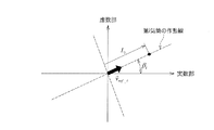
以上のようにして得られた周波数特性をフーリエ級数に展開し、その特性を複素平面上にプロットすると、前述した各場合(1気筒のみでの燃料噴射量を他の3気筒それぞれでの燃料噴射量と異なるものとした場合、燃焼行程が連続する2気筒それぞれでの燃料噴射量を他の2気筒それぞれでの燃料噴射量と異なるものとした場合、燃焼行程が連続しない2気筒それぞれでの燃料噴射量を他の2気筒それぞれでの燃料噴射量と異なるものとした場合)それぞれに特有の作動点が現れる。 The frequency characteristics obtained as described above are developed into a Fourier series, and the characteristics are plotted on a complex plane. In each case described above (the fuel injection amount of only one cylinder is reduced by the fuel injection amount of each of the other three cylinders) When the fuel injection amount is different from the fuel injection amount in each of the two cylinders in which the combustion stroke is continuous, the fuel injection amount in each of the two cylinders in which the combustion stroke is not continuous is different from the fuel injection amount in each of the other two cylinders. When the injection amount is different from the fuel injection amount in each of the other two cylinders), a unique operating point appears for each.
図4は、前記周波数F1の周波数特性をフーリエ級数に展開し複素平面上にプロットした作動点を示している。全ての気筒での燃料噴射量が同一である場合の作動点は、この複素平面上の原点に位置することになる(図4における「●」を参照)。 FIG. 4 shows an operating point where the frequency characteristic of the frequency F1 is expanded into a Fourier series and plotted on a complex plane. The operating point when the fuel injection amount is the same in all cylinders is located at the origin on this complex plane (see “●” in FIG. 4).
これに対し、1気筒のみでの燃料噴射量が他の3気筒それぞれでの燃料噴射量と異なっている場合には、作動点は複素平面上の原点には位置せず、燃料噴射量に乖離が生じている気筒、および、その乖離量に応じた位置となる。 On the other hand, when the fuel injection amount of only one cylinder is different from the fuel injection amount of each of the other three cylinders, the operating point is not located at the origin on the complex plane, but deviates from the fuel injection amount. Is a position corresponding to the cylinder in which is generated and the amount of deviation.
図4の「○」は、1気筒のみでの燃料噴射量が他の3気筒それぞれでの燃料噴射量と異なっている場合であって、第1番気筒♯1での燃料噴射量が他の3気筒それぞれでの燃料噴射量に対して少なくなっている場合の作動点を表している。また、この作動点における原点からの距離Lは燃料噴射量の乖離量(第1番気筒♯1での燃料噴射量と他の3気筒それぞれでの燃料噴射量との乖離量)を表している。なお、第4番気筒♯4での燃料噴射量が他の3気筒それぞれでの燃料噴射量に対して多くなっている場合にも同様の作動点として現れる。以下の説明では、本発明の技術の理解を容易にするために、特定の気筒における燃料噴射量が他の気筒における燃料噴射量よりも少なくなっている場合を例に挙げて説明する。
4 indicates that the fuel injection amount of only one cylinder is different from the fuel injection amount of each of the other three cylinders, and that the fuel injection amount of the
図4に示すように、第3番気筒♯3での燃料噴射量が他の3気筒それぞれでの燃料噴射量に対して多くなっている場合または第2番気筒♯2での燃料噴射量が他の3気筒それぞれでの燃料噴射量に対して少なくなっている場合には、作動点は複素平面の第1象限において破線で示す作動線上に現れる。また、第1番気筒♯1での燃料噴射量が他の3気筒それぞれでの燃料噴射量に対して多くなっている場合または第4番気筒♯4での燃料噴射量が他の3気筒それぞれでの燃料噴射量に対して少なくなっている場合には、作動点は複素平面の第2象限において破線で示す作動線上に現れる。また、第2番気筒♯2での燃料噴射量が他の3気筒それぞれでの燃料噴射量に対して多くなっている場合または第3番気筒♯3での燃料噴射量が他の3気筒それぞれでの燃料噴射量に対して少なくなっている場合には、作動点は複素平面の第3象限において破線で示す作動線上に現れる。さらに、図4の「○」に示すように、第4番気筒♯4での燃料噴射量が他の3気筒それぞれでの燃料噴射量に対して多くなっている場合または第1番気筒♯1での燃料噴射量が他の3気筒それぞれでの燃料噴射量に対して少なくなっている場合には、作動点は複素平面の第4象限において破線で示す作動線上に現れる。このため、原点から作動点に向かうベクトルにおいて、このベクトルが複素平面の座標軸(例えば実数部の座標軸)との成す角度(図4における角度β)によって作動点の象限が特定されるので、この角度βによって燃料噴射量に乖離が生じている気筒(燃料噴射量が他の3気筒それぞれでの燃料噴射量と異なっている一つの気筒)を、ある程度絞り込む(2気筒に絞り込む)ことができる。また、このベクトルの長さ(図4における長さL)によって燃料噴射量の乖離量(1気筒と他の3気筒それぞれとの燃料噴射量の乖離量)を求めることが可能となる。つまり、前記ベクトルにおける複素平面の座標軸との成す角度に基づいて、燃料の燃焼状態が他の気筒とは異なっている気筒を特定し、ベクトル長さに基づいて、この特定された気筒における燃料の燃焼に関連する状態量(本実施形態では燃料噴射量)と他の気筒における当該状態量(燃料噴射量)との偏差を特定することが可能となっている(本発明でいう燃焼状態診断部の機能)。
As shown in FIG. 4, when the fuel injection amount in the
なお、前記角度βは機関回転速度に応じて変化する。このため、作動点が存在する象限の位置と、燃料噴射量に乖離が生じている気筒との関係が適切に得られるように、予め実験などによって機関回転速度に応じた角度補正量を求めておき、この角度補正量だけベクトルの向き(各作動線の傾き)を補正しておくことが好ましい。例えば、本実施形態の場合にあっては、機関回転速度が高いほどベクトルの向きは図4における時計回り方向に移行することになる。 The angle β changes according to the engine speed. Therefore, in order to appropriately obtain the relationship between the position of the quadrant where the operating point is present and the cylinder in which the fuel injection amount is deviated, the angle correction amount according to the engine speed is determined in advance by experiments or the like. It is preferable that the direction of the vector (the inclination of each operation line) is corrected by this angle correction amount. For example, in the case of the present embodiment, the direction of the vector shifts clockwise in FIG. 4 as the engine speed increases.
図5は、燃焼行程が連続する2気筒それぞれでの燃料噴射量を他の2気筒それぞれでの燃料噴射量と異なるものとした場合であって、作動点「□」は、第1番気筒♯1での燃料噴射量および第3番気筒♯3での燃料噴射量が他の2気筒それぞれでの燃料噴射量に対して少なくなっている場合であり、且つ第1番気筒♯1での燃料噴射量と第3番気筒♯3での燃料噴射量とが略同一である(第1番気筒♯1での燃料噴射量の減少量と第3番気筒♯3での燃料噴射量の減少量とが略同一である)場合の作動点を表している。この場合、作動点「□」は何れの作動線上にも位置しないため、原点からこの作動点「□」に向かうベクトルを、第3象限側のベクトル(第3象限における作動線上のベクトルであって、原点から作動点「◇」に向かうベクトル)と第4象限側のベクトル(第4象限における作動線上のベクトルであって、原点から作動点「○」に向かうベクトル)とに分解する。第3象限側に分解されたベクトルは、第3番気筒♯3での燃料噴射量が、第2番気筒♯2および第4番気筒♯4での燃料噴射量に対して少なくなっていることを表しており、このベクトルの長さは、第3番気筒♯3での燃料噴射量と、第2番気筒♯2および第4番気筒♯4での燃料噴射量との乖離量に相当する。同様に、第4象限側に分解されたベクトルは、第1番気筒♯1での燃料噴射量が、第2番気筒♯2および第4番気筒♯4での燃料噴射量に対して少なくなっていることを表しており、このベクトルの長さは、第1番気筒♯1での燃料噴射量と、第2番気筒♯2および第4番気筒♯4での燃料噴射量との乖離量に相当する。
FIG. 5 shows a case where the fuel injection amount in each of the two cylinders whose combustion strokes are continuous is different from the fuel injection amount in each of the other two cylinders. 1 and the fuel injection amount in the
つまり、図5における角度β1が、第3番気筒♯3での燃料噴射量が第2番気筒♯2および第4番気筒♯4での燃料噴射量に対して少なくなっていることを表しており、角度β2が、第1番気筒♯1での燃料噴射量が第2番気筒♯2および第4番気筒♯4での燃料噴射量に対して少なくなっていることを表している。そして、第1番気筒♯1での燃料噴射量の減少量と第3番気筒♯3での燃料噴射量の減少量とが略同一であるため、原点から作動点「□」に向かうベクトルの角度βは、これら角度β1および角度β2の中間の角度となる。このため、第3番気筒♯3での燃料噴射量と第1番気筒♯1での燃料噴射量とが互いに異なっている場合には、原点から作動点「□」に向かうベクトルの角度βも、それに応じて異なることになる。
That is, the angle β1 in FIG. 5 indicates that the fuel injection amount in the
図5における作動点「△」は、第1番気筒♯1での燃料噴射量の減少量(第2番気筒♯2および第4番気筒♯4での燃料噴射量に対する乖離量)と第3番気筒♯3での燃料噴射量の減少量(同じく第2番気筒♯2および第4番気筒♯4での燃料噴射量に対する乖離量)との比を2:3とした場合のものであり、原点から作動点「△」に向かうベクトルの角度は、この比に対応したものとなっている。また、このベクトルを各作動線上のベクトルに分解することで、第1番気筒♯1および第3番気筒♯3それぞれの乖離量(第2番気筒♯2および第4番気筒♯4での燃料噴射量に対する乖離量)を算出することができる。
The operating point “△” in FIG. 5 is the decrease amount of the fuel injection amount in the first cylinder # 1 (the deviation amount from the fuel injection amount in the
同様に、図5における作動点「▲」は、第1番気筒♯1での燃料噴射量の減少量と第3番気筒♯3での燃料噴射量の減少量との比を5:2とした場合のものであり、原点から作動点「▲」に向かうベクトルの角度は、この比に対応したものとなっている。この場合も、このベクトルを各作動線上のベクトルに分解することで、第1番気筒♯1および第3番気筒♯3それぞれの乖離量(第2番気筒♯2および第4番気筒♯4での燃料噴射量に対する乖離量)を算出することができる。
Similarly, the operating point “▲” in FIG. 5 indicates that the ratio between the amount of decrease in the fuel injection amount in the
このように、燃焼行程が連続する2気筒それぞれでの燃料噴射量を他の2気筒それぞれでの燃料噴射量と異なるものとした場合には、F1の複素平面における作動角βが両気筒での燃料噴射量の比を表し、ベクトル長さが噴射量の乖離量を表している。 Thus, when the fuel injection amount in each of the two cylinders whose combustion strokes are continuous is different from the fuel injection amount in each of the other two cylinders, the operating angle β in the complex plane of F1 is The ratio of the fuel injection amount is indicated, and the vector length indicates the deviation amount of the injection amount.
図6は、燃焼行程が連続しない2気筒それぞれでの燃料噴射量を他の2気筒それぞれでの燃料噴射量と異なるものとした場合であって、作動点「△」は、第1番気筒♯1での燃料噴射量が第2番気筒♯2および第3番気筒♯3での燃料噴射量と異なっており、第4番気筒♯4での燃料噴射量が第2番気筒♯2および第3番気筒♯3での燃料噴射量と異なっている場合を表している。この場合、原点から作動点「△」に向かうベクトルの長さが、第1番気筒♯1での燃料噴射量と第4番気筒♯4での燃料噴射量との偏差に相当することになる。具体的に、第1番気筒♯1での燃料噴射量および第4番気筒♯4での燃料噴射量が共に第2番気筒♯2および第3番気筒♯3での燃料噴射量よりも少なくなっている場合において、第1番気筒♯1での燃料噴射量が第4番気筒♯4での燃料噴射量よりも少ない場合(第1番気筒♯1での燃料噴射減少量が多い場合)には、作動点は第4象限に現れる(作動点「△」を参照)。そして、第1番気筒♯1での燃料噴射量と第4番気筒♯4での燃料噴射量との偏差によって作動点の位置は作動線上で異なった位置となる。一方、第1番気筒♯1での燃料噴射量および第4番気筒♯4での燃料噴射量が共に第2番気筒♯2および第3番気筒♯3での燃料噴射量よりも少なくなっている場合において、第4番気筒♯4での燃料噴射量が第1番気筒♯1での燃料噴射量よりも少ない場合(第4番気筒♯4での燃料噴射減少量が多い場合)には、作動点は第2象限に現れる(作動点「□」を参照)。そして、第1番気筒♯1での燃料噴射量と第4番気筒♯4での燃料噴射量との偏差によって作動点の位置は作動線上で異なった位置となる。
FIG. 6 shows a case where the fuel injection amount in each of the two cylinders whose combustion strokes are not continuous is different from the fuel injection amount in each of the other two cylinders, and the operating point “△” is the first cylinder ♯ 1 is different from the fuel injection amount in the
つまり、図6において原点から作動点「△」に向かうベクトルの角度β(実数部の座標軸からの角度)が、第1番気筒♯1での燃料噴射量が第2番気筒♯2および第3番気筒♯3での燃料噴射量と異なっており、第4番気筒♯4での燃料噴射量が第2番気筒♯2および第3番気筒♯3での燃料噴射量と異なっていることを表しており、このベクトル長さが、第1番気筒♯1での燃料噴射量と第4番気筒♯4での燃料噴射量との偏差を表している。この図6における作動点「△」は、第1番気筒♯1での燃料噴射量の減少量と第4番気筒♯4での燃料噴射量の減少量との比を5:1とした場合のものである。
That is, in FIG. 6, the angle β of the vector from the origin to the operating point “実” (the angle from the coordinate axis of the real part) is determined by the fact that the fuel injection amount in the
また、図6における作動点「□」は、第1番気筒♯1での燃料噴射量の減少量と第4番気筒♯4での燃料噴射量の減少量との比を3:5とした場合のものである。
The operating point “□” in FIG. 6 is a ratio of the fuel injection amount decrease amount in the
このように、燃焼行程が連続しない2気筒それぞれでの燃料噴射量を他の2気筒それぞれでの燃料噴射量と異なるものとした場合には、複素平面における作動角βが各気筒を特定し、ベクトル長さが各気筒での噴射量の偏差を表している。 Thus, when the fuel injection amount in each of the two cylinders whose combustion strokes are not continuous is different from the fuel injection amount in each of the other two cylinders, the operating angle β in the complex plane specifies each cylinder, The vector length indicates the deviation of the injection amount in each cylinder.
なお、このように作動点が作動線上に位置している場合、この作動点の位置のみでは、1気筒のみでの燃料噴射量が他の3気筒それぞれでの燃料噴射量と異なっているのか(図4を参照)、燃焼行程が連続しない2気筒それぞれでの燃料噴射量が他の2気筒それぞれでの燃料噴射量と異なっているのか(図6を参照)を判別することはできないが、この両者では、図2および図3で示したように、周波数F1,F2の大小関係が逆転している。つまり、1気筒のみでの燃料噴射量が他の3気筒それぞれでの燃料噴射量と異なっている場合には、F1の大きさがF2の大きさに比べて大きくなる。これに対し、燃焼行程が連続しない2気筒それぞれでの燃料噴射量が他の2気筒それぞれでの燃料噴射量と異なっている場合には、F2の大きさがF1の大きさに比べて大きくなる。このように、作動点の位置および周波数F1,F2の大きさを比較することで、前記判別(1気筒のみでの燃料噴射量が他の3気筒それぞれでの燃料噴射量と異なっているのか、燃焼行程が連続しない2気筒それぞれでの燃料噴射量が他の2気筒それぞれでの燃料噴射量と異なっているのかの判別)が可能である。 When the operating point is located on the operating line, is the fuel injection amount of only one cylinder different from the fuel injection amount of each of the other three cylinders only at the position of the operating point? It is not possible to determine whether the fuel injection amount in each of the two cylinders whose combustion strokes are not continuous is different from the fuel injection amount in each of the other two cylinders (see FIG. 6). In both cases, as shown in FIGS. 2 and 3, the magnitude relationship between the frequencies F1 and F2 is reversed. That is, when the fuel injection amount of only one cylinder is different from the fuel injection amount of each of the other three cylinders, the size of F1 is larger than the size of F2. On the other hand, when the fuel injection amount in each of the two cylinders whose combustion strokes are not continuous is different from the fuel injection amount in each of the other two cylinders, the size of F2 becomes larger than the size of F1. . As described above, by comparing the position of the operating point and the magnitudes of the frequencies F1 and F2, the above-described determination (whether the fuel injection amount in only one cylinder is different from the fuel injection amount in each of the other three cylinders, It is possible to determine whether the fuel injection amount in each of the two cylinders whose combustion strokes are not continuous is different from the fuel injection amount in each of the other two cylinders).
なお、本実施形態では4気筒エンジンを例に挙げているため、燃焼行程が連続しない2気筒は、ピストンの往復移動の位相が同一であって且つ燃焼行程がクランク角度で360°の位相差を有したものとなっている。他の気筒数(例えば6気筒など)のエンジンにあっても、本発明でいう「燃焼行程が連続しない複数の気筒」とは、ピストンの往復移動の位相が同一であって且つ燃焼行程がクランク角度で互いに異なる位相のものである。一例として、6気筒エンジンにおいて、燃焼行程の順序が第1番気筒♯1→第5番気筒♯5→第3番気筒♯3→第6番気筒♯6→第2番気筒♯2→第4番気筒♯4であった場合には、例えば第1番気筒♯1と第6番気筒♯6とが、ここでいう燃焼行程が連続しない2気筒となる。
In the present embodiment, a four-cylinder engine is used as an example. Therefore, in the two cylinders in which the combustion strokes are not continuous, the phase of the reciprocating movement of the piston is the same and the combustion stroke has a phase difference of 360 ° in crank angle. It is what you have. Even in an engine having a different number of cylinders (for example, six cylinders), the term "a plurality of cylinders in which the combustion stroke is not continuous" in the present invention means that the phase of the reciprocating movement of the piston is the same and the combustion stroke is the crank stroke. The phases are different from each other in angle. As an example, in a 6-cylinder engine, the order of the combustion strokes is as follows: the
<総燃料噴射量の診断の原理>
また、本実施形態における燃焼状態診断としては、前述した各気筒♯1〜♯4間での燃料噴射量のバラツキの診断だけでなく、各気筒♯1〜♯4それぞれの1サイクルにおいてインジェクタ52,52,…から噴射された燃料の噴射総量(以下、総燃料噴射量という)の診断も行うようにしている。以下、この総燃料噴射量の診断の原理について説明する。
<Principle of diagnosis of total fuel injection amount>
The diagnosis of the combustion state in the present embodiment includes not only the diagnosis of the variation of the fuel injection amount among the
前記周波数F4は燃焼周波数fcmbに一致しているため前記総燃料噴射量と強い相関がある。このため、この周波数F4に基づいて前記総燃料噴射量を求めることが可能である。 Since the frequency F4 matches the combustion frequency f cmb , there is a strong correlation with the total fuel injection amount. Therefore, the total fuel injection amount can be obtained based on the frequency F4.
この総燃料噴射量は、図7に示すマップ(総燃料噴射量算出マップ)に従って求められる。この総燃料噴射量算出マップは、周波数F4の強度および機関回転速度をパラメータとして総燃料噴射量Qallを求めるものである。同一機関回転速度であっても周波数F4の強度が高いほど総燃料噴射量Qallは大きな値として求められ、周波数F4の強度が同一であっても機関回転速度が低いほど総燃料噴射量Qallは大きな値として求められることになる。このマップは、予め実験やシミュレーションによって作成されて前記エンジンECU100のROMに記憶されている。
The total fuel injection amount is obtained according to a map shown in FIG. 7 (total fuel injection amount calculation map). This total fuel injection amount calculation map is for obtaining the total fuel injection amount Q all using the intensity of the frequency F4 and the engine speed as parameters. Even if the engine speed is the same, the higher the intensity of the frequency F4 is, the larger the total fuel injection amount Q all is obtained. Even if the intensity of the frequency F4 is the same, the lower the engine speed is, the higher the total fuel injection amount Q all is. Will be determined as a large value. This map is created in advance by experiments and simulations and stored in the ROM of the
このように総燃料噴射量の診断は、前記エンジンECU100によって行われる。このため、このエンジンECU100における、前記総燃料噴射量の診断(総燃料噴射量に基づいた各気筒での燃料の燃焼状態の診断)を実行する機能部分が本発明でいう燃焼状態診断部(過給機回転速度検出手段から出力された信号の周波数特性、および、内燃機関回転速度検出手段から出力された信号に基づいて算出された機関回転速度をパラメータとして、内燃機関の1サイクル中に各気筒に供給された総燃料供給量を演算することで各気筒での燃料の燃焼状態を診断する燃焼状態診断部)に相当する。
Thus, the diagnosis of the total fuel injection amount is performed by the
以上が本実施形態に係る燃焼状態診断の概要である。 The outline of the combustion state diagnosis according to the present embodiment has been described above.
−燃焼状態診断−
次に、前述した診断手法の原理を用いて実際に燃焼状態を診断し、その診断の結果に応じて燃料噴射量を補正する場合の手順について説明する。
-Combustion state diagnosis-
Next, a procedure for actually diagnosing the combustion state using the principle of the above-described diagnosis method and correcting the fuel injection amount according to the result of the diagnosis will be described.
<総燃料噴射量の診断動作および補正動作>
先ず、前記総燃料噴射量の診断動作および補正動作について図8のフローチャートに沿って説明する。このフローチャートは、エンジン1のスタートスイッチがONされた後、所定時間毎に繰り返される。
<Diagnosis operation and correction operation of total fuel injection amount>
First, the diagnosis operation and the correction operation of the total fuel injection amount will be described with reference to the flowchart of FIG. This flowchart is repeated every predetermined time after the start switch of the
先ず、ステップST1において、ターボチャージャ40の瞬時回転速度を取得する。具体的には、前記ターボ回転速度センサ104から出力された信号(サイン波または矩形波)をF/V変換器110によって周波数変換し、これにより、ターボチャージャ40の瞬時回転速度を取得する。
First, in step ST1, the instantaneous rotation speed of the
その後、ステップST2において、前記式(5)によって算出されている周波数F4を取得する。 Thereafter, in step ST2, the frequency F4 calculated by the above equation (5) is obtained.
周波数F4を取得した後、ステップST3において、前記図7の総燃料噴射量算出マップを用いて総燃料噴射量Qallを算出する。具体的には、前記ターボチャージャ40の瞬時回転速度の情報をエンジンECU100に送信し、周波数分析データのうち、F4データを基に、前記総燃料噴射量算出マップを用いて総燃料噴射量Qallを算出する。
After obtaining the frequency F4, in step ST3, the total fuel injection amount Q all is calculated using the total fuel injection amount calculation map of FIG. Specifically, information on the instantaneous rotational speed of the
次に、ステップST4において、以下の式(6)により、この総燃料噴射量Qallに基づき、各気筒♯1〜♯4それぞれに均等に燃料が噴射されていると仮定した場合の各インジェクタ52,52,…からの燃料噴射量(平均燃料噴射量)Qaveを算出する。
Next, in step ST4, each
その後、ステップST5において、燃料噴射量の乖離量ΔQtgtを算出する。前記エンジンECU100は、前記出力操作部材101の操作量に応じて、インジェクタ52,52,…からの燃料噴射量として目標噴射量Qtgtを演算している。このステップST5では、前記式(6)で算出された平均燃料噴射量Qaveから前記目標噴射量Qtgtを減算することでこの両者の乖離量ΔQtgtを算出する(式(7))。
After that, in step ST5, a deviation amount ΔQ tgt of the fuel injection amount is calculated. The
ステップST6では、この乖離量ΔQtgtの絶対値が所定の閾値Qthを超えているか否かを判定する。この閾値Qthは、インジェクタ52からの燃料噴射量が過少になっている等の燃料供給装置50の異常の有無を判断するための値であって、予め実験やシミュレーションによって設定されている。
In step ST6, determines whether or not the absolute value of the deviation amount Delta] Q tgt exceeds the predetermined threshold Q th. The threshold value Qth is a value for determining whether or not there is an abnormality in the
乖離量ΔQtgtの絶対値が前記閾値Qthを超えており、ステップST6でYES判定された場合には、ステップST7に移り、燃料供給装置50の異常、若しくは、燃料性状の著しい変化により失火が発生しているとして、ユーザに警告を発する。例えば、図示しない操作パネル上に警告表示を行ったり、音声による警告を発したりする。また、エンジンECU100のRAMに異常発生情報の書き込みを行う。
The absolute value of the deviation amount Delta] Q tgt and exceeds the threshold value Q th, when it is determined YES at step ST6, the procedure proceeds to step ST7, the abnormality of the
一方、乖離量ΔQtgtの絶対値が前記閾値Qthを超えておらず、ステップST6でNO判定された場合には、ステップST8に移り、各インジェクタ52,52,…の燃料噴射量の補正を行う。つまり、前記乖離量ΔQtgtが正の値であった場合には、各気筒♯1〜♯4それぞれにおけるインジェクタ52,52,…からの燃料噴射量を乖離量ΔQtgtだけ減量する補正を行う。一方、乖離量ΔQtgtが負の値であった場合には、各気筒♯1〜♯4それぞれにおけるインジェクタ52,52,…からの燃料噴射量を乖離量ΔQtgtだけ増量する補正を行う。これら燃料噴射量の補正は、例えばインジェクタ52,52,…の開弁時間を変更する(増量補正する場合には、その増量補正量に応じて開弁時間を長くし、減量補正する場合には、その減量補正量に応じて開弁時間を短くする)ことによって行われる。
On the other hand, the divergence amount absolute value of Delta] Q tgt does not exceed the threshold value Q th, when it is determined NO at step ST6, the procedure proceeds to step ST8, the
このようにして各インジェクタ52,52,…の燃料噴射量の補正が行われると、各気筒♯1〜♯4それぞれにおける燃料噴射量は、以下の式(8)におけるQtgt_corに収束していくことになる。
When the fuel injection amount of each of the
以上の動作が繰り返されることにより、総燃料噴射量Qallが、エンジン1に要求される出力を得るための総燃料噴射量(目標噴射量Qtgtを気筒数倍した目標総燃料噴射量)に収束していくことになる。
By repeating the above operation, the total fuel injection amount Q all becomes the total fuel injection amount (the target total fuel injection amount obtained by multiplying the target injection amount Q tgt by the number of cylinders) for obtaining the output required for the
このような総燃料噴射量の補正動作が行われるため、前記ステップST4〜ST8の動作が本発明でいう燃料供給量補正部による動作(多気筒内燃機関の1サイクル中に各気筒に供給された総燃料供給量を気筒数で除算して平均燃料供給量を求め、要求出力に応じて決定された各気筒での目標燃料供給量と平均燃料供給量との偏差分だけ各気筒毎に燃料供給量を補正する動作)に相当する。 Since such a correction operation of the total fuel injection amount is performed, the operations of steps ST4 to ST8 are performed by the fuel supply amount correction unit according to the present invention (the operation performed by each cylinder during one cycle of the multi-cylinder internal combustion engine). The average fuel supply is calculated by dividing the total fuel supply by the number of cylinders, and fuel is supplied to each cylinder by the deviation between the target fuel supply and the average fuel supply in each cylinder determined according to the required output. Operation to correct the amount).
なお、このような総燃料噴射量Qallの診断動作および補正動作は、機関負荷が上限値に達した際に行うことが好ましい。これは、部分負荷域において総燃料噴射量Qallを補正した場合、エンジン1の調速性が悪化する可能性があるためである。
It is preferable that such a diagnosis operation and a correction operation of the total fuel injection amount Q all be performed when the engine load reaches the upper limit. This is because if the total fuel injection amount Q all is corrected in the partial load range, the speed controllability of the
以上が、総燃料噴射量の診断動作および補正動作である。 The above is the diagnosis operation and the correction operation of the total fuel injection amount.
<燃料噴射量のバラツキの診断動作および解消動作>
次に、各インジェクタ52,52,…の燃料噴射量のバラツキの診断動作およびバラツキの解消動作について図9のフローチャートに沿って説明する。このフローチャートも、エンジン1のスタートスイッチがONされた後、所定時間毎に繰り返される。
<Diagnosis operation and elimination operation of fuel injection amount variation>
Next, the operation of diagnosing the variation in the fuel injection amount of each
先ず、ステップST11では、前記図8で示したフローチャートのステップST1の場合と同様にターボチャージャ40の瞬時回転速度を取得する。
First, in step ST11, the instantaneous rotation speed of the
その後、ステップST12に移り、前記式(2)および式(3)によってそれぞれ算出されている周波数F1,F2を取得する。 Thereafter, the process proceeds to step ST12, where the frequencies F1 and F2 calculated by the above equations (2) and (3) are obtained.
周波数F1,F2を取得した後、ステップST13に移り、各インジェクタ52,52,…それぞれの燃料噴射量が互いに略同一であるか否かを判定する。この判定動作として具体的には、前記周波数F1,F2の強度が共に略「0」となっているか否かを判定する。前述したように、全てのインジェクタ52,52,…の燃料噴射量が同一である場合には、周波数F1,F2の強度は共に略「0」となるため(図2および図3を参照)、これらの強度を認識することによって、各インジェクタ52,52,…それぞれの燃料噴射量が互いに略同一であるか否かを判定することができる。
After acquiring the frequencies F1 and F2, the process proceeds to step ST13, and it is determined whether or not the fuel injection amounts of the
また、別の判定手法として、前記周波数F1,F2それぞれの周波数特性をフーリエ級数に展開し複素平面上にプロットした作動点が複素平面上の原点に位置しているか否かを判定するようにしてもよい。前述したように、全てのインジェクタ52,52,…の燃料噴射量が略同一である場合には、その作動点は複素平面上の原点に位置することになるので、この作動点が複素平面上の原点に位置しているか否かを認識することによって、各インジェクタ52,52,…それぞれの燃料噴射量が互いに略同一であるか否かを判定することができる。
As another determination method, it is determined whether or not the operating point plotted on a complex plane by expanding the frequency characteristics of the frequencies F1 and F2 into a Fourier series is located at the origin on the complex plane. Is also good. As described above, when the fuel injection amounts of all the
各インジェクタ52,52,…それぞれの燃料噴射量が互いに同一であり、ステップST13でYES判定された場合には、燃料噴射量のバラツキを解消するための補正動作は必要ないとして、そのままリターンされる。
If the fuel injection amounts of the
一方、各インジェクタ52,52,…それぞれの燃料噴射量が互いに略同一ではなく、ステップST13でNO判定された場合にはステップST14に移り、周波数F1,F2それぞれの強度の比較を行う。具体的には、周波数F1の強度が周波数F2の強度よりも高いか否かを判定する。この判定は、「1気筒のみでの燃料噴射量が他の3気筒それぞれでの燃料噴射量と異なっている、または、燃焼行程が連続する2気筒それぞれでの燃料噴射量が他の2気筒それぞれでの燃料噴射量と異なっている」状況であるのか、または、「燃焼行程が連続しない2気筒それぞれでの燃料噴射量が他の2気筒それぞれでの燃料噴射量と異なっている」状況であるのかを判別するためのものである。前述したように、1気筒のみでの燃料噴射量が他の3気筒それぞれでの燃料噴射量と異なっている場合や、燃焼行程が連続する2気筒それぞれでの燃料噴射量が他の2気筒それぞれでの燃料噴射量と異なっている場合には、ターボチャージャ40の回転速度の変動は、F1に大きく現れ、F1の大きさはF2の大きさに比べて大幅に大きくなる。これに対し、燃焼行程が連続しない2気筒それぞれでの燃料噴射量が他の2気筒それぞれでの燃料噴射量と異なっている場合には、ターボチャージャ40の回転速度の変動は、F1に比べてF2の方が強くなる。
On the other hand, when the fuel injection amounts of the
このため、周波数F1の強度が周波数F2の強度よりも高くなっており、ステップST14でYES判定された場合には、1気筒のみでの燃料噴射量が他の3気筒それぞれでの燃料噴射量と異なっている、または、燃焼行程が連続する2気筒それぞれでの燃料噴射量が他の2気筒それぞれでの燃料噴射量と異なっている状況であると判断できる。一方、周波数F2の強度が周波数F1の強度よりも高くなっており、ステップST14でNO判定された場合には、燃焼行程が連続しない2気筒それぞれでの燃料噴射量が他の2気筒それぞれでの燃料噴射量と異なっている状況であると判断できる。 For this reason, the intensity of the frequency F1 is higher than the intensity of the frequency F2, and if YES is determined in step ST14, the fuel injection amount of only one cylinder becomes smaller than the fuel injection amount of each of the other three cylinders. It can be determined that the situation is different or the fuel injection amount in each of the two cylinders whose combustion strokes are continuous is different from the fuel injection amount in each of the other two cylinders. On the other hand, when the intensity of the frequency F2 is higher than the intensity of the frequency F1 and the determination of NO is made in step ST14, the fuel injection amount in each of the two cylinders whose combustion strokes are not continuous is reduced in each of the other two cylinders. It can be determined that the situation is different from the fuel injection amount.
ステップST14でYES判定された場合には、ステップST15に移り、後述する診断方法1によって、各インジェクタ52,52,…の燃料噴射量のバラツキの診断を行う。この診断方法1の具体的な手法については後述する。一方、ステップST14でNO判定された場合には、ステップST16に移り、後述する診断方法2によって、各インジェクタ52,52,…の燃料噴射量のバラツキの診断を行う。この診断方法2の具体的な手法についても後述する。
If YES is determined in step ST14, the process proceeds to step ST15, and a diagnosis of a variation in the fuel injection amount of each
以下、各診断方法の具体的な手法について説明する。 Hereinafter, a specific method of each diagnostic method will be described.
何れの診断方法においても、先ず、事前にエンジン回転速度に対する各気筒♯1〜♯4それぞれにおける燃料噴射量変更時の作動基底ベクトルを実験または解析によって求めておく。この作動基底ベクトルは、一つの気筒におけるインジェクタ52の燃料噴射量を予め設定された単位噴射量だけ変化させた場合において、その燃料噴射量を変化させた気筒および変化量に対応するベクトル角度およびベクトル長さを前記複素平面上に表したものである。図10は、第2番気筒♯2での燃料噴射量を単位噴射量だけ減量させた場合の作動基底ベクトルv→ ref_iを示している。つまり、この作動基底ベクトルv→ ref_iは、第i気筒(図10では例えば第2番気筒♯2)での燃料噴射量を変更した際の極座標上の原点と作動点とを結ぶベクトルを単位噴射量当たりに整理したものとなっている。このため、実際の作動点が図10における「●」の位置であった場合には、前記作動基底ベクトルv→ ref_iの長さをLi倍したベクトルが、この作動点「●」を現すベクトル(原点から作動点「●」に向かうベクトル)となる。つまり、前記単位噴射量のLi倍の燃料噴射量だけ第i気筒では燃料噴射量がずれていることになる。
In any of the diagnosis methods, first, an operating base vector at the time of changing the fuel injection amount in each of the
以下、前記診断方法1の具体的な手法について説明する。前述した如く、診断方法1は、周波数F1の強度が周波数F2の強度よりも高くなっており、「1気筒のみでの燃料噴射量が他の3気筒それぞれでの燃料噴射量と異なっている、または、燃焼行程が連続する2気筒それぞれでの燃料噴射量が他の2気筒それぞれでの燃料噴射量と異なっている」状況であると判定された場合に実行される。
Hereinafter, a specific method of the
この診断方法1では、先ず、前記周波数F1成分を抽出し、複素平面上に実測の作動点(以下、実測作動点という場合もある)をプロットする。図11は実測作動点が座標(βact,Lact)にプロットされた場合を示している。
In the
そして、複素平面上の原点から実測作動点(βact,Lact)に向かう実測作動点ベクトルV→ actを求め、この実測作動点ベクトルV→ actを、この実測作動点ベクトルV→ actを挟む各作動線上に分解する。つまり、2つの気筒i,jを対象とする作動点ベクトルV→ act_i,V→ act_jに分解する。この分解して得られた2方向のベクトルV→ act_i,V→ act_jのスカラー量を求め、事前に求めた相関式を利用して各気筒i,jでの燃料噴射量のずれ量(他の気筒における燃料噴射量からのずれ量)ΔQi,ΔQjを算出する。 Then, the measured operating point from the origin of the complex plane (β act, L act) the actual working point vector V → act towards seeking, the actual working point vector V → act, sandwiching the measured working point vector V → act Disassemble on each working line. That is, the operation point vectors V → act_i and V → act_j for the two cylinders i and j are decomposed. A scalar amount of the two-directional vector V → act_i , V → act_j obtained by the decomposition is obtained, and a deviation amount of the fuel injection amount in each of the cylinders i and j is calculated using a correlation expression obtained in advance. shift amount from the fuel injection amount in the cylinder) Delta] Q i, to calculate the Delta] Q j.
なお、前記気筒iを対象とする作動点ベクトルV→ act_i、作動基底ベクトルv→ ref_i、スカラー量Liとの間には以下の式(9)の関係があり、この式(9)からスカラー量Liを算出することが可能である。 Incidentally, the working point vector V → act_i intended for the cylinder i, actuating basis vectors v → ref_i, have the following relationship of equation (9) between the scalar quantity L i, scalar from the equation (9) it is possible to calculate the amount L i.
以上の診断方法1の手法を図11を用いて具体的に説明する。
The method of the above
図11に示すように、実測作動点ベクトルがV→ actであった場合、この実測作動点ベクトルV→ actを、気筒i,jを対象とする作動点ベクトルV→ act_i,V→ act_jに分解し、これら各ベクトルのV→ act_i,V→ act_jのスカラー量(補正前のスカラー量)を以下の式(10)(11)によって算出する。ここで、Lact_iは第i気筒での燃料噴射量のずれ量に相当するスカラー量である。また、Lact_jは第j気筒での燃料噴射量のずれ量に相当するスカラー量である。また、βref_iは実数部の座標軸からの作動点ベクトルV→ act_iの角度であり、βref_jは実数部の座標軸からの作動点ベクトルV→ act_jの角度である。 As shown in FIG. 11, when the measured operating point vector is V → act , the measured operating point vector V → act is decomposed into operating point vectors V → act_i , V → act_j for cylinders i and j. Then , the scalar amounts (scalar amounts before correction) of V → act_i and V → act_j of these vectors are calculated by the following equations (10) and (11). Here, Lact_i is a scalar amount corresponding to a deviation amount of the fuel injection amount in the i-th cylinder. Lact_j is a scalar amount corresponding to a deviation amount of the fuel injection amount in the j-th cylinder. Also, the beta Ref_i the angle of the working point vector V → act_i from the coordinate axis of the real part, beta Ref_j is the angle of the working point vector V → act_j from the coordinate axis of the real part.
そして、これら燃料噴射量のずれ量を下記の式(12)(13)によって補正することによって第i気筒での燃料噴射量のずれ量ΔQiおよび第j気筒での燃料噴射量のずれ量ΔQjを算出する。 Then, the deviations of the fuel injection amounts are corrected by the following formulas (12) and (13), whereby the deviation ΔQ i of the fuel injection amount in the i-th cylinder and the deviation ΔQ of the fuel injection amount in the j-th cylinder are corrected. j is calculated.
式(12)(13)における係数aは、実験またはシミュレーションによって予め求められたものであって、例えば図12に示すようなスカラー量Lと実際の燃料噴射量のずれ量ΔQとの関係を規定するものである。 The coefficient a in the equations (12) and (13) is obtained in advance by an experiment or a simulation, and defines a relationship between the scalar amount L and the deviation amount ΔQ of the actual fuel injection amount as shown in FIG. 12, for example. Is what you do.
なお、燃料噴射量のずれ量ΔQi,ΔQjの算出にあたっては、前述した式によって行うものに代えて、予め作成されたずれ量算出マップによって抽出するようにしてもよい。さらに、前記係数aは、実験またはシミュレーションに応じ、全気筒で同一の値であってもよいし、各気筒毎に個別の値が設定されていてもよい。 When calculating the deviation amounts ΔQ i and ΔQ j of the fuel injection amount, instead of using the above-described equations, the deviation amounts may be extracted using a deviation amount calculation map created in advance. Further, the coefficient a may be the same value for all cylinders or an individual value may be set for each cylinder according to an experiment or a simulation.
次に、前記診断方法2の具体的な手法について説明する。前述した如く、診断方法2は、周波数F2の強度が周波数F1の強度よりも高くなっており、「燃焼行程が連続しない2気筒それぞれでの燃料噴射量が他の2気筒それぞれでの燃料噴射量と異なっている」状況であると判定された場合に実行される。
Next, a specific method of the
この診断方法2では、先ず、前記周波数F1成分を抽出し、複素平面上に実測作動点をプロットする。図13は作動点が座標(βact,Lact)にプロットされた場合を示している。
In the
F1の複素平面上の作動点から、対象となる2つの気筒を特定する。つまり、作動点が現れている複素平面上の象限によって2つの気筒を特定する。そして、何れかの気筒における燃料噴射量を増量または減量させ(図13に一点鎖線V→1で示すベクトルは第i気筒(第2気筒♯2)を減量させた場合であり、一点鎖線V→2で示すベクトルは第i気筒(第2気筒♯2)を増量させた場合である)、F1成分が「0」となるようにする。つまり、前記作動点が複素平面上の原点に位置するようにする。この場合、当該2つの気筒での燃料噴射量のずれ量は一致したことになる。
From the operating points on the complex plane of F1, two target cylinders are specified. That is, the two cylinders are specified by the quadrant on the complex plane where the operating point appears. Then, the fuel injection amount in any one of the cylinders is increased or decreased (the vector indicated by the one-dot
そして、F2の複素平面上において、作動点と燃料噴射量のずれ量との関係から、2つの気筒のずれ量(2つの気筒それぞれでの燃料噴射量を一致させた状態において、この燃料噴射量と、他の2つの気筒それぞれでの燃料噴射量とのずれ量)を算出する。そして、事前に求めておいた燃料噴射量補正値を考慮して各気筒における燃料噴射量のずれ量を算出する。 Then, on the complex plane of F2, based on the relationship between the operating point and the shift amount of the fuel injection amount, the shift amount of the two cylinders (when the fuel injection amount in each of the two cylinders is matched, this fuel injection amount (A deviation amount from the fuel injection amount in each of the other two cylinders). Then, a deviation amount of the fuel injection amount in each cylinder is calculated in consideration of the fuel injection amount correction value obtained in advance.
以上の診断方法2の手法を図13〜図15を用いて具体的に説明する。
The method of the above
図13に示すように、反位相にある気筒同士の燃料噴射量がずれている場合、どちらの気筒がどの程度ずれているかを特定することは難しい。そのため、事前に、互いに反位相となっている気筒同士(第i気筒と第j気筒)を組み合わせて、双方の燃料噴射量を同量だけ変更した場合のF2の特性を把握する(図15を参照)。 As shown in FIG. 13, when the fuel injection amounts of the cylinders in opposite phases are different, it is difficult to specify which cylinder is different and how much. Therefore, in advance, the characteristics of F2 when the cylinders having opposite phases are combined (i.e., the i-th cylinder and the j-th cylinder) and both fuel injection amounts are changed by the same amount are grasped (see FIG. 15). reference).
この際、燃料噴射量の変化量に対する特性は直線にならない場合が想定されるので(図14を参照)、マップ形式でデータを採取して演算することが望ましい。つまり、事前計測において、燃料噴射量の変化量を増減両方向に複数ステップ採取し、その特性を図15に示すようにプロットしておく。そして、この場合の燃料噴射量のずれ量ΔQijと作動点の座標(βij,Lij)を保管しておく。 At this time, since it is assumed that the characteristic with respect to the change amount of the fuel injection amount does not become a straight line (see FIG. 14), it is desirable to collect and calculate data in a map format. That is, in advance measurement, the amount of change in the fuel injection amount is sampled in a plurality of steps in both directions of increase and decrease, and the characteristics are plotted as shown in FIG. Then, the deviation amount ΔQ ij of the fuel injection amount and the coordinates (β ij , L ij ) of the operating point in this case are stored.
F1の複素平面上に作動点をプロットする場合の動作としては、先ず、エンジン運転時における実測作動点をF1の複素平面上にプロットする。この際、作動点は図10で得られた各気筒の作動線上に位置する。これは、図13に示すように、互いに反位相となっている気筒同士の燃料噴射量がずれている場合は、β方向には変化が生じないためである。仮に第i気筒での燃料噴射量のずれ量と第j気筒での燃料噴射量のずれ量とが同量であった場合には、F1の複素平面上の作動点は原点から動かないことになる。 As an operation for plotting an operating point on the complex plane of F1, first, an actually measured operating point during engine operation is plotted on the complex plane of F1. At this time, the operating point is located on the operating line of each cylinder obtained in FIG. This is because, as shown in FIG. 13, when the fuel injection amounts of the cylinders having opposite phases are shifted from each other, no change occurs in the β direction. If the shift amount of the fuel injection amount in the i-th cylinder is equal to the shift amount of the fuel injection amount in the j-th cylinder, the operating point on the complex plane of F1 does not move from the origin. Become.
燃料噴射量の変更動作としては、F1の複素平面上の作動点が原点と異なっている場合に、第i気筒および第j気筒のうちの何れかの気筒に供給する燃料噴射量を調整することで作動点を原点に導く。仮に第i気筒での燃料噴射量を調整した場合、作動点が原点に到達した際の補正噴射量ΔQi_corを保存しておく。この時点で、対象気筒である第i気筒および第j気筒での燃料噴射量のずれ量は等しくなっている。 The operation of changing the fuel injection amount is to adjust the fuel injection amount supplied to any one of the i-th cylinder and the j-th cylinder when the operating point on the complex plane of F1 is different from the origin. Guides the operating point to the origin. If the fuel injection amount in the i-th cylinder is adjusted, the corrected injection amount ΔQ i_cor when the operating point has reached the origin is stored. At this point, the deviation amounts of the fuel injection amounts in the i-th cylinder and the j-th cylinder, which are the target cylinders, are equal.
各気筒に共通のずれ量の特定にあたっては、F2の複素平面上に作動点をプロットし、その座標(βij_act,Lij_act)と、事前に得ていた燃料噴射量のずれ量の特性データから第i気筒および第j気筒での燃料噴射量のずれ量ΔQijを算出する。 In order to specify the deviation common to each cylinder, the operating point is plotted on the complex plane of F2, and the coordinates (β ij_act , L ij_act ) and the characteristic data of the deviation of the fuel injection amount obtained in advance are used. A deviation amount ΔQ ij of the fuel injection amount between the i-th cylinder and the j-th cylinder is calculated.
第i気筒での燃料噴射量のずれ量ΔQiは以下の式(14)によって算出することが可能である。また、第j気筒での燃料噴射量のずれ量ΔQjは以下の式(15)によって算出することが可能である。 The deviation amount ΔQ i of the fuel injection amount in the i-th cylinder can be calculated by the following equation (14). Further, the deviation amount ΔQ j of the fuel injection amount in the j-th cylinder can be calculated by the following equation (15).
以上が各診断方法である。 The above is each diagnostic method.
図9のフローチャートに戻り、前記診断方法1または前記診断方法2によって第i気筒での燃料噴射量のずれ量ΔQiおよび第j気筒での燃料噴射量のずれ量ΔQjが算出された後、ステップST17に移り、以下の式(16)(17)によって、各気筒における燃料噴射量のバラツキを解消するための各気筒での燃料噴射量Qi_cor,Qj_corを算出する。式(16)は第i気筒での燃料噴射量のずれを解消するための燃料噴射量Qi_corを求める式であり、式(17)は第j気筒での燃料噴射量のずれを解消するための燃料噴射量Qj_corを求める式である。
Returning to the flowchart of FIG. 9, after the shift amount Delta] Q j of the
このようにして各気筒における燃料噴射量を算出した後、ステップST18に移り、この算出した燃料噴射量が得られるようにインジェクタ52の開弁時間を制御して燃料噴射を実行する。
After calculating the fuel injection amount in each cylinder in this way, the process proceeds to step ST18, and the fuel injection is executed by controlling the valve opening time of the
なお、前述したように、本実施形態における燃料噴射量のバラツキの診断では、1気筒のみでの燃料噴射量が他の3気筒それぞれでの燃料噴射量と異なっている場合、ピストンが同位相で往復動し且つ燃焼行程が連続しない2つの気筒(例えば、第1番気筒♯1と第4番気筒♯4)の何れかの燃料噴射量に乖離が生じていると診断することができる。このため、実際の燃料噴射にあっては、前記算出した燃料噴射量で一方の気筒に対する燃料噴射を行い、これによって燃料噴射量のバラツキが解消されない場合には、この一方の気筒に対する燃料噴射を戻し、他方の気筒に対して前記算出した燃料噴射量での燃料噴射を行うことになる。これは2気筒それぞれでの燃料噴射量が他の2気筒それぞれでの燃料噴射量と異なっている場合も同様である。
As described above, in the diagnosis of the variation in the fuel injection amount in the present embodiment, when the fuel injection amount in only one cylinder is different from the fuel injection amount in each of the other three cylinders, the pistons have the same phase. It can be diagnosed that a difference has occurred in any one of the two cylinders (for example, the
このような燃料噴射量のバラツキの解消動作が行われるため、前記ステップST17,ST18の動作が本発明でいうバラツキ解消補正部による動作(各気筒間での燃料の燃焼状態のバラツキを解消するように、各気筒毎に、燃料の燃焼状態を変化させる制御量を補正する動作)に相当する。 Since the operation of eliminating the variation of the fuel injection amount is performed, the operations of steps ST17 and ST18 are performed by the operation of the variation eliminating correction unit according to the present invention (in order to eliminate the variation in the combustion state of the fuel between the cylinders). This corresponds to the operation of correcting the control amount for changing the combustion state of the fuel for each cylinder.
なお、コモンレール式の燃料供給装置50の場合、燃料噴射量は燃料圧力とインジェクタ52のソレノイド等への通電時間によって制御されるため、以下の式(18)(19)によって燃料噴射量のずれを解消するようにしてもよい。
In the case of the common rail type
これら式(18)(19)におけるτはインジェクタ52への通電時間(開弁時間に相当)である。つまり、τiは第i気筒のインジェクタ52に対する現在(補正前)の開弁時間であり、τjは第j気筒のインジェクタ52に対する現在(補正前)の開弁時間である。また、Δτi_corは第i気筒におけるインジェクタ52の開弁時間の補正量であり、Δτj_corは第j気筒におけるインジェクタ52の開弁時間の補正量である。また、τi_corは第i気筒におけるインジェクタ52の補正後の開弁時間であり、τj_corは第j気筒におけるインジェクタ52の補正後の開弁時間である。
In these equations (18) and (19), τ is the time of energizing the injector 52 (corresponding to the valve opening time). That is, τ i is the current (before correction) valve opening time for the
以上の動作が繰り返されることにより、各インジェクタ52,52,…の燃料噴射量のバラツキが解消されることになる。
By repeating the above operation, the variation in the fuel injection amount of each
本実施形態では、前述したように、総燃料噴射量の補正動作および各インジェクタ52,52,…の燃料噴射量のバラツキの解消動作を行うことにより、各気筒♯1〜♯4それぞれにおける燃料噴射量を適正に制御することが可能になる。つまり、各気筒♯1〜♯4それぞれのインジェクタ52,52,…の燃料噴射量をバラツキ無く前記目標噴射量Qtgtに合わせ込むことができる。このため、機関出力の低下の抑制、回転変動の減少、排気エミッションの改善等を図ることができる。
In the present embodiment, as described above, the fuel injection in each of the
(変形例1)
次に、変形例1について説明する。本変形例は、前述した総燃料噴射量の診断動作および燃料噴射量のバラツキの診断動作それぞれの実行許可条件を規定するものである。つまり、実行許可条件が成立した場合に限り、前述した各診断動作を実行するようになっている。
(Modification 1)
Next,
本発明は、各気筒♯1〜♯4に対する燃料噴射量と排気ガスのエンタルピとターボチャージャ40の回転速度の変動量との間に相関があることを利用している。このため、これらの関係性を損なう状況が生じる運転条件では、診断動作に誤診断を招いてしまう可能性があるため、この診断動作の信頼性を確保するためには各診断動作の実行を許可する運転条件を制限することが好ましい。本変形例は、この運転条件を規定したものである。
The present invention utilizes the fact that there is a correlation between the fuel injection amount for each of the
各診断動作の実行許可条件は、機関回転速度、機関負荷、冷却水温度、吸気圧力、排気圧力、吸気温度、大気圧力によって規定される。 The execution permission condition for each diagnostic operation is defined by the engine speed, engine load, cooling water temperature, intake pressure, exhaust pressure, intake temperature, and atmospheric pressure.
なお、機関回転速度は、前記エンジン回転速度センサ102からの出力信号に基づいて算出される。機関負荷は、前記負荷状態検出部材103からの出力信号によって求められる。冷却水温度は、前記冷却水温度センサ105からの出力信号によって求められる。吸気圧力は、前記吸気圧力センサ106からの出力信号によって求められる。排気圧力は、前記排気圧力センサ107からの出力信号によって求められる。吸気温度は、前記吸気温度センサ108からの出力信号によって求められる。大気圧力は、前記大気圧力センサ109からの出力信号によって求められる。
The engine speed is calculated based on an output signal from the
そして、機関回転速度における前記各診断動作の実行許可条件は、機関回転速度が所定の下限速度以上であって且つ定常回転にある場合(例えば1secの間、機関回転速度が変化しない場合)に成立する。これは、診断動作中に機関回転速度が変化した場合には、燃料噴射量も変化している可能性が高く、前記相関関係(各気筒♯1〜♯4に対する燃料噴射量とターボチャージャ40の回転速度の変動量との間の相関関係)が変化して診断動作の信頼性の確保が難しくなることに鑑みて、各診断動作の実行を許可しないようにしたものである。なお、前記機関回転速度の下限速度は実験またはシミュレーションに基づいて設定される。
The execution permission condition for each of the diagnostic operations at the engine speed is satisfied when the engine speed is equal to or higher than the predetermined lower limit speed and the engine is in a steady rotation (for example, when the engine speed does not change for 1 second). I do. This is because if the engine speed changes during the diagnostic operation, it is highly possible that the fuel injection amount also changes, and the correlation (the fuel injection amount for each
冷却水温度における前記各診断動作の実行許可条件は、冷却水温度が所定温度(エンジン1の暖機完了温度)以上である場合に成立する。これは、冷却水温度が低い場合にはシリンダ内での熱損失が増大し、前述した燃料噴射量と排気ガスのエンタルピとターボチャージャ40の回転速度の変動量との間の相関関係が変化してしまうため、冷却水温度が所定温度以上である場合に実行許可条件を成立させるものである。また、冷却水温度が低い場合には、潤滑油温度も低く、ターボチャージャ40の軸受け回りの摩擦損失が大きくなり、前記相関関係が変化して診断動作の信頼性の確保が難しくなることに鑑みて、各診断動作の実行を許可しないようにしている。
The execution permission condition for each diagnostic operation at the coolant temperature is satisfied when the coolant temperature is equal to or higher than a predetermined temperature (warm-up completion temperature of the engine 1). This is because when the cooling water temperature is low, the heat loss in the cylinder increases, and the correlation between the fuel injection amount, the enthalpy of the exhaust gas, and the fluctuation amount of the rotation speed of the
吸気圧力における前記各診断動作の実行許可条件は、吸気圧力が所定の圧損制限値以下である場合に成立する。これは、エアフィルタ23の目詰まり等の影響で、吸気圧力が低下した場合には診断動作の信頼性の確保が難しくなることに鑑みて、各診断動作の実行を許可しないようにしたものである。なお、前記吸気圧力の圧損制限値は実験またはシミュレーションに基づいて設定される。
The execution permission condition for each diagnostic operation at the intake pressure is satisfied when the intake pressure is equal to or less than a predetermined pressure loss limit value. This is because the execution of each diagnostic operation is not permitted in view of the fact that it is difficult to ensure the reliability of the diagnostic operation when the intake pressure decreases due to the clogging of the
排気圧力における前記各診断動作の実行許可条件は、排気圧力が所定の制限値以下である場合に成立する。これは、排気浄化装置33(特にDPF)におけるスートの堆積量が多くなった場合、タービンホイール42の出口側の圧力が変化し診断動作の信頼性の確保が難しくなることに鑑みて、各診断動作の実行を許可しないようにしたものである。なお、前記排気圧力の制限値は実験またはシミュレーションに基づいて設定される。
The execution permission condition for each diagnostic operation at the exhaust pressure is satisfied when the exhaust pressure is equal to or less than a predetermined limit value. This is because, when the soot accumulation amount in the exhaust gas purification device 33 (particularly, the DPF) increases, the pressure on the outlet side of the
吸気温度における前記各診断動作の実行許可条件は、吸気温度が常温(例えば20℃〜25℃程度)相当である場合に成立する。 The execution permission condition for each diagnostic operation at the intake air temperature is satisfied when the intake air temperature is equivalent to a normal temperature (for example, about 20 ° C. to 25 ° C.).
大気圧力における前記各診断動作の実行許可条件は、大気圧力が予め規定された所定圧力(例えば1000mb)以下である場合に成立する。 The execution permission condition of each diagnostic operation at the atmospheric pressure is satisfied when the atmospheric pressure is equal to or lower than a predetermined pressure (for example, 1000 mb).
また、機関負荷にあっては、総燃料噴射量の診断動作の実行許可条件と、燃料噴射量のバラツキの診断動作の実行許可条件とは異なっている。具体的に、総燃料噴射量の診断動作の実行許可条件は、機関負荷が所定の下限負荷以上であって且つ定常である場合(例えば1secの間、変化しない場合)に成立する。一方、燃料噴射量のバラツキの診断動作の実行許可条件は、機関負荷が所定の制限負荷であって且つ定常である場合(例えば1secの間、変化しない場合)に成立する。これは、エンジン1の回転速度がローアイドル等であって機関負荷が低い場合には、ターボチャージャ40の回転速度が低く、前述した燃料噴射量と排気ガスのエンタルピとターボチャージャ40の回転速度の変動量との間の相関関係が変化してしまうため、機関負荷が低い場合には診断動作の実行を許可しないようにしたものである。なお、前記機関負荷の下限負荷および制限負荷は実験またはシミュレーションに基づいて設定される。
For the engine load, the execution permission condition of the diagnostic operation of the total fuel injection amount is different from the execution permission condition of the diagnostic operation of the variation of the fuel injection amount. Specifically, the execution permission condition of the diagnostic operation of the total fuel injection amount is satisfied when the engine load is equal to or more than a predetermined lower limit load and is steady (for example, when it does not change for 1 second). On the other hand, the condition for permitting the execution of the diagnosis operation of the variation in the fuel injection amount is satisfied when the engine load is a predetermined limit load and is steady (for example, does not change for 1 second). This is because, when the rotation speed of the
以上のようにして、総燃料噴射量の診断動作および燃料噴射量のバラツキの診断動作それぞれの実行許可条件を規定したことにより、診断動作の信頼性を十分に確保することが可能になり、この診断動作の診断結果に応じて行われる燃料噴射量の補正も適正に行うことが可能になる。 As described above, by defining the execution permission conditions for the diagnostic operation for the total fuel injection amount and the diagnostic operation for the variation in the fuel injection amount, it is possible to sufficiently secure the reliability of the diagnostic operation. Correction of the fuel injection amount performed according to the diagnosis result of the diagnosis operation can also be appropriately performed.
(変形例2)
次に、変形例2について説明する。本変形例は、前記EGR装置60の作動状態に応じて、前述した総燃料噴射量の診断動作および燃料噴射量のバラツキの診断動作それぞれの許可および禁止を切り替えるものである。
(Modification 2)
Next,
EGR装置60によって排気ガスの一部が吸気系20に還流されている場合、EGR率が一定であれば前記周波数F1〜F3は殆ど影響を受けないが、周波数F4は大きく影響を受けることになる(EGR率とF4強度との関係の一例を示す図16を参照)。これは、EGRガスによって吸気系20内を流れるガス量が変動し、燃料噴射量に対する気筒内での燃焼量が変化してターボチャージャ40の回転速度特性に影響を与えるためである。このように、周波数F4が変動してしまうと、前記総燃料噴射量の診断動作の信頼性を確保することが難しくなる。
When a part of the exhaust gas is recirculated to the intake system 20 by the
このため、本変形例では、EGR率が「0」となっていることを総燃料噴射量の診断動作の実行許可条件として規定している。つまり、エンジンECU100からEGRバルブ62に出力されているバルブ開度指令信号が「開度0」となる信号である期間に限り総燃料噴射量の診断動作を許可するものとなっている。
For this reason, in this modification, the fact that the EGR rate is “0” is defined as a condition for permitting execution of the diagnostic operation of the total fuel injection amount. That is, the diagnostic operation of the total fuel injection amount is permitted only during a period in which the valve opening command signal output from the
また、前述したバラツキの診断動作に対しても、EGR率が「0」となっていることを診断動作の実行許可条件として規定しておく(EGR装置60による排気ガスの還流が停止していることを条件に各気筒♯1〜♯4間での燃料の燃焼状態のバラツキ(燃料噴射量のバラツキ)を診断する)ことが、信頼性を十分に確保する点で好ましい。
Also, for the above-described variation diagnosis operation, the fact that the EGR rate is “0” is defined as a condition for permitting execution of the diagnosis operation (exhaust gas recirculation by the
図17は、本変形例における制御の手順を示すフローチャート図である。このフローチャートも、エンジン1のスタートスイッチがONされた後、所定時間毎に繰り返される。
FIG. 17 is a flowchart illustrating a control procedure according to this modification. This flowchart is also repeated every predetermined time after the start switch of the
先ず、ステップST21において、エンジン1が定常運転状態にあるか否かを判定する。ここでいう定常運転状態とは、エンジン1の運転始動時の制御動作(始動モード)や運転停止時の制御動作(停止モード)が行われていない状態をいう。
First, in step ST21, it is determined whether or not the
エンジン1が定常運転状態ではなく、ステップST21でNO判定された場合には、前記診断動作を実行することなく、そのままリターンされる。
If the
一方、エンジン1が定常運転状態であり、ステップST21でYES判定された場合には、ステップST22に移り、前述した診断動作の実行許可条件(前記変形例1を参照)が成立しているか否かを判定する。診断動作の実行許可条件が成立しておらず、ステップST22でNO判定された場合には、前記診断動作を実行することなく、そのままリターンされる。
On the other hand, when the
一方、診断動作の実行許可条件が成立しており、ステップST22でYES判定された場合には、ステップST23に移り、EGRバルブ62を閉鎖させる。つまり、エンジンECU100からEGRバルブ62に向けて「開度0」のバルブ開度指令信号を出力し、EGRバルブ62を閉鎖させる。なお、このEGRバルブ62を閉鎖させる動作は、診断動作の実行許可条件が成立する度に行うようにしてもよいし、前回の診断動作から所定時間が経過した後に実行許可条件が成立した際に行うようにしてもよい。
On the other hand, if the condition for permitting the execution of the diagnostic operation is satisfied and the determination in step ST22 is YES, the process proceeds to step ST23, and the
このようにしてEGRバルブ62を閉鎖させた後、ステップST24に移り、前述した診断動作(総燃料噴射量の診断動作および燃料噴射量のバラツキの診断動作)を実行する。この診断動作については前記実施形態において説明したので、ここでの説明は省略する。なお、前述したように、機関負荷が上限値に達した際にのみ総燃料噴射量の診断動作を行うようにした場合には、エンジン1の運転が部分負荷域にある場合、このステップST24では燃料噴射量のバラツキの診断動作のみが実行されることになる。
After closing the
この診断動作の実行の後、ステップST25に移り、診断の結果に応じた燃料噴射量の補正動作(総燃料噴射量の補正動作および燃料噴射量のバラツキ解消のための補正動作)を実行する。この燃料噴射量の補正動作についても前記実施形態において説明したので、ここでの説明は省略する。 After the execution of the diagnosis operation, the process proceeds to step ST25, where a correction operation of the fuel injection amount (a correction operation of the total fuel injection amount and a correction operation for eliminating the variation in the fuel injection amount) according to the result of the diagnosis is executed. Since the correction operation of the fuel injection amount has also been described in the above embodiment, the description here is omitted.
以上説明したように、本変形例では、EGR率が「0」となっていることを診断動作の実行許可条件として規定している。このため、診断動作の信頼性を十分に確保することが可能になり、この診断動作の診断結果に応じて行われる燃料噴射量の補正も適正に行うことが可能になる。 As described above, in the present modification, the fact that the EGR rate is “0” is defined as the execution permission condition of the diagnostic operation. Therefore, it is possible to sufficiently secure the reliability of the diagnosis operation, and it is also possible to appropriately correct the fuel injection amount performed according to the diagnosis result of the diagnosis operation.
なお、本変形例にあっては、EGR率を算出しておき、このEGR率に応じて前記燃料噴射量の補正を行うようにしてもよい。つまり、排気圧力、吸気温度、EGRガス温度、EGRバルブ62の開度等をパラメータとしてEGR率を算出する。そして、EGR率と燃料噴射量の補正量との関係を予め実験またはシミュレーションによって把握してマップ化しておき、前記算出したEGR率を、このマップに適用することによって燃料噴射量の補正を行う。この場合、エンジン1の運転状態に関わりなく(排気ガスが吸気系20に還流されている状況であっても)燃料噴射量を適正に補正することが可能である。
In the present modification, the EGR rate may be calculated, and the fuel injection amount may be corrected according to the EGR rate. That is, the EGR rate is calculated using the exhaust pressure, the intake air temperature, the EGR gas temperature, the opening of the
(変形例3)
次に、変形例3について説明する。本変形例は、前記ウエストゲートバルブ72を備えたターボチャージャ40や、可変容量機構を備えたVGT(Variable Geometry Turbo)に対し、これらウエストゲートバルブ72や可変容量機構を通過する排気ガス量を考慮して燃料噴射量の補正量を求めるようにしたものである。なお、可変容量機構の構成については公知であるため、ここでの説明は省略する。
(Modification 3)
Next, a third modification will be described. In this modification, the amount of exhaust gas passing through the
以下、ウエストゲートバルブ72を通過する排気ガス量を考慮した場合を例に挙げて説明する。
Hereinafter, a case where the amount of exhaust gas passing through the
先ず、ターボチャージャ40のタービンホイール42を通過する排気ガス量Gturは以下の式(20)によって算出することができる。
First, the exhaust gas amount G tur passing through the
ここで、図18(エンジン1の吸排気系における各部のガス量、ガス圧力、ガス温度を示す模式図)にも示すように、Gexhは排気ガスの総量であり、GWGはウエストゲートバルブ72を通過する排気ガス量である。また、Gairは吸入空気量であり、Gfuelは燃料噴射量である。 Here, as shown in FIG. 18 (a schematic diagram showing the gas amount, gas pressure, and gas temperature of each part in the intake and exhaust system of the engine 1), G exh is the total amount of exhaust gas, and G WG is the wastegate valve. The amount of exhaust gas passing through 72. G air is an intake air amount, and G fuel is a fuel injection amount.
従って、エンジンECU100から出力される信号の指令値と、排気ガスの通路面積または排気ガス量との関係を把握しておけば、タービンホイール42を通過する排気ガス量Gturは算出することが可能である。
Therefore, if the relationship between the command value of the signal output from the
また、前記実施形態のような機械式のウエストゲートバルブ72を備えたエンジン1にあっては、タービンホイール42前後の排気ガスの流路を単純な絞りを有するガス流路系に置き換えると図19(ウエストゲートバルブ72周辺のガス流路における断面積、ガス圧力、ガス温度を示す模式図)に示すようになる。
Further, in the
この場合、以下の式(21)によってタービンホイール42出口側の流路面積Aoutを算出することができる。
In this case, the flow path area A out on the exit side of the
ここで、Aturはタービンホイール42の入口側の流路面積であり、AWGはウエストゲートバルブ72の開度に応じた流路面積である。
Here, A tur is the flow area on the inlet side of the
この場合、ウエストゲートバルブ72の開度に応じた流路面積AWGは可変となっているので、これに連続の式およびエネルギ保存式を適用すると、タービンホイール42部分の合計流路面積Aoutは以下の式(22)によって算出することができる。
In this case, the flow path area A WG according to the opening degree of the
ここで、PTCはタービンホイール42の膨張仕事である。また、TDOC_inはタービンホイール42下流側における排気浄化装置33入口側の排気ガス温度、PDOC_inは排気浄化装置33入口側の排気ガス圧力、Texhはタービンホイール42入口側の排気ガス温度、Pexhはタービンホイール42入口側の排気ガス圧力である。なお、Rは気体定数、κは比熱比である。
Here, PTC is the expansion work of the
事前に機関回転速度一定条件で投入熱量を変更した場合の流路面積Aoutを算出し、図20に示すように座標軸上にプロットすると、ウエストゲートバルブ72が開いていない運転領域では流路面積Aoutは一定値であり、燃料噴射量の増加に伴いウエストゲートバルブ72の開度が大きくなっていくに従って流路面積Aoutは増加する特性が得られる。ここで、流路面積Aoutが一定となっている部分を等価タービン通過面積Atur、可変部分を等価ウエストゲート通過面積AWGとみなす。
When the flow area A out when the input heat amount is changed under the condition of constant engine speed is calculated in advance and plotted on a coordinate axis as shown in FIG. 20, the flow area in the operation region where the
そして、最終的にタービン通過流量Gturは以下の式(23)の如く、両者の流路面積の比から算出することができる。 And finally, the turbine passage flow rate G tur can be calculated from the ratio of the two flow path areas as in the following equation (23).
そして、燃料噴射量のずれ量の補正値Qcor_WGは以下の式(24)によって算出することができ、この補正値を前述した燃料噴射量の補正量に加算することになる。 Then, the correction value Q cor_WG of the deviation amount of the fuel injection amount can be calculated by the following equation (24), and this correction value is added to the correction amount of the fuel injection amount described above.
なお、式(24)のγは予め実験またはシミュレーションによって求められた変換係数である。 In Equation (24), γ is a conversion coefficient obtained in advance by an experiment or a simulation.
なお、可変容量機構を備えたターボチャージャ40にあっても、可変容量機構のノズルベーンの開度(排気ガス流路面積を変化させるノズルベーンの開度)に応じて前述と同様に燃料噴射量のずれ量の補正値を算出することが可能である。
In addition, even in the
このような補正動作を行うことにより、ウエストゲートバルブ72を備えたターボチャージャ40が搭載されたエンジン1やVGTが搭載されたエンジン1であっても燃料噴射量の補正を適正に行うことが可能になる。
By performing such a correction operation, the fuel injection amount can be properly corrected even in the
(変形例4)
次に、変形例4について説明する。本変形例は、ターボチャージャ40として2ステージターボチャージャが備えられた場合である。
(Modification 4)
Next, a modified example 4 will be described. This modification is a case where a two-stage turbocharger is provided as the
図21は、本変形例に係るエンジン1のターボチャージャ40周辺の概略構成を示す図である。この図21に示すように、ターボチャージャ40は、高圧段ターボチャージャ40aと低圧段ターボチャージャ40bとを備えている。
FIG. 21 is a diagram illustrating a schematic configuration around the
高圧段ターボチャージャ40aは、吸気管21において比較的下流側(低圧段ターボチャージャ40bの低圧段コンプレッサホイール41bよりも下流側)に配置されて吸気を過給する高圧段コンプレッサホイール41aと、排気管31において比較的上流側(低圧段ターボチャージャ40bの低圧段タービンホイール42bよりも上流側)に配置されて排気ガスの流体エネルギにより回転する高圧段タービンホイール42aとを備えている。これら高圧段コンプレッサホイール41aと高圧段タービンホイール42aとが回転軸43aによって連結されている。
The high-
また、低圧段ターボチャージャ40bは、吸気管21において比較的上流側(高圧段ターボチャージャ40aの高圧段コンプレッサホイール41aよりも上流側)に配置されて吸気を過給する低圧段コンプレッサホイール41bと、排気管31において比較的下流側(高圧段ターボチャージャ40aの高圧段タービンホイール42aよりも下流側)に配置されて排気ガスの流体エネルギにより回転する低圧段タービンホイール42bとを備えている。これら低圧段コンプレッサホイール41bと低圧段タービンホイール42bとが回転軸43bによって連結されている。
The low-
本発明は、気筒毎の排気ブローダウン時のエネルギ脈動によってターボチャージャ40の回転速度が変動する現象を利用している。このため、このエネルギ脈動の影響を大きく受けて回転速度の変動が大きく現れる高圧段ターボチャージャ40aの回転速度に応じて前記診断動作を行うことが好ましい。
The present invention utilizes the phenomenon that the rotational speed of the
そのため、本変形例では、高圧段ターボチャージャ40aの高圧段コンプレッサホイール41aのブレードに対向して前記ターボ回転速度センサ104が配置されている。この構成が、本発明でいう「ガス流れに対して直列に配設された複数の排気タービン過給機が備えられた多気筒内燃機関に対し、排気タービン過給機の回転速度に応じた信号を出力する回転速度検出手段が、高圧側の排気タービン過給機の近傍に配設され、この高圧側の排気タービン過給機の回転速度に応じた信号を出力する構成」に相当する。
For this reason, in the present modification, the turbo
このようなターボ回転速度センサ104の配設形態を採用することにより、2ステージターボチャージャを備えたエンジン1であっても、前記診断動作の信頼性を十分に確保することが可能になる。
By adopting such an arrangement of the turbo
−他の実施形態−
なお、前記実施形態および各変形例は、全ての点で例示であって、限定的な解釈の根拠となるものではない。従って、本発明の技術的範囲は、前記した実施形態および各変形例のみによって解釈されるものではなく、特許請求の範囲の記載に基づいて画定される。また、本発明の技術的範囲には、特許請求の範囲と均等の意味および範囲内での全ての変更が含まれる。
-Other embodiments-
Note that the above-described embodiment and each modified example are merely examples in all respects, and are not grounds for restrictive interpretation. Therefore, the technical scope of the present invention is not construed only by the above-described embodiment and each modified example, but is defined based on the description of the claims. Further, the technical scope of the present invention includes all modifications within the meaning and scope equivalent to the claims.
例えば、前記実施形態および各変形例では、船舶用のエンジン1に本発明を適用した場合について説明したが、その他の用途(例えば発電機用、車両用等)のエンジンに対しても本発明は適用が可能である。
For example, in the above-described embodiment and each modified example, the case where the present invention is applied to the
また、前記実施形態および各変形例では、ディーゼルエンジン1に本発明を適用した場合について説明した。本発明はこれに限らず、ガソリンエンジン、ガスエンジン等の種々の多気筒内燃機関に適用可能である。また、燃料改質気筒および複数の出力気筒を備え、燃料改質気筒で改質された燃料を各出力気筒に供給して出力を得るようにした多気筒内燃機関に対しても本発明は適用可能である。
In the above-described embodiment and each of the modifications, the case where the present invention is applied to the
また、前記実施形態および各変形例では、機関回転速度、機関負荷、冷却水温度、吸気圧力、排気圧力、吸気温度、大気圧力それぞれの状態量に診断動作の実行許可条件を与え、全ての状態量が実行許可条件を満たした場合にのみ診断動作を許可するものとしていた。本発明はこれに限らず、前記各状態量のうちの一つ、または、前記各状態量のうちから選択された複数に診断動作の実行許可条件を与え、その状態量が実行許可条件を満たした場合にのみ診断動作を許可するものとしてもよい。 In the above-described embodiment and each modified example, the execution permission condition of the diagnostic operation is given to each state quantity of the engine rotation speed, the engine load, the cooling water temperature, the intake pressure, the exhaust pressure, the intake temperature, and the atmospheric pressure. The diagnostic operation is permitted only when the amount satisfies the execution permission condition. The present invention is not limited to this, and gives an execution permission condition of the diagnostic operation to one of the state quantities or a plurality selected from the state quantities, and the state quantity satisfies the execution permission condition. The diagnostic operation may be permitted only when the diagnostic operation is performed.
また、前記実施形態および各変形例では、エンジン1の運転中に診断動作を行い、その運転中に診断結果に応じた燃料噴射量の補正動作を行うようにしていた。本発明はこれに限らず、エンジン1の運転が終了した後に診断動作を行うものも技術的思想の範疇である。例えば、エンジン1の運転中に、エンジン1の回転速度情報およびターボチャージャ40の回転速度情報を取得してRAM等に記憶させておき、エンジン1の運転が終了した後に、この記憶させておいた各回転速度情報から総燃料噴射量の診断や燃料噴射量のバラツキの診断を行うものである。つまり、各回転速度情報のうち、診断の信頼性が十分に確保できる運転状態にある期間での情報のみを抽出し、その抽出した回転速度情報に基づいて総燃料噴射量の診断や燃料噴射量のバラツキの診断を行うものである。そして、次回のエンジン運転時に、前記診断結果に応じた制御(燃料噴射量の補正等)を行ったり、前記診断結果に応じてエンジン1のメンテナンスを行ったりする。
Further, in the above-described embodiment and each modified example, the diagnosis operation is performed during the operation of the
また、前記実施形態および各変形例では、ターボ回転速度センサ104をコンプレッサホイール41に対向して配置することでターボチャージャ40の回転速度を検出する構成としていた。本発明はこれに限らず、ターボ回転速度センサ104をタービンホイール42に対向して配置させたり(この場合、ターボ回転速度センサ104に高い耐熱性が要求される)、回転軸43に対向して配置させたりすることでターボチャージャ40の回転速度を検出する構成としてもよい。
In the above-described embodiment and each of the modifications, the turbo
本発明は、ターボチャージャを備えたエンジンにおける各気筒それぞれにおける燃料の燃焼状態を診断する装置、および、その診断の結果に応じてエンジンを制御する制御装置に適用可能である。 INDUSTRIAL APPLICABILITY The present invention is applicable to a device that diagnoses a combustion state of fuel in each cylinder in an engine equipped with a turbocharger, and a control device that controls the engine according to a result of the diagnosis.
1 エンジン(多気筒内燃機関)
20 吸気系
30 排気系
40 ターボチャージャ(排気タービン過給機)
40a 高圧段ターボチャージャ(高圧側の排気タービン過給機)
52 インジェクタ
60 EGR装置
72 ウエストゲートバルブ
100 エンジンECU
102 エンジン回転速度センサ(回転速度検出手段、内燃機関回転速度検出手段)
103 負荷状態検出部材
104 ターボ回転速度センサ(回転速度検出手段、過給機回転速度検出手段)
105 冷却水温度センサ
106 吸気圧力センサ
107 排気圧力センサ
108 吸気温度センサ
109 大気圧力センサ
♯1〜♯4 気筒
1 engine (multi-cylinder internal combustion engine)
Reference Signs List 20
40a high-pressure stage turbocharger (high-pressure side exhaust turbine supercharger)
52
102 Engine speed sensor (rotation speed detection means, internal combustion engine rotation speed detection means)
103 load
105 Cooling
Claims (10)
前記排気タービン過給機の回転速度に応じた信号または当該排気タービン過給機の回転速度の変動に相関のある信号を出力する回転速度検出手段と、
前記回転速度検出手段から出力された信号の周波数特性を高速フーリエ変換によって周波数解析することにより各気筒間での燃料の燃焼状態のバラツキを診断する燃焼状態診断部とを備えており、
前記燃焼状態診断部は、前記高速フーリエ変換によって周波数解析して複素平面上に対応させた作動点を求め、当該複素平面上の原点から前記作動点に向かうベクトルの前記複素平面の座標軸との成す角度およびベクトル長さに基づいて、各気筒間での燃料の燃焼状態のバラツキを診断するものであって、前記ベクトルにおける前記複素平面の座標軸との成す角度に基づいて前記作動点が存在する前記複素平面の象限を特定することによって燃料の燃焼状態が他の気筒とは異なっている気筒を特定し、前記ベクトル長さに基づいて、この特定された気筒における燃料噴射量と他の気筒における燃料噴射量との乖離量を前記ベクトル長さが長いほど大きな値として求めるよう構成されていることを特徴とする内燃機関の診断装置。 An internal combustion engine diagnostic device that diagnoses a combustion state of fuel in each cylinder of a multi-cylinder internal combustion engine including an exhaust turbine supercharger,
A rotation speed detection unit that outputs a signal corresponding to the rotation speed of the exhaust turbine supercharger or a signal that is correlated with a fluctuation in the rotation speed of the exhaust turbine supercharger,
A combustion state diagnostic unit for diagnosing the variation in the combustion state of the fuel between the cylinders by frequency-analyzing the frequency characteristic of the signal output from the rotation speed detecting means by fast Fourier transform ,
The combustion state diagnostic unit obtains an operating point corresponding to a complex plane by performing frequency analysis by the fast Fourier transform, and forms a vector from the origin on the complex plane toward the operating point with a coordinate axis of the complex plane. Diagnosis of variations in the combustion state of the fuel between the cylinders based on the angle and the vector length, wherein the operating point exists based on the angle between the vector and the coordinate axis of the complex plane. By specifying the quadrant of the complex plane, the cylinder in which the combustion state of the fuel is different from the other cylinders is specified.Based on the vector length, the fuel injection amount in the specified cylinder and the fuel in the other cylinder are determined. A diagnostic device for an internal combustion engine, wherein a deviation amount from an injection amount is determined as a larger value as the vector length is longer .
前記燃焼状態診断部は、前記回転速度検出手段から出力された信号により求められる燃焼周波数を前記多気筒内燃機関の気筒数で除算した周波数の強度と、前記燃焼周波数を前記多気筒内燃機関の気筒数の「1/2」の値で除算した周波数の強度とを比較し、前者の周波数の強度が後者の周波数の強度よりも高い場合には、各気筒のうち一つの気筒での燃料の燃焼状態が他の気筒それぞれでの燃料の燃焼状態と異なっている、または、各気筒のうち燃焼行程が連続する複数の気筒それぞれでの燃料の燃焼状態が他の気筒それぞれでの燃料の燃焼状態と異なっていると診断するよう構成されていることを特徴とする内燃機関の診断装置。The combustion state diagnosis unit, the intensity of the frequency obtained by dividing the combustion frequency obtained by the signal output from the rotation speed detection means by the number of cylinders of the multi-cylinder internal combustion engine, the combustion frequency of the cylinder of the multi-cylinder internal combustion engine Compare the intensity of the frequency divided by the value of "1/2" of the number, and if the intensity of the former frequency is higher than the intensity of the latter frequency, combustion of fuel in one of the cylinders The state is different from the combustion state of the fuel in each of the other cylinders, or the combustion state of the fuel in each of a plurality of cylinders whose combustion strokes are continuous among the cylinders is different from the combustion state of the fuel in each of the other cylinders. An apparatus for diagnosing an internal combustion engine, wherein the apparatus is configured to diagnose that they are different.
前記燃焼状態診断部は、前記回転速度検出手段から出力された信号により求められる燃焼周波数を前記多気筒内燃機関の気筒数で除算した周波数の強度と、前記燃焼周波数を前記多気筒内燃機関の気筒数の「1/2」の値で除算した周波数の強度とを比較し、後者の周波数の強度が前者の周波数の強度よりも高い場合には、各気筒のうちピストンが同位相で往復動し且つ燃焼行程が連続しない複数の気筒それぞれでの燃料の燃焼状態が他の気筒それぞれでの燃料の燃焼状態と異なっていると診断するよう構成されていることを特徴とする内燃機関の診断装置。The combustion state diagnosis unit, the intensity of the frequency obtained by dividing the combustion frequency obtained by the signal output from the rotation speed detection means by the number of cylinders of the multi-cylinder internal combustion engine, the combustion frequency of the cylinder of the multi-cylinder internal combustion engine Compare the intensity of the frequency divided by the value of "1/2" of the number. If the intensity of the latter frequency is higher than the intensity of the former frequency, the piston of each cylinder reciprocates in the same phase. An internal combustion engine diagnostic device configured to diagnose that a combustion state of fuel in each of a plurality of cylinders whose combustion strokes are not continuous is different from a combustion state of fuel in each of other cylinders.
前記多気筒内燃機関の機関回転速度、機関負荷、冷却水温度、吸気圧力、排気圧力、吸気温度、大気圧力のうちの少なくとも一つの状態量に燃焼状態診断の実行許可条件が与えられており、The engine rotational speed of the multi-cylinder internal combustion engine, the engine load, the cooling water temperature, the intake pressure, the exhaust pressure, the intake temperature, the execution permission condition of the combustion state diagnosis is given to at least one state quantity of the atmospheric pressure,
前記燃焼状態診断部は、前記燃焼状態診断の実行許可条件が成立している場合に、前記各気筒間での燃料の燃焼状態のバラツキを診断するよう構成されていることを特徴とする内燃機関の診断装置。The internal combustion engine, wherein the combustion state diagnosis unit is configured to diagnose a variation in a combustion state of fuel between the cylinders when an execution permission condition of the combustion state diagnosis is satisfied. Diagnostic device.
前記多気筒内燃機関は、排気系の排気ガスを吸気系に還流させるEGR装置を備えており、The multi-cylinder internal combustion engine includes an EGR device that recirculates exhaust gas from an exhaust system to an intake system,
前記燃焼状態診断部は、前記EGR装置による排気ガスの還流が停止していることを条件に、前記各気筒間での燃料の燃焼状態のバラツキを診断するよう構成されていることを特徴とする内燃機関の診断装置。The combustion state diagnosing unit is configured to diagnose a variation in a combustion state of fuel between the cylinders on condition that the recirculation of exhaust gas by the EGR device is stopped. Diagnostic device for internal combustion engine.
ガス流れに対して直列に配設された複数の排気タービン過給機が備えられた多気筒内燃機関に対し、排気タービン過給機の回転速度に応じた信号を出力する前記回転速度検出手段は、高圧側の排気タービン過給機の近傍に配設され、この高圧側の排気タービン過給機の回転速度に応じた信号を出力する構成となっていることを特徴とする内燃機関の診断装置。For a multi-cylinder internal combustion engine provided with a plurality of exhaust turbine superchargers arranged in series with the gas flow, the rotational speed detecting means for outputting a signal corresponding to the rotational speed of the exhaust turbine supercharger is provided. A diagnostic device for an internal combustion engine, which is arranged near the high-pressure side exhaust turbine supercharger and outputs a signal corresponding to the rotation speed of the high-pressure side exhaust turbine supercharger. .
前記排気タービン過給機の回転速度に応じた信号または当該排気タービン過給機の回転速度の変動に相関のある信号の周波数特性を高速フーリエ変換によって周波数解析して複素平面上に対応させた作動点を求め、当該複素平面上の原点から前記作動点に向かうベクトルの前記複素平面の座標軸との成す角度およびベクトル長さに基づいて、各気筒間での燃料の燃焼状態のバラツキを診断するに際し、前記ベクトルにおける前記複素平面の座標軸との成す角度に基づいて前記作動点が存在する前記複素平面の象限を特定することによって燃料の燃焼状態が他の気筒とは異なっている気筒を特定し、前記ベクトル長さに基づいて、この特定された気筒における燃料噴射量と他の気筒における燃料噴射量との乖離量を前記ベクトル長さが長いほど大きな値として求めることを特徴とする内燃機関の診断方法。An operation in which the frequency characteristic of a signal corresponding to the rotation speed of the exhaust turbine supercharger or a signal correlated with the fluctuation of the rotation speed of the exhaust turbine supercharger is subjected to frequency analysis by fast Fourier transform to correspond to a complex plane. A point is obtained, and when diagnosing a variation in a combustion state of fuel between the cylinders based on an angle and a vector length between a vector extending from the origin on the complex plane toward the operating point and a coordinate axis of the complex plane. Specifying a cylinder in which the combustion state of fuel is different from the other cylinders by specifying the quadrant of the complex plane where the operating point exists based on the angle between the vector and the coordinate axis of the complex plane in the vector, Based on the vector length, the difference between the fuel injection amount in the specified cylinder and the fuel injection amount in the other cylinders is determined as the vector length increases. Diagnostic method for an internal combustion engine and obtaining a kina value.
各気筒間での燃料の燃焼状態のバラツキを解消するように、各気筒毎に、燃料の燃焼状態を変化させる制御量である前記燃料噴射量を補正するバラツキ解消補正部を備えていることを特徴とする内燃機関の制御装置。In order to eliminate the variation in the combustion state of the fuel between the cylinders, each cylinder includes a variation elimination correction unit that corrects the fuel injection amount that is a control amount that changes the combustion state of the fuel. A control device for an internal combustion engine.
前記排気タービン過給機には、ウエストゲートバルブおよび可変容量機構のうち少なくとも一方が備えられており、前記バラツキ解消補正部は、ウエストゲートバルブの開度または可変容量機構により調整される前記排気タービン過給機のタービンホイール周辺の排気ガス流路面積に応じ、タービンホイールを通過するタービン通過流量が多いほど前記制御量である前記燃料噴射量の補正量を加算するよう構成されていることを特徴とする内燃機関の制御装置。The exhaust turbine turbocharger is provided with at least one of a wastegate valve and a variable displacement mechanism, and the variation eliminating correction unit is configured to adjust the exhaust turbine adjusted by a wastegate valve opening or a variable displacement mechanism. According to the exhaust gas flow path area around the turbine wheel of the supercharger, the correction amount of the fuel injection amount, which is the control amount, is added as the flow rate of the turbine passing through the turbine wheel increases. Control device for an internal combustion engine.
各気筒間での燃料の燃焼状態のバラツキを解消するように、各気筒毎に、燃料の燃焼状態を変化させる制御量である前記燃料噴射量を補正することを特徴とする内燃機関の制御方法。A control method for an internal combustion engine, comprising: correcting the fuel injection amount, which is a control amount for changing the fuel combustion state, for each cylinder so as to eliminate the variation in the fuel combustion state between the cylinders. .
Priority Applications (5)
| Application Number | Priority Date | Filing Date | Title |
|---|---|---|---|
| JP2016228735A JP6669637B2 (en) | 2016-11-25 | 2016-11-25 | Diagnostic device and method for internal combustion engine, and control device and control method for internal combustion engine |
| PCT/JP2017/039567 WO2018096894A1 (en) | 2016-11-25 | 2017-11-01 | Device and method for diagnosing internal combustion engine, and device and method for controlling internal combustion engine |
| CN201780070042.4A CN109983215A (en) | 2016-11-25 | 2017-11-01 | The diagnostic device and diagnostic method of internal combustion engine and the control device and control method of internal combustion engine |
| EP17873462.0A EP3546733A4 (en) | 2016-11-25 | 2017-11-01 | Device and method for diagnosing internal combustion engine, and device and method for controlling internal combustion engine |
| US16/462,480 US20200063678A1 (en) | 2016-11-25 | 2017-11-01 | Diagnosis device and diagnosis method for internal combustion engine, and control device and control method for internal combustion engine |
Applications Claiming Priority (1)
| Application Number | Priority Date | Filing Date | Title |
|---|---|---|---|
| JP2016228735A JP6669637B2 (en) | 2016-11-25 | 2016-11-25 | Diagnostic device and method for internal combustion engine, and control device and control method for internal combustion engine |
Publications (2)
| Publication Number | Publication Date |
|---|---|
| JP2018084207A JP2018084207A (en) | 2018-05-31 |
| JP6669637B2 true JP6669637B2 (en) | 2020-03-18 |
Family
ID=62195458
Family Applications (1)
| Application Number | Title | Priority Date | Filing Date |
|---|---|---|---|
| JP2016228735A Active JP6669637B2 (en) | 2016-11-25 | 2016-11-25 | Diagnostic device and method for internal combustion engine, and control device and control method for internal combustion engine |
Country Status (5)
| Country | Link |
|---|---|
| US (1) | US20200063678A1 (en) |
| EP (1) | EP3546733A4 (en) |
| JP (1) | JP6669637B2 (en) |
| CN (1) | CN109983215A (en) |
| WO (1) | WO2018096894A1 (en) |
Families Citing this family (14)
| Publication number | Priority date | Publication date | Assignee | Title |
|---|---|---|---|---|
| CN110199105A (en) * | 2017-12-27 | 2019-09-03 | 三菱重工发动机和增压器株式会社 | Engine abnormity detection device |
| WO2020148805A1 (en) * | 2019-01-15 | 2020-07-23 | 三菱重工エンジン&ターボチャージャ株式会社 | Engine operation status evaluation device, vehicle, and engine operation status evaluation method |
| CN111721538A (en) * | 2020-06-29 | 2020-09-29 | 潍柴动力股份有限公司 | Engine detection method and device |
| US11760169B2 (en) | 2020-08-20 | 2023-09-19 | Denso International America, Inc. | Particulate control systems and methods for olfaction sensors |
| US11828210B2 (en) | 2020-08-20 | 2023-11-28 | Denso International America, Inc. | Diagnostic systems and methods of vehicles using olfaction |
| US11932080B2 (en) | 2020-08-20 | 2024-03-19 | Denso International America, Inc. | Diagnostic and recirculation control systems and methods |
| US11760170B2 (en) | 2020-08-20 | 2023-09-19 | Denso International America, Inc. | Olfaction sensor preservation systems and methods |
| US11813926B2 (en) | 2020-08-20 | 2023-11-14 | Denso International America, Inc. | Binding agent and olfaction sensor |
| US11881093B2 (en) | 2020-08-20 | 2024-01-23 | Denso International America, Inc. | Systems and methods for identifying smoking in vehicles |
| US11636870B2 (en) | 2020-08-20 | 2023-04-25 | Denso International America, Inc. | Smoking cessation systems and methods |
| CN112211737B (en) * | 2020-10-14 | 2022-07-15 | 哈尔滨工程大学 | Method for calculating steady-state temperature rise of fuel at control room of high-pressure common rail fuel injector |
| WO2022087546A1 (en) * | 2020-10-22 | 2022-04-28 | Tula Technology, Inc. | Deceleration cylinder cut off and turbocharger rotational speed management |
| CN113514250B (en) * | 2021-06-25 | 2022-09-16 | 一汽解放汽车有限公司 | Oil injector diagnosis method and device, computer equipment and storage medium |
| US11473446B1 (en) | 2021-09-20 | 2022-10-18 | Apexturbo Llc | Bearing cartridge assembly for a turbocharger |
Family Cites Families (20)
| Publication number | Priority date | Publication date | Assignee | Title |
|---|---|---|---|---|
| US6021758A (en) * | 1997-11-26 | 2000-02-08 | Cummins Engine Company, Inc. | Method and apparatus for engine cylinder balancing using sensed engine speed |
| JP2001065397A (en) | 1999-08-24 | 2001-03-13 | Mazda Motor Corp | Fuel injection control device for engine |
| US6609375B2 (en) * | 2001-09-14 | 2003-08-26 | Honeywell International Inc. | Air cooling system for electric assisted turbocharger |
| DE102005057975A1 (en) * | 2005-12-05 | 2007-06-06 | Robert Bosch Gmbh | Method for controlling fuel or air flow to individual cylinder of internal-combustion engine, involves evaluation of signal which is influenced by combustion or affects value which has influence on combustion |
| DE102006027422B4 (en) * | 2006-06-13 | 2014-02-06 | Continental Automotive Gmbh | Method and device for monitoring an exhaust gas turbocharger |
| JP4492664B2 (en) * | 2007-09-28 | 2010-06-30 | 株式会社デンソー | Fuel supply amount estimation device and fuel pressure injection system |
| DE102008054215A1 (en) * | 2008-10-31 | 2010-05-06 | Bayerische Motoren Werke Aktiengesellschaft | Method for trimming determination, particularly signal evaluation by Fourier analysis for synchronizing cylinders in internal-combustion engine, involves measuring signal by operating cycle of internal-combustion engine |
| JP2011052616A (en) * | 2009-09-02 | 2011-03-17 | Isuzu Motors Ltd | Device for controlling fuel injection for multiple cylinder internal combustion engine |
| US8091410B2 (en) * | 2009-09-29 | 2012-01-10 | Delphi Technologies, Inc. | Phase-based misfire detection in engine rotation frequency domain |
| JP5246284B2 (en) * | 2011-03-02 | 2013-07-24 | トヨタ自動車株式会社 | Control device for internal combustion engine |
| WO2012137331A1 (en) * | 2011-04-07 | 2012-10-11 | トヨタ自動車株式会社 | Internal combustion engine control apparatus |
| JP5770657B2 (en) | 2012-03-01 | 2015-08-26 | ヤンマー株式会社 | engine |
| AT513139B1 (en) * | 2012-08-17 | 2014-02-15 | Ge Jenbacher Gmbh & Co Og | Method for operating an internal combustion engine |
| WO2014030244A1 (en) * | 2012-08-23 | 2014-02-27 | トヨタ自動車 株式会社 | Wastegate valve control device |
| DE102012020490B3 (en) * | 2012-10-10 | 2014-03-13 | Mtu Friedrichshafen Gmbh | Method for failure detection of injectors in an internal combustion engine, engine control unit and system for carrying out a method |
| JP5890453B2 (en) * | 2014-03-11 | 2016-03-22 | 富士重工業株式会社 | Cylinder variation abnormality detection device |
| JP6090595B2 (en) * | 2014-07-25 | 2017-03-08 | トヨタ自動車株式会社 | Control device for internal combustion engine |
| DE102015102249B4 (en) * | 2015-02-17 | 2017-10-12 | Maridis GmbH | Method and device for determining the power distribution of an internal combustion engine from the measured on the crankshaft rotational irregularity course |
| US9964057B2 (en) * | 2015-10-19 | 2018-05-08 | General Electric Company | Method and system for adjusting engine cylinder operation |
| US9885305B2 (en) * | 2016-02-24 | 2018-02-06 | Ford Global Technologies, Llc | Method for reducing cylinder air-fuel ratio imbalance |
-
2016
- 2016-11-25 JP JP2016228735A patent/JP6669637B2/en active Active
-
2017
- 2017-11-01 WO PCT/JP2017/039567 patent/WO2018096894A1/en unknown
- 2017-11-01 EP EP17873462.0A patent/EP3546733A4/en not_active Withdrawn
- 2017-11-01 US US16/462,480 patent/US20200063678A1/en not_active Abandoned
- 2017-11-01 CN CN201780070042.4A patent/CN109983215A/en active Pending
Also Published As
| Publication number | Publication date |
|---|---|
| WO2018096894A1 (en) | 2018-05-31 |
| CN109983215A (en) | 2019-07-05 |
| JP2018084207A (en) | 2018-05-31 |
| EP3546733A1 (en) | 2019-10-02 |
| EP3546733A4 (en) | 2019-12-04 |
| US20200063678A1 (en) | 2020-02-27 |
Similar Documents
| Publication | Publication Date | Title |
|---|---|---|
| JP6669637B2 (en) | Diagnostic device and method for internal combustion engine, and control device and control method for internal combustion engine | |
| US11384700B2 (en) | Spark ignition engine control with exhaust manifold pressure sensor | |
| US8627660B2 (en) | Control device for internal combustion engine with supercharger | |
| JP5187123B2 (en) | Control device for internal combustion engine | |
| WO2014093643A1 (en) | Premixed charge compression ignition combustion timing control using nonlinear models | |
| KR20110022572A (en) | Estimating engine parameters based on dynamic pressure readings | |
| JP5719257B2 (en) | Supercharger control device | |
| EP2963263A1 (en) | Control device for internal combustion engine | |
| CN103477057A (en) | Turbocharger boost control using exhaust pressure estimated from engine cylinder pressure | |
| JP2008240576A (en) | Failure diagnosis device for turbocharging system | |
| Kocher et al. | Control-oriented modeling of diesel engine gas exchange | |
| EP2211044A1 (en) | EGR controller and EGR control method for internal combustion engine | |
| Galindo et al. | Strategies for improving the mode transition in a sequential parallel turbocharged automotive diesel engine | |
| US10145297B2 (en) | Control device for engine equipped with turbo-supercharger | |
| CN103452685A (en) | Method and device for diagnosing an actuator for an exhaust-gas-driven supercharger | |
| US20200362772A1 (en) | Cam phasing control for thermal management | |
| JPWO2014080523A1 (en) | Control device for internal combustion engine | |
| JP4455353B2 (en) | Control device for internal combustion engine | |
| JP6971349B2 (en) | Internal combustion engine boost pressure control device | |
| EP2354501B1 (en) | Control apparatus for internal combustion engine | |
| JP2015206307A (en) | Control device of internal combustion engine | |
| JP6006078B2 (en) | Control device for internal combustion engine | |
| JP5911272B2 (en) | Control device for internal combustion engine | |
| Jacobs et al. | Performance and emission enhancements of a variable geometry turbocharger on a heavy-duty diesel engine | |
| JP4455668B2 (en) | Control device for internal combustion engine |
Legal Events
| Date | Code | Title | Description |
|---|---|---|---|
| A521 | Written amendment |
Free format text: JAPANESE INTERMEDIATE CODE: A523 Effective date: 20161226 |
|
| A621 | Written request for application examination |
Free format text: JAPANESE INTERMEDIATE CODE: A621 Effective date: 20181221 |
|
| A131 | Notification of reasons for refusal |
Free format text: JAPANESE INTERMEDIATE CODE: A131 Effective date: 20190827 |
|
| A521 | Written amendment |
Free format text: JAPANESE INTERMEDIATE CODE: A523 Effective date: 20191024 |
|
| TRDD | Decision of grant or rejection written | ||
| A01 | Written decision to grant a patent or to grant a registration (utility model) |
Free format text: JAPANESE INTERMEDIATE CODE: A01 Effective date: 20200204 |
|
| A61 | First payment of annual fees (during grant procedure) |
Free format text: JAPANESE INTERMEDIATE CODE: A61 Effective date: 20200227 |
|
| R150 | Certificate of patent or registration of utility model |
Ref document number: 6669637 Country of ref document: JP Free format text: JAPANESE INTERMEDIATE CODE: R150 |
|
| S533 | Written request for registration of change of name |
Free format text: JAPANESE INTERMEDIATE CODE: R313533 |
|
| R350 | Written notification of registration of transfer |
Free format text: JAPANESE INTERMEDIATE CODE: R350 |