JP6667516B2 - base - Google Patents
base Download PDFInfo
- Publication number
- JP6667516B2 JP6667516B2 JP2017521298A JP2017521298A JP6667516B2 JP 6667516 B2 JP6667516 B2 JP 6667516B2 JP 2017521298 A JP2017521298 A JP 2017521298A JP 2017521298 A JP2017521298 A JP 2017521298A JP 6667516 B2 JP6667516 B2 JP 6667516B2
- Authority
- JP
- Japan
- Prior art keywords
- base
- ballast
- area
- receiving
- designed
- Prior art date
- Legal status (The legal status is an assumption and is not a legal conclusion. Google has not performed a legal analysis and makes no representation as to the accuracy of the status listed.)
- Active
Links
- 238000012546 transfer Methods 0.000 claims description 28
- 238000003780 insertion Methods 0.000 claims description 22
- 230000037431 insertion Effects 0.000 claims description 22
- 230000005484 gravity Effects 0.000 claims description 8
- 230000000295 complement effect Effects 0.000 claims description 7
- 229910010293 ceramic material Inorganic materials 0.000 claims description 4
- 230000036961 partial effect Effects 0.000 description 28
- 239000000463 material Substances 0.000 description 13
- 230000002093 peripheral effect Effects 0.000 description 9
- 241000191291 Abies alba Species 0.000 description 5
- 235000004507 Abies alba Nutrition 0.000 description 5
- 239000011248 coating agent Substances 0.000 description 5
- 238000000576 coating method Methods 0.000 description 5
- 238000013461 design Methods 0.000 description 5
- 238000011161 development Methods 0.000 description 5
- 230000018109 developmental process Effects 0.000 description 5
- 239000007769 metal material Substances 0.000 description 5
- 230000008901 benefit Effects 0.000 description 4
- 239000000919 ceramic Substances 0.000 description 3
- 238000004519 manufacturing process Methods 0.000 description 3
- 239000002184 metal Substances 0.000 description 3
- 239000004033 plastic Substances 0.000 description 3
- 239000002131 composite material Substances 0.000 description 2
- 230000001419 dependent effect Effects 0.000 description 2
- 230000000694 effects Effects 0.000 description 2
- 239000013013 elastic material Substances 0.000 description 2
- 210000001503 joint Anatomy 0.000 description 2
- 238000000034 method Methods 0.000 description 2
- 239000002861 polymer material Substances 0.000 description 2
- 230000000717 retained effect Effects 0.000 description 2
- 239000007787 solid Substances 0.000 description 2
- 210000003813 thumb Anatomy 0.000 description 2
- 238000007740 vapor deposition Methods 0.000 description 2
- 229920001875 Ebonite Polymers 0.000 description 1
- 238000004026 adhesive bonding Methods 0.000 description 1
- 239000010426 asphalt Substances 0.000 description 1
- 239000011324 bead Substances 0.000 description 1
- 230000005540 biological transmission Effects 0.000 description 1
- 230000015572 biosynthetic process Effects 0.000 description 1
- 239000004568 cement Substances 0.000 description 1
- 230000006835 compression Effects 0.000 description 1
- 238000007906 compression Methods 0.000 description 1
- 238000010276 construction Methods 0.000 description 1
- 238000010586 diagram Methods 0.000 description 1
- 230000009969 flowable effect Effects 0.000 description 1
- 239000006260 foam Substances 0.000 description 1
- 239000011521 glass Substances 0.000 description 1
- 238000001746 injection moulding Methods 0.000 description 1
- 238000009434 installation Methods 0.000 description 1
- 230000001788 irregular Effects 0.000 description 1
- 230000000670 limiting effect Effects 0.000 description 1
- 230000014759 maintenance of location Effects 0.000 description 1
- 230000009467 reduction Effects 0.000 description 1
- 230000002829 reductive effect Effects 0.000 description 1
- 230000002441 reversible effect Effects 0.000 description 1
- 239000011435 rock Substances 0.000 description 1
- 238000005096 rolling process Methods 0.000 description 1
- 239000004576 sand Substances 0.000 description 1
- 238000007789 sealing Methods 0.000 description 1
- 230000006641 stabilisation Effects 0.000 description 1
- 238000011105 stabilization Methods 0.000 description 1
- 230000003068 static effect Effects 0.000 description 1
- 230000007704 transition Effects 0.000 description 1
- XLYOFNOQVPJJNP-UHFFFAOYSA-N water Substances O XLYOFNOQVPJJNP-UHFFFAOYSA-N 0.000 description 1
- 238000003466 welding Methods 0.000 description 1
Images


Classifications
-
- E—FIXED CONSTRUCTIONS
- E04—BUILDING
- E04H—BUILDINGS OR LIKE STRUCTURES FOR PARTICULAR PURPOSES; SWIMMING OR SPLASH BATHS OR POOLS; MASTS; FENCING; TENTS OR CANOPIES, IN GENERAL
- E04H12/00—Towers; Masts or poles; Chimney stacks; Water-towers; Methods of erecting such structures
- E04H12/22—Sockets or holders for poles or posts
- E04H12/2238—Sockets or holders for poles or posts to be placed on the ground
- E04H12/2246—Sockets or holders for poles or posts to be placed on the ground filled with water, sand or the like
-
- A—HUMAN NECESSITIES
- A47—FURNITURE; DOMESTIC ARTICLES OR APPLIANCES; COFFEE MILLS; SPICE MILLS; SUCTION CLEANERS IN GENERAL
- A47G—HOUSEHOLD OR TABLE EQUIPMENT
- A47G33/00—Religious or ritual equipment in dwelling or for general use
- A47G33/04—Christmas trees
- A47G33/12—Christmas tree stands
-
- E—FIXED CONSTRUCTIONS
- E04—BUILDING
- E04H—BUILDINGS OR LIKE STRUCTURES FOR PARTICULAR PURPOSES; SWIMMING OR SPLASH BATHS OR POOLS; MASTS; FENCING; TENTS OR CANOPIES, IN GENERAL
- E04H12/00—Towers; Masts or poles; Chimney stacks; Water-towers; Methods of erecting such structures
- E04H12/22—Sockets or holders for poles or posts
- E04H12/2253—Mounting poles or posts to the holder
- E04H12/2269—Mounting poles or posts to the holder in a socket
-
- F—MECHANICAL ENGINEERING; LIGHTING; HEATING; WEAPONS; BLASTING
- F16—ENGINEERING ELEMENTS AND UNITS; GENERAL MEASURES FOR PRODUCING AND MAINTAINING EFFECTIVE FUNCTIONING OF MACHINES OR INSTALLATIONS; THERMAL INSULATION IN GENERAL
- F16M—FRAMES, CASINGS OR BEDS OF ENGINES, MACHINES OR APPARATUS, NOT SPECIFIC TO ENGINES, MACHINES OR APPARATUS PROVIDED FOR ELSEWHERE; STANDS; SUPPORTS
- F16M2200/00—Details of stands or supports
- F16M2200/08—Foot or support base
Landscapes
- Engineering & Computer Science (AREA)
- Architecture (AREA)
- Civil Engineering (AREA)
- Structural Engineering (AREA)
- Non-Portable Lighting Devices Or Systems Thereof (AREA)
- Details Of Rigid Or Semi-Rigid Containers (AREA)
- Furniture Connections (AREA)
- Toys (AREA)
- Walking Sticks, Umbrellas, And Fans (AREA)
- Pallets (AREA)
- Chair Legs, Seat Parts, And Backrests (AREA)
- Refuge Islands, Traffic Blockers, Or Guard Fence (AREA)
Description
本発明は、立てられるべき物体を保持するための保持装置を有し、除去可能なバラストウェイトを受け入れ位置内に受け入れるための受け入れ領域を有する、ベースに関する。 The invention relates to a base having a holding device for holding an object to be erected and having a receiving area for receiving a removable ballast weight in a receiving position.
そのようなベースは、例えばパラソル又はクリスマスツリーを立てるために使用される。ベースと共に使用可能なバラストウェイトが、ベースを安定させる働きをし、その傾動モーメントを増加させる。「傾動モーメント(tilting moment)」は、立てられるべき物体を有するベースを転倒させるために印加しなければならないトルクを意味する。 Such a base is used, for example, to stand umbrellas or Christmas trees. Ballast weights that can be used with the base serve to stabilize the base and increase its tilting moment. "Tilting moment" means the torque that must be applied to overturn the base with the object to be erected.
本発明の基礎となる問題は、請求項1に記載のベースによって、及び従属請求項に記載のバラストウェイトによって解決される。有利な発展形態が従属請求項において述べられる。本発明にとって重要な特徴が後続の説明及び図面において更に見出され、それらの特徴は、再度明示的に言及されることなしに、単独で及び様々な組み合わせにおいて本発明にとって重要な可能性がある。
The problem underlying the invention is solved by a base according to
本発明により、立てられるべき様々な物体のための、高度に柔軟な様態で使用可能なベースを作成することが可能になる。本発明によるベースは更に、できるだけ移送に便利なものでなければならない。 The invention makes it possible to create a base that can be used in a highly flexible manner for various objects to be erected. The base according to the invention must furthermore be as convenient as possible to transport.
好ましくは、バラストウェイトの受け入れ位置は半径方向外側に配置され、隆起領域が、受け入れ位置から進んで半径方向内側の周方向において少なくとも部分的に配置される。隆起領域は、除去可能なバラストウェエイトの受け入れ位置を決定するための手段として働く。表示「半径方向外側に位置する」及び「半径方向内側に位置する」及び「周方向」は、ベースの形状に関して限定するものと理解されるべきではない。ベースは円形であるように設計されてもよいが、例えば長円形状又は実質的に多角形に対応する形状も本発明の範囲内にある。 Preferably, the receiving position of the ballast weight is arranged radially outward, and the raised area is at least partially arranged in a radially inner circumferential direction proceeding from the receiving position. The raised area serves as a means for determining the location of the removable ballast weight. The notations "located radially outward" and "located radially inward" and "circumferential" should not be understood as limiting with respect to the shape of the base. The base may be designed to be circular, but shapes corresponding to, for example, ellipses or substantially polygons are also within the scope of the invention.
半径方向外側のできるだけ遠くにある受け入れ位置の配置が、ベースの傾動モーメント又は安定性に対して有利な効果を有する。例えば周縁ビードの形態で設計されてもよい隆起領域によって、ベースと共に使用されるバラストウェイトは、受け入れ領域内での摺動に対抗してしっかりと固定され得る。隆起領域はまた、停止面によって、又は好ましい一実施形態では、傾斜面によって形成されてもよい。 The arrangement of the receiving position as far as possible radially outward has an advantageous effect on the tilting moment or the stability of the base. A raised area, which may be designed, for example, in the form of a peripheral bead, allows a ballast weight used with the base to be securely fixed against sliding in the receiving area. The raised area may also be formed by a stop surface or, in one preferred embodiment, by an inclined surface.
隆起領域が、受け入れ領域に好ましくは隣接する移送面を含む場合、特に有利である。「移送面」は、受け入れ領域内に受け入れられるバラストウェイトがそれによって移送されることが可能なエリア又は面として理解される。これによりバラストウェイトを、受け入れ位置内に直接挿入する必要なしにベースに加えることが可能になる。バラストウェイトは、ベース上の好適な位置において移送面上に配置されてもよく、その後、受け入れ領域内の受け入れ位置まで移送面上を通過する。 It is particularly advantageous if the raised area comprises a transfer surface which is preferably adjacent to the receiving area. "Transfer surface" is understood as the area or surface by which ballast weights received in the receiving area can be transferred. This allows the ballast weight to be added to the base without having to be inserted directly into the receiving position. The ballast weight may be placed on the transfer surface at a suitable location on the base and then pass over the transfer surface to a receiving position in the receiving area.
移送面がベース側に対して5°と30°との間の、好ましくは10°と22°との間の、特に12°と18°との間の全体的な角度で傾斜されている場合、特に有利であることが実証済みである。そのような角度により、好適なバラストウェイトを前提として、少なくとも重力によって支援された、好ましくは重力に基づくバラストウェイトの移動が可能になる。 The transfer surface is inclined with respect to the base side at an overall angle of between 5 ° and 30 °, preferably between 10 ° and 22 °, in particular between 12 ° and 18 ° Has proven to be particularly advantageous. Such an angle allows for the movement of the ballast weight, which is assisted by gravity, preferably based on gravity, given a suitable ballast weight.
本発明によるベースの有利な発展形態は、移送面が円錐台の外側面の形状を基本的に有することを特徴する。これは製造が容易で信頼性が高くかつ効果的な移送面の実施形態を表す。 An advantageous development of the base according to the invention is characterized in that the transfer surface has essentially the shape of the outer surface of the truncated cone. This represents an embodiment of a transfer surface that is easy to manufacture, reliable and effective.
本発明によるベースの有利な一実施形態では、ベースは、バラストウェイトが挿入され得る送り込み領域を含み、送り込み領域は、バラストウェイトが挿入後に重力下で移送面を横断して受け入れ位置内に移動し、好ましくは転動及び/又は摺動する様態で受け入れ位置内に移動するように設計される。これにより、バラストウェイトを送り込み領域を介して受け入れ領域内に便利にかつ容易に挿入することが可能になる。バラストウェイトはその重量により、送り込み領域から移送面を介して受け入れ領域内の受け入れ位置内に移動する。 In an advantageous embodiment of the base according to the invention, the base comprises a feed area into which ballast weights can be inserted, the feed area moving under gravity into the receiving position across the transfer surface after the ballast weight is inserted. , Preferably in a rolling and / or sliding manner into the receiving position. This allows the ballast weight to be conveniently and easily inserted into the receiving area via the feed area. Due to its weight, the ballast weight moves from the feed area via the transfer surface into a receiving position in the receiving area.
挿入面を有する挿入装置が保持装置と送り込み領域との間に配置され、挿入面は円錐台の外側面の形状を基本的に有し、ベース側に対して7°と35°との間、好ましくは12°と25°との間、特に15°と20°との間に全体として傾斜される場合、特に有利である。バラストウェイトは前記挿入面を使用してベース内に非常に容易にかつ便利に導入可能である。バラストウェイトはその後、送り込み領域及び移送面を介して、受け入れ領域内に備えられた受け入れ位置内に入る。 An insertion device having an insertion surface is arranged between the holding device and the feeding area, the insertion surface having essentially the shape of the outer surface of the truncated cone, between 7 ° and 35 ° with respect to the base side, It is particularly advantageous if the overall inclination is preferably between 12 ° and 25 °, in particular between 15 ° and 20 °. Ballast weights can be very easily and conveniently introduced into the base using said insertion surface. The ballast weight then enters the receiving position provided in the receiving area via the infeed area and the transfer surface.
ベースが、取り外し可能に又は取り外し不可能に互いに接続された上部要素と底部要素とを含み、上部要素は上部側の方向において受け入れ領域に隣接し、底部要素はベース側の方向において受け入れ領域に隣接する場合、更に有利である。記載した2部品構成により、本発明によるベースを経済的に製造することが可能になる。加えて、この設計の場合、本発明によるベースは組み立てが容易である。受け入れ領域が上部要素及び底部要素によって隣接されることの利点は、受け入れ位置が上部要素及び底部要素によって広く囲まれるため、受け入れ位置内に受け入れられたバラストウェイトが天候の影響から広く保護されるということである。これにより例えば、あまり耐候性のない材料を、バラストウェイトを製造するために使用することが可能になる。 The base includes a top element and a bottom element detachably or non-removably connected to each other, the top element being adjacent to the receiving area in a top side direction, and the bottom element being adjacent to the receiving area in a base side direction. If so, it is more advantageous. The described two-part construction makes it possible to manufacture the base according to the invention economically. In addition, with this design, the base according to the invention is easy to assemble. The advantage of the receiving area being bordered by the top and bottom elements is that the receiving position is widely surrounded by the top and bottom elements, so that the ballast weights received in the receiving position are widely protected from the influence of the weather. That is. This makes it possible, for example, to use less weather-resistant materials for producing ballast weights.
更に、ベースが実質的に回転対称、好ましくは保持装置に対して回転対称である場合、有利であることが実証済みである。 Furthermore, it has proven advantageous if the base is substantially rotationally symmetric, preferably rotationally symmetrical with respect to the holding device.
更に、保持装置が保持インサートを受け入れるように設計される場合も本発明の範囲内にある。本発明によるベースは、保持インサートを用いて、立てられるべき様々な物体に有利に適合され得る。例えば保持インサートは、ベースの上部側において開いた本質的に円筒状の着座空間を有するスリーブの形態で設計されてもよく、ここでスリーブは、着座空間内にネジ込まれることが可能な少なくとも1つのネジ山付きボルトを有する。保持インサートはまた、トランクを把持するための爪を有する要素によって形成されてもよい。2つの上述の保持インサートは、例えばクリスマスツリーを立てるために働き得る。別の保持インサートはパラソルを収容するように構成されてもよく、様々なパラソルのための様々な保持インサートが考えられる。保持インサートが、立てられる物体を保持するように設計されたアダプタ要素(又はアダプタ機器)、特に、中空円筒状のアダプタ要素によって形成される場合もまた有利である。従って、立てられるべき物体はアダプタ要素(又はアダプタ機器)内に押し込まれてもよく、アダプタ機器は保持装置内に挿入されてもよい。 Furthermore, it is within the scope of the invention if the holding device is designed to receive a holding insert. The base according to the invention can be advantageously adapted to various objects to be erected using the holding insert. For example, the retaining insert may be designed in the form of a sleeve having an essentially cylindrical seating space open on the upper side of the base, wherein the sleeve has at least one thread that can be screwed into the seating space. With two threaded bolts. The retaining insert may also be formed by an element having a pawl for gripping the trunk. The two above-mentioned retaining inserts can serve, for example, for standing a Christmas tree. Another retaining insert may be configured to accommodate a parasol, and various retaining inserts for various parasols are contemplated. It is also advantageous if the holding insert is formed by an adapter element (or adapter device) designed to hold the object to be erected, in particular a hollow cylindrical adapter element. Thus, the object to be erected may be pushed into the adapter element (or adapter device), which may be inserted into the holding device.
本発明によるベースの有利な発展形態は、少なくとも1つのノブがベース上に配置されることを特徴とし、ノブは好ましくは、水平化要素を受け入れるための円筒状の凹部を有する。「水平化要素」は、異なる程度まで引っ込んだ少なくとも2つの位置においてノブ内に固定されることが可能な要素として理解される。ベースを設置する場合、ノブは、空気の流通を可能にしカビの形成を防止するために、ベースがその上に立つ面とベースの底部側との間に距離を作る。水平化要素は、例えばピンの形状に設計され、可変の深さでノブ内に挿入されてもよい。これにより、ベースがその上に立つ面における不均一が補償され得る。好ましくはベースは、ベース側上に分布するように配置されたいくつかのノブを、特に、水平化要素を有するいくつかのノブを有する。 An advantageous development of the base according to the invention is characterized in that at least one knob is arranged on the base, which knob preferably has a cylindrical recess for receiving a leveling element. A “leveling element” is understood as an element that can be fixed in the knob in at least two positions retracted to different degrees. When the base is installed, the knob creates a distance between the surface on which the base stands and the bottom side of the base to allow air flow and prevent mold formation. The leveling element may be designed, for example, in the form of a pin and inserted into the knob at a variable depth. This can compensate for non-uniformities in the surface on which the base stands. Preferably the base has a number of knobs arranged to be distributed on the base side, in particular a number of knobs with leveling elements.
本発明によるベースの有利な発展形態は、少なくとも1つの圧縮可能な摺動要素又は支持要素がベース側上に配置されることを特徴とし、支持要素は、拡張状態又は非圧縮状態においては、ベースのベース側輪郭を少なくとも3mm、好ましくは少なくとも5mm、特に、少なくとも7mmだけ超えて延在し、圧縮状態においては、ベースのベース側輪郭と同一平面まで延在するように設計される。圧縮状態は、バラストウェイトがベース内の受け入れ位置内に受け入れられた場合に支持要素が呈する状態である。拡張状態又は非圧縮状態は、バラストウェイトがベース内に受け入れられていない場合、すなわちベースの重量のみが支持要素に作用する場合に支持要素が呈する状態である。ベースのベース側輪郭は、ベース側に対して直角にベースを見た場合のベースの輪郭であり、ここで、任意の存在するノブ及び/又は水平化要素はベースの部分である。 An advantageous development of the base according to the invention is characterized in that at least one compressible sliding element or support element is arranged on the base side, the support element being in the expanded or uncompressed state, Extends at least 3 mm, preferably at least 5 mm, in particular at least 7 mm, in the compressed state and is designed to extend flush with the base-side contour of the base. The compressed state is the state exhibited by the support element when the ballast weight is received in a receiving position in the base. The expanded or uncompressed state is the state exhibited by the support element when the ballast weight is not received in the base, ie when only the weight of the base acts on the support element. The base side profile of the base is the profile of the base when viewing the base at right angles to the base side, where any existing knobs and / or leveling elements are part of the base.
ベースの好ましい一実施形態では、支持要素はリングの形状に設計され、ベースのベース側内に形成された凹部内に配置される。あるいは、円筒状のピンの形態のいくつかの支持要素がベースの底部側上に配置される場合、有利であることが実証済みである。 In a preferred embodiment of the base, the support element is designed in the shape of a ring and is arranged in a recess formed in the base side of the base. Alternatively, it has proven to be advantageous if some support elements in the form of cylindrical pins are arranged on the bottom side of the base.
有利には、支持要素(1つ又は複数)はポリマー材料を使用して製造される。支持要素(1つ又は複数)が、支持要素のベース側の面上に、すなわちベースがその上に立つ地面の方を向いた面上に有利には気相蒸着された、摺動を促進する被覆、好ましくはセラミックベースの被覆を有する場合、更に有利である。 Advantageously, the support element (s) are manufactured using a polymeric material. The support element (s) facilitates sliding, which is advantageously vapor-deposited on the base-facing surface of the support element, ie on the surface on which the base stands, facing the ground. It is furthermore advantageous to have a coating, preferably a ceramic-based coating.
支持要素(1つ又は複数)の材料は、有利には、バラストウェイトが受け入れ位置内に位置している場合に支持要素(1つ又は複数)が圧縮されるように選択され、ここで、支持要素、又は圧縮状態にある支持要素は、ベースのベース側輪郭と同一平面まで伸びる。言い換えると、バラストウェイトの重量は、例えばベース側上に配置されたノブ上にベースが置かれるように、支持要素(1つ又は複数)を圧縮する。 The material of the support element (s) is advantageously selected such that the support element (s) is compressed when the ballast weight is located in the receiving position, wherein the support element (s) is compressed. The element, or support element in compression, extends to the same plane as the base-side profile of the base. In other words, the weight of the ballast weight compresses the support element (s) such that the base is placed, for example, on a knob located on the base side.
突出領域がベース側上に配置され、凹部領域が上部側内に配置され、突出領域と相補的であるように設計され、それにより凹部領域内に、実質的に同一の第2のベースの突出領域が、好ましくは形状嵌め及び/又は圧力嵌めで挿入可能である場合、有利であることが実証済みである。これにより、本発明によるベースのいくつかが互いの上に積み重ねられることが可能になり、立てられるべき物体の安定性が、単体のベースを使用するのと比較して向上し得る。これにより、レストランでよく使用される広大なパラソルなどの特に重い物体が立てられることが可能になる。 The projecting area is arranged on the base side, the recessed area is arranged in the upper side and is designed to be complementary to the projecting area, so that the projection of the substantially identical second base in the recessed area It has proven to be advantageous if the area is insertable, preferably with a positive fit and / or a pressure fit. This allows some of the bases according to the invention to be stacked on top of each other, and the stability of the object to be erected may be improved compared to using a single base. This allows particularly heavy objects to be erected, such as vast parasols often used in restaurants.
本発明によるベースの有利な発展形態は、接触面が凹部領域のエリア内に形成され、ベース内に挿入される実質的に同一の第2のベースの突出領域と接触して、実質的に同一の第2のベースの重量から生じる力をベースのベース側に導くことを特徴とし、ここで、接触面は好ましくはアダプタ要素の上部側によって形成される。 An advantageous development of the base according to the invention is that the contact surface is formed in the area of the recessed area, and in contact with the substantially identical projecting area of the second base inserted into the base, the substantially identical The force resulting from the weight of the second base to the base side of the base, wherein the contact surface is preferably formed by the upper side of the adapter element.
本発明によれば、前述のベースのうちの1つに重みをかけるためのバラストウェイトも存在し、これは、互いに可撓式に接続されたか又は接続可能な様々な個別のウェイトすなわちバラスト要素、好ましくは互いに可撓式に接続された様々な実質的に球状の、円筒状の、又はドラム形状のバラスト要素、を含むことを特徴とする。従って上述のバラストウェイトの実施形態のバラスト要素は一種のチェーンを形成し、それによりバラストウェイトは移送が容易になり、かつ受け入れ位置内に有利に導入可能となる。バラストウェイトの記載した形状が、上述のベースと共に使用される場合、バラストウェイトは挿入装置を用いて送り込み領域内に容易に挿入可能となり、ベースの移送面を介して容易に移送可能となる。 According to the invention, there is also a ballast weight for weighting one of the aforementioned bases, which comprises various individual weights or ballast elements, which are flexibly connected or connectable to each other, It is characterized in that it comprises various substantially spherical, cylindrical or drum-shaped ballast elements, preferably flexibly connected to each other. The ballast elements of the ballast weight embodiment described above thus form a kind of chain, whereby the ballast weight is easy to transport and can be advantageously introduced into the receiving position. When the described shape of the ballast weight is used with the above-mentioned base, the ballast weight can be easily inserted into the feeding area using the insertion device, and can be easily transferred via the transfer surface of the base.
少なくとも2つのバラスト要素が接続手段によって互いに接続される場合、好ましくは、バラスト要素がそれぞれ貫通穴を有し、細長い、特にコード様の接続手段がバラスト要素内の各貫通穴を通して案内される場合、特に有利であることが実証済みである。バラストウェイトの上述の実施形態は、バラストウェイトの取り扱い及び挿入性に関して有利な、バラストウェイトのチェーン様バージョンの好ましい実装を表す。 If at least two ballast elements are connected to each other by the connection means, preferably if the ballast elements each have a through-hole and the elongated, especially cord-like connection means are guided through each through-hole in the ballast element, It has proven to be particularly advantageous. The above embodiments of the ballast weight represent a preferred implementation of a chain-like version of the ballast weight, which is advantageous with respect to ballast weight handling and insertability.
本発明によれば、金属材料を含むバラストウェイト、好ましくは、互いに可撓式に接続された様々なバラスト要素を含むバラストウェイトであって、少なくとも1つのバラスト要素、好ましくは全てのバラスト要素が金属材料を含み、好ましくは少なくとも1つの金属材料からなる、バラストウェイトも存在する。金属材料は特に高い密度を有し、それにより小さな所用空間でベースのかなりの安定化が、使用されるバラストウェイトによって可能になる。 According to the present invention, a ballast weight comprising a metal material, preferably a ballast weight comprising various ballast elements flexibly connected to each other, wherein at least one ballast element, preferably all ballast elements, are metal. There is also a ballast weight comprising material, preferably consisting of at least one metallic material. Metallic materials have a particularly high density, whereby a considerable stabilization of the base in a small space requirement is made possible by the ballast weights used.
その上、上述の実施形態のうちの1つ以上によるバラストウェイトを有する、上述の実施形態のうちの1つ以上によるベースは本発明の範囲内にあり、ここで、バラストウェイトは受け入れ位置内に配置される。立てられるべき物体の安定した設置が、本発明によるベースと本発明による適切なバラストウェイトとの組み合わせによって達成される。受け入れ位置におけるバラストウェイトの外側配置によって、ベースはかなりの傾斜安定性を達成する。本発明によるベースを移送する場合、バラストウェイトは受け入れ位置から除去可能であり、ベースとバラストウェイとは互いに別々に移送可能である。これにより、ベースとバラストウェイトとを同時に移送することは物理的に不可能な人が、容易かつ便利な様態でベースを移送することが可能になる。 Moreover, a base according to one or more of the above embodiments, having a ballast weight according to one or more of the above embodiments, is within the scope of the present invention, wherein the ballast weight is within the receiving position. Be placed. A stable installation of the object to be erected is achieved by a combination of the base according to the invention and a suitable ballast weight according to the invention. Due to the outer arrangement of the ballast weights in the receiving position, the base achieves considerable tilt stability. When transferring the base according to the invention, the ballast weight can be removed from the receiving position, and the base and the ballast way can be transferred separately from each other. This allows a person who cannot physically transfer the base and the ballast weight simultaneously to transfer the base in an easy and convenient manner.
その上、上述のバラストウェイトを有するベースは以下の場合に本発明の範囲内にあり、すなわち、ベース側を見たときにバラストウェイトの質量の少なくとも80%、好ましくは90%、特に100%が内円の外側にあるように、バラストウェイトが受け入れ位置内に配置され、内円の円中心点は保持装置の幾何学的中心点であり、内円の直径は外円の直径の少なくとも50%、好ましくは60%、特に65%であり、外円は、ベース側を見たときにベースを完全に囲む可能な最小の円である場合に、上述のバラストウェイトを有するベースは本発明の範囲内にある。受け入れ位置の上述の配置により、ベースのかなりの安定性が達成される。これは、バラストウェイトが有利な様態で配置されることに起因して、高い傾動モーメントがベースによって吸収され得ることによりもたらされる。全てのバラストウェイトが保持装置から隔たっているため、バラストウェイトの安定化重量が効果的に使用される。これにより、低重量を有するバラストウェイトが、かなりの傾斜安定性を有して使用されることが可能になる。 Moreover, a base having the above-mentioned ballast weight is within the scope of the present invention when: when looking at the base side, at least 80%, preferably 90%, in particular 100%, of the mass of the ballast weight The ballast weight is located in the receiving position such that it is outside the inner circle, the center point of the inner circle circle is the geometric center point of the holding device, and the diameter of the inner circle is at least 50% of the diameter of the outer circle. And preferably 60%, in particular 65%, where the outer circle is the smallest possible circle which completely surrounds the base when looking at the base side, the base having the above-mentioned ballast weight is within the scope of the present invention. Is within. Due to the above arrangement of the receiving position, considerable stability of the base is achieved. This results from the fact that high tilting moments can be absorbed by the base due to the ballast weight being arranged in an advantageous manner. Because all ballast weights are spaced from the holding device, the ballast weight's stabilized weight is effectively used. This allows low weight ballast weights to be used with considerable tilt stability.
有利には、ベースはポリマー材料、好ましくは単一ポリマー材料を使用して製造される。これにより、射出成形プロセスにおける経済的な製造が可能になる。 Advantageously, the base is manufactured using a polymeric material, preferably a single polymeric material. This allows for economical manufacturing in the injection molding process.
上部要素と底部要素とがシールリングなどのシール手段を使用して互いに接続可能である場合も本発明の範囲内にあり、ここで接続は取り外し可能又は取り外し不可能であってもよい。この場合、受け入れ領域は例えば水密であるように設計され、従ってベースは固体のバラストウェイトを用いて、又は更には流動性のあるバラスト手段、好ましくは水及び/又は砂を用いて充填されてもよい。 It is also within the scope of the present invention if the top element and the bottom element are connectable to each other using a sealing means such as a seal ring, where the connection may be removable or non-removable. In this case, the receiving area is designed, for example, to be watertight, so that the base can be filled with solid ballast weights or even with flowable ballast means, preferably with water and / or sand. Good.
一実施形態では、ベースは少なくとも1つのプライマリ支持要素を含み、これは弾性変形可能な第1の部分体と、第1の部分体上に配置された、セラミック材料を含む少なくとも1つの第2の部分体とを有する。 In one embodiment, the base comprises at least one primary support element, which is a first elastically deformable body and at least one second material comprising a ceramic material disposed on the first body. And a partial body.
更に、ベースは少なくとも1つのセカンダリ支持要素を含んでもよく、特に無負荷状態においてプライマリ支持要素は、ベースのベース平面から、セカンダリ支持要素が延在するよりも遠くまで延在する。 Further, the base may include at least one secondary support element, particularly under no-load conditions, wherein the primary support element extends farther from the base plane of the base than the secondary support element extends.
好ましくは、プライマリ支持要素は、ベースのハウジングなどのベース体上に配置される。第1の部分体はベース体の方を向き(言わば「上向き」)、第2の部分体は支承面の方を向く(言わば「下向き」)。特に、弾性変形可能な第1の部分体は、支承面に(弾性的に)押し付けられてもよい。挙げられた両方の実施形態において、第1の部分体は比較的軟質、弾性的、かつ屈伸性があるように設計され、第2の部分体は比較的硬質、中実、剛性、かつ滑らかに設計される。 Preferably, the primary support element is located on a base body, such as a housing of the base. The first sub-body points towards the base body (so-called "upward") and the second sub-body towards the bearing surface (so-called "downward"). In particular, the first elastically deformable body may be (elastically) pressed against the bearing surface. In both listed embodiments, the first part is designed to be relatively soft, elastic, and compliant, and the second part is relatively rigid, solid, rigid, and smooth. Designed.
例えばベースはいくつかの、例えば5個のプライマリ支持要素を含む。第1の部分体の弾性により、個々のプライマリ支持要素は基本的に別個に支承面に押し付けられてもよい。結果として、ベースの全ての支持力は比較的均一に個々のプライマリ支持要素に分散されることが可能であり、従って支承面に不均一があれば補償される。説明した第1の部分体及び第2の部分体の区別された特性により、ベースは特に有用に、及び比較的堅牢にかつ耐久性があるように設計され得る。 For example, the base includes several, for example five, primary support elements. Due to the elasticity of the first part, the individual primary support elements may be pressed against the bearing surface essentially separately. As a result, all the support forces of the base can be distributed relatively uniformly to the individual primary support elements, and any non-uniform bearing surfaces are compensated for. Due to the distinguished properties of the described first and second parts, the base can be designed to be particularly useful and relatively robust and durable.
別の実施形態では、ベースは、ベースの縦軸と同心状にベース上に配置される中空円筒として基本的に設計された支持管を含む。これにより本発明によるベースの可能性が拡がり得る。特に支持管は、例えばパラソルの保持管として、安定性があるように設計されてもよい。 In another embodiment, the base includes a support tube essentially designed as a hollow cylinder disposed on the base concentric with the longitudinal axis of the base. This may increase the possibilities of the base according to the invention. In particular, the support tube may be designed to be stable, for example as a holding tube for a parasol.
更に支持管は、少なくともおおよそ中空円筒として設計された少なくとも1つのアダプタ機器を用いてベース内に保持されてもよい。結果として、例えば、逸脱した直径を有する支持管もベース内に配置され得る。 Furthermore, the support tube may be held in the base with at least one adapter device designed at least approximately as a hollow cylinder. As a result, for example, support tubes with deviated diameters can also be arranged in the base.
好ましくは、支持管はベース内に形状嵌めで保持され、支持管及び/又は少なくとも1つのアダプタ機器は、少なくとも1つのネジ接続を用いてベース内に保持される。結果として、支持管は容易に取り付けられること及び除去されることが可能になる。 Preferably, the support tube is held in form fit within the base, and the support tube and / or at least one adapter device is held within the base using at least one screw connection. As a result, the support tube can be easily installed and removed.
別の実施形態では、ベースは、支承面上に配置するために備えられるベース面と、ベース面の実質的に反対側の受け入れ面とを有し、少なくとも1つの溝を有する受け入れ機器が、中空円筒を受け入れるために受け入れ面の領域内に配置される。溝を用いることによって、中空円筒をベース内に安定的に配置することが容易に可能になる。中空円筒は好ましくは、可撓性の及び/又は捩り可能なプレートとして設計される。 In another embodiment, the base has a base surface provided for placement on a bearing surface and a receiving surface substantially opposite the base surface, wherein the receiving device having at least one groove is hollow. It is arranged in the area of the receiving surface for receiving the cylinder. The use of the groove makes it easy to stably arrange the hollow cylinder in the base. The hollow cylinder is preferably designed as a flexible and / or twistable plate.
更にベースは、受け入れ機器内に受け入れられた中空円筒を含んでもよく、ここでベースは、ベースから離れる方を向いた中空円筒の端セクション上に配置されたテーブルトップを含む。中空円筒は好ましくは、ベースの縦軸と同心状に、ベース上に配置される。従って例えば、テーブルトップは中空円筒によって保持されることが可能である。この実施形態では、上述の支持管の使用は不要であってもよい。 Further, the base may include a hollow cylinder received in a receiving device, wherein the base includes a tabletop disposed on an end section of the hollow cylinder facing away from the base. The hollow cylinder is preferably located on the base concentric with the longitudinal axis of the base. Thus, for example, the table top can be held by a hollow cylinder. In this embodiment, the use of the support tube described above may not be necessary.
別の実施形態では、保持装置は、立てられるべき物体を保持するための少なくとも1つのアダプタ機器を含み、アダプタ機器は少なくとも1つの半径方向に作用するクランプ装置を有し、クランプ装置の半径方向の寸法は基本的に滑らかに調節可能である。結果として、立てられるべき物体は独特の外径を有してもよく、それにもかかわらずベース内に安定的に保持されることが可能である。 In another embodiment, the holding device includes at least one adapter device for holding an object to be erected, the adapter device having at least one radially acting clamping device, wherein the radial direction of the clamping device is The dimensions are basically smoothly adjustable. As a result, the object to be erected may have a unique outer diameter and still be stably retained within the base.
更にクランプ装置は、ベースに、特に、強固に結合可能な少なくとも1つの第1のクランプ要素を含み、クランプ装置は、第1のクランプ要素と立てられるべき物体との間に半径方向に配置可能な少なくとも1つの第2のクランプ要素を含み、第1のクランプ要素は第1の接触面を有し、第2のクランプ要素は第2の接触面を有し、第1の接触面と第2の接触面とは少なくとも部分的に触接し、特に、触接面は少なくとも約20mm2の面積を含む。結果として、クランプ装置は特に経済的に製造可能となり、また高度に可変の様態で使用可能となる。 Furthermore, the clamping device comprises at least one first clamping element which can be firmly connected to the base, in particular the clamping device can be arranged radially between the first clamping element and the object to be erected. A second clamping element having at least one second clamping element, the first clamping element having a first contact surface, the second clamping element having a second contact surface, and a first contact surface and a second contact element. at least partially Shokusetsu the contact surface, in particular, Shokusetsu surface comprises at least about 20 mm 2 area. As a result, the clamping device can be manufactured particularly economically and can be used in a highly variable manner.
更に、第1の接触面及び/又は第2の接触面は好ましくは、少なくとも部分的に、概して平坦であるように設計される。例えば、第1の接触面及び/又は第2の接触面の全表面の90%よりも多くが平坦であるように設計される。従って、クランプ装置は非常に容易にかつ経済的に製造可能である。 Furthermore, the first contact surface and / or the second contact surface are preferably designed, at least in part, to be generally flat. For example, it is designed such that more than 90% of the total surface of the first and / or second contact surfaces is flat. Thus, the clamping device can be manufactured very easily and economically.
更に、第1の接触面及び/又は第2の接触面は実質的に長方形であるように設計されてもよく、ここで第1の接触面及び第2の接触面の幅は第1の接触面及び第2の接触面の長さより小さく、第1の接触面及び第2の接触面の縦軸は好ましくは、ベースの縦軸と、約2°と約45°との間の、特に約5°と約30°との間の角度を形成する。特に好適なクランプ装置はこの角度によって特徴付けられる。 Furthermore, the first contact surface and / or the second contact surface may be designed to be substantially rectangular, wherein the width of the first contact surface and the second contact surface is the first contact surface Less than the length of the surface and the second contact surface, the longitudinal axes of the first and second contact surfaces are preferably between the longitudinal axis of the base and between about 2 ° and about 45 °, especially about Form an angle between 5 ° and about 30 °. A particularly suitable clamping device is characterized by this angle.
一実施形態では、少なくとも1つのクランプ要素の少なくとも1つの表面、好ましくは第2のクランプ要素の表面 − 特に第1の接触面又は第2の接触面の反対側の表面 − は少なくとも部分的にオイラーの螺旋の形状を有する。 In one embodiment, at least one surface of the at least one clamping element, preferably the surface of the second clamping element-especially the surface opposite the first contact surface or the second contact surface-is at least partially Euler Spiral shape.
別の実施形態では、保持インサートはベースの保持装置内に配置される。 In another embodiment, the retaining insert is located within the retaining device of the base.
別の実施形態では、保持インサートは中空円筒状のアダプタ要素として設計される。 In another embodiment, the retaining insert is designed as a hollow cylindrical adapter element.
別の実施形態では、立てられるべき物体は、中空円筒状のアダプタ要素の内部キャビティ内に配置されるか又は配置可能である。 In another embodiment, the object to be erected is located or can be located in the internal cavity of a hollow cylindrical adapter element.
別の実施形態では、立てられるべき物体は、内部キャビティ内に圧力嵌めで配置されるか又は配置可能である。 In another embodiment, the object to be erected is positioned or positionable with a press fit within the interior cavity.
別の実施形態では、保持インサートは接触面を有する。 In another embodiment, the retaining insert has a contact surface.
更に、突出領域がベースのベース側上に配置されてもよく、凹部領域が上部側内に配置され、突出領域と相補的であるように設計されてもよく、それにより凹部領域内に、実質的に同一の第2のベースの突出領域が、好ましくは形状嵌め及び/又は圧力嵌めで挿入可能であり、保持インサートがベースの各保持装置内に配置され、保持インサートは接触面を有し、第1のベースの接触面は第2のベースの突出領域と接触する。 Furthermore, the protruding region may be arranged on the base side of the base, and the recessed region may be arranged on the upper side and designed to be complementary to the protruding region, so that substantially A projecting area of the same second base is insertable, preferably with a form-fit and / or pressure-fit, wherein the holding insert is arranged in each holding device of the base, the holding insert having a contact surface; The contact surface of the first base contacts the protruding area of the second base.
好ましくは接触面は、第2のベースの重量による力を第1のベースのベース側に伝えるように設計される。 Preferably, the contact surface is designed to transmit the force by the weight of the second base to the base side of the first base.
一実施形態では、保持インサートは、各ベースの上部側に向けて開いた実質的に円筒状の着座空間を有して形成された円筒状のスリーブとして設計される。一実施形態では、スリーブは、着座空間内にネジ込まれることが可能な少なくとも1つのネジ山付きボルトを有する。 In one embodiment, the retaining insert is designed as a cylindrical sleeve formed with a substantially cylindrical seating space open towards the upper side of each base. In one embodiment, the sleeve has at least one threaded bolt that can be screwed into the seating space.
以下では、本発明の実施形態の例について、図面を参照して説明する。 Hereinafter, examples of embodiments of the present invention will be described with reference to the drawings.
機能的に同等の要素及びサイズに対しては、異なる実施形態におけるものでも、全ての図において同じ参照番号が使用される。 For functionally equivalent elements and sizes, the same reference numbers are used in all figures, even in different embodiments.
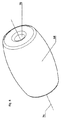
図1に示す本発明によるベース10は、立てられるべき物体250(図20を参照)を受け入れるための保持装置12を含む。図1に示す平面図では、主として上部要素14が可視である。底部要素16は保持装置12の領域内でのみ可視である。
The base 10 according to the invention shown in FIG. 1 comprises a holding
線II−IIに沿ったベース10の断面図が図2に示されている。受け入れ領域20内には、バラストウェイト60(図示せず)(例えば図5を参照)の受け入れ位置24が破線によって概略的に描かれている。バラストウェイト60が受け入れ領域20内に受け入れられた場合、これは受け入れ位置24内にある。受け入れ位置24から見た場合に半径方向内側を指す方向は、矢印26によって示されている。隆起領域28は受け入れ位置24の半径方向内側に配置されている。
A cross-sectional view of the
従って図2は、除去可能なバラストウェイト60を受け入れ位置24内に受け入れるための受け入れ領域20を有するベース10を示し、ここで、受け入れ位置24は半径方向外側に配置され、隆起領域28は、受け入れ位置24から進んで半径方向内側の周方向において少なくとも部分的に配置される。
FIG. 2 thus shows the base 10 with a receiving
隆起領域28は、受け入れ領域20に隣接する移送面32を含む。移送面32は、円錐台の外側面の形状を基本的に有する。移送面32は、ベース10のベース側40に対して約17°の角度36で傾斜されている。
The raised
ベース10の各設計に応じて、移送面32はベース側40に対して5°と30°との間の、好ましくは10°と22°との間の、特に12°と18°との間の全体的な角度36で傾斜されてもよい。
Depending on the design of the
上部要素14と底部要素16とは取り外し可能に又は取り外し不可能に互いに接続され、上部要素14は上部側84の方向において受け入れ領域20に隣接し、底部要素16はベース側40の方向において受け入れ領域20に隣接する。
The
ベース10のベース側40上にはノブ42が配置され、ノブ42はそれぞれが、図2には示されていない水平化要素136を受け入れるための円筒状の凹部43を有する。前記水平化要素136については図11に関連して以下で更に取り上げる。ベース10は、隆起領域28又は移送面32から見て半径方向内側に位置する送り込み領域44を含む。
On the
ベース10はそのベース側40上に摺動要素又は支持要素110を有する。個々の支持要素110はそれぞれがソケット112内に受け入れられ、それによりベース10内に固定される。支持要素110はポリマー材料から製造される。ポリマー材料は、バラストウェイト60がベース10内に受け入れられていない場合に個々の支持要素110が拡張状態にあるように選択される。この拡張状態は図2に示されている。拡張状態において、支持要素110はベース10の外部輪郭を超えて延在する。言い換えると、ベース10は、バラストウェイト60がベース内に受け入れられていない場合、支持要素110の上に立つ。
The
支持要素110の実施形態について以下で更に説明し、そこでは支持要素110は特に高度な様態で設計され、プライマリ支持要素252として示される。図20及び図21も参照されたい。
Embodiments of the
対照的に、バラストウェイト60がベース10内に受け入れられている場合、支持要素110はバラストウェイト60の重量によって圧縮される。この圧縮状態において、支持要素110はベース10の外部輪郭と同一平面上にある。言い換えると、支持要素110は、ベース10の外部輪郭を超えて延在しない。従ってベース10は、ノブ42の上に立つか、又は水平化要素136がノブ42の円筒状の凹部43内に配置されている場合は水平化要素136の上に立つ。
In contrast, when the
支持要素110のベース側の面114は、摺動を促進する被覆を備える。この被覆は気相蒸着セラミック層を含む。この被覆層は、材料の摩耗による疲労に対して耐性があり、同時に、滑りやすい、すなわち低い静止摩擦係数と滑り摩擦係数とを有する。
The base-
ベース10は図4において、分解された状態の斜視図で示されており、すなわち、上部要素14と底部要素16とが互いに分離している。先行する図1〜図3では、上部要素14と底部要素16とは互いに接続された状態で示されている。
The
本例において、上部要素14と底部要素16とは、底部要素16内に配置された周縁溝48と、図4において破線によって概略的にのみ示されている上部要素14の内側上に配置された周縁突出52とを介して互いに接続可能である。接続状態において、周縁突出52は周縁溝48内に係合し、それにより上部要素14と底部要素16とは圧力嵌め及び形状嵌めで互いに接続される。
In this example, the
図5は、前記の図で示したベース10に重みをかけるためのバラストウェイト60を示す。バラストウェイト60はいくつかの個別のウェイトすなわちバラスト要素64を含み、それらのうちの1つのみが図5において参照符号を有している。バラスト要素64は、現在の場合、コード様に設計された細長い接続手段68によって互いに接続される。この場合、コード様(code−like)とは、参照符号72を有する矢印によって示される縦方向における伸張に直交する接続手段68の可撓性又は変形性を許可する接続手段68の構造を意味する。その上、接続手段68は縦方向においても変形可能であってもよい。しかしこれは、用語「コード様」の意味の範囲内で本質的ではない。従って、縦方向においては剛性であるが、縦方向に直交して可撓性である接続手段68は、やはり用語「コード様」に該当する。
FIG. 5 shows a
好ましくは、バラストウェイト60は、互いに可撓式に接続されたか又は接続可能な様々なバラスト要素64、好ましくは互いに可撓式に接続された様々な実質的に球状の、円筒状の、又は樽形状のバラスト要素64を含む。あるいは、バラスト要素64のための任意のその他の転動可能な実施形態が使用されてもよい。バラストウェイト60のバラスト要素64は、図6において拡大斜視図で示されている。現在の場合、バラスト要素64は樽形状であるように設計される。
Preferably, the
バラストウェイト60は、その想像上の縦軸74に沿って貫通穴76を有する。貫通穴76は接続手段68を収容する働きをし、それによりいくつかのバラスト要素64が接続手段68上で言わば糸を通されて、バラストウェイト60を形成することが可能である。好ましくは接続手段68は、バラスト要素64を互いに間隔をおいて配置する局所的周拡張部(local peripheral expansions)を有する。
The
図5におけるバラストウェイト60のバラスト要素64は、及び従って図6におけるバラスト要素64も同様に、金属材料からなる。バラストウェイト60が金属材料を含む場合、好ましくは、バラストウェイト60が互いに可撓式に接続された様々なバラスト要素64を含み、少なくとも1つのバラスト要素64、好ましくは全てのバラスト要素64が金属材料を含む場合も、本発明の範囲内にある。
The
図7は、図1〜図4からのベース10、及びベース10に接続された同一のベース10bを示す。ベース10の要素に対応するベース10bの要素は、対応する参照番号をインデックスbで有する。
FIG. 7 shows the base 10 from FIGS. 1-4 and the
ベース10と、同一に設計されたベース10bとの間の接続は、ベース側40b上に形成された突出領域80bと、ベース側40の反対側の上部側84上に形成された凹部領域88とによって実現される。凹部領域88、88bは突出領域80、80bと相補的であるように設計される。この場合、相補的とは、一方のベース10又は10bの突出領域80、80bが、他方のベース10b又は10の凹部領域88、88b内に、好ましくは形状嵌め及び/又は圧力嵌めで挿入可能であることを意味する。
The connection between the base 10 and the identically designed
図8は、バラストウェイト60を有するベース10を示し、ここで、バラストウェイト60は受け入れ領域20内の受け入れ位置24内に受け入れられている。バラストウェイト60は、隆起領域28によって受け入れ領域24内に保持される。
FIG. 8 shows the base 10 having a
バラストウェイト60は、挿入装置90を用いて送り込み領域44内に導入されてもよい。挿入装置90は、バラストウェイト60がその上に配置されてもよい挿入面94を有する。挿入面94上に配置された後、バラストウェイト60は、重力下で移送面32を横断し、それにより受け入れ位置24内に移動する。重力下でバラストウェイト60は、その樽形状のバラスト要素64を用いて挿入面94及び移送面32上を言わば転動して、受け入れ位置24内に入る。
The
好ましくは、挿入面は円錐台の外側面の形状を実質的に有し、ベース側40に対して7°と35°との間の、好ましくは12°と25°との間の、特に15°と20°との間の角度で全体として傾斜される。
Preferably, the insertion surface has substantially the shape of the outer surface of the truncated cone, and is between 7 ° and 35 ° relative to the
図9は、図1に対応するベース10の描写を示す。図9には、保持装置12の幾何学的中心点100も示されている。外円102は、ベース側40を見た場合にベース10を完全に囲む可能な最小の円である。ベース10の回転対称の設計により、外円102は本例ではベース10の外部輪郭と一致する。しかし、本発明によるベース10の他の異なる形状の実施形態では、必ずしもそうとは限らない。
FIG. 9 shows a depiction of the base 10 corresponding to FIG. FIG. 9 also shows the
第1の内円104は、外円の直径の50%に一致する直径を有する。第2の内円106は、外円102の直径の60%に一致する直径を有し、第3の内円108は、外円102の直径の65%に一致する直径を有する。バラストウェイト60の受け入れ位置24は、バラストウェイト60の全部が、及び従って本例示的実施形態においてはその質量の100%が、3つの内円104、106、及び108の外側にあるように位置する。内円104、106、及び108の中心点は、保持装置12の中心点100に一致する。
The first
ベース10の回転対称の設計により、外円102の中心点も、保持装置12の中心点100に一致する。本発明によるベース10の異なる形状の実施形態では、保持装置12の中心点100は外円102の中心点と必ずしも一致しない。
Due to the rotationally symmetric design of the
好ましくは、ベース側40を見たときにバラストウェイト60の質量の少なくとも80%、好ましくは90%、特に100%が内円104、106、108の外側にあるように、バラストウェイト60は受け入れ位置24内に配置され、内円104、106、108の円中心点は保持装置12の幾何学的中心点100であり、内円104、106、108の直径は外円102の直径の少なくとも50%、好ましくは60%、特に65%であり、外円は、ベース側40を見たときにベース10を完全に囲む可能な最小の円102である。
Preferably, the
図10は、ベース10、及びベース10に接続された同一のベース10bを示す。保持インサート118、118bが、ベース10、10bの各保持装置12、12b内に受け入れられている。図10では、保持インサート118、118bは中空円筒状のアダプタ要素120、120bとして設計されている。立てられるべき物体250が、内部キャビティ124、124b内に挿入されるか又は押し込まれてもよい。この挿入は好ましくは圧力嵌めである。立てられるべき物体250はこれにより、本発明によるベース10内に有利に固定されることが可能である。保持インサート118、118bはそれぞれが接触面128、128bを有する。図10に示す構成では、接触面128は第2の実質的に同一のベース10bの突出領域80bと接触している。接触面128は、実質的に同一の第2のベース10bの重量による力を、ベース10のベース側40にそらすように設計される。この力は次に、ベース10が置かれている地面に作用する。
FIG. 10 shows the
アダプタ要素120、120bとしての保持インサート118、118bの設計は、例としてのみ理解されるべきである。ベース10又は10bの上部側において開いた本質的に円筒状の着座空間を有する、スリーブの形態における代替の実施形態が考えられ、ここでスリーブは、着座空間内にネジ込まれることが可能な少なくとも1つのネジ山付きボルトを有する。それにより、例えば立てられるべきクリスマスツリーが、ネジ山付きボルトをスリーブ内にネジ込むことによって固定され、従ってベース10内に立てられ得る。
The design of the retaining inserts 118, 118b as
図11は、傾斜面134上に設置されたベース10を示す。面134の角度を補償するために、ノブ42内の円筒状の凹部43内に水平化要素136が配置される。ノブ42の位置に応じて、水平化要素136は、異なる程度までノブ42から突出する。これにより面134の角度が補償され得る。
FIG. 11 shows the base 10 installed on the
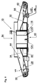
図12は、立てられるべき少なくとも1つの物体250(現在の場合、テーブルトップ200、及びパラソル250のための保持管213)を保持するためのベース10を示し、ここで、ベース10は、支承面212上に配置するために備えられるベース面214と、ベース面214の実質的に反対側の受け入れ面216とを有し、少なくとも1つの溝218を有する受け入れ機器220が、中空円筒222を受け入れるために受け入れ面216の領域内に配置される。図面はベース10を部分断面図で示す。
FIG. 12 shows a
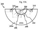
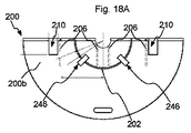
現在の場合、図12の底部領域においてベース10は、支承面212上に位置するテーブル足(参照番号なし)を含み、中空円筒222に関連して曲げられたプレート300(図14を参照)を図12の中間領域において含み、テーブルトップ200を図12の上部領域において含む。テーブルトップ200は、図12では暗に示されているのみである。テーブルトップ200は、図17A〜図19Cにおいてより詳細に示されている。
In the present case, in the bottom region of FIG. 12, the
他の実施形態では、ベース10は、支承面212上に位置するテーブル足を含むのみであってもよく、又はテーブル足を中空円筒222と一緒に含むのみであってもよい。
In other embodiments, the
現在の場合、ベース10は、(保持管213と同心状に伸びる)縦軸224に対して実質的に回転対称であるように設計される。ベース10の他の実施形態では、テーブル足、及び/又は中空円筒222、及び/又はテーブルトップ200は楕円形、長方形、又は正方形であるように設計される。
In the present case, the
現在の場合、テーブル足内にベース10は、ベース10の半径方向外側の周縁受け入れ位置24内に受け入れられた2つのバラストウェイト60を含む。バラストウェイト60はそれぞれが、接続手段68(図面では不可視)を用いて互いに接続された、おおよそ樽の形状に設計された複数のバラスト要素64を含む。接続手段68は、例えば、コード、ストリング、又はチェーンである。バラストウェイト60は、円錐台として設計されたベース10の移送面32によって受け入れ位置24内に保持される。
In the present case, the base 10 in the table foot includes two
バラストウェイト60は、(実質的に回転対称であるように設計された)挿入装置90を用いて送り込み領域44内に導入されてもよい。これは、中空円筒222が溝218内に取り付けられる前に行われる。挿入装置90は、バラストウェイト60がその上に配置されてもよい挿入面94を有する。挿入面94上に配置された後、バラストウェイト60は、重力下で移送面32を横断し、それにより受け入れ位置24内に移動する。重力下でバラストウェイト60は、その樽形状のバラスト要素64を用いて挿入面94及び移送面32上を言わば転動して、受け入れ位置24内に入る。
The
更にベース10は、中央に配置されたフォールディング装置238を含み、その中には現在の場合、パラソル250(図示せず)のための保持管213が蝶ネジ(参照番号なし)を用いて配置される。一方で保持装置238は、ベース10内の縦軸224に関して中央に配置されたアダプタ機器400内に保持される。以下の図22A〜図22Dも参照されたい。
Furthermore, the
図12の底部ハウジングセクション242において、ベース10は複数の支承要素110(「ノブ」)を有し、これを用いてベース10は支持面212上に位置する。支承要素110の底面は一緒に、ベース10のベース面214を特徴付ける。
In the
一実施形態では、溝218は、特に、ベース面214に平行な平面内で少なくとも部分的に楕円形であるように設計される。図12では、溝218は、ベース面214に平行な平面内で少なくとも部分的に円形であるように設計されている。従って現在の場合、中空円筒222は円形円筒である。
In one embodiment,
図示されていない一実施形態では、溝218は、特に、ベース面214に平行な平面内で少なくとも部分的に多角形であるように設計される。
In one embodiment, not shown, the
図示されていない別の実施形態では、溝218は、特に、ベース面214に平行な平面内で少なくとも部分的に曲線、例えば一般的な曲線として設計され、従ってまた、特に、楕円形又は多角形の溝よりもはるかに複雑な形状を有してもよい。例えば溝は、少なくとも部分的に、放物線形状又は双曲線形状などを有してもよい。
In another embodiment, not shown, the
図12において、溝218は、特に、ベース面214に平行な平面内で閉じた経路を有する。これに対応して、溝218は、ベース10の縦軸224の半径方向周囲を通るように設計される。
In FIG. 12, the
一般に、そのような半径方向周縁溝218はまた、受け入れ機器220によって形成される円筒の内側であると理解されてもよく、極端な場合、溝218の半径方向内側の「範囲を定める壁」は無視できるほど小さい半径を呈する。このケースは、例えば図12において挿入装置90が除去された場合に得られる。特に中空円筒222が比較的厚い材料を有する場合、中空円筒222は依然として好適な安定性を有して受け入れ機器220内に配置され得る。
In general, such a radial
図示されていない一実施形態では、溝218は、特に、ベース面214に平行な平面内で開いた経路を有する。例えば図12において、溝218はベース10の縦軸224の半径方向周囲を通るように設計され、しかし溝218は、例えば材料を節約するために1回又は複数回中断される。例えば溝はまた、「C」形状を有してもよい。
In one embodiment, not shown, the
もちろん溝218は、中空円筒222を収容できるように、(図12におけるように)半径方向断面平面内の上部において「開いて」いるように常に設計される。
Of course, the
ベース10の図示されていない一実施形態では、受け入れ面216は少なくとも部分的に、実質的に平坦、特に、ベース面214に実質的に平行であるように設計される。
In one non-illustrated embodiment of the
別の実施形態では、受け入れ面216は少なくとも部分的に、特にベース10の縦軸224に関する半径方向において傾斜されるように設計される。
In another embodiment, the receiving
図12の実施形態において、受け入れ面216は円錐台の外側面の形状を有する。ベース面214に対する円錐台の角度は、10°〜80°の範囲内の、好ましくは10°〜50°の範囲内の、更により好ましくは12°〜20°の範囲内の値を有する。図12では、角度は約16°である。
In the embodiment of FIG. 12, the receiving
すでに説明したように、中空円筒222は受け入れ機器220内に受け入れられる。特に、中空円筒222は、受け入れ機器220の溝218内に取り外し可能に受け入れられる。これに対応して中空円筒222は、ベース面214に平行な平面内で円形断面を有する。
As previously described,
ベース10の他の実施形態では、中空円筒222は、ベース面214に平行な平面内で少なくとも部分的に楕円形、又は円形、又は多角形であるように、あるいは湾曲しているように設計された断面を有する。
In other embodiments of the
別の実施形態では、中空円筒222は実質的に単一片として設計される。現在の場合、中空円筒222は可撓性の及び/又は捩り可能なプレート300(図14を参照)を含み、プレート300は、中空円筒222の形状に曲げられる及び/又は捩られるように設計される。可撓性の及び/又は捩り可能なプレート300が容易に移送可能であることは特に有利である。例えば移送する場合、複数のプレート300が互いの上に平坦に配置されて最小の体積がもたらされ得る。
In another embodiment,
一実施形態では、中空円筒222は、ベース面214に平行な平面内で、周囲の周りで一体的に接合されるように設計される。例えば、プレート300の対向するエッジセクションが溶接又は接着を用いて閉じた形状に接合される。
In one embodiment,
代替の実施形態では、中空円筒222は、ベース面214に平行な平面内で、それ自体とのオーバラップ又は突き合わせ継手を有する。好ましくは、中空円筒222の2つのエッジセクションを互いに接続してオーバラップ又は突き合わせ継手とするための手段が利用可能である。
In an alternative embodiment,
図12から更にわかるように、ベース10は、受け入れ機器220内に、特に、受け入れ機器220の溝218内に受け入れられた中空円筒222を含む。現在の場合、ベース10は、ベース10から離れる方を向いた中空円筒222の端セクション上に配置されたテーブルトップ200を含んでもよい。中空円筒222は、ベース10の(図12の底部における)テーブル足内に中空円筒222が受け入れられる方法に類似した(しかし必ずしも同等ではない)様式で、テーブルトップ200に接続されてもよい。
As can be further seen from FIG. 12, the
以下で更にわかるように、テーブルトップ200は、現在の場合、中空円筒222の端セクションを収容するための半径方向周縁溝202を有する。更に、テーブルトップ200又はテーブルトップ200内の中央に配置された環状要素204は、保持管213、特に、パラソルスタンドのための保持管213の外側を囲むように及び/又は半径方向で保持するように設計された、実質的に中央の開口(参照番号なし)を含む。
As will be seen further below, the
更に、テーブルトップ200内の穴206が図12に示されており、穴206により、2つの少なくともおおよそ半分の部分的テーブルトップ200a及び200b(図17A〜図19Cを参照)を互いに接続することが可能になる。この目的のために、ロック手段210がテーブルトップ200上に加えて存在する。
In addition, a
図13は、図12からのベース10の第1のセクションを拡大図で示す。中空円筒222は、ベース10の方を向いた端セクションにおいて、中空円筒222をスタンド10に接続するように設計されたバヨネットロック244の少なくとも1つの部分を有する。前記端セクションは、溝218によって実質的に囲まれる。
FIG. 13 shows the first section of the base 10 from FIG. 12 in an enlarged view. The
その第1のバージョンでは、バヨネットロック244の少なくとも1つの部分は、中空円筒222内の少なくとも1つのカットアウト304によって形成される(図14を参照)。第2のバージョンでは、バヨネットロック244の少なくとも1つの部分は、中空円筒222内の少なくとも1つのピン様の刻印によって形成される。この場合、受け入れ機器220は、バヨネットロック244の対応する相補的部分を含む。
In its first version, at least one portion of
同様の様態で、テーブルトップ200と中空円筒222も、少なくとも1つのバヨネットロック208を用いて互いに接続されてもよい(図12)。この目的のために、中空円筒222の端セクションは少なくとも1つのカットアウト308(好ましくは複数のカットアウト308)を、バヨネットロック208の第1の部分のために有し、テーブルトップ200は少なくとも1つのボルト240を、バヨネットロック208の第2の部分のために有する。以下、特に、図14、図19B、及び図19Cを参照されたい。
In a similar manner, the
図15及び図16と一緒に図14は、可撓性の及び/又は捩り可能な、かつ実質的に多角形、好ましくは長方形の形状に設計されたプレート300を示す。図からわかるように、プレート300は現在の場合、(図14の底部における)第1の側302において、第1の側302に対して開いた6つのカットアウト304を有し、カットアウト304は、第1の側302のエッジ302aから進んで、エッジ302aに対して少なくともおおよそ直角に延在する第1のセクション304aを含み、カットアウト304は、第1のセクション304aから進んで、次に、エッジ302aに少なくともおおよそ平行に延在する第2のセクション304bを含む。図15を参照されたい。
FIG. 14 together with FIGS. 15 and 16 show a
例えば第1のセクション304aは、エッジ302aに対して約70°〜110°の、好ましくは約80°〜約100°の角度を有する。現在の場合、この角度はほぼ90°である。例えば第2のセクション304bは、エッジ302aに対して約+10°〜約−10°の、好ましくは約+4°〜約−4°の角度を有する。現在の場合、この角度はほぼ0°である。この場合、第1のセクション304a及び第2のセクション304bはそれぞれが、少なくともおおよそ一定の幅(参照番号なし)を有する。
For example, the
その上、カットアウト304は少なくともおおよそL形状を有することが図15からわかり、第1のセクション304a及び第2のセクション304bはそれぞれがL形状の脚に対応する。加えて、第2のセクション304bは幅の局所的狭化304cを有する。第2のセクション304bの幅の局所的狭化304cは、第1のセクション304aから進んで、第2のセクション304bの長さの約60%を超えて第1のセクション304aから隔たっている。カットアウト304はバヨネットロック244の一部として設計される。
Moreover, it can be seen from FIG. 15 that the
更に、プレート300は、少なくとも(図14の上部における)第2の側306において、第2の側306に向けて開いた少なくとも1つのカットアウト308を有することが図14からわかり、第2の側306は好ましくは第1の側302の反対側に位置する。現在の場合、第2の側306における4つのカットアウト308は、第1の側302の少なくとも1つのカットアウト304の形状と少なくともおおよそ同等の形状を有する。これに対応して、カットアウト308はそれぞれが第1のセクション308aと第2のセクション308bと局所的狭化308cとを有する(図16を参照)。図14から更にわかるように、第2のカットアウト308の第1の及び/又は第2のセクション308a及び308bの幅は、それぞれ、第1のカットアウト304の比較可能な幅より小さい。
In addition, it can be seen from FIG. 14 that the
好ましくは、第1の側302及び第2の側306のカットアウト304及び308のそれぞれの脚であって、それぞれの脚302a及び306aから離れる方を向くように配置されたそれぞれの脚は、互いに反対方向に延在する。利点は、ベース10の第1のセクション上に中空円筒222を取り付けた後に、中空円筒222上にテーブルトップ200も取り付け可能であり、各バヨネットロック244及び208を係合させる場合に、同じ方向における回転方向が特に実現可能である、ということである。
Preferably, the respective legs of the
好ましくは、プレート300の第1の側302及び第2の側306内に2つ以上のカットアウト304及び308が配置され、エッジ302a及び306aに沿って、1つの側302上にそれぞれがある2つのカットアウト304の間の少なくとも1つの距離は、他方の側306上にそれぞれがある2つの比較可能なカットアウト308の間の距離とは異なる。利点は、ベース10の第1のセクション上に又はテーブルトップ200上に中空円筒222を取り付ける際に側302と306とが間違って入れ換わった場合、特に現在の場合はより小さいカットアウト308が損傷され得ない、ということである。
Preferably, two or
好ましくは、プレート300の厚さは10mm以下、好ましくは5mm以下、更により好ましくは2mm以下である。例えばプレート300は、金属及び/又はプラスチック材料、及び/又は厚紙材料を含む。一実施形態では、中空円筒222の外側面は、刻印、印刷、糊付け、及び/又は塗装された文字及び/又は図形情報310を有する。これは例えば、大きな文字「P」によって示されている。
Preferably, the thickness of the
プレート300の一実施形態では、第1の側302又は第2の側306のエッジ302a又は306aの長さは、約30cmと約320cmとの間、好ましくは約60cmと約160cmとの間である。好ましくは、中空円筒222の直径又はそれに相当する寸法は、ベース10(又は前記テーブル足)の直径又はそれに相当する寸法の少なくとも20%、好ましくは少なくとも40%である。
In one embodiment of the
別の実施形態(図示せず)において、プレート300は、連続する一連の複数の要素であってプレート300の平面内で互いに接続された複数の要素を有する。例えば要素は、ブラインドの場合と同様の薄板として設計される。好ましくは要素の接続は、可撓性、回転可能、及び/又は関節式であるように設計される。第1のバージョンでは、要素は、例えばプレート300の厚さの局所的減少による、特定の屈曲(「可撓性」)ポイントを有する。これはいわゆる「フィルムヒンジ」としても知られている。第2のバージョンでは、要素は、第1の縦側上に棒形状の「シャフト」を有し、これに対応して、第2の縦側上に環状の(「回転可能な」)「ブッシング」を有する。第3のバージョンでは、ブラインドによって知られているように、2つの要素が各場合において互いにフック様に(「関節式に」)把持する。このようにしてプレート300は、要素自体が剛性であるように設計されている場合でも「可撓性の」及び/又は「捩り可能な」特性を備え、中空円筒222に対応して成形可能である。
In another embodiment (not shown),
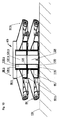
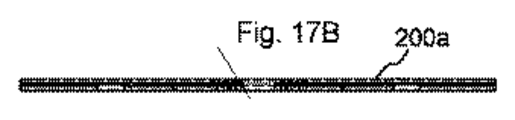
図17A〜図17C、図18A〜図18C、及び図19A〜図19Cはテーブルトップ200の実施形態を示し、テーブルトップ200は、実質的に半円形であるように設計された2つの部分的テーブルトップ200a及び200bを含む。2つの部分的テーブルトップ200a及び200bの1つの接続セクション(参照番号なし)において、一方の部分的テーブルトップ200aは溝を有し(図17A〜図17C)、他方の部分的テーブルトップ200bはバネを有する(図18A〜図18C)。
17A-17C, 18A-18C, and 19A-19C illustrate an embodiment of a
図17A及び図18Aはそれぞれ、部分的テーブルトップ200a及び200bの、下からのすなわち支承面212から見た図を示す。図17B及び図18Bはそれぞれ、90°回転された図17A又は各図18Aの図を示す。図17C及び図18Cはそれぞれ、90°回転された図17B又は各図18Bの図を、従って部分的テーブルトップ200a及び200bの平面図を示す。図17C及び図18Cにおいて破線を用いて示されている要素は、図17A及び図18Aからの参照番号を使用して識別可能である。更に、図17A及び図18Cにおける部分的テーブルトップ200a及び200b内にカットアウト領域が存在し、その中にボルト保持装置246が(それぞれ中空円筒222上に配置するためのバヨネットロック208の一部として)配置されてもよい。
17A and 18A show views of the partial table tops 200a and 200b from below, respectively, as viewed from the bearing
好ましくは、2つの部分的テーブルトップ200a及び200bを互いに接続するための手段が利用可能である。この手段は現在の場合、テーブルトップ200の平面内に延在する部分的テーブルトップ200a及び200b内の穴206の中に配置されてもよい、棒形状の要素を含む。これにより十分な機械的安定性を有するテーブルトップ200が提供される。加えて、ラッチング手段210(又はスナップコネクタ)が、部分的テーブルトップ200a及び200bを特に接続するために利用可能である(図12を参照)。
Preferably, means for connecting the two partial table tops 200a and 200b to each other are available. This means comprises, at present, a bar-shaped element which may be arranged in a
もちろん、テーブルトップ200又は2つの部分的テーブルトップ200a及び200bの組み合わせは、任意の所望の形状を有してもよい。例えばこの形状は、長方形、円形、楕円形、又は長円形であってもよい。
Of course, the
図19A〜図19Cはそれぞれ、90°回転されたボルト保持装置246の図を示す。
19A to 19C each show a view of the
図20は、立てられるべき少なくとも1つの物体250を保持するためのベース10の単純化された部分断面図を示し、ベース10は少なくとも1つのプライマリ摺動要素又は支持要素252を含み、これは弾性変形可能な第1の部分体252aと、第1の部分体252a内に配置された、セラミック材料を含む少なくとも1つの第2の部分体252bとを有する。図20では4つのプライマリ支持要素252が可視である。
FIG. 20 shows a simplified partial cross-sectional view of the
以下では、立てられるべき物体250は、例えばパラソル250によって特徴付けられ、そのためパラソル250も参照番号250を用いて識別される。従って図20はまた、パラソルスタンドを示す。
In the following, the
ベース10は、概略的にのみ示された支承面212上に位置する。支承面212は例えば、床、敷き詰め絨毯、タイル又は岩又はアスファルト舗装で覆われた表面、あるいは地面である。この場合、第2の部分体252bは地面212上に位置する。第1の部分体252aの体積の少なくとも一部はベース10内にあり、従って図面において第2の部分体252bの上に配置されている。
The
現在の場合、パラソル250は、保持装置238(図20では不可視)(図12及び図13を参照)を用いてベース10内に保持される保持管213を含む。例えば、保持管213はパラソル250を有するモジュラユニットとして設計される。図示されていない他の実施形態では、立てられるべき物体250は、クリスマスツリー、テーブル、又は事務用椅子などの椅子である。
In the present case, the
ベース10の別の実施形態では、第2の部分体252bは、金属、プラスチック、木、硬質ゴム、セメント、又はガラスを含む。前述の材料により、摩擦特性、弾性、及び/又は疲労強度に関する、対応する差がケースバイケースでもたらされ得る。
In another embodiment of the
ベース10の一実施形態では、第2の部分体252bは第1の部分体252aに、形状嵌め、及び/又は圧力嵌め、及び/又は一体接合によって接続される。例えば、第2の部分体252bは第1の部分体252aに、接着によって接続される。
In one embodiment of the
ベース10の一実施形態では、第2の部分体252bは第1の部分体252a上の気相蒸着、特に、セラミック材料の気相蒸着によって製造される。
In one embodiment of the
一実施形態では、第1の部分体252aは、圧力に応答することが可能なゴム、及び/又は発泡体、及び/又はプラスチック、及び/又はバネを含む。
In one embodiment, the
例えば第1の部分体252aは、10kN/mm2未満の、好ましくは5kN/mm2未満の、より好ましくは1kN/mm2未満の弾性係数を有する。同様に、第1の部分体252aのショアA硬度は、50未満、好ましくは20未満、より好ましくは10未満であってもよい。
For example, the
図20からわかるように、第1の部分体252aの、図面における垂直寸法、従って体積は、第2の部分体252bの対応する寸法及び体積より大きい。ベース10の各実施形態に応じて、第1の部分体252aの体積の、第2の部分体252bの体積に対する比率は好ましくは、1以上の値を、好ましくは20以上の値を、より好ましくは500以上の値を有する。従って第2の部分体252bは比較的薄いように設計されてもよいが、但しそれが絶対に必要とは限らない。
As can be seen from FIG. 20, the vertical dimension, and thus the volume, of the first sub-body 252a in the drawing is greater than the corresponding dimensions and volume of the second sub-body 252b. Depending on each embodiment of the
一実施形態では、第2の部分体252bは、0.3kN/mm2より大きな、好ましくは10kN/mm2より大きな、より好ましくは25kN/mm2より大きな弾性係数を有する。例えば特定の「セラミック」は、タイプに応じて約0.3kN/mm2〜約30kN/mm2の弾性係数を有し得る。同様に、第2の部分体252bのショアD硬度は、80より大きくてもよく、好ましくは100より大きくてもよく、より好ましくは150より大きくてもよい。
In one embodiment, the
図示されていない一実施形態では、プライマリ支持要素252はネジを用いて、特にプライマリ支持要素252をベース10内にネジ込むことによってベース10内に保持される。例えばそのプライマリ支持要素252はネジ山付きセクション(図示せず)を含む。あるいは、プライマリ支持要素252はスナップ留めによってベース10内に保持されてもよい。
In one embodiment, not shown, the
更に、ベース10はセカンダリ摺動要素又は支持要素254を含み、特に無負荷状態においてプライマリ支持要素252は、ベース10のベース平面から、セカンダリ支持要素254が延在するよりも遠くまで延在する。これは次の図21において示されている。図20の実施形態において、セカンダリ支持要素254はベース10の底部ハウジングセクション又は底であり、ベース10は、支承面212の方を向いた底部側上で実質的に平坦であるように設計される。
Further, the
実施形態に応じて、セカンダリ支持要素254は、0.1kN/mm2以上の、好ましくは5kN/mm2以上の弾性係数を有する。
Depending on the embodiment, the
好ましくはベース10は、プライマリ支持要素252の第2の部分体252bの(支承面212の方を向いた)面が、基準面(これは例えば支承面212に対応する)に対する第1の摩擦係数を有し、セカンダリ支持要素254の面が、同じ基準面に対する、第1の摩擦係数より大きな第2の摩擦係数を有するように設計される。
Preferably, the
一実施形態では、プライマリ支持要素252は複合材料を含み、複合材料の少なくとも1つの第1の構成材料はゴム弾性材料を含む。特に、ゴムの弾性特性が利用される。
In one embodiment,
ベース10の図示されていない一実施形態では、少なくとも1つのローラ、シリンダ、又は転動可能な球を含む少なくとも1つの追加の支持要素が備えられる。好ましくはプライマリ支持要素252は、圧力に応答するバネ、好ましくはコイルバネ又は板バネを用いてベース10の本体上に配置される。
In one non-illustrated embodiment of the
例えば前記追加の支持要素は、プライマリ及びセカンダリ支持要素254及び254に加えて備えられてもよく、又はプライマリ支持要素252は他の支持要素によって置き換えられてもよい。後者の場合、ベース10は例えば、(弾性材料を有する第1の部分体252aなしに)バネを用いて支承面212に押し付けられるローラを有してもよく、それにより図20の実施形態と同様の機能がもたらされる。
For example, the additional support elements may be provided in addition to primary and
好ましくは、プライマリ支持要素252の(又は第1の支持体252aの)弾性定数又はバネ定数は、ベース10が初期重量を受ける場合に、少なくとも1つのセカンダリ支持要素254に加えて少なくとも1つのプライマリ支持要素252が支承面212に押し付けられることが可能であるように(図20)、及び、ベース10が第1の重量より小さい第2の重量を受ける場合に、少なくとも1つのセカンダリ支持要素254が支承面212から持ち上がることが可能であるように(図21)存在する。
Preferably, the elastic or spring constant of the primary support element 252 (or of the
例えば図20による第1の重量は、ベース10の固有重量と、ベース10内に必要に応じて配置可能な1つ以上のバラストウェイト60(例えば図8、図12、又は図13を参照)と、パラソル250の重量とによってもたらされる。
For example, the first weight according to FIG. 20 includes the specific weight of the
第2の重量は、例えば、ベース10から部分的に除去されたパラソル250、及び/又はベース10から少なくとも部分的に除去されたバラストウェイト60に対応する。これは図21に示されている。保持管213がパラソル250を有するモジュラユニットとして設計される限りにおいて、両方の要素250と213とが一緒に除去される。
The second weight may correspond to, for example,
このようにして減少された重量に対応して、セカンダリ支持要素254は従って支承面212から持ち上がってもよい。それによりベース10は、プライマリ支持要素252のみを用いて支承面212上に載る。上述のように第2の部分体252bは支承面212に対して比較的低い摩擦を有するため、図21の状態においてベース10は、比較的小さな力を用いて支承面212上を移動可能であり、従ってベース10を更に持ち上げる必要なしに移送可能である。
Corresponding to the reduced weight in this way, the
図示されていない一実施形態では、立てられるべき物体250は事務用椅子などの椅子であり、従ってこれはベース10上に配置される。
In one embodiment, not shown, the
図示されていない別の実施形態では、立てられるべき物体250は単一脚のテーブルなどのテーブルであり、従ってこれはベース10上に配置される。
In another embodiment, not shown, the
理解のために、以下で説明する図のうちのいくつかにおいては寸法(ミリメートル単位)が示される。しかし全ての寸法は例にすぎないということを明示的に述べておく。本発明は、それらから大幅に逸脱する寸法を用いても、及び/又はそれらから大幅に逸脱する比率を用いても、及び/又はそれらから大幅に逸脱する詳細を用いても設計可能である。 For the sake of clarity, dimensions (in millimeters) are shown in some of the figures described below. However, it is explicitly stated that all dimensions are only examples. The present invention can be designed with dimensions that depart substantially therefrom and / or with ratios that depart substantially from them, and / or with details that depart substantially from them.
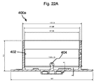
図22Aは、立てられるべき物体250を保持するための、実質的に回転対称であるように設計された、第1のアダプタ機器400の底部ネジ山付きスリーブ400aの、図22Cからの線A−Aに対応する断面図を示す。図12及び図13も参照されたい。底部ネジ山付きスリーブ400aは、内部ネジ山402とセンタリングピン404とを含む。
FIG. 22A shows a line A- from FIG. 22C of the bottom threaded
図22B及び図22Cは、底部ネジ山付きスリーブ400aの下からの及びそれぞれ上からの図を示す(図12、図13、及び図22Aを参照されたい)。図22Dは底部ネジ山付きスリーブ400aの「底部図」を示す。
FIGS. 22B and 22C show views from below and respectively from above of the bottom threaded
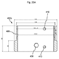
図23Aは、実質的に回転対称であるように設計された、第1のアダプタ機器400の上部ネジ山付きスリーブ400bの、図23Bからの線A−Aに対応する断面図を示す。上部ネジ山付きスリーブ400bは外部ネジ山406を有する。更に、六角形の開口408及び2つの円形ノブ410を図23Aで見ることができる。
FIG. 23A shows a cross-sectional view of the upper threaded
図23B及び図23Cは、上部ネジ山付きスリーブ400bの第1の半径方向図及び第2の半径方向図を示す。図23Dは、図23Bからの線B−Bに対応する上部ネジ山付きスリーブ400bの断面図を示す。図23Eは、上部ネジ山付きスリーブ400bの軸方向図を示す。
23B and 23C show a first radial view and a second radial view of the upper threaded
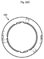
図24Aは、立てられるべき物体250を保持するための第2のアダプタ機器420の、図24Bからの線A−Aに対応する断面図を示す。現在の場合、2つの穴422が図24Aにおいて可視である。好ましくは、第2のアダプタ機器420の半径方向外部寸法は、第1のアダプタ機器400又は上部ネジ山付きスリーブ400bの半径方向内部寸法以下である。
FIG. 24A shows a cross-sectional view of the
図24Bは、第2のアダプタ機器420の第1の半径方向図を示す。図24Cは、第2のアダプタ機器420の第2の半径方向図を示す。図24Dは、第2のアダプタ機器420の別の図(「底部図」)を示す。
FIG. 24B shows a first radial view of the
ベース10の別の実施形態について、図25A〜図25Dは、実質的に中空円筒として設計され、ベース10の縦軸224と同心状にベース10内に配置される(又は配置可能な)支持管500を示し、支持管500は、立てられるべき物体250、特にテーブルトップ200を支承するように設計される。別の実施形態では、支持管500は、事務用椅子などの椅子の座部及び/又は背もたれを支承するように設計される。
For another embodiment of the
例えば支持管500は、50mm〜200mmの、好ましくは約80mm〜90mmの直径を有する。支持管500は、支持管500の半径方向平面内でそれぞれが延在する複数の開口502を有する。図25A及び図25Bからわかるように、開口502は部分的に中心指向であり、部分的に非中心指向である。複数の開口502は軸方向のグリッド内に配置される。
For example, the
開口502を用いてテーブルトップ200は、例えば、支持管500内に配置及び/又はロックされること、特に、高さ調節可能な様態で配置及び/又はロックされることが可能である。この目的のためにテーブルトップ200は中央開口を有する。例えば、テーブルトップ200の実施形態、及び図17A〜図18Cを参照されたい。
Using the
図25Aと同様に、図25Bは支持管500の軸方向図を示し、ここで、図25Bにおける図は半径方向に90°ずらしたものである。図25Cは、支持管500の半径方向「底面図」を示す。図25Dは、図25Aからの線A−Aに対応する断面図を示す。
Like FIG. 25A, FIG. 25B shows an axial view of the
好ましくは、支持管500の内径は、ベース10内に配置可能なパラソルスタンド(パラソル250)のための保持管213の外形より大きく、支持管500の直径は中空円筒222の直径より小さい。従って本発明によるベース10は、テーブル足、保持管213、支持管500、中空円筒222、及び/又はテーブルトップ200を含んでもよい。
Preferably, the inner diameter of the
ベース10の一実施形態では、支持管500は、少なくともおおよそ中空円筒として設計された少なくとも1つのアダプタ機器400又は420を用いて、ベース10内に保持されてもよい。これは図26に概略的に示されている。
In one embodiment of the
図26による実施形態は、上部ネジ山付きスリーブ400bが内部にネジ込まれることが可能な底部ネジ山付きスリーブ400aを示す。上部ネジ山付きスリーブ400bと一緒に、底部ネジ山付きスリーブ400aは第1のアダプタ機器400を形成する。第2のアダプタ機器420(図24A〜図24Dを参照)は、上部ネジ山付きスリーブ400bの半径方向内部セクション内に配置される。
The embodiment according to FIG. 26 shows a bottom threaded
支持管500は、第2のアダプタ機器420の半径方向内部セクション内に配置される。蝶ネジとして設計されたネジ接続412が、複数の可能な形状嵌め及び/又は圧力嵌め接続を表すために図26に概略的に示されている。六角形の開口408(図23A)も参照されたい。
The
図26はまた、支持管500がベース10内に形状嵌めで保持され、支持管500及び/又は少なくとも1つのアダプタ機器400及び420が少なくとも1つのネジ接続412を用いてベース10内に保持される、ベース10の実施形態を示す。現在の場合、図1において単に示唆された保持装置12は、図26に示す要素を含む。
FIG. 26 also shows that the
以下では、テーブルトップ200並びに部分的テーブルトップ200a及び200bの配置の追加の詳細について、図17A〜図19Cの説明に加えて説明する。要素の表示は上記で使用された表示とは部分的に異なる。しかし文脈により関連が確立される。
In the following, additional details of the arrangement of the
テーブルトップ200又は200a及び200bを支持管500内に固定するために、できるだけ容易に実行すること及び元に戻すことが可能な支持管500内への固定法が必要とされる。この問題を解決するためにロッキングピンが使用され、ロッキングピンは、対応する深さだけ部分的テーブルトップ200a及び200bの面内にあけられた穴に挿入される。支持管500の中央を通ってまっすぐに伸びる1本のロッキングピンのみが使用される場合、テーブル保持ピンが道を塞ぐため、パラソルポールは支持管500の中央に配置され得ない。しかし、2つの離心性のピン穴が使用される場合、支持管500の中央にパラソルポールを配置することが可能である。2つの支持ピンの間の間隙は正確に、2本の支持管ピンの間を全ての標準的なパラソルポール(15mm〜55mm)が通るのに十分なほど大きい間隔である。特に柔軟な様態でテーブルを使用できるように、支持管500内の穴はグリッド(50mm)内に導入される。これにより、テーブルトップ200又は200a及び200bの高さを個々に固定することが可能になる。
In order to secure the
延長支持管がベース支持管内に、スリーブプラグイン接続を介して導入されてもよい。テーブルトップ200又は200a及び200bがこの領域内に固定される場合にテーブル保持ピンが2本の結合されたパイプを通って伸び、それにより引張りに対抗して自動的にしっかりと固定するように、延長支持パイプ内の穴は精巧に配置される。
An extension support tube may be introduced into the base support tube via a sleeve plug-in connection. When the
ピンを用いたスリーブ挿入技術は特に有利であり、なぜならこれは例えばネジ式パイプよりはるかに速く取り付けられ得るからである。テーブルトップ200又は200a及び200bの底面側上では、テーブルトップ200又は200a及び200b内に深く引っ込んだトグル式ファスナ以外には他のいかなる接続手段も可視ではなく、それにより、テーブルトップが非常に高く搭載される必要がありテーブルトップの底部側が見える場合の、非常に優美な外観がテーブルトップに与えられる。加えて、移送中のテーブルトップ200又は200a及び200bの特に低い積み重ね高さがもたらされる。全ての接続要素がテーブルトップ200又は200a及び200b内に引っ込んでいるため、この高さはテーブルトップの厚さに正確に一致する。
The sleeve insertion technique with pins is particularly advantageous because it can be installed much faster than, for example, threaded pipes. On the bottom side of the
保持を向上するために、テーブルトップの片割れ200a及び200bはそれぞれが溝及びバネを備える。正方形又は長方形のテーブルトップ200又は200a及び200bが、それぞれ同じプラグイン接続を用いる1本の支持管500を有する少なくとも2つのベース10の間で固定される場合、テーブルはやはり立てられ得る。追加のコーナーピースが使用される場合、L形状、T形状、又はU形状のテーブル面200又は200a及び200bが立てられ得ると共に、パラソル250も次に支持管500内に挿入され得る。
To improve retention, the table
設置面が傾斜している場合、ベース10の底部側上の設置ノブ内に水平化要素136が挿入されているならば、テーブルはやはり立てられ得る。例えばダイニングテーブル又はハイテーブルトップなどのテーブルは、支持管500内のグリッド穴を使用して、最も好適な高さにおいて個々に立てられ得る。
If the mounting surface is inclined, the table can still be erected if the leveling
現在の場合、第2のアダプタ機器420の半径方向内部領域は、約85mmの直径を有する(図24Aを参照)。適合する直径を有するパラソルハンドル又は保持管213、あるいは支持管500が、その中に配置され得る。支持管500をベース10にしっかりと接続するために、固定ネジ(特に、1つ以上のネジ接続412)が、上部ネジ山付きスリーブ400bを通し、加えて第2のアダプタ機器420を通して、支持管500内にネジ込まれてもよい。これにより全ての構成要素の間の圧力嵌め及び形状嵌め接続が確立される。支持管500を有するベース10はこの場合、一体構造のユニットとして特徴付けられる。支持管500の大きな直径の利点は、より大きな内部レバーアームが力の伝達のために非常に有利であるということである。
In the present case, the radial inner area of the
互いに距離を隔てた2つのネジ山内にネジ込まれる場合にネジは問題を有する可能性があるため、好ましくは、このタイプの固定に伴って上部ネジ山付きスリーブ400b内にネジ山は存在しない。結果として、六角形の開口408と、上部ネジ山付きスリーブ400bから第2のアダプタ機器420への移行円錐部とが、上部ネジ山付きスリーブ400b内に見出される。支持管500がベース10にネジ留めされる場合、六角形の開口408は空きであり、蝶ネジのピンは第2のアダプタ機器420を直接通り抜ける。パラソル250又は保持管213、あるいはクリスマスツリーが立てられる場合、半径方向内側に配置された第2のアダプタ機器420は前もって除去され、フランジ付きM8ナットが六角形の開口408内に内側から挿入され、これを通してM8蝶ネジが案内される。スピードナットの傾斜フランジにより、第2のアダプタ機器420が支持パイプ500と共に再び使用される場合にナットを容易に除去することが可能になる。
Preferably, there are no threads in the upper threaded
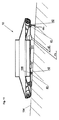
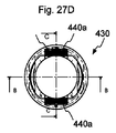
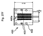
図27A〜図27Gは、ベース10の別の実施形態のための第3のアダプタ装置430のいくつかの図を示し、ここで、第3のアダプタ機器430は少なくとも1つの半径方向に作用するクランプ機器440を有し、クランプ機器440の半径方向の寸法は実質的に滑らかに適合可能である。
27A-G show several views of a
図27Aからわかるように、現在の場合、第3のアダプタ機器430の上部エッジの下の外径は79.1mmである。この直径は、図25A〜図25Dによる支持管500の上部内径に対応する。従って現在の場合、第3のアダプタ機器430は支持管500の半径方向内部に配置可能である。例えば第3のアダプタ機器430は、テーブル足から離れる方を向いた支持管500の端セクション内に配置されてもよい。
As can be seen from FIG. 27A, in the present case, the outer diameter below the upper edge of the
第3のアダプタ機器430が圧力嵌め及び/又は形状嵌めで支持管500内に上から完全に押し込まれた場合に、支持管500内の軸方向に配置された開口502と一致するように、第3のアダプタ機器430内の開口432が、軸方向の間隔をあけてアダプタ機器430内に適宜に配置される。従ってアダプタ機器430は、アダプタ機器400内に、及び支持管500内に挿入可能である。ネジ山付き接続412をアダプタ機器430のネジ込み凹部433(図27B、図27F、及び図27Gを参照)までネジ込むことによって、アダプタ機器430は上部ネジ山付きスリーブ400b内に固定される。
When the
現在の場合、クランプ機器440は、ベース10に、特に、強固に結合可能な少なくとも1つの第1のクランプ要素440aを含み、クランプ機器440は、第1のクランプ要素440aと立てられるべき物体250との間に半径方向に配置可能な少なくとも1つの第2のクランプ要素440b(図28A及び図28Bを参照)を含み、第1のクランプ要素440aは第1の接触面442aを有し、第2のクランプ要素440bは第2の接触面442bを有し、第1の接触面442a及び第2の接触面442bは少なくとも部分的に触接し、特に、触接面は少なくとも約20mm2の面積を含む。
In the present case, the
第1の及び/又は第2の接触面442a及び442bは、好ましくは、例えば波形、正弦形、半円形、鋸歯形、又は三角形であるように設計されたグリッド又はフルーティングなどを有する。比較的「滑らかな」接触面442a及び442bも可能であり、この場合は所与の摩擦が所望の効果を生成する。あるいは又は加えて、第1の及び/又は第2の接触面442a及び442bはまた、接触面442aと442bとの間の圧力嵌め及び/又は形状嵌めを可能にする、異なる、特に、不規則な及び/又は規則的な表面構造を少なくとも部分的に有してもよい。
The first and / or
図27A〜図27Gの実施形態において、第1の及び/又は第2の接触面442a及び442bは好ましくは、少なくとも部分的に、主として平坦であるように設計される。例えば、第1の及び/又は第2の接触面442a及び442bの全表面の90%よりも多くが平坦であるように設計される。
In the embodiment of FIGS. 27A-G, the first and / or
現在の場合、第1の及び/又は第2の接触面442a及び442bは実質的に長方形であるように設計されてもよく、ここで第1の又は第2の接触面442a及び442bの幅は第1の又は第2の接触面442a及び442bの長さより小さく、第1の又は第2の接触面442a及び442bの縦軸(参照番号なし)は好ましくは、ベース10の縦軸224と、約2°と約45°との間の、特に約5°と約30°との間の角度を形成する。
In the present case, the first and / or
好ましくは、第1のクランプ要素440a及び第2のクランプ要素440bは、少なくとも部分的に、いわゆる傾斜平面として設計され、それらの部分は互いに相補的であるように設計される。以下の図28Bを更に比較されたい。
Preferably, the
図27Aは、図27Dからの線B−Bに対応する第3のアダプタ機器430の断面図を示す。特に、第1の接触面442aを見ることができ、これは現在の場合、図面の垂直方向における個々の領域に分割されている。図27C、図27D、及び図27Fも比較されたい。図27Bは、図27Dからの線C−Cに対応する第3のアダプタ機器430の断面図を示す。
FIG. 27A shows a cross-sectional view of
図27C及び図27Dは、第3のアダプタ機器430の第1の半径方向図及び第2の半径方向図を示す。図27Eは、図27Cからの線D−Dに対応する断面図を示す。図27Fは「底部図」を示す。図27Gは補助図を示す。図27C〜図27Gにおける縮尺は、図27A及び図27Bに比較して小さい。
27C and 27D show a first radial view and a second radial view of the
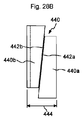
図28Aは、第2のクランプ要素440bの斜視図を示す。図28Bは、クランプ機器440の概略図を示し、半径方向寸法444はクランプ要素440a及び440bの相対位置に応じて変更可能である。
FIG. 28A shows a perspective view of the
図28Cは、2つの第2のクランプ要素440bがアダプタ機器430の半径方向内部領域内に配置された、第3のアダプタ機器430の斜視図を示す。図からわかるように、少なくとも1つのクランプ要素の少なくとも1つの表面、好ましくは第2のクランプ440bの表面、特に第1の又は第2の接触面442a及び442bの反対側の表面は少なくとも部分的にオイラーの螺旋の形状を有する。それにより保持管213は、保持管213の直径とほとんど無関係に、2つのクランプ要素440bの間にしっかりと保持され得る。
FIG. 28C shows a perspective view of the
Claims (17)
前記隆起領域(28)は、前記受け入れ領域(20)に隣接する移送面(32)を備え、
前記ベース(10、10b)は、前記バラストウェイト(60)が挿入され得る送り込み領域(44)を備え、前記送り込み領域(44)は、前記バラストウェイト(60)が挿入後に重力下で前記移送面(32)を横断して前記受け入れ位置(24)内に移動するように設計され、且つ
挿入面(94)を有する挿入装置(90)が前記保持装置(12)と前記送り込み領域(44)との間に配置され、前記挿入面(94)は円錐台の外側面の形態を有し、ベース側(40)に対して7°と35°との間で傾斜されることを特徴とする、ベース(10、10b)。 A base (20) having a holding device (12) for holding an object (250) to be erected and having a receiving area (20) for receiving a removable ballast weight (60) in a receiving position (24). 10, 10b) wherein said receiving position (24) is located radially outward and starting from said receiving position (24), a raised area (28) arranged radially inward is circumferentially Along with at least some sections along the
Said raised area (28) comprises a transfer surface (32) adjacent said receiving area (20);
The base (10, 10b) has a feed area (44) into which the ballast weight (60) can be inserted, and the feed area (44) is provided with the transfer surface under gravity after the ballast weight (60) is inserted. (32) is designed to move into said receiving position (24), and
An insertion device (90) having an insertion surface (94) is arranged between the holding device (12) and the feeding area (44), the insertion surface (94) having the form of a truncated cone outer surface. Base (10, 10b) characterized by being inclined between 7 ° and 35 ° with respect to the base side (40 ).
Applications Claiming Priority (3)
| Application Number | Priority Date | Filing Date | Title |
|---|---|---|---|
| DE102014213203.7 | 2014-07-08 | ||
| DE102014213203.7A DE102014213203B3 (en) | 2014-07-08 | 2014-07-08 | stand |
| PCT/EP2015/065348 WO2016005321A1 (en) | 2014-07-08 | 2015-07-06 | Base |
Publications (2)
| Publication Number | Publication Date |
|---|---|
| JP2017532514A JP2017532514A (en) | 2017-11-02 |
| JP6667516B2 true JP6667516B2 (en) | 2020-03-18 |
Family
ID=53185729
Family Applications (1)
| Application Number | Title | Priority Date | Filing Date |
|---|---|---|---|
| JP2017521298A Active JP6667516B2 (en) | 2014-07-08 | 2015-07-06 | base |
Country Status (8)
| Country | Link |
|---|---|
| US (1) | US10487528B2 (en) |
| EP (2) | EP3415703B1 (en) |
| JP (1) | JP6667516B2 (en) |
| CN (1) | CN206591897U (en) |
| DE (4) | DE102014213203B3 (en) |
| ES (1) | ES2802300T3 (en) |
| PL (1) | PL3415703T3 (en) |
| WO (1) | WO2016005321A1 (en) |
Families Citing this family (22)
| Publication number | Priority date | Publication date | Assignee | Title |
|---|---|---|---|---|
| DE102012006409B4 (en) * | 2012-03-30 | 2022-05-19 | Carl Zeiss Meditec Ag | Stand base for a surgical microscope, weight module for such a stand base and system comprising two such weight modules |
| US10087647B2 (en) * | 2016-03-21 | 2018-10-02 | Premier Tents, Inc. | Weight systems and methods stabilizing objects |
| US10509437B2 (en) * | 2018-01-08 | 2019-12-17 | Lenovo (Singapore) Pte. Ltd. | Digital assistant device |
| AU2019250646A1 (en) * | 2018-04-13 | 2020-12-03 | Dmmac Limited | Systems, methods, and modules for supporting a pole |
| US10745872B2 (en) * | 2018-04-18 | 2020-08-18 | SignsDirect Inc. | Sign with planter base |
| US20200260712A1 (en) * | 2019-02-15 | 2020-08-20 | Novelty Manufacturing Co. | Insect trap |
| USD919955S1 (en) * | 2019-02-20 | 2021-05-25 | Amiram Kohen | Umbrella base weight bag |
| USD934554S1 (en) * | 2019-02-20 | 2021-11-02 | Aksimo Distribution Ltd. | Umbrella base weight bag |
| USD919282S1 (en) * | 2019-02-21 | 2021-05-18 | Amiram Kohen | Umbrella base weight bag set |
| US11353117B1 (en) | 2020-01-17 | 2022-06-07 | Vulcan Industrial Holdings, LLC | Valve seat insert system and method |
| US11136781B1 (en) | 2020-04-08 | 2021-10-05 | Premier Tents, Inc. | Container assembly systems and methods and combination of container assembly and weight material assembly for stabilizing objects |
| US11421680B1 (en) | 2020-06-30 | 2022-08-23 | Vulcan Industrial Holdings, LLC | Packing bore wear sleeve retainer system |
| US11421679B1 (en) | 2020-06-30 | 2022-08-23 | Vulcan Industrial Holdings, LLC | Packing assembly with threaded sleeve for interaction with an installation tool |
| US11384756B1 (en) | 2020-08-19 | 2022-07-12 | Vulcan Industrial Holdings, LLC | Composite valve seat system and method |
| USD980876S1 (en) | 2020-08-21 | 2023-03-14 | Vulcan Industrial Holdings, LLC | Fluid end for a pumping system |
| USD997992S1 (en) | 2020-08-21 | 2023-09-05 | Vulcan Industrial Holdings, LLC | Fluid end for a pumping system |
| USD986928S1 (en) | 2020-08-21 | 2023-05-23 | Vulcan Industrial Holdings, LLC | Fluid end for a pumping system |
| PL4006232T3 (en) * | 2020-11-25 | 2024-04-02 | Ab Varmförzinkning | Foundation for supporting a post and arrangment for improved safety in connection to support structures for road equipment |
| US11391374B1 (en) | 2021-01-14 | 2022-07-19 | Vulcan Industrial Holdings, LLC | Dual ring stuffing box |
| USD974738S1 (en) * | 2022-01-06 | 2023-01-10 | Xiujuan Song | Umbrella base |
| US11434900B1 (en) | 2022-04-25 | 2022-09-06 | Vulcan Industrial Holdings, LLC | Spring controlling valve |
| US11920684B1 (en) | 2022-05-17 | 2024-03-05 | Vulcan Industrial Holdings, LLC | Mechanically or hybrid mounted valve seat |
Family Cites Families (34)
| Publication number | Priority date | Publication date | Assignee | Title |
|---|---|---|---|---|
| US2613899A (en) * | 1950-02-15 | 1952-10-14 | Wagner Samuel | Christmas tree stand |
| US2952471A (en) * | 1956-11-26 | 1960-09-13 | Allen & Hanburys Ltd | Wheeled trolleys |
| DE1126761B (en) * | 1959-08-29 | 1962-03-29 | Netzfabrikation Karl Weisse | Rectangular network for retrieving objects from the water |
| DE1834139U (en) * | 1961-04-01 | 1961-07-06 | Eisenwarenfabrik Selbach | FOOT FOR GARDEN UMBRELLA STAND, WARDROBE STAND OD. DGL. |
| US3415475A (en) * | 1966-10-13 | 1968-12-10 | Robert R. Goodman | Weighted base |
| US3794279A (en) * | 1972-04-24 | 1974-02-26 | Hy Kramer Enterprise Inc | Portable pedestal for lawn umbrellas, stanchions, and the like |
| US3841631A (en) * | 1973-07-09 | 1974-10-15 | E Dolan | Portable basketball backstop construction |
| US4145044A (en) * | 1977-03-07 | 1979-03-20 | The Ohio Art Company | Portable basketball set |
| DE3627084A1 (en) * | 1986-08-09 | 1988-02-11 | Waldenfels Roderich Freiherr V | Cleaning apparatus for firearms |
| IT221926Z2 (en) * | 1991-10-02 | 1994-12-29 | Dina Warenhandels Gmbh & Co Kg | SUPPORT STRUCTURE, PARTICULARLY DESIGNED FOR UMBRELLAS AND COVERS OF OPEN SPACES IN GENERAL |
| US5220740A (en) * | 1992-07-06 | 1993-06-22 | Brault Bertrand W | Movable stand |
| DE29604992U1 (en) * | 1996-03-18 | 1996-09-26 | Becker Johannes | umbrella |
| FR2752003B1 (en) * | 1996-08-01 | 1998-11-27 | Georges David Ets | PARASOL FOOT |
| US5878518A (en) * | 1996-10-28 | 1999-03-09 | Marketing Displays, Inc. | Sign stand with rolling base |
| US5875578A (en) * | 1996-10-28 | 1999-03-02 | Marketing Displays, Inc. | Sign stand with rolling base |
| DE29819022U1 (en) * | 1998-10-26 | 1999-01-07 | Ebenthal Norbert | Umbrella stand, especially for an umbrella |
| DE50012420D1 (en) * | 1999-02-07 | 2006-05-11 | Leica Microsystems | Tripod, especially microscope stand |
| US20010011695A1 (en) * | 1999-02-16 | 2001-08-09 | D. Lee Hill | Pedestal apparatus |
| US6427963B1 (en) * | 1999-03-24 | 2002-08-06 | Huffy Corporation | Rollable sports base |
| US20030145498A1 (en) * | 2001-04-09 | 2003-08-07 | Frank Venegas | Portable sign support apparatus |
| US6889953B2 (en) * | 2002-09-19 | 2005-05-10 | Southern Sales & Marketing Group, Inc. | Umbrella stand |
| CN2580860Y (en) * | 2002-10-09 | 2003-10-22 | 吴伟淡 | Composite solar umbrella chassis |
| JP3689693B2 (en) | 2002-12-25 | 2005-08-31 | 株式会社安田化成 | Support stand such as pole |
| US6869058B2 (en) * | 2003-06-17 | 2005-03-22 | Benson Tung | Base assembly for a sunshade |
| US20050189005A1 (en) | 2003-12-29 | 2005-09-01 | Smith James C. | Umbrella base |
| US7584563B2 (en) * | 2004-12-08 | 2009-09-08 | Marketing Displays, Inc. | Sign stand with rolling base |
| US7216839B2 (en) * | 2005-08-30 | 2007-05-15 | Sun Xiaoqiu | Water-injection rack base for mast |
| US7958670B2 (en) * | 2006-10-04 | 2011-06-14 | Maria N Kamau | Decorative pole and base stand stabilizing container |
| DE102007012223A1 (en) * | 2007-03-12 | 2008-09-18 | Yotrio Group Co.Ltd., Linhai | mast stand |
| US8919361B2 (en) * | 2010-07-02 | 2014-12-30 | Oliver Joen-An Ma | Movable base with wheels deployable by cyclic driving assembly |
| US8968047B1 (en) * | 2011-05-09 | 2015-03-03 | Balloon Innovations, LLC | Balloon display system with inflatable balloon, balloon holder cup and flexible rod with mounting pole |
| KR101929892B1 (en) * | 2011-10-24 | 2018-12-18 | 삼성전자주식회사 | Cradle for portable terminal |
| US20130146739A1 (en) * | 2011-12-09 | 2013-06-13 | Lifeng Zhao | Portable kd umbrella base |
| US8807513B2 (en) * | 2012-05-21 | 2014-08-19 | Dee Volin | Unique multi-adjustable rotating-and-locking umbrella-stanchion system |
-
2014
- 2014-07-08 DE DE102014213203.7A patent/DE102014213203B3/en active Active
-
2015
- 2015-04-20 DE DE202015002823.3U patent/DE202015002823U1/en active Active
- 2015-05-02 DE DE202015003248.6U patent/DE202015003248U1/en active Active
- 2015-05-05 DE DE202015003225.7U patent/DE202015003225U1/en active Active
- 2015-07-06 WO PCT/EP2015/065348 patent/WO2016005321A1/en active Application Filing
- 2015-07-06 PL PL18183051T patent/PL3415703T3/en unknown
- 2015-07-06 JP JP2017521298A patent/JP6667516B2/en active Active
- 2015-07-06 CN CN201590000322.4U patent/CN206591897U/en active Active
- 2015-07-06 ES ES18183051T patent/ES2802300T3/en active Active
- 2015-07-06 EP EP18183051.4A patent/EP3415703B1/en active Active
- 2015-07-06 US US15/322,806 patent/US10487528B2/en active Active
- 2015-07-06 EP EP15734662.8A patent/EP3140475B1/en active Active
Also Published As
| Publication number | Publication date |
|---|---|
| EP3415703B1 (en) | 2020-04-01 |
| WO2016005321A1 (en) | 2016-01-14 |
| DE202015003248U1 (en) | 2015-10-14 |
| EP3140475B1 (en) | 2018-08-29 |
| US20170130481A1 (en) | 2017-05-11 |
| JP2017532514A (en) | 2017-11-02 |
| ES2802300T3 (en) | 2021-01-18 |
| EP3140475A1 (en) | 2017-03-15 |
| EP3415703A1 (en) | 2018-12-19 |
| US10487528B2 (en) | 2019-11-26 |
| DE202015002823U1 (en) | 2015-05-06 |
| DE202015003225U1 (en) | 2015-10-14 |
| DE102014213203B3 (en) | 2015-07-02 |
| CN206591897U (en) | 2017-10-27 |
| PL3415703T3 (en) | 2020-09-07 |
Similar Documents
| Publication | Publication Date | Title |
|---|---|---|
| JP6667516B2 (en) | base | |
| US9453608B2 (en) | Self-leveling utility platform | |
| US9247816B2 (en) | Table having adjustable legs | |
| US9140401B2 (en) | Adjustable assembly for providing all-terrain support to tables and other structures | |
| US20160298831A1 (en) | Portable Lighting Apparatus | |
| US4315467A (en) | Collapsible cocktail table | |
| US9456683B2 (en) | Article of furniture | |
| US20140203619A1 (en) | Device and Method for Stabilizing a Chair on Unstable Surfaces | |
| US10111549B2 (en) | Stand | |
| US20140261393A1 (en) | Portable stove with removable adjustable legs | |
| US8621710B2 (en) | Furniture glide | |
| US20160128480A1 (en) | Portable Easel | |
| US9826835B1 (en) | Self-adjusting furniture glide | |
| AU2018250503A1 (en) | Folding chair and rotatable lifting side table thereof | |
| US20060070968A1 (en) | Garden stand and wine holder | |
| US20180363844A1 (en) | Rotary Suction Cup | |
| US20060278208A1 (en) | Stand assembly for a barbecue device | |
| CN107242715A (en) | A kind of castor for locking table leg | |
| KR102569839B1 (en) | Sink height adjustment feet | |
| GB2111379A (en) | Improvements in vertical storage units | |
| KR102551405B1 (en) | height adjustable sink leg rest | |
| KR102306140B1 (en) | Height adjusting device for furniture and furniture comprising the same | |
| US20100212113A1 (en) | Renewable furniture glide | |
| KR200294586Y1 (en) | support implement of table/partition legs making groove for driver | |
| FR3050369A1 (en) | STOOL AND METHOD FOR FORMING SUCH STOOL |
Legal Events
| Date | Code | Title | Description |
|---|---|---|---|
| A521 | Request for written amendment filed |
Free format text: JAPANESE INTERMEDIATE CODE: A523 Effective date: 20170313 |
|
| A621 | Written request for application examination |
Free format text: JAPANESE INTERMEDIATE CODE: A621 Effective date: 20180518 |
|
| A977 | Report on retrieval |
Free format text: JAPANESE INTERMEDIATE CODE: A971007 Effective date: 20190419 |
|
| A131 | Notification of reasons for refusal |
Free format text: JAPANESE INTERMEDIATE CODE: A131 Effective date: 20190507 |
|
| A601 | Written request for extension of time |
Free format text: JAPANESE INTERMEDIATE CODE: A601 Effective date: 20190802 |
|
| A521 | Request for written amendment filed |
Free format text: JAPANESE INTERMEDIATE CODE: A523 Effective date: 20191101 |
|
| TRDD | Decision of grant or rejection written | ||
| A01 | Written decision to grant a patent or to grant a registration (utility model) |
Free format text: JAPANESE INTERMEDIATE CODE: A01 Effective date: 20200128 |
|
| A61 | First payment of annual fees (during grant procedure) |
Free format text: JAPANESE INTERMEDIATE CODE: A61 Effective date: 20200225 |
|
| R150 | Certificate of patent or registration of utility model |
Ref document number: 6667516 Country of ref document: JP Free format text: JAPANESE INTERMEDIATE CODE: R150 |
|
| R250 | Receipt of annual fees |
Free format text: JAPANESE INTERMEDIATE CODE: R250 |
|
| R250 | Receipt of annual fees |
Free format text: JAPANESE INTERMEDIATE CODE: R250 |