JP6667138B2 - Image forming apparatus and image forming method - Google Patents
Image forming apparatus and image forming method Download PDFInfo
- Publication number
- JP6667138B2 JP6667138B2 JP2016081446A JP2016081446A JP6667138B2 JP 6667138 B2 JP6667138 B2 JP 6667138B2 JP 2016081446 A JP2016081446 A JP 2016081446A JP 2016081446 A JP2016081446 A JP 2016081446A JP 6667138 B2 JP6667138 B2 JP 6667138B2
- Authority
- JP
- Japan
- Prior art keywords
- transfer
- image forming
- forming apparatus
- sheet
- toner
- Prior art date
- Legal status (The legal status is an assumption and is not a legal conclusion. Google has not performed a legal analysis and makes no representation as to the accuracy of the status listed.)
- Active
Links
Images


Description
本発明は画像形成装置及び画像形成方法に関するものである。 The present invention relates to an image forming apparatus and an image forming method.
従来、直流電圧と交流電圧との重畳による転写バイアスを出力して像担持体とニップ形成部材との当接による転写ニップに転写電流を流しながら、像担持体の表面上のトナー像を転写ニップに挟み込んだ記録シートに転写する画像形成装置が知られている。 Conventionally, a transfer bias is output by superimposing a DC voltage and an AC voltage to transfer a toner image on a surface of an image carrier while transferring a transfer current to a transfer nip formed by contact between the image carrier and a nip forming member. 2. Description of the Related Art There is known an image forming apparatus for transferring an image to a recording sheet sandwiched between the image forming apparatuses.
例えば、特許文献1に記載の画像形成装置は、像担持体たる中間転写ベルトと、ニップ形成部材たるニップ形成ローラとの当接による二次転写ニップに転写電流を流すために、二次転写電源から二次転写バイアスを出力する。そして、表面凹凸のない記録シートに対して中間転写ベルト上のトナー像を二次転写するときには、直流電圧だけからなる二次転写バイアスを出力する。これに対し、和紙のような表面凹凸に富んだ記録シートに対して中間転写ベルト上のトナー像を二次転写するときには、重畳電圧からなる二次転写バイアスを出力して、二次転写ニップ内に交番電界を形成する。この交番電界の作用により、二次転写ニップ内で中間転写ベルト表面と記録シート表面の凹部との間でトナーを往復移動させることで、記録シート表面の凹部内にトナーを良好に二次転写することができるとされている。
For example, an image forming apparatus described in
ところが、かかる構成では、事業ユース向けの要望に応え得るほどの高速プリント化を実現しようとすると、次のような不具合を引き起こしてしまうことが本発明者らの実験によって判明した。即ち、和紙のような表面平滑性に劣る低平滑シートに転写した画像中に多数の白点を発生させたり、コート紙のような表面平滑性に優れた記録シートへのトナー像の転写不良を引き起こしたりしてしまうのである。 However, it has been found from experiments by the present inventors that such a configuration causes the following inconvenience when trying to realize high-speed printing that can meet the demand for business use. That is, many white spots are generated in an image transferred to a low smooth sheet having poor surface smoothness such as Japanese paper, or transfer failure of a toner image to a recording sheet excellent in surface smoothness such as coated paper is caused. Or cause it.
上述した課題を解決するために、本発明は、直流電圧と交流電圧との重畳による重畳電圧からなる転写バイアスを転写電源から出力して、像担持体とニップ形成部材との当接による転写ニップに転写電流を流しながら、前記像担持体の表面上のトナー像を前記転写ニップに挟み込んだ記録シートに転写する画像形成装置において、トナー像の転写対象となる記録シートの表面平滑性に関する情報を取得する情報取得手段と、前記情報取得手段による前記情報の取得結果に基づいて、表面平滑性に優れた高平滑シートにトナー像を転写するための高平滑モードと、前記高平滑シートよりも表面平滑性に劣る低平滑シートにトナー像を転写するための低平滑モードとで転写モードを切り替え、前記高平滑モードでは、前記転写バイアスにおける二つのピーク値のうち、前記転写ニップ内でトナーを像担持体側からニップ形成部材側により強く静電移動させる方の転写ピーク値とは逆のピーク値の側におけるデューティーである逆ピーク側デューティーが50[%]以上である転写バイアスを前記転写電源から出力させる一方で、前記低平滑モードでは逆ピーク側デューティーが前記高平滑モードとは異なる値であって且つ50[%]以下である転写バイアスを前記転写電源から出力させる制御手段とを設け、前記転写バイアスの平均電位をトナーの正規帯電極性と同極性にしたことを特徴とするものである。
In order to solve the above-mentioned problem, the present invention provides a transfer nip by outputting a transfer bias composed of a superimposed voltage obtained by superimposing a DC voltage and an AC voltage from a transfer power supply and contacting an image carrier with a nip forming member. In an image forming apparatus for transferring a toner image on the surface of the image carrier to a recording sheet sandwiched between the transfer nips while passing a transfer current through the transfer member, information on the surface smoothness of the recording sheet to which the toner image is to be transferred is stored. information acquiring means for acquiring, based on the acquisition result of the information by the information acquisition means, a highly smooth mode for transferring the toner image to a high smooth sheet excellent in surface smoothness than the plateau Namerashi over preparative Also, the transfer mode is switched between a low smoothing mode for transferring a toner image to a low smoothing sheet having poor surface smoothness, and in the high smoothing mode, Out of the peak value of the transfer nip, the reverse peak side duty which is the duty on the side of the peak value opposite to the transfer peak value for transferring the toner more strongly from the image carrier side to the nip forming member side is 50%. While the transfer bias that is equal to or more than [%] is output from the transfer power supply, the transfer bias in which the reverse peak side duty is different from that in the high smooth mode in the low smoothing mode and equal to or less than 50 [%] is output. Control means for outputting from the transfer power supply , wherein the average potential of the transfer bias is set to the same polarity as the normal charging polarity of the toner .
本発明によれば、高速プリント化を図りつつ、低平滑シートにおける表面凹部へのトナーの転写不良や画像中の白点の発生を抑え、且つ高平滑シートに対するトナー像の転写不良の発生を抑えることができるという優れた効果がある。 ADVANTAGE OF THE INVENTION According to this invention, while aiming at high-speed printing, it suppresses the transfer failure of a toner to the surface recessed part in a low smooth sheet, the generation | occurrence | production of the white spot in an image, and suppresses the generation | occurrence | production of the transfer failure of a toner image to a high smooth sheet. There is an excellent effect that you can.
以下、本発明を適用した画像形成装置として、電子写真方式のカラープリンタ(以下、単にプリンタという)の第一実施形態について説明する。なお、本発明は、その適用分野がプリンタに限定されるものではなく、複写機、ファクシミリ、複写機能及びFAX機能を有する複合機などにも、本発明の適用が可能である。 Hereinafter, a first embodiment of an electrophotographic color printer (hereinafter simply referred to as a printer) will be described as an image forming apparatus to which the present invention is applied. The application field of the present invention is not limited to a printer, and the present invention can be applied to a copying machine, a facsimile, a multifunction machine having a copying function and a FAX function, and the like.
まず、第一実施形態に係るプリンタの基本的な構成について説明する。図1は、第一実施形態に係るプリンタを示す概略構成図である。同図において、第一実施形態に係るプリンタは、イエロー(Y),マゼンタ(M),シアン(C),ブラック(K)のトナー像を形成するための四つのトナー像形成ユニット1Y,1M,1C,1Kを備えている。また、転写ユニット30、光書込ユニット80、定着装置90、給送カセット100、レジストローラ対101なども備えている。
First, a basic configuration of the printer according to the first embodiment will be described. FIG. 1 is a schematic configuration diagram illustrating a printer according to the first embodiment. In FIG. 1, the printer according to the first embodiment includes four toner
四つのトナー像形成ユニット1Y,1M,1C,1Kは、互いに異なる色のY,M,C,Kトナーを用いるが、それ以外は同様の構成になっており、寿命到達時に交換される。Kトナー像を形成するためのトナー像形成ユニット1Kを例にすると、これは、図2に示されるように、潜像担持体たるドラム状の感光体2K、ドラムクリーニング装置3K、除電装置、帯電装置6K、現像装置8K等を備えている。これらの装置が共通の保持体に保持されてプリンタ本体に対して一体的に脱着することで、それらを同時に交換できるようになっている。
The four toner image forming units 1Y, 1M, 1C, and 1K use Y, M, C, and K toners of different colors from each other, but have the same configuration except for the above. Taking a toner image forming unit 1K for forming a K toner image as an example, as shown in FIG. 2, the toner image forming unit 1K includes a drum-shaped
感光体2Kは、ドラム基体の表面上に有機感光層が形成されたものであって、駆動手段によって図中時計回り方向に回転駆動される。帯電装置6Kは、帯電バイアスが印加される帯電ローラ7Kを感光体2Kに接触あるいは近接させながら、帯電ローラ7Kと感光体2Kとの間に放電を発生させることで、感光体2Kの表面を一様帯電せしめる。第一実施形態では、トナーの正規帯電極性と同じマイナス極性に一様帯電せしめる。帯電バイアスとしては、直流電圧に交流電圧を重畳したものを採用している。帯電ローラ7Kは、金属製の芯金の表面に導電性弾性材料からなる導電性弾性層が被覆されたものである。帯電ローラ等の帯電部材を感光体2Kに接触あるいは近接させる方式に代えて、帯電チャージャーによる方式を採用してもよい。
The
一様帯電せしめられた感光体2Kの表面は、後述する光書込ユニット80から発せられるレーザー光によって光走査されてK用の静電潜像を担持する。このK用の静電潜像は、Kトナーを用いる現像装置8Kによって現像されてKトナー像になる。そして、後述する中間転写ベルト31上に一次転写される。
The uniformly charged surface of the
ドラムクリーニング装置3Kは、一次転写工程(後述する一次転写ニップ)を経た後の感光体2K表面に付着している転写残トナーを除去する。回転駆動されるクリーニングブラシローラ4K、片持ち支持された状態で自由端を感光体2Kに当接させるクリーニングブレード5Kなどを有している。回転するクリーニングブラシローラ4Kで転写残トナーを感光体2K表面から掻き取ったり、クリーニングブレードで転写残トナーを感光体2K表面から掻き落としたりする。
The
上記除電装置は、ドラムクリーニング装置3Kによってクリーニングされた後の感光体2Kの残留電荷を除電する。この除電により、感光体2Kの表面が初期化されて次の画像形成に備えられる。
The static eliminator eliminates the residual charge of the
現像装置8Kは、現像剤担持体たる現像ロール9Kを収容する現像部12Kと、K現像剤を撹拌搬送する現像剤搬送部13Kとを有している。そして、現像剤搬送部13Kは、第1スクリュー部材10Kを収容する第1搬送室と、第2スクリュー部材11Kを収容する第2搬送室とを有している。それらスクリュー部材は、それぞれ、軸線方向の両端部がそれぞれ軸受けによって回転自在に支持される回転軸部材と、これの周面に螺旋状に突設せしめられた螺旋羽根とを具備している。
The developing
第1スクリュー部材10Kを収容している第1搬送室と、第2スクリュー部材11Kを収容している第2搬送室とは、仕切り壁によって仕切られているが、仕切壁におけるスクリュー軸線方向の両端部には、それぞれ両搬送室を連通させる連通口が形成されている。第1スクリュー部材10Kは、螺旋羽根内に保持しているK現像剤を、回転駆動に伴って回転方向に撹拌しながら、図中の紙面に直交する方向の奥側から手前側に向けて搬送する。第1スクリュー部材10Kと、後述する現像ロール9Kとは互いに向かい合う姿勢で平行配設されているため、このときのK現像剤の搬送方向は、現像ロール9Kの回転軸線方向に沿った方向でもある。そして、第1スクリュー部材10Kは、現像ロール9Kの表面に対してK現像剤をその軸線方向に沿って供給していく。
The first transfer chamber containing the
第1スクリュー部材10Kの図中手前側端部付近まで搬送されたK現像剤は、仕切壁の図中手前側端部付近に設けられた連通開口を通って、第2搬送室内に進入した後、第2スクリュー部材11Kの螺旋羽根内に保持される。そして、第2スクリュー部材11Kの回転駆動に伴って、回転方向に撹拌されながら、図中手前側から奥側に向けて搬送されていく。
The K developer conveyed to the vicinity of the front end of the
第2搬送室内において、ケーシングの下壁にはトナー濃度センサーが設けられており、第2搬送室内のK現像剤のKトナー濃度を検知する。Kトナー濃度センサーとしては、透磁率センサーからなるものが用いられている。Kトナーと磁性キャリアとを含有するK現像剤の透磁率は、Kトナー濃度と相関関係があるため、透磁率センサーは、Kトナー濃度を検知していることになる。 In the second transfer chamber, a toner concentration sensor is provided on a lower wall of the casing, and detects a K toner concentration of the K developer in the second transfer chamber. As the K toner density sensor, a sensor including a magnetic permeability sensor is used. Since the magnetic permeability of the K developer containing the K toner and the magnetic carrier has a correlation with the K toner concentration, the magnetic permeability sensor detects the K toner concentration.
本プリンタは、Y,M,C,K用の現像装置の第2収容室内にY,M,C,Kトナーをそれぞれ個別に補給するためのY,M,C,Kトナー補給手段を備えている。そして、プリンタの制御部は、RAMに、Y,M,C,Kトナー濃度検知センサーからの出力電圧値の目標値であるY,M,C,K用のVtrefを記憶している。Y,M,C,Kトナー濃度検知センサーからの出力電圧値と、Y,M,C,K用のVtrefとの差が所定値を超えた場合には、その差に応じた時間だけY,M,C,Kトナー補給手段を駆動する。これにより、Y,M,C,K用の現像装置における第2搬送室内にY,M,C,Kトナーが補給され、K現像剤のKトナー濃度が所定の範囲内に維持される。 The printer includes Y, M, C, and K toner replenishing means for individually replenishing Y, M, C, and K toners in the second storage chambers of the Y, M, C, and K developing devices. I have. Then, the control unit of the printer stores Vtrefs for Y, M, C, and K, which are target values of output voltage values from the Y, M, C, and K toner density detection sensors, in the RAM. If the difference between the output voltage value from the Y, M, C, and K toner concentration detection sensors and the Vtref for Y, M, C, and K exceeds a predetermined value, Y, M, C, and K are set to Y, M for a time corresponding to the difference. The M, C, K toner supply means is driven. As a result, the Y, M, C, and K toners are supplied into the second transfer chamber in the Y, M, C, and K developing devices, and the K toner concentration of the K developer is maintained within a predetermined range.
現像部12K内に収容されている現像ロール9Kは、第1スクリュー部材10Kに対向しているとともに、ケーシングに設けられた開口を通じて、感光体2Kにも対向している。また、現像ロール9Kは、回転駆動される非磁性パイプからなる筒状の現像スリーブと、これの内部にスリーブと連れ回らないように固定されたマグネットローラとを具備している。そして、第1スクリュー部材10Kから供給されるK現像剤をマグネットローラの発する磁力によってスリーブ表面に担持しながら、スリーブの回転に伴って、感光体2Kに対向する現像領域に搬送する。
The developing
現像スリーブには、トナーと同極性であって、感光体2Kの静電潜像の電位よりも絶対値が大きく、且つ感光体2Kの一様帯電電位よりも絶対値が小さな現像バイアスが印加されている。これにより、現像スリーブと感光体2Kの静電潜像との間には、現像スリーブ上のKトナーを静電潜像に向けて静電移動させる現像ポテンシャルが作用する。また、現像スリーブと感光体2Kの地肌部との間には、現像スリーブ上のKトナーをスリーブ表面に向けて移動させる地肌ポテンシャルが作用する。それら現像ポテンシャル及び地肌ポテンシャルの作用により、現像スリーブ上のKトナーが感光体2Kの静電潜像に選択的に転移して、静電潜像をKトナー像に現像する。
A developing bias having the same polarity as the toner, having an absolute value larger than the potential of the electrostatic latent image on the
図1において、Y,M,C用のトナー像形成ユニット1Y,M,Cにおいても、K用のトナー像形成ユニット1Kと同様にして、感光体2Y,2M,2C上にY,M,Cトナー像が形成される。トナー像形成ユニット1Y,1M,1C,1Kの上方には、潜像書込手段たる光書込ユニット80が配設されている。この光書込ユニット80は、パーソナルコンピュータ等の外部機器から送られてくる画像情報に基づいてレーザーダイオードから発したレーザー光により、感光体2Y,2M,2C,2Kを光走査する。この光走査により、感光体2Y,2M,2C,2K上にY,M,C,K用の静電潜像が形成される。なお、光書込ユニット80は、光源から発したレーザー光Lを、ポリゴンモータによって回転駆動したポリゴンミラーで主走査方向に偏光せしめながら、複数の光学レンズやミラーを介して感光体に照射するものである。LEDアレイの複数のLEDから発したLED光によって光書込を行うものを採用してもよい。
In FIG. 1, Y, M, and C toner image forming units 1Y, M, and C also have Y, M, and C on photoconductors 2Y, 2M, and 2C in the same manner as K toner image forming unit 1K. A toner image is formed. Above the toner image forming units 1Y, 1M, 1C, 1K, an
トナー像形成ユニット1Y,1M,1C,1Kの下方には、無端状の中間転写ベルト31を張架しながら図中反時計回り方向に無端移動せしめる転写装置としての転写ユニット30が配設されている。転写ユニット30は、像担持体たる中間転写ベルト31の他に、駆動ローラ32、二次転写裏面ローラ33、クリーニングバックアップローラ34、4つの一次転写ローラ35Y,35M,35C,35Kなどを有している。また、ベルトクリーニング装置37、濃度センサー40なども有している。
Below the toner image forming units 1Y, 1M, 1C, and 1K, a
中間転写ベルト31は、そのループ内側に配設された駆動ローラ32、二次転写裏面ローラ33、クリーニングバックアップローラ34、及び4つの一次転写ローラ35Y,35M,35C,35Kによって張架されている。そして、駆動手段によって図中反時計回り方向に回転駆動される駆動ローラ32の回転力により、同方向に無端移動せしめられる。
The
4つの一次転写ローラ35Y,35M,35C,35Kは、無端移動せしめられる中間転写ベルト31を感光体2Y,2M,2C,2Kとの間に挟み込んでいる。これにより、中間転写ベルト31のおもて面と、感光体2Y,2M,2C,2Kとが当接するY,M,C,K用の一次転写ニップが形成されている。一次転写ローラ35Y,35M,35C,35Kには、一次転写電源によってそれぞれ一次転写バイアスが印加されている。これにより、感光体2Y,2M,2C,2K上のY,M,C,Kトナー像と、一次転写ローラ35Y,35M,35C,35Kとの間に転写電界が形成される。Y用の感光体2Y表面に形成されたYトナーは、感光体2Yの回転に伴ってY用の一次転写ニップに進入する。そして、転写電界やニップ圧の作用により、感光体2Y上から中間転写ベルト31上に一次転写される。このようにしてYトナー像が一次転写せしめられた中間転写ベルト31は、その後、M,C,K用の一次転写ニップを順次通過する。そして、感光体2M,2C,2K上のM,C,Kトナー像が、Yトナー像上に順次重ね合わせて一次転写される。この重ね合わせの一次転写により、中間転写ベルト31上には4色重ね合わせトナー像が形成される。なお、一次転写ローラ35Y,35M,35C,35Kに代えて、転写チャージャーや転写ブラシなどを採用してもよい。
The four
転写ユニット30の下方には、二次転写ニップ裏打ちローラ36、シート搬送ベルト(一般的には二次転写ベルトや転写部材などとも呼称される)41などを具備するシート搬送ユニット38が配設されている。無端状のシート搬送ベルト41は、そのループ内側に配設された二次転写ニップ裏打ちローラ36などの複数のローラによって張架された状態で、二次転写ニップ裏打ちローラ36の回転駆動によって図中時計回り方向に回転せしめられる。そして、二次転写ニップ裏打ちローラ36により、中間転写ベルト31の周方向における全域のうち、二次転写裏面ローラ33に対する掛け回し領域に当接している。つまり、転写ユニット30の二次転写裏面ローラ33と、シート搬送ユニット38の二次転写ニップ裏打ちローラ36とは、互いの間に中間転写ベルト31及びシート搬送ベルト41を挟み込んでいる。これにより、中間転写ベルト31のおもて面と、ニップ形成部材たるシート搬送ベルト41のおもて面とが当接する二次転写ニップが形成されている。シート搬送ベルト41のループ内に配設された二次転写ニップ裏打ちローラ36は接地されているのに対し、中間転写ベルト31のループ内に配設された二次転写裏面ローラ33には、二次転写電源39によって二次転写バイアスが印加される。これにより、二次転写裏面ローラ33と、二次転写ニップ裏打ちローラ36との間に、マイナス極性のトナーを二次転写裏面ローラ33側から二次転写ニップ裏打ちローラ36側に向けて静電移動させる二次転写電界が形成される。なお、ニップ形成部材として、シート搬送ベルト41の代わりに、二次転写ローラを用い、これを中間転写ベルト31に直接当接させてもよい。
Below the
転写ユニット31の下方には、記録シートPを複数枚重ねた紙束の状態で収容している給送カセット100が配設されている。この給送カセット100は、紙束の一番上の記録シートPに給紙ローラ100aを当接させており、これを所定のタイミングで回転駆動させることで、その記録シートPを給送路に向けて送り出す。給送路の末端付近には、レジストローラ対101が配設されている。このレジストローラ対101は、給送カセット100から送り出された記録シートPをローラ間に挟み込むとすぐに両ローラの回転を停止させる。そして、挟み込んだ記録シートPを二次転写ニップ内で中間転写ベルト31上の4色重ね合わせトナー像に同期させ得るタイミングで回転駆動を再開して、記録シートPを二次転写ニップに向けて送り出す。二次転写ニップで記録シートPに密着せしめられた中間転写ベルト31上の4色重ね合わせトナー像は、二次転写電界やニップ圧の作用によって記録シートP上に一括二次転写されてフルカラートナー像となる。このようにして表面にフルカラートナー像が形成された記録シートPは、二次転写ニップを通過すると、中間転写ベルト31から曲率分離する。更に、シート搬送ベルト41を掛け回している分離ローラ42の曲率によってシート搬送ベルト41から曲率分離する。
Below the
なお、ニップ形成部材たるシート搬送ベルト41を中間転写ベルト31に当接させて二次転写ニップを形成する構成に代えて、次のような構成を採用してもよい。即ち、ニップ形成部材たるニップ形成ローラを中間転写ベルト31に当接させて二次転写ニップを形成する構成である。
The following configuration may be employed instead of the configuration in which the
二次転写ニップを通過した後の中間転写ベルト31には、記録シートPに転写されなかった転写残トナーが付着している。これは、中間転写ベルト31のおもて面に当接しているベルトクリーニング装置37によってベルト表面からクリーニングされる。中間転写ベルト31のループ内側に配設されたクリーニングバックアップローラ34は、ベルトクリーニング装置37によるベルトのクリーニングをループ内側からバックアップする。
Transfer residual toner that has not been transferred to the recording sheet P adheres to the
濃度センサー40は、中間転写ベルト31のループ外側に配設されている。そして、中間転写ベルト31の周方向における全域のうち、駆動ローラ32に対する掛け回し箇所に対して、所定の間隙を介して対向している。この状態で、中間転写ベルト31上に一次転写されたトナー像が自らとの対向位置に進入した際に、そのトナー像の単位面積あたりのトナー付着量(画像濃度)を測定する。
The
二次転写ニップよりもシート搬送方向の下流側には、定着装置90が配設されている。この定着装置90は、ハロゲンランプ等の発熱源を内包する定着ローラ91と、これに所定の圧力で当接しながら回転する加圧ローラ92とによって定着ニップを形成している。定着装置90内に送り込まれた記録シートPは、その未定着トナー像担持面を定着ローラ91に密着させる姿勢で、定着ニップに挟まれる。そして、加熱や加圧の影響によってトナー像中のトナーが軟化さしめられて、フルカラー画像が定着せしめられる。定着装置90内から排出された記録シートPは、定着後搬送路を経由した後、機外へと排出される。
A fixing
第一実施形態に係るプリンタは、モノクロ画像を形成する場合に、転写ユニット30におけるY,M,C用の一次転写ローラ35(Y,M,C)を支持している支持板の姿勢をソレノイド等の駆動によって変化させる。これにより、Y,M,C用の一次転写ローラ35(Y,M,C)を、感光体2(Y,M,C)から遠ざけて、中間転写ベルト31のおもて面を感光体2(Y,M,C)から離間させる。このようにして、中間転写ベルト31をブラック用の感光体2Kだけに当接させた状態で、4つのトナー像形成ユニット1(Y,M,C,K)のうち、ブラック用の画像形成ユニット1Kだけを駆動して、Kトナー像をブラック用の感光体2K上に形成する。なお、本発明は、カラー画像を形成する画像形成装置に限らず、モノクロ画像だけを形成する画像形成装置にも適用が可能である。
In the printer according to the first embodiment, when a monochrome image is formed, the posture of the support plate supporting the primary transfer rollers 35 (Y, M, C) for Y, M, and C in the
図3は、二次転写電源の電気回路の要部を、二次転写裏面ローラ33や二次転写ニップ裏打ちローラ36などとともに示すブロック図である。二次転写電源39は、直流電源110、着脱可能に構成された交流電源140、電源制御部200などを有している。直流電源110は、中間転写ベルト31の表面上のトナーに対して二次転写ニップ内でベルト側から記録シート側に向かう静電気力を付与するための直流電圧を出力するための電源である。そして、直流出力制御部111、直流駆動部112、直流電圧用トランス113、直流出力検知部114、出力異常検知部115、電気接続部221などを具備している。
FIG. 3 is a block diagram showing the main part of the electric circuit of the secondary transfer power supply together with the secondary transfer back
交流電源140は、二次転写ニップ内に交番電界を形成するための交流電圧を出力する電源である。そして、交流出力制御部141、交流駆動部142、交流電圧用トランス143、交流出力検知部144、除去部145、出力異常検知部146、電気接続部242と、電気接続部243などを具備している。
The AC power supply 140 is a power supply that outputs an AC voltage for forming an alternating electric field in the secondary transfer nip. An AC output control unit 141, an
電源制御部200は、直流電源110及び交流電源140を制御するものであり、CPU(Central Processing Unit)、ROM(Read Only Memory)、及びRAM(Random Access Memory)などを有する制御装置からなる。直流出力制御部111には、電源制御部200から、直流電圧の出力の大きさを制御するDC_PWM信号が入力される。更に、直流出力検知部114によって検知された直流電圧用トランス113の出力値も入力される。そして、直流出力制御部111は、入力されたDC_PWM信号のデューティ比及び直流電圧用トランス113の出力値に基づいて、次のような制御を行う。即ち、直流電圧用トランス113の出力値をDC_PWM信号で指示された出力値にするように、直流駆動部112を介して直流電圧用トランス113の駆動を制御する。
The
直流駆動部112は、直流出力制御部111からの制御に従って、直流電圧用トランス113を駆動する。また、直流電圧用トランス113は、直流駆動部112によって駆動され、負極性の直流の高電圧出力を行う。なお、交流電源140が接続されていない場合には、電気接続部221と二次転写裏面ローラ33とがハーネス301によって電気的に接続されるので、直流電圧用トランス113は、ハーネス301を介して二次転写裏面ローラ33に直流電圧を出力(印加)する。一方、交流電源140が接続されている場合、電気接続部221と電気接続部242とがハーネス302によって電気的に接続されるので、直流電圧用トランス113は、ハーネス302を介して交流電源140に直流電圧を出力する。
The DC drive unit 112 drives the DC voltage transformer 113 according to the control from the DC output control unit 111. The DC voltage transformer 113 is driven by the DC driving unit 112 and outputs a DC negative high voltage. When the AC power supply 140 is not connected, the electric connection portion 221 and the secondary transfer back
直流出力検知部114は、直流電圧用トランス113からの直流高電圧の出力値を検知し、直流出力制御部111に出力する。また、直流出力検知部114は、検知した出力値をFB_DC信号(フィードバック信号)として電源制御部200に出力する。これは、環境や負荷によって転写性が落ちないように、電源制御部200においてDC_PWM信号のデューティを制御させるためである。本プリンタでは、二次転写電源39の本体に対して交流電源140が着脱可能であるため、交流電源140が接続されている場合と接続されていない場合とで、高電圧出力の出力経路のインピーダンスが変化する。このため、直流電源110が定電圧制御を行って直流電圧を出力した場合、交流電源140の有無に応じて出力経路中のインピーダンスが変化することにより分圧比が変化する。更に、二次転写裏面ローラ33に印加される高電圧が変化してしまうので、交流電源140の有無に応じて転写性が変化してしまう。
The DC output detection unit 114 detects a DC high voltage output value from the DC voltage transformer 113 and outputs the detected value to the DC output control unit 111. Further, DC output detection section 114 outputs the detected output value to power
そこで、本プリンタでは、直流電源110が定電流制御を行って直流電圧を出力し、交流電源140の有無に応じて出力電圧を変化させるようになっている。これにより、出力経路中のインピーダンスが変化しても、二次転写裏面ローラ33に印加される高電圧を一定に保つことができ、交流電源140の有無によらず転写性を一定に保つことができる。更に、DC_PWM信号の値を変更せずに交流電源140を着脱することが可能になる。このように本プリンタでは、直流電源110を定電流制御するようになっているが、次のような構成を採用してもよい。即ち、交流電源140の着脱時にDC_PWM信号の値を変更するなどして、二次転写裏面ローラ33に印加される高電圧を一定に保つことができれば、直流電源110を定電圧制御する構成を採用してもよい。
Thus, in the present printer, the DC power supply 110 performs constant current control to output a DC voltage, and changes the output voltage according to the presence or absence of the AC power supply 140. Thus, even if the impedance in the output path changes, the high voltage applied to the secondary transfer back
出力異常検知部115は、直流電源110の出力ライン上に配置されており、電線の地絡等によって出力異常が発生した際には、リークなどの出力異常を示すSC信号を電源制御部200に出力する。これにより、電源制御部200による直流電源110からの高圧出力を停止するための制御を実施することが可能になる。
The output
交流出力制御部141には、電源制御部200から、交流電圧の出力の大きさを制御するAC_PWM信号や、交流出力検知部144によって検知された交流電圧用トランス143の出力値が入力される。そして、交流出力制御部141は、入力されたAC_PWM信号のデューティ比、及び交流電圧用トランス143の出力値に基づいて、次のような制御を行う。即ち、交流電圧用トランス143の出力値がAC_PWM信号で指示された出力値となるように、交流駆動部142を介して交流電圧用トランス143の駆動を制御する。
The AC output control section 141 receives, from the power
交流駆動部142には、交流電圧の出力周波数を制御するAC_CLK信号が入力される。そして、交流駆動部142は、交流出力制御部141からの制御及びAC_CLK信号に基づいて、交流電圧用トランス143を駆動する。交流駆動部142は、AC_CLK信号に基づいて交流電圧用トランス143を駆動することで、交流電圧用トランス143によって生成される出力波形を、AC_CLK信号で指示された任意の周波数に制御することができる。
The
交流電圧用トランス143は、交流駆動部142によって駆動されて交流電圧を生成し、生成した交流電圧と直流電圧用トランス113から出力された直流の高電圧とを重畳して重畳電圧を生成する。交流電源140が接続されている場合、即ち、電気接続部243と二次転写裏面ローラ33とがハーネス301で電気的に接続されている場合、交流電圧用トランス143は、生成した重畳電圧を、ハーネス301を介して二次転写裏面ローラ33に印加する。なお、交流電圧用トランス143は、交流電圧を生成しない場合には、直流電圧用トランス113から出力された直流の高電圧を、ハーネス301を介して二次転写裏面ローラ33に出力(印加)する。二次転写裏面ローラ33に出力された電圧(重畳電圧又は直流電圧)は、その後、二次転写ニップ裏打ちローラ36を介して直流電源110内に帰還する。
The
交流出力検知部144は、交流電圧用トランス143の交流電圧の出力値を検知して交流出力制御部141に出力する。また、検出した出力値をFB_AC信号(フィードバック信号)として電源制御部200に出力する。これは、環境や負荷によって転写性を低下させないように、電源制御部200においてAC_PWM信号のデューティを制御するためである。なお、交流電源140は、定電圧制御を行うものであるが、定電流制御を行うものを用いてもよい。また、交流電圧用トランス143(交流電源140)が生成する交流電圧の波形については、正弦波、矩形波の何れであってもよいが、本プリンタでは、短パルス状矩形波を採用している。交流電圧の波形を短パルス状矩形波にすることで、より画像品質の向上を図ることが可能になるからである。
The AC output detection unit 144 detects the output value of the AC voltage of the
なお、二次転写電源39は、出力電流値を所定の目標電流値と一致させるように出力電圧値を調整する定電流制御方式で直流電圧を出力する。また、ピークツウピーク値Vppを所定の目標値と一致させるように振幅を調整する定電圧制御方式で交流電圧を出力する。
The secondary
特許文献1に記載のように、二次転写バイアスとして重畳電圧からなるものを用いて二次転写ニップに交番電界を形成すれば、表面凹凸に富んだ記録シートの表面の凹部にトナーを良好に二次転写し得ることが既に知られている。その原理は、次のようなものであることも知られている。即ち、直流電圧だけからなる二次転写バイアスを用いた場合、二次転写ニップ内において、中間転写ベルト上のトナー像を構成するトナーのうち、ごく小数のトナー粒子だけしか、ベルト表面からシート表面凹部内に転移させることができない。重畳電圧からなる二次転写バイアスを用いても、二次転写ニップ内にトナー像が進入してから、二次転写バイアスの交流成分における始めの一周期が経過するまでの間は、同様にして、ごく少量のトナー粒子だけしかシート表面凹部内に転移させることができない。ところが、次の一周期が経過すると、ベルト表面からシート表面凹部内に転移するトナー粒子の量が少し増加する。具体的には、まず、次の一周期の前半において、シート表面凹部内のトナー粒子がベルト表面に戻る際に、それまでベルト表面に付着したままになっていたトナー粒子にぶつかってそのトナー粒子と他のトナー粒子やベルト表面との付着力を弱める。そして、後半において、前述のようにして付着力を弱めたトナー粒子が、ベルト表面に戻ったトナー粒子とともに、ベルト表面からシート表面凹部内に転移するのである。更に次の一周期でも、同様の現象によってシート表面凹部内に転移するトナー粒子の数が更に増加する。二次転写ニップ内において、トナー粒子がベルト表面とシート表面凹部内とを何度も往復移動する過程で、シート表面凹部内に転移するトナー粒子の数が徐々に増加していく。そして、最終的にトナー像が二次転写ニップを通過する頃には、シート表面凹部内に十分量のトナー粒子が転移しているのである。
As described in
次に、第一実施形態に係るプリンタの特徴的な構成について説明する。
従来、中間転写ベルトとしては、ポリイミドベルトなどの硬質素材のベルト基体だけからなるものを用いることが一般的であった。そして、特許文献1に記載の画像形成装置においては、一般ユーザー向けの画像形成速度で画像を形成するために、中間転写ベルトを280[mm/s]の線速で駆動している。本発明者らは、硬質素材のベルト基体だけからなる中間転写ベルトと、重畳電圧からなる二次転写バイアスとの組み合わせを用いた構成により、事業ユーザー向けの超高速で画像を形成するために、次のような実験を実施した。即ち、中間転写ベルトを630[mm/s]という極めて速い線速で無端移動させながら、特殊東海製紙株式会社製の表面凹凸シート(商品名:レザック66)にテスト画像を二次転写する実験である。すると、二次転写バイアスとして重畳電圧からなるものを採用しているにもかかわらず、表面凹凸シートの表面凹部にトナーを良好に二次転写することができず、表面凹凸にならった画像濃度ムラを引き起こしてしまった。つまり、硬質のベルト基体だけからなる中間転写ベルトでは、事業ユーザー向けの超高速で画像を形成しようとすると、重畳電圧からなる二次転写バイアスによって二次転写ニップに交番電界を形成しても、シート表面凹部でトナーの転写不良を引き起こしてしまう。
Next, a characteristic configuration of the printer according to the first embodiment will be described.
Conventionally, as the intermediate transfer belt, a belt made of only a hard base material such as a polyimide belt has been generally used. In the image forming apparatus described in
そこで、本発明者らは、中間転写ベルトとして弾性ベルトからなるものを搭載したプリンタ試験機を用意して、表面凹凸シート(レザック66)に画像を事業ユーザー向けの超高速(プロセス線速=630mm/s)で二次転写する実験を行った。すると、表面凹凸シートの表面凹部にトナーを良好に二次転写して、シート表面凹凸にならった画像濃度ムラの発生を有効に抑えることができた。二次転写ニップ内で弾性ベルトからなる中間転写ベルトの弾性層を柔軟に変化させることで、中間転写ベルト表面と表面凹凸シートの表面凹部との距離を低減したためだと考えられる。この実験結果に鑑みて、第一実施形態に係るプリンタにおいては、中間転写ベルト31として、弾性ベルトからなるものを用いている。
Therefore, the present inventors prepared a printer testing machine equipped with an intermediate transfer belt made of an elastic belt, and superimposed an image on a surface uneven sheet (Lezac 66) for business users at an ultra-high speed (process linear speed = 630 mm). / S). As a result, the toner was successfully secondary-transferred to the concave portions on the surface of the uneven surface sheet, and the occurrence of image density unevenness following the uneven surface of the sheet could be effectively suppressed. This is considered to be because the distance between the surface of the intermediate transfer belt and the concave portion of the surface uneven sheet was reduced by flexibly changing the elastic layer of the intermediate transfer belt formed of the elastic belt in the secondary transfer nip. In view of these experimental results, in the printer according to the first embodiment, an
図4は、第一実施形態に係るプリンタに搭載された弾性ベルトからなる中間転写ベルト31の横断面を部分的に示す拡大断面図である。中間転写ベルト31は、ある程度の屈曲性を有し且つ剛性の高い材料からなる無端ベルト状の基層(硬質素材のベルト基体)31aと、これのおもて面上に積層された柔軟性に優れた弾性材料からなる弾性層31bとを具備している。弾性層31bには、粒子31cが分散せしめられていて、それらの粒子31cが自らの一部を弾性層31bの表面から突出させた状態で、図5に示されるように、ベルト面方向に密集して並んでいる。それら複数の粒子31cにより、複数の凸がベルト面に形成されている。
FIG. 4 is an enlarged cross-sectional view partially showing a cross section of the
基層31aの材料としては、樹脂中に、電気抵抗を調整するための充填材や添加材などからなる電気抵抗調整材を分散させたものを例示することができる。その樹脂としては、難燃性の観点からすると、例えば、PVDF(ポリフッ化ビニリデン)、ETFE(エチレン・四フッ化エチレン共重合体)などのフッ素系樹脂や、ポリイミド樹脂またはポリアミドイミド樹脂等が好ましい。また、機械強度(高弾性)や耐熱性の観点からすると、特にポリイミド樹脂又はポリアミドイミド樹脂が好適である。
As a material of the
樹脂中に分散せしめる電気抵抗調整材としては、金属酸化物やカーボンブラック、イオン導電剤、導電性高分子材料などを例示することができる。金属酸化物としては、酸化亜鉛、酸化スズ、酸化チタン、酸化ジルコニウム、酸化アルミニウム、酸化珪素等が挙げられる。分散性を向上させるために、前記金属酸化物に予め表面処理を施したものを用いても良い。カーボンブラックとしては、ケッチェンブラック、ファーネスブラック、アセチレンブラック、サーマルブラック、ガスブラック等が挙げられる。また、イオン導電剤としては、テトラアルキルアンモニウム塩、トリアルキルベンジルアンモニウム塩、アルキルスルホン酸塩、アルキルベンゼンスルホン酸塩が挙げられる。アルキルサルフェート、グルセリン脂肪酸エステル、ソルビタン脂肪酸エステル、ポリオキシエチレンアルキルアミン、ポリオキシエチレン脂肪酸アルコールエステル、アルキルベタイン、過塩素酸リチウム等でもよい。それらのイオン導電剤を二種類以上混合して使用してもよい。なお、本発明を適用可能な電気抵抗調整材は、これまで例示したものに限られるものではない。 Examples of the electric resistance adjusting material dispersed in the resin include a metal oxide, carbon black, an ionic conductive agent, and a conductive polymer material. Examples of the metal oxide include zinc oxide, tin oxide, titanium oxide, zirconium oxide, aluminum oxide, and silicon oxide. In order to improve dispersibility, a metal oxide which has been subjected to a surface treatment in advance may be used. Examples of carbon black include Ketjen black, furnace black, acetylene black, thermal black, gas black and the like. Examples of the ion conductive agent include a tetraalkylammonium salt, a trialkylbenzylammonium salt, an alkyl sulfonate, and an alkylbenzene sulfonate. Alkyl sulfate, glycerin fatty acid ester, sorbitan fatty acid ester, polyoxyethylene alkylamine, polyoxyethylene fatty acid alcohol ester, alkyl betaine, lithium perchlorate and the like may be used. These ionic conductive agents may be used in combination of two or more. The electric resistance adjusting material to which the present invention can be applied is not limited to those exemplified above.
基層31aの前駆体となる塗工液(硬化前の液体の樹脂中に電気抵抗調整材を分散せしめたもの)には、必要に応じて、分散助剤、補強材、潤滑材、熱伝導材、酸化防止剤などを添加してもよい。中間転写ベルト31として好適に装備されるシームレスベルトの基層31aに含有される電気抵抗調整材の添加量は、好ましくは表面抵抗で1×10⁸〜1×10¹³[Ω/□]、体積抵抗で1×106〜1×1012[Ω・cm]となる量とされる。但し、機械強度の観点から、成形膜が脆く割れやすくならない範囲の量を選択して添加することが必要である。つまり、樹脂成分(ポリイミド樹脂前駆体、ポリアミドイミド樹脂前駆体など)と電気抵抗調整材との配合率を適正に調整した塗工液を用いて、電気特性(表面抵抗及び体積抵抗)と機械強度のバランスがとれたシームレスベルトを製造して用いることが好ましい。電気抵抗調整材の含有量は、カーボンブラックの場合には、塗工液中の全固形分の10〜25[wt%]がよく、更に好ましくは15〜20[wt%]である。また、金属酸化物の場合の含有量は、塗工液中の全固形分の1〜50[wt%]がよく、更に好ましくは10〜30[wt%]である。含有量が前述した範囲よりも少ないと十分な効果が得られず、また含有量が前述した範囲よりも多いと中間転写ベルト31(シームレスベルト)の機械強度が著しく低下するので、実使用上好ましくない。
If necessary, the coating liquid serving as a precursor of the
基層31aの厚みは、特に制限されるものではなく、状況に応じて適宜選択することができるが、30μm〜150μmが好ましく、40μm〜120μmがより好ましく、50μm〜80μmが特に好ましい。基層31aの厚みが、30μm未満であると、亀裂によりベルトが裂けやすくなり、150μmを超えると、曲げによってベルトが割れることがあることがある。一方、基層31aの厚みが前述した特に好ましい範囲であると、耐久性の点で有利になる。
The thickness of the
ベルト走行安定性を高めるためには、基層31aの層厚ムラをできるだけ少なくすることが好ましい。基層31aの厚みを調整する方法は、特に制限されるものではなく、状況に応じて適宜選択することができる。例えば、接触式や渦電流式の膜厚計での計測や膜の断面を走査型電子顕微鏡(SEM)で測定する方法が挙げられる。
In order to enhance the belt running stability, it is preferable to minimize the thickness unevenness of the
中間転写ベルト31の弾性層31bは、上述したように、分散せしめられた複数の粒子31cによる複数の凸形状を表面に有している。弾性層31bを形成するための弾性材料としては、汎用の樹脂・エラストマー・ゴムなどを例示することができる。特に、柔軟性(弾性)に優れた弾性材料を用いることが好ましく、エラストマー材料やゴム材料が好適である。エラストマー材料としては、ポリエステル系、ポリアミド系、ポリエーテル系、ポリウレタン系、ポリオレフィン系、ポリスチレン系、ポリアクリル系、ポリジエン系、シリコーン変性ポリカーボネート系などを例示することができる。フッ素系共重合体系等の熱可塑性エラストマーなどでもよい。また、熱硬化性の樹脂としては、ポリウレタン系、シリコーン変性エポキシ系、シリコーン変性アクリル系の樹脂等を例示することができる。また、ゴム材料としては、イソプレンゴム、スチレンゴム、ブタジエンゴム、ニトリルゴム、エチレンプロピレンゴム、ブチルゴム、シリコーンゴム、クロロプレンゴム、アクリルゴム等を例示することができる。更には、クロロスルホン化ポリエチレン、フッ素ゴム、ウレタンゴム、ヒドリンゴム等を例示することもできる。これまで例示した材料の中から、所望の性能が得られる材料を適宜選択することが可能である。特に、表面に凹凸のある記録シート、例えばレザック紙などの表面凹凸に追従させるためには、できるだけ柔らかい材料を選択することが好ましい。また、粒子31cを分散せしめることから、熱可塑性のものよりも熱硬化性のものの方が好ましい。熱硬化性のものの方が、その硬化反応に寄与する官能基の効果により樹脂粒子との密着性に優れ確実に固定化することが可能だからである。加硫ゴムも同様の理由により好ましい材料の1つである。
As described above, the surface of the
弾性層31bを構成する弾性材料の中でも、耐オゾン性、柔軟性、粒子との接着性、難燃性付与、耐環境安定性などの観点から、アクリルゴムが最も好ましい。アクリルゴムは一般的に市販されているものでよく、特定の製品に限定されるものではない。しかし、アクリルゴムの各種架橋系(エポキシ基、活性塩素基、カルボキシル基)の中ではカルボキシル基架橋系のものがゴム物性(特に圧縮永久歪み)及び加工性の点で優れているので、カルボキシル基架橋系のものを選択することが好ましい。カルボキシル基架橋系のアクリルゴムに用いられる架橋剤としては、アミン化合物が好ましく、多価アミン化合物が最も好ましい。このようなアミン化合物として、具体的には脂肪族多価アミン架橋剤、芳香族多価アミン架橋剤などを例示することができる。更に、脂肪族多価アミン架橋剤としては、ヘキサメチレンジアミン、ヘキサメチレンジアミンカーバメイト、N,N’−ジシンナミリデン−1,6−ヘキサンジアミンなどを例示することができる。また、芳香族多価アミン架橋剤としては、4,4’−メチレンジアニリン、m−フェニレンジアミン、4,4’−ジアミノジフェニルエーテル、3,4’−ジアミノジフェニルエーテル、4,4’−(m−フェニレンジイソプロピリデン)ジアニリン等が挙げられる。4,4’−(p−フェニレンジイソプロピリデン)ジアニリン、2,2’−ビス〔4−(4−アミノフェノキシ)フェニル〕プロパン、4,4’−ジアミノベンズアニリド等でもよい。更には、4,4’−ビス(4−アミノフェノキシ)ビフェニル、m−キシリレンジアミン、p−キシリレンジアミン、1,3,5−ベンゼントリアミン、1,3,5−ベンゼントリアミノメチル等でもよい。
Among the elastic materials constituting the
架橋剤の配合量の適正範囲は、アクリルゴム100重量部に対し、好ましくは0.05〜20重量部、より好ましくは0.1〜5重量部である。架橋剤の配合量が少なすぎると、架橋が十分に行われないため、架橋物の形状維持が困難になる。これに対し、含有量が多すぎると、架橋物が硬くなりすぎて、架橋ゴムとしての弾性などが損なわれる。 The appropriate range of the compounding amount of the crosslinking agent is preferably 0.05 to 20 parts by weight, more preferably 0.1 to 5 parts by weight, based on 100 parts by weight of the acrylic rubber. If the amount of the crosslinking agent is too small, crosslinking is not sufficiently performed, and it is difficult to maintain the shape of the crosslinked product. On the other hand, if the content is too large, the crosslinked product becomes too hard, and the elasticity of the crosslinked rubber is impaired.
弾性層31bに用いるアクリルゴムには、上述した架橋剤の架橋反応を促進する狙いで、架橋促進剤を配合してもよい。架橋促進剤の種類は特に限定されるものではないが、前述した多価アミン架橋剤と組み合わせて用いることができるものであることが好ましい。このような架橋促進剤としては、グアニジン化合物、イミダゾール化合物、第四級オニウム塩、第三級ホスフィン化合物、弱酸のアルカリ金属塩などが挙げられる。グアニジン化合物としては、1,3−ジフェニルグアニジン、1,3−ジオルトトリルグアニジンなどが挙げられる。イミダゾール化合物としては、2−メチルイミダゾール、2−フェニルイミダゾールなどが挙げられる。第四級オニウム塩としては、テトラn−ブチルアンモニウムブロマイド、オクタデシルトリ―n−ブチルアンモニウムブロマイドなどが挙げられる。多価第三級アミン化合物としては、トリエチレンジアミン、1,8−ジアザ‐ビシクロ[5.4.0]ウンデセン−7(DBU)などが挙げられる。第三級ホスフィン化合物としては、トリフェニルホスフィン、トリ−p−トリルホスフィンなどが挙げられる。弱酸のアルカリ金属塩としては、ナトリウムまたはカリウムのリン酸塩、炭酸塩などの無機弱酸塩あるいはステアリン酸塩、ラウリル酸塩などの有機弱酸塩が挙げられる。
The acrylic rubber used for the
架橋促進剤の使用量の適正範囲は、アクリルゴム100重量部あたり、好ましくは0.1〜20重量部、より好ましくは0.3〜10重量部である。架橋促進剤が多すぎると、架橋時に架橋速度が早くなりすぎたり、架橋物表面ヘの架橋促進剤のブルームが生じたり、架橋物が硬くなりすぎたりする場合がある。これに対し、架橋促進剤が少なすぎると、架橋物の引張強さが著しく低下したり、熱負荷後の伸び変化または引張強さ変化が大きすぎたりする場合がある。 The appropriate range of the amount of the crosslinking accelerator used is preferably 0.1 to 20 parts by weight, more preferably 0.3 to 10 parts by weight, per 100 parts by weight of the acrylic rubber. If the amount of the cross-linking accelerator is too large, the cross-linking speed may be too high at the time of cross-linking, the cross-linking accelerator may bloom on the cross-linked product surface, or the cross-linked product may be too hard. On the other hand, if the amount of the crosslinking accelerator is too small, the tensile strength of the crosslinked product may be significantly reduced, or the change in elongation or change in tensile strength after heat load may be too large.
アクリルゴムの調製にあたっては、ロール混合、バンバリー混合、スクリュー混合、溶液混合などの適宜の混合方法を採用することが可能である。配合順序は特に限定されないが、熱で反応や分解しにくい成分を充分に混合した後、熱で反応しやすい成分あるいは分解しやすい成分として、例えば架橋剤などを、反応や分解が起こらない温度で短時間に混合すればよい。 In preparing the acrylic rubber, an appropriate mixing method such as roll mixing, Banbury mixing, screw mixing, and solution mixing can be adopted. The mixing order is not particularly limited, but after sufficiently mixing components that are not easily reacted or decomposed by heat, as a component that is easily reacted or decomposed by heat, for example, a crosslinking agent, etc., at a temperature at which no reaction or decomposition occurs. What is necessary is just to mix in a short time.
アクリルゴムは、加熱することによって架橋物とすることができる。好ましい加熱温度は、130〜220℃であり、より好ましくは140℃〜200℃である。また、好ましい架橋時間は、30秒〜5時間である。加熱方法としては、プレス加熱、蒸気加熱、オーブン加熱、熱風加熱などのゴムの架橋に用いられる方法を適宜選択すればよい。また、一度架橋した後に、架橋物の内部まで確実に架橋させるために、後架橋を行ってもよい。後架橋の時間は、加熱方法、架橋温度、形状などによって異なるが、好ましくは1〜48時間である。後架橋を行う際の加熱方法、加熱温度については、適宜選択することが可能である。選択した材料に、電気特性を調整するための電気抵抗調整剤、難燃性を得るための難燃剤、必要に応じて、酸化防止剤、補強剤、充填剤、架橋促進剤などの材料を適宜含有させてもよい。さらに、電気特性を調整するための電気抵抗調整剤として、すでに述べた各種材料を使用することができる。但し、カーボンブラックや金属酸化物などは柔軟性を損なうため、使用量を抑えることが好ましく、イオン導電剤や導電性高分子を用いることも有効である。また、それらを併用しても構わない。 The acrylic rubber can be made into a crosslinked product by heating. A preferred heating temperature is from 130 to 220 ° C, more preferably from 140 to 200 ° C. The preferred crosslinking time is 30 seconds to 5 hours. As a heating method, a method used for rubber crosslinking such as press heating, steam heating, oven heating, and hot air heating may be appropriately selected. After crosslinking once, post-crosslinking may be performed in order to surely crosslink the inside of the crosslinked product. The post-crosslinking time varies depending on the heating method, crosslinking temperature, shape and the like, but is preferably from 1 to 48 hours. The heating method and the heating temperature at the time of performing post-crosslinking can be appropriately selected. To the selected material, materials such as an electric resistance adjuster for adjusting electric characteristics, a flame retardant for obtaining flame retardancy, and if necessary, materials such as an antioxidant, a reinforcing agent, a filler, and a crosslinking accelerator are appropriately used. You may make it contain. Further, the various materials described above can be used as an electric resistance adjuster for adjusting electric characteristics. However, since carbon black, metal oxide, and the like impair flexibility, it is preferable to reduce the amount of use, and it is also effective to use an ionic conductive agent or a conductive polymer. They may be used in combination.
ゴム100重量部に対しは、種々の過塩素酸塩やイオン性液体を0.01部〜3部添加するのが好ましい。イオン導電剤の添加量が0.01部以下であると、抵抗率を下げる効果が得られない。また、添加量が3部以上であると、ベルト表面へ導電剤がブルーム又はブリードする可能性が高くなってしまう。 It is preferable to add 0.01 to 3 parts of various perchlorates or ionic liquids to 100 parts by weight of the rubber. If the amount of the ionic conductive agent is 0.01 parts or less, the effect of lowering the resistivity cannot be obtained. Further, when the addition amount is 3 parts or more, the possibility that the conductive agent blooms or bleeds on the belt surface increases.
電気抵抗調整材の添加量については、弾性層31bの抵抗値を、表面抵抗で1×10⁸〜1×10¹³[Ω/□]、体積抵抗で1×106〜1×1012[Ω・cm]の範囲にするように調整することが好ましい。
Regarding the added amount of the electric resistance adjusting material, the resistance value of the
弾性層31bの層厚は、200μm〜2mmが好ましく、400μm〜1000μmがより好ましい。層厚が200μmよりも小さいと、記録シートの表面凹凸への追従性や転写圧力の低減効果を低くしてしまうので好ましくない。また、層厚が2mmよりも大きいと、弾性層31bが自重によって撓み易くなって走行性を不安定にしたり、ベルトを張架しているローラへの掛け回しでベルトに亀裂を発生させ易くなったりするので好ましくない。なお、層厚の測定方法としては、断面を走査型顕微鏡(SEM)で観察することによって測定する方法を例示することができる。
The thickness of the
弾性層31bの弾性材料に分散せしめる粒子31cとしては、平均粒子径が100μm以下であり、真球状の形状をしており、有機溶剤に不溶であり、且つ3%熱分解温度が200℃以上である樹脂粒子を用いる。粒子31cの樹脂材料に特に制限はないが、アクリル樹脂、メラミン樹脂、ポリアミド樹脂、ポリエステル樹脂、シリコーン樹脂、フッ素樹脂、ゴムなどを例示することができる。これらの樹脂材料からなる粒子の母体表面を異種材料で表面処理してもよい。ゴムからなる球状の母体粒子の表面に硬い樹脂をコートしてもよい。また、母体粒子として、中空のものや、多孔質のものを用いてもよい。
The particles 31c to be dispersed in the elastic material of the
これまで例示した樹脂材料の中でも、滑性、トナーに対しての離型性、耐磨耗性などに優れているという観点から、シリコーン樹脂粒子が最も好ましい。樹脂材料を重合法などによって球状の形状に仕上げた粒子であることが好ましく、真球に近いものほど好ましい。また、粒子31cとしては、体積平均粒径が1.0μm〜5.0μmであり、且つ単分散粒子であるものを用いることが望ましい。単分散粒子は、単一粒子径の粒子ではなく、粒度分布が極めてシャープな粒子である。具体的には、±(平均粒径×0.5μm)以下の分布幅の粒子である。粒子31cの粒径が1.0μm未満であると、粒子31cによる転写性能の促進効果が十分に得られなくなる。これに対し、粒径が5.0μmよりも大きいと、粒子間の隙間が大きくなってベルト表面粗さを大きくしてしまうことから、トナーを良好に転写できなくなったり、中間転写ベルト31のクリーニング不良を発生させ易くなったりする。更には、樹脂材料からなる粒子31cは一般に絶縁性が高いことから、粒径が大きすぎると粒子31cの電荷により、連続プリント時にこの電荷の蓄積による画像乱れを引き起こし易くなる。
Among the resin materials exemplified so far, silicone resin particles are most preferred from the viewpoint of excellent lubricity, releasability from toner, and abrasion resistance. It is preferable that the resin material is a particle finished into a spherical shape by a polymerization method or the like, and a particle closer to a true sphere is more preferable. Further, as the particles 31c, it is desirable to use those having a volume average particle diameter of 1.0 μm to 5.0 μm and being monodisperse particles. Monodisperse particles are not particles having a single particle diameter, but particles having an extremely sharp particle size distribution. Specifically, the particles have a distribution width of ± (average particle size × 0.5 μm) or less. If the particle diameter of the particles 31c is less than 1.0 μm, the effect of promoting the transfer performance by the particles 31c cannot be sufficiently obtained. On the other hand, if the particle size is larger than 5.0 μm, the gap between the particles becomes large and the surface roughness of the belt becomes large, so that the toner cannot be transferred satisfactorily or the
粒子31cとしては、特別に合成したものを用いても良いし、市販品を用いてもよい。粒子31cを弾性層31bに直接塗布して、ならすことにより容易に均一に整列させることができる。このようにすることで、粒子31c同士のベルト厚み方向の重なり合いをほぼなくすことができる。複数の粒子31cの弾性層31bの表面方向における断面の径は、できるだけ均一であることが望ましく、具体的には、±(平均粒径×0.5μm)以下の分布幅にすることが好ましい。このため、粒子31cの粉末として、粒径分布の小さなものを用いることが好ましいが、特定の粒径の粒子31cだけを選択的に弾性層31b表面に塗布することを実現する方法を採用すれば、粒径分布の比較的大きな粉末を用いることも可能である。なお、粒子31cを弾性層31b表面に塗布するタイミングは特に限定されず、弾性層31bの弾性材料の架橋前、架橋後の何れであってもよい。
As the particles 31c, specially synthesized particles or commercially available particles may be used. The particles 31c can be easily and uniformly aligned by directly applying them to the
粒子31cが分散せしめられた弾性層31bの表面方向において、粒子31が存在している部分と、弾性層31bの表面が露出している部分との投影面積比については、粒子31cが存在している部分の投影面積率を60%以上にすることが望ましい。60%に満たない場合には、トナーと弾性層31bの無垢の表面とを直接接触させる機会を増加させて良好なトナー転写性が得られなくなったり、ベルト表面からのトナークリーニング性を低下させたり、ベルト表面の耐フィルミング性を低下させたりする。なお、中間転写ベルト31として、弾性層31bに粒子31cを分散させていないものを用いることも可能である。
In the surface direction of the
図5に示されるように、中間転写ベルト31の表面において、粒子31c同士の重なり合いは殆ど観測されない。粒子31cの弾性層31b表面における断面の径は、できるだけ均一であることが好ましく、具体的には、±(平均粒径×0.5)μm以下の分布幅となることが好ましい。このような分布幅を実現するためには、粒径分布の狭い粒子粉末を用いることが好ましいが、特定の粒径の粒子31cを選択的に表面に局在させる方法を採用して弾性層31bを形成すれば、粒径分布の広い粒子粉末を使用してもよい。
As shown in FIG. 5, on the surface of the
記録シートPとして、和紙のような表面凹凸に富んだものを用いたとする。この場合に、記録シートPの表面における複数の凹部にそれぞれトナーを良好に二次転写して、表面凹凸にならった画像濃度ムラの発生を抑えるためには、弾性層31bをある程度の柔軟性(弾性)に優れたものを採用する必要がある。そして、そのような弾性層31bを採用すると、弾性層31bの単体だけでは、張架するとすぐに伸びてしまうことから、実使用に耐えられない。このため、弾性層31bよりも剛性のある基層31aを設け、その基層31aの剛性によってベルト全体の伸びを長期間に渡って抑えることが必須の条件になる。
It is assumed that a recording sheet P having a large surface irregularity such as Japanese paper is used. In this case, the
以上のように、第一実施形態に係るプリンタでは、基層31aの上に弾性層31bを積層した弾性ベルトからなる中間転写ベルト31を用いる。これにより、ベルト線速(プロセス線速)=630[mm/s]という事業ユーザー向けの超高速で画像を形成しても、凹凸シートの表面凹部内に十分量のトナーを転移させて、凹凸シートの表面凹凸にならった画像濃度ムラの発生を抑えることができた。
As described above, in the printer according to the first embodiment, the
図6は、二次転写電源39から出力される重畳電圧からなる二次転写バイアスの波形の第一例を示すグラフである。同図に示される二次転写バイアスの波形は正弦波になっている。オフセット電圧Voffは、重畳電圧からなる二次転写バイアスの直流成分(直流電圧)の値である。同図におけるオフセット電圧Voffは、その極性がマイナスになっている。二次転写バイアスの波形が図示のような正弦波である場合には、オフセット電圧Voffと、二次転写バイアスの一周期(T)あたりにおける平均電位Vaveとが同じ値になる。よって、同図においては、平均電位Vaveもマイナス極性になっている。
FIG. 6 is a graph illustrating a first example of the waveform of the secondary transfer bias including the superimposed voltage output from the secondary
第一実施形態のプリンタのように、二次転写裏面ローラ(図1の33)の芯金に二次転写バイアスを印加する構成では、二次転写バイアスの極性がトナーの正規帯電極性と同じになったときに、二次転写ニップ内のトナーが転写方向に静電移動する。具体的には、中間転写ベルト31の表面側からニップ内の記録シート表面側に静電移動する。また、二次転写バイアスの極性がトナーの正規帯電極性とは逆極性になったときに、二次転写ニップ内のトナーが転写方向とは逆方向に静電移動する。具体的には、トナーが記録シート表面側から中間転写ベルト31の表面側に向けて静電移動する。平均電位Vaveをトナーの正規帯電極性と同極であるマイナス極性にすることで、二次転写ニップ内でトナーをベルト表面側とシート表面側との間で往復移動させながら、相対的にはベルト表面側からシート表面側に向けて移動させる。これにより、中間転写ベルト31の表面上のトナー像を、記録シートPの表面上に二次転写することが可能になる。
In the configuration in which the secondary transfer bias is applied to the metal core of the secondary transfer back roller (33 in FIG. 1) as in the printer of the first embodiment, the polarity of the secondary transfer bias is the same as the normal charging polarity of the toner. When this happens, the toner in the secondary transfer nip electrostatically moves in the transfer direction. Specifically, the electrostatic transfer from the surface side of the
同図において、転写ピーク値Vtは、二次転写バイアスの一周期(周期T)内で発生する二つのピーク値のうち、二次転写ニップ内でトナーをベルト表面側からシート表面側に向けてより強く静電移動させる方のピーク値である。また、逆ピーク値Vrは、転写ピーク値Vtではない方のピーク値である。同図に示される二次転写バイアスでは、逆ピーク値Vrが転写ピーク値Vtとは逆極性(プラス極性)になっている。 In the figure, the transfer peak value Vt is one of the two peak values generated in one cycle (cycle T) of the secondary transfer bias, and the toner is directed from the belt surface side to the sheet surface side in the secondary transfer nip. This is the peak value for stronger electrostatic movement. The reverse peak value Vr is a peak value other than the transfer peak value Vt. In the secondary transfer bias shown in the figure, the reverse peak value Vr has the opposite polarity (positive polarity) to the transfer peak value Vt.
二次転写バイアスの波形は、同図に示されるような正弦波に限られない。三角波や矩形波の二次転写バイアスを採用してもよい。図7は、重畳電圧からなる二次転写バイアスの波形の第二例を示すグラフである。同図に示される二次転写バイアスの波形は、矩形波である。図6に示される二次転写バイアスの正弦波や、図7に示される二次転写バイアスの矩形波は、何れも、後述する逆ピーク側デューティーが50[%]である。このような特性を有する波形からなる二次転写バイアスでは、何れも、一周期(周期T)あたりにおける平均電位Vaveがオフセット電圧Voffと同じ値になる。つまり、直流成分の値が平均電位Vaveと同じになる。 The waveform of the secondary transfer bias is not limited to a sine wave as shown in FIG. A secondary transfer bias of a triangular wave or a rectangular wave may be employed. FIG. 7 is a graph showing a second example of the waveform of the secondary transfer bias including the superimposed voltage. The waveform of the secondary transfer bias shown in the figure is a rectangular wave. The sine wave of the secondary transfer bias shown in FIG. 6 and the rectangular wave of the secondary transfer bias shown in FIG. 7 both have a later-described reverse peak side duty of 50%. In any of the secondary transfer biases having waveforms having such characteristics, the average potential Vave per cycle (cycle T) has the same value as the offset voltage Voff. That is, the value of the DC component becomes equal to the average potential Vave.
図8は、図6に示される二次転写バイアスにおける逆ピーク側デューティーを説明するためのグラフである。同図において、中心電位Vcは、二次転写バイアスの交流成分(交流電圧)のピークツウピーク値Vppにおける中心の電位である。また、逆ピーク側時間trは、交流成分の一周期(周期T)内において、二次転写バイアスの値が中心電位Vcから逆ピーク値Vrに向けて立ち上がり始めた瞬間から、逆ピーク値Vrを経て中心電位Vcに戻るまでの時間である。また、転写ピーク側時間tfは、交流成分の一周期(周期T)内において、二次転写バイアスの値が中心電位Vcから転写ピーク値Vtに向けて立ち上がり始めた瞬間から、転写ピーク値Vtを経て中心電位Vcに戻るまでの時間である。また、逆ピーク側デューティーは、周期T内で逆ピーク側時間trが占める割合であり、図示の波形の場合には50[%]である。つまり、図示の波形における逆ピーク側デューティーは50[%]である。 FIG. 8 is a graph for explaining the reverse peak side duty in the secondary transfer bias shown in FIG. In the figure, the center potential Vc is the center potential at the peak-to-peak value Vpp of the AC component (AC voltage) of the secondary transfer bias. In addition, the reverse peak side time tr is calculated from the moment when the value of the secondary transfer bias starts rising from the center potential Vc toward the reverse peak value Vr within one cycle (cycle T) of the AC component, This is the time until the voltage returns to the central potential Vc. Further, the transfer peak side time tf is defined as the transfer peak value Vt from the moment when the value of the secondary transfer bias starts rising from the central potential Vc toward the transfer peak value Vt within one cycle (cycle T) of the AC component. This is the time until the voltage returns to the central potential Vc. Further, the reverse peak side duty is a ratio occupied by the reverse peak side time tr in the cycle T, and is 50% in the case of the illustrated waveform. That is, the reverse peak side duty in the illustrated waveform is 50 [%].
図9は、図7に示される二次転写バイアスにおける逆ピーク側デューティーを説明するためのグラフである。図示の矩形波においても、周期T内で逆ピーク側時間trが占める割合としての逆ピーク側デューティーは50[%]である。 FIG. 9 is a graph for explaining the reverse peak side duty in the secondary transfer bias shown in FIG. Also in the illustrated rectangular wave, the reverse peak side duty as a ratio occupied by the reverse peak side time tr within the cycle T is 50 [%].
逆ピーク側デューティー=50[%]の二次転写バイアスを用いて、二次転写ニップ内でトナーをベルト表面側から記録シート表面側に静電移動させるためには、転写ピーク値Vtの絶対値を、逆ピーク値Vrの絶対値よりも大きくする必要がある。そして、転写ピーク値Vtの絶対値が大きくなり過ぎると、二次転写ニップ内において、中間転写ベルト31表面と、凹凸シートのとの間で放電を発生させてしまう。この放電は、トナー粒子を逆帯電させて、そのトナー粒子の二次転写を著しく阻害することから、画像中に多くの白点を発生させてしまい、画質を著しく損ねてしまう。よって、転写ピーク値Vtの絶対値をある程度の値に留める必要がある。
In order to electrostatically move the toner from the belt surface side to the recording sheet surface side in the secondary transfer nip by using the secondary transfer bias of the reverse peak side duty = 50 [%], the absolute value of the transfer peak value Vt Must be larger than the absolute value of the inverse peak value Vr. If the absolute value of the transfer peak value Vt becomes too large, a discharge is generated between the surface of the
この一方で、逆ピーク値Vrの絶対値を小さくし過ぎると、凹凸シートの表面凹部に十分量のトナーを転写することができなくなる。具体的には、逆ピーク値Vrの絶対値を小さくし過ぎると、二次転写ニップ内でベルト表面から凹凸シートの表面凹部内に一旦転移させたトナー粒子を、ベルト表面に戻すことができなくなる。すると、ベルト表面上で他のトナー粒子やベルト表面に付着しているトナー粒子に対し、表面凹部内から戻したトナー粒子をぶつけてその付着力を弱めることができなくなる。単にトナー粒子を単純に振動させるだけで、その振動に伴って凹凸シートの表面凹部内に転移するトナー粒子の数を増加させることができないので、表面凹部内へのトナー転移量を不足させてしまうのである。 On the other hand, if the absolute value of the reverse peak value Vr is too small, a sufficient amount of toner cannot be transferred to the concave portions on the surface of the uneven sheet. Specifically, if the absolute value of the inverse peak value Vr is too small, the toner particles once transferred from the belt surface into the concave portions of the uneven sheet in the secondary transfer nip cannot be returned to the belt surface. . Then, it is impossible to reduce the adhesion force of the toner particles returned from the inside of the surface concave portion against other toner particles on the belt surface or toner particles adhering to the belt surface. By simply vibrating the toner particles, it is not possible to increase the number of toner particles transferred into the concave portions on the surface of the uneven sheet due to the vibration, so that the amount of toner transferred into the concave portions on the surface becomes insufficient. It is.
逆ピーク値Vrを大きくする方法の一つとして、交流成分のピークツウピーク値Vppを大きくすることが挙げられる。しかしながら、逆ピーク値Vrの不足を解消するためにピークツウピーク値Vppを大きくすると、同時に転写ピーク値Vtを大きくすることから、放電による白点を引き起こし易くなる。 One method of increasing the reverse peak value Vr is to increase the peak-to-peak value Vpp of the AC component. However, if the peak-to-peak value Vpp is increased in order to eliminate the shortage of the reverse peak value Vr, the transfer peak value Vt is also increased.
逆ピーク値Vrを大きくする他の方法として、オフセット電圧Voffを小さくすることが挙げられる。しかしながら、オフセット電圧Voffを小さくすると、それに伴って平均電位Vaveも小さくしてしまうことから、二次転写ニップ内でトナーをベルト表面側からシート表面側に良好に静電移動させることができずに、二次転写不良を引き起こすおそれがある。 Another method for increasing the reverse peak value Vr is to reduce the offset voltage Voff. However, when the offset voltage Voff is reduced, the average potential Vave is also reduced accordingly, so that the toner cannot be favorably electrostatically moved from the belt surface side to the sheet surface side in the secondary transfer nip. This may cause secondary transfer failure.
そこで、凹凸シートの表面凹部に十分量のトナーを転移させるためには、逆ピーク側デューティーを50[%]以下にすることが望ましい。より望ましくは、50[%]未満にするのがよい。逆ピーク側デューティーを50[%]よりも大きくすると、放電に起因する白点や、二次転写不良を発生させ易くなるからである。具体的には、逆ピーク側デューティーを50[%]よりも大きくすると、その分だけ、平均電位Vaveを逆ピーク側にシフトさせてその絶対値を小さくすることから、二次転写不良を引き起こし易くなる。そして、その二次転写不良の発生を回避するために、ピークツウピーク値Vppを大きくして平均電位Vaveの増大を図ると、それに伴って転写ピーク値Vtを大きくすることから、放電に起因する白点を発生させ易くなる。よって、逆ピーク側デューティーを50[%]未満の値に設定することが望ましい。 Therefore, in order to transfer a sufficient amount of toner to the concave portions on the surface of the uneven sheet, it is desirable to set the reverse peak side duty to 50% or less. More preferably, it is better to be less than 50 [%]. If the reverse peak side duty is larger than 50 [%], white spots due to discharge and poor secondary transfer are likely to occur. More specifically, if the reverse peak side duty is set to be larger than 50 [%], the average potential Vave is shifted toward the reverse peak side and the absolute value is reduced accordingly, so that secondary transfer failure is likely to occur. Become. When the peak-to-peak value Vpp is increased to increase the average potential Vave in order to avoid the occurrence of the secondary transfer failure, the transfer peak value Vt is increased accordingly. White spots are easily generated. Therefore, it is desirable to set the reverse peak side duty to a value less than 50 [%].
図10は、逆ピーク側デューティーを50[%]よりも小さな35[%]にした二次転写バイアスの波形の一例を示すグラフである。図10に示される二次転写バイアスの逆ピーク値Vrは、図7に示される二次転写バイアスの逆ピーうちVrと同じである。また、図10に示される二次転写バイアスの転写ピーク値Vtは、図7に示される二次転写バイアスの転写ピーク値Vtと同じである。図10に示される二次転写バイアスと、図7に示される二次転写バイアスとで異なる点は、逆ピーク側時間tr及び転写ピーク側時間tfだけである。図7に示される二次転写バイアスでは、逆ピーク側時間trと転写ピーク側時間tfとが同じであるのに対し、図10に示される二次転写バイアスでは、逆ピーク側時間trが転写ピーク側時間tfよりも短くなっている。より詳しくは、図7に示される二次転写バイアスの逆ピーク時間trが周期Tの50[%]の長さであるのに対し、図10に示される二次転写バイアスの逆ピーク時間trは周期Tの35[%]である。つまり、図10に示される二次転写バイアスの逆ピーク側デューティーは35[%]である。 FIG. 10 is a graph showing an example of a waveform of the secondary transfer bias in which the reverse peak side duty is set to 35 [%] smaller than 50 [%]. The reverse peak value Vr of the secondary transfer bias shown in FIG. 10 is the same as the reverse peak Vr of the secondary transfer bias shown in FIG. Further, the transfer peak value Vt of the secondary transfer bias shown in FIG. 10 is the same as the transfer peak value Vt of the secondary transfer bias shown in FIG. The only difference between the secondary transfer bias shown in FIG. 10 and the secondary transfer bias shown in FIG. 7 is the reverse peak side time tr and the transfer peak side time tf. In the secondary transfer bias shown in FIG. 7, the reverse peak side time tr and the transfer peak side time tf are the same, whereas in the secondary transfer bias shown in FIG. It is shorter than the side time tf. More specifically, the reverse peak time tr of the secondary transfer bias shown in FIG. 7 is 50 [%] of the period T, whereas the reverse peak time tr of the secondary transfer bias shown in FIG. This is 35% of the period T. That is, the reverse peak duty of the secondary transfer bias shown in FIG. 10 is 35 [%].
図7に示される逆ピーク側デューティー=50[%]の二次転写バイアスでは、上述したように、オフセット電圧Voffと平均電位Vaveとが同じ値になっている。これに対し、図10に示される逆ピーク側デューティー35[%]の二次転写バイアスでは、平均電位Vaveがオフセット電圧Voffよりも大きくなっている。ピークツウピーク値Vppは、図7に示される二次転写バイアスと図10に示される二次転写バイアスとで同じである。即ち、逆ピーク側デューティーを50[%]未満にすることで、50[%]にする場合に比べて、ピークツウピーク値Vpp、転写ピーク値Vt、及び逆ピーク値Vrを変化させることなく、平均電位Vaveを大きくすることが可能になる。よって、逆ピーク側デューティーを50[%]以上にする場合に比べて、二次転写不良や白点の発生を抑えることができる。 As described above, the offset voltage Voff and the average potential Vave have the same value with the secondary transfer bias with the reverse peak side duty = 50 [%] shown in FIG. On the other hand, with the secondary transfer bias having the reverse peak side duty of 35% shown in FIG. 10, the average potential Vave is higher than the offset voltage Voff. The peak-to-peak value Vpp is the same for the secondary transfer bias shown in FIG. 7 and the secondary transfer bias shown in FIG. That is, by making the reverse peak side duty less than 50 [%], the peak-to-peak value Vpp, the transfer peak value Vt, and the reverse peak value Vr are not changed as compared with the case of setting it to 50 [%]. The average potential Vave can be increased. Therefore, compared to the case where the reverse peak side duty is set to 50% or more, it is possible to suppress the occurrence of the secondary transfer failure and the white spot.
そこで、第一実施形態に係るプリンタにおいては、凹凸シートに対してトナー像を二次転写する場合には、二次転写バイアスとして、一周期内で極性が反転し、且つ逆ピーク側デューティーが50[%]未満であるものを用いるようになっている。かかる構成では、逆ピーク側ディーティーが50[%]以上である二次転写バイアスを用いる構成に比べて、二次転写不良や、放電に起因する白点の発生を抑えることができる。以下、逆ピーク側デューティーが50[%]未満であるという特性を低デューティーという。これに対し、逆ピーク側デューティーが50[%]を超えるという特性を高デューティーという。 Therefore, in the printer according to the first embodiment, when the toner image is secondarily transferred to the uneven sheet, the polarity is inverted within one cycle and the reverse peak side duty is set to 50 as the secondary transfer bias. What is less than [%] is used. In such a configuration, it is possible to suppress the occurrence of the secondary transfer failure and the generation of the white spot due to the discharge as compared with the configuration using the secondary transfer bias in which the reverse peak side duty is 50% or more. Hereinafter, the characteristic that the reverse peak side duty is less than 50 [%] is referred to as low duty. On the other hand, the characteristic that the reverse peak side duty exceeds 50 [%] is called high duty.
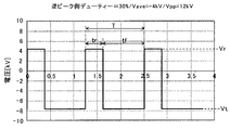
なお、低デューティーの二次転写バイアスでは、逆ピーク側デューティーの値をかなり低く設定すると、逆ピーク値Vrの絶対値が転写ピーク値Vtの絶対値よりも大きくなる。例えば、図11は、逆ピーク側デューティーが30[%]である低デューティーの二次転写バイアスにおける波形の一例を示すグラフである。また、図12は、逆ピーク側デューティーが30[%]である低デューティーの二次転写バイアスにおける波形の一例を示すグラフである。これらの二次転写バイアスにおいて、平均電位Vaveは互いに同じ−4[kV]であり、且つピークツウピーク値Vppは互いに同じ12[kV]である。そして、逆ピーク側デューティーが30[%]である図11の二次転写バイアスでは、逆ピーク値Vrの絶対値(4強)が転写ピーク値Vtの絶対値(8弱)よりも小さくなっている。これに対し、逆ピーク側デューティーが10[%]である図12の二次転写バイアスでは、逆ピーク値Vrの絶対値(7弱)が転写ピーク値Vtの絶対値(5強)よりも大きくなっている。 In the case of the secondary transfer bias having a low duty, if the value of the reverse peak side duty is set to be considerably low, the absolute value of the reverse peak value Vr becomes larger than the absolute value of the transfer peak value Vt. For example, FIG. 11 is a graph showing an example of a waveform at a low duty secondary transfer bias in which the reverse peak side duty is 30 [%]. FIG. 12 is a graph showing an example of a waveform at a low duty secondary transfer bias in which the reverse peak side duty is 30 [%]. In these secondary transfer biases, the average potential Vave is the same, -4 [kV], and the peak-to-peak value Vpp is the same, 12 [kV]. Then, with the secondary transfer bias of FIG. 11 in which the reverse peak side duty is 30 [%], the absolute value (four strong) of the reverse peak value Vr becomes smaller than the absolute value (less than eight) of the transfer peak value Vt. I have. On the other hand, with the secondary transfer bias of FIG. 12 in which the reverse peak side duty is 10%, the absolute value (slightly less than 7) of the reverse peak value Vr is larger than the absolute value (slightly more than 5) of the transfer peak value Vt. Has become.
図11の二次転写バイアスでは、逆ピーク値Vrよりも転写ピーク値Vtの方が大きい(何れも絶対値)ので、一周期内において、値を転写ピーク値Vtにしている転写ピーク側時間tfのときに二次転写ニップ内で放電を発生させて白点を引き起こし易い。これに対し、図12の二次転写場合明日では、転写ピーク値Vtよりも逆ピーク値の方が大きい(何れも絶対値)。よって、一周期内において、値を逆ピーク値Vrにしている逆ピーク側時間trのときに二次転写ニップ内で放電を発生させて白点を引き起こし易い。図11の二次転写バイアスにおける転写ピーク値Vtの絶対値(8弱)と、図12の二次転写バイアスにおける逆ピーク値Vrの絶対値(7弱)とを比較すると、後者の方が小さい。また、図12の二次転写バイアスにおける転写ピーク側時間tfと、図12の二次転写バイアスにおける逆ピーク側時間trとを比較すると、後者の方が短い。つまり、図12の二次転写バイアスの方が、図11の二次転写バイアスに比べて、白点を誘発する方のピーク値の絶対値が小さく、且つそのピーク値が持続する時間が短い。このため、図12の二次転写バイアスの方が、図11の二次転写バイアスに比べて、放電に起因する白点を引き起こし難い。よって、低デューティーの二次転写バイアスを用いて凹凸シートに画像を二次転写するときには、逆ピーク側デューティーの値をかなり小さくすることが望ましい。本発明者らの実験によれば、逆ピーク側デューティーについては、8[%]〜35[%]の範囲に設定するのが好ましく、8[%]〜17[%]の範囲に設定すると更によい結果(白点の発生を抑える)が得られた。但し、逆ピーク側デューティーをかなり小さな値にすると、一周期(T)内における逆ピーク側時間trの割合をかなり小さくしてしまう。すると、逆ピーク側時間tr内で凹凸シートの表面凹部内のトナー粒子をベルト表面に戻すことができなくなるおそれが生ずる。よって、交流成分の周波数の比較的低くして、一周期(T)を比較的長くすることで、十分な逆ピーク側時間trを確保する必要がある。 In the secondary transfer bias of FIG. 11, the transfer peak value Vt is larger than the reverse peak value Vr (both are absolute values), so that the transfer peak side time tf in which the value is set to the transfer peak value Vt in one cycle. In this case, a discharge is easily generated in the secondary transfer nip to cause white spots. On the other hand, in the case of the secondary transfer in FIG. 12, tomorrow, the reverse peak value is larger than the transfer peak value Vt (all are absolute values). Therefore, in one cycle, a discharge is generated in the secondary transfer nip at the reverse peak side time tr when the value is set to the reverse peak value Vr, so that a white point is easily caused. Comparing the absolute value (less than 8) of the transfer peak value Vt at the secondary transfer bias in FIG. 11 with the absolute value (slightly less than 7) of the reverse peak value Vr at the secondary transfer bias in FIG. 12, the latter is smaller. . Further, comparing the transfer peak side time tf in the secondary transfer bias in FIG. 12 with the reverse peak side time tr in the secondary transfer bias in FIG. 12, the latter is shorter. That is, the secondary transfer bias in FIG. 12 has a smaller absolute value of the peak value for inducing the white point and a shorter time for the peak value to be maintained, as compared with the secondary transfer bias in FIG. For this reason, the secondary transfer bias in FIG. 12 is less likely to cause white spots due to discharge than the secondary transfer bias in FIG. Therefore, when the image is secondary-transferred onto the uneven sheet using a low-duty secondary transfer bias, it is desirable that the value of the reverse peak side duty be considerably reduced. According to the experiments by the present inventors, the reverse peak side duty is preferably set in the range of 8 [%] to 35 [%], and more preferably set in the range of 8 [%] to 17 [%]. Good results (reducing the generation of white spots) were obtained. However, if the reverse peak side duty is set to a considerably small value, the ratio of the reverse peak side time tr within one cycle (T) is considerably reduced. Then, there is a possibility that the toner particles in the concave portions on the surface of the uneven sheet cannot be returned to the belt surface within the reverse peak side time tr. Therefore, it is necessary to secure a sufficient reverse peak side time tr by making the frequency of the AC component relatively low and making one cycle (T) relatively long.
ところで、本発明者らは、低デューティーの二次転写バイアスや、直流電圧だけからなる二次転写バイアスを用いる条件で、表面平滑性に優れたコート紙からなる記録シートPにハーフトーン画像を二次転写する実験を行った。すると、二次転写不良による著しい画像濃度不足をハーフトーン画像に引き起こしてしまった。 By the way, the inventors of the present invention have been able to print a halftone image on a recording sheet P made of coated paper having excellent surface smoothness under the conditions using a low duty secondary transfer bias or a secondary transfer bias consisting only of a DC voltage. An experiment for the next transfer was performed. Then, a remarkable lack of image density due to poor secondary transfer was caused in the halftone image.
このような二次転写不良を引き起こしてしまう原因について鋭意研究を行ったところ、次のようなことが判明した。即ち、ハーフトーン画像は、画像部の全てがトナーによって覆われておらず、比較的少数のドット群を構成するトナー付着箇所と、トナーを全く付着させていない空白箇所とが画像部中に混在している。弾性層31bを設けた中間転写ベルト31を用い、且つ記録シートPとして表面平滑性に優れた平滑シートを用いると、二次転写ニップ内で弾性層31bをハーフトーン画像中の少数ドット群を構成している少数ドットトナー塊の形状にならわせて柔軟に変形させる。そして、この変形により、ハーフトーン画像中の少数ドットトナー塊の表面だけでなく、少数ドットトナー塊の側面までも弾性層31bで包み込んでしまう。すると、弾性層31bから少数ドットトナー塊の各トナー粒子に正規帯電極性とは逆極性の電荷を注入させて、トナーの帯電量(Q/M)を低下させたり、トナーを逆帯電させたりする。この結果、トナー像の二次転写不良を引き起こしていることがわかった。なお、記録シートPとして、凹凸シートを用いる場合には、弾性層31bをシート表面の凹凸に応じて不規則な形状に変形させることから、弾性層31bによって少数ドットトナー塊の側面を包んでしまうことが殆どなくなる。このため、凹凸シートの表面凸部上においても、二次転写不良を引き起こすことはない。
As a result of intensive research on the cause of such secondary transfer failure, the following has been found. That is, in the halftone image, the entire image area is not covered with the toner, and a toner-adhered portion constituting a relatively small number of dot groups and a blank portion where no toner is adhering are mixed in the image portion. are doing. When the
次に、本発明者らは、二次転写バイアスとして、低デューティーのものや、直流電圧だけからなるものに代えて、図13に示される高デューティー(逆ピーク側デューティー=80%)のものを用いて、平滑シートに画像を二次転写する実験を行った。平滑シートとしては、王子製紙株式会社製のOKトップコート(128gsm)を用いた(いわゆるコート紙)。27℃/80%の環境下、プロセス線速=630[mm/s]の条件で、平滑シートにブラックハーフトーン画像(2by2)を二次転写したところ、二次転写不良を引き起こすことなく、平滑シートにブラックハーフトーン画像を良好に二次転写することができた。 Next, the present inventors use a secondary transfer bias having a high duty (reverse peak side duty = 80%) shown in FIG. 13 instead of a low duty bias or a DC voltage alone. An experiment of secondary transfer of an image to a smooth sheet was performed using the method. As a smooth sheet, OK Topcoat (128 gsm) manufactured by Oji Paper Co., Ltd. was used (so-called coated paper). When a black halftone image (2 by2) was secondarily transferred to a smooth sheet under a condition of process linear velocity = 630 [mm / s] in an environment of 27 ° C./80%, the smooth transfer was performed without causing secondary transfer failure. The black halftone image was successfully secondary-transferred to the sheet.
高デューティーの二次転写バイアスを用いることで、平滑シートに対するハーフトーン画像の二次転写性を向上させることができたのは、次に説明する理由によるものと考えられる。即ち、無端移動する中間転写ベルト31が二次転写ニップ内に進入すると、二次転写バイアスにより、二次転写ニップに進入したベルト箇所に対する充電が始まる。そして、その充電量がある閾値を超えると、ハーフトーン画像中の少数ドットトナー塊に対する逆電荷の注入が始まる。二次転写ニップに進入したベルト箇所に対する充電は、主に転写ピーク時間tf内で起こることから、この転写ピーク時間tfが長くなるほど、少数ドットトナー塊に対する逆電荷の注入量が増加する。高デューティーの二次転写バイアスは、低デューティーの二次転写バイアスに比べて、転写ピーク時間tfが短いことから、少数ドットトナー塊に対する逆電荷の注入量を低減して、二次転写不良の発生を抑えることが可能になると考えられる。
It is considered that the secondary transfer property of the halftone image on the smooth sheet could be improved by using the high duty secondary transfer bias for the following reason. That is, when the endlessly moving
なお、本発明者らによって行われた別の実験により、次のようなことも判明した。即ち、図13のように、一周期内で極性を反転させる高デューティーの二次転写バイアスよりも、図14〜図17に示されるように、極性を反転させない高デューティーの二次転写バイアスを用いる方が、平滑シートに対する二次転写性を向上させることができる。 Note that another experiment conducted by the present inventors has also revealed the following. That is, as shown in FIG. 13, a high-duty secondary transfer bias that does not invert the polarity is used, as shown in FIGS. 14 to 17, rather than a high-duty secondary transfer bias that inverts the polarity within one cycle. One can improve the secondary transfer property to the smooth sheet.
図13に示される二次転写バイアスでは、逆ピーク時間tr内において、トナーをシート表面側からベルト表面側に逆戻りさせる方向に電界の向きを反転させるように、電圧の極性を転写ピーク時間tfにおける極性とは逆極性にする。このような二次転写バイアスと、図14〜図17のように極性を反転させない二次転写バイアスとで、逆ピーク側デューティーを同じ値にし、且つ、一周期内における二次転写電界の強度積分値(Vave)を同じにして同様の二次転写性を得ようとする。すると、図13の二次転写バイアスにおける転写ピーク値Vtを、図14〜図17の二次転写バイアスにおける転写ピーク値Vtよりも大きくする必要がある。これにより、逆ピーク側デューティーや平均電位Vaveを同じにしているにもかかわらず、図13の二次転写バイアスの方が、図14〜図17の二次転写バイアスよりもハーフトーン画像の少数ドットトナー塊に対する逆電荷の注入量を増加させる。換言すると、図14〜図17の二次転写バイアスの方が、図13の二次転写バイアスに比べて転写ピーク値Vtを小さくして少数ドットトナー塊に対する逆電荷の注入量を低減することが可能なので、二次転写性をより向上させることができるのである。 In the secondary transfer bias shown in FIG. 13, the polarity of the voltage is changed during the transfer peak time tf so that the direction of the electric field is reversed within the reverse peak time tr so that the toner returns from the sheet surface side to the belt surface side. Make the polarity opposite to the polarity. With such a secondary transfer bias and the secondary transfer bias whose polarity is not inverted as shown in FIGS. 14 to 17, the reverse peak duty is set to the same value, and the intensity integration of the secondary transfer electric field within one cycle is performed. The same value (Vave) is used to obtain the same secondary transferability. Then, the transfer peak value Vt at the secondary transfer bias in FIG. 13 needs to be larger than the transfer peak value Vt at the secondary transfer bias in FIGS. As a result, the secondary transfer bias of FIG. 13 is smaller than the secondary transfer bias of FIGS. 14 to 17 in the number of dots of the halftone image, even though the reverse peak side duty and the average potential Vave are the same. Increase the amount of reverse charge injected into the toner mass. In other words, the secondary transfer bias shown in FIGS. 14 to 17 can reduce the transfer peak value Vt and reduce the amount of reverse charge injected into the small number of dot toner chunks as compared with the secondary transfer bias shown in FIG. Since it is possible, the secondary transferability can be further improved.
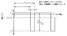
図14〜図17の二次転写バイアスは何れも、逆ピーク側デューティーが80[%]であり、且つ平均電位Vaveが−4[kV]である。但し、ピークツウピーク電位Vppが互いに異なっている。ピークツウピーク電位Vppを互いに異ならせて同じ逆ピーク側デューティー及び平均電位Vaveを実現するために、オフセット電圧Voffの値を互いに異ならせている。図14、図15、図16、図17の二次転写バイアスのピークツウピーク電位Vppは、12[kV]、10[kV]、8[kV]、6[kV]である。このようなピークツウピーク電位Vppにしていることで、図14、図15、図16、図17という図番の順で、二次転写バイアスの転写ピーク値Vtを徐々に小さくしている。一方で、図14、図15、図16、図17という順で、二次転写バイアスの逆ピーク値Vrを徐々に大きくしている。それら逆ピーク値Vrの極性は転写ピーク値Vrの極性と同じであるので、極性だけに着目すれば、逆ピーク側時間tr内においても、ハーフトーン画像の少数ドットトナー塊に対して逆電荷を注入させるおそれがある。しかしながら、図14〜図17の逆ピーク値Vrの何れにおいても、比較的低い値になっていることから、実際には、逆ピーク側時間tr内における少数ドットトナー塊に対する逆電荷の注入は殆ど起こらない。よって、少数ドットトナー塊に対する逆電荷の注入を主に引き起こす転写ピーク側時間tfにおける転写ピーク値Vtが最も高い図17の二次転写バイアスを用いると、平滑シートに対する二次転写性を最も向上させることができる。 In all of the secondary transfer biases shown in FIGS. 14 to 17, the reverse peak side duty is 80 [%] and the average potential Vave is -4 [kV]. However, the peak-to-peak potentials Vpp are different from each other. In order to realize the same reverse peak duty and average potential Vave by making the peak-to-peak potentials Vpp different from each other, the values of the offset voltages Voff are made different from each other. 14, 15, 16, and 17, the peak-to-peak potential Vpp of the secondary transfer bias is 12 kV, 10 kV, 8 kV, and 6 kV. With such a peak-to-peak potential Vpp, the transfer peak value Vt of the secondary transfer bias is gradually reduced in the order of FIG. 14, FIG. 15, FIG. 16, and FIG. On the other hand, the reverse transfer peak value Vr of the secondary transfer bias is gradually increased in the order of FIG. 14, FIG. 15, FIG. 16, and FIG. Since the polarity of the inverse peak value Vr is the same as the polarity of the transfer peak value Vr, if attention is paid only to the polarity, even within the inverse peak side time tr, the reverse charge is applied to the small number of dot toner clusters of the halftone image. May be injected. However, since the reverse peak value Vr in each of FIGS. 14 to 17 is a relatively low value, the injection of the reverse charge into the small number of dot toner lumps in the reverse peak side time tr is almost impossible. Does not happen. Therefore, by using the secondary transfer bias of FIG. 17 having the highest transfer peak value Vt at the transfer peak side time tf which mainly causes the injection of the reverse charge into the small number of toner dots, the secondary transfer property to the smooth sheet is most improved. be able to.
なお、図14〜図17の平均電位Vaveと同じ−4[kV]の直流電圧だけからなる二次転写バイアスでは、その−4[kV]という値が中間転写ベルト31から少数ドットトナー塊に対する逆電荷の注入開始の閾値を上回る。このため、一周期内で少数ドット塊に対する逆電荷の注入を常時引き起こすことから、著しい二次転写不良を引き起こしてしまう。
In the case of the secondary transfer bias consisting of only the DC voltage of -4 [kV], which is the same as the average potential Vave in FIGS. 14 to 17, the value of -4 [kV] is the inverse of the value of the
次の表1は、本発明者によって行われたプリント実験の結果を示すものである。

表1において、レザック66は、特殊東海製紙株式会社製の凹凸シートであり、坪量が大きくなるほど、表面凹部の深さが大きくなっている。つまり、表面凹部の深さの大小関係は、260kg>215kg>175kgである。また、OKトップコート(128gsm)は、王子製紙株式会社製の表面コートシート(平滑シート)である。 In Table 1, REZAC 66 is a concave and convex sheet manufactured by Tokai Tokai Paper Co., Ltd. As the grammage increases, the depth of the surface concave portion increases. That is, the relation of the depth of the surface concave portion is 260 kg> 215 kg> 175 kg. OK Topcoat (128 gsm) is a surface coated sheet (smooth sheet) manufactured by Oji Paper Co., Ltd.
このプリント実験では、凹凸シートに対しては、MとCとの重ね合わせによる青のベタ画像を二次転写する一方で、平滑シートに対しては、Kのハーフトーン画像(2by2)を二次転写した。 In this printing experiment, a solid blue image by superimposing M and C is secondarily transferred to the uneven sheet, while a halftone image (2by2) of K is secondarily transferred to the smooth sheet. Transcribed.
表1において、凹部転写性は、凹凸シートの表面凹部に対するトナーの転写性である。この凹部転写性については、凹凸シートの表面凹部における画質に基づいて評価した。ランク1からランク5までの5段階で評価し、ランク5が最も良い結果である。具体的には、表面凹部に十分量のトナーが転写されていて、表面凹部と表面凸部とで画質が殆ど変わらない場合をランク5とした。また、シート表面に存在する複数の凹部のうち、深さが最も大きい2〜3つの凹部において、Mトナー及びCトナーのうち、一方の転写量が他方に比べて僅かに少なくなったことによる僅かな色味不良が認められる場合をランク4とした。また、深さが最も大きい2〜3つの凹部において、白抜け部が認められる場合をランク3とした。また、複数の凹部において白抜け部が散見される場合をランク2とした(表1の実験結果では発生していない)。また、ほぼ全ての凹部において、白抜け部が認められる場合をランク1とした(表1の実験結果では発生していない)。
In Table 1, the recess transferability is the transferability of the toner to the recesses on the surface of the uneven sheet. The concave portion transferability was evaluated based on the image quality of the concave portions on the surface of the concave and convex sheet. Evaluation is made in five stages from
HT転写率は、平滑シートに対するKのハーフトーン画像の転写率であり、次のようにして測定した。まず、中間転写ベルト31上にハーフトーン画像を一次転写した時点でテスト機を停止させ、中間転写ベルト31上のハーフトーン画像のKトナーをバキュームによって収拾し、その重量を全重量として測定した。次に、前回と全く同じ条件で中間転写ベルト31上にハーフトーン画像を一次転写した後、すぐに平滑シートに二次転写した。この直後にテスト機を停止させ、中間転写ベルト31上に付着している転写残トナーをバキュームによって収拾し、その重量を転写残量として測定した。そして、「(全重量−転写残量)/全重量×100」の解をHT転写率として求めた。
The HT transfer rate is a transfer rate of a K halftone image to a smooth sheet, and was measured as follows. First, when the halftone image was primarily transferred onto the
マイクロゴム硬度(マイクロ硬さ)は、中間転写ベルト31から切り取ったベルト片の硬度を、高分子計器株式会社製のマイクロゴム硬度計 MD−1によって測定した値である。23℃50%の環境下において、押針をベルト片に所定の圧力で押し付けてベルト片を変形させながら、押針の押し込み深さに基づいて硬度を測定した。
The micro rubber hardness (micro hardness) is a value obtained by measuring the hardness of a belt piece cut from the
実験番号1から5までの全てにおいて、凹凸シートにベタ画像を二次転写するときには、二次転写バイアスとして、低デューティーの重畳電圧からなるものを用いた。また、実験番号1から4までにおいて、平滑シートにハーフトーン画像を二次転写するときには、二次転写バイアスとして、極性を反転させない高デューティーの重畳電圧からなるものを用いた。これに対し、実験番号5において、平滑シートにハーフトーン画像を二次転写するときには、第一実施形態とは異なり、二次転写バイアスとして直流電圧だけからなるものを用いた。
In all of Experiment Nos. 1 to 5, when a solid image was secondarily transferred to the uneven sheet, a secondary transfer bias having a low duty superimposed voltage was used. In the
実験番号1から4までの結果からわかるように、中間転写ベルト31の弾性を高めるほど(硬度を低くするほど)、凹凸シートにおける凹部転写性を向上させることができる。この一方で、弾性を高めるほど、HT転写率を低下させてしまう。凹部転写性とHT転写率とのバランスから、中間転写ベルト31のマイクロゴム硬度については、100未満にすることが望ましく、50〜80の範囲にすることがより望ましい。そこで、実施形態に係るプリンタでは、前記範囲のマイクロゴム硬度に調整した中間転写ベルト31を搭載している。
As can be seen from the results of Experiment Nos. 1 to 4, the more the elasticity of the
なお、実験番号5からわかるように、平滑シートにハーフトーン画像を二次転写するときに、二次転写バイアスとして直流電圧だけからなるものを用いると、HT転写率を著しく低下させてしまう(10%)。二次転写ニップ内で、ハーフトーン画像の少数ドットトナー塊に逆電荷を注入してしまうからである。 As can be seen from Experiment No. 5, when a halftone image is secondarily transferred to a smooth sheet, if a secondary transfer bias consisting of only a DC voltage is used, the HT transfer rate is significantly reduced (10). %). This is because in the secondary transfer nip, reverse charges are injected into a small number of dot toner blocks of the halftone image.
図18は、第一実施形態に係るプリンタの入力操作部501の電気回路を示すブロック図である。図示のように、入力操作部501は、平滑紙ボタン501aと、凹凸紙ボタン501bとを有している。第一実施形態に係るプリンタにおいては、ユーザーに対して次のような操作を行ってもらうための説明を、取り扱い説明書に記載している。即ち、給紙カセット(図1の100)に対し、記録シートPとして、コート紙などの表面平滑性に優れた高平滑シートをセットした場合には、平滑紙ボタン501aを押下する。これに対し、給紙カセットに対し、記録シートPとして、普通紙や和紙などの表面平滑性に劣る低平滑シートをセットした場合には、凹凸紙ボタン501bを押下する。つまり、入力操作部501は、次のような情報を取得することが可能な情報取得手段として機能している。即ち、トナー像の二次転写対象となる記録シートPについて、少なくとも、表面平滑性に優れた高平滑シートであるのか、あるいは高平滑シートよりも表面平滑性が劣る低平滑シートであるのかを把握することが可能な情報である。
FIG. 18 is a block diagram illustrating an electric circuit of the
制御手段としての電源制御部200は、入力操作部501による前記情報の取得結果に基づいて、高平滑シートにトナー像を二次転写するための高平滑モードと、低平滑シートにトナー像を二次転写するための低平滑モードとで転写モードを切り替える。具体的には、平滑紙ボタン501aが押下された場合には、転写モードを高平滑モードに設定する。そして、高平滑モードでは、平滑シートにハーフトーン画像を二次転写する際の少数ドットトナー塊に対する逆電荷の注入を抑えるために、高デューティーの二次転写バイアスを二次転写電源39から出力させる。その二次転写バイアスは、極性がマイナス極性で一定(反転しない)であり、且つ逆ピーク側デューティーが70[%]〜90[%]の範囲内であるという特性になっている。
The power
一方、凹凸紙ボタン501bが押下された場合には、電源制御部200は、転写モードを低平滑モードに設定する。そして、低平滑モードでは、凹凸シートの表面凹部内に十分量のトナーを二次転写するために、低デューティーの二次転写バイアスを二次転写電源39から出力させる。その二次転写バイアスは、次のような特性になっている。即ち、一周期内で極性が反転し、平均電位Vaveの極性や転写ピーク値Vtの極性が電界の向きを転写方向にするマイナス極性であり、逆ピーク値Vrの極性が電界の向きを転写方向とは逆横行にするプラス極性である。加えて、逆ピーク側デューティーが8[%]〜17[%]の範囲内であるという特性である。
On the other hand, when the
かかる構成では、記録シートとして普通紙や和紙のような低平滑シートが用いられる場合に、低デューティーの二次転写バイアスを二次転写電源39から出力することで、次のような作用効果を奏する。即ち、二次転写ニップ内において、ベルト表面と記録シートPの表面凹部内との間でトナー粒子を良好に往復移動させることで、記録シートPの表面凹部内に十分量のトナーを転移させて、表面凹凸にならった画像濃度ムラの発生を抑えることができる。また、逆ピーク側デューティーを低デューティーにすることで、放電による白点の発生を抑えることができる。
In this configuration, when a low-smooth sheet such as plain paper or Japanese paper is used as a recording sheet, the secondary
一方、記録シートとしてコート紙のような高平滑シートが用いられる場合に、高デューティーの二次転写バイアスを二次転写電源39から出力することで、次のような作用効果を奏する。即ち、逆ピーク側デューティーを高デューティーにすることで、ハーフトーン画像の少数ドットトナー群に対する逆電荷の注入を抑えて、平滑シートに対するハーフトーン画像の二次転写性を向上させる。これにより、ハーフトーン画像の画像濃度不足の発生を抑えることができる。
On the other hand, when a high-smooth sheet such as coated paper is used as the recording sheet, outputting the secondary transfer bias having a high duty from the secondary
なお、高平滑モードで高デューティーの二次転写バイアスを用いる一方で、低平滑モードで低デューティーの二次転写バイアスを用いる例について説明したが、次のようにしてもよい。即ち、高平滑モードで逆ピーク側デューティーが50[%]である二次転写バイアスを用いる一方で、低平結モードで低デューティーの二次転写バイアスを用いるようにしてもよい。また、高平滑モードで高デューティーの二次転写バイアスを用いる一方で、低平滑モードで逆ピーク側デューティーが50[%]である二次転写バイアスを用いるようにしてもよい。 Although an example in which a high-duty secondary transfer bias is used in the high-smoothing mode and a low-duty secondary transfer bias is used in the low-smoothing mode has been described, the following may be used. That is, while the secondary transfer bias having the reverse peak side duty of 50% in the high smoothing mode may be used, the secondary transfer bias having a low duty may be used in the low connection mode. Further, a secondary transfer bias having a high duty in the high smoothing mode may be used, while a secondary transfer bias having a reverse peak side duty of 50% in the low smoothing mode may be used.
次に、第一実施形態に係るプリンタにおける一部の構成を他の構成に置き換えた変形例に係るプリンタや、第一実施形態に係るプリンタに、より特徴的な構成を付加した実施例に係るプリンタについて説明する。なお、以下に特筆しない限り、変形例に係るプリンタや、実施例に係るプリンタの構成は、第一実施形態と同様である。 Next, a printer according to a modified example in which a part of the configuration of the printer according to the first embodiment is replaced with another configuration, or an example in which a more characteristic configuration is added to the printer according to the first embodiment. The printer will be described. The configuration of the printer according to the modified example and the configuration of the printer according to the example are the same as those of the first embodiment unless otherwise specified.
[変形例]
変形例に係るプリンタは、入力操作部501に、平滑紙ボタンや凹凸紙ボタンを有していない。そして、ユーザーによって記録シートの表面平滑性の情報が入力される仕様にはなっていない。その代わりに、記録シートの表面平滑性を検知する平滑性検知センサーを備えている。
[Modification]
The printer according to the modified example does not have a smooth paper button or an uneven paper button in the
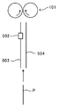
図19は、変形例に係るプリンタの給紙路を示す構成図である。給紙路は、第一案内板503と第二案内板504との間に挟み込んだ記録シートPを、レジストローラ対101のレジストニップに案内するようになっている。第一案内板503には貫通口が設けられており、この貫通口には平滑性検知センサー502が嵌め込まれている。反射型光学センサーからなる平滑性検知センサー502は、発光素子から発した光を給紙路内の記録シートPに向けて照射し、記録シートPの表面で正反射した正反射光を受光素子によって受光する。コート紙等の平滑シートの表面で得られる正反射光量は、和紙等の凹凸シートの表面で得られる正反射光量よりも多くなる。
FIG. 19 is a configuration diagram illustrating a paper feed path of a printer according to a modification. The paper feed path guides the recording sheet P sandwiched between the
平滑性検知センサー502は、電源制御部200に電気的に接続されている。電源制御部200は、プリンタの主電源が投入された直後の装置起動時に、平滑性検知センサー502の校正を実施する。具体的には、発光素子を点灯させて発光素子からの光を白色の第二案内板504の表面で反射させる状態で、所定の正反射光量が得られるように発光素子の発光量(供給電圧)を調整する。このときの供給電圧値を記憶回路に記憶しておき、以降、平滑性検知センサー502によって記録シートPの表面における正反射光量を検知するときには、記憶回路に記憶してある供給電圧値と同じ値の電圧を発光素子に供給する。
The
プリントジョブが開始されると、所定のタイミングで給紙カセット100から送り出された記録シートPは、スキュー補正のために、駆動していないレジストローラ対101のレジストニップに突き当てられて搬送が一時停止される。このとき、給紙路内において、平滑性検知センサー502に対向する。この状態で、電源制御部200は、平滑性検知センサー502により、シート表面で得られる正反射光量を検知する。そして、その検知結果が所定の閾値を上回った場合に、記録シートPを平滑シートであると判定して、上述した高平滑モードを実施する。一方、正反射光量が所定の閾値を上回らなかった場合には、記録シートPを凹凸シートであると判定して、上述した低平滑モードを実施する。
When the print job is started, the recording sheet P sent from the
かかる構成においては、二次転写ニップに搬送される記録シートPについて、平滑シート(高平滑シート)であるのか、あるいは凹凸シート(低平滑シート)であるのかを、ユーザーの操作によらずに自動で取得して、ユーザーの操作性を向上させることができる。 In such a configuration, whether the recording sheet P conveyed to the secondary transfer nip is a smooth sheet (highly smooth sheet) or an uneven sheet (low smooth sheet) is automatically determined without user operation. To improve the operability of the user.
[第一実施例]
図20は、第一実施例に係るプリンタの入力操作部501の電気回路を示すブロック図である。この入力操作部501は、第一実施形態のものとは異なり、平滑紙ボタンや凹凸紙ボタンを有していない。その代わりに、メニューキー501c、上キー501d、下キー501e、決定キー501f、ディスプレイ501gなどを有している。
[First embodiment]
FIG. 20 is a block diagram illustrating an electric circuit of the
ユーザーによってメニューキー501cが押されると、メイン制御部は、ディスプレイ501gにメニュー画面を表示させる。ユーザーは、上キー501dや下キー501eの操作により、メニュー画面に表示されている複数のメニューのうち、所望のメニューにカーソルを合わせた状態で決定キー501fを押すことで、そのメニューを選択することができる。ユーザーのキー操作により、「シート種入力」メニューが選択されると、メイン制御部は、ディスプレイ501gにシート銘柄一覧を表示させる。ユーザーは、上キー501dや下キー501eの操作により、銘柄一覧に表示されている複数の銘柄のうち、給紙カセット100にセットした記録シートと同じ銘柄を選択することができる。銘柄と、その銘柄の記録シートにおける表面平滑性とは、一対一の関係であるので、銘柄は表面平滑性を示す情報として機能し得る。
When the user presses the menu key 501c, the main control unit causes the
メイン制御部は、銘柄と、逆ピーク側デューティーの数値とを関連付けたデーターテーブルをデータ記憶回路に記憶している。その数値は、平滑シートの銘柄に対しては高デューティーの値が設定されている一方で、凹凸シートの銘柄に対しては低デューティーの値が設定されている。更に、凹凸シートの銘柄については、シート表面凹凸の度合いの大きな銘柄になるほど、逆ピーク側デューティーの数値が小さくなっている。メイン制御部は、ユーザーのメニュー操作によって銘柄が選択されると、その銘柄に対応する逆ピーク側デューティーの数値をデーターテーブルから特定する。そして、その結果を電源制御部200に送信する。電源制御部200は、メイン制御部から逆ピーク側デューティーの数値が送られてくると、以降のプリントにおいて、その数値と同じ逆ピーク側デューティーの二次転写バイアスを二次転写電源39から出力させる。これにより、平滑シートの銘柄が選択された場合には高平滑モードを実施する一方で、凹凸シートの銘柄が選択された場合には低平滑モードを実施する。
The main control unit stores a data table in which the brand and the value of the reverse peak side duty are associated with each other in the data storage circuit. As for the numerical value, a high duty value is set for the brand of the smooth sheet, while a low duty value is set for the brand of the uneven sheet. Further, as for the brand of the uneven sheet, the numerical value of the reverse peak side duty becomes smaller as the brand of the sheet surface becomes larger. When a brand is selected by a user's menu operation, the main control unit specifies the reverse peak duty value corresponding to the brand from the data table. Then, the result is transmitted to power
かかる構成では、低平滑モードにおいて、逆ピーク側デューティーの値を一定にする場合に比べて、凹凸シートの表面凸部に対するハーフトーン画像の二次転写効率を向上させたり、表面凹部に対するトナーの転写量を増加させたりすることができる。具体的には、凹凸シートは、そのシート表面凹凸の度合いが小さくなるほど、表面凸部の面積が増加して、表面凸部においてハーフトーン画像の少数ドットトナー塊に対する逆電荷の注入が起こり易くなる。この一方で、シート表面凹凸の度合いが大きくなるほど、表面凹部の大きさや深さが増加して、表面凹部へのトナーの転移不良が起こり易くなる。そこで、シート表面凹凸の度合いが大きくなるほど、逆ピーク側デューティーの値を小さくする。これにより、シート表面凹凸の度合いが比較的大きな凹凸シートであっても表面凹部に十分量のトナーを転移させることができる。加えて、シート表面凹凸の度合いが比較的小さな凹凸シートであっても表面凸部に対してハーフトーン画像部を良好に二次転写することができる。 With such a configuration, in the low smoothing mode, the secondary transfer efficiency of the halftone image to the convex portions on the surface of the uneven sheet is improved, and the transfer of the toner to the concave portions on the surface is improved as compared with the case where the value of the reverse peak side duty is fixed. Or increase the amount. Specifically, as for the uneven sheet, the smaller the degree of the sheet surface unevenness, the larger the area of the surface protrusions, and the more easily the reverse charge is injected into the small dot toner mass of the halftone image at the surface protrusions. . On the other hand, as the degree of the sheet surface irregularities increases, the size and depth of the surface recesses increase, and the poor transfer of the toner to the surface recesses easily occurs. Therefore, the value of the reverse peak side duty is reduced as the degree of the sheet surface unevenness increases. Thus, a sufficient amount of toner can be transferred to the concave portions on the surface even if the sheet has a relatively large unevenness on the sheet surface. In addition, even in the case of an uneven sheet having a relatively small unevenness on the sheet surface, the halftone image portion can be satisfactorily secondary-transferred to the convex portions on the surface.
なお、シート表面凹凸の度合いを示す指標としては、最大凹凸落差を用いることが可能である。また、最大凹凸落差を測定することが可能な測定装置の市販機としては、東京精密社製の「SURFCOM 1400D」を例示することができる。この測定装置にて、記録シート表面を顕微鏡で撮影した映像に基づいて、表面全域の中から、被検領域とする箇所をアトランダムに5つ選定する。それぞれの箇所について、評価長さ20[mm]、基準長さ20[mm]という条件で、断面曲線の最大断面高さPt(JIS B 0601:2001)を測定する。そして、得られた5つの最大断面高さPtのうち、上位3つの平均値を求める。以上の処理を、記録シートPの先端部分、中央部分、後端部分のそれぞれで実施し、それぞれの平均値の更なる平均を最大凹凸落差として求める。この最大凹凸落差(=特定情報)が例えば50[μm]以上である記録シートPを、凹凸シート(低平滑シート)とし、50[μm]未満である記録シートPを平滑シート(高平滑シート)表面凹凸シートとすればよい。 In addition, as an index indicating the degree of the sheet surface unevenness, a maximum unevenness drop can be used. Further, as a commercially available measuring device capable of measuring the maximum unevenness head, "SURFCOM 1400D" manufactured by Tokyo Seimitsu Co., Ltd. can be exemplified. With this measuring device, five locations to be tested are selected at random from the entire surface of the recording sheet based on an image of the surface of the recording sheet taken with a microscope. For each location, the maximum section height Pt (JIS B 0601: 2001) of the section curve is measured under the conditions of an evaluation length of 20 [mm] and a reference length of 20 [mm]. Then, among the obtained five maximum cross-section heights Pt, the average value of the top three is obtained. The above processing is performed on each of the leading edge portion, the central portion, and the trailing edge portion of the recording sheet P, and a further average of the respective average values is obtained as the maximum unevenness head. A recording sheet P having a maximum unevenness drop (= specific information) of, for example, 50 [μm] or more is regarded as an uneven sheet (low smooth sheet), and a recording sheet P having less than 50 [μm] is a smooth sheet (high smooth sheet). What is necessary is just to make it a surface unevenness sheet.
[第二実施例]
本発明者らは、二次転写バイアスについて、周波数、ピークツウピーク値Vpp、及び直流電圧の値(定電流制御の電流目標値)を異ならせた条件でテスト画像をプリントする実験を行った。低平滑モードでは、凹凸シートであるレザック66にKベタ画像を二次転写した。また、高平滑モードでは、平滑シートであるOKトップコート(128gsm)に青のハーフトーン画像(2by2)を二次転写した。この実験の結果を次の表2に示す。
The present inventors conducted an experiment of printing a test image under the condition that the frequency, the peak-to-peak value Vpp, and the value of the DC voltage (current target value of the constant current control) were changed for the secondary transfer bias. In the low smoothing mode, a K solid image was secondarily transferred to a REZAC 66 which is an uneven sheet. In the high smoothing mode, a blue halftone image (2by2) was secondarily transferred to an OK top coat (128 gsm) as a smooth sheet. The results of this experiment are shown in Table 2 below.
表2に示されるように、実験番号6、実験番号7の両方において、中間転写ベルト31としてマイクロゴム硬度が80であるものを用いている。表1に示した実験番号1からわかるように、このような中間転写ベルト31では、良好な凹部転写性を発揮することが可能である。但し、二次転写バイアスの特性によっては、凹部転写性を低下させるおそれもある。
As shown in Table 2, in both Experiment No. 6 and Experiment No. 7, the
実験番号6の実験においては、ピークツウピーク電位Vpp=5[kV]、周波数=1.4[kHz]、直流成分の電流目標値=−80[μA]に設定した。逆ピーク側デューティーについては、低平滑モード(凹凸紙)では13[%]、高平滑モード(平滑紙)では80[%]に設定した。 In the experiment of Experiment No. 6, the peak-to-peak potential Vpp was set at 5 [kV], the frequency was set at 1.4 [kHz], and the current target value of the DC component was set at -80 [μA]. The reverse peak side duty was set to 13 [%] in the low smoothing mode (textured paper) and 80 [%] in the high smoothing mode (smoothed paper).
実験番号7の実験においては、ピークツウピーク電位Vpp=12[kV]、周波数=0.8[kHz]、直流成分の電流目標値=−100[μA]に設定した。逆ピーク側デューティーについては、低平滑モード(凹凸紙)では13[%]、高平滑モード(平滑紙)では80[%]に設定した。 In the experiment of experiment number 7, the peak-to-peak potential Vpp was set to 12 [kV], the frequency was set to 0.8 [kHz], and the current target value of the DC component was set to -100 [μA]. The reverse peak side duty was set to 13 [%] in the low smoothing mode (textured paper) and 80 [%] in the high smoothing mode (smoothed paper).
低平滑モード(凹凸紙)に着目すると、凹部転写性は実験番号6よりも実験番号7の方が良好であった。これは次に説明する二つの理由によるものである。一つ目の理由は、周波数の違いである。低デューティーの条件下では、逆ピーク側時間trが転写ピーク側時間tfよりも短いので、凹凸シートの表面凹部内からベルト表面に向けてのトナー粒子の戻し時間が不足しがちになる。周波数が高くなるほど、その傾向が顕著になる。実験番号6では、実験番号7に比べて周波数が高いので、逆ピーク側デューティーが実験番号7と同じ13[%]であっても、逆ピーク側時間trが実験番号7よりも短くなる。これにより、凹凸シートの表面凹部内からベルト表面に十分に戻れないトナー粒子が増加して、ベルト表面上のトナー粒子の付着力を弱める作用が低減したことから、表面凹部へのトナーの転写性が悪くなったのである。 Focusing on the low-smooth mode (textured paper), the transferability of the concave portion was better in Experiment No. 7 than in Experiment No. 6. This is due to the following two reasons. The first reason is the difference in frequency. Under the condition of low duty, the reverse peak side time tr is shorter than the transfer peak side time tf, so that the time for returning the toner particles from inside the concave portions of the surface of the uneven sheet toward the belt surface tends to be insufficient. The tendency becomes more pronounced as the frequency becomes higher. In Experiment No. 6, since the frequency is higher than that in Experiment No. 7, even when the reverse peak side duty is 13 [%], which is the same as in Experiment No. 7, the reverse peak side time tr is shorter than in Experiment No. 7. This increases the amount of toner particles that cannot sufficiently return to the belt surface from within the concave portions of the uneven sheet surface, and reduces the effect of weakening the adhesion of the toner particles on the belt surface. Has become worse.
二つ目の理由は、ピークツウピーク値Vppの違いである。低デューティーの条件下では、ピークツウピーク値Vppをある程度大きな値にしないと、逆ピーク値Vrの値が不足して、凹凸シートの表面凹部内のトナー粒子をベルト表面に良好に戻せなくなる。実験番号6では、実験番号7に比べてピークツウピーク値Vppが小さくなっており、戻しピーク値Vrの値が不足気味になっているのである。 The second reason is the difference between the peak-to-peak values Vpp. Under the condition of low duty, unless the peak-to-peak value Vpp is set to a certain large value, the value of the reverse peak value Vr becomes insufficient, and the toner particles in the concave portions on the surface of the uneven sheet cannot be returned to the belt surface properly. In Experiment No. 6, the peak-to-peak value Vpp is smaller than that in Experiment No. 7, and the value of the return peak value Vr tends to be insufficient.
一方、高平滑モード(平滑紙)に着目すると、HT転写性は実験番号7よりも実験番号6が良好であった。これは、次に説明する二つの理由による。一つ目の理由は、ピークツウピーク値Vpp、及び直流成分の電流目標値の違いである。実験番号6では、ピークツウピーク値Vppが実験番号7の半分未満になっている。加えて、直流成分の電流目標値が実験番号7よりも低くなっている。これらの結果、実験番号6では、実験番号7よりも転写ピーク値Vtが小さくなっていることから、トナーに対する逆電荷の注入が起こり難くなっている。加えて、実験番号6では実験番号7とは異なり、極性がマイナス極性のまま変わらないことから、逆電荷の注入が更に起こり難くなっている。 On the other hand, when focusing on the high smoothness mode (smooth paper), HT transferability was better in Experiment No. 6 than in Experiment No. 7. This is for the following two reasons. The first reason is the difference between the peak-to-peak value Vpp and the current target value of the DC component. In Experiment No. 6, the peak-to-peak value Vpp is less than half of Experiment No. 7. In addition, the current target value of the DC component is lower than the experiment number 7. As a result, in Experiment No. 6, since the transfer peak value Vt is smaller than that in Experiment No. 7, injection of reverse charges into the toner is less likely to occur. In addition, unlike Experiment No. 7, in Experiment No. 6, since the polarity remains unchanged with the negative polarity, injection of reverse charges is further unlikely to occur.
二つ目の理由は、周波数の違いである。高平滑モードにおけるトナーへの逆電荷の注入は、上述したように、逆ピーク側時間tf内で起こる。逆ピーク側時間tfにおいては、単位時間あたりにおけるトナーへの逆電荷の注入量が経時的に増加していき、ある程度の時間が経過するとその値が飽和に達する。このため、逆ピーク側時間tfが比較的短くなると、比較的長い場合に比べて、二次転写ニップを通過する過程におけるトナーへの逆電荷の注入量が少なくなる。実験番号6では実験番号7に比べて周波数が高くなっていることから、逆ピーク側デューティーが同じ80[%]であるにもかかわらず、逆ピーク側時間tfが実験番号7よりも短くなっている。このため、実験番号7に比べてトナーへの逆電荷の注入量が少なくなっているのである。 The second reason is the difference in frequency. As described above, the injection of the reverse charge into the toner in the high smoothing mode occurs within the reverse peak side time tf. At the reverse peak side time tf, the amount of reverse charge injected into the toner per unit time increases with time, and the value reaches saturation after a certain period of time. Therefore, when the reverse peak side time tf is relatively short, the amount of reverse charge injected into the toner in the process of passing through the secondary transfer nip is smaller than when the reverse peak side time tf is relatively long. In Experiment No. 6, the frequency is higher than that in Experiment No. 7, so the reverse peak side time tf is shorter than in Experiment No. 7 even though the reverse peak side duty is the same of 80 [%]. I have. For this reason, the amount of reverse charge injected into the toner is smaller than that in Experiment No. 7.
以上の実験結果から、高平滑モードでは、低平滑モードに比べて周波数を高くすることが望ましい。これにより、高平滑モードにおいてHT転写性を向上させるとともに、低平滑モードにおいて凹部転写性を向上させることができる。 From the above experimental results, it is desirable that the frequency be higher in the high smoothing mode than in the low smoothing mode. Thereby, the HT transferability can be improved in the high smoothness mode, and the concave portion transferability can be improved in the low smoothness mode.
また、高平滑モードでは、低平滑モードに比べてピークツウピーク値Vppを低くすることが望ましい。これにより、高平滑モードにおいてHT転写性を向上させるとともに、低平滑モードにおいて凹部転写性を向上させることができる。 In the high smoothing mode, it is desirable to lower the peak-to-peak value Vpp as compared with the low smoothing mode. Thereby, the HT transferability can be improved in the high smoothness mode, and the concave portion transferability can be improved in the low smoothness mode.
なお、転写ピーク値Vtや逆ピーク値Vrを大きくし過ぎると、二次転写ニップ内でベルト表面とシート表面との間で放電を発生させ、これに起因する多数の白点を引き起こしてしまう。しかしながら、低平滑モード(凹凸紙)では、二次転写ニップ内でトナー粒子をベルト表面と凹凸シートの表面凹部との間で良好に往復移動させる必要性から、転写ピーク値Vtや逆ピーク値Vrをある程度大きな値にする必要がある。それによって僅かな白点を発生させたとしても、良好な凹部転写性が得られないよりは画像品質が良くなる。これに対し、高平滑モード(平滑紙)では、二次転写バイアスの極性を反転させてトナーを往復移動させる必要がないことから、極性を反転させない高デューティーの二次転写バイアスを用いることが可能である。これにより、HT転写性をより向上させることに加えて、転写ピーク値Vt(極性反転しないので逆ピーク値Vrよりも大きい)をより低くして白点の発生を抑えることができる。極性を反転させないようにするためには、低デューティーの二次転写バイアスに比べて、ピークツウピーク値Vpp、直流成分の電流目標値をそれぞれ小さくすればよい。 If the transfer peak value Vt or the reverse peak value Vr is too large, a discharge is generated between the surface of the belt and the surface of the sheet in the secondary transfer nip, causing many white spots. However, in the low-smooth mode (textured paper), the transfer peak value Vt and the reverse peak value Vr are required because the toner particles need to be reciprocated well between the belt surface and the concave surface of the textured sheet in the secondary transfer nip. Needs to be set to a somewhat large value. As a result, even if a slight white spot is generated, the image quality is improved as compared with the case where good concave portion transferability cannot be obtained. On the other hand, in the high-smooth mode (smooth paper), it is not necessary to invert the polarity of the secondary transfer bias to reciprocate the toner, so that a high-duty secondary transfer bias that does not invert the polarity can be used. It is. Accordingly, in addition to further improving the HT transferability, the transfer peak value Vt (which is larger than the reverse peak value Vr because the polarity is not inverted) can be further reduced to suppress the occurrence of white spots. In order to prevent the polarity from being reversed, the peak-to-peak value Vpp and the current target value of the DC component may be reduced as compared with the low duty secondary transfer bias.
そこで、電源制御部200は、
前記高平滑モードでは、前記低平滑モードに比べて周波数が高く、ピークツウピーク値Vpが低く、且つ直流電圧値(電流目標値)が大きな二次転写バイアスを二次転写電源39から出力させるようになっている。
Therefore, the
In the high smoothing mode, the secondary
次に、本発明を適用した画像形成装置として、第二実施形態に係るプリンタについて説明する。なお、第二実施形態に係るプリンタは、第一実施形態に係るプリンタに対して、より特徴的な構成を付加したものであるので、以下に特筆しない限り、第二実施形態に係るプリンタの構成は、第一実施形態と同様である。 Next, a printer according to a second embodiment will be described as an image forming apparatus to which the present invention is applied. Note that the printer according to the second embodiment is obtained by adding a more characteristic configuration to the printer according to the first embodiment. Therefore, unless otherwise specified below, the configuration of the printer according to the second embodiment will be described. Is the same as in the first embodiment.
図21は、第二実施形態に係るプリンタのシート搬送ユニット38を示す斜視図である。図22は、シート搬送ユニット38を示す正面図である。図23は、中間転写ベルト31から離間した状態のシート搬送ユニット38を示す正面図である。図24は、加圧アーム246を退避状態にしたシート搬送ユニット38を示す正面図である。
FIG. 21 is a perspective view illustrating a
これらの図において、シート搬送ユニット38は、二次転写ニップ裏打ちローラ36の回転軸両端部を回転自在に支持する加圧台46を備えている。この加圧台46は、二次転写ニップ裏打ちローラ36の回転軸に平行な加圧台回動軸43を中心にして回動可能に構成されている。
In these figures, the
加圧台46は、加圧台回動軸43よりも二次転写ニップ裏打ちローラ36が配置されている側(図中右側)で、弾性部材としての引張バネ44及び圧縮バネ45の付勢力を受けて、加圧台回動軸43回りの回転力が与えられる構成になっている。この回転力により、シート搬送ベルト41における二次転写ニップ裏打ちローラ36に対する掛け回し箇所が中間転写ベルト31に当接し、シート搬送ベルト41と中間転写ベルト31との間に二次転写ニップ圧を生じさせる。
The pressing table 46 exerts the urging force of a
加圧手段である引張バネ44は、加圧台46を上方から引っ張るように配置されており、加圧台46に対して常時ほぼ一定の付勢力を作用させるものである。一方、加圧手段である圧縮バネ45は、加圧台46を下方から押し上げるように配置されており、圧縮バネ45の下端位置が、加圧アーム246の回動角度によって上下方向に変位可能に構成されている。この加圧アーム246は、回動駆動源248によって加圧アーム回動軸247を中心に回動駆動するものである。制御部が回動駆動源248を制御することで、加圧アーム246の停止回動角度を変更することができる。
The
シート搬送ユニット38は、二次転写ニップ裏打ちローラ36の軸方向の一端側に設けられた一組の引張バネ44及び圧縮バネ45の付勢力を利用して、その一端側の加圧力を二段階で切り替えることが可能である。引張バネ44はその付勢力によってF1[N]の加圧力を常時付与する。圧縮バネ45の下端には、加圧ステー249が取り付けられており、加圧アーム246が加圧ステー249を上方に押し上げることで、圧縮バネ45による付勢力が加圧台46に作用する構成になっている。
The
加圧アーム246が図22に示されるような回動角度位置(第二回動角度)で停止した退避状態になると、圧縮バネ45の下端に取り付けられた加圧ステー249から離れて圧縮バネ45の圧縮量をゼロ(自然長)にする。すると、圧縮バネ45の付勢力が加圧台46に作用しなくなることから、上記一端側の加圧力が引張バネ44の付勢力だけによるF1[N]になる。加圧アーム246が図22に示される第二回動角度で停止したときの上記一端側の加圧力は、単位圧縮量または単位引張量に対する復元力の変化率が圧縮バネ45よりも小さい引張バネ44による付勢力だけで実現される。このため、目標の二次転写ニップ圧を得やすいという利点がある。
When the
一方、加圧アーム246が図24に示される回動角度位置(第一回動角度)で停止した圧縮バネ加圧状態になると、圧縮バネ45の下端に取り付けられた加圧ステー249を押し上げる。これにより、圧縮バネ45を圧縮して、圧縮バネ45の付勢力を加圧台46に作用させる。すると、圧縮バネ45の付勢力によってF2[N]の加圧力が加圧台46に付与され、上記一端側の加圧力が引張バネ44の付勢力によるF1[N]と圧縮バネ45の付勢力によるF2[N]との合算値であるF3[N]になる。
On the other hand, when the
上記一端側の加圧アーム246について説明したが、他端側の加圧アーム246も同様に、加圧力をF1[N]とF3[N]とで切り替える。2つの加圧アーム246がそれぞれ加圧力を切り替えることで、二次転写ニップ圧は2×F1[N]と2×F3[N]とで切り替わる。
Although the
引張バネ44としては、1.3[N/mm]のバネ定数をもつバネ部材を例示することができる。また、圧縮バネ45としては、2.6[N/mm]のバネ定数をもつバネ部材を例示することができる。
As the
シート搬送ユニット38は、中間転写ベルト31のおもて面に対してシート搬送ベルト41を当接させる当接位置から、離間させる離間位置に移動させる移動手段として、離間アーム251を有している。この離間アーム251は、離間レバーの操作に連動して、離間アーム回動軸252を中心に回動するものである。離間レバーの操作により、離間アーム251の停止回動角度位置を切り替えることができる。
The
離間アーム251は、その自由端部側部分を加圧台46の上面側に位置させるように配置されている。画像形成動作時においては、図22に示されるように、加圧台46を押し下げない回動角度位置で離間アーム251が停止している。すると、二次転写ニップ裏打ちローラ36が中間転写ベルト31に当接する当接位置に拘束される。
The
一方、二次転写ユニット41の交換等のメンテナンス処理時やジャム処理時には、作業者が離間レバーを操作することで、離間アーム251を図23に示される回動角度位置に移動させる。すると、離間アーム251の自由端部側部分が加圧台46の上面に当接し、引張バネ44の付勢力に抗して加圧台46を押し下げる。これにより、加圧台46が加圧台回動軸43回りで回動して、図23に示されるように、二次転写ニップ裏打ちローラ36が中間転写ベルト31から離間する離間位置に移動する。この離間により、メンテナンス処理やジャム処理の作業を実施し易くする。
On the other hand, at the time of maintenance processing such as replacement of the
加圧アーム246は、上述した退避状態であるとき、離間レバーに連動した離間アーム251により加圧台回動軸43回りで回動する加圧台46の回動範囲(移動経路)外に位置している。加圧アーム246が加圧台46の回動範囲外に位置していることにより、加圧アーム246に邪魔されることなく、二次転写ニップ裏打ちローラ36が当接位置から離間位置に移動することができる。
The
無端状のシート搬送ベルト41は、二次転写ニップ裏打ちローラ36、分離ローラ46、二次転写第一張架ローラ362及び二次転写第二張架ローラ363の四つのローラによって張架されている。これら四つのローラは、上述した転写ユニット30に支持されており、転写ユニット30を加圧台46から取り外すことで、四つのローラとともにシート搬送ベルト41を加圧台46から取り外すことができる。
The endless
加圧台46は、二次転写ニップ裏打ちローラ36の軸方向(図21中Y軸方向)両端をそれぞれ支持し、二次転写ニップ裏打ちローラ36の加圧台46に対する位置を位置決めする前側板461と後側板462とを備えている。二つの側板(461、462)は、図21中のY軸方向に延在する規制手段としての回動軸側ステー部材464と、変位可能規制手段としての加圧側上ステー部材463との二つのステー部材を介して繋がっている。
The pressing table 46 supports both ends of the secondary transfer nip lining
加圧台46は、前側板461と、後側板462と、回動軸側ステー部材464と、加圧側上ステー部材463とにより、上方からの眺めが(図中のX−Y平面で)略長方形状となる構造体を構成している。前側板461は、前側板軸受部461aで二次転写ニップ裏打ちローラ36の軸方向の手前側端部を回転可能に支持している。また、後側板462は、後側板軸受部462aで二次転写ニップ裏打ちローラ36の軸方向の奥側端部を回転可能に支持している。
The press table 46 has a view from above (in the XY plane in the figure) of the
図21に示される回動軸側ステー部材464は板金からなり、軸方向(Y軸方向)両端付近が直角に折り曲げられて、それぞれ側板461、462に対向する対向面を形成している。これら対向面を、それぞれ側板461,462に固定することで、各側板の回転軸側が、回動軸側ステー部材464によって側板同士の軸方向(Y軸方向)の相対的な移動規制をなされる。また、回動軸側ステー部材464の軸方向両端部の側板461,462に対向する対向面が側板461,462に固定されていることで、各側板を補強している。このように、回動軸側ステー部材464の軸方向両端部の側板461,462に対向する対向面が、各側板461,462を補強する。
The rotation shaft
第二実施形態に係る複写機においては、シート搬送ユニット38が二次転写ニップの圧力を変更するニップ圧変更手段として機能している。
In the copying machine according to the second embodiment, the
本発明者らは、第二実施形態に係る複写機のシート搬送ユニット38と同様にして、二次転写ニップの圧力を二段階に変化させることが可能なプリンタ試験機を用意した。そして、このプリンタ試験機を用いて、二色重ね合わせのブルーベタ画像を表面凹凸シートにプリントする実験を行った。
The present inventors have prepared a printer tester capable of changing the pressure of the secondary transfer nip in two steps in the same manner as the
表面凹凸シートとしては、レザック66(175kg)、レザック66(215kg)の二種類を用いた。坪量が高い方が、表面凹部の深さが大きくなっている。実験室の環境については、温度23[℃]、湿度50[%]に維持した。また、プロセス線速については、630[mm/s]に設定した。二次転写バイアスとしては、次に掲げる二種類を採用した。
・直流電圧を−120[μA]の出力電流目標値で定電流制御したもの(DC)。
・直流電圧を−120[μA]の出力電流目標値で定電流制御したもの(DC)に対して、ピークツウピーク値Vpp=9[kV]、デューティー=12[%]の低デューティーの交流電圧(AC)を重畳した重畳電圧からなるもの。
Two types of REZAC 66 (175 kg) and REZAC 66 (215 kg) were used as the uneven surface sheet. The higher the grammage, the greater the depth of the surface recess. The laboratory environment was maintained at a temperature of 23 ° C. and a humidity of 50%. Further, the process linear velocity was set to 630 [mm / s]. As the secondary transfer bias, the following two types were employed.
-A DC voltage that is controlled by a constant current at an output current target value of -120 [μA] (DC).
A low-duty AC voltage with a peak-to-peak value Vpp = 9 [kV] and a duty ratio of 12 [%] with respect to a DC voltage obtained by performing a constant current control with an output current target value of -120 [μA] (DC). (AC) is composed of a superimposed voltage.
二次転写ニップ圧については、高、中、低の三段階に変化させた。プリンタ試験機は、上述したように、二次転写ニップ圧を二段階でしか変化させることができないことから、圧縮バネ45をバネ定数の異なるものに変更することで、二次転写ニップ圧を三段階に変化させた。
The secondary transfer nip pressure was changed in three steps: high, medium, and low. Since the printer tester can change the secondary transfer nip pressure only in two steps as described above, by changing the
表面凹凸シートにプリントしたブルーベタ画像については、シート表面凹部へのトナー転写性(凹部転写性)のランクを評価した。具体的には、目視にて、シート表面凹部内に対して十分量のトナーを転移させていることから、凹部上において十分な画像濃度が得られている場合をランク5として評価した。また、凹部内のごく僅かな領域を白く抜けた領域にしているか、あるいは、凹部の画像濃度が平滑部よりも僅かに低い状態になっている場合を、ランク4として評価した。また、ランク4よりも、白抜けの領域が大きい場合、あるいは濃度低下が目立つ場合を、ランク3として評価した。また、ランク3に比べ、さらに白抜けの領域が大きい場合、あるいは濃度低下が目立つ場合をランク2として評価した。また、凹部が全体的に白く、全体的に溝の状態がはっきりと認識できる場合や、さらに悪い場合をランク1として評価した。
With respect to the blue solid image printed on the uneven surface sheet, the rank of the toner transferability (recess transferability) to the concave portion on the sheet surface was evaluated. Specifically, since a sufficient amount of toner was transferred to the inside of the concave portion on the sheet surface by visual observation, a case where a sufficient image density was obtained on the concave portion was evaluated as
この実験の結果を次の表3に示す。
表3に示されるように、直流電圧だけからなる二次転写バイアスを用いると、低デューティーの重畳電圧からなる二次転写バイアスを用いる場合に比べて、凹部転写性のランクを悪くしてしまう。 As shown in Table 3, when the secondary transfer bias including only the DC voltage is used, the rank of the concave portion transferability is deteriorated as compared with the case where the secondary transfer bias including the low duty superimposed voltage is used.
同じ二次転写ニップ圧に着目して、レザック66の坪量の違いで凹部転写性のランクを比較してみると、両者には際だった差が認められないことがわかる。215kgの方が175kgよりも凹部の深さが大きいので、当然ながら凹部転写性が悪くなるが、表3に示されるように、ピークツウピーク値Vppをより大きくすることで、凹部転写性を向上させてランクを同等の値にすることができている。但し、ピークツウピーク値Vppを大きくし過ぎると、転写ピーク値Vtをベルト表面とシート表面との間の放電開始電圧よりも大きくして二次転写ニップ内で放電を多発させ、それによる多数の白点を発生させてしまう。このため、それら多数の白点は、凹部へのトナー転写不良よりも画質を悪化させるので、多数の白点を発生させない値に、ピークツウピーク値Vppを留める必要がある。 Focusing on the same secondary transfer nip pressure and comparing the ranks of the concave transferability with the difference in the basis weight of REZAC 66, it can be seen that there is no remarkable difference between the two. Since the depth of the concave portion is larger in the case of 215 kg than in the case of 175 kg, the transferability of the concave portion is naturally deteriorated. However, as shown in Table 3, the transferability of the concave portion is improved by increasing the peak-to-peak value Vpp. By doing so, the ranks can be set to the same value. However, if the peak-to-peak value Vpp is too large, the transfer peak value Vt is made larger than the discharge starting voltage between the belt surface and the sheet surface to cause a large number of discharges in the secondary transfer nip. White spots are generated. For this reason, the large number of white points deteriorates the image quality more than the poor transfer of the toner to the concave portion. Therefore, it is necessary to keep the peak-to-peak value Vpp at a value that does not generate a large number of white points.
一方、同じ種類の表面凹凸シートに着目して、二次転写ニップ圧の違いで凹部転写性のランクを比較してみると、二次転写ニップ圧を高くするほど、ランクを向上させていることがわかる。二次転写ニップ圧を高くするほど、シート表面凹部と、中間転写ベルト31表面との密着性を高めるからである。よって、凹部転写性の観点からすれば、二次転写ニップ圧については、比較的高く設定することが望ましい。
On the other hand, focusing on the same type of surface unevenness sheet, comparing the ranks of concave transferability with the difference in secondary transfer nip pressure, the higher the secondary transfer nip pressure, the higher the rank I understand. This is because the higher the secondary transfer nip pressure is, the higher the adhesiveness between the sheet surface concave portion and the surface of the
次に、発明者らは、プリンタ試験機を用いて、K一色のハーフトーン画像を平滑シートにプリントする実験を行った。 Next, the inventors conducted an experiment of printing a K-color halftone image on a smooth sheet using a printer tester.
平滑シートとしては、表面コート紙である「Mohawk Color Copy Gloss 270gsm」を用いた。実験室の環境については、温度23[℃]、湿度50[%]に維持した。また、プロセス線速については、630[mm/s]に設定した。二次転写ニップ圧については、先の実験と同様に、高、中、低の三段階を採用した。 As the smooth sheet, “Mohawk Color Copy Gloss 270 gsm” which is a surface-coated paper was used. The laboratory environment was maintained at a temperature of 23 ° C. and a humidity of 50%. Further, the process linear velocity was set to 630 [mm / s]. Regarding the secondary transfer nip pressure, three steps of high, middle, and low were adopted as in the previous experiment.
二次転写バイアスとしては、次に掲げる二種類を採用した。
・直流電圧を−120[μA]の出力電流目標値で定電流制御したもの(DC)。
・直流電圧を−120[μA]の出力電流目標値で定電流制御したもの(DC)に対して、ピークツウピーク値Vpp=6.4[kV]、デューティー=85[%]の高デューティーの交流電圧(AC)を重畳した重畳電圧からなるもの。
As the secondary transfer bias, the following two types were employed.
-A DC voltage that is controlled by a constant current at an output current target value of -120 [μA] (DC).
-Higher duty of peak-to-peak value Vpp = 6.4 [kV] and duty = 85 [%] with respect to DC voltage (DC) which is constant current controlled with an output current target value of -120 [μA] It consists of a superimposed voltage on which an alternating voltage (AC) is superimposed.
平滑シートにプリントしたハーフトーン画像については、その転写性(HT転写性)のランクを評価した。具体的には、目視にて、十分なハーフトーンの濃度が得られている状態をランク5と評価した。また、ランク5に比べてやや薄いが、問題のない濃さが得られている状態をランク4として評価した。また、ランク4に比べてさらに薄く、ユーザーに提供する画質としては問題となる状態をランク3として評価した。また、ランク3に比べてさらに薄い状態をランク2として評価した。また、全体的に白っぽい場合やそれよりも薄い状態をランク1として評価した。ユーザーに提供できる画質の許容レベルは、ランク4以上である。
About the halftone image printed on the smooth sheet, the rank of the transferability (HT transferability) was evaluated. Specifically, a state in which a sufficient halftone density was obtained was visually evaluated as
この実験の結果を次の表4に示す。
表4に示されるように、直流電圧だけからなる二次転写バイアスを用いると、高デューティーの重畳電圧からなる二次転写バイアスを用いる場合に比べて、HT転写性のランクを悪くしてしまう。 As shown in Table 4, when the secondary transfer bias including only the DC voltage is used, the rank of the HT transferability is deteriorated as compared with the case where the secondary transfer bias including the high duty superimposed voltage is used.
二次転写ニップ圧の違いでHT転写性のランクを比較してみると、表面凹凸シートにおける凹部転写性とは逆に、二次転写ニップ圧を高くするほど、ランクを悪化させていることがわかる。二次転写ニップ圧を高くするほど、シート平滑面上のトナー塊を弾性変形した中間転写ベルト31で包み込む面積を増加させて、トナーへの逆電荷の注入量を増加させてしまうからである。よって、平滑シートにおけるHT転写性の観点からすれば、二次転写ニップ圧については、比較的低く設定することが望ましい。
Comparing the HT transferability ranks based on the difference in the secondary transfer nip pressure, the higher the secondary transfer nip pressure is, the worse the rank is, contrary to the concave transferability of the uneven surface sheet. Understand. This is because, as the secondary transfer nip pressure is increased, the area in which the toner mass on the smooth surface of the sheet is wrapped by the elastically deformed
以上の実験結果に鑑みて、第二実施形態に係るプリンタにおいては、低平滑モードでは、高平滑モードに比べて、二次転写ニップ圧を高くする制御を実施するように、後述するメイン制御部を構成している。かかる構成においては、低平滑モードでは二次転写ニップ圧を比較的高くして凹部転写性の向上を図る一方で、高平滑モードでは二次転写ニップ圧を比較的低くしてHT転写性の向上を図ることができる。 In view of the above experimental results, in the printer according to the second embodiment, in the low smoothing mode, a main control unit (described later) performs control to increase the secondary transfer nip pressure in comparison with the high smoothing mode. Is composed. In such a configuration, in the low smoothing mode, the secondary transfer nip pressure is set relatively high to improve the concave portion transferability, while in the high smoothing mode, the secondary transfer nip pressure is set relatively low to improve the HT transferability. Can be achieved.
図25は、第二実施形態に係るプリンタの電気回路の一部を示すブロック図である。同図において、二次転写電源39からの二次転写バイアスの出力を制御する電源制御部200には、プリンタの各機器の駆動を制御するメイン制御部350が接続されている。入力操作部501に入力された情報は、入力操作部501から電源制御部200に送信されるとともに、メイン制御部350にも送信される。
FIG. 25 is a block diagram showing a part of the electric circuit of the printer according to the second embodiment. In the figure, a
メイン制御部350は、低平滑モードにおいて、ニップ圧変更手段としてのシート搬送ユニット38を制御して、二次転写ニップ圧をF3[N]にする。これにより、表面凹凸シートの表面凹部内の深い位置まで、トナーを良好に転位させて表面凹部で非常に良いトナー転写性を得るようにする。一方、高平滑モードでは、シート搬送ユニット38を制御して、二次転写ニップ圧をF1[N]にする。これにより、HT転写性をより向上させることができる。
In the low smoothing mode, the
なお、第二実施形態に係るプリンタに対し、上述した変形例、第一実施例、又は第二実施例の構成を付加してもよい。 Note that the configuration of the above-described modification, the first embodiment, or the second embodiment may be added to the printer according to the second embodiment.
以上に説明したものは一例であり、次の態様毎に特有の効果を奏する。
[態様A]
態様Aは、直流電圧と交流電圧との重畳による重畳電圧からなる転写バイアス(例えば二次転写バイアス)を転写電源(例えば二次転写電源39)から出力して、像担持体(例えば中間転写ベルト31)とニップ形成部材(例えばシート搬送ベルト41)との当接による転写ニップ(例えば二次転写ニップ)に転写電流(例えば二次転写電流)を流しながら、前記像担持体の表面上のトナー像を前記転写ニップに挟み込んだ記録シートに転写する画像形成装置(例えばプリンタ)において、トナー像の転写対象となる記録シートの表面平滑性に関する情報を取得する情報取得手段(例えば入力操作部501や平滑性検知センサー502)と、前記情報取得手段による前記情報の取得結果に基づいて、表面平滑性に優れた高平滑シートにトナー像を転写するための高平滑モードと、前記高平滑性シートよりも表面平滑性に劣る低平滑シートにトナー像を転写するための低平滑モードとで転写モードを切り替え、前記高平滑モードでは、前記転写バイアスにおける二つのピーク値のうち、前記転写ニップ内でトナーを像担持体側からニップ形成部材側により強く静電移動させる方の転写ピーク値とは逆のピーク値の側におけるデューティーである逆ピーク側デューティーが50[%]以上である転写バイアスを前記転写電源から出力させる一方で、前記低平滑モードでは逆ピーク側デューティーが前記高平滑モードとは異なる値であって且つ50[%]以下である転写バイアスを前記転写電源から出力させる制御手段(例えば電源制御部200)とを設けたことを特徴とするものである。
What has been described above is merely an example, and each embodiment has a specific effect.
[Aspect A]
In the embodiment A, a transfer bias (for example, a secondary transfer bias) composed of a superimposed voltage obtained by superimposing a DC voltage and an AC voltage is output from a transfer power supply (for example, the secondary transfer power supply 39), and an image carrier (for example, an intermediate transfer belt) is output. 31), while applying a transfer current (for example, a secondary transfer current) to a transfer nip (for example, a secondary transfer nip) caused by contact between the nip forming member (for example, the sheet conveying belt 41) and the toner on the surface of the image carrier. In an image forming apparatus (for example, a printer) for transferring an image to a recording sheet sandwiched between the transfer nips, an information acquiring unit (for example, an
かかる構成において、像担持体として柔軟性のあるものを用いれば、転写ニップ内における像担持体表面と低平滑シートの表面との密着性を高めて、像担持体表面と低平滑シートの表面凹部の底面との距離を小さくすることが可能になる。このように距離を小さくすることで、事業ユース向けの要望に応え得るほどの高速プリント化を図っても、低平滑シートの表面凹部に対してもトナーを良好に転写することが可能になる。但し、その良好な転写を実現するために、転写バイアスの交流電圧のピークツウピーク値を高くし過ぎると、転写ニップ内で放電を多発させて、放電に起因する多数の白点を画像中に発生させてしまう。この一方で、記録シートとして、表面平滑性に優れた高平滑シートを用いると、転写ニップ内でトナーに対して逆電荷を注入してトナー像の転写不良を引き起こし易くなってしまう。 In such a configuration, if a flexible image carrier is used, the adhesion between the surface of the image carrier and the surface of the low-smooth sheet in the transfer nip is increased, and the surface recesses of the image carrier and the low-smooth sheet are reduced. Can be reduced in distance from the bottom surface. By reducing the distance in this way, it is possible to transfer the toner satisfactorily even to the concave portions on the surface of the low-smooth sheet, even if high-speed printing is performed to meet the demand for business use. However, if the peak-to-peak value of the AC voltage of the transfer bias is set too high in order to realize the good transfer, the discharge occurs frequently in the transfer nip, and a large number of white spots due to the discharge appear in the image. Cause it to occur. On the other hand, when a highly smooth sheet having excellent surface smoothness is used as a recording sheet, a reverse charge is injected into the toner in the transfer nip, so that a transfer failure of the toner image is easily caused.
そこで、態様Aでは、低平滑シートに対しては、逆ピーク側デューティーを高平滑シートが用いられる場合とは異なる値であって且つ50[%]以下にした転写バイアスを用いてトナー像を転写する。これにより、逆ピーク側デューティーを50[%]よりも大きくする場合に比べて、より小さいピークツウピーク値の転写バイアスで表面凹部に十分量のトナーを転写することが可能になる。よって、低平滑シートにおける表面凹部へのトナーの転写不良や画像中の白点の発生を抑えることができる。一方、高平滑シートに対しては、逆ピーク側デューティーを、低平滑シートが用いられる場合とは異なる値であって且つ50[%]以上にしたものを用いる。これにより、逆ピーク側デューティーを50[%]未満にする場合に比べて、転写ニップ内のトナーに対する逆電荷の注入を抑えることで、高平滑シートに対するトナー像の転写不良の発生を抑えることができる。 Therefore, in the embodiment A, the toner image is transferred to the low-smooth sheet using a transfer bias having a reverse peak side duty different from that in the case where the high-smooth sheet is used and 50% or less. I do. This makes it possible to transfer a sufficient amount of toner to the concave portions on the surface with a transfer bias having a smaller peak-to-peak value as compared with the case where the reverse peak side duty is made larger than 50 [%]. Therefore, it is possible to suppress the poor transfer of the toner to the concave portions on the surface of the low-smooth sheet and the occurrence of white spots in the image. On the other hand, for a high smooth sheet, a sheet having a reverse peak side duty different from that when a low smooth sheet is used and having a duty of 50% or more is used. Thus, compared to the case where the reverse peak side duty is set to less than 50%, the injection of the reverse charge into the toner in the transfer nip is suppressed, thereby suppressing the occurrence of the transfer failure of the toner image to the highly smooth sheet. it can.
以上のように、態様Aにおいては、高速プリント化を図りつつ、低平滑シートにおける表面凹部へのトナーの転写不良や画像中の白点の発生を抑え、且つ高平滑シートに対するトナー像の転写不良の発生を抑えることができる。 As described above, in the embodiment A, while achieving high-speed printing, it is possible to suppress poor transfer of the toner to the concave portions on the surface of the low-smooth sheet and the occurrence of white spots in the image, and to transfer the toner image to the high-smooth sheet Can be suppressed.
[態様B]
態様Bは、態様Aにおいて、前記転写ニップの圧力を変更するニップ圧変更手段(例えばシート搬送ユニット38)を設け、前記低平滑モードでは、前記高平滑モードに比べて前記圧力を高くする制御を前記ニップ圧変更手段に対して行うように、前記制御手段(例えば電源制御部200及びメイン制御部350の組み合わせ)を構成したことを特徴とするものである。かかる構成においては、低平滑モードでは転写ニップ圧を比較的高くして凹凸シートの表面凹部に対するトナー転写性の向上を図る一方で、高平滑モードでは二次転写ニップ圧を比較的低くして平滑シートの平滑面に対する画像転写性の向上を図ることができる。
[Aspect B]
In a mode B, a nip pressure changing unit (for example, a sheet conveying unit 38) for changing the pressure of the transfer nip is provided in the mode A, and the control for increasing the pressure in the low smoothing mode is higher than that in the high smoothing mode. The control unit (for example, a combination of the power
[態様C]
態様Cは、態様A又はBにおいて、前記高平滑モードでは逆ピーク側デューティーが50[%]を超える転写バイアスを前記転写電源から出力させる一方で、前記低平滑モードでは一周期内で極性が反転し且つ逆ピーク側デューティーが50[%]未満である転写バイアスを前記転写電源から出力させる制御を実施するように、前記制御手段を構成したことを特徴とするものである。かかる構成では、高平滑モード又は低平滑モードの何れか一方において、逆ピーク側デューティーが50[%]であるものを用いる場合に比べて、次のような作用効果を奏することができる。即ち、低平滑シートの表面凹部に対するトナーの転移性を向上させたり、高平滑シートに対するトナー像の転写不良をより抑えたりすることができる。
[Aspect C]
In the aspect C, in the aspect A or B, the transfer bias in which the reverse peak side duty exceeds 50 [%] is output from the transfer power supply in the high smoothing mode, while the polarity is inverted within one cycle in the low smoothing mode. And the control unit is configured to execute a control for outputting a transfer bias having a reverse peak side duty of less than 50 [%] from the transfer power supply. With such a configuration, the following operation and effect can be achieved as compared with a case where the reverse peak side duty is 50% in either the high smoothing mode or the low smoothing mode. That is, the transferability of the toner to the concave portions on the surface of the low smooth sheet can be improved, and the transfer failure of the toner image to the high smooth sheet can be further suppressed.
[態様D]
態様Dは、態様Cにおいて、前記高平滑モードでは、逆ピーク側デューティーが70[%]〜90[%]の範囲である転写バイアスを前記転写電源から出力させる制御を実施するように、前記制御手段を構成したことを特徴とするものである。かかる構成では、高平滑シートに対するトナー像の転写不良の発生をより確実に抑えることができる。
[Aspect D]
In the aspect D, in the aspect C, in the high smoothing mode, the control is performed such that a transfer bias having a reverse peak side duty in a range of 70 [%] to 90 [%] is output from the transfer power supply. It is characterized by comprising means. With such a configuration, it is possible to more reliably suppress the occurrence of transfer failure of the toner image to the highly smooth sheet.
[態様E]
態様Eは、態様B又はCにおいて、前記低平滑モードでは、逆ピーク側デューティーが8[%]〜35[%]の範囲である転写バイアスを前記転写電源から出力させる制御を実施するように、前記制御手段を構成したことを特徴とするものである。かかる構成では、低平滑シートの表面凹部に対して十分量のトナーを確実に転写することができる。
[Aspect E]
In the aspect E, in the aspect B or C, in the low smoothing mode, control is performed such that a transfer bias having a reverse peak side duty in a range of 8 [%] to 35 [%] is output from the transfer power supply. It is characterized by comprising the control means. With this configuration, it is possible to reliably transfer a sufficient amount of toner to the concave portions on the surface of the low-smooth sheet.
[態様F]
態様Fは、態様Eにおいて、前記低平滑モードでは、逆ピーク側デューティーが17[%]以下である転写バイアスを前記転写電源から出力させる制御を実施するように、前記制御手段を構成したことを特徴とするものである。かかる構成では、低平滑シートの表面凹部に対するトナー転写性を更に向上させることができる。
[Aspect F]
In an aspect F, the control means is configured to execute the control of outputting the transfer bias having the reverse peak side duty of 17% or less from the transfer power supply in the low smoothing mode in the aspect E. It is a feature. With such a configuration, it is possible to further improve the toner transferability to the concave portions on the surface of the low-smooth sheet.
[態様G]
態様Gは、態様C〜Fの何れかにおいて、前記高平滑モードでは、極性を変化させない転写バイアスを前記転写電源から出力させる制御を実施するように、前記制御手段を構成したことを特徴とするものである。かかる構成では、二次転写バイアスの極性を一周期内で反転させる場合に比べて、高平滑シートに対する二次転写不良の発生をより確実に抑えることができる。
[Aspect G]
In a mode G, in any one of modes C to F, in the high smoothing mode, the control unit is configured to perform control of outputting a transfer bias that does not change the polarity from the transfer power supply in the high smoothing mode. Things. With this configuration, it is possible to more reliably suppress the occurrence of secondary transfer failure on a highly smooth sheet as compared with a case where the polarity of the secondary transfer bias is reversed within one cycle.
[態様H]
態様Hは、態様A〜Gの何れかにおいて、前記像担持体として、前記基層(例えば基層31a)の上にこれよりも弾性に優れた弾性層(例えば弾性層31b)が積層された多層構造のものを用いたことを特徴とするものである。かかる構成では、転写ニップ内で弾性層を柔軟に変形させることで、低平滑シートの表面凹部に対するトナーの転移性を高めて、事業ユース向けの要望に応え得るほどの高速プリント化を図ることができる。
[Aspect H]
Aspect H is a multilayer structure according to any one of Aspects A to G, in which an elastic layer (e.g.,
[態様I]
態様Iは、態様Hにおいて、前記像担持体として、マイクロゴム硬度が50〜80であるものを用いたことを特徴とするものである。かかる構成では、転写ニップ内で弾性層をトナー塊に形状にならわせて良好且つ柔軟に変形させることができる。
[Aspect I]
Embodiment I is the embodiment H, wherein the image carrier having a micro rubber hardness of 50 to 80 is used. In such a configuration, the elastic layer can be satisfactorily and flexibly deformed in the transfer nip by forming the elastic layer into the shape of the toner mass.
[態様J]
態様Jは、態様A〜Iの何れかにおいて、前記情報取得手段として、記録シートの表面平滑性を検知する平滑性検知手段(例えば平滑性検知センサー502)を用い、前記平滑性検知手段による検知結果に基づいて、転写モードを前記高平滑モードと前記低平滑モードとで切り替える制御を実施するように、前記制御手段を構成したことを特徴とするものである。かかる構成では、トナー像の転写対象となる記録シートについて、高平滑シートであるのか、あるいは低平滑シートであるのかを、ユーザーの操作によらずに自動で取得して、操作性を向上させることができる。
[Aspect J]
In the aspect J, in any one of the aspects A to I, a smoothness detecting means (for example, a smoothness detecting sensor 502) for detecting a surface smoothness of the recording sheet is used as the information acquiring means, and the information is detected by the smoothness detecting means. The control means is configured to execute control for switching a transfer mode between the high smoothing mode and the low smoothing mode based on a result. With such a configuration, the operability can be improved by automatically acquiring whether the recording sheet to which the toner image is to be transferred is a high smooth sheet or a low smooth sheet without depending on a user operation. Can be.
[態様K]
態様Kは、態様A〜Iの何れかにおいて、前記情報取得手段として、ユーザーによる前記情報の入力操作がなされる入力操作手段(例えば入力操作部501)を用いたことを特徴とするものである。かかる構成では、ユーザーの操作により、トナー像の転写対象となる記録シートについて、高平滑シートであるのか、あるいは低平滑シートであるのかを取得することができる。
[Aspect K]
Embodiment K is characterized in that in any one of Embodiments A to I, an input operation unit (for example, an input operation unit 501) on which a user performs an input operation of the information is used as the information acquisition unit. . With this configuration, it is possible to acquire whether the recording sheet to which the toner image is to be transferred is a high smooth sheet or a low smooth sheet by a user operation.
[態様L]
態様Lは、態様Kにおいて、記録シートについて前記高平滑シートである旨の情報を入力するための専用の入力部(例えば平滑紙ボタン501a)と、前記低平滑シードである旨の情報を入力するための専用の入力部(例えば凹凸紙ボタン501b)とを前記入力操作手段に設けたことを特徴とするものである。かかる構成では、それぞれ専用の入力部を設けたことで、ユーザーの入力操作性を向上させることができる。
[Aspect L]
In an aspect L, in the aspect K, a dedicated input section (for example, a
[態様M]
態様Mは、態様Kにおいて、記録シートの銘柄情報を入力することが可能な銘柄入力部を前記入力操作手段に設け、前記低平滑モードでは、前記銘柄入力部に入力される銘柄情報がシート表面凹凸の度合いの大きな銘柄になるほど、逆ピーク側デューティーの低い転写バイアスを前記転写電源から出力させる制御を実施するように、前記制御手段を構成したことを特徴とするものである。かかる構成では、低平滑モードにおいて、シート表面凹凸の度合いが比較的大きな凹凸シートであっても表面凹部に十分量のトナーを転移させることができる。加えて、シート表面凹凸の度合いが比較的小さな凹凸シートであっても表面凸部に対してハーフトーン画像部を良好に転写することができる。
[Aspect M]
In the aspect M, in the aspect K, a brand input unit capable of inputting brand information of a recording sheet is provided in the input operation means, and in the low smoothing mode, the brand information input to the brand input unit is a sheet surface. The control means is configured to execute a control for outputting a transfer bias having a lower reverse peak side duty from the transfer power supply as a brand having a higher degree of unevenness. With such a configuration, in the low smoothing mode, a sufficient amount of toner can be transferred to the concave portions on the surface even if the sheet has a relatively large unevenness on the sheet surface. In addition, a halftone image portion can be satisfactorily transferred to a convex portion of a surface even if the surface of the sheet is relatively small.
[態様N]
態様Nは、態様A〜Mの何れかにおいて、前記高平滑モードでは、前記低平滑モードに比べて周波数の高い転写バイアスを前記転写電源から出力させる制御を実施するように、前記制御手段を構成したことを特徴とするものである。かかる構成では、高平滑モードにおいてハーフトーン画像の転写性を向上させるとともに、低平滑モードにおいて低平滑シートの表面凹部に対するトナー転写性を向上させることができる。
[Aspect N]
Aspect N, in any one of Aspects A to M, the control unit is configured to execute control to output a transfer bias having a higher frequency from the transfer power supply in the high smoothing mode than in the low smoothing mode. It is characterized by having done. With such a configuration, it is possible to improve the transferability of the halftone image in the high smoothing mode and to improve the toner transferability to the concave portions on the surface of the low smoothness sheet in the low smoothing mode.
[態様O]
態様Oは、態様A〜Nの何れかにおいて、前記高平滑モードでは、前記低平滑モードに比べてピークツウピーク値の低い前記重畳電圧からなる転写バイアスを前記転写電源から出力させる制御を実施するように、前記制御手段を構成したことを特徴とするものである。かかる構成では、かかる構成では、高平滑モードにおいてハーフトーン画像の転写性を向上させるとともに、低平滑モードにおいて低平滑シートの表面凹部に対するトナー転写性を向上させることができる。
[Aspect O]
Aspect O is the control according to any one of Aspects A to N, in which the transfer power supply including the superimposed voltage having a lower peak-to-peak value in the high smoothing mode than in the low smoothing mode is output from the transfer power supply. The control means is configured as described above. In such a configuration, in such a configuration, the transferability of a halftone image can be improved in the high smoothness mode, and the toner transferability to the concave portions on the surface of the low smoothness sheet can be improved in the low smoothness mode.
[態様P]
態様Pは、態様A〜Oの何れかにおいて、前記高平滑モードでは、前記低平滑モードに比べて値の大きな前記直流電圧を重畳した前記重畳電圧からなる転写バイアスを前記転写電源から出力させる制御を実施するように、前記制御手段を構成したことを特徴とするものである。かかる構成では、高平滑モードにおいてハーフトーン画像の転写性を向上させるとともに、低平滑モードにおいて低平滑シートの表面凹部に対するトナー転写性を向上させることができる。加えて、高平滑モードにおいて、白点の発生を抑えることができる。
[Aspect P]
Aspect P is the control according to any one of Aspects A to O, in which the transfer power supply includes the transfer bias including the superimposed voltage obtained by superimposing the DC voltage having a larger value in the high smoothing mode than in the low smoothing mode. The above-mentioned control means is constituted so as to implement the above. With such a configuration, it is possible to improve the transferability of the halftone image in the high smoothing mode and to improve the toner transferability to the concave portions on the surface of the low smoothness sheet in the low smoothing mode. In addition, the occurrence of white spots can be suppressed in the high smoothing mode.
[態様Q]
態様Qは、態様H又はIにおいて、前記弾性層として弾性表面層を設け、前記弾性表面層の材料に分散した複数の微粒子による複数の微小突起を前記弾性表面層の表面に設けたことを特徴とするものである。かかる構成では、弾性層の表面における粒子の存在により、転写ニップ内で弾性層の表面とトナーとの接触面積を低減することで像担持体表面からのトナー離型性を高めて転写効率を向上させることができる。
[Aspect Q]
Aspect Q is characterized in that, in aspect H or I, an elastic surface layer is provided as the elastic layer, and a plurality of fine projections made of a plurality of fine particles dispersed in the material of the elastic surface layer are provided on the surface of the elastic surface layer. It is assumed that. In this configuration, the presence of particles on the surface of the elastic layer reduces the contact area between the surface of the elastic layer and the toner in the transfer nip, thereby improving toner releasability from the image carrier surface and improving transfer efficiency. Can be done.
[態様R]
態様Rは、直流電圧と交流電圧との重畳による重畳電圧からなる転写バイアスを転写電源から出力して、像担持体とニップ形成部材との当接による転写ニップに転写電流を流しながら、前記像担持体の表面上のトナー像を前記転写ニップに挟み込んだ記録シートに転写する画像形成方法において、トナー像の転写対象となる記録シートについて、少なくとも、表面平滑性に優れた高平滑シートであるのか、あるいは前記高平滑シートよりも表面平滑性が劣る低平滑シートであるのかを把握することが可能な情報を取得する工程と、前記情報の取得結果に基づいて、前記高平滑シートにトナー像を転写するための高平滑モードと、前記低平滑シートにトナー像を転写するための低平滑モードとで転写モードを切り替える工程とを実施し、前記高平滑モードでは逆ピーク側デューティーが50[%]以上である転写バイアスを前記転写電源から出力させる一方で、前記低平滑モードでは逆ピーク側デューティーが前記高平滑モードとは異なる値であって且つ50[%]以下である転写バイアスを前記転写電源から出力させることを特徴とするものである。かかる構成では、態様Aと同様に、高速プリント化を図りつつ、表面平滑性に劣る低平滑シートの表面凹部に対して十分量のトナーを転写し、且つ表面平滑性に優れた高平滑シートに対するトナー像の転写不良の発生を抑えることができる。
[Aspect R]
In a mode R, a transfer bias composed of a superimposed voltage obtained by superimposing a DC voltage and an AC voltage is output from a transfer power supply, and a transfer current is caused to flow through a transfer nip caused by contact between an image carrier and a nip forming member. In an image forming method for transferring a toner image on a surface of a carrier onto a recording sheet sandwiched between the transfer nips, at least a recording sheet to which a toner image is to be transferred is a highly smooth sheet excellent in surface smoothness. Or a step of acquiring information capable of grasping whether the sheet is a low-smooth sheet having a lower surface smoothness than the highly-smooth sheet, and forming a toner image on the highly-smooth sheet based on the obtained result of the information. Performing a step of switching a transfer mode between a high smoothing mode for transferring and a low smoothing mode for transferring a toner image to the low smoothing sheet; In the smooth mode, a transfer bias having a reverse peak side duty of 50% or more is output from the transfer power supply, while in the low smoothing mode, the reverse peak side duty is different from that of the high smoothing mode and is 50%. A transfer bias of not more than [%] is output from the transfer power supply. In such a configuration, as in the embodiment A, a sufficient amount of toner is transferred to the surface recesses of the low-smooth sheet having poor surface smoothness while achieving high-speed printing, and a high-smooth sheet excellent in surface smoothness is obtained. The occurrence of transfer failure of the toner image can be suppressed.
31:中間転写ベルト(像担持体)
31a:基層
31b:弾性層
38:シート搬送ユニット(ニップ圧変更手段)
39:二次転写電源(転写電源)
41:シート搬送ベルト(ニップ形成部材)
200:電源制御部(制御手段)
350:メイン制御部(第二実施形態における制御手段の一部)
501:入力操作部(情報取得手段、入力操作手段)
501a:平滑紙ボタン(入力部)
501b:凹凸紙ボタン(入力部)
502:平滑性検知センサー(平滑性検知手段)
31: Intermediate transfer belt (image carrier)
31a:
39: Secondary transfer power supply (transfer power supply)
41: Sheet conveying belt (nip forming member)
200: power supply control unit (control means)
350: Main control unit (part of control means in the second embodiment)
501: input operation unit (information acquisition means, input operation means)
501a: smooth paper button (input section)
501b: Uneven paper button (input unit)
502: Smoothness detection sensor (smoothness detection means)
Claims (18)
トナー像の転写対象となる記録シートの表面平滑性に関する情報を取得する情報取得手段と、
前記情報取得手段による前記情報の取得結果に基づいて、表面平滑性に優れた高平滑シートにトナー像を転写するための高平滑モードと、前記高平滑シートよりも表面平滑性に劣る低平滑シートにトナー像を転写するための低平滑モードとで転写モードを切り替え、前記高平滑モードでは、前記転写バイアスにおける二つのピーク値のうち、前記転写ニップ内でトナーを像担持体側からニップ形成部材側により強く静電移動させる方の転写ピーク値とは逆のピーク値の側におけるデューティーである逆ピーク側デューティーが50[%]以上である転写バイアスを前記転写電源から出力させる一方で、前記低平滑モードでは逆ピーク側デューティーが前記高平滑モードとは異なる値であって且つ50[%]以下である転写バイアスを前記転写電源から出力させる制御手段とを設け、
前記転写バイアスの平均電位をトナーの正規帯電極性と同極性にしたことを特徴とする画像形成装置。 A transfer bias consisting of a superimposed voltage obtained by superimposing a DC voltage and an AC voltage is output from a transfer power supply, and a transfer current is caused to flow through a transfer nip caused by the contact between the image carrier and the nip forming member. An image forming apparatus that transfers the upper toner image to a recording sheet sandwiched between the transfer nips,
Information acquisition means for acquiring information about the surface smoothness of a recording sheet to which a toner image is to be transferred,
A high-smooth mode for transferring a toner image to a high-smooth sheet having excellent surface smoothness based on a result of obtaining the information by the information obtaining unit; and a low-smooth sheet having lower surface smoothness than the high-smooth sheet. The transfer mode is switched between a low smoothing mode for transferring a toner image to the toner, and in the high smoothing mode, of the two peak values in the transfer bias, the toner is transferred from the image carrier side to the nip forming member side in the transfer nip. The transfer power supply outputs a transfer bias having a reverse peak side duty of 50 [%] or more, which is a duty on the side of the peak value opposite to the transfer peak value for more strongly moving the electrostatic transfer, while maintaining the low smoothness. In the transfer mode, the transfer bias in which the reverse peak side duty is different from the high smoothing mode and is 50% or less is applied to the transfer bias. And control means for outputting from the source provided,
An image forming apparatus wherein the average potential of the transfer bias is the same as the normal charge polarity of the toner .
前記転写ニップの圧力を変更するニップ圧変更手段を設け、
前記低平滑モードでは、前記高平滑モードに比べて前記圧力を高くする制御を前記ニップ圧変更手段に対して行うように、前記制御手段を構成したことを特徴とする画像形成装置。 The image forming apparatus according to claim 1,
Providing nip pressure changing means for changing the pressure of the transfer nip,
The image forming apparatus according to claim 1, wherein the control unit is configured to control the nip pressure changing unit to increase the pressure in the low smoothing mode as compared with the high smoothing mode.
前記高平滑モードでは逆ピーク側デューティーが50[%]を超える転写バイアスを前記転写電源から出力させる一方で、前記低平滑モードでは一周期内で極性が反転し且つ逆ピーク側デューティーが50[%]未満である転写バイアスを前記転写電源から出力させる制御を実施するように、前記制御手段を構成したことを特徴とする画像形成装置。 The image forming apparatus according to claim 1, wherein
In the high smoothing mode, a transfer bias in which the reverse peak side duty exceeds 50 [%] is output from the transfer power supply, whereas in the low smoothing mode, the polarity is inverted within one cycle and the reverse peak side duty is 50 [%]. The image forming apparatus, wherein the control unit is configured to execute control for outputting a transfer bias less than the transfer bias from the transfer power supply.
前記高平滑モードでは、逆ピーク側デューティーが70[%]〜90[%]の範囲である転写バイアスを前記転写電源から出力させる制御を実施するように、前記制御手段を構成したことを特徴とする画像形成装置。 The image forming apparatus according to claim 3,
In the high smoothing mode, the control unit is configured to execute a control of outputting a transfer bias having a reverse peak side duty in a range of 70% to 90% from the transfer power supply. Image forming apparatus.
前記低平滑モードでは、逆ピーク側デューティーが8[%]〜35[%]の範囲である転写バイアスを前記転写電源から出力させる制御を実施するように、前記制御手段を構成したことを特徴とする画像形成装置。 The image forming apparatus according to claim 3, wherein
In the low smoothing mode, the control unit is configured to execute a control for outputting a transfer bias having a reverse peak side duty in a range of 8% to 35% from the transfer power supply. Image forming apparatus.
前記低平滑モードでは、逆ピーク側デューティーが17[%]以下である転写バイアスを前記転写電源から出力させる制御を実施するように、前記制御手段を構成したことを特徴とする画像形成装置。 The image forming apparatus according to claim 5,
The image forming apparatus according to claim 1, wherein in the low smoothing mode, the control unit is configured to execute control for outputting a transfer bias having a reverse peak duty of 17% or less from the transfer power supply.
前記高平滑モードでは、極性を変化させない転写バイアスを前記転写電源から出力させる制御を実施するように、前記制御手段を構成したことを特徴とする画像形成装置。 The image forming apparatus according to claim 3, wherein
The image forming apparatus according to claim 1, wherein in the high smoothing mode, the control unit is configured to perform control for outputting a transfer bias that does not change the polarity from the transfer power supply.
前記像担持体として、基層の上にこれよりも弾性に優れた弾性層が積層された多層構造のものを用いたことを特徴とする画像形成装置。 The image forming apparatus according to claim 1, wherein
The image forming apparatus according to claim 1, wherein the image carrier has a multilayer structure in which an elastic layer having higher elasticity is laminated on a base layer.
前記像担持体として、マイクロゴム硬度が50〜80であるものを用いたことを特徴とする画像形成装置。 The image forming apparatus according to claim 8,
An image forming apparatus, wherein an image carrier having a micro rubber hardness of 50 to 80 is used.
前記情報取得手段として、記録シートの表面平滑性を検知する平滑性検知手段を用い、
前記平滑性検知手段による検知結果に基づいて、転写モードを前記高平滑モードと前記低平滑モードとで切り替える制御を実施するように、前記制御手段を構成したことを特徴とする画像形成装置。 The image forming apparatus according to any one of claims 1 to 9,
As the information acquisition means, using a smoothness detection means for detecting the surface smoothness of the recording sheet,
An image forming apparatus, wherein the control unit is configured to perform control for switching a transfer mode between the high smoothing mode and the low smoothing mode based on a detection result by the smoothness detecting unit.
前記情報取得手段として、ユーザーによる前記情報の入力操作がなされる入力操作手段を用いたことを特徴とする画像形成装置。 The image forming apparatus according to any one of claims 1 to 9,
An image forming apparatus comprising: an input operation unit configured to perform an input operation of the information by a user as the information acquisition unit.
記録シートについて前記高平滑シートである旨の情報を入力するための専用の入力部と、前記低平滑シートである旨の情報を入力するための専用の入力部とを前記入力操作手段に設けたことを特徴とする画像形成装置。 The image forming apparatus according to claim 11,
The input operation means includes a dedicated input unit for inputting information indicating that the recording sheet is the high smooth sheet, and a dedicated input unit for inputting information indicating the low smooth sheet. An image forming apparatus comprising:
記録シートの銘柄情報を入力することが可能な銘柄入力部を前記入力操作手段に設け、
前記低平滑モードでは、前記銘柄入力部に入力される銘柄情報がシート表面凹凸の度合いの大きな銘柄になるほど、逆ピーク側デューティーの低い転写バイアスを前記転写電源から出力させる制御を実施するように、前記制御手段を構成したことを特徴とする画像形成装置。 The image forming apparatus according to claim 11,
A brand input unit capable of inputting brand information of a recording sheet is provided in the input operation means,
In the low smoothing mode, as the brand information input to the brand input unit becomes a brand having a greater degree of sheet surface irregularities, control is performed to output a transfer bias having a lower reverse peak side duty from the transfer power supply, An image forming apparatus comprising the control unit.
前記高平滑モードでは、前記低平滑モードに比べて周波数の高い転写バイアスを前記転写電源から出力させる制御を実施するように、前記制御手段を構成したことを特徴とする画像形成装置。 The image forming apparatus according to any one of claims 1 to 13,
The image forming apparatus according to claim 1, wherein the control unit is configured to control the transfer power supply to output a transfer bias having a higher frequency in the high smoothing mode than in the low smoothing mode.
前記高平滑モードでは、前記低平滑モードに比べてピークツウピーク値の低い前記重畳電圧からなる転写バイアスを前記転写電源から出力させる制御を実施するように、前記制御手段を構成したことを特徴とする画像形成装置。 The image forming apparatus according to claim 1, wherein
In the high smoothing mode, the control unit is configured to perform control to output a transfer bias including the superimposed voltage having a lower peak-to-peak value than the low smoothing mode from the transfer power supply. Image forming apparatus.
前記高平滑モードでは、前記低平滑モードに比べて値の大きな前記直流電圧を重畳した前記重畳電圧からなる転写バイアスを前記転写電源から出力させる制御を実施するように、前記制御手段を構成したことを特徴とする画像形成装置。 The image forming apparatus according to claim 1, wherein
In the high smoothing mode, the control unit is configured to perform control for outputting a transfer bias including the superimposed voltage obtained by superimposing the DC voltage having a larger value than the low smoothing mode from the transfer power supply. An image forming apparatus comprising:
前記弾性層として弾性表面層を設け、前記弾性表面層の材料に分散した複数の微粒子による複数の微小突起を前記弾性表面層の表面に設けたことを特徴とする画像形成装置。 The image forming apparatus according to claim 8, wherein
An image forming apparatus, wherein an elastic surface layer is provided as the elastic layer, and a plurality of fine projections made of a plurality of fine particles dispersed in a material of the elastic surface layer are provided on a surface of the elastic surface layer.
トナー像の転写対象となる記録シートについて、少なくとも、表面平滑性に優れた高平滑シートであるのか、あるいは前記高平滑シートよりも表面平滑性が劣る低平滑シートであるのかを把握することが可能な情報を取得する工程と、
前記情報の取得結果に基づいて、前記高平滑シートにトナー像を転写するための高平滑モードと、前記低平滑シートにトナー像を転写するための低平滑モードとで転写モードを切り替える工程とを実施し、前記高平滑モードでは逆ピーク側デューティーが50[%]以上である転写バイアスを前記転写電源から出力させる一方で、前記低平滑モードでは逆ピーク側デューティーが前記高平滑モードとは異なる値であって且つ50[%]以下である転写バイアスを前記転写電源から出力させ、
前記転写バイアスの平均電位をトナーの正規帯電極性と同極性にすることを特徴とする画像形成方法。 A transfer bias consisting of a superimposed voltage obtained by superimposing a DC voltage and an AC voltage is output from a transfer power supply, and a transfer current is caused to flow through a transfer nip caused by the contact between the image carrier and the nip forming member. An image forming method for transferring the upper toner image to a recording sheet sandwiched between the transfer nips,
Regarding the recording sheet to which the toner image is to be transferred, it is possible to determine at least whether the recording sheet is a highly smooth sheet having excellent surface smoothness or a low smooth sheet having lower surface smoothness than the highly smooth sheet. The process of acquiring important information,
A step of switching a transfer mode between a high-smooth mode for transferring a toner image to the high-smooth sheet and a low-smooth mode for transferring a toner image to the low-smooth sheet based on the acquisition result of the information. In the high smoothing mode, a transfer bias having a reverse peak side duty of 50% or more is output from the transfer power supply, while the reverse peak side duty is different from the high smoothing mode in the low smoothing mode. And outputting a transfer bias of 50% or less from the transfer power supply ,
An image forming method, wherein the average potential of the transfer bias is set to the same polarity as the normal charging polarity of the toner .
Priority Applications (1)
| Application Number | Priority Date | Filing Date | Title |
|---|---|---|---|
| US15/427,735 US10281848B2 (en) | 2016-02-15 | 2017-02-08 | Image forming apparatus and image forming method |
Applications Claiming Priority (2)
| Application Number | Priority Date | Filing Date | Title |
|---|---|---|---|
| JP2016026305 | 2016-02-15 | ||
| JP2016026305 | 2016-02-15 |
Publications (3)
| Publication Number | Publication Date |
|---|---|
| JP2017146576A JP2017146576A (en) | 2017-08-24 |
| JP2017146576A5 JP2017146576A5 (en) | 2019-03-22 |
| JP6667138B2 true JP6667138B2 (en) | 2020-03-18 |
Family
ID=59683005
Family Applications (1)
| Application Number | Title | Priority Date | Filing Date |
|---|---|---|---|
| JP2016081446A Active JP6667138B2 (en) | 2016-02-15 | 2016-04-14 | Image forming apparatus and image forming method |
Country Status (1)
| Country | Link |
|---|---|
| JP (1) | JP6667138B2 (en) |
Families Citing this family (1)
| Publication number | Priority date | Publication date | Assignee | Title |
|---|---|---|---|---|
| JP2020052103A (en) * | 2018-09-25 | 2020-04-02 | 株式会社リコー | Image forming apparatus |
Family Cites Families (4)
| Publication number | Priority date | Publication date | Assignee | Title |
|---|---|---|---|---|
| US20100074641A1 (en) * | 2008-09-24 | 2010-03-25 | Kabushiki Kaisha Toshiba | Image forming apparatus and transfer bias compensation method of the same |
| JP5489556B2 (en) * | 2009-06-30 | 2014-05-14 | キヤノン株式会社 | Image forming apparatus |
| JP5936109B2 (en) * | 2011-12-06 | 2016-06-15 | 株式会社リコー | Transfer device and image forming apparatus using the same |
| JP6102490B2 (en) * | 2012-09-18 | 2017-03-29 | 株式会社リコー | Image forming apparatus |
-
2016
- 2016-04-14 JP JP2016081446A patent/JP6667138B2/en active Active
Also Published As
| Publication number | Publication date |
|---|---|
| JP2017146576A (en) | 2017-08-24 |
Similar Documents
| Publication | Publication Date | Title |
|---|---|---|
| US9740156B2 (en) | Image forming apparatus that adjusts a transfer bias according to surface properties of a transfer target | |
| US9720355B2 (en) | Image forming apparatus | |
| US10281848B2 (en) | Image forming apparatus and image forming method | |
| US10185255B2 (en) | Image forming apparatus and image forming method for controlling a secondary transfer bias according to recording sheet type | |
| JP2016109969A (en) | Image formation device | |
| US9835987B2 (en) | Image forming apparatus and transfer bias control | |
| JP2014010383A (en) | Transfer device and image forming device | |
| JP6536936B2 (en) | Image forming device | |
| JP2017207547A (en) | Image forming apparatus | |
| US10067454B2 (en) | Image forming apparatus | |
| JP2016161667A (en) | Image forming apparatus | |
| JP6994167B2 (en) | Image forming device and image forming method | |
| JP6778410B2 (en) | Image forming device | |
| JP6667138B2 (en) | Image forming apparatus and image forming method | |
| JP6512479B2 (en) | Image forming device | |
| JP6555571B2 (en) | Image forming apparatus | |
| JP6931477B2 (en) | Image forming device | |
| JP6593699B2 (en) | Image forming apparatus | |
| JP2016110013A (en) | Image formation device | |
| JP6653074B2 (en) | Image forming device | |
| JP6784955B2 (en) | Image forming apparatus and transfer method | |
| JP6784187B2 (en) | Image forming device | |
| JP2017191249A (en) | Image formation device | |
| JP2016114913A (en) | Image formation device | |
| JP6459039B2 (en) | Image forming apparatus |
Legal Events
| Date | Code | Title | Description |
|---|---|---|---|
| A521 | Written amendment |
Free format text: JAPANESE INTERMEDIATE CODE: A523 Effective date: 20190208 |
|
| A621 | Written request for application examination |
Free format text: JAPANESE INTERMEDIATE CODE: A621 Effective date: 20190208 |
|
| A977 | Report on retrieval |
Free format text: JAPANESE INTERMEDIATE CODE: A971007 Effective date: 20191108 |
|
| A131 | Notification of reasons for refusal |
Free format text: JAPANESE INTERMEDIATE CODE: A131 Effective date: 20191115 |
|
| A521 | Written amendment |
Free format text: JAPANESE INTERMEDIATE CODE: A523 Effective date: 20200114 |
|
| TRDD | Decision of grant or rejection written | ||
| A01 | Written decision to grant a patent or to grant a registration (utility model) |
Free format text: JAPANESE INTERMEDIATE CODE: A01 Effective date: 20200124 |
|
| A61 | First payment of annual fees (during grant procedure) |
Free format text: JAPANESE INTERMEDIATE CODE: A61 Effective date: 20200206 |
|
| R151 | Written notification of patent or utility model registration |
Ref document number: 6667138 Country of ref document: JP Free format text: JAPANESE INTERMEDIATE CODE: R151 |