JP6666447B2 - Coupling mechanism for drive train of hair cutting equipment - Google Patents
Coupling mechanism for drive train of hair cutting equipment Download PDFInfo
- Publication number
- JP6666447B2 JP6666447B2 JP2018532317A JP2018532317A JP6666447B2 JP 6666447 B2 JP6666447 B2 JP 6666447B2 JP 2018532317 A JP2018532317 A JP 2018532317A JP 2018532317 A JP2018532317 A JP 2018532317A JP 6666447 B2 JP6666447 B2 JP 6666447B2
- Authority
- JP
- Japan
- Prior art keywords
- connector
- male connector
- female connector
- link mechanism
- coupling
- Prior art date
- Legal status (The legal status is an assumption and is not a legal conclusion. Google has not performed a legal analysis and makes no representation as to the accuracy of the status listed.)
- Active
Links
- 238000005520 cutting process Methods 0.000 title claims description 61
- 230000008878 coupling Effects 0.000 title claims description 50
- 238000010168 coupling process Methods 0.000 title claims description 50
- 238000005859 coupling reaction Methods 0.000 title claims description 50
- 230000007246 mechanism Effects 0.000 title claims description 49
- 230000005540 biological transmission Effects 0.000 claims description 46
- 230000013011 mating Effects 0.000 claims description 10
- 238000000034 method Methods 0.000 claims 2
- 230000033001 locomotion Effects 0.000 description 17
- 238000013461 design Methods 0.000 description 6
- 239000000314 lubricant Substances 0.000 description 6
- 238000004519 manufacturing process Methods 0.000 description 6
- 230000036316 preload Effects 0.000 description 6
- 239000002184 metal Substances 0.000 description 4
- 238000009966 trimming Methods 0.000 description 4
- 239000004519 grease Substances 0.000 description 3
- 238000005452 bending Methods 0.000 description 2
- 230000009286 beneficial effect Effects 0.000 description 2
- 230000020169 heat generation Effects 0.000 description 2
- 238000002347 injection Methods 0.000 description 2
- 239000007924 injection Substances 0.000 description 2
- 240000005561 Musa balbisiana Species 0.000 description 1
- 235000018290 Musa x paradisiaca Nutrition 0.000 description 1
- 230000009471 action Effects 0.000 description 1
- 238000013459 approach Methods 0.000 description 1
- 230000004323 axial length Effects 0.000 description 1
- 230000008901 benefit Effects 0.000 description 1
- 238000004140 cleaning Methods 0.000 description 1
- 239000011248 coating agent Substances 0.000 description 1
- 238000000576 coating method Methods 0.000 description 1
- 238000010276 construction Methods 0.000 description 1
- RKTYLMNFRDHKIL-UHFFFAOYSA-N copper;5,10,15,20-tetraphenylporphyrin-22,24-diide Chemical compound [Cu+2].C1=CC(C(=C2C=CC([N-]2)=C(C=2C=CC=CC=2)C=2C=CC(N=2)=C(C=2C=CC=CC=2)C2=CC=C3[N-]2)C=2C=CC=CC=2)=NC1=C3C1=CC=CC=C1 RKTYLMNFRDHKIL-UHFFFAOYSA-N 0.000 description 1
- 230000006735 deficit Effects 0.000 description 1
- 230000001419 dependent effect Effects 0.000 description 1
- 239000000428 dust Substances 0.000 description 1
- 238000007667 floating Methods 0.000 description 1
- 230000001050 lubricating effect Effects 0.000 description 1
- 238000012986 modification Methods 0.000 description 1
- 230000004048 modification Effects 0.000 description 1
- 239000002991 molded plastic Substances 0.000 description 1
- 230000002265 prevention Effects 0.000 description 1
- 238000007493 shaping process Methods 0.000 description 1
- 230000003068 static effect Effects 0.000 description 1
- 238000012546 transfer Methods 0.000 description 1
Images


Classifications
-
- B—PERFORMING OPERATIONS; TRANSPORTING
- B26—HAND CUTTING TOOLS; CUTTING; SEVERING
- B26B—HAND-HELD CUTTING TOOLS NOT OTHERWISE PROVIDED FOR
- B26B19/00—Clippers or shavers operating with a plurality of cutting edges, e.g. hair clippers, dry shavers
- B26B19/28—Drive layout for hair clippers or dry shavers, e.g. providing for electromotive drive
-
- B—PERFORMING OPERATIONS; TRANSPORTING
- B26—HAND CUTTING TOOLS; CUTTING; SEVERING
- B26B—HAND-HELD CUTTING TOOLS NOT OTHERWISE PROVIDED FOR
- B26B19/00—Clippers or shavers operating with a plurality of cutting edges, e.g. hair clippers, dry shavers
- B26B19/02—Clippers or shavers operating with a plurality of cutting edges, e.g. hair clippers, dry shavers of the reciprocating-cutter type
- B26B19/04—Cutting heads therefor; Cutters therefor; Securing equipment thereof
- B26B19/06—Cutting heads therefor; Cutters therefor; Securing equipment thereof involving co-operating cutting elements both of which have shearing teeth
- B26B19/063—Movable or adjustable cutting head
-
- B—PERFORMING OPERATIONS; TRANSPORTING
- B26—HAND CUTTING TOOLS; CUTTING; SEVERING
- B26B—HAND-HELD CUTTING TOOLS NOT OTHERWISE PROVIDED FOR
- B26B19/00—Clippers or shavers operating with a plurality of cutting edges, e.g. hair clippers, dry shavers
- B26B19/38—Details of, or accessories for, hair clippers, or dry shavers, e.g. housings, casings, grips, guards
- B26B19/3853—Housing or handle
- B26B19/386—Means for attaching the head thereto
Landscapes
- Life Sciences & Earth Sciences (AREA)
- Forests & Forestry (AREA)
- Engineering & Computer Science (AREA)
- Mechanical Engineering (AREA)
- Dry Shavers And Clippers (AREA)
- Brushes (AREA)
Description
本発明は、ヘアカッティング機器に関し、具体的には電動式ヘアカッティング機器に関し、より具体的には、ヘアカッティング機器の駆動トレインのための連結リンク機構に関し、この連結リンク機構は、駆動シャフトと、この駆動シャフトに対してオフセットした角度で配置された非整列(non-aligning)出力シャフトとの間の角度オフセットを補償するように構成される。 The present invention relates to a hair-cutting device, in particular to a motorized hair-cutting device, more particularly to a connecting link mechanism for a drive train of a hair-cutting device, the connecting link mechanism comprising a drive shaft, It is configured to compensate for an angular offset between the drive shaft and a non-aligning output shaft positioned at an offset angle.
特許文献1は、ヘアカッティング機器、具体的には電動式ヘアカッティング機器を開示しており、このヘアカッティング機器は、ハウジングと、このハウジングに取り付けられたカッティングヘッドと、駆動トレインとを含み、この駆動トレインは、駆動シャフトと、出力シャフトと、連結リンク機構とを含む。この連結リンク機構は、駆動シャフトと、非整列出力シャフトとを含む。連結リンク機構は、駆動シャフト(具体的にはモータシャフト)によって駆動されるように構成された第1の駆動連結要素、その第1の端部に第1の駆動可能な連結要素を含む伝達シャフト(具体的には剛性伝達シャフト)、及び第2の端部に第2の駆動可能な連結要素を含む。第1の駆動連結要素は、伝達シャフトを回転駆動するための第1の駆動可能な連結要素と係合し、それにより第1の枢動継手を形成する。第2の駆動連結要素は、出力シャフトの第2の駆動可能な連結要素に係合するように配置される。第1の駆動連結要素及び第1の駆動可能な連結要素は、長手方向軸線に対して垂直な断面で視た場合に、外部多角形プロファイルを含む雄型コネクタと、内部多角形プロファイルを含む雌型コネクタとを規定する。長手方向の軸線方向断面で視た場合に、雄型コネクタの外部多角形プロファイルには、少なくとも部分的に凸形状の逃げ面(flank)が設けられる。 Patent Document 1 discloses a hair cutting device, specifically a motorized hair cutting device, which includes a housing, a cutting head attached to the housing, and a drive train. The drive train includes a drive shaft, an output shaft, and a connecting linkage. The coupling linkage includes a drive shaft and a non-aligned output shaft. The coupling linkage is a transmission shaft including a first drive coupling element configured to be driven by a drive shaft (specifically, a motor shaft), a first drivable coupling element at a first end thereof. (Specifically, a rigid transmission shaft), and a second drivable coupling element at a second end. The first drive connection element engages a first drivable connection element for rotationally driving the transmission shaft, thereby forming a first pivot joint. The second drive coupling element is arranged to engage a second drivable coupling element of the output shaft. The first drive coupling element and the first drivable coupling element are, when viewed in a cross section perpendicular to the longitudinal axis, a male connector including an external polygonal profile and a female connector including an internal polygonal profile. It defines the type connector. When viewed in a longitudinal axial section, the outer polygonal profile of the male connector is provided with an at least partially convex flank.
特許文献1に記載された構成によれば、カーブ形状又はバナナ形状のケーシング及びハウジングに適したヘアカッティング機器のための駆動トレインが提供される。その結果、取扱いが容易な機器を提供することができ、この機器は、シェービング用途及びトリミング用途において有益となり得る機器の操作を容易にする。 According to the configuration described in Patent Document 1, a drive train for a hair cutting device suitable for a curved or banana-shaped casing and housing is provided. As a result, a device that is easy to handle can be provided, which facilitates operation of the device, which can be beneficial in shaving and trimming applications.
一実施形態では、上記の特許文献1は、ヘアカッティング機器のためのカッティングヘッドのブレードセットに関し、このブレードセットは、固定ブレードと、この固定ブレードに対して往復運動するように構成された可動ブレード(カッター)とを含む。さらに、皮膚の輪郭に追従するように機器の能力を向上させる旋回機構が設けられる。 In one embodiment, the above-mentioned US Pat. No. 6,059,059 relates to a blade set of a cutting head for a hair cutting device, the blade set comprising a fixed blade and a movable blade configured to reciprocate with respect to the fixed blade. (Cutter). In addition, a swivel mechanism is provided to enhance the ability of the device to follow the contours of the skin.
固定ブレード及びカッターを含むブレードセットが枢動可能な態様で配置されており、且つ機器のハウジングが好ましくは細長いが湾曲した態様で配置されているので、モータと関与する駆動トレインの出力シャフトとの間の角度オフセットが示される。角度オフセットを補償するために、互いに係合するように構成された雄型部品と雌型部品とを含む少なくとも1つの伝達継手を含む連結リンク機構が示され、雄型部品及び雌型部品には、多角形プロファイルが与えられ、その少なくとも1つには、凸形状の逃げ面が設けられる。その結果、雄型部品と雌型部品との間の角度オフセットを補償することができる。 Since the blade set, including the stationary blade and the cutter, is arranged in a pivotable manner and the equipment housing is preferably arranged in an elongated but curved manner, the motor and the output shaft of the associated drive train are connected. The angular offset between them is shown. A coupling linkage is shown that includes at least one transmission coupling that includes a male component and a female component configured to engage with each other to compensate for the angular offset, wherein the male component and the female component have , Polygonal profiles, at least one of which is provided with a convex flank. As a result, it is possible to compensate for the angular offset between the male part and the female part.
上記の特許文献1は、既に、角度オフセットした自己整列式連結リンク機構についての信頼性があり比較的簡単な設計を提供している。しかしながら、それぞれの駆動トレインを含むヘアカッティング機器において、角度オフセット補償のための改善の必要性が依然として存在する。これは、特に、ユーザの快適性に関連する態様及び性能に関連する態様に関係し得る。1つの関係する態様はノイズ放出である。さらに関与する態様は振動放出である。さらに、特定の用途では、実際の許容誤差条件に依存して、角度オフセットした補償駆動トレインのそれぞれの駆動継手が摩耗し易いことが観察された。締嵌め公差又は圧入公差のみが存在する場合に、発熱及びそれに関連する摩耗のリスクがある。過度の遊びが与えられ、嵌合部品同士の間に大きなクリアランスが存在する場合に、ノイズレベルの増大が生じる可能性がある。これは、ヘアカット機器の駆動トレイン設計に更なる課題を提起する可能性がある。 The above-mentioned US Pat. No. 6,064,064 already provides a reliable and relatively simple design for an angularly offset, self-aligning connecting link mechanism. However, there is still a need for improvements for angle offset compensation in hair cutting equipment including respective drive trains. This may particularly relate to aspects relating to user comfort and aspects relating to performance. One related aspect is noise emission. A further involved aspect is vibration emission. Furthermore, it has been observed that in certain applications, depending on the actual tolerance conditions, the respective drive coupling of the angularly offset compensating drive train is subject to wear. If only interference or press-fit tolerances exist, there is a risk of heat generation and the associated wear. Increased noise levels can occur when excessive play is provided and there is a large clearance between mating parts. This can pose additional challenges for the drive train design of haircutting equipment.
従って、本開示の目的は、駆動トレインを提供する、具体的にはヘアカッティング機器の動作性能を向上させ且つ快適なユーザ体験に寄与し得る、ヘアカッティング機器の駆動トレインのための連結リンク機構を提供することである。さらに、それぞれの駆動トレインに備えたヘアカッティング機器を提供することが望ましい。特に、駆動トレインによって、ヘアカッティング動作の騒音レベル及び/又は振動レベルを大幅に低減するのを可能にすることが望ましい。より具体的には、駆動トレインがハードウェア形式で配置されることが望ましい。例えば運転ノイズ及び振動放出等、駆動トレインから生じる不快な放出を減少させることがさらに好ましい。好ましくは、駆動トレイン、具体的にはその連結リンク機構は、角度オフセット補償のために配置される。さらに、連結リンク機構は、組立てが容易であり、製造が容易であることが好ましい。 Accordingly, it is an object of the present disclosure to provide an articulated link mechanism for a drive train of a hair-cutting device that provides a drive train, and in particular, can improve the operating performance of the hair-cutting device and contribute to a comfortable user experience. To provide. It is further desirable to provide a hair cutting device provided for each drive train. In particular, it is desirable to allow the drive train to significantly reduce the noise and / or vibration levels of the hair cutting operation. More specifically, it is desirable for the drive train to be arranged in hardware form. It is further desirable to reduce unpleasant emissions from the drive train, such as driving noise and vibration emissions. Preferably, the drive train, specifically its linkage, is arranged for angular offset compensation. Furthermore, it is preferable that the connecting link mechanism is easy to assemble and easy to manufacture.
本発明の第1の態様では、駆動シャフト及び非整列出力シャフトを含むヘアカッティング機器の駆動トレインのための自己整列式連結リンク機構が提示される。この連結リンク機構は、トルク伝達のために互いに係合するように構成された第1のコネクタ部分及び第2のコネクタ部分を含む継手(joint)セクションを含み、
第1のコネクタ部分及び第2のコネクタ部分は、長手方向軸線に対して垂直な断面で視た場合に、外部多角形プロファイルを含む雄型コネクタと、内部係合プロファイルを含む雌型コネクタとを規定し、
雄型コネクタ及び雌型コネクタは、角度オフセット補償のために自己整列態様で構成され、
雄型コネクタ及び雌型コネクタの少なくとも一方には、雄型コネクタ及び雌型コネクタを動作整列に向けて付勢するように構成された、少なくとも1つの周方向に配置された撓み可能な(deflectable)補償要素が設けられる。
In a first aspect of the present invention, there is provided a self-aligning articulated linkage for a drive train of a hair cutting device including a drive shaft and an unaligned output shaft. The coupling linkage includes a joint section that includes a first connector portion and a second connector portion configured to engage with each other for torque transmission;
The first connector portion and the second connector portion, when viewed in a cross section perpendicular to the longitudinal axis, include a male connector including an external polygonal profile and a female connector including an internal engagement profile. Prescribe,
The male and female connectors are configured in a self-aligned manner for angle offset compensation,
At least one of the male and female connectors has at least one circumferentially deflectable configured to bias the male and female connectors toward operational alignment. A compensation element is provided.
この態様は、角度オフセット補償が、大抵の場合に、組立ての遊び及び/又は係合の遊びがかなり与えられた関与嵌合要素を必要とするという洞察に基づいている。規定されたトルクがそれぞれの自己整列継手に加えられるとき、比較的安定した動作が達成され得ると仮定すると、基本的に制限された騒音及び振動放出を伴う規定される接触条件が達成され得る。しかしながら、一定の負荷が加えられていないとき、例えば駆動トレインのモータを始動するとき及び/又は不均一/不安定な運転状態が存在するとき等、駆動トレインは、かなり大きな振動及び騒音レベルを発することがある。これは、切断に所要な出力レベルが一定でない場合に当てはまり得る。さらに、本当に悪い運転条件は、静的又は動的不均衡を伴い、振動及び/又は騒音レベルの増大をもたらし得る。いくつかの構成では、不安定な運転条件は、典型的には、少なくとも0.0mNm(ミリニュートンメーター)〜0.4mNmの間のトルク範囲で生じる。従って、僅かな前負荷だけが存在するので、従来の継手は、ガタツキ音を発する可能性がある。 This aspect is based on the insight that angle offset compensation most often requires an engaged mating element with considerable play of assembly and / or engagement. Assuming that relatively stable operation can be achieved when a defined torque is applied to each self-aligned joint, a defined contact condition with essentially limited noise and vibration emissions can be achieved. However, when no constant load is applied, for example when starting the motor of the drive train and / or when uneven / unstable operating conditions are present, the drive train emits considerable vibration and noise levels. Sometimes. This may be the case when the power level required for cutting is not constant. In addition, really bad operating conditions can be accompanied by static or dynamic imbalances, resulting in increased vibration and / or noise levels. In some configurations, unstable operating conditions typically occur in a torque range of at least between 0.0 mNm (millinewton meter) and 0.4 mNm. Thus, conventional joints can rattle because only a small preload is present.
従来の自己調整式駆動トレインでは、更なる機能障害が、例えば製造公差及び/又は組立公差による関与する部品同士の間の遊び、加えられるトルク負荷のレベル、及び/又は関与する構成要素同士の間の異なる駆動角での幾何学的差異によって生じることがある。 In conventional self-adjusting drive trains, further impairments are caused by play between the involved parts, for example due to manufacturing and / or assembly tolerances, the level of applied torque load, and / or between the involved components. May be caused by geometric differences at different drive angles.
本明細書で使用される場合に、動作整列という用語は、少なくともいくつかの実施形態では、関与するシャフト部品の芯出しされた整列(centered alignment)に関連するが、平行整列又は同軸整列には関連しない。むしろ、継手セクションは、関与するシャフト同士の間の現在の角度オフセットを補償するように構成される。従って、芯出しされた整列は、基本的に、関与する1つのコネクタのある要素又はポイントが、相手方コネクタの長手方向軸線に、又はこの長手方向軸線の少なくとも規定された近接位置に位置付けされる配置に関する。それにもかかわらず、少なくともいくつかの実施形態では、連結リンク機構は、オフセット補償及び/又は斜めのシャフトの補償のために配置してもよい。この目的のために、駆動シャフトと、出力シャフトと、駆動シャフトと出力シャフトとの間に配置された伝達シャフトとを含む3つのシャフトの配列を連結する2つのそれぞれの継手を設けてもよい。 As used herein, the term operating alignment refers, at least in some embodiments, to a centered alignment of the shaft components involved, but to a parallel or coaxial alignment. Not relevant. Rather, the coupling section is configured to compensate for the current angular offset between the participating shafts. Thus, the centered alignment essentially means that an element or point of one of the connectors involved is located at, or at least in a defined proximity to, the longitudinal axis of the mating connector. About. Nevertheless, in at least some embodiments, the coupling linkage may be arranged for offset compensation and / or compensation for oblique shafts. For this purpose, two respective joints may be provided which connect an arrangement of three shafts including a drive shaft, an output shaft and a transmission shaft arranged between the drive shaft and the output shaft.
本明細書で使用される場合に、連結リンク機構は、バランス連結リンク機構又は補償連結リンク機構とも呼ばれ得る。例示的な実施形態では、連結リンク機構は、3つのシャフトを含む2段階連結リンク機構として配置され、各シャフトは、1つ又は2つの隣接するシャフトに対して傾斜(角度オフセット)した態様で配置される。2段階連結リンク機構の各段階は、2つの隣接するシャフトの間にそれぞれの補償継手を含み、隣接するシャフトは補償継手によって連結される。 As used herein, the link mechanism may also be referred to as a balanced link mechanism or a compensating link mechanism. In the exemplary embodiment, the linkages are arranged as a two-stage linkage including three shafts, each shaft arranged in a tilted (angular offset) manner with respect to one or two adjacent shafts. Is done. Each stage of the two-stage linkage includes a respective compensating joint between two adjacent shafts, the adjacent shafts being connected by the compensating joint.
上記態様によれば、継手セクションの雄型コネクタ及び雌型コネクタは、基本的に遊びのない状態で配置される。しかしながら、補償要素が少なくとも部分的に撓み可能であるので、角度オフセット補償能力は維持される。第1のコネクタ部分及び第2のコネクタ部分は、雄型コネクタ及び雌型コネクタを形成する。すなわち、第1のコネクタ部分及び第2のコネクタ部分のうちの一方が雄型コネクタを形成し、第1のコネクタ部分及び第2のコネクタ部分のうちの他方が雌型コネクタを形成する。 According to the above aspect, the male connector and the female connector of the joint section are arranged basically without play. However, the angle offset compensation capability is maintained because the compensation element is at least partially deflectable. The first connector portion and the second connector portion form a male connector and a female connector. That is, one of the first connector portion and the second connector portion forms a male connector, and the other of the first connector portion and the second connector portion forms a female connector.
結果として、少なくともいくつかの実施形態では、雄型コネクタ及び雌型コネクタは、互いにフローティング態様(floating fashion)で係合する。関与する雄型コネクタ及び雌型コネクタの長手方向軸線が互いに、好ましくは所定の範囲内の所定のポイントで交差することが意図されるが、意図される相対的な連結位置からのずれが存在し得る。 As a result, in at least some embodiments, the male connector and the female connector engage each other in a floating fashion. It is intended that the longitudinal axes of the involved male and female connectors intersect each other, preferably at a predetermined point within a predetermined range, but there is a deviation from the intended relative connection position. obtain.
連結リンク機構の一実施形態では、周方向に配置された複数の撓み可能な補償要素が設けられ、好ましくは3つの撓み可能な補償要素が設けられ、補償要素は、雄型コネクタと雌型コネクタに芯出し補償力を加えるように構成される。補償要素は、雄型コネクタ又は雌型コネクタのいずれかの周囲に均等に分布してもよい。3つ以上の補償要素が設けられる場合には、自己芯出し整列がより容易に達成され得る。 In one embodiment of the link mechanism, a plurality of circumferentially disposed deflectable compensating elements are provided, preferably three deflectable compensating elements, wherein the compensating elements comprise a male connector and a female connector. It is configured to apply a centering compensation force to the shaft. The compensating element may be evenly distributed around either the male connector or the female connector. If more than two compensating elements are provided, self-centering alignment can be more easily achieved.
連結リンク機構のさらに別の実施形態では、少なくとも1つの補償要素は、雄型コネクタ及び雌型コネクタの一方に配置された一体成形の付勢要素である。少なくとも1つの補償要素が雌型コネクタに設けられるときに、基本的に内向きに作用する付勢力によって、雄型コネクタ及び雌型コネクタを所望の相対的な向きに付勢することができる。少なくとも1つの補償要素が雄型コネクタに配置されるときに、基本的に外向きの力によって、雄型コネクタ及び雌型コネクタを所望の整列及び/又は向きに付勢することができる。 In yet another embodiment of the coupling linkage, the at least one compensating element is a one-piece biasing element disposed on one of the male and female connectors. When at least one compensating element is provided on the female connector, the male and female connectors can be biased in a desired relative orientation by an essentially inwardly acting biasing force. When the at least one compensating element is positioned on the male connector, the outwardly directed force can bias the male and female connectors to a desired alignment and / or orientation.
一体成形された構成は、製造が容易であり、製造上の労力を殆ど必要としないか、又はほんの僅かしか必要としない。一実施形態では、雄型コネクタ及び雌型コネクタは、スナップオン形式又はクリックオン形式で互いに組み付けることができる。しかしながら、代替実施形態では、雄型コネクタ及び雌型コネクタを単に互いに挿入させてよい。これは、継手のレベルにロック機能が存在しないことを含み得る。むしろ、そのような駆動トレインは、規定された方法で機器に配置することができる。少なくとも1つの関与するコネクタは、一体成形された射出成形プラスチックコネクタとして構成してもよい。 The one-piece construction is easy to manufacture and requires little or no manufacturing effort. In one embodiment, the male and female connectors can be assembled together in a snap-on or click-on fashion. However, in an alternative embodiment, the male and female connectors may simply be inserted into each other. This may include the absence of a locking feature at the level of the fitting. Rather, such drive trains can be arranged in the device in a defined way. At least one participating connector may be configured as a one-piece injection molded plastic connector.
好ましくは、少なくとも1つの補償要素は、雄型コネクタ及び雌型コネクタとの係合状態を維持する力を継手セクションに加えることができる。その結果、補償要素は、さらに、紛失証明(loss-proof)要素又は損失防止要素として機能することができる。これは、製造プロセスをさらに簡素化することができる。 Preferably, at least one compensating element is capable of applying a force to the joint section to maintain engagement with the male and female connectors. As a result, the compensation element can further function as a loss-proof element or a loss prevention element. This can further simplify the manufacturing process.
好ましくは、雄型コネクタと雌型コネクタとの間に継手を確立するために、継手セクションに追加の嵌合要素は必要ない。 Preferably, no additional mating elements are required in the fitting section to establish a fitting between the male and female connectors.
連結リンク機構のさらに別の実施形態では、少なくとも1つの補償要素は、ベースから延びるステム部分と撓み可能なアーム部分とを含み、アーム部分は接触面を含む。接触面を介して、相手方コネクタに芯出し力を加えることができる。少なくとも1つの補償要素は、補償タブとも呼ばれ得る。 In yet another embodiment of the linkage, the at least one compensating element includes a stem portion extending from the base and a deflectable arm portion, the arm portion including a contact surface. A centering force can be applied to the mating connector via the contact surface. The at least one compensation element may also be called a compensation tab.
上記実施形態の更なる改良形態では、ステム部分は、雄型コネクタ及び雌型コネクタの一方の軸線方向接続壁に固定して取り付けられ、アーム部分は外向き及び内向きに撓み可能である。アーム部分は、基本的に半径方向に撓み可能である。従って、補償要素が撓むと、アーム部分の接触面が中心に近づく、及び/又は中心から離れ得る。 In a further refinement of the above embodiment, the stem portion is fixedly attached to one of the male and female connector axial connection walls, and the arm portion is capable of flexing outward and inward. The arm portion is basically radially deflectable. Thus, as the compensating element flexes, the contact surface of the arm portion may approach and / or move away from the center.
連結リンク機構のさらに別の改良形態では、少なくとも1つの補償要素は、結果として生じる撓み軸線が基本的にコネクタの長手方向軸線に対して垂直になるように屈曲するように構成される。その結果、補償要素の主伸長方向は、基本的に長手方向軸線に対して平行である。少なくとも1つの補償要素は、一体型ヒンジ(living hinge)を形成することができる。軸線方向壁は、補償要素が延びるコネクタ(雄型コネクタ又は雌型コネクタ)の一部を形成する。勿論、補償要素は、カンチレバー形式で屈曲するように構成することができる。その結果、安定した撓み軸線はなく、むしろ瞬間的な撓み軸線が規定され得る。 In yet another refinement of the coupling linkage, the at least one compensating element is configured to bend such that the resulting deflection axis is essentially perpendicular to the longitudinal axis of the connector. As a result, the main extension direction of the compensating element is essentially parallel to the longitudinal axis. The at least one compensating element can form a living hinge. The axial wall forms part of a connector (male or female) from which the compensating element extends. Of course, the compensation element can be configured to bend in a cantilever fashion. As a result, there is no stable deflection axis, but rather an instantaneous deflection axis can be defined.
連結リンクの別の実施形態では、ステム部分は、雄型コネクタ及び雌型コネクタの一方の周方向の接続壁に固定して取り付けられ、アーム部分は外向き及び内向きに撓み可能である。これは、補償要素の主伸長方向が周方向(例えば、接線)に又はその近傍にあることを含むことができる。その結果、少なくともいくつかの実施形態によれば、補償要素と関連するコネクタとの間に軸線方向の接続はなく、むしろ周方向の接続がある。 In another embodiment of the link, the stem portion is fixedly attached to one circumferential connection wall of the male connector and the female connector, and the arm portion is capable of flexing outward and inward. This may include that the main extension direction of the compensating element is at or near the circumferential direction (eg, tangent). As a result, according to at least some embodiments, there is no axial connection between the compensating element and the associated connector, but rather a circumferential connection.
上記実施形態の1つの改良形態では、補償要素は、基本的に周方向接続壁から周方向に延び、この周方向は、駆動トレインの動作回転方向に対応する。本明細書で使用される場合に、周方向という用語は、必ずしも完全な円に関連するとは限らない。むしろ、周方向の接続壁は、一般に、完全に円形でも環状でもない断面を有する。 In one refinement of the above embodiment, the compensating element basically extends circumferentially from the circumferential connecting wall, which circumferential direction corresponds to the operating rotational direction of the drive train. The term circumferential, as used herein, does not necessarily relate to a complete circle. Rather, the circumferential connecting wall generally has a cross-section that is neither perfectly circular nor annular.
しかしながら、上記実施形態による構成においても、補償要素が撓んだときに、補償要素の接触面は、内向きに及び/又は外向きに移動することができる。 However, also in the configuration according to the above embodiment, when the compensating element flexes, the contact surface of the compensating element can move inward and / or outward.
上記実施形態のさらに別の改良形態では、少なくとも1つの補償要素は、結果として生じる撓み軸線が基本的にコネクタの長手方向軸線に対して平行になるように屈曲するように構成される。既に上に示したように、結果として生じる撓み軸線は、補償要素がカンチレバー形式で撓むときに、瞬間的な仮想軸線であってもよい。 In a further refinement of the above embodiment, the at least one compensating element is configured to bend such that the resulting deflection axis is essentially parallel to the longitudinal axis of the connector. As already indicated above, the resulting deflection axis may be an instantaneous virtual axis when the compensating element flexes in a cantilever fashion.
更なる例示的な実施形態では、少なくとも1つの補償要素は、ばね、特に金属製ばねとして構成される。金属製ばねは、例えば、屈曲性のある板ばねとして構成することができる。この実施形態によれば、少なくとも1つの補償要素は、継手の係合状態においてそれぞれの対応物(相手方)を付勢するように、雄型コネクタ又は雌型コネクタに取り付けられ得る追加の部分であり得る。例えば、金属製ばねは、コネクタが形成される、例えば射出成形されるときに、雄型コネクタ及び雌型コネクタの一方に固定して連結され得る金属インサートであり得る。 In a further exemplary embodiment, the at least one compensation element is configured as a spring, in particular a metal spring. The metal spring can be configured, for example, as a flexible leaf spring. According to this embodiment, the at least one compensating element is an additional part that can be attached to the male or female connector so as to bias the respective counterpart in the engaged state of the joint. obtain. For example, the metal spring can be a metal insert that can be fixedly connected to one of the male and female connectors when the connector is formed, eg, injection molded.
連結リンク機構のさらに別の実施形態では、雌型コネクタの内部係合プロファイルは、部分的に凹んだパターンで配置され、少なくとも1つの補償要素は、内部係合プロファイルの壁凹部に配置され、少なくとも1つの補償要素は、内向きの力を外部多角形プロファイルに加えるように、雄型コネクタの外部多角形プロファイルに接触するように配置される。 In yet another embodiment of the coupling linkage, the internal engagement profile of the female connector is arranged in a partially concave pattern, and at least one compensating element is disposed in a wall recess of the internal engagement profile, One compensating element is arranged to contact the external polygonal profile of the male connector so as to apply an inward force to the external polygonal profile.
代替実施形態では、雄型コネクタの外部多角形プロファイルは、部分的に凹んだパターンで配置され、少なくとも1つの補償要素は、外部多角形プロファイルの壁凹部に配置され、少なくとも1つの補償要素は、外向きの力を外部多角形プロファイルに加えるように、雌型コネクタの外部係合プロファイルに接触するように配置される。 In an alternative embodiment, the outer polygonal profile of the male connector is arranged in a partially concave pattern, at least one compensation element is arranged in a wall recess of the outer polygonal profile, and at least one compensation element comprises: The female connector is arranged to contact an external engagement profile of the female connector so as to apply an outward force to the external polygonal profile.
勿論、雄型コネクタの外部多角形プロファイルと雌型コネクタの内部係合プロファイルとの両方に補償要素を含む更なる実施形態が想定され得る。 Of course, further embodiments can be envisioned that include compensating elements in both the external polygonal profile of the male connector and the internal engagement profile of the female connector.
連結リンク機構のさらに別の実施形態では、少なくとも1つの補償要素は、取り付けられた状態で、雄型コネクタに力を及ぼすように、雄型コネクタの外部多角形プロファイルの接触面に接触し、それにより、接触面の反対側の又はこの接触面に隣接する外部多角形プロファイルの駆動面が、雌型コネクタの内部係合プロファイルの対応する噛み合う駆動可能な逃げ面と緊密に接触するように付勢される。 In yet another embodiment of the articulated linkage, the at least one compensating element, when mounted, contacts the contact surface of the external polygonal profile of the male connector to exert a force on the male connector. Thereby biasing the drive surface of the outer polygonal profile opposite or adjacent to the contact surface into intimate contact with the corresponding mating drivable flank surface of the internal mating profile of the female connector. Is done.
連結リンク機構のさらに別の実施形態では、複数の補償要素が設けられ、雄型コネクタ及び雌型コネクタは、前負荷状態で互いに係合する。好ましくは、雄型コネクタ及び雌型コネクタは、自己芯出しされた状態で互いに係合する。駆動トレインの騒音レベル及び/又は振動レベルを十分に低減するためには、比較的低い付勢力又は前負荷が必要である。雄型コネクタと雌型コネクタとの間に角度オフセットが存在すると仮定すると、回転運動がそれぞれの継手を介して伝達されるときに、関与する接触面同士の間に多少なりとも一定の(軸線方向の)摺動運動が存在する。従って、発熱及びそれに伴う作動障害(巨大な摩擦等)を避けるために、前負荷のみが限られることが好ましい。その結果、過剰な電力消費及び不快な温度上昇を回避することができる。例えば、前負荷レベルは、補償要素及び隣接する組立部品が老朽化した(aged)状態にあるとき、0.1N(ニュートン)〜1.0Nの範囲内、好ましくは約0.15N〜約0.3Nの範囲内であり得る。雄型コネクタと雌型コネクタとの間に前負荷を達成するために、雄型コネクタ及び雌型コネクタが互いに少なくとも僅かに圧入して取り付けられるように補償要素を形成することができる。 In yet another embodiment of the link mechanism, a plurality of compensating elements are provided, wherein the male and female connectors engage each other under a pre-loaded condition. Preferably, the male connector and the female connector engage one another in a self-centered manner. Relatively low biasing forces or preloads are needed to sufficiently reduce the noise and / or vibration levels of the drive train. Assuming that there is an angular offset between the male and female connectors, the more or less constant (axial direction) between the involved contact surfaces when the rotational movement is transmitted through the respective joints A) sliding motion exists. Therefore, it is preferable that only the preload is limited in order to avoid heat generation and accompanying operation trouble (such as huge friction). As a result, excessive power consumption and unpleasant temperature rise can be avoided. For example, the preload level may be in the range of 0.1N (Newton) to 1.0N when the compensating element and adjacent assembly are aged, preferably from about 0.15N to about 0.1N. It can be in the range of 3N. To achieve a preload between the male connector and the female connector, a compensating element can be formed such that the male connector and the female connector are mounted at least slightly press fit with each other.
本開示による少なくともいくつかの実施形態では、グリース又は同様の潤滑剤が不要となり得る。それにもかかわらず、いくつかの実施形態では、過度の摩耗を回避するためにグリース又は別の適切な潤滑剤を添加し、関与する構成要素同士の間の相対的な摺動運動に関連する摩擦を低減することができる。滑らかな走行性能を達成するためには、少なくとも少量のグリース又は他の適切な潤滑剤が必要とされる。潤滑剤の使用量が少ないほど、駆動トレインはウェット洗浄に耐えることができる。さらに、潤滑剤の使用量が少ないほど、埃やデブリが駆動トレインに付着又はこびりつく可能性が低くなる。 In at least some embodiments according to the present disclosure, grease or a similar lubricant may not be required. Nevertheless, in some embodiments, grease or another suitable lubricant is added to avoid excessive wear and the friction associated with the relative sliding motion between the involved components Can be reduced. To achieve smooth running performance, at least a small amount of grease or other suitable lubricant is required. The lower the amount of lubricant used, the better the drive train can withstand wet cleaning. Furthermore, the smaller the amount of the lubricant used, the lower the possibility that dust or debris adheres or sticks to the drive train.
従って、継手セクション、好ましくは連結リンク機構全体が、潤滑油を含まない又はグリースを含まないように構成されることが好ましい。換言すれば、継手セクション及びこの継手セクションに関与する連結リンク機構は、乾いた状態で構成することができる。 Therefore, it is preferred that the coupling section, preferably the entire link linkage, is configured to be lubricating oil-free or grease-free. In other words, the joint section and the connecting link mechanism involved in the joint section can be configured in a dry state.
連結リンク機構のさらに別の実施形態では、更なる継手セクションが設けられ、(第1の継手セクションによって規定される)第1の継手が、駆動シャフトと伝達シャフトとの間に配置され、更なる継手セクションが、伝達シャフトと出力シャフトとの間に配置された第2の継手を規定し、第2の継手は、トルク伝達のために互いに係合するように構成された第2の継手の第1のコネクタ部分及び第2のコネクタ部分を含み、第1のコネクタ部分及び第2のコネクタ部分は、長手方向軸線に対して垂直な断面で視た場合に、外部多角形プロファイルを含む雄型コネクタと、内部多角形プロファイルを含む雌型コネクタとを規定し、雄型コネクタ及び雌型コネクタは、角度オフセット補償のために自己整列態様で構成される。 In yet another embodiment of the coupling mechanism, a further coupling section is provided, wherein the first coupling (defined by the first coupling section) is arranged between the drive shaft and the transmission shaft, and A coupling section defines a second coupling disposed between the transmission shaft and the output shaft, the second coupling including a second coupling of the second coupling configured to engage with each other for torque transmission. A male connector including an outer polygonal profile when viewed in a cross-section perpendicular to the longitudinal axis, the first connector portion and the second connector portion including a first connector portion and a second connector portion. And a female connector including an internal polygonal profile, wherein the male and female connectors are configured in a self-aligned manner for angular offset compensation.
このように、連結リンク機構は、角度補償のために配置することができるが、駆動シャフトと出力シャフトとの間のオフセット補償のために(追加的に又は代替的に)配置することもできる。駆動シャフト及び出力シャフトは、一般に互いに離間した平行オフセットで、角度オフセットした状態で配置してもよいが、互いに対して傾斜した向きに配置してもよい。伝達シャフト線に関して、駆動シャフト及び出力シャフトは同じ方向(半空間)を指してもよいが、異なる方向(半空間)を指してもよい。 In this way, the coupling linkage can be arranged for angle compensation, but also (in addition or alternatively) for offset compensation between the drive shaft and the output shaft. The drive shaft and the output shaft may be arranged in parallel offset, generally spaced apart from each other, at an angular offset, or may be arranged at an angle to each other. With respect to the transmission shaft line, the drive shaft and the output shaft may point in the same direction (half space), but may point in different directions (half space).
さらに、連結リンク機構は、その長さ補償ための少なくとも1つの継手が、関与する継手の規定された軸線方向移動を可能にするとき、長さ補償のために配置され得、例えば、許容される全長ずれは3.0mm(ミリメートル)、好ましくは6.0mmである。これは、ヘアカッティング機器がカッティングヘッドの旋回構成を含む場合に有益であり得る。さらに、軸線方向の製造及び/又は組立公差を補償することができる。 Furthermore, the connecting linkage may be arranged for length compensation when at least one joint for its length compensation allows for a defined axial movement of the involved joints, for example being allowed The total length shift is 3.0 mm (millimeter), preferably 6.0 mm. This may be beneficial if the hair cutting equipment includes a pivoting configuration of the cutting head. Furthermore, axial manufacturing and / or assembly tolerances can be compensated.
上記の実施形態によれば、連結リンク機構の能力を向上させてさらに大きな角度オフセットを補償する2つの補償継手が設けられる。例えば、駆動シャフトと出力シャフトとの間の総オフセットδ(δ)を、2つの部分オフセット角α(α)及びβ(β)に分割してもよく、第1の継手はオフセット角αを処理し、第2の継手はオフセット角βを処理する。その結果、ヘアカッティング機器の更なる凸形状が提供され得る。勿論、継手の一方又は両方は、上述の実施形態及び態様に従って配置してもよい。 According to the above embodiment, two compensating joints are provided to improve the ability of the link mechanism to compensate for even greater angular offsets. For example, the total offset δ (δ) between the drive shaft and the output shaft may be divided into two partial offset angles α (α) and β (β), and the first joint handles the offset angle α. And the second joint handles the offset angle β. As a result, a further convex shape of the hair cutting device can be provided. Of course, one or both of the joints may be arranged according to the embodiments and aspects described above.
総オフセット角δは、一般に0°〜60°(度)であってもよい。さらに、部分オフセット角α及びβも、一般に、0°〜60°の間の範囲であってもよい。いくつかの実施形態では、部分オフセット角α及びβは、一般に0°〜30°の間であってもよく、αとβとの和はδに対応する。その結果、部分オフセット角α及びβは、共通面に配置してもよいが、互いに傾斜した別々の面に配置してもよい。さらに、部分オフセット角αとβとがその共通の脚部に対して反対に配置された場合に、総オフセット角δは、角度α及びβの絶対値の差に対応し得る。 The total offset angle δ may generally be between 0 ° and 60 ° (degrees). Further, the partial offset angles α and β may also generally range between 0 ° and 60 °. In some embodiments, the partial offset angles α and β may generally be between 0 ° and 30 °, and the sum of α and β corresponds to δ. As a result, the partial offset angles α and β may be arranged on a common plane, or may be arranged on separate planes inclined with respect to each other. Furthermore, if the partial offset angles α and β are arranged opposite to their common leg, the total offset angle δ may correspond to the difference between the absolute values of the angles α and β.
本開示の別の態様では、ヘアカッティング機器、特に電動式ヘアカッティング機器が、ハウジングと、このハウジングに取り付けられたカッティングヘッドと、駆動トレインとを含むヘアカッティング機器を提示し、駆動トレインは、駆動シャフトと、出力シャフトと、本明細書に記載の少なくとも1つの実施形態による連結リンク機構とを含む。カッティングヘッドがブレードセットを含み、駆動トレインは、カッティングヘッドがハウジングに取り付けられたときに、ブレードセットを作動させるように構成される。 In another aspect of the present disclosure, a hair cutting device, particularly a motorized hair cutting device, presents a hair cutting device that includes a housing, a cutting head attached to the housing, and a drive train, wherein the drive train comprises a drive train. A shaft, an output shaft, and a coupling linkage according to at least one embodiment described herein. The cutting head includes a blade set, and the drive train is configured to operate the blade set when the cutting head is mounted on the housing.
典型的には、ブレードセットは、可動カッターブレードと固定ブレードとを含み、可動カッターブレードは、固定ブレードに対して移動可能であり、駆動トレインは、カッティングヘッドがハウジングに取り付けられたときに、可動カッターブレードを作動させるように構成される。可動カッターブレードと固定ブレードとの間の往復相対運動の際に、ヘアカッティング動作が行われ得る。 Typically, the blade set includes a movable cutter blade and a stationary blade, wherein the movable cutter blade is movable with respect to the stationary blade, and the drive train is movable when the cutting head is mounted on the housing. It is configured to operate a cutter blade. During the reciprocating relative movement between the movable cutter blade and the fixed blade, a hair cutting operation can be performed.
ブレードセットは、クリックオン形式又はスナップオン形式で機器に配置又は取り付けられ得る取外し可能なブレードセットとして構成することができる。さらに、ブレードセットは、ヘアカッティング機器の付加部品として設けられ得る取付けコームと協働するように構成してもよい。ブレードセットの例示的な設計に関して、特許文献1が再び参照される。 The blade set can be configured as a removable blade set that can be placed or attached to the device in a click-on or snap-on fashion. Further, the blade set may be configured to cooperate with a mounting comb, which may be provided as an additional component of the hair cutting device. For an exemplary design of a blade set, reference is again made to US Pat.
1つの例示的な実施形態では、ヘアカッティング機器は、ハウジングによって形成される本体部分と、ネック部分とをさらに含み、本体部分はモータを収容し、ブレードセットは、ネック部分に、好ましくは枢動可能な態様で取り付けられており、ネック部分は、本体部分の主な向きに対してオフセットした角度で向き合せされており、主本体部分は駆動シャフトを収容し、ネック部分は出力シャフトを収容し、駆動シャフト及び出力シャフトは、総オフセット角δで配置され、連結リンク機構の伝達シャフトは、駆動シャフトと出力シャフトとを連結し、伝達シャフトは、出力シャフト線に対して部分オフセット角βで配置され、伝達シャフトは、駆動シャフト線に対して部分オフセット角αで配置される。一実施形態では、オフセット角α及びβは、基本的に同じサイズである。 In one exemplary embodiment, the hair cutting device further includes a body portion formed by the housing and a neck portion, wherein the body portion houses the motor, and the blade set pivots on the neck portion, preferably Mounted in a possible manner, the neck portion is oriented at an offset angle to the main orientation of the body portion, the main body portion houses the drive shaft, and the neck portion houses the output shaft. , The drive shaft and the output shaft are arranged at a total offset angle δ, the transmission shaft of the connecting link mechanism connects the drive shaft and the output shaft, and the transmission shaft is arranged at a partial offset angle β with respect to the output shaft line. And the transmission shaft is arranged at a partial offset angle α with respect to the drive shaft line. In one embodiment, the offset angles α and β are essentially the same size.
本発明のこれらの態様及び他の態様は、以下に記載される実施形態を参照して説明され、明らかになるであろう。 These and other aspects of the invention will be apparent from and elucidated with reference to the embodiments described hereinafter.
図1は、ヘアカッティング機器10、特に電気式ヘアカッティング機器10を概略的に示す。図1によるヘアカッティング機器10は、ヘアカッティング機器10を駆動するモータを収容するように構成されたハウジング12を含む。ハウジング12は、バッテリ、例えば再充電可能なバッテリをさらに収容することができる。しかしながら、いくつかの実施形態では、ヘアカッティング機器10には、電源を接続するための電源ケーブルを設けてもよい。電源コネクタを、(内部)電気バッテリに加えて又はその代わりに設けてもよい。ハウジング12は、例えばスイッチ、ボタン、LED等のオペレータ制御部をさらに含んでもよい。
FIG. 1 schematically shows a
図1にブラケット(参照符号14,16)で示されるように、ハウジング12は、主要部分14とネック部分16とを含むことができる。さらに、少なくとも取付け状態で、ネック部分16に関連するカッティングヘッド18が設けられる。図1に例示的で非限定的な実施形態で示されるように、ハウジング12は、略細長い形状を含むことができるが、幾分湾曲した又はバナナ形状となる。すなわち、ネック部分16の主伸長方向は、主要部分14の主伸長方向に対して多少異なっている、又は傾斜してもよい。
The
さらに、図1に示されるヘアカッティング機器10の内部構成の例示的な部分拡大図を示す図2について参照を行う。図2では、ハウジング12は省略される。カッティングヘッド18はブレードセット20を含む。ブレードセット20は、カッティングヘッド18に、従ってハウジング12にスナップオン形式又はクリックオン形式で取り付けられるように構成された交換可能又は着脱可能なブレードセット20として配置することができる。
Further, reference is made to FIG. 2 which shows an exemplary partially enlarged view of the internal configuration of the
典型的には、ブレードセット20は、ヘア(hair)を切断するように互いに対して移動するように構成された固定ブレードと可動カッターブレードとを含む。ヘアカッティング機器10に取り付けることができるブレードセット20の詳細な実施形態が、特許文献1に記載されている。さらに、取付けコーム(図1には図示せず)を、カッティングヘッド18の近傍又はこれに隣接してハウジング12に取り付けることができる。取付けコームは、ヘアを所望の長さ(例えば、3mm(ミリメートル)、6mm、9mm等)にトリミングする際に、皮膚とブレードセット20との間に規定されたオフセットを設定することができる。取付けコームがなければ、機器10は、皮膚の近くのヘアを切断又は切り取る、すなわちシェービング動作及び輪郭形成/スタイリング動作のために構成される。
Typically, the blade set 20 includes a fixed blade and a movable cutter blade that are configured to move relative to each other to cut hair. A detailed embodiment of a blade set 20 that can be attached to a
従って、ブレードセット20には、上壁と底壁とを含む二重壁固定ブレードが設けられ、ガイドスロットが、固定ブレードの上壁と底壁との間に規定され、可動カッターブレードは、ガイドスロット内に移動可能に受容される。こうして、固定ブレードは可動カッターブレードを囲む又は取り囲む。固定ブレードの歯は可動カッターブレードの歯を取り囲む又は保護する。図1及び図2に示されるように、ブレードセット20は基本的に直線状に配置される。こうして、固定ブレードと可動カッターブレードとの間の相対運動は、典型的には、長手方向の往復運動を含む。好ましくは、ブレードセット20は、互いに平行な態様で配置され得る第1の前縁及び第2の前縁を含む。これにより、基本的に前後(to and fro)(押込み及び引出しストロークを含む)動作が可能になる。これらの前縁は、固定ブレード及び可動カッターブレードの複数の歯によって規定される。しかしながら、固定ブレードと可動カッターブレードとの間の相対的な回転運動又は振動運動を伴うブレードセット20の代替実施形態が想定され得る。これらの代替実施形態では、固定ブレード及び可動カッターブレードは、少なくとも部分的に円形状に成形してもよい。 Accordingly, the blade set 20 is provided with a double wall fixed blade including a top wall and a bottom wall, a guide slot is defined between the top wall and the bottom wall of the fixed blade, and the movable cutter blade is provided with a guide blade. It is movably received in the slot. Thus, the stationary blade surrounds or surrounds the movable cutter blade. The fixed blade teeth surround or protect the movable cutter blade teeth. As shown in FIGS. 1 and 2, the blade set 20 is arranged basically in a straight line. Thus, the relative movement between the fixed blade and the movable cutter blade typically includes a longitudinal reciprocation. Preferably, the blade set 20 includes a first leading edge and a second leading edge that can be arranged in a parallel manner. This basically allows to-and-fro (including push and pull strokes) movement. These leading edges are defined by a plurality of teeth of a fixed blade and a movable cutter blade. However, alternative embodiments of the blade set 20 with relative rotational or oscillating movement between the fixed blade and the movable cutter blade may be envisioned. In these alternative embodiments, the fixed blade and the movable cutter blade may be at least partially shaped into a circular shape.
図2を再び参照する。ブレードセット20は、旋回機構24を介してカッティングヘッド18(図1)に連結される。一例として、旋回機構24は、ブレードセット20の仮想ピボットを規定する4つのバー機構として構成され得る。図2に例示的に示されるような旋回機構24によって、ヘアカッティング機器10は、少なくともいくつかの実施形態で、ブレードセットがヘアを通って案内されるときに、皮膚に近接しながら、向上した輪郭追従能力を提供することができる。ブレードセット20の旋回運動は、図2の湾曲した二重矢印26によって示される。取付けコームが設けられる場合に、この取付けコームは、旋回機構24をブロック又はロックするように配置され、ヘアトリミング用途に有利となり得る。
FIG. 2 is referred to again. The blade set 20 is connected to the cutting head 18 (FIG. 1) via a
図2は、ヘアカッティング機器10の駆動トレイン28をさらに例示する。駆動トレイン28は、モータ30と、ブレードセット20が取り付けられ得るカッティングヘッド18との間に配置される。さらに、図2は、少なくともいくつかの実施形態では、ヘアカット機器の駆動トレイン28にかなりの角度オフセットが存在し得ることを示す。これは、ある程度、ハウジング12の所望の湾曲設計に起因し、ヘアカッティング機器10の取扱いを改善することができる。一例として、モータ30は、ハウジング12の主要部分14に配置してもよい(図1を参照)。
FIG. 2 further illustrates the drive train 28 of the
対照的に、旋回機構24に取り付けられたブレードセット20を含むカッティングヘッド18は、ネック部分16に配置される。その結果、駆動トレイン28は、角度オフセット補償駆動トレインとして構成される。駆動トレイン28は、モータ30とブレードセット20との間に延び、その可動ブレードを作動させる連結リンク機構32を含む。連結リンク機構32は、2段式又は2継手式の連結リンク機構32として構成される。
In contrast, a cutting
さらに、駆動シャフト34、伝達シャフト36、及び出力シャフト38が駆動トレイン28の一部を形成する。伝達シャフト36は、駆動シャフト34と出力シャフト38との間に配置される。駆動シャフト34はモータ30に結合される。駆動シャフト34は、モータ30の出力シャフトとも呼ばれる。駆動シャフト34は、伝達シャフト36に係合してこれを駆動させる。伝達シャフト36は、出力シャフト38に係合してこれを駆動させる。出力シャフト38は、固定ブレードに対する相対運動のために可動カッターブレードに係合してこれを駆動させるように構成される。このために、偏心駆動部40が、出力シャフト38には設けられる(図5も参照)。偏心駆動部40は、係合部分42に接触して係合するように構成され、この係合部分42は、往復同調するためにブレードセット20の可動カッターブレードの一部を形成するか、又は可動カッターブレードと連結される。
Further, the
駆動トレイン28の一般的な回転方向は、図2に矢印46で示される。ブレードセット20の往復移動(ここでは直線運動)、特にその可動カッターブレード(図2に明確に図示せず)は、図2の2重矢印48によって示される。
The general direction of rotation of drive train 28 is indicated by
図2にさらに確認されるように、ブレードセット20が旋回されていても(湾曲した二重矢印26)、出力シャフト38の偏心駆動部40は、係合部分42とのその駆動係合を維持することができる。
2, the
1つの例示的な実施形態では、駆動トレイン28の連結リンク機構32は、第1の継手セクション(以下、第1の継手)52及び第2の継手セクション(以下、第2の継手)54を含む。第1の継手は、駆動シャフト34と伝達シャフト36との間に配置される。第2の継手54は、伝達シャフト36と出力シャフト38との間に配置される。第1の継手52及び第2の継手54のそれぞれは、モータ30と出力シャフト38との間の回転伝達及び/又はトルク伝達のための係合輪郭(内部及び外部の嵌合プロファイル)を含む。
In one exemplary embodiment, the
図3〜図5についてさらに参照する。図3は、連結リンク機構32の分解斜視背面図を示す。図4及び図5は対応する側面図を示し、図5は側断面図である。上述したように、連結リンク機構32は、駆動シャフト34から伝達シャフト36を介して出力シャフト38まで延びる。
Reference is further made to FIGS. FIG. 3 is an exploded perspective rear view of the
第1の継手52は、第1のコネクタ部分(以下、雄型コネクタ58と呼ぶ)と、第2のコネクタ部分(以下、雌型コネクタ60と呼ぶ)とを含む。雄型コネクタ58は、外部多角形プロファイル62を含む。雌型コネクタ60は内部係合プロファイル64を含む。雄型コネクタ58の外部多角形プロファイル62は、基本的に三角形状に構成される。さらに、雄型コネクタ58の外部多角形プロファイル62は、凸形状の逃げ面(flank)66の構成を含む。雄型コネクタ58は、駆動シャフト34に取り付けられるか、又は駆動シャフト34に一体成形される。
The first joint 52 includes a first connector portion (hereinafter, referred to as a male connector 58) and a second connector portion (hereinafter, referred to as a female connector 60). The
雌型コネクタ60は、伝達シャフト36に取り付けられるか、又は伝達シャフト36に一体成形される。相手方の雌型コネクタ60において、雌型コネクタ60の内部係合プロファイル64には、駆動可能な逃げ面70を形成する係合バー68が設けられる。勿論、係合バー68は、必ずしもバー、リブ、又はタブとして配置する必要はない。むしろ、駆動可能な逃げ面70を形成する別の適切な内部係合プロファイル64を設けてもよい。雄型コネクタ58の外部多角形プロファイル62は、駆動可能な逃げ面70に接触して駆動力を逃げ面70に伝達するように配置される。その結果、雄型コネクタ58の回転運動(図3の矢印46参照)は、伝達シャフト36の対応する回転運動に変換される。図3に示される実施形態では、駆動回転方向は基本的に時計回りであるが、限定的な意味で理解すべきではない。雄型コネクタ58及び雌型コネクタ60の設計の結果として、角度オフセット(角度α)を補償することができ、図4の側面図も参照されたい。
The
1つの例示的な実施形態では、伝達シャフト36は、付勢要素74と協働する押込みロッド72を収容する。押込みロッド72及び付勢要素74は、伝達シャフト36において基本的に長手方向に延びる受容凹部76に配置され、図5も参照されたい。付勢要素74は、コイルばね又は螺旋ばねとして構成される。付勢要素74は、駆動シャフト34に対して押込みロッド72を付勢する。これにより、駆動トレイン28又は連結リンク機構32の軸線方向の遊びが低減され得る。さらに、付勢要素74は、関与する構成要素が所望の係合に自動的に付勢されるように、駆動トレイン28の組立てを簡素化する。付勢要素74はまた、軸線方向長さ(軸線方向オフセット)補償に寄与し得る。
In one exemplary embodiment, the
図3について再び参照する。伝達シャフト36と出力シャフト38との間に、第2の継手が設けられる(図4も参照)。第2の継手54は、第1のコネクタ部分(以下、雄型コネクタ80と呼ぶ)を含む。さらに、雌型コネクタ82とも呼ばれる第2のコネクタ部分が設けられる。雄型コネクタ80は、伝達シャフト36に取り付けられるか、又は伝達シャフト36に一体成形される。雄型コネクタ80は、外部多角形プロファイル84を含む。外部多角形プロファイル84は、三角形状に構成してもよい。
Referring again to FIG. A second joint is provided between the
雌型コネクタ82は、出力シャフト38に取り付けられるか、又は出力シャフト38に一体形成される。雌型コネクタ82は、基本的に、外部多角形プロファイル84の反対(negative)の外部輪郭(断面シルエット)を形成し得る内部多角形プロファイル86を含む。雄型コネクタ80の外部多角形プロファイル84は、雌型コネクタ82の内部多角形プロファイル86と係合して、回転運動及び/又はトルクを伝達シャフト36から出力シャフト38に伝達する。雄型コネクタ80の外部多角形プロファイル84には、凸状逃げ面88が少なくとも部分的に設けられているので、伝達シャフト36と出力シャフト38との間の角度オフセット(角度β)が存在しても、出力シャフト38の力伝達及び同調が可能となる。
The
図4について再び参照する。図4において、駆動シャフト34、伝達シャフト36、及び出力シャフト38の長手方向軸線は、それぞれ参照符号92,94,96で示される。さらに確認されるように、部分オフセット角α(α)が、伝達シャフト36及び駆動シャフト34の長手方向軸線92,94の間に存在する。さらに、別の部分オフセット角β(β)が、伝達シャフト36と出力シャフト38との間に存在する。さらに、図4において、総角度オフセットδ(δ)が、軸線92,96の間に示される。その結果、駆動シャフト34と出力シャフト38との間の比較的大きな角度オフセットは、駆動トレイン28、特にその連結リンク機構32によって克服される。部分角度オフセットα及びβは、同様の角度値を含むことができ、その合計は総角度オフセットδに対応する。関与する角度α,β,δは、一般に0°〜60°(度)の範囲内であり得、これらの角度が共通の平面内に配置されるならば、好ましくはα+β=δである。
Referring back to FIG. 4, the longitudinal axes of the
以下では、第1の継手52、特にその雄型コネクタ58及び雌型コネクタ60の例示的な実施形態についてさらに詳細に説明する。第2の継手54もまた、図3のそれぞれの配置に示されていないが、以下の実施形態に従って形成され得ることに留意されたい。これに代えて、第2の継手54は、以下の実施形態のうちの1つに従って形成してもよいが、第1の継手52は、図2に示される第2の継手54の例示的な実施形態に従って構成される。こうして、第1の継手は、基本的には、図3に示されるような第2の継手54の全体設計に合わせて構成してもよい。しかしながら、第1の継手52と第2の継手54の少なくとも一方を、以下に説明する例示的な構成に従って配置することが好ましい。
In the following, an exemplary embodiment of the first joint 52, in particular its
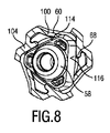
図6〜図13について参照する。図6、図7、及び図8は、雄型コネクタ58及び雌型コネクタ60が互いに角度オフセット態様で係合する第1の継手52の係合状態を示す。また、図9、図10、図12、及び図13は、孤立状態の雌型コネクタ60を示す。図11は、孤立状態の雄型コネクタ58を示す。
Reference is made to FIGS. FIGS. 6, 7, and 8 show the engagement state of the first joint 52 in which the
図6に示されるように、雄型コネクタ58は、雌型コネクタ60と係合して、雌型コネクタ60が取り付けられた伝達シャフト36を駆動することができる。雄型コネクタ58と雌型コネクタ60との間の角度オフセットが存在する場合であっても、同調及び駆動動作を実現することができる。上述したように、雄型コネクタ58には、外部多角形プロファイル62が設けられ、この外部多角形プロファイル62には、凸形状の逃げ面66が少なくとも部分的に設けられる。従って、かなりの角度オフセットが存在する場合であっても、雌型コネクタ60の回転同調が可能になる。
As shown in FIG. 6, the
図7は、雄型コネクタ58が雌型コネクタ60と係合する第1の継手52の側面図を示す。図8は、図7のVIII−VIII線に沿った対応する断面背面図を示す。図9は、基本的に図8の図に対応しており、図9において、雄型コネクタ58は説明のために省略されている。
FIG. 7 shows a side view of the first joint 52 in which the
雌型コネクタ60には、複数の補償要素100が設けられる。補償要素100は、撓み可能な(屈曲)な態様で配置される。好ましくは、補償要素100は、雌型コネクタ60と一体成形される。この目的のために、雌型コネクタ60の基本的に周方向の壁104には、少なくとも部分的に窓又は凹部102が設けられる。窓102において、言わば周方向壁104の一部を形成する補償要素100が配置され得る。図7において確認されるように、補償要素100の片側のみが、周方向壁104の隣接部分に取り付けられる。その結果、補償要素100は、少なくともある程度フレキシブル且つ撓み可能である。一般に、補償要素100は、基本的に長方形の四辺形状で配置してもよい。しかしながら、代替の実施形態が想定され得る。
The
図9に最もよく示されているように、図6〜図13の実施形態によれば、雌型コネクタ60の3つの対応する凹部102内に配置される3つの補償要素100が設けられる。補償要素100は、雌型コネクタ60に対して雄型コネクタ58を好ましい相対的な向きで芯出し(center)するよう半径方向内向き及び外向きに撓み可能である。雄型コネクタ58が雌型コネクタ60に係合すると、補償要素100は、少なくとも僅かに外向きに撓み、付勢力を生成する。付勢されていない状態では、雄型コネクタ58が雌型コネクタ60に係合しないとき、補償要素100は、雄型コネクタ58の外部多角形プロファイル62、特にその軸線方向断面プロファイルよりも僅かに小さい領域を取り囲む。
As best shown in FIG. 9, according to the embodiment of FIGS. 6 to 13, there are provided three compensating
図9において、回転方向46が、それぞれ湾曲した矢印によって示される。補償要素100は、周方向壁104から基本的に周方向に延びることがさらに理解され、その伸長方向は回転方向46に対応する。例示的な実施形態では、補償要素100は、雌型コネクタ60の周方向壁104に、例えば120°(度)のオフセット角で角度的に分布される。
In FIG. 9, the
補償要素100の更なる詳細図が、図10、図12、及び図13に示される。図11は、三角形状に構成された外部多角形プロファイル62を含む雄型コネクタ58の対応する構成を示す。勿論、雄型コネクタ58及び雌型コネクタ60の対応する外部及び内部プロファイルの正方体(tetragonal)形状及び更なる代替形状も想定することができる。さらに、図11から、外部多角形プロファイル62には、角度補償目的のために凸形状の逃げ面66が設けられることが分かる。
Further details of the
補償要素100は、回転同調のための駆動可能な逃げ面70が設けられる係合バー68に対して規定された角度オフセットで配置される(図9も参照)。補償要素100の屈曲運動は、二重矢印118によって図9及び図13に示される。
The compensating
図10及び図12は、雌型コネクタ60、特にその周方向壁104が部分的に中断又は凹状に配置されることを示す。補償要素100は、内向き又は外向きの運動を補償することができるように、基本的に撓み可能且つフレキシブルな態様で配置される。対照的に、係合バー68は、基本的にバックラッシュの無い又はバックラッシが低減された回転伝達を可能にするように基本的に剛性態様で配置される。雌型コネクタ60の周方向壁104の前端は、図10及び図12に参照符号112で示される。こうして、図10、図12、及び図13によれば、周方向壁104は、ケージ状構造を形成し、補償要素100を収容する凹部又は窓102が、閉じたプロファイルによって取り囲まれる。
10 and 12 show that the
図10においてさらに確認されるように、補償要素100は、壁104に設けられたベースに取り付けられたステム部分106を含む。ステム部分106に隣接して、アーム部分108が設けられる。アーム部分108には、雄型コネクタ58の外部多角形プロファイル62に形成された対応する接触面114に接触するように構成された接触面110が配置される(図8も参照)。その結果、付勢力を接触面114に及ぼす際に、雄型コネクタ58の外部多角形プロファイル62にも形成される駆動面116が係合バー68と接触するように付勢される。外部多角形プロファイル62の三角形が凸形状の逃げ面として配置される3つの逃げ面66を含むと仮定すると、各逃げ面66に、接触面114及び駆動面116を設けられ得る。補償要素100の接触面110が外部多角形プロファイル62の対応する接触面114に付勢力を加えるときに、駆動面116と内部係合プロファイル64の駆動可能な逃げ面70との密接な接触が達成される。動作的に結合された接触面114と駆動面116との対は、同じ逃げ面66ではなく、隣接する又は近隣の逃げ面66に配置される。
As further confirmed in FIG. 10, the compensating
こうして、雄型コネクタ58は、(回転)遊び又はクリアランスが殆ど又は全くない状態で、基本的に緊密な態様で雌型コネクタ60に受容される。これにより、雄型コネクタ58と雌型コネクタ60との間の接触状態が改善され、特に、雄型コネクタ58にトルクが加えられていないか、又はほんの極僅かなトルクが加えられるときに、関与する継手の円滑な動作が可能になる。結果として、雄型コネクタ58は、基本的に自己芯出し又は自己整列した態様で雌型コネクタ60に受容され得る。潤滑剤の必要な量を減らすことができる。好ましくは、雄型コネクタ58及び雌型コネクタ60は、無潤滑又は無グリースの動作のために配置される。さらに、摩擦低減コーティングを、少なくとも1つの関与する移動部品に塗布してもよい。
Thus, the
補償要素100の所望の前負荷又は付勢作用は、雄型コネクタ58、特にその外部多角形プロファイル62が少なくとも僅かに前負荷された態様で雌型コネクタ60の内部係合プロファイル64に受容されるように、雌型コネクタ60を適切に成形することによって達成され得る。
The desired preload or biasing action of the compensating
補償要素100の撓み方向118を示す図13をさらに参照する。補償要素100は、基本的に伝達シャフト36の長手方向軸線94に対して平行に配置される(仮想)瞬間的な撓み軸線120が設けられるような方法で、規定された態様で屈曲するように構成される(図4参照)。ある程度、補償要素100は、膨大な数の負荷及び位置の変化に耐えるように、一体型ヒンジ又は一体成形ヒンジとして構成してもよい。
Reference is further made to FIG. 13, which shows the
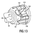
図14及び図15を参照すると、第1の継手52(及び/又は第2の継手54)の代替実施形態が詳細にさらに説明される。この実施形態によれば、雄型コネクタ158(図15)及び雌型コネクタ160(図14)が提供される。図6〜図13の実施形態と同様に、雌型コネクタ160にも、雌型コネクタ160の周方向壁204に沿って角度的に分布した補償要素100が設けられる。
Referring to FIGS. 14 and 15, an alternative embodiment of the first joint 52 (and / or the second joint 54) is further described in detail. According to this embodiment, a male connector 158 (FIG. 15) and a female connector 160 (FIG. 14) are provided. As in the embodiment of FIGS. 6 to 13, the
例えば、3つの補償要素200が設けられ、補償要素は、ステム部分206とそこから延びるアーム部分208とを含む。しかしながら、補償要素200の主伸長方向は、基本的に長手方向軸線94に対して平行である。換言すれば、補償要素200のステム部分206は、雌型コネクタ160の周方向壁204の軸線方向面に取り付けられる。図6〜図13の実施形態と同様に、雄型コネクタ158、特にその外部多角形プロファイル162と接触するように、接触面210がアーム部分208に配置される。
For example, three compensating
補償要素200の撓み方向が、図14に二重矢印218で示される。その結果、長手方向軸線94に対して基本的に垂直に配置される瞬間的な(仮想)撓み軸線220が規定される。図6〜図13の実施形態と同様に、図14の雌型コネクタ60の周方向壁204もまた、部分的に中断され、及び/又は凹部202が設けられ、凹部202には補償要素200が配置される。周方向壁204の前端212が中断される。勿論、前端212は、代替的に、連続的な態様で形成してもよく、図6〜図13の実施形態の前端112を参照する。
The direction of deflection of the compensating
図11の雄型コネクタ58の全体的なレイアウトに基本的に対応する雄型コネクタ158の実施形態を示す図15についてさらに参照する。しかしながら、雄型コネクタ158は、凸形状の逃げ面66に配置された(追加の)凸状突起部をさらに含む。結果的に、既に凸状に形成された逃げ面166において、さらに強い湾曲した突起部228を設けてもよい。凸状突起部228は、雄型コネクタ158の外部多角形プロファイル162において、補償要素200の接触面210による係合が可能になるように配置される。
Reference is further made to FIG. 15, which shows an embodiment of a
また、図14及び図15に示される実施形態では、雄型コネクタ158及び雌型コネクタ160の自己芯出し及び/又は自己整列は、雄型コネクタ158を内部係合プロファイル164に挿入することによって達成され、スナップオン取付け又はクリックオン取付けの適用が含まれ、補償要素200を外向きに撓ませ、それによって所望の芯出し及び/又は整列力を生成する。
Also, in the embodiment shown in FIGS. 14 and 15, self-centering and / or self-alignment of
本発明について図面及び前述の説明において詳細に図示及び説明してきたが、そのような図示及び説明は、例又は例示的であって、限定するものではないとみなすべきであり、本発明は、開示された実施形態に限定されない。開示された実施形態に対する他の変更は、図面、明細書の開示、及び添付の特許請求の範囲の検討から、特許請求の範囲に記載された発明を実施する際に当業者によって理解され、達成され得る。 While the invention has been illustrated and described in detail in the drawings and foregoing description, such illustration and description are to be considered illustrative or illustrative and not restrictive; It is not limited to the embodiment described. Other modifications to the disclosed embodiments will be understood and attained by those skilled in the art in practicing the claimed invention, from a study of the drawings, the disclosure of the specification, and the appended claims. Can be done.
特許請求の範囲において、「備える、有する、含む(comprising)」という単語は他の要素又はステップを排除するものではなく、不定冠詞「1つの(a, an)」は複数を除外するものではない。単一の要素又は他のユニットは、特許請求の範囲に列挙された、いくつかの項目の機能を満たすことができる。特定の手段が互いに異なる従属請求項に列挙されているという単なる事実は、これらの手段の組合せが有利に使用できないことを示すものではない。 In the claims, the word "comprising" does not exclude other elements or steps, and the indefinite article "a (an)" does not exclude a plurality. . A single element or other unit may fulfill the functions of several items recited in the claims. The mere fact that certain measures are recited in mutually different dependent claims does not indicate that a combination of these measures cannot be used to advantage.
特許請求の範囲内のいかなる参照符号も、特許請求の範囲を限定するものとして解釈すべきではない。 Any reference signs in the claims shall not be construed as limiting the claim.
Claims (19)
当該連結リンク機構は、トルク伝達のために互いに係合するように構成された第1のコネクタ部分及び第2のコネクタ部分を含む継手セクションを含み、
前記第1のコネクタ部分は、雄型コネクタの長手方向軸線に対して垂直な断面で視た場合に、外部多角形プロファイルを含む前記雄型コネクタを規定し、前記第2のコネクタ部分は、内部係合プロファイルを含む雌型コネクタを規定し、
前記雄型コネクタ及び前記雌型コネクタは、前記駆動シャフトの前記長手方向軸線と当該連結リンク機構の長手方向軸線との間の角度オフセットを補償するように自己整列態様で構成され、
前記雄型コネクタ及び前記雌型コネクタの少なくとも一方には、前記雄型コネクタ及び前記雌型コネクタを動作整列に向けて付勢するように構成された、周方向に配置された少なくとも1つの撓み可能な補償要素が設けられ、前記周方向は、前記駆動トレインの動作回転方向に対応する、
連結リンク機構。 A self-aligning articulated linkage for a drive train of a hair cutting device, comprising a drive shaft and an output shaft angularly offset with respect to a longitudinal axis of the drive shaft ,
The coupling linkage includes a coupling section including a first connector portion and a second connector portion configured to engage with each other for torque transmission;
The first connector portion defines the male connector including an external polygonal profile when viewed in a cross-section perpendicular to a longitudinal axis of the male connector, and the second connector portion includes an internal connector. Defining a female connector including an engagement profile,
The male connector and the female connector are configured in a self-aligned manner to compensate for an angular offset between the longitudinal axis of the drive shaft and the longitudinal axis of the link mechanism ;
At least one of the male connector and the female connector has at least one circumferentially disposed deflectable configured to bias the male connector and the female connector toward operational alignment. compensation element is provided, et al is Do, the circumferential direction corresponds to the operation direction of rotation of the drive train,
Connecting link mechanism.
当該ヘアカッティング機器は、ハウジングと、該ハウジングに取り付けられたカッティングヘッドと、駆動トレインとを有しており、該駆動トレインは、駆動シャフトと、出力シャフトと、連結リンク機構とを含み、
該連結リンク機構は、トルク伝達のために互いに係合するように構成された第1のコネクタ部分及び第2のコネクタ部分を含む継手セクションを含み、
前記第1のコネクタ部分は、雄型コネクタの長手方向軸線に対して垂直な断面で視た場合に、外部多角形プロファイルを含む前記雄型コネクタを規定し、前記第2のコネクタ部分は、内部係合プロファイルを含む雌型コネクタを規定し、
前記雄型コネクタ及び前記雌型コネクタは、前記駆動シャフトの長手方向軸線と前記連結リンク機構の長手方向軸線との間の角度オフセットを補償するように自己整列態様で構成され、
前記雄型コネクタ及び前記雌型コネクタの少なくとも一方には、前記雄型コネクタ及び前記雌型コネクタを動作整列に向けて付勢するように構成された、周方向に配置された少なくとも1つの撓み可能な補償要素が設けられ、前記周方向は、前記駆動トレインの動作回転方向に対応し、
前記カッティングヘッドはブレードセットを含み、
前記駆動トレインは、前記カッティングヘッドが前記ハウジングに取り付けられたときに、前記ブレードセットを作動させるように構成される、
ヘアカッティング機器。 Hair cutting equipment,
The hair cutting device has a housing, a cutting head attached to the housing, and a drive train, the drive train including a drive shaft, an output shaft, and a link mechanism;
The coupling linkage includes a coupling section including a first connector portion and a second connector portion configured to engage with each other for torque transmission;
The first connector portion defines the male connector including an external polygonal profile when viewed in a cross-section perpendicular to a longitudinal axis of the male connector, and the second connector portion includes an internal connector. Defining a female connector including an engagement profile,
The male connector and the female connector are configured in a self-aligned manner to compensate for an angular offset between a longitudinal axis of the drive shaft and a longitudinal axis of the link mechanism ;
At least one of the male connector and the female connector has at least one circumferentially disposed deflectable configured to bias the male connector and the female connector toward operational alignment. The circumferential direction corresponds to the operating rotation direction of the drive train,
The cutting head includes a blade set;
The drive train is configured to operate the blade set when the cutting head is mounted on the housing.
Hair cutting equipment.
前記主本体部分はモータを収容し、前記ブレードセットは、前記ネック部分に取り付けられており、前記ネック部分は、前記主本体部分の主な向きに対してオフセットした角度で向き合わされており、前記主本体部分は前記駆動シャフトを収容し、前記ネック部分は前記出力シャフトを収容し、前記駆動シャフトの長手方向軸線は、前記出力シャフトの長手方向軸線と総オフセット角(δ)を形成し、前記連結リンク機構の伝達シャフトは、前記駆動シャフトと前記出力シャフトとを連結し、前記伝達シャフトの長手方向軸線は、前記出力シャフトの前記長手方向軸線と第1のオフセット角(β)を形成し、前記伝達シャフトの前記長手方向軸線は、前記駆動シャフトの前記長手方向軸線と第2のオフセット角(α)を形成する、請求項14に記載のヘアカッティング機器。 A main body portion formed by the housing; and a neck portion,
The main body portion houses a motor, the blade set is attached to the neck portion, and the neck portion faces at an angle offset with respect to a main orientation of the main body portion; A main body portion housing the drive shaft, the neck portion housing the output shaft, a longitudinal axis of the drive shaft forming a total offset angle (δ) with a longitudinal axis of the output shaft; A transmission shaft of a coupling link mechanism connects the drive shaft and the output shaft, and a longitudinal axis of the transmission shaft forms a first offset angle (β) with the longitudinal axis of the output shaft; 15. The method of claim 14, wherein the longitudinal axis of the transmission shaft forms a second offset angle (α) with the longitudinal axis of the drive shaft. Placing hair-cutting equipment.
13. The link mechanism of claim 12, wherein the male connector and the female connector are configured in a self-centered manner when engaged with each other.
Applications Claiming Priority (3)
| Application Number | Priority Date | Filing Date | Title |
|---|---|---|---|
| EP15202049 | 2015-12-22 | ||
| EP15202049.1 | 2015-12-22 | ||
| PCT/EP2016/082500 WO2017109143A1 (en) | 2015-12-22 | 2016-12-22 | Coupling mechanism for a drive train of a hair cutting appliance |
Publications (3)
| Publication Number | Publication Date |
|---|---|
| JP2019500123A JP2019500123A (en) | 2019-01-10 |
| JP2019500123A5 JP2019500123A5 (en) | 2019-09-26 |
| JP6666447B2 true JP6666447B2 (en) | 2020-03-13 |
Family
ID=55027429
Family Applications (1)
| Application Number | Title | Priority Date | Filing Date |
|---|---|---|---|
| JP2018532317A Active JP6666447B2 (en) | 2015-12-22 | 2016-12-22 | Coupling mechanism for drive train of hair cutting equipment |
Country Status (5)
| Country | Link |
|---|---|
| US (2) | US10449682B2 (en) |
| EP (1) | EP3240658B1 (en) |
| JP (1) | JP6666447B2 (en) |
| CN (2) | CN207373215U (en) |
| WO (1) | WO2017109143A1 (en) |
Families Citing this family (22)
| Publication number | Priority date | Publication date | Assignee | Title |
|---|---|---|---|---|
| US10406702B2 (en) * | 2014-09-18 | 2019-09-10 | Koninkliike Philips N.V. | Blade set, cutting appliance, and related manufacturing method |
| CN207373215U (en) * | 2015-12-22 | 2018-05-18 | 皇家飞利浦有限公司 | Autoregistration coupling arrangement and hair cutting equipment |
| EP3300846B1 (en) * | 2016-09-28 | 2020-04-15 | Braun GmbH | Electric shaver |
| EP3431792A1 (en) * | 2017-07-18 | 2019-01-23 | Koninklijke Philips N.V. | Coupling unit |
| USD952946S1 (en) | 2017-09-01 | 2022-05-24 | Church & Dwight Co., Inc. | Hair removal device |
| ES2806801T3 (en) | 2017-10-06 | 2021-02-18 | Braun Gmbh | Epilator |
| CN108081324A (en) * | 2017-12-18 | 2018-05-29 | 吴让攀 | Electric hair cutting equipment |
| USD866859S1 (en) * | 2018-01-13 | 2019-11-12 | Shenzhen OuKu E-commerce Co., Ltd. | Hair clipper |
| USD864483S1 (en) * | 2018-01-13 | 2019-10-22 | Shenzhen Ouku E-commerce Co., Ltd | Hair clipper |
| EP3626415A1 (en) * | 2018-09-21 | 2020-03-25 | Koninklijke Philips N.V. | Improved hair-cutting unit for a shaving device |
| CN109822630A (en) * | 2019-01-29 | 2019-05-31 | 温州朗威电器有限公司 | A kind of hair cutting utensil, rotary cutting unit and its rotary connector |
| USD914977S1 (en) | 2019-07-19 | 2021-03-30 | Church & Dwight Co., Inc. | Handle for hair removal apparatus |
| USD925830S1 (en) | 2019-07-19 | 2021-07-20 | Church & Dwight Co., Inc. | Head assembly for hair removal apparatus |
| USD914978S1 (en) | 2019-10-18 | 2021-03-30 | Church & Dwight Co., Inc. | Hair removal apparatus |
| USD936899S1 (en) | 2019-10-18 | 2021-11-23 | Church & Dwight Co., Inc. | Hair removal apparatus |
| JP7457482B2 (en) * | 2019-10-24 | 2024-03-28 | マクセルイズミ株式会社 | rotary electric razor |
| USD940958S1 (en) | 2019-11-18 | 2022-01-11 | Church & Dwight Co., Inc. | Articulating blade assembly for hair removal device |
| USD942687S1 (en) | 2019-11-18 | 2022-02-01 | Church & Dwight Co., Inc. | Articulating blade assembly for hair removal device |
| EP3831555A1 (en) * | 2019-12-04 | 2021-06-09 | Koninklijke Philips N.V. | A shaver head for an electric shaver |
| EP3907044B1 (en) * | 2020-05-08 | 2024-10-16 | Braun GmbH | Electric beard trimmer |
| EP3907048B1 (en) | 2020-05-08 | 2023-03-22 | Braun GmbH | Electric beard trimmer |
| USD1058045S1 (en) * | 2024-04-11 | 2025-01-14 | Yunxia ZHANG | Razor blade head |
Family Cites Families (25)
| Publication number | Priority date | Publication date | Assignee | Title |
|---|---|---|---|---|
| GB148251A (en) | 1917-11-24 | 1921-06-02 | Luftfahrzeugbau Schuette Lanz | Improvements in disengaging couplings |
| CH568753A5 (en) | 1973-08-31 | 1975-11-14 | Oscobal Ag | |
| FR2499645B1 (en) | 1981-02-09 | 1986-05-30 | Glaenzer Spicer Sa | TRIPOD HOMOCINETIC JOINT, ITS ASSEMBLY METHOD AND ITS APPLICATION IN A WHEEL HUB |
| JPS58143786A (en) * | 1982-02-23 | 1983-08-26 | 松下電工株式会社 | Hair cutter |
| JPS60175361A (en) * | 1984-02-20 | 1985-09-09 | Sanyo Electric Co Ltd | Waterproof cell equipment |
| SU1795177A1 (en) * | 1991-05-14 | 1993-02-15 | Kaluzh Mgtu Im N E Baumana | Flexible coupling without clearance |
| JPH06182065A (en) * | 1992-12-18 | 1994-07-05 | Matsushita Electric Works Ltd | Reciprocation type electric razor |
| JPH0968235A (en) * | 1995-08-30 | 1997-03-11 | Isel Kk | Universal joint |
| US5730657A (en) | 1997-03-20 | 1998-03-24 | General Motors Corporation | Shaft coupling |
| JP2002346250A (en) * | 2001-05-22 | 2002-12-03 | Izumi Products Co | Rotary electric razor |
| CN1280071C (en) | 2001-07-30 | 2006-10-18 | 皇家菲利浦电子有限公司 | Coupling for internal cutting member of rotary shaving apparatus |
| CN100415462C (en) * | 2003-01-20 | 2008-09-03 | 皇家飞利浦电子股份有限公司 | Shaving apparatus |
| JP2004329479A (en) * | 2003-05-06 | 2004-11-25 | Izumi Products Co | Rotary electric razor |
| JP4137866B2 (en) * | 2004-10-20 | 2008-08-20 | アスモ株式会社 | motor |
| CN1851282B (en) | 2005-04-21 | 2012-06-27 | Ntn株式会社 | Constant-velocity joint and image forming device |
| JP4903533B2 (en) * | 2006-11-07 | 2012-03-28 | Ntn株式会社 | Assembling method of tripod type constant velocity universal joint |
| US7819752B2 (en) | 2007-05-17 | 2010-10-26 | Hyundai Wia Corporation | Constant velocity joint of tripod type |
| EP2274526B1 (en) * | 2008-04-30 | 2019-01-23 | Dreco Energy Services Ltd. | Drive shaft assembly for a downhole motor |
| EP2123408B1 (en) * | 2008-05-20 | 2012-05-16 | Wella GmbH | Electric hair cutting machine |
| DE102008058890A1 (en) * | 2008-11-26 | 2010-05-27 | Daimler Ag | Homokinetic joint e.g. pot joint, for use in e.g. side shaft of motor vehicle, has bodies arranged between transmission elements and joint outer part, where directions of one body run to directions of other body by preset twisting angle |
| CN201636226U (en) * | 2009-12-18 | 2010-11-17 | 上海采埃孚伦福德底盘技术有限公司 | Axial joint of build-in compensation device |
| JP5156051B2 (en) | 2010-05-06 | 2013-03-06 | 株式会社山下工業研究所 | Universal joint |
| EP2557326A1 (en) | 2011-08-11 | 2013-02-13 | Koninklijke Philips Electronics N.V. | Drive coupling for high-speed rotating brush |
| JP6626455B2 (en) * | 2014-04-18 | 2019-12-25 | コーニンクレッカ フィリップス エヌ ヴェKoninklijke Philips N.V. | Coupling mechanism for drive train of hair cutting device |
| CN207373215U (en) * | 2015-12-22 | 2018-05-18 | 皇家飞利浦有限公司 | Autoregistration coupling arrangement and hair cutting equipment |
-
2016
- 2016-12-22 CN CN201621418256.5U patent/CN207373215U/en not_active Withdrawn - After Issue
- 2016-12-22 JP JP2018532317A patent/JP6666447B2/en active Active
- 2016-12-22 CN CN201611200469.5A patent/CN106903727B/en active Active
- 2016-12-22 WO PCT/EP2016/082500 patent/WO2017109143A1/en active Application Filing
- 2016-12-22 US US15/550,451 patent/US10449682B2/en active Active
- 2016-12-22 EP EP16829080.7A patent/EP3240658B1/en active Active
-
2019
- 2019-09-10 US US16/565,581 patent/US11090823B2/en active Active
Also Published As
| Publication number | Publication date |
|---|---|
| US10449682B2 (en) | 2019-10-22 |
| CN106903727B (en) | 2020-07-31 |
| CN106903727A (en) | 2017-06-30 |
| US20180281213A1 (en) | 2018-10-04 |
| CN207373215U (en) | 2018-05-18 |
| US20200001484A1 (en) | 2020-01-02 |
| JP2019500123A (en) | 2019-01-10 |
| EP3240658B1 (en) | 2018-08-01 |
| EP3240658A1 (en) | 2017-11-08 |
| US11090823B2 (en) | 2021-08-17 |
| WO2017109143A1 (en) | 2017-06-29 |
Similar Documents
| Publication | Publication Date | Title |
|---|---|---|
| JP6666447B2 (en) | Coupling mechanism for drive train of hair cutting equipment | |
| US10279492B2 (en) | Coupling mechanism for a drive train of a hair cutting appliance | |
| US11331820B2 (en) | Motion transmission unit, drive train and hair cutting appliance | |
| JP2019500123A5 (en) | ||
| US10737402B2 (en) | Electric hair cutter | |
| JP2016514557A (en) | Shaving head with pivotable shaving unit | |
| KR102453457B1 (en) | Ball joint with locking ball socket assembly | |
| JP7212668B2 (en) | connecting unit | |
| CN219152954U (en) | Mounting assembly for a hair cutting appliance and hair cutting appliance | |
| US8533962B1 (en) | Clipper lever | |
| EP2509755B1 (en) | Hair clipper device | |
| US8671494B2 (en) | Low friction rotational or translational interface for a mechanical system | |
| US20250017712A1 (en) | Powered toothbrush and brush head assemblies therefor | |
| EP4360830A1 (en) | A mounting assembly | |
| CN120112395A (en) | Mounting assembly |
Legal Events
| Date | Code | Title | Description |
|---|---|---|---|
| A521 | Request for written amendment filed |
Free format text: JAPANESE INTERMEDIATE CODE: A523 Effective date: 20190814 |
|
| A621 | Written request for application examination |
Free format text: JAPANESE INTERMEDIATE CODE: A621 Effective date: 20190814 |
|
| A871 | Explanation of circumstances concerning accelerated examination |
Free format text: JAPANESE INTERMEDIATE CODE: A871 Effective date: 20190814 |
|
| A975 | Report on accelerated examination |
Free format text: JAPANESE INTERMEDIATE CODE: A971005 Effective date: 20190902 |
|
| A131 | Notification of reasons for refusal |
Free format text: JAPANESE INTERMEDIATE CODE: A131 Effective date: 20191015 |
|
| A521 | Request for written amendment filed |
Free format text: JAPANESE INTERMEDIATE CODE: A523 Effective date: 20191210 |
|
| TRDD | Decision of grant or rejection written | ||
| A01 | Written decision to grant a patent or to grant a registration (utility model) |
Free format text: JAPANESE INTERMEDIATE CODE: A01 Effective date: 20200128 |
|
| A61 | First payment of annual fees (during grant procedure) |
Free format text: JAPANESE INTERMEDIATE CODE: A61 Effective date: 20200220 |
|
| R150 | Certificate of patent or registration of utility model |
Ref document number: 6666447 Country of ref document: JP Free format text: JAPANESE INTERMEDIATE CODE: R150 |
|
| R250 | Receipt of annual fees |
Free format text: JAPANESE INTERMEDIATE CODE: R250 |
|
| R250 | Receipt of annual fees |
Free format text: JAPANESE INTERMEDIATE CODE: R250 |
|
| R250 | Receipt of annual fees |
Free format text: JAPANESE INTERMEDIATE CODE: R250 |