JP6663201B2 - Image encoding apparatus and control method thereof, and computer program and storage medium - Google Patents
Image encoding apparatus and control method thereof, and computer program and storage medium Download PDFInfo
- Publication number
- JP6663201B2 JP6663201B2 JP2015211103A JP2015211103A JP6663201B2 JP 6663201 B2 JP6663201 B2 JP 6663201B2 JP 2015211103 A JP2015211103 A JP 2015211103A JP 2015211103 A JP2015211103 A JP 2015211103A JP 6663201 B2 JP6663201 B2 JP 6663201B2
- Authority
- JP
- Japan
- Prior art keywords
- plane
- image data
- raw image
- encoding
- color difference
- Prior art date
- Legal status (The legal status is an assumption and is not a legal conclusion. Google has not performed a legal analysis and makes no representation as to the accuracy of the status listed.)
- Expired - Fee Related
Links
- 238000000034 method Methods 0.000 title claims description 69
- 238000004590 computer program Methods 0.000 title claims description 12
- 238000006243 chemical reaction Methods 0.000 claims description 116
- 238000013139 quantization Methods 0.000 claims description 37
- 238000003384 imaging method Methods 0.000 claims description 35
- 238000004364 calculation method Methods 0.000 claims description 32
- 230000008569 process Effects 0.000 claims description 30
- 230000006835 compression Effects 0.000 claims description 17
- 238000007906 compression Methods 0.000 claims description 17
- 238000011156 evaluation Methods 0.000 claims description 8
- 238000012545 processing Methods 0.000 description 76
- 238000010586 diagram Methods 0.000 description 25
- 239000000872 buffer Substances 0.000 description 20
- 238000000605 extraction Methods 0.000 description 13
- 230000006870 function Effects 0.000 description 9
- 230000004048 modification Effects 0.000 description 9
- 238000012986 modification Methods 0.000 description 9
- 230000006866 deterioration Effects 0.000 description 6
- 230000010365 information processing Effects 0.000 description 6
- 230000008901 benefit Effects 0.000 description 3
- 230000008859 change Effects 0.000 description 3
- 230000000694 effects Effects 0.000 description 3
- 238000005070 sampling Methods 0.000 description 3
- 230000000007 visual effect Effects 0.000 description 3
- 230000003287 optical effect Effects 0.000 description 2
- 238000007781 pre-processing Methods 0.000 description 2
- 238000002360 preparation method Methods 0.000 description 2
- 230000004913 activation Effects 0.000 description 1
- 230000015556 catabolic process Effects 0.000 description 1
- 239000000470 constituent Substances 0.000 description 1
- 238000006731 degradation reaction Methods 0.000 description 1
- 238000011161 development Methods 0.000 description 1
- 239000004973 liquid crystal related substance Substances 0.000 description 1
- 238000004091 panning Methods 0.000 description 1
- 230000000737 periodic effect Effects 0.000 description 1
- 230000009467 reduction Effects 0.000 description 1
- 230000035945 sensitivity Effects 0.000 description 1
Images


Classifications
-
- H—ELECTRICITY
- H04—ELECTRIC COMMUNICATION TECHNIQUE
- H04N—PICTORIAL COMMUNICATION, e.g. TELEVISION
- H04N19/00—Methods or arrangements for coding, decoding, compressing or decompressing digital video signals
- H04N19/10—Methods or arrangements for coding, decoding, compressing or decompressing digital video signals using adaptive coding
- H04N19/169—Methods or arrangements for coding, decoding, compressing or decompressing digital video signals using adaptive coding characterised by the coding unit, i.e. the structural portion or semantic portion of the video signal being the object or the subject of the adaptive coding
- H04N19/186—Methods or arrangements for coding, decoding, compressing or decompressing digital video signals using adaptive coding characterised by the coding unit, i.e. the structural portion or semantic portion of the video signal being the object or the subject of the adaptive coding the unit being a colour or a chrominance component
-
- G—PHYSICS
- G06—COMPUTING; CALCULATING OR COUNTING
- G06T—IMAGE DATA PROCESSING OR GENERATION, IN GENERAL
- G06T3/00—Geometric image transformation in the plane of the image
- G06T3/40—Scaling the whole image or part thereof
- G06T3/4015—Demosaicing, e.g. colour filter array [CFA], Bayer pattern
-
- G06T5/70—
-
- H—ELECTRICITY
- H04—ELECTRIC COMMUNICATION TECHNIQUE
- H04N—PICTORIAL COMMUNICATION, e.g. TELEVISION
- H04N19/00—Methods or arrangements for coding, decoding, compressing or decompressing digital video signals
- H04N19/10—Methods or arrangements for coding, decoding, compressing or decompressing digital video signals using adaptive coding
- H04N19/102—Methods or arrangements for coding, decoding, compressing or decompressing digital video signals using adaptive coding characterised by the element, parameter or selection affected or controlled by the adaptive coding
- H04N19/103—Selection of coding mode or of prediction mode
-
- H—ELECTRICITY
- H04—ELECTRIC COMMUNICATION TECHNIQUE
- H04N—PICTORIAL COMMUNICATION, e.g. TELEVISION
- H04N19/00—Methods or arrangements for coding, decoding, compressing or decompressing digital video signals
- H04N19/10—Methods or arrangements for coding, decoding, compressing or decompressing digital video signals using adaptive coding
- H04N19/102—Methods or arrangements for coding, decoding, compressing or decompressing digital video signals using adaptive coding characterised by the element, parameter or selection affected or controlled by the adaptive coding
- H04N19/124—Quantisation
-
- H—ELECTRICITY
- H04—ELECTRIC COMMUNICATION TECHNIQUE
- H04N—PICTORIAL COMMUNICATION, e.g. TELEVISION
- H04N19/00—Methods or arrangements for coding, decoding, compressing or decompressing digital video signals
- H04N19/10—Methods or arrangements for coding, decoding, compressing or decompressing digital video signals using adaptive coding
- H04N19/134—Methods or arrangements for coding, decoding, compressing or decompressing digital video signals using adaptive coding characterised by the element, parameter or criterion affecting or controlling the adaptive coding
- H04N19/146—Data rate or code amount at the encoder output
- H04N19/15—Data rate or code amount at the encoder output by monitoring actual compressed data size at the memory before deciding storage at the transmission buffer
-
- H—ELECTRICITY
- H04—ELECTRIC COMMUNICATION TECHNIQUE
- H04N—PICTORIAL COMMUNICATION, e.g. TELEVISION
- H04N19/00—Methods or arrangements for coding, decoding, compressing or decompressing digital video signals
- H04N19/60—Methods or arrangements for coding, decoding, compressing or decompressing digital video signals using transform coding
- H04N19/63—Methods or arrangements for coding, decoding, compressing or decompressing digital video signals using transform coding using sub-band based transform, e.g. wavelets
- H04N19/635—Methods or arrangements for coding, decoding, compressing or decompressing digital video signals using transform coding using sub-band based transform, e.g. wavelets characterised by filter definition or implementation details
-
- H—ELECTRICITY
- H04—ELECTRIC COMMUNICATION TECHNIQUE
- H04N—PICTORIAL COMMUNICATION, e.g. TELEVISION
- H04N2209/00—Details of colour television systems
- H04N2209/04—Picture signal generators
- H04N2209/041—Picture signal generators using solid-state devices
- H04N2209/042—Picture signal generators using solid-state devices having a single pick-up sensor
- H04N2209/045—Picture signal generators using solid-state devices having a single pick-up sensor using mosaic colour filter
- H04N2209/046—Colour interpolation to calculate the missing colour values
-
- H—ELECTRICITY
- H04—ELECTRIC COMMUNICATION TECHNIQUE
- H04N—PICTORIAL COMMUNICATION, e.g. TELEVISION
- H04N25/00—Circuitry of solid-state image sensors [SSIS]; Control thereof
- H04N25/70—SSIS architectures; Circuits associated therewith
- H04N25/71—Charge-coupled device [CCD] sensors; Charge-transfer registers specially adapted for CCD sensors
- H04N25/75—Circuitry for providing, modifying or processing image signals from the pixel array
Description
本発明は、ベイヤ配列のRAW画像データの符号化技術に関するものである。 The present invention relates to a technique for encoding RAW image data having a Bayer array.
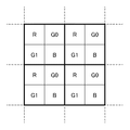
昨今、デジタルカメラ等の撮像装置では、撮像素子にCCDセンサまたはCMOSセンサを採用している。それらのセンサは、センサ表面のカラーフィルターアレイ(以下、CFAと呼ぶ)によって1つの画素で1つの色成分を構成している。CFAを用いることで、図2に示すようなR(赤)、G0(緑)、B(青)、G1(緑)の2×2画素の周期的なパターンで配置されたベイヤ配列の画像データ(以下、RAW画像データと呼ぶ)が得られる。人間の視覚特性は、輝度成分に対して特に高い感度を持っている。このことから、一般的なベイヤ配列においては、図2に示すように輝度成分を多く含む緑成分の画素数は、赤成分や青成分の画素数の2倍となっている。RAW画像データは、1画素に1つの色成分の情報しか持たない。これに対し、人間が視覚することになる通常のカラー画像における1画素は、赤、青、緑の3成分で構成される。それ故、RAW画像データについてデモザイクと呼ばれる処理を適用することで、1画素が赤、青、緑の3つの成分を持つRGB画像データに変換される。一般に、データ量を圧縮するため、デモザイクによって得られたRGB画像データ、あるいは、RGB画像データから変換して得られたYUV画像データに対して符号化処理が適用される。しかしながら、デモザイク処理によって1画素に3つの色成分を持つので、デモザイク処理後の画像データのデータ量は、RAW画像データのそれの3倍となる。それ故、デモザイク前のRAW画像データを直接、符号化して記録する方法が提案されている。 Recently, imaging devices such as digital cameras employ a CCD sensor or a CMOS sensor as an imaging device. In these sensors, one pixel constitutes one color component by a color filter array (hereinafter referred to as CFA) on the sensor surface. By using CFA, Bayer array image data arranged in a periodic pattern of 2 × 2 pixels of R (red), G0 (green), B (blue), and G1 (green) as shown in FIG. (Hereinafter referred to as RAW image data). Human visual characteristics have particularly high sensitivity to luminance components. For this reason, in a general Bayer array, as shown in FIG. 2, the number of pixels of the green component including many luminance components is twice the number of pixels of the red component and the blue component. The RAW image data has only one color component information per pixel. On the other hand, one pixel in a normal color image that can be seen by a human is composed of three components of red, blue, and green. Therefore, by applying a process called demosaicing to the RAW image data, one pixel is converted to RGB image data having three components of red, blue, and green. Generally, in order to compress the data amount, an encoding process is applied to RGB image data obtained by demosaicing, or YUV image data obtained by converting RGB image data. However, since one pixel has three color components by demosaic processing, the data amount of image data after demosaic processing is three times that of RAW image data. Therefore, a method of directly encoding and recording RAW image data before demosaicing has been proposed.
特許文献1には、ベイヤ配列のR成分で構成される画像データ、G0成分で構成される画像データ、B成分で構成される画像データ、そして、G1成分で構成される画像データの4つのプレーンに分離し、各プレーンを符号化する方法が示されている。
また、特許文献2には、RAW画像データを特許文献1と同様にR、G0、B、G1の4つのプレーンに分離した後、近似的に輝度Yと、色差Co、Cg、Dgに変換し符号化する方法が示されている。
Japanese Patent Application Laid-Open No. H11-163873 discloses that RAW image data is separated into four planes of R, G0, B, and G1 in the same manner as in
特許文献1の手法の場合、空間的な距離が近く、かつ同色のため相関が高いG0成分とG1成分とを別々のプレーンとして符号化する。それ故、この手法では、G0,G1成分の両方を含む1プレーンとして符号化する場合と比較し、その符号化効率は劣る。
In the case of the method of
一方、特許文献2の手法は、人間の視覚特性を利用して、輝度(Y)プレーンに多くの符号量を割り振るので解像感の低下を防ぐことができ、且つ、符号化効率は特許文献1の手法と比較すると高い。しかし、特許文献2の手法で符号化した場合、例えばユーザが復号処理を経て、現像およびカラーグレーディングを行う場合、その処理の設定によっては想定外の色ノイズが発生してしまう可能性がある。
On the other hand, the method disclosed in
本発明は、符号化効率と画質のいずれを優先するかに応じた、ベイヤ配列のRAW画像データの符号化技術を提供しようとするものである。また、他の発明は、RAW画像データの符号化効率を優先しながらも、RAW画像データに応じて画質劣化を抑制した符号化を行う技術を提供しようとするものである。 An object of the present invention is to provide a technique for encoding RAW image data in a Bayer array according to whether encoding efficiency or image quality is prioritized. Another object of the present invention is to provide a technique for performing encoding in which image quality deterioration is suppressed in accordance with RAW image data while giving priority to encoding efficiency of RAW image data.
この課題を解決するため、例えば本発明の実施態様に従えば、符号化装置は以下の構成を備える。すなわち、
ベイヤ配列のRAW画像データを符号化する符号化装置であって、
複数のRAW画像データを時系列に入力する入力手段と、
前記RAW画像データを、R成分で構成されるRプレーン、G0成分で構成されるG0プレーン、G1成分で構成されるG1プレーン、及び、B成分で構成されるBプレーンの計4プレーンで構成される第1プレーン群に変換する第1の変換手段と、
RAW画像データを、輝度成分で構成される輝度プレーンとそれぞれが互いに異なる色差成分で構成される3つの色差プレーンとの計4プレーンで構成される第2プレーン群に変換する第2の変換手段と、
前記第1プレーン群または前記第2プレーン群を符号化する符号化手段と、
符号化対象のRAW画像データを、前記第1プレーン群または前記第2プレーン群のいずれに変換するかを決定し、前記決定されたプレーン群の各プレーンを前記符号化手段により符号化するように制御する制御手段とを有し、
前記制御手段は、
前記入力手段に入力される最初のRAW画像データについては、前記第2の変換手段で前記第2プレーン群に変換して符号化するように制御し、
前記入力手段に入力される2番目以降のRAW画像データについては、前記最初のRAW画像データに基づいて、前記第1プレーン群または前記第2プレーン群のいずれに変換するかを決定することを特徴とする。
In order to solve this problem, for example, according to an embodiment of the present invention, an encoding device has the following configuration. That is,
An encoding device for encoding RAW image data having a Bayer array,
Input means for inputting a plurality of RAW image data in time series;
The RAW image data is composed of a total of four planes: an R plane composed of R components, a G0 plane composed of G0 components, a G1 plane composed of G1 components, and a B plane composed of B components. First conversion means for converting into a first plane group,
A second conversion unit configured to convert the RAW image data into a second plane group including a total of four planes including a luminance plane including a luminance component and three color difference planes including respective color difference components; ,
Encoding means for encoding the first plane group or the second plane group;
It is determined whether the RAW image data to be encoded is to be converted into the first plane group or the second plane group, and each plane of the determined plane group is encoded by the encoding means. possess and control means for controlling,
The control means includes:
The first RAW image data input to the input unit is controlled by the second conversion unit so as to be converted into the second plane group and encoded.
For the second and subsequent RAW image data input to the input means, it is determined which of the first plane group and the second plane group is to be converted based on the first RAW image data. And
また、他の実施態様に従えば、符号装置は以下の構成を備える。すなわち、
ベイヤ配列のRAW画像データを符号化する符号化装置であって、
RAW画像データを、輝度成分で構成される輝度プレーンとそれぞれが互いに異なる色差成分で構成される3つの色差プレーンとの計4プレーンに変換する変換手段と、
RAW画像データの目標符号量を設定する設定手段と、
前記3つの色差プレーンのうちの少なくとも1つの色差プレーンを解析することで、前記設定手段で設定したRAW画像データの目標符号量から前記輝度プレーンに割り当てる量を決定し、且つ、前記目標符号量における、前記輝度プレーンに割り振った量を減じた残りの量を、各色差プレーンに分配して割り当てる割り当て手段と、
前記変換手段で変換して得られた輝度プレーン、及び3つの色差プレーンのそれぞれを、前記割り当て手段で割り当てた各プレーンに割り当てた符号量を目標符号量として符号化する符号化手段とを有する。
According to another embodiment, an encoding device has the following configuration. That is,
An encoding device for encoding RAW image data having a Bayer array,
Conversion means for converting the RAW image data into a total of four planes including a luminance plane composed of luminance components and three color difference planes each composed of mutually different color difference components;
Setting means for setting a target code amount of the RAW image data;
By analyzing at least one of the three color difference planes, an amount to be assigned to the luminance plane is determined from a target code amount of the RAW image data set by the setting means, and Allocating means for distributing and allocating the remaining amount obtained by subtracting the amount allocated to the luminance plane to each chrominance plane,
Encoding means for encoding each of the luminance plane and the three chrominance planes obtained by conversion by the conversion means, with a code amount allocated to each plane allocated by the allocation means as a target code amount.
本発明によれば、符号化効率と画質のいずれを優先するかに応じた、ベイヤ配列のRAW画像データの符号化技術を提供することが可能となる。また、他の発明によれば、RAW画像データの符号化効率を優先しながらも、RAW画像データに応じて画質劣化を抑制した符号化を行う技術を提供することが可能になる。 ADVANTAGE OF THE INVENTION According to this invention, it becomes possible to provide the encoding technique of the RAW image data of a Bayer arrangement according to which of encoding efficiency or image quality is prioritized. According to another aspect of the present invention, it is possible to provide a technique for performing encoding in which image quality deterioration is suppressed in accordance with RAW image data, while giving priority to encoding efficiency of RAW image data.
以下、添付図面に従って本発明に係る実施形態を詳細に説明する。なお、本発明は、ベイヤ配列のRAW画像データの符号化に関わるものであり、そのRAW画像データの供給源の種類は問わない。例えば記憶媒体がRAW画像データの供給源であっても構わない。ただし、理解を容易にするため、以下の各実施形態では、ベイヤ配列の撮像素子を含む撮像装置におけるRAW画像データの符号化を説明する。 Hereinafter, embodiments of the present invention will be described in detail with reference to the accompanying drawings. Note that the present invention relates to encoding of RAW image data in a Bayer array, and there is no limitation on the type of a source of the RAW image data. For example, the storage medium may be a source of RAW image data. However, in order to facilitate understanding, in each of the following embodiments, encoding of RAW image data in an imaging apparatus including a Bayer array imaging element will be described.
[第1の実施形態]
図15は実施形態が適用する撮像装置のブロック構成図である。CPU1501はプログラムを実行することでバス1512に接続された以下に説明する各構成要素を制御する。ROM1502は、装置の設定に必要な各種データ、並びに、CPU1501が実行するプログラムを格納している。RAM1503は、CPU1501のワークエリアや各種バッファとして機能する。操作部1504は、電源のON/OFFのスイッチ、撮像記録を指示するスイッチ、モード切換のスイッチ、更にはタッチパネルを含む。表示部1505は液晶等、フラットタイプのもので、各種メニューや撮像画像を表示する。操作部1504のタッチパネルは、この表示部1505の表示画面の前面に設けられる。よって、ユーザは表示画面に表示された各種メニュー項目を指でタッチすることで、該当する項目を選択できる。そして、これら操作部1504及び表示部1505が、ユーザインターフェースとして機能することになる。撮像部1506は、フォーカスレンズ、ズームレンズ等の光学レンズ1506a、結像した像を電気信号に変換する撮像素子1506bを含む。この撮像素子1506bは、ベイヤタイプのカラーフィルターアレイを有する。撮像素子1506bから得られた電気信号はA/D変換器1507にてデジタル画像データに変換される。A/D変換器1507からのデジタル画像データは、ベイヤ配列のデータであり、且つ、各種画像処理を施す前のデータである。よって、以降、A/D変換器1507で得られた直後の、ベイヤ配列のデジタル画像データをRAWデータと呼ぶ。撮像制御部1508はCPU1501の制御下にて撮像部1506の光学レンズ1506aのズームレンズやフォーカスレンズの位置調整を行う。画像処理部1509はホワイトバランス処理、RAWデータから表示部1505に表示するための1画素当たりRGBの3成分への変換処理、更には、撮像したRAWデータの圧縮符号化処理とその復号処理を行う。メモリカードインターフェース1510は、CPU1501の制御下で、脱着可能なメモリカード(たとえばSDカード)1511への書き込み及び読出しを行う。
[First Embodiment]
FIG. 15 is a block diagram of an imaging apparatus to which the embodiment is applied. The
以上実施形態における撮像装置の基本構成を説明した。撮像時の撮像制御部1507によるフォーカシング処理、画像処理部1509におけるホワイトバランス処理や、表示のためのRAWデータ→RGBデータへの変換処理等は、本発明の主眼ではないので説明は省略する。以下、操作部1504によって動画像の撮像記録が開始指示された場合の、画像処理部1509におけるRAWデータの符号化について説明する。
The basic configuration of the imaging apparatus according to the embodiment has been described above. The focusing processing by the
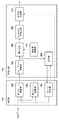
図1は、画像処理部1509に含まれるRAWデータ符号化部のブロック構成図である。このRAWデータ符号化部は、RAWデータの変換法を判定する判定部111と、判定部111の判定結果に応じて符号化処理を実行する符号化部112とを有する。
FIG. 1 is a block diagram of the RAW data encoding unit included in the
判定部111は、フレームメモリ101、第1プレーン変換部102、第2プレーン変換部103、プレーン判定部104、色差変換部108、特徴抽出部109を有する。実施形態における判定部111が入力することになるRAWデータは、既に説明したようにベイヤ配列の画像データである。
The
符号化部105は、ウェーブレット変換部105、量子化部106、エントロピー符号化部107、符号量制御部110、符号列生成部113を含む。また、実施形態における符号化部105は、JPEG2000に準拠して符号化するものとするが、その符号化方式についても問わない。
The
以上、実施形態におけるRAWデータ符号化部の構成について説明した。次に、RAWデータの符号化処理を、上記の各構成要素を用いて更に詳しく説明する。 The configuration of the RAW data encoding unit according to the embodiment has been described. Next, the encoding process of the RAW data will be described in more detail using the above-described components.
フレームメモリ101には、A/D変換器1507より得られたRAWデータが撮像タイミングに従って順に格納されていく。そして、プレーン判定部104は、後述する特徴抽出部109による処理結果に基づき、フレームメモリ101に格納されたRAWデータを、後述する第1プレーン群、第2プレーン群のいずれに変換すべきかを判定する。そして、プレーン判定部104は、その判定結果に従い、フレームメモリ101内のRAWデータを、所定の符号化処理のタイミングで読み出し、第1プレーン変換部102、第2プレーン変換部103のいずれか一方に供給する。なお、プレーン判定部104における判定処理の詳細については後述する。このようにフレームメモリ101は、プレーン判定部104による読出しタイミングとなるまで、RAWデータを記憶保持するバッファとして機能することになる。
The RAW data obtained from the A /
図3を参照して第1プレーン変換部102、第2プレーン変換部103を説明する。
The first
第1プレーン変換部102は、ベイヤ配列のRAWデータを、R成分のみで構成されるRプレーン、G0成分のみで構成されるG0プレーン、G1成分のみで構成されるG1プレーン、そして、B成分のみで構成されるBプレーンの計4プレーンに変換する。そして、第1プレーン変換部102は、Rプレーン、G0プレーン、G1プレーン、Bプレーンを、この順に符号化部112に供給する。先に説明した第1プレーン群は、ここで示したR、G0、G1、Bプレーンの総称である。
The first
第2プレーン変換部103は内部にバッファメモリを有し、RAWデータ中のベイヤ配列の2×2画素であるR,G0,G1,Bの各値を、以下の式(1)に従い、近似的に1つの輝度Yと、3つの色差Co,Cg,Dgに変換し、バッファメモリに格納する。そして、第2プレーン変換部103は、この変換処理をRAWデータの全画素に対して行う。この結果、第2プレーン変換部103のバッファメモリには、輝度Yのみで構成されるYプレーン、色差Coのみで構成されるCoプレーン、色差Cgのみで構成されるCgプレーン、色差Dgのみで構成されるDgプレーンの計4プレーンが生成される。そして、第2プレーン変換部103は、生成したYプレーン、Coプレーン、Cgプレーン、Dgプレーンを、この順に符号化部112に供給する。先に説明した第2プレーン群は、ここで示したY,Co,Cg,Dgのプレーンの総称である。

上記のように判定部111は、R、G0、G1、B、Y、Co、Cg、Dgのいずれかのプレーンを1つずつ符号化部112に供給する。ただし、判定部111から符号化部111に連続して供給される4つのプレーンは、{R,G0,G1,B}、又は、{Y,Co,Cg,Dg}のいずれか一方である。そして、符号化部112は、入力したプレーンを、所謂モノクロ多値画像データであるものとして符号化することになる。説明を単純なものとするため、いずれのプレーンであるかを問わず、そのプレーンに含まれる個々のデータを便宜的に画素と呼ぶこととする。以下、実施形態における符号化部112の処理を説明する。
As described above, the
ウェーブレット変換部105は、RAW画像入力部111から1つのプレーン(以下、着目プレーン)に対してウェーブレット変換処理を実行し、複数のサブバンドを生成する。そして、ウェーブレット変換部105は、生成された複数のサブバンドを量子化部106に供給する。
The
ここで、ウェーブレット変換部105のブロック構成図を図4に示す。同図は、JPEG2000でも採用されている構成と同じであり、且つ、ウェーブレット変換を1回行うための構成を示している。図示の符号400が、判定部111から入力した1プレーンであり、便宜的に「入力画像」と表現している。入力画像400は、垂直LPF(垂直ローパスフィルタ)401と垂直HPF(垂直ハイパスフィルタ)402に供給される。垂直LPF401は、入力画像400中の垂直方向に並ぶ画素の低周波成分を通過させる。垂直ハイパスフィルタ402は入力画像中の垂直方向に並ぶ画素の高周波成分を通過させる。そして、垂直LPF401及び垂直HPF402を通して抽出されたデータそれぞれは、ダウンサンプリング回路403、404によって、垂直方向に2:1にダウンサンプリングされる。この結果、入力画像400の垂直方向の解像度に対して1/2の解像度を持つ低周波成分のデータと高周波成分のデータが得られる。
Here, a block diagram of the
ダウンサンプリング回路403より得られた垂直方向の低周波成分のデータは、水平LPF405、水平HPF406に供給される。水平LPF405は、入力したデータから、水平方向に並ぶ低周波成分を通過させる。水平HPF406は、入力したデータから、水平方向に並ぶ高周波成分を通過させる。水平LPF405及び水平HPF406で得られたデータは、ダウンサンプリング回路409、410を介して水平方向に2:1にダウンサンプリングされる。この結果、ダウンサンプリング回路409からは、入力画像400に対し、水平及び垂直方向とも1/2の解像度のサブバンドLLを示す変換係数データが得られる。また、ダウンサンプリング回路410からは、入力画像400に対し、水平及び垂直方向とも1/2の解像度のサブバンドLHを示す変換係数データが得られる。
The data of the low frequency component in the vertical direction obtained from the
ダウンサンプリング回路404より得られた垂直方向の高周波成分のデータは、水平LPF407、水平HPF408に供給される。水平LPF407は、入力したデータから、水平方向に並ぶ低周波成分を通過させる。水平HPF408は、入力したデータから、水平方向に並ぶ高周波成分を通過させる。水平LPF407及び水平HPF408で得られたデータは、ダウンサンプリング回路411、412を介して水平方向に2:1にダウンサンプリングされる。この結果、ダウンサンプリング回路411からは、入力画像400に対し、水平及び垂直方向とも1/2の解像度のサブバンドHLを示す変換係数データが得られる。また、ダウンサンプリング回路412からは、入力画像400に対し、水平及び垂直方向とも1/2の解像度のサブバンドHHを示す変換係数データが得られる。
The data of the high frequency component in the vertical direction obtained from the
図示の符号413は、ダウンサンプリング回路409乃至412から出力された変換係数データで構成されるサブバンドLL、HL、LH,HHを示している。ここで、サブバンドLLは、入力画像400の水平、垂直とも低周波の変換係数データで構成されるものであり、入力画像400の縮小画像と見ることができる。また、サブバンドHH、HL、LHに含まれる変換係数データは、その多くが十分に小さい値であり、高い符号化効率が期待できる。上記は、ウェーブレット変換を1回行う場合の説明である。2回以上のウェーブレット変換は、直前の変換で得られたサブバンドLLを再帰的に入力画像400として用いることで実現できる。
符号量制御部110は、ユーザが操作部1504から設定した圧縮率に従い、各フレームおよび各プレーンに割り振る目標符号量を決定し、その決定した目標符号量を量子化部106に設定する。なお、ここで言うフレームとは、1枚のRAWデータの画像を意味する。
The code
量子化部106は、ウェーブレット変換部105から送られた変換係数データを、符号量制御部110から設定された目標符号量を基づいて決定した量子化パラメータを用いて量子化する。そして量子化部106は、量子化後の変換係数データをエントロピー符号化部107に供給する。なお、設定される目標符号量が少ないほど大きな量子化ステップを選択することになる。
The
エントロピー符号化部107は、量子化部106で量子化後の変換係数データを、サブバンドごとに、EBCOT(Embedded Block Coding with Optimized Truncation)などのエントロピー符号化を施し、符号化データを生成する。
The
符号列生成部113は内部にバッファメモリを有する。また、符号列生成部113は、プレーン判定部104から制御信号を受信する。この制御信号は、フレームメモリ101からのRAWデータの供給先として、第1プレーン変換部102、第2プレーン変換部103のいずれに供給したかを表す信号である。つまり、この制御信号は、エントロピー符号化部107が生成中の符号化データが、第1プレーン群{R,G0,G1,B}に属するプレーンの符号化データであるか、第2プレーン群{Y,Co,Cg,Dg}に属するプレーンの符号化データであるかを示す。符号列生成部113は、内部のバッファメモリに4プレーン分の符号化データが蓄積されたとき、プレーン判定部104からの制御信号に従った識別情報を含むヘッダを生成し、RAM1503に予め確保された書き込みバッファに出力する。そしてプレーン判定部104は、そのヘッダに後続して4プレーン分の符号化データを所定の順番に、その書き込みバッファに出力する。ここで、識別情報は、ヘッダに後続する符号化データが第1プレーン群{R,Go,G1,B}、第2プレーン群{Y,Co,Cg,Dg}のいずれであるかを示す情報である。
The
なお、書き込みバッファにある程度の符号化データが格納されるたびに、CPU1501は、メモリカードI/F1510を制御し、書き込みバッファに蓄積されたデータのメモリカード1511への記録を行わせる。ただし、メモリカード1511への記録処理は、本発明の主眼ではないので、ここでの詳述は省略する。
Each time a certain amount of encoded data is stored in the write buffer, the
次に、判定部111における、色差変換部108、特徴抽出部109、及び、プレーン判定部104の処理を説明する。プレーン判定部104は、色差変換部108、特徴抽出部109を経て得たデータに基づき、RAWデータの供給先として、第1プレーン変換部102、第2プレーン変換部103のいずれにするかを決定する。なお、プレーン判定部104は、この判定を行った際の信号を、先に説明した制御信号として符号列生成部113に出力する。
Next, processing of the color
RAWデータを非可逆符号化する場合において、第1プレーン群{R,G0,G1,B}の符号化と、第2プレーン群{Y,Co,Cg,Dg}の符号化とを比較したとき、後者の方が高い圧縮率が期待できる。しかし、後者の符号化が採用された場合、その復号画像に対して、強いカラーグレーディング等の処理を行うと、ユーザの意図しない色ノイズが発生する可能性がある。これに対し、前者の符号化を採用した場合、カラーグレーディング処理を行っても色ノイズの発生は無い、もしくは無視できる程度である。 When comparing the encoding of the first plane group {R, G0, G1, B} with the encoding of the second plane group {Y, Co, Cg, Dg} when irreversibly encoding RAW data In the latter case, a higher compression ratio can be expected. However, when the latter encoding is employed, if processing such as strong color grading is performed on the decoded image, color noise that the user does not intend may occur. On the other hand, when the former coding is adopted, no color noise is generated or negligible even if the color grading process is performed.
そこで、本実施形態では、ユーザがカラーグレーディング等の画像処理を行えるツールを有していることを想定する。そして、そのツールを活用した場合に色ノイズが発生しやすい性質を持つRAWデータについては、RAWデータを第1プレーン群に変換して符号化を行う。一方、色ノイズが発生し難い性質を持つRAWデータについは、第2プレーン群に変換して符号化を行うことで、符号化効率を高める。そのため、RAWデータ(以下、着目RAWデータという)が上記性質を含んでいるか否かを判定もしくは推定する必要がある。以下、この判定に係る処理を説明する。 Therefore, in the present embodiment, it is assumed that the user has a tool that can perform image processing such as color grading. Then, with regard to RAW data having a property that color noise easily occurs when the tool is utilized, the RAW data is converted into a first plane group and encoded. On the other hand, RAW data having a property that color noise is unlikely to be generated is converted into a second plane group and encoded, thereby improving encoding efficiency. Therefore, it is necessary to determine or estimate whether or not the RAW data (hereinafter, referred to as RAW data of interest) includes the above property. Hereinafter, the processing related to this determination will be described.
色差変換部108は、フレームメモリ101に格納することになる着目RAWデータから、先に示した式(1)に従い、色差成分Co,Cg,Dgを算出する。色差変換部108は、算出した色差成分Co,Cg,Dgを内部に設けられた不図示のバッファメモリに蓄積する。着目RAWデータの全画素についての色差成分の算出を終えたとき、内部バッファにはCo,Cg,Dgの各プレーンが格納されることになる。なお、Co,Cg,Dgに含まれる各データは式(1)に示すように色差データであるが、ここでも便宜的に画素、その値を画素値と表現する。
The color
特徴抽出部109は、次式(2)に従い、色差変換部108が生成したCoプレーン、Cgプレーン、Dgプレーンの画素値の分散値VarCo,VarCg,VarDgを算出する。そして、特徴抽出部109は、算出した分散値VarCo,VarCg,VarDgを、着目RAWデータの特徴データとしてプレーン判定部104に供給する。
プレーン判定部104は、特徴抽出部109から供給されたVarCo,VarCg,VarDgに基づいて、着目RAWデータを第1プレーン群、第2プレーン群のいずれに変換すべきかを判定する。そして、プレーン判定部104は、着目RAWデータは第1プレーン群に変換すべきと判定した場合、その着目RAWデータを第1プレーン変換部102に供給する。また、プレーン判定部104は、着目RAWデータは第2プレーン群に変換すべきと判定した場合、その着目RAWデータを第2プレーン変換部102に供給する。
Based on VarCo, VarCg, and VarDg supplied from the
ここで分散VarCoに対応する閾値をThCo、分散VarCgに対応する閾値をThCg、分散VarDgに対応する閾値をThDgと定義する。プレーン判定部104は、以下の条件を満たすか否かの条件判定を行う。この条件を満たす場合、プレーン判定部104は、着目RAWデータが第2プレーン群への変換には適さないと判定し、着目RAWデータを第1プレーン群{R,G0,G1,B}に変換するとして決定する。
VarCo>ThCo、又は、
VarCg>ThCg、又は、
VarDg>ThDg
一方、上記条件を満たさない場合、プレーン判定部104は着目RAWデータを第2プレーン群{Y,Co,Cg,Dg}に変換すると決定する。
Here, the threshold value corresponding to the variance VarCo is defined as ThCo, the threshold value corresponding to the variance VarCg is defined as ThCg, and the threshold value corresponding to the variance VarDg is defined as ThDg. The
VarCo> ThCo, or
VarCg> ThCg, or
VarDg> ThDg
On the other hand, when the above condition is not satisfied, the
このように色差の分散値が大きく、符号化した際に色差の発生符号量、振幅が大きくなる場合には、第1プレーン群{R,G0,G1,B}への変換を選択し、各色成分の歪みを均等に保つことで色ノイズの発生を抑える。一方、各色差の分散値が十分に小さい場合には、色ノイズの発生が低いことになるので、第2プレーン群{Y,Co,Cg,Dg}への変換を選択する。この結果、Yプレーンに多くの符号量を割り振ることで、高い画質を維持しつつ、符号化データ量の抑制も可能となる。 When the variance value of the color difference is large and the generated code amount and the amplitude of the color difference are large when encoding, the conversion to the first plane group {R, G0, G1, B} is selected, and each color is converted. The occurrence of color noise is suppressed by keeping the component distortion uniform. On the other hand, when the variance value of each color difference is sufficiently small, the occurrence of color noise is low, and thus the conversion to the second plane group {Y, Co, Cg, Dg} is selected. As a result, by assigning a large amount of code to the Y plane, it is possible to suppress the amount of encoded data while maintaining high image quality.
図16(a)は、上記符号化処理を経て、CPU1501がメモリカードI/F1510を介して処理でメモリカード1511に書き込んだ動画像データファイルの構造を示している。ファイルヘッダには、RAWデータの水平、垂直方向の画素数、各画素が何ビットであるかを示す情報など、復号の際に各フレームに共通な情報が格納される。また、プレーンヘッダには、後続するプレーンが第1プレーン群の符号化データであるか、第2プレーン群の符号化データであるかを示す情報が格納される。
FIG. 16A shows the structure of a moving image data file written into the
なお、上記実施形態によれば、色変換部108が色差Co,Cg,Dgを算出し、それぞれのプレーンを生成している。従って、第2プレーン変換部103はYプレーンのみを生成することとし、他のCo,Cg,Dgプレーンは色差変換部108で生成したものを再利用するようにしても良い。
According to the above-described embodiment, the
また、通常、撮像装置で動画像を記録する場合には、撮影中の画角はさして変動しないことも多い。そこで、上記のプレーン判定部104は、動画像の最初のフレームのRAWデータに対して判定を行い、2番目以降のフレームのRAWデータは最初のフレームで決定したプレーン群へ変更するようにしても良い。この場合の、動画像ファイルヘッダには、最初のフレームが第1プレーン群、第2プレーン群のいずれに変換したのかを示す情報を格納すれば良い。
In general, when a moving image is recorded by an imaging device, the angle of view during photographing often does not change much. Therefore, the
また、上記実施形態では、動画像を符号化する例を説明したが、静止画を記録する場合にも適用しても良い。この場合の静止画データファイルのデータ構造は図16(b)のようになる。ペイロード部の符号化データが第1プレーン群、第2プレーン群のいずれの符号化データであるかは、ファイルヘッダに格納されることになる。 In the above-described embodiment, an example in which a moving image is encoded has been described. However, the present invention may be applied to a case where a still image is recorded. The data structure of the still image data file in this case is as shown in FIG. Whether the encoded data of the payload portion is the encoded data of the first plane group or the second plane group is stored in the file header.
また、上記実施形態では、プレーン判定部104が参照する特徴データとして、色差Co,Cg,Dgの3つの分散値としたがが、色差Co、Cgのみの分散値としてもよい。Dgの分散値の演算量が減るメリットがある。また、並びに、Dgは、G0とG1の差分であり、色差としての性質よりG成分の斜め方向のエッジとしての性質が大きく、色ノイズ発生への影響が比較的小さいため、判定に与える影響も小さい。なお、Dg成分を判定要素に入れるか否かを、ユーザが操作部1504より適宜選択可能としても構わない。
Further, in the above embodiment, the variance values of the color differences Co, Cg, and Dg are used as the feature data referred to by the
上記第1の実施形態では、プレーン判定部104が、RAWデータを第1プレーン変換部102、第2プレーン変換部103のいずれに供給すべきかを判定した。つまり、プレーン判定部104は、いずれの変換部を利用するかを決定した。
In the first embodiment, the
代替として、第1プレーン変換部102、第2プレーン変換部103がそれぞれバッファメモリを有するようにする。そして第1プレーン変換部102、第2プレーン変換部103が同時に同じRAWデータから4プレーンへの変換を行う。プレーン判定部104は、いずれかで生成したプレーン群を、符号化部112に供給するようにしてもよい。
Alternatively, the first
また、上記第1の実施形態では、色差変換部108は色差Co,Cg,Dgのプレーンを生成している。従って、第2プレーン変換部103は輝度Yプレーンのみを生成し、色差Co,Cg,Dgについては色差変換部108を利用しても良い。場合によっては、色差変換部108と第2プレーン変換部を共通化しても構わない。
In the first embodiment, the color
また、上記実施形態では、符号量制御部110が、量子化部106に各プレーンの目標符号量を設定することで生成される符号量の調整を行うものとした。しかし、これによって本発明は限定されない。JPEG2000では、量子化で得られた変換係数を、同じビット位置で構成されるビットプレーンを2値データと見なし、各ビットプレーンを単位にエントロピー符号化部(算術符号化)107が符号化することが可能である。今、或る着目色成分のプレーンのビットiのビットプレーンの符号化データをCiと表現し、その符号量をA(Ci)と表すとする。このとき、符号化データの総符号量C_totalは、
C_total=ΣA(Ci) (i=0,1,2、…、MSB)
である。従って、着目色成分プレーンの目標符号量をA_Targetとするなら、次式を満たすkの最小値を求める。
C_Target≧C_total−ΣA(Ck)
そして、ビット0からビットkまでのビットプレーンの符号化データを破棄すれば良い。以下に説明する各実施形態でも、上記第1の実施形態と同様に量子化パラメータで符号量を調整するものとして説明するが、JPEG2000を採用することのメリットを生かしてビットプレーンの破棄処理によって符号量調整を行うようにしても良い。
Further, in the above embodiment, the code
C_total = ΣA (Ci) (i = 0, 1, 2,..., MSB)
It is. Therefore, if the target code amount of the target color component plane is A_Target, the minimum value of k that satisfies the following equation is obtained.
C_Target ≧ C_total-ΣA (Ck)
Then, the encoded data of the bit plane from bit 0 to bit k may be discarded. In each of the embodiments described below, the description will be made assuming that the code amount is adjusted with the quantization parameter in the same manner as in the first embodiment. However, the code plane is discarded by the bit plane discarding process taking advantage of adopting JPEG2000. The amount may be adjusted.
[第1の実施形態に対応する変形例]
上記第1の実施形態で説明した処理を、パーソナルコンピュータなどの汎用の情報処理装置で実行するアプリケーションプログラムで実現する例を、第1の実施形態の変形例として以下に説明する。
[Modification Example Corresponding to First Embodiment]
An example in which the processing described in the first embodiment is realized by an application program executed by a general-purpose information processing device such as a personal computer will be described below as a modification of the first embodiment.
図17は、本変形例における情報処理装置のブロック構成図である。本装置の電源がONになると、CPU1701はROM1702に格納されたブートプログラムに従って処理を開始し、HDD(ハードディスクドライブ)1704からOS(オペレーティングシステム)をRAM1703にロードする。この結果、CPU1701は、キーボード1709、マウス1701を介してユーザからの指示の受け付けと、表示制御部1711を制御した表示装置1712へのメニュー等の表示が可能となる。つまり、本装置がユーザが利用する情報処理装置として機能する。そして、ユーザがマウス1710等からアプリケーションプログラム1706の起動を指示すると、CPU1701はそのアプリケーションプログラム1706をRAM1702にロードし、実行する。この結果、本装置が画像符号化装置として機能することになる。
FIG. 17 is a block diagram of an information processing apparatus according to the present modification. When the power of the apparatus is turned on, the
図5は、このアプリケーションプログラム1710を実行した際のCPU1701の処理手順を示すフローチャートである。なお、ここでは、HDD1704に格納されたRAWデータファイル1707に含まれる未符号化RAWデータを符号化し、符号化ファイル1708として生成する例を説明する。なお、符号化結果の出力先はHDD1704ではなく、ネットワーク上のストレージでも構わない。この場合、符号化データはネットワークインターフェース1713を介して送信されることになる。
FIG. 5 is a flowchart illustrating a processing procedure of the
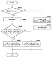
まず、CPU1701はステップS501にて、RAWデータファイル1707内の全RAWデータに対する符号化処理を終えたか否かを判定する。否の場合、CPU1701は、ステップS502にて、RAWデータファイル1707から、1フレーム分のRAWデータを入力し、RAM1703に格納する。そして、CPU1704はステップS503にて、RAM1703に格納されたRAWデータを参照して、式(1)に従って色差Co,Cg,Dgを算出する。CPU1704は、算出した色差Co,Cg、Dgを、RAM1703上に確保したCo,Cg,Dgの各プレーンの格納領域に格納する。この処理をRAWデータの全画素について実行することで、Co,Cg,Dgの各プレーンがRAM1703に格納される。CPU1701は、ステップS504にて、各プレーンの分散値VarCo,VarCg,VarDgを算出する。この算出は式(2)で示した通りである。
First, in step S501, the
次に、CPU1701はステップS505にて、次の条件を満たすか否かを判定する。VarCo>ThCo、又は、
VarCg>ThCg、又は、
VarDg>ThDg
CPU1701は、上記条件を満たさない場合には、着目RAWデータを第2プレーン群{Y,Co,Cg,Dg}に変換してから符号化するものとして決定する。Co,Cg,Dgプレーンは既にRAM1703に生成されている。それ故、CPU1701は、ステップS506にて、Yプレーンへの変換のみを行い、得られたYプレーンをRAM1703に格納する。そして、CPU1701は、ステップS507にて、まず、{Y,Co,Cg,Dg}の各プレーンの符号化データであることを表す識別情報を含むプレーンヘッダを符号化ファイル1708に追記する。そして、CPU1701は、第2プレーン群{Y,Co,Cg,Dg}の各プレーンをモノクロ多値画像としてJPEG2000に従って順に符号化し、その符号化データを符号化ファイル1708に追記する。なお、JPEG2000の符号化処理は公知であるので、その説明は省略する。
Next, in step S505, the
VarCg> ThCg, or
VarDg> ThDg
If the above condition is not satisfied, the
一方、先に説明した条件を満たす場合、CPU1701は、着目RAWデータを第1プレーン群{R,G0,G1,B}に変換してから符号化するものと決定する。そこで、CPU1701は、ステップS508にて、着目RAWデータから第1プレーン群{R,G0,G1,B}の各プレーンをRAM上に生成する。そして、ステップS509にて、CPU1701は、第1プレーン群{R,G0,G1,B}の符号化データであることを表す識別情報を含むプレーンヘッダを符号化ファイル1708に追記する。そして、CPU1701は、第1プレーン群{R,G0,G1,B}の各プレーンをモノクロ多値画像としてJPEG2000に従って順に順番に符号化し、その符号化データを符号化ファイル1708に追記する。
On the other hand, if the conditions described above are satisfied, the
以上の説明のように、コンピュータプログラムをコンピュータに実行させることでも、先に説明した第1の実施形態と等価の効果が得るRAW画像の符号化ファイルを生成することが可能となる。なお、第1の実施形態と同様に、ステップS505における「VarDg>ThDg」の条件から除外しても良い。 As described above, even if the computer program is executed by the computer, it is possible to generate an encoded file of a RAW image that has an effect equivalent to that of the first embodiment described above. Note that, similarly to the first embodiment, the condition may be excluded from the condition of “VarDg> ThDg” in step S505.
[第2の実施形態]
第2の実施形態を以下に説明する。本第2の実施形態も、第1の実施形態と同様に撮像装置に適用した例を説明する。撮像装置の構成は、第1の実施形態と同様、図15と同じである。よって、本第2の実施形態も画像処理部1509におけるRAWデータ符号化部を説明する。図6は、第2の実施形態であるRAWデータ符号化部のブロック構成図である。
[Second embodiment]
The second embodiment will be described below. An example in which the second embodiment is applied to an imaging device as in the first embodiment will be described. The configuration of the imaging device is the same as that of FIG. 15 as in the first embodiment. Therefore, the second embodiment also describes the RAW data encoding unit in the
第2の実施形態におけるRAWデータ符号化部は、第1の実施形態のそれとほぼ同様の構成である。ただし、第1の実施形態で存在していたフレームメモリ101、色差変換部108、特徴抽出部109は削除した。その代わり、第2の実施形態では演算部608を新設した。第2の実施形態でも、符号化対象として時系列に入力されるRAWデータで構成される動画像を符号化する例を説明する。なお、図6において、図1と同じ参照符号を付した構成は同じ機能をもつものとし、その説明は省略する。
The RAW data encoding unit according to the second embodiment has substantially the same configuration as that of the first embodiment. However, the
以下、第2の実施形態におけるプレーン判定部604の処理を、図7のフローチャートに従って説明すると共に、演算部608の機能も併せて説明する。
Hereinafter, the processing of the plane determination unit 604 according to the second embodiment will be described with reference to the flowchart of FIG. 7, and the function of the
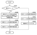
動画記録開始が操作部1504から指示されると、プレーン判定部604は、入力したRAWデータが、動画像記録の最初のフレームであるか否かを判定する(ステップS701)。最初のフレームであると判定した場合、入力したRAWデータを第2プレーン変換部103に供給する(ステップS702)。この結果、第2プレーン変換部103は、RAWデータから第2プレーン群{Y,Co,Cg,Dg}の各プレーンを生成することになる。また、このとき、プレーン判定部604は、第2プレーン群を選択したことを示す制御信号を符号列生成部113に供給する。そして、プレーン判定部604は、演算部608に対してアクティブする制御信号を出力する(ステップS703)。
When the start of moving image recording is instructed from the
上記の結果、最初のRAWデータについては、判定部111から符号化部112へ第2プレーン群{Y,Co,Cg,Dg}のプレーンが順に提供される。ウェーブレット変換部105は、Yプレーン、Coプレーン、Cgプレーン,Dgプレーンの順にウェーブレット変換を行い、プレーンごとに、サブバンLL,HL,LH,HHの係数データを量子化部106に供給する。この後の符号化処理は第1の実施形態で説明した通りである。
As a result, for the first RAW data, the planes of the second plane group {Y, Co, Cg, Dg} are sequentially provided from the
先に説明したように動画像の最初のRAWデータの符号化を行うとき、演算部608はアクティブに設定される。演算部608は、動画像記録の最初のRAWデータのYプレーンを除く、Coプレーン、Cgプレーン、Dgプレーンのウェーブレット変換で得られたサブバンドの変換係数データを用いた演算を行う。具体的には、演算部608はCoプレーンのウェーブレット変換で得られた、高周波成分を含むサブバンドHL,LH,HHの変換係数データの絶対値を累積加算していき、絶対和Wh_sumCoとして算出する。また、演算部608は、Cgプレーンのウェーブレット変換で得られた、高周波成分を含むサブバンドHL,LH,HHの変換係数データの絶対値和をWh_sumCgとして算出する。そして、演算部608は、Dgプレーンのウェーブレット変換で得られた、高周波成分を含むサブバンドHL,LH,HHの変換係数データの絶対値和をWh_sumDgとして算出する。これら絶対値和Wh_sumCo、Wh_sumCg、Wh_sumDgは、動画像記録の開始から2番目以降のRAWデータを、第1プレーン群{R,G0,G1,B}、第2プレーン群{Y,Co,Cg,Dg}のいずれに変換するかを決定するパラメータとして利用される。そのため、演算部608は算出した絶対値和Wh_sumCo、Wh_sumCg、Wh_sumDgをプレーン判定部604に供給する。
As described above, when encoding the first RAW data of a moving image, the
図7のフローチャートの説明に戻る。プレーン判定部604は入力したRAWデータが、動画像記録を開始してから2番目以降のフレームであると判定した場合、処理をステップS704に進める。このステップS704では、演算部608から供給された絶対値和Wh_sumCo、Wh_sumCg、Wh_sumDgを参照し、2番目以降のフレームのRAWデータに対する変換法を決定する。
The description returns to the flowchart of FIG. If the plane determination unit 604 determines that the input RAW data is the second and subsequent frames after the start of moving image recording, the process proceeds to step S704. In step S704, the conversion method for the RAW data of the second and subsequent frames is determined with reference to the absolute value sums Wh_sumCo, Wh_sumCg, and Wh_sumDg supplied from the
具体的には、プレーン判定部604は、色差ごとに予め用意した閾値ThwhCo.ThwhCg、ThwhDgを用いて次の条件を満たすか否かを判定する。
Wh_sumCo>ThwhCo、又は、
Wh_sumCg>ThwhCg、又は、
Wh_sumDg>ThwhDg
Specifically, the plane determination unit 604 determines the threshold value ThwhCo. It is determined whether or not the following condition is satisfied using ThwhCg and ThwhDg.
Wh_sumCo> ThwhCo, or
Wh_sumCg> ThwhCg, or
Wh_sumDg> ThwhDg
上記条件を満たす場合、プレーン判定部604は、2番目以降のフレームのRAWデータは、第1プレーン変換部102が変換処理するように設定する(ステップS705)。この結果、2番目以降のRAWデータについては、動画記録が終了するまで、第1プレーン変換部102で生成された第1プレーン群{R,G0,G1,B}に対するJPEG2000の符号化が行われることになる。
If the above condition is satisfied, the plane determination unit 604 sets the RAW data of the second and subsequent frames to be converted by the first plane conversion unit 102 (step S705). As a result, for the second and subsequent RAW data, JPEG2000 encoding is performed on the first plane group {R, G0, G1, B} generated by the first
また、上記条件を満たさない場合、プレーン判定部604は、2番目以降のフレームのRAWデータは、第2プレーン変換部103が変換処理するように設定する(ステップS706)。この結果、2番目以降のRAWデータについては、動画記録が終了するまで、第2プレーン変換部103で生成された第2プレーン群{Y,Co,Cg,Dg}に対するJPEG2000の符号化が行われることになる。
If the above condition is not satisfied, the plane determination unit 604 sets the RAW data of the second and subsequent frames to be converted by the second plane conversion unit 103 (step S706). As a result, for the second and subsequent RAW data, JPEG2000 encoding is performed on the second plane group {Y, Co, Cg, Dg} generated by the second
なお、2番目以降のフレームの符号化処理では、演算部608は機能はしなくて良い。それ故、プレーン判定部604は、上記絶対値和を演算部608から取得した場合、演算部608をインアクティブに設定するようにしても良い。
In the encoding processing of the second and subsequent frames, the
色差Co,Cg,Dgの各プレーンのウェーブレット変換の高周波成分を含むサブバンドの変換係数が大きい場合、色ノイズが発生する可能性が高い。そのため、上記のように、色ノイズが発生する可能性が高いRAWデータについては、第1プレーン群{R.G0,G1,B}への変換することとし、色ノイズの発生を抑えた符号化データを生成することができる。逆に言えば、色ノイズが発生する可能性が無い、もしくは無視できる場合には、RAWデータを第2プレーン群{Y,Co,Cg,Dg}へ変換することとし、解像感を高めつつ、符号化効率を上げることが可能になる。 When the conversion coefficient of the subband including the high-frequency component of the wavelet transform of each plane of the color differences Co, Cg, and Dg is large, there is a high possibility that color noise will occur. Therefore, as described above, the first plane group {R. G0, G1, B}, so that encoded data in which the occurrence of color noise is suppressed can be generated. Conversely, if there is no possibility or negligible occurrence of color noise, the RAW data is converted into the second plane group {Y, Co, Cg, Dg} to enhance the resolution. , It is possible to increase the coding efficiency.
なお、上記第2の実施形態によれば、先に説明した第1の実施形態と異なり、記録開始が指示された際の最初のフレームのRAWデータの特徴を用いて変換法を決定した。それ故、時間が経過するにつれて、変換法の判定の精度が次第に落ちる可能性がある。しかしながら、フレームメモリを必要とせず、第1の実施形態ほど、メモリアクセスが発生しないため、フレームレートの高い動画であってもリアルタイム処理を実現することが容易になる。 According to the second embodiment, different from the first embodiment described above, the conversion method is determined by using the characteristics of the RAW data of the first frame when recording start is instructed. Therefore, as the time elapses, the accuracy of the determination of the conversion method may gradually decrease. However, since a frame memory is not required and memory access does not occur as in the first embodiment, real-time processing can be easily realized even for a moving image having a high frame rate.
また、第2の実施形態によれば、動画像の記録の最初のフレームでは、第2プレーン群{Y、Co,Cg,Dg}に変換して符号化が行われ、動画像記録の2番目から最後のフレームまでは上記の条件に従った分類法が採用される。しかし、所定の時間間隔で、RAWデータの再評価を行うようにしても良い。この場合、その所定時間経過する度に、プレーン判定部104は演算部608をアクティブにし、上記判定処理を行えばよい。この結果、動画像記録中に、ユーザがパン、チルト操作、ズーミング操作等を行って、被写体が変化した場合であっても、その被写体の変化に追従したプレーン群への変換法が決定できる。なお、先に説明したように、第1の実施形態の変形例と同様、上記第2の実施形態の符号化処理をコンピュータプログラムで実現させても構わない。
According to the second embodiment, in the first frame of the recording of the moving image, the image is converted into the second plane group {Y, Co, Cg, Dg} and encoded, and the second frame of the moving image is recorded. The classification method according to the above conditions is adopted from to the last frame. However, the RAW data may be reevaluated at predetermined time intervals. In this case, each time the predetermined time elapses, the
[第3の実施形態]
第3の実施形態を以下に説明する。本第3の実施形態も、第1の実施形態と同様に撮像装置に適用した例を説明する。本第3の実施形態におけるRAWデータ符号化部の構成は、第2の実施形態の図6と同じである。ただし、本第3の実施形態におけるプレーン判定部604の判定処理、演算部608の演算処理は、第2の実施形態のそれと異なる。また、本第3の実施形態におけるウェーブレット変換部105は、入力したプレーンに対して2回ウェーブレット変換を行うものとする。
[Third Embodiment]
The third embodiment will be described below. An example in which the third embodiment is applied to an imaging apparatus as in the first embodiment will be described. The configuration of the RAW data encoding unit in the third embodiment is the same as that in FIG. 6 of the second embodiment. However, the determination process of the plane determination unit 604 and the calculation process of the
以下、図9のフローチャートに従って第3の実施形態におけるプレーン判定部604の処理と、第2の実施形態との差を説明する。 Hereinafter, the difference between the processing of the plane determination unit 604 in the third embodiment and the second embodiment will be described with reference to the flowchart of FIG.
動画記録開始が操作部1504から指示されると、RAWデータが判定部111に供給される。判定部111内のプレーン判定部604は、入力したRAWデータが、動画像記録の最初のフレームであるか否かを判定する(ステップS901)。最初のフレームであると判定した場合、入力したRAWデータを第2プレーン変換部103に供給し、第2プレーン群{Y,Co,Cg,Dg}の各プレーンを生成させる(ステップS702)。また、このとき、プレーン判定部604は、第2プレーン群を選択したことを示す制御信号を符号列生成部113に供給する。そして、プレーン判定部604は、演算部608に対してアクティブする制御信号を出力する(ステップS703)。
When start of moving image recording is instructed from the
先に説明したようにウェーブレット変換部105は着目プレーン(R,G0,G1,B,Y,Co,Cg,Dgのいずれかのプレーン)に対してウェーブレット変換を2回実行する。ウェーブレット変換を2回行うことで1つのフレームから、LL2、HL2,LH2,HH2,HL1,LH1,HH1の計7つのサブバンドが生成される。サブバンドの個数は増える点を除き、量子化部106、エントロピー符号化部107、符号列生成部113による符号化データの生成に至る処理は第2の実施形態と同じであるので、その説明は省略する。
As described above, the
本第3の実施形態における演算部608は、最初のフレームのRAWデータから得られたCo,Cg,Dgプレーンそれぞれの、LLサブバンドを除く、高周波成分を含むサブバンドを演算対象とする。
The
図10は、ウェ−ブレット変換を2回実行した場合のCoプレーン、Cgプレーン、Dgプレーンのウェ−ブレット変換後のサブバンドを示している。なお、ここで、L、Hの後についている数字は、階層レベルを示している。従って、例えばLL2は、水平方向、垂直方向ともに低周波領域の階層レベル2のサブバンドであることを示す。
FIG. 10 shows the sub-bands after the wavelet conversion of the Co plane, the Cg plane, and the Dg plane when the wavelet conversion is performed twice. Here, the numbers following L and H indicate the hierarchical levels. Therefore, for example, LL2 indicates that it is a subband of the
演算部608は、図10に示すように、動画像記録を開始してから最初のフレームのRAWデータの符号化時に、色差プレーン毎に、サブバンドLL2以外のサブバンドHL2,LH2、HH2,HL1,LH1,HH1の変換係数データの絶対値和を演算する。
As shown in FIG. 10, the
ここで、Coプレーンの階層レベル1のサブバンドHH1における変換係数データの絶対値和をWh_sumCoHH1とする。Coプレーンの階層レベル1のサブバンドHL1における変換係数データの絶対値和をWh_sumCoHL1とする。Coプレーンの階層レベル1のサブバンドLH1における変換係数データの絶対値和をWh_sumCoLH1とする。Coプレーンの階層レベル2のサブバンドHH2における変換係数データの絶対値和をWh_sumCoHH2とする。Coプレーンの階層レベル2のサブ場バンドHL2における変換係数データの絶対値和をWh_sumCoHL2とする。Coプレーンの階層レベル2のサブバンドLH2における変換係数データの絶対値和をWh_sumCoLH2とする。
Here, the sum of the absolute values of the transform coefficient data in the sub-band HH1 at the
同様に、Cgプレーンの階層レベル1のサブバンドHH1における変換係数データの絶対値和をWh_sumCgHH1とする。Cgプレーンの階層レベル1のサブバンドHL1における変換係数データの絶対値和をWh_sumCgHL1とする。Cgプレーンの階層レベル1のサブバンドLH1における変換係数データの絶対値和をWh_sumCgLH1とする。Cgプレーンの階層レベル2のサブバンドHH2における変換係数データの絶対値和をWh_sumCgHH2とする。Cgプレーンの階層レベル2のサブ場バンドHL2における変換係数データの絶対値和をWh_sumCgHL2とする。Cgプレーンの階層レベル2のサブバンドLH2における変換係数データの絶対値和をWh_sumCgLH2とする。
Similarly, the sum of the absolute values of the transform coefficient data in the sub-band HH1 of the
同様に、Dgプレーンの階層レベル1のサブバンドHH1における変換係数データの絶対値和をWh_sumDgHH1とする。Dgプレーンの階層レベル1のサブバンドHL1における変換係数データの絶対値和をWh_sumDgHL1とする。Dgプレーンの階層レベル1のサブバンドLH1における変換係数データの絶対値和をWh_sumDgLH1とする。Dgプレーンの階層レベル2のサブバンドHH2における変換係数データの絶対値和をWh_sumDgHH2とする。Dgプレーンの階層レベル2のサブ場バンドHL2における変換係数データの絶対値和をWh_sumDgHL2とする。Dgプレーンの階層レベル2のサブバンドLH2における変換係数データの絶対値和をWh_sumDgLH2とする。
Similarly, the sum of the absolute values of the transform coefficient data in the sub-band HH1 of the
図9のフローチャートの説明に戻る。プレーン判定部604は、入力したRAWデータが、動画像記録を開始してから2フレーム目以降であると判定した場合、処理をステップS904に進める。このステップS904にて、プレーン判定部604は、演算部608が最初のフレームの符号化時に算出したサブバンドの絶対値和(図10参照)を参照する。そして、プレーン判定部604は、次式(3)に従い、各色差毎の評価値Wh_sumCo、Wh_sumCg,Wh_sumDgを算出する。
Wh_sumCo=α1×Wh_sumCoHH1+β1×Wh_sumCoHL1+γ1×Wh_sumCoLH1
+α2×Wh_sumCoHH2+β2×Wh_sumCoHL2+γ2×Wh_sumCoLH2
Wh_sumCg=a1×Wh_sumCgHH1+b1×Wh_sumCgHL1+c1×Wh_sumCgLH1
+a2×Wh_sumCgHH2+b2×Wh_sumCgHL2+c2×Wh_sumCgLH2
Wh_sumDg=x1×Wh_sumDgHH1+y1×Wh_sumDgHL1+z1×Wh_sumDgLH1
+x2×Wh_sumDgHH2+y2×Wh_sumDgHL2+z2×Wh_sumDgLH2 …(3)
式中、α1、α2、β1、β2、γ1、γ2、a1、a2、b1、b2、c1、c2、x1、x2、y1、y2、z1、z2は予め設定された重み係数である。また、これら重み係数の関係は次の通りである。
α1<β1≒γ1、α2<β2≒γ2、α1<α2、β1<β2、γ1<γ2、
a1<b1≒c1、a2<b2≒c2、a1<a2、b1<b2、c1<c2、
x1<y1≒z1、x2<y2≒z2、x1<x2、y1<y2、z1<z2
上記のように、サブバンドHL、LHに対する重み係数は、サブバンドHHのそれより大きい。この理由は、サブバンドHL、LHは、各々垂直エッジ、水平エッジの性質を強く反映しているため、色ノイズに限らず、視覚的な画質劣化がより目立ち易くなるためである。同様に、階層レベルが小さいほうの重みを小さくしているのも、階層レベルが高いところで量子化を実施するほど、色ノイズに限定されず画質劣化が目立つためである。
Returning to the description of the flowchart of FIG. If the plane determination unit 604 determines that the input RAW data is after the second frame after starting moving image recording, the process proceeds to step S904. In step S904, the plane determination unit 604 refers to the sum of absolute values of subbands (see FIG. 10) calculated by the
Wh_sumCo = α1 × Wh_sumCoHH1 + β1 × Wh_sumCoHL1 + γ1 × Wh_sumCoLH1
+ α2 × Wh_sumCoHH2 + β2 × Wh_sumCoHL2 + γ2 × Wh_sumCoLH2
Wh_sumCg = a1 × Wh_sumCgHH1 + b1 × Wh_sumCgHL1 + c1 × Wh_sumCgLH1
+ a2 × Wh_sumCgHH2 + b2 × Wh_sumCgHL2 + c2 × Wh_sumCgLH2
Wh_sumDg = x1 × Wh_sumDgHH1 + y1 × Wh_sumDgHL1 + z1 × Wh_sumDgLH1
+ x2 × Wh_sumDgHH2 + y2 × Wh_sumDgHL2 + z2 × Wh_sumDgLH2 (3)
In the equation, α1, α2, β1, β2, γ1, γ2, a1, a2, b1, b2, c1, c2, x1, x2, y1, y2, z1, and z2 are preset weighting factors. The relationship between these weight coefficients is as follows.
α1 <β1 ≒ γ1, α2 <β2 ≒ γ2, α1 <α2, β1 <β2, γ1 <γ2,
a1 <b1 ≒ c1, a2 <b2 ≒ c2, a1 <a2, b1 <b2, c1 <c2,
x1 <y1 ≒ z1, x2 <y2 ≒ z2, x1 <x2, y1 <y2, z1 <z2
As described above, the weight coefficients for the sub-bands HL and LH are larger than those of the sub-band HH. The reason for this is that the subbands HL and LH strongly reflect the characteristics of the vertical edge and the horizontal edge, respectively, so that not only the color noise but also the visual image quality deterioration becomes more conspicuous. Similarly, the reason why the weight at the lower hierarchical level is set smaller is that the more the quantization is performed at the higher hierarchical level, the more noticeable the image quality is not limited to the color noise.
プレーン判定部604は、評価値Wh_sumCo、Wh_sumCg、Wh_sumDgを演算したら、処理をステップS905に進める。このステップS905にて、プレーン判定部604は、各々の評価値に対して予め設定された閾値ThwhCo、ThwhCg、ThwhDgを用いて、次に示す条件を満たすか否かを判定する(ステップS905)。
Wh_sumCo>WhwhCo、又は
Wh_sumCg>WhwhCg、又は
Wh_sumDg>WhwgDg
After calculating the evaluation values Wh_sumCo, Wh_sumCg, and Wh_sumDg, the plane determination unit 604 advances the process to step S905. In step S905, the plane determination unit 604 determines whether or not the following conditions are satisfied using thresholds ThwhCo, ThwhCg, and ThwhDg preset for each evaluation value (step S905).
Wh_sumCo> WhwhCo, or Wh_sumCg> WhwhCg, or Wh_sumDg> WhgDg
上記条件を満たす場合、プレーン判定部604は、2番目以降のフレームのRAWデータは、第1プレーン変換部102が変換処理するように設定する(ステップS906)。この結果、2番目以降のフレームのRAWデータについては、動画記録が終了するまで、第1プレーン変換部102で生成された第1プレーン群{R,G0,G1,B}に対するJPEG2000の符号化が行われることになる。
If the above condition is satisfied, the plane determination unit 604 sets the RAW data of the second and subsequent frames to be converted by the first plane conversion unit 102 (step S906). As a result, with respect to the RAW data of the second and subsequent frames, JPEG2000 encoding for the first plane group {R, G0, G1, B} generated by the first
また、上記条件を満たさない場合、プレーン判定部604は、2番目以降のフレームのRAWデータは、第2プレーン変換部103が変換処理するように設定する(ステップS907)。この結果、2番目以降のRAWデータについては、動画記録が終了するまで、第2プレーン変換部103で生成された第2プレーン群{Y,Co,Cg,Dg}に対するJPEG2000の符号化が行われることになる。
If the above condition is not satisfied, the plane determination unit 604 sets the RAW data of the second and subsequent frames to be converted by the second plane conversion unit 103 (step S907). As a result, for the second and subsequent RAW data, JPEG2000 encoding is performed on the second plane group {Y, Co, Cg, Dg} generated by the second
このように階層レベル、周波数領域に応じてウェーブレット係数絶対値総和に対して重みを付けることでより、RAWデータの第1プレーン群、第2プレーン群のいずれかに変換するかの判定精度を高めることが可能となる。 By assigning weights to the wavelet coefficient absolute value sum according to the hierarchical level and the frequency domain in this manner, the accuracy of determining whether to convert the RAW data into one of the first plane group and the second plane group is improved. It becomes possible.
また、第3の実施形態によれば、動画像の記録の最初のフレームでは、第2プレーン群{Y、Co,Cg,Dg}に変換して符号化が行われ、2番目以降で動画像記録の最後のフレームまでは上記の条件に従った分類法が採用される。しかし、第2の実施形態で説明したように、所定の時間間隔で、RAWデータの再評価を行うようにしても良い。この場合、その所定時間経過する度に、プレーン判定部104は演算部608をアクティブにし、上記判定処理を行えばよい。この結果、動画像記録中に、ユーザがパン、チルト操作を行って、被写体が変化した場合であっても、その被写体の変化に追従したプレーン群への変換法が決定できる。
Further, according to the third embodiment, in the first frame of the recording of the moving image, the image is converted into the second plane group {Y, Co, Cg, Dg} and encoded, and the second and subsequent planes are encoded. Until the last frame of the recording, a classification method according to the above conditions is adopted. However, as described in the second embodiment, the RAW data may be reevaluated at predetermined time intervals. In this case, each time the predetermined time elapses, the
なお、上記例ではウェーブレット変換を2回行う例であったが、3回でも良く、その回数はいくつでも構わない。また、先に説明したように、第1の実施形態の変形例と同様、上記第3の実施形態の符号化処理をコンピュータプログラムで実現させても構わない。 In the above example, the wavelet transform is performed twice, but may be performed three times, and the number may be any number. Further, as described above, similarly to the modification of the first embodiment, the encoding process of the third embodiment may be realized by a computer program.
[第4の実施形態]
第4の実施形態を説明する。本第4の実施形態も、第1の実施形態と同様に撮像装置に適用した例を説明する。撮像装置の構成は、第1の実施形態と同様、図15と同じである。よって、本第2の実施形態も画像処理部1509におけるRAWデータ符号化部を説明する。
[Fourth embodiment]
A fourth embodiment will be described. In the fourth embodiment, an example in which the fourth embodiment is applied to an imaging apparatus as in the first embodiment will be described. The configuration of the imaging device is the same as that of FIG. 15 as in the first embodiment. Therefore, the second embodiment also describes the RAW data encoding unit in the
図11は、第4の実施形態のRAWデータ符号化部のブロック構成図である。本第4の実施形態の、既に説明した第2の実施形態との相違は、プレーン判定部1104の処理内容と、圧縮率設定部1101を設けた点である。
FIG. 11 is a block diagram of a RAW data encoding unit according to the fourth embodiment. The fourth embodiment differs from the second embodiment already described in that the processing contents of the
圧縮率設定部1101は、ユーザーによる操作部1504からの指定したRAWデータの圧縮率をプレーン判定部1104および符号量制御部110に送信するものとする。以下、図12のフローチャートに従って、本第4の実施形態におけるプレーン判定部1104の処理を説明する。
The compression
動画像記録の開始指示を受けると、プレーン判定部1104は、ステップS1202にて圧縮率設定部1101より設定された圧縮率と、予め設定された閾値とを比較する。圧縮率が閾値より大きい場合、ユーザは符号化データファイルのサイズを小さくすることを望んでいることになる。それ故、プレーン判定部604は、RAWデータを第2プレーン変換部103が変換処理するように設定する(ステップS1203)。この結果、動画像の記録が終了するまで、第2プレーン変換部103で生成された第2プレーン群{Y,Co,Cg,Dg}に対するJPEG2000の符号化が行われることになる。
Upon receiving the moving image recording start instruction, the
一方、圧縮率が閾値以下であった場合、ユーザは色ノイズの発生の回避を重視していると見なす。それ故、プレーン判定部604は、RAWデータを第1プレーン変換部102が変換処理するように設定する(ステップS1204)。この結果、動画像の記録が終了するまで、第1プレーン変換部102で生成された第2プレーン群{R,G0,G1,B}に対するJPEG2000の符号化が行われることになる。
On the other hand, when the compression ratio is equal to or less than the threshold, it is considered that the user attaches importance to avoiding the occurrence of color noise. Therefore, the plane determination unit 604 sets the first
以上のように、本第4の実施形態によれば、ユーザが圧縮率が低くても画質が良いことを望んでいる場合には、RAWデータを第1プレーン群{R,G0,G1,B}への変換して符号化する。この結果、ユーザーが復号処理を経て現像後、カラーグレーディングする際の影響を少なくすることができる。一方、極端なカラーグレーディングを掛けることをしないユーザの場合には、圧縮率が高く設定できるので、解像感の低下による画質劣化を少なくしつつ、且つ、符号化ファイルのサイズも小さくできる。また、第4の実施形態では、記録対象は動画、静止画のいずれであっても構わない。また上記第4の実施形態の符号化処理をコンピュータプログラムで実現させても構わない。 As described above, according to the fourth embodiment, when the user desires that the image quality is good even if the compression ratio is low, the RAW data is converted into the first plane group {R, G0, G1, B}. Convert to} and encode. As a result, it is possible to reduce the influence of color grading after the user develops through the decoding process. On the other hand, in the case of a user who does not perform extreme color grading, the compression ratio can be set high, so that the quality of the encoded file can be reduced while the deterioration of the image quality due to the deterioration of the resolution is reduced. In the fourth embodiment, the recording target may be either a moving image or a still image. Further, the encoding processing of the fourth embodiment may be realized by a computer program.
[第5の実施形態]
第5の実施形態を説明する。本第5の実施形態も、第1の実施形態と同様に撮像装置に適用した例を説明する。撮像装置の構成は、第1の実施形態と同様、図15と同じである。よって、この第5の実施形態でも画像処理部1509におけるRAWデータ符号化部を説明する。
[Fifth Embodiment]
A fifth embodiment will be described. In the fifth embodiment, an example in which the fifth embodiment is applied to an imaging apparatus as in the first embodiment will be described. The configuration of the imaging device is the same as that of FIG. 15 as in the first embodiment. Therefore, also in the fifth embodiment, the RAW data encoding unit in the
図13は第5の実施形態におけるRAWデータ符号化部のブロック構成図である。第4の実施形態と異なる点は、プレーン判定部1304の判定処理と、被写界深度設定部1301が設けられた点である。また、これまで説明した実施形態における同じ参照符号で示される構成要素については特に説明しない。なお、第5の実施形態においても、第4の実施形態4と同様に、符号化対象を動画あるいは静止画(含む連写)であっても構わない。
FIG. 13 is a block diagram of a RAW data encoding unit according to the fifth embodiment. The difference from the fourth embodiment is that the determination processing of the
被写界深度設定部1301は、ユーザによる操作部1504に対する操作に従って撮像部1506に設定されたズーム倍率、絞り等によって決定されるF値を、プレーン判定部1304に設定するものとする。被写界深度が浅く背景がぼける場合には、符号化対象となるRAW画像データの多くの箇所で色差に限らず振幅が小さくなる。そのため、色ノイズは発生しない、もしくは発生したとしても無視できる程度に小さい。よって、被写界深度が浅い場合には、RAWデータを第2プレーン群{Y,Co,Cg,Dg}に変換して符号化する。一方、被写界深度が深い場合、色差の振幅が大きくなる可能性がある。そのため、RAWデータは第1プレーン群{R,G0,G1,B}に変換してから符号化することとする。以下、図14のフローチャートに従って、本第5の実施形態におけるプレーン判定部1304の処理を説明する。
The depth-of-
動画像記録の開始指示を受けると、プレーン判定部1304は、ステップS1402にて被写界深度設定部1301より設定されたF値と、予め設定された閾値とを比較する。F値が閾値より大きい場合、プレーン判定部1304は、RAWデータを第1プレーン変換部102が変換処理するように設定する(ステップS1403)。この結果、動画像の記録が終了するまで、第1プレーン変換部102で生成された第1プレーン群{R,G0,G1,B}に対するJPEG2000の符号化が行われることになる。一方、F値が閾値以下の場合、プレーン判定部1304は、RAWデータを第2プレーン変換部103が変換処理するように設定する(ステップS14034。この結果、動画像の記録が終了するまで、第2プレーン変換部103で生成された第2プレーン群{Y,Co,Cg,Dg}に対するJPEG2000の符号化が行われることになる。
Upon receiving the moving image recording start instruction, the
以上の結果、本第5の実施形態によれば、ユーザが設定した撮像する際の被写界深度に影響がある操作をした場合、ユーザは格別意識することなしに、撮像画像に適した符号化を行うことが可能になる。また上記第5の実施形態の符号化処理をコンピュータプログラムで実現させても構わない。 As a result, according to the fifth embodiment, when an operation that has an effect on the depth of field at the time of imaging set by the user is performed, the user is not required to be particularly aware of the code that is suitable for the captured image. Can be performed. Further, the encoding processing of the fifth embodiment may be realized by a computer program.
[第6の実施形態]
上記第1乃至第5の実施形態では、ベイヤ配列のRAWデータを符号化する際に、RAWデータを第1プレーン群{R,G0,G1,B}、第2プレーン群{Y,Co,Cg,Dg}のいずれに変換するかを決定し、符号化するものであった。
[Sixth Embodiment]
In the first to fifth embodiments, when encoding the RAW data in the Bayer array, the RAW data is divided into the first plane group {R, G0, G1, B} and the second plane group {Y, Co, Cg , Dg}, and encodes.
本第6の実施形態以降では、RAWデータを第2プレーン群{Y,Co,Cg,Dg}に変換し符号化する例を説明する。また、本第6の実施形態では、色差Co,Cg,Dhプレーンを解析することで、第2プレーン群{Y,Co,Cg,Dg}の各プレーンに割り当てる符号量を決定し、画質劣化と符号量の増大の抑制を行う。本第6の実施形態も、第1の実施形態と同様に撮像装置に適用した例を説明する。撮像装置の構成は、第1の実施形態と同様、図15と同じである。よって、本第2の実施形態も画像処理部1509におけるRAWデータ符号化部を説明する。
In the sixth and subsequent embodiments, an example in which RAW data is converted into a second plane group {Y, Co, Cg, Dg} and encoded will be described. In the sixth embodiment, by analyzing the color difference Co, Cg, and Dh planes, the code amount to be assigned to each plane of the second plane group {Y, Co, Cg, Dg} is determined, and image quality degradation and The increase of the code amount is suppressed. In the sixth embodiment, an example in which the sixth embodiment is applied to an imaging apparatus as in the first embodiment will be described. The configuration of the imaging device is the same as that of FIG. 15 as in the first embodiment. Therefore, the second embodiment also describes the RAW data encoding unit in the
図18に本第6の実施形態におけるRAWデータ符号化部のブロック構成図を示す。図示のように、本第6の実施形態におけるRAWデータ符号化部は、前処理部1801と符号化部1802で構成される。前処理部1801は、フレームメモリ101、第2プレーン変換部103、色差変換部108、特徴抽出部109を含む。また、符号化部1802は、ウェーブレット変換部105、量子化部106、エントロピー符号化部107、符号量制御部110、符号列生成部113を含む。第1の実施形態の図1における構成要素と実質的に同じ構成要素については同一参照符号を付し、その詳述は省略する。以下、第6の実施形態の処理を説明する。
FIG. 18 is a block diagram of a RAW data encoding unit according to the sixth embodiment. As illustrated, the RAW data encoding unit according to the sixth embodiment includes a
ユーザが操作部1504より動画記録の開始指示を行うと、ベイヤ配列のRAWデータが時系列にフレームメモリ101に格納されていく。第2プレーン変換部103は、先に示した式(1)に従って演算することで、フレームメモリ101に格納されたRAWデータを第2プレーン群{Y,Co,Cg,Dg}に変換し、各プレーンを順に符号化部1802に供給する。
When the user gives an instruction to start moving image recording from the
符号化部1802におけるウェーブレット変換部105は、第2プレーン変換部103から1つのプレーンが供給されるたびに、ウェーブレット変換する。そして、ウェーブレット変換部105は、その変換で得られたサブバンドLL、HL,LH,HHを量子化部104に供給する。量子化部106は、ウェーブレット変換部105から供給された各サブバンドの各変換係数データを、符号量制御部110から設定された目標符号量に従った量子化パラメータを用いて量子化する。そして、量子化部106は、量子化後の変換係数をエントロピー符号化部107に供給する。エントロピー符号化部107は、量子化部106で量子化された変換係数データをサブバンドごとにエントロピー符号化を行い、この符号化で得られた符号化データを符号列生成部113に供給する。符号列生成部113は、内部にバッファメモリを有し、エントロピー符号化部105から符号化データを一時的に格納し、各プレーンの符号化データを所定の順番に連結し、必要に応じてヘッダを生成し、RAM1503に確保された不図示の書き込み用バッファに出力する。
The
上記の説明からわかるように、RAWデータを変換して得られた第2プレーン群{Y,Co,Cg,Dg}の符号量は、符号量制御部110によって設定される目標符号量に依存する。そこで、各プレーンの目標符号量をどのようにして決定するかについて以下に更に詳しく説明する。
As can be understood from the above description, the code amount of the second plane group {Y, Co, Cg, Dg} obtained by converting the RAW data depends on the target code amount set by the code
色差変換部108は、符号化部1802にて着目RAWデータの符号化に先立って、その着目RAWデータから色差Co,Cg,Dgを算出する。色差変換部108は内部バッファを有し、算出した色差Co,Cg,Dgをその内部バッファに格納する。この結果、色差変換108の内部バッファには、Coプレーン、Cgプレーン、Dgプレーンが生成される。
The
特徴抽出部109は、色差変換部108の内部バッファに格納された3つの色差プレーンの分散値VarCo,VarCg,VarDgを式(2)に従って算出する。更に、特徴抽出部109は算出した各色差成分の分散値の加算値VarSumを算出し、算出した加算値VarSumを符号量制御部110に供給する。
VarSum=VarCo+VarCg+VArDg
The
VarSum = VarCo + VarCg + VArDg
符号量制御部106は、ユーザーが操作部1504を介して設定した圧縮率rate、RAW画像データのビット深度bit_depth、RAWデータの水平解像度w及び垂直解像度hから着目フレームの目標符号量pic_codeを決定する。具体的には、次式の通りである。
pic_code=w×h×bit_deth×rate/100 …(4)
The code
pic_code = w × h × bit_deth × rate / 100… (4)
符号量制御部106は、上記のようにして算出した着目フレームの目標符号量pic_codeと、特徴抽出部109から供給されたVarSumとから、次式(5)に従って、輝度Yプレーンに割り振る符号量Y_codeを決定する。
Varmax<VarSumのとき、Y_code=pic_code×α
Varmin≦VarSum≦Varmax、Y_code=pic_code×β/Var_Sum
VarSum<Varminのとき、Y_code=pic_code×γ …(5)
ここで、α、β、γは所定の係数、Varmax、Varminは所定の閾値である。なお、α<γであり、0<α<1かつ0<γ<1である。また、α=β/Varmax、γ=β/Varminである。
Based on the target code amount pic_code of the frame of interest calculated as described above and VarSum supplied from the
When Varmax <VarSum, Y_code = pic_code × α
Varmin ≦ VarSum ≦ Varmax, Y_code = pic_code × β / Var_Sum
When VarSum <Varmin, Y_code = pic_code × γ (5)
Here, α, β, and γ are predetermined coefficients, and Varmax and Varmin are predetermined thresholds. Note that α <γ, and 0 <α <1 and 0 <γ <1. Further, α = β / Varmax and γ = β / Varmin.
3つの色差プレーンに割り当てる目標符号量は、着目フレームの目標符号量pic_codeから輝度Yプレーンの目標符号量Y_codeを減じた残り量に基づき算出される。実施形態では、各色差プレーンの分散値が大きさに依存して割り当てる符号量を決定した。具体的には、符号量制御部106は、次式(6)に従って、色差Co,Cg,Dgの各プレーンに分配する符号量(目標符号量)Co_code、Cg_code、Dg_codeを決定する。
Co_code=(pic_code-Y_code)×VarCo/VarSum
Cg_code=(pic_code-Y_code)×VarCg/VarSum
Dg_code=(pic_code-Y_code)×VarDg/VarSum …(6)
The target code amount to be assigned to the three color difference planes is calculated based on the remaining amount obtained by subtracting the target code amount Y_code of the luminance Y plane from the target code amount pic_code of the frame of interest. In the embodiment, the code amount to which the variance value of each color difference plane is allocated depends on the size. Specifically, the code
Co_code = (pic_code-Y_code) × VarCo / VarSum
Cg_code = (pic_code-Y_code) × VarCg / VarSum
Dg_code = (pic_code-Y_code) × VarDg / VarSum (6)
ウェーブレット変換部105から着目フレームのYプレーンのサブバンドが量子化部106に供給される際、符号量制御部106は量子化部106に対して目標符号量Y_codeを設定する。この結果、量子化部106は、Yプレーンの各サブバンドを、設定された目標符号量Y_codeに対応するパラメータで示される量子化ステップに従って量子化することになる。同様に、ウェーブレット変換部105から着目フレームのCoプレーンのサブバンドが量子化部106に供給される際、符号量制御部106は、量子化部106に対して目標符号量Co_codeを設定する。この結果、量子化部106は、Coプレーンの各サブバンドを、設定された目標符号量Co_codeに対応するパラメータで示される量子化ステップに従って量子化することになる。他のCg,Dgプレーンについても同様である。
When the subband of the Y plane of the frame of interest is supplied from the
このように符号量を制御することで色差の分散値が大きく、符号化した際に色差の発生符号量、振幅が大きくなる場合には、該当する色成分に符号量を多く割り振ることができ、色ノイズの発生を抑えることができる。一方、色差の分散値が小さい場合には、輝度に割り振る符号量を多くなお、色ノイズを発生させることなく解像感を高め、主観画質の劣化を抑制することが可能になる。 By controlling the code amount in this way, the variance value of the color difference is large, and if the generated code amount of the color difference and the amplitude become large during encoding, a large code amount can be allocated to the corresponding color component, Generation of color noise can be suppressed. On the other hand, when the variance value of the color difference is small, it is possible to increase the code amount allocated to the luminance, increase the resolution without generating color noise, and suppress the deterioration of the subjective image quality.
なお、上記第6の実施形態では、色差Co、Cg、Dgの3つ全ての色差プレーンで分散値を算出したが、例えばCo、Cgのみにするなど、分散値を算出する色差プレーンの数を絞ってもよい。Co、Cgに絞るのは、Dgは、G0とG1の差分であり、色差としての性質よりG成分の斜め方向のエッジとしての性質が大きく、色ノイズ発生への影響が比較的小さいためである。この場合、VarSumは、VarCo、VarCgの和として算出し、数式(4)のβ、Varmax、VarminをVarDgを加算しないことを考慮して調整する。また、色差の符号量を求める際には、式(5)を用いる代わりにpic_codeとY_codeの差分を求め、3等分して各々の色差プレーンに割り振るなど別の方式で代用して決定すればよい。 In the sixth embodiment, the variance value is calculated for all three chrominance planes of the chrominance Co, Cg, and Dg. However, the number of chrominance planes for which the variance value is calculated is, for example, only Co and Cg. You may squeeze. The reason for narrowing down to Co and Cg is that Dg is the difference between G0 and G1, and the nature of the G component as a diagonal edge is larger than that of the color difference, and the influence on color noise generation is relatively small. . In this case, VarSum is calculated as the sum of VarCo and VarCg, and β, Varmax, and Varmin in Expression (4) are adjusted in consideration of not adding VarDg. Further, when calculating the code amount of the color difference, instead of using the equation (5), the difference between pic_code and Y_code is obtained, and the difference is determined by another method such as dividing into three and assigning to each color difference plane. Good.
[第6の実施形態の変形例]
上記第6の実施形態で説明した処理を、パーソナルコンピュータなどの汎用の情報処理装置で実行するアプリケーションプログラムで実現する例を、第6の実施形態の変形例として以下に説明する。
[Modification of Sixth Embodiment]
An example in which the processing described in the sixth embodiment is realized by an application program executed by a general-purpose information processing device such as a personal computer will be described below as a modification of the sixth embodiment.
第6の実施形態が適用する情報処理装置のブロック構成図は図17と同じであり、その説明は省略する。ただし、アプリケーションプログラム1706は、本第6の実施形態に従ってものとなる。
The block diagram of the information processing apparatus to which the sixth embodiment is applied is the same as that of FIG. 17, and a description thereof will be omitted. However, the
CPU1701がアプリケーションプログラム1706を実行した際の処理手順を図19のフローチャートに従って説明する。ここでも、HDD1704に格納されたRAWデータファイル1707に含まれる未符号化RAWデータを符号化し、符号化ファイル1708として生成する例を説明する。また、RAWデータファイル1707のファイルヘッダには、RAWデータの水平方向の解像度、垂直方向の解像度、及び1画素のビット数に関わるデータがセットされているものとする。また、ユーザからキーボード1709、マウス1710から、圧縮率が設定されているものとする。
A processing procedure when the
まず、CPU1701はステップS1901にて、RAWデータファイル1707内の全RAWデータに対する符号化処理を終えたか否かを判定する。否の場合、CPU1701は、ステップS1902にて、RAWデータファイル1707から、1フレーム分のRAWデータを入力し、RAM1703に格納する。そして、CPU1704はステップS1903にて、RAM1703に格納されらRAWデータを参照して、式(1)に従って輝度Y、色差Co,Cg、Dgを算出する。そして、CPU1704は、算出した輝度Yと3つ色差Co,Cg、Dgを、RAM1703上に確保したY,Co,Cg,Dgの各プレーンの格納領域に格納する。この処理をRAWデータの全画素について実行することで、RAM1703には、第2プレーン群{Y,Co,Cg,Dg}が生成される。CPU1701は、ステップS1904にて、RAM1703に格納されている色差Co,Cg,Dgのプレーンを参照し、式(2)に従い、各プレーンの分散値VarCo,VarCg,VarDgを算出する。また、CPU1701は、分散値VarCo,VarCg,VarDgの加算することでVarSumを算出する。
First, in step S1901, the
次に、CPU1701は、ステップS1905にて、着目フレームの目標符号量pic_codeを式(4)に従って算出する。そして、CPU1701は、ステップS1906にて輝度Yプレーンの目標符号量Y_codeを式(5)に従って算出する。また、CPU1701は、色差Co,Cg,Dgプレーンそれぞれの目標符号量Co_code,Cg_code,Dg_codeを式(6)に従って算出する。この後、CPU1701は、ステップS1907にて、RAM1703に既に格納されている輝度Yプレーンを目標符号量Y_codeとなるようJPEG2000に基づく符号化処理を行う。CPU1701は、符号化して得られた輝度Yプレーンの符号化データはRAM1703に一時的に格納する。同様に、CPU1701は、Co,Cg,Dgの色差プレーンについても、それぞれの目標符号量Co_code,Cg_code,Dg_codeとなるようにJPEG2000に基づく符号化処理を行う。生成された符号化データは、RAM1703に一時的に格納される。CPU1701は、生成された符号化データを所定の順に結合し、結合した符号化データを符号化ファイル1708に追記する。
Next, in step S1905, the
以上の説明のように、コンピュータプログラムをコンピュータに実行させることでも、先に説明した第6の実施形態と等価の効果が得るRAW画像の符号化ファイルを生成することが可能となる。 As described above, even when the computer program is executed by the computer, it is possible to generate an encoded file of a RAW image that has an effect equivalent to that of the sixth embodiment described above.
[第7の実施形態]
第7の実施形態を説明する。本第7の実施形態も、第1の実施形態と同様に撮像装置に適用した例を説明する。撮像装置の構成は、第1の実施形態と同様、図15と同じである。また、本第7の実施形態でも、第6の実施形態と同様に着目フレームの目標符号量から、第2プレーン群{Y,Co,Cg,Dg}に割り振る符号量を決定するものである。図20は第7の実施形態におけるRAWデータ符号化部のブロック構成図を示す。第6の実施形態における図18との違いは、フレームメモリ101、色差変換部108、特徴抽出部109がない点、並びに、演算部2001を設けた点である。それ以外は第6の実施形態と同じであるので、それらの説明は省略する。
[Seventh Embodiment]
A seventh embodiment will be described. An example in which the seventh embodiment is applied to an imaging device as in the first embodiment will be described. The configuration of the imaging device is the same as that of FIG. 15 as in the first embodiment. Also in the seventh embodiment, the code amount to be allocated to the second plane group {Y, Co, Cg, Dg} is determined from the target code amount of the frame of interest, as in the sixth embodiment. FIG. 20 is a block diagram of a RAW data encoding unit according to the seventh embodiment. The difference from FIG. 18 in the sixth embodiment is that the
演算部2001は、符号量制御110からの指示に従い、ウェーブレット変換部105が生成した色差CoのサブバンドHL,LH,HHの変換係数の合計値Wh_SumCoを算出する。また、演算部2001は、色差CgのサブバンドHL,LH,HHの変換係数の合計値Wh_SumCg、色差DgのサブバンドHL,LH,HHの変換係数の合計値Wh_SumDgも算出する。
The
以下、本第7の実施形態の処理手順を図21のフローチャートに従って説明する。 Hereinafter, the processing procedure of the seventh embodiment will be described with reference to the flowchart of FIG.
符号量制御部110は、着目RAWデータが動画像記録の開始してから最初のフレームであるか否かを判定する(ステップS2101)。着目RAWデータが最初のフレームである場合には、ステップS2102にて、符号量制御部110は、フレームの目標符号量pic_codeを式(4)に基づき算出する。そして、符号量制御部110は、ステップS2103にて、最初のフレームの各プレーンの目標符号量を次式(7)に従って算出する。
Y_code=pic_code×a
Co_code=pic_code×b
Cg_code=pic_code×c
Dg_code=pic_code×d …(7)
ここで、a,b,c,dは予め設定された係数であり、a+b+c+d=1である。つまり、係数a,b,c,dは各プレーンの割り振り比率を示している。最初のフレームの符号化時には、各プレーンの符号量を適切に決定する指標が存在しない。それ故、色ノイズが発生する確率を減らせるように、係数b、c、dは、大きめに設定するものとする。なお、ステップS2102,2103は、最初の符号化する現実のプレーンとは無関係に算出される点に注意されたい。符号量制御部110は、最初のプレーンの符号化を行うに当たって、式(7)により決定した各プレーンの目標符号量を量子化部106に設定する。これによって、動画像の最初のフレームのRAWデータの符号化処理が行われることになる。
The code
Y_code = pic_code × a
Co_code = pic_code × b
Cg_code = pic_code × c
Dg_code = pic_code × d (7)
Here, a, b, c, and d are preset coefficients, and a + b + c + d = 1. That is, the coefficients a, b, c, and d indicate the allocation ratio of each plane. When encoding the first frame, there is no index for appropriately determining the code amount of each plane. Therefore, the coefficients b, c, and d are set to be relatively large so that the probability of occurrence of color noise can be reduced. Note that steps S2102 and 2103 are calculated independently of the actual plane to be encoded first. When encoding the first plane, the code
また、符号量制御部110は、最初のフレームを符号化する際に、演算部2002に対してアクティブに設定する(ステップS2104)。このステップS2104の処理は、動画像の記録の2フレーム以降のRAWデータの符号化の際の、各プレーンの目標符号量を決定するための準備処理ということができる。このステップS2104の処理の結果、演算部2002は、最初のフレームの色差Coプレーンから得られたサブバンドHL,LH,HHの変換係数の合計値Wh_sumCoを算出する。また、同様に、演算部2002は、最初のフレームの色差Cgプレーンから得れたサブバンドHL,LH,HHの変換係数の合計値Wh_sumCgを算出する。また、同様に、演算部2002は、最初のフレームの色差Dgプレーンから得れたサブバンドHL,LH,HHの変換係数の合計値Wh_sumDgを算出する。
Further, when encoding the first frame, the code
符号量制御部110は、着目フレームが動画像記録を開始してから2番目のフレームであると判定した場合、処理をステップS2105に進める。このステップS2105において、符号量制御部110は、演算部2002から、最初のフレームから求めたWh_sumCo,Wh_sumCg,Wh_sumDgを取得し、それらの合計値Wh_sumを算出する。そして、符号量制御部110は、最初のフレームの符号化時に算出したpic_codeと、これらWh_sumCo,Wh_sumCg,Wh_sumDg、及びWh_sumに基づき、次式(8)に従って輝度Yプレーンの目標符号量Y_codeを算出する。
Whmax<Wh_Sumのとき、Y_code=pic_code×α
Whmin≦Wh_Sum≦Whmax、Y_code=pic_code×β/Vh_Sum
Wh_Sum<Whminのとき、Y_code=pic_code×γ …(8)
ここで、α、β、γは所定の係数、Whmax、Whrminは所定の閾値である。なお、α<γであり、0<α<1かつ0<γ<1である。また、α=β/Whmax、γ=β/Whminである。
If the code
When Whmax <Wh_Sum, Y_code = pic_code × α
Whmin ≦ Wh_Sum ≦ Whmax, Y_code = pic_code × β / Vh_Sum
When Wh_Sum <Whmin, Y_code = pic_code × γ (8)
Here, α, β, and γ are predetermined coefficients, and Whmax and Whrmin are predetermined thresholds. Note that α <γ, and 0 <α <1 and 0 <γ <1. Also, α = β / Whmax and γ = β / Whmin.
そして、符号量制御部110は、次式(9)に従い、色差Co,Cg,Dgのプレーンの目標符号量Co_code,Cg_code,Dg_codeを、それぞれのプレーンの絶対値の合計の割合に応じて算出する。
Co_code=(pic_code-Y_code)×Wh_SumCo/Wh_Sum
Cg_code=(pic_code-Y_code)×Wh_SumCg/Wh_Sum
Dg_code=(pic_code-Y_code)×Wh_SumDg/Wh_Sum …(9)
上記のようにして、符号量制御部110は、動画像の2フレーム以降の第2プレーン群{Y,Co,Cg,Dg}の各プレーンの目標符号量を決定する。従って、2フレーム以降のRAWデータを符号化する際、符号量制御部110は、上記のようにして決定した目標符号量を量子化部106に設定し、符号化処理を行わせることになる。
Then, the code
Co_code = (pic_code-Y_code) × Wh_SumCo / Wh_Sum
Cg_code = (pic_code-Y_code) × Wh_SumCg / Wh_Sum
Dg_code = (pic_code-Y_code) × Wh_SumDg / Wh_Sum (9)
As described above, the code
以上の結果、色差の高周波領域におけるウェーブレット係数絶対値総和が大きい場合、色差の振幅が大きく色ノイズが発生する可能性が高いと言える。かかる状況では、本第7の実施形態のように符号量を制御することで、各色差プレーンに割り振る符号量を多くし、色ノイズの発生を抑えることができる。一方、色差の高周波領域におけるウェーブレット係数絶対値総和が小さい場合は、輝度Yプレーンに多くの符号量を割り振ることで解像感を高め、主観的な画質を高めることが可能である。 As a result, when the sum of the absolute values of the wavelet coefficients in the high-frequency region of the color difference is large, it can be said that the amplitude of the color difference is large and color noise is likely to occur. In such a situation, by controlling the code amount as in the seventh embodiment, it is possible to increase the code amount allocated to each color difference plane and suppress the occurrence of color noise. On the other hand, when the sum of the absolute values of the wavelet coefficients in the high frequency region of the color difference is small, it is possible to increase the resolution and improve the subjective image quality by allocating a large amount of code to the luminance Y plane.
なお、第7の実施形態では、動画像の記録の最初のフレームについては、符号化対象画像の特徴そのものではなく、撮影開始時の画像の特徴を用いている。そのため、第6の実施形態と比較し、最初のフレームについては画質が劣る可能性がある。しかしながら、フレームメモリを必要とせず、メモリアクセスが発生しないため、フレームレートの高い動画であってもリアルタイム処理を実現することが容易になる。 In the seventh embodiment, for the first frame of the recording of a moving image, the feature of the image at the start of shooting is used instead of the feature itself of the image to be encoded. Therefore, the image quality of the first frame may be inferior to that of the sixth embodiment. However, since a frame memory is not required and no memory access occurs, real-time processing can be easily realized even for a moving image having a high frame rate.
また、第7の実施形態においてウェーブレット係数絶対値総和を演算するのは、撮影開始時のみであるが、フレーム符号化と並列して演算を行い、次のフレームの各プレーンの目標符号量設定に用いるようにしてもよい。また、第7の実施形態においても、第6の実施形態と同様に、色差プレーンをCo、Cgのみにするなどウェーブレット係数の絶対値総和を算出する色差プレーンの数を絞ってもよい。更に、上記第7の実施形態の符号化処理をコンピュータプログラムで実現させても構わない。 In the seventh embodiment, the sum of the wavelet coefficient absolute values is calculated only at the start of photographing. However, the calculation is performed in parallel with the frame coding, and the target code amount of each plane of the next frame is set. It may be used. Also in the seventh embodiment, as in the sixth embodiment, the number of color difference planes for calculating the sum of absolute values of wavelet coefficients may be reduced, for example, by setting only the color difference planes to Co and Cg. Further, the encoding process of the seventh embodiment may be realized by a computer program.
[第8の実施形態]
第8の実施形態を説明する。本第8の実施形態も、第1の実施形態と同様に撮像装置に適用した例を説明する。本第8の実施形態RAWデータ符号化部の構成図は第7の実施形態と同じである。ただし、ウェーブレット変換部105が1つのプレーンに対してウェーブレット変換を2回実行するものとする。また、演算部2002及び符号量制御部110の処理内容が第7の実施形態と異なる。なお、ウェーブレット変換を2回行うことで、ウェーブレット変換部105は、サブバンドLL,HL2,LH2,HH2,HL1,LH2,HH1の変換係数データを生成することになる。
[Eighth Embodiment]
An eighth embodiment will be described. In the eighth embodiment, an example in which the present embodiment is applied to an imaging apparatus as in the first embodiment will be described. The configuration of the RAW data encoding unit of the eighth embodiment is the same as that of the seventh embodiment. However, it is assumed that the
本第8の実施形態における演算部2002は、符号量制御部110からアクティブに設定されると、ウェーブレット変換部105で変換されたCo,Cg,Dgの色差プレーンの変換係数に対する演算を行う。具体的には、演算部2002は、サブバンドLL以外のサブバンドHL1,LH1,HH1,HL2,LH2,HH2それぞれの変換係数データの絶対値和を演算する。色差Coプレーンの各サブバンドの絶対値和をWh_sumCoHH1、Wh_sumCoHL1、Wh_sumCoLH1、Wh_sumCoHH2、Wh_sumCoHL2、Wh_sumCoLH2と表す。また、色差Cgプレーンの各サブバンドの絶対値和をWh_sumCgHH1、Wh_sumCgHL1、Wh_sumCgLH1、Wh_sumCgHH2、Wh_sumCgHL2、Wh_sumCgLH2とする。また、色差Dgプレーンの各サブバンドの絶対値和をWh_sumDgHH1、Wh_sumDgHL1、Wh_sumDgLH1、Wh_sumDgHH2、Wh_sumDgHL2、Wh_sumDgLH2とする。なお、これらの表記の、プレーンとサブバンドに対する関係は第3の実施形態と同じである。また、演算部2002は、上記演算結果である18個の合計値を符号量制御部110に供給する。
When set to be active by the code
以下、本第8の実施形態における符号量制御部110の処理手順を図22のフローチャートに従って説明する。
Hereinafter, the processing procedure of the code
符号量制御部110は、着目RAWデータが動画像記録を開始してから最初のフレームであるか否かを判定する(ステップS2201)。着目RAWデータが最初のフレームである場合には、符号量制御部110は、ステップS2202にて、着目フレームの目標符号量pic_codeを式(4)に基づき算出する。そして、符号量制御部110は、算出した目標符号量pic_codeから、各プレーンの目標符号量Y_code,Co_code,Cg_code,Dg_codeを式(7)に従って算出する(ステップS2203)。そして、符号量制御部110は、最初のプレーンの符号化を行うに当たって、上記のようにして算出した式(7)により決定した各プレーンの目標符号量を量子化部106に設定する。これによって、動画像の最初のフレームのRAWデータの符号化処理が行われることになる。
The code
また、符号量制御部110は、最初のフレームを符号化する際に、演算部2002をアクティブする(ステップS2204)。このステップS2204の処理は、動画像の記録の2フレーム以降のRAWデータの符号化の際の、各プレーンの目標符号量を決定するための準備処理と言うことができる。演算部2002がアクティブになると、最初のフレームから変換した輝度Yプレーン以外の、色差Co,Cg,Dgのプレーンから、先に示した18個の合計値を算出する。そして、演算部2002は演算した18個の合計値を符号量制御部110に供給することになる。
Further, when encoding the first frame, the code
符号量制御部110は、着目フレームが動画像記録を開始してから最初のフレームではないと判定した場合、処理をステップS2205に進める。このステップS2205において、符号量制御部110は、演算部2002から、最初のフレームから求めた18個の合計値に基づき式(3)に従って評価値Wh_sumCo、Wh_sumCg,Wh_sumDgを算出する。
If the code
そして、符号量制御部110は、算出した評価値Wh_sumCo、Wh_sumCg,Wh_sumDgから、その総和Wh_sum(=Wh_sumCo+Wh_sumCg+Wh_sumDg)を更に算出する。そして、符号量制御部110は、2フレーム目以降の輝度Yプレーンの目標符号量Y_codeを式(8)に従い算出する(ステップS2206)。そして、符号量制御部110は、色差Co,Cg,DGのプレーンの目標符号量Co_code,Cg_code,Dg_codeを式(9)に従って算出する。2フレーム以降のRAWデータを符号化する際、符号量制御部110は、上記のようにして決定した各プレーンの目標符号量を量子化部106に設定し、符号化処理を行わせることになる。
Then, the code
このように階層レベル、サブバンドに応じて、変換係数データの絶対値和に対して重みを付けることで、より精度を高めた符号量制御を行うことができる。なお、第8の実施形態において変換係数データの絶対値和を演算するのは、動画記録の最初のフレームのみとしたが、毎フレーム符号化を符号化する度に求めることで、次回のフレームの各プレーンの目標符号量設定に用いるようにしてもよい。また、第8の実施形態においても、第6の実施形態と同様に、ウェーブレット変換で得られた変換係数の絶対値和を算出する対象を、色差Co,Cg,Dgのプレーンのみに絞ってもよい。また上記第8の実施形態の符号化処理をコンピュータプログラムで実現させても構わない。 By weighting the sum of the absolute values of the transform coefficient data according to the hierarchical level and the subband in this manner, it is possible to perform the code amount control with higher accuracy. In the eighth embodiment, the sum of the absolute values of the transform coefficient data is calculated only for the first frame of the moving image recording. However, the sum is calculated every time each frame is encoded, so that the next frame is calculated. It may be used to set the target code amount of each plane. Also in the eighth embodiment, similarly to the sixth embodiment, the target for calculating the absolute value sum of the transform coefficients obtained by the wavelet transform is limited to only the planes of the color differences Co, Cg, and Dg. Good. Further, the encoding processing of the eighth embodiment may be realized by a computer program.
[第9の実施形態]
第9の実施形態を説明する。本第9の実施形態でも、第1の実施形態と同様に撮像装置に適用した例を説明する。撮像装置の構成は、第1の実施形態と同様、図15と同じである。よって、この第5の実施形態でも画像処理部1509におけるRAWデータ符号化部を説明する。
[Ninth embodiment]
A ninth embodiment will be described. Also in the ninth embodiment, an example in which the present invention is applied to an imaging apparatus as in the first embodiment will be described. The configuration of the imaging device is the same as that of FIG. 15 as in the first embodiment. Therefore, also in the fifth embodiment, the RAW data encoding unit in the
図23は第9の実施形態におけるRAWデータ符号化部のブロック構成図である。第7の実施形態と異なる点は、演算部2002がない点、被写界深度設定部2301が新設された点である。なお、第9の実施形態4においては、第7の実施形態と異なり、符号化対象を動画あるいは静止画連写時の静止画の何れであっても構わない。また、第9実施形態における被写界深度設定部2301および符号量制御部110の処理以外は第7の実施形態実と同様であるため、その説明を省略する。
FIG. 23 is a block diagram of a RAW data encoding unit according to the ninth embodiment. The difference from the seventh embodiment is that there is no calculation unit 2002 and that a depth of
被写界深度設定部2301は、ユーザによる操作部1504に対する操作に従って撮像部1506に設定されたズーム倍率、絞り等によって決定されるF値を、符号量制御部110に設定する。以下、係る点を踏まえ、本第9の実施形態における符号量制御部110の処理内容を図24のフローチャートに従って説明する。
The depth of
符号量制御部110は、ステップS2401にて、被写界深度設定部2301から設定されたF値を読み込む。そして、符号量制御部110は、ステップS2402にて、ユーザが操作部1504で設定した圧縮率rate、RAWデータのビット深さbit_depth、RAWデータの水平解像度w、垂直解像度hから、先に示した式(4)に基づき、1フレーム値の目標符号量pic_codeを算出する。
In step S2401, the code
そして、符号量制御部110は、ステップS2403にて、算出したpic_codeとF値とから、輝度プレーンの目標符号量Y_codeを次式(10)のように算出する。
α/F>βのとき、Y_code=pic_ccde×α/F
α/F≦βのとき、Y_code=pic_ccde×β …(10)
ここで、α、βは、所定の係数でありF値の最小値をFminとするとα/Fmin<1である。
In step S2403, the code
When α / F> β, Y_code = pic_ccde × α / F
When α / F ≦ β, Y_code = pic_ccde × β (10)
Here, α and β are predetermined coefficients, and when the minimum value of the F value is Fmin, α / Fmin <1.
符号量制御部1106は、次にステップS2404にて、pic_codeとY_codeの差分「pic_code−Y_code」の3等分を、各色差プレーンの目標符号量Co_code、Cg_code、Dg_codeに割り当てる。
Co_code={pic_code−Y_code}/3
Cg_code={pic_code−Y_code}/3
Dg_code={pic_code−Y_code}/3
Next, in step S2404, the code amount control unit 1106 allocates three equal parts of the difference “pic_code−Y_code” between pic_code and Y_code to the target code amounts Co_code, Cg_code, and Dg_code of each color difference plane.
Co_code = {pic_code-Y_code} / 3
Cg_code = {pic_code-Y_code} / 3
Dg_code = {pic_code-Y_code} / 3
被写界深度が浅く背景がぼける場合には、符号化対象となるRAW画像データの多くの箇所で色差に限らず振幅が小さくなるため、色ノイズが発生しづらい。従って、被写界深度が浅い場合には、輝度プレーンに多くの符号量を割り振り、解像感を高め、主観画質を高める。一方、被写界深度が深い場合には、色差の振幅が大きくなる可能性があるため、輝度に割り振る符号量を少なくし、色差プレーンにも多くの符号量を割り当てることで色ノイズの発生を抑制する。また上記第9の実施形態の符号化処理をコンピュータプログラムで実現させても構わない。 In the case where the depth of field is shallow and the background is blurred, not only the color difference but also the amplitude is reduced in many places of the RAW image data to be encoded, so that color noise hardly occurs. Therefore, when the depth of field is shallow, a large amount of code is allocated to the luminance plane to enhance the resolution and enhance the subjective image quality. On the other hand, when the depth of field is large, the amplitude of the color difference may increase, so that the amount of code allocated to the luminance is reduced, and the amount of code is also allocated to the color difference plane to reduce the occurrence of color noise. Suppress. Further, the encoding process of the ninth embodiment may be realized by a computer program.
(その他の実施例)
また、本発明は、以下の処理を実行することによっても実現される。即ち、上述した実施形態の機能を実現するソフトウェア(プログラム)を、ネットワーク又は各種記憶媒体を介してシステム或いは装置に供給し、そのシステム或いは装置のコンピュータ(またはCPUやMPU等)がプログラムを読み出して実行する処理である。
(Other Examples)
The present invention is also realized by executing the following processing. That is, software (program) that realizes the functions of the above-described embodiments is supplied to a system or apparatus via a network or various storage media, and a computer (or CPU, MPU, or the like) of the system or apparatus reads the program and reads the program. This is the process to be performed.
101…フレームメモリ、102…第1プレーン変換部102、103…第2プレーン変換部、104…プレーン判定部、105…ウェーブレット変換部、106…量子化部、107…エントロピー符号化部、108…色差変換部、109…特徴抽出部、110…符号量制御部、111…判定部、112…符号化部、113…符号列生成部
Reference Signs List 101: frame memory, 102: first
Claims (16)
複数のRAW画像データを時系列に入力する入力手段と、
前記RAW画像データを、R成分で構成されるRプレーン、G0成分で構成されるG0プレーン、G1成分で構成されるG1プレーン、及び、B成分で構成されるBプレーンの計4プレーンで構成される第1プレーン群に変換する第1の変換手段と、
RAW画像データを、輝度成分で構成される輝度プレーンとそれぞれが互いに異なる色差成分で構成される3つの色差プレーンとの計4プレーンで構成される第2プレーン群に変換する第2の変換手段と、
前記第1プレーン群または前記第2プレーン群を符号化する符号化手段と、
符号化対象のRAW画像データを、前記第1プレーン群または前記第2プレーン群のいずれに変換するかを決定し、前記決定されたプレーン群の各プレーンを前記符号化手段により符号化するように制御する制御手段とを有し、
前記制御手段は、
前記入力手段に入力される最初のRAW画像データについては、前記第2の変換手段で前記第2プレーン群に変換して符号化するように制御し、
前記入力手段に入力される2番目以降のRAW画像データについては、前記最初のRAW画像データに基づいて、前記第1プレーン群または前記第2プレーン群のいずれに変換するかを決定する
ことを特徴とする符号化装置。 An encoding device for encoding RAW image data having a Bayer array,
Input means for inputting a plurality of RAW image data in time series;
The RAW image data is composed of a total of four planes: an R plane composed of R components, a G0 plane composed of G0 components, a G1 plane composed of G1 components, and a B plane composed of B components. First conversion means for converting into a first plane group,
A second conversion unit configured to convert the RAW image data into a second plane group including a total of four planes including a luminance plane including a luminance component and three color difference planes including respective color difference components; ,
Encoding means for encoding the first plane group or the second plane group;
It is determined whether the RAW image data to be encoded is to be converted into the first plane group or the second plane group, and each plane of the determined plane group is encoded by the encoding means. possess and control means for controlling,
The control means includes:
The first RAW image data input to the input unit is controlled by the second conversion unit so as to be converted into the second plane group and encoded.
For the second and subsequent RAW image data input to the input means, it is determined which of the first plane group and the second plane group is to be converted based on the first RAW image data. Encoding device.
前記制御手段は、前記2番目以降のRAW画像データについて前記第1プレーン群または前記第2プレーン群のいずれに変換するかを、前記最初のRAW画像データの第2プレーン群に含まれるプレーンを前記符号化手段によりウェーブレット変換を実行ことにより取得した変換係数に基づいて決定する
ことを特徴とする請求項1に記載の符号化装置。 The encoding unit performs a wavelet transform, a quantization, and an encoding process on each plane of the plane group,
The control unit determines whether to convert the second or later RAW image data into the first plane group or the second plane group by determining a plane included in the second plane group of the first RAW image data. The coding apparatus according to claim 1 , wherein the coding apparatus determines the conversion coefficient based on a transform coefficient obtained by performing a wavelet transform by the coding unit.
前記3つの色差プレーンそれぞれの分散値を算出する算出手段と、
算出した分散値それぞれと、それぞれの色差に対して設定された閾値とを比較することで、少なくとも1つの色差プレーンの分散値が該当する閾値より大きいとする条件を満たすかどうかを判定する条件判定手段とを含み、
前記条件判定手段の判定結果が前記条件を満たすことを示す場合、前記RAW画像データを前記第1プレーン群に変換すると判定し、
前記条件判定手段の判定結果が前記条件を満たさないことを示す場合、前記RAW画像データを前記第2プレーン群に変換すると判定する
ことを特徴とする請求項1又は2に記載の符号化装置。 The control means includes:
Calculating means for calculating a variance value of each of the three color difference planes;
By comparing each of the calculated variance values with a threshold value set for each color difference, a condition determination is made to determine whether or not a condition that the variance value of at least one color difference plane is larger than the corresponding threshold value is satisfied. Means,
If the result of the determination by the condition determination means indicates that the condition is satisfied, it is determined that the RAW image data is to be converted to the first plane group;
When indicating that the determination result of the condition judging means does not satisfy the condition, the encoding device according to the RAW image data to claim 1 or 2, wherein the determining and converting into the second plane group.
前記3つの色差プレーンそれぞれをウェーブレット変換して得られた高周波成分を含むサブバンドの変換係数の絶対値和を、各色差の評価値として算出する算出手段と、
算出した評価値それぞれと、それぞれの色差に対して設定された閾値とを比較することで、少なくとも1つの色差の評価値が該当する閾値より大きいとする条件を満たすかどうかを判定する条件判定手段とを含み、
前記条件判定手段の判定結果が前記条件を満たすことを示す場合、前記RAW画像データを前記第1プレーン群に変換すると判定し、
前記条件判定手段の判定結果が前記条件を満たさないことを示す場合、前記RAW画像データを前記第2プレーン群に変換すると判定する
ことを特徴とする請求項1又は2に記載の符号化装置。 The control means includes:
Calculating means for calculating a sum of absolute values of transform coefficients of subbands including high-frequency components obtained by performing a wavelet transform on each of the three color difference planes as an evaluation value of each color difference;
Condition determining means for comparing each of the calculated evaluation values with a threshold set for each of the color differences to determine whether or not a condition that the evaluation value of at least one color difference is larger than the corresponding threshold is satisfied. And
If the result of the determination by the condition determination means indicates that the condition is satisfied, it is determined that the RAW image data is to be converted to the first plane group;
When indicating that the determination result of the condition judging means does not satisfy the condition, the encoding device according to the RAW image data to claim 1 or 2, wherein the determining and converting into the second plane group.
高周波成分を含むサブバンドHL,LH,HHごとに絶対値和を算出し、且つ、サブバンドごとに設定された重み係数を各サブバンドの絶対値和に乗じることで、1つの色差の前記評価値を算出することを特徴とする請求項4に記載の符号化装置。 The calculating means is provided for each color difference.
The sum of absolute values is calculated for each of the sub-bands HL, LH, HH including a high-frequency component, and the weighting coefficient set for each sub-band is multiplied by the sum of the absolute values of each sub-band. The encoding device according to claim 4 , wherein the value is calculated.
前記制御手段は、前記被写界深度が予め設定された閾値より大きい場合、前記RAW画像データを前記第1プレーン群に変換すると判定し、前記被写界深度が前記閾値以下である場合には前記RAW画像データを前記第2プレーン群に変換すると判定することを特徴とする請求項1に記載の符号化装置。 Further comprising setting means for setting the depth of field of the imaging means,
The control unit determines that the RAW image data is to be converted to the first plane group when the depth of field is larger than a preset threshold, and when the depth of field is equal to or smaller than the threshold. The encoding apparatus according to claim 1, wherein it is determined that the RAW image data is to be converted into the second plane group.
RAW画像データを、輝度成分で構成される輝度プレーンとそれぞれが互いに異なる色差成分で構成される3つの色差プレーンとの計4プレーンに変換する変換手段と、
RAW画像データの目標符号量を設定する設定手段と、
前記3つの色差プレーンのうちの少なくとも1つの色差プレーンを解析することで、前記設定手段で設定したRAW画像データの目標符号量から前記輝度プレーンに割り当てる量を決定し、且つ、前記目標符号量における、前記輝度プレーンに割り振った量を減じた残りの量を、各色差プレーンに分配して割り当てる割り当て手段と、
前記変換手段で変換して得られた輝度プレーン、及び3つの色差プレーンのそれぞれを、前記割り当て手段で割り当てた各プレーンに割り当てた符号量を目標符号量として符号化する符号化手段と
を有することを特徴とする符号化装置。 An encoding device for encoding RAW image data having a Bayer array,
Conversion means for converting the RAW image data into a total of four planes including a luminance plane composed of luminance components and three color difference planes each composed of mutually different color difference components;
Setting means for setting a target code amount of the RAW image data;
By analyzing at least one of the three color difference planes, an amount to be assigned to the luminance plane is determined from a target code amount of the RAW image data set by the setting means, and Allocating means for distributing and allocating the remaining amount obtained by subtracting the amount allocated to the luminance plane to each chrominance plane,
Coding means for coding each of the luminance plane and the three color difference planes obtained by the conversion by the conversion means, with a code amount allocated to each plane allocated by the allocation means as a target code amount. An encoding device characterized by the above-mentioned.
前記3つの色差プレーンそれぞれの分散値を算出し、当該3つの色差プレーンの分散値の合計値を算出する算出手段を有し、
前記算出手段が算出した分散値の合計値を予め設定された1つ以上の閾値とを比較することで、前記RAW画像データの目標符号量のうち前記輝度プレーンに割り当てる符号量を決定し、
前記3つの色差プレーンには、各色差プレーンの分散値の割合に応じた符号量を割り当てる
ことを特徴とする請求項8に記載の符号化装置。 The assigning means,
Calculating means for calculating a variance value of each of the three color difference planes and calculating a total value of the variance values of the three color difference planes;
By comparing the total value of the variance values calculated by the calculation unit with one or more preset threshold values, a code amount to be assigned to the luminance plane among the target code amounts of the RAW image data is determined.
The encoding apparatus according to claim 8 , wherein a code amount according to a ratio of a variance value of each of the color difference planes is assigned to the three color difference planes.
前記符号化手段は、符号化対象のプレーンをJPEG2000に従って符号化し、
前記割り当て手段は、
最初のRAW画像データについては、予め設定された比率に従って、前記RAW画像データの目標符号量を、前記輝度プレーン、前記3つの色差プレーンの符号量として割り当て、
2番目以降のRAW画像データについては、最初のRAW画像データを前記符号化手段で符号化する際のウェーブレット変換にて得られた各色差プレーンそれぞれのサブバンドHL,LH,HHの絶対値和の合計値と閾値とを比較することで、輝度プレーンに割り当てる符号量を決定し、
2番目以降のRAW画像データの色差プレーンについては、前記絶対値和の合計値に対する、各各色差プレーンの絶対値和の比率に従って割り当てる符号量を決定する
ことを特徴とする請求項8に記載の符号化装置。 Input means for inputting the RAW image data in time series,
The encoding means encodes a plane to be encoded according to JPEG2000,
The assigning means,
For the first RAW image data, a target code amount of the RAW image data is assigned as the code amounts of the luminance plane and the three color difference planes according to a preset ratio.
For the second and subsequent RAW image data, the sum of the absolute value sums of the subbands HL, LH, and HH of each of the color difference planes obtained by the wavelet transform when the first RAW image data is encoded by the encoding means. By comparing the total value and the threshold value, the code amount to be assigned to the luminance plane is determined,
For the second and subsequent color difference plane of the RAW image data, according to claim 8, characterized in that to determine the amount of codes to be allocated to the total value of the absolute value sum, according to the ratio of the absolute value sum of respective color difference plane Encoding device.
前記割り当て手段は、
前記被写界深度と予め設定された閾値とを比較することで、前記RAW画像データの目標符号量から前記輝度プレーンに割り当てる量を決定し、
前記目標符号量における、前記輝度プレーンに割り振った量を減じた残りの量を3等分した値を、前記3つの色差プレーンの目標符号量として判定する
ことを特徴とする請求項8に記載の符号化装置。 Further comprising setting means for setting the depth of field of the imaging means,
The assigning means,
By comparing the depth of field with a preset threshold, an amount to be assigned to the luminance plane is determined from a target code amount of the RAW image data,
In the target code amount, the remaining amount of 3 equally divided value obtained by subtracting the amount allocated to the luminance plane, according to claim 8, wherein the determining a target code amount of the three color difference plane Encoding device.
複数のRAW画像データを時系列に入力する入力工程と、
前記RAW画像データを、R成分で構成されるRプレーン、G0成分で構成されるG0プレーン、G1成分で構成されるG1プレーン、及び、B成分で構成されるBプレーンの計4プレーンで構成される第1プレーン群に変換する第1の変換工程と、
RAW画像データを、輝度成分で構成される輝度プレーンとそれぞれが互いに異なる色差成分で構成される3つの色差プレーンとの計4プレーンで構成される第2プレーン群に変換する第2の変換工程と、
前記第1プレーン群または前記第2プレーン群を符号化する符号化工程と、
符号化対象のRAW画像データを、前記第1プレーン群または前記第2プレーン群のいずれに変換するかを決定し、前記決定されたプレーン群の各プレーンを前記符号化工程により符号化するように制御する制御工程とを有し、
前記制御工程では、
前記入力工程で入力される最初のRAW画像データについては、前記第2の変換工程で前記第2プレーン群に変換して符号化するように制御し、
前記入力工程で入力される2番目以降のRAW画像データについては、前記最初のRAW画像データに基づいて、前記第1プレーン群または前記第2プレーン群のいずれに変換するかを決定する
ことを特徴とする符号化装置の制御方法。 A method for controlling an encoding device that encodes RAW image data having a Bayer array, comprising:
An input step of inputting a plurality of RAW image data in time series;
The RAW image data is composed of a total of four planes: an R plane composed of R components, a G0 plane composed of G0 components, a G1 plane composed of G1 components, and a B plane composed of B components. A first conversion step of converting into a first plane group,
A second conversion step of converting the RAW image data into a second plane group including a total of four planes including a luminance plane including a luminance component and three color difference planes each including a different color difference component; ,
An encoding step of encoding the first plane group or the second plane group;
It is determined whether the RAW image data to be encoded is to be converted into the first plane group or the second plane group, and each plane of the determined plane group is encoded by the encoding step. It has a control step of controlling,
In the control step,
The first RAW image data input in the input step is controlled to be converted into the second plane group and encoded in the second conversion step,
For the second and subsequent RAW image data input in the input step, it is determined which of the first plane group and the second plane group is to be converted based on the first RAW image data. The control method of the encoding device described below.
RAW画像データを、輝度成分で構成される輝度プレーンとそれぞれが互いに異なる色差成分で構成される3つの色差プレーンとの計4プレーンに変換する変換工程と、
RAW画像データの目標符号量を設定する設定工程と、
前記3つの色差プレーンのうちの少なくとも1つの色差プレーンを解析することで、前記設定工程で設定したRAW画像データの目標符号量から前記輝度プレーンに割り当てる量を決定し、且つ、前記目標符号量における、前記輝度プレーンに割り振った量を減じた残りの量を、各色差プレーンに分配して割り当てる割り当て工程と、
前記変換工程で変換して得られた輝度プレーン、及び3つの色差プレーンのそれぞれを、前記割り当て工程で割り当てた各プレーンに割り当てた符号量を目標符号量として符号化する符号化工程と
を有することを特徴とする符号化装置の制御方法。 A method for controlling an encoding device that encodes RAW image data having a Bayer array, comprising:
A conversion step of converting the RAW image data into a total of four planes including a luminance plane composed of luminance components and three color difference planes each composed of different color difference components;
A setting step of setting a target code amount of the RAW image data;
By analyzing at least one of the three color difference planes, an amount to be assigned to the luminance plane is determined from a target code amount of the RAW image data set in the setting step, and An allocation step of distributing and allocating the remaining amount obtained by subtracting the amount allocated to the luminance plane to each chrominance plane,
An encoding step of encoding each of the luminance plane and the three chrominance planes obtained by the conversion in the conversion step, with a code amount allocated to each plane allocated in the allocation step as a target code amount. A control method for an encoding device, comprising:
Priority Applications (2)
| Application Number | Priority Date | Filing Date | Title |
|---|---|---|---|
| JP2015211103A JP6663201B2 (en) | 2015-10-27 | 2015-10-27 | Image encoding apparatus and control method thereof, and computer program and storage medium |
| US15/299,048 US10097840B2 (en) | 2015-10-27 | 2016-10-20 | Image encoding apparatus, control method thereof, and storage medium |
Applications Claiming Priority (1)
| Application Number | Priority Date | Filing Date | Title |
|---|---|---|---|
| JP2015211103A JP6663201B2 (en) | 2015-10-27 | 2015-10-27 | Image encoding apparatus and control method thereof, and computer program and storage medium |
Publications (3)
| Publication Number | Publication Date |
|---|---|
| JP2017085319A JP2017085319A (en) | 2017-05-18 |
| JP2017085319A5 JP2017085319A5 (en) | 2018-11-29 |
| JP6663201B2 true JP6663201B2 (en) | 2020-03-11 |
Family
ID=58559482
Family Applications (1)
| Application Number | Title | Priority Date | Filing Date |
|---|---|---|---|
| JP2015211103A Expired - Fee Related JP6663201B2 (en) | 2015-10-27 | 2015-10-27 | Image encoding apparatus and control method thereof, and computer program and storage medium |
Country Status (2)
| Country | Link |
|---|---|
| US (1) | US10097840B2 (en) |
| JP (1) | JP6663201B2 (en) |
Families Citing this family (8)
| Publication number | Priority date | Publication date | Assignee | Title |
|---|---|---|---|---|
| US10410398B2 (en) * | 2015-02-20 | 2019-09-10 | Qualcomm Incorporated | Systems and methods for reducing memory bandwidth using low quality tiles |
| US10032252B2 (en) * | 2015-10-30 | 2018-07-24 | Canon Kabushiki Kaisha | Image processing apparatus, image capturing apparatus, image processing method, and non-transitory computer readable storage medium |
| JP6875802B2 (en) | 2016-08-22 | 2021-05-26 | キヤノン株式会社 | Image coding device and its control method, imaging device and program |
| JP7256629B2 (en) * | 2018-10-19 | 2023-04-12 | キヤノン株式会社 | Image encoding device and its control method and program |
| JP7242246B2 (en) | 2018-10-31 | 2023-03-20 | キヤノン株式会社 | Image encoding device, control method thereof, and program |
| JP7204441B2 (en) * | 2018-11-21 | 2023-01-16 | キヤノン株式会社 | IMAGING DEVICE, CONTROL METHOD AND PROGRAM THEREOF |
| JP7129326B2 (en) * | 2018-12-14 | 2022-09-01 | キヤノン株式会社 | IMAGING DEVICE, CONTROL METHOD AND PROGRAM THEREOF |
| JP2022122682A (en) * | 2021-02-10 | 2022-08-23 | キヤノン株式会社 | Image encoding device and control method thereof, and program |
Family Cites Families (6)
| Publication number | Priority date | Publication date | Assignee | Title |
|---|---|---|---|---|
| JP3864748B2 (en) | 2001-10-10 | 2007-01-10 | 株式会社ニコン | Image processing apparatus, electronic camera, and image processing program |
| JP4514203B2 (en) | 2004-06-11 | 2010-07-28 | キヤノン株式会社 | Motion vector detection apparatus and method |
| JP2005354610A (en) * | 2004-06-14 | 2005-12-22 | Canon Inc | Image processing apparatus, image processing method and image processing program |
| US7480417B2 (en) * | 2004-10-19 | 2009-01-20 | Microsoft Corp. | System and method for encoding mosaiced image data employing a reversible color transform |
| US8363717B2 (en) | 2005-05-17 | 2013-01-29 | Canon Kabushiki Kaisha | Image processing apparatus |
| CN104969545B (en) * | 2013-02-05 | 2018-03-20 | 富士胶片株式会社 | Image processing apparatus, camera device, image processing method and program |
-
2015
- 2015-10-27 JP JP2015211103A patent/JP6663201B2/en not_active Expired - Fee Related
-
2016
- 2016-10-20 US US15/299,048 patent/US10097840B2/en not_active Expired - Fee Related
Also Published As
| Publication number | Publication date |
|---|---|
| US20170118476A1 (en) | 2017-04-27 |
| US10097840B2 (en) | 2018-10-09 |
| JP2017085319A (en) | 2017-05-18 |
Similar Documents
| Publication | Publication Date | Title |
|---|---|---|
| JP6663201B2 (en) | Image encoding apparatus and control method thereof, and computer program and storage medium | |
| JP4686854B2 (en) | Image encoding device, electronic camera, and recording medium for image encoding program | |
| US20080298702A1 (en) | Fixed rate JPEG encoding | |
| JP2004112760A (en) | Image recording apparatus and image data selection method | |
| US9767542B2 (en) | Method and device for selecting an image dynamic range conversion operator | |
| US10163192B2 (en) | Image encoding apparatus and method of controlling the same | |
| JP2017216630A (en) | Image encoding device and its control method | |
| JP2020102704A (en) | Image encoding device, control method of the same, and program | |
| JP6792370B2 (en) | Image processing equipment, its control method, and computer programs | |
| US11140392B2 (en) | Image encoding apparatus, image decoding apparatus, control methods thereof, and non- transitory computer-readable storage medium | |
| JP7129326B2 (en) | IMAGING DEVICE, CONTROL METHOD AND PROGRAM THEREOF | |
| JP2016092589A (en) | Encoder and control method therefor | |
| US20070092148A1 (en) | Method and apparatus for digital image rudundancy removal by selective quantization | |
| JP6632752B2 (en) | Image encoding apparatus and method, program and storage medium | |
| EP2353294B1 (en) | Encoding method, encoding device, and encoding program for encoding interlaced image | |
| JP6465570B2 (en) | IMAGING DEVICE AND IMAGING DEVICE CONTROL METHOD | |
| JP4375662B2 (en) | Image processing apparatus, image processing method, program, information recording medium, and imaging apparatus | |
| JP2002252759A (en) | Image quantization method and device, and image coder utilizing them | |
| JP6512927B2 (en) | Image coding apparatus and control method thereof | |
| JP6775339B2 (en) | Image coding device and its control method | |
| JP6497981B2 (en) | Image coding apparatus and control method thereof | |
| JP2020092327A (en) | Image encoding device, image encoding method, and program | |
| JP7204441B2 (en) | IMAGING DEVICE, CONTROL METHOD AND PROGRAM THEREOF | |
| JP2019068385A (en) | Encoder, control method thereof, and control program, and imaging apparatus | |
| CN110418133B (en) | Method and apparatus for encoding image data |
Legal Events
| Date | Code | Title | Description |
|---|---|---|---|
| A521 | Request for written amendment filed |
Free format text: JAPANESE INTERMEDIATE CODE: A523 Effective date: 20181018 |
|
| A621 | Written request for application examination |
Free format text: JAPANESE INTERMEDIATE CODE: A621 Effective date: 20181018 |
|
| A977 | Report on retrieval |
Free format text: JAPANESE INTERMEDIATE CODE: A971007 Effective date: 20190624 |
|
| A131 | Notification of reasons for refusal |
Free format text: JAPANESE INTERMEDIATE CODE: A131 Effective date: 20190712 |
|
| A521 | Request for written amendment filed |
Free format text: JAPANESE INTERMEDIATE CODE: A523 Effective date: 20190903 |
|
| TRDD | Decision of grant or rejection written | ||
| A01 | Written decision to grant a patent or to grant a registration (utility model) |
Free format text: JAPANESE INTERMEDIATE CODE: A01 Effective date: 20200117 |
|
| A61 | First payment of annual fees (during grant procedure) |
Free format text: JAPANESE INTERMEDIATE CODE: A61 Effective date: 20200214 |
|
| R151 | Written notification of patent or utility model registration |
Ref document number: 6663201 Country of ref document: JP Free format text: JAPANESE INTERMEDIATE CODE: R151 |
|
| LAPS | Cancellation because of no payment of annual fees |