JP6662164B2 - Pressure pulse wave detecting device and biological information measuring device - Google Patents
Pressure pulse wave detecting device and biological information measuring device Download PDFInfo
- Publication number
- JP6662164B2 JP6662164B2 JP2016081392A JP2016081392A JP6662164B2 JP 6662164 B2 JP6662164 B2 JP 6662164B2 JP 2016081392 A JP2016081392 A JP 2016081392A JP 2016081392 A JP2016081392 A JP 2016081392A JP 6662164 B2 JP6662164 B2 JP 6662164B2
- Authority
- JP
- Japan
- Prior art keywords
- pulse wave
- pressure
- pressing
- unit
- pressure pulse
- Prior art date
- Legal status (The legal status is an assumption and is not a legal conclusion. Google has not performed a legal analysis and makes no representation as to the accuracy of the status listed.)
- Active
Links
Images


Classifications
-
- A—HUMAN NECESSITIES
- A61—MEDICAL OR VETERINARY SCIENCE; HYGIENE
- A61B—DIAGNOSIS; SURGERY; IDENTIFICATION
- A61B5/00—Measuring for diagnostic purposes; Identification of persons
- A61B5/02—Detecting, measuring or recording pulse, heart rate, blood pressure or blood flow; Combined pulse/heart-rate/blood pressure determination; Evaluating a cardiovascular condition not otherwise provided for, e.g. using combinations of techniques provided for in this group with electrocardiography or electroauscultation; Heart catheters for measuring blood pressure
- A61B5/021—Measuring pressure in heart or blood vessels
- A61B5/022—Measuring pressure in heart or blood vessels by applying pressure to close blood vessels, e.g. against the skin; Ophthalmodynamometers
- A61B5/0225—Measuring pressure in heart or blood vessels by applying pressure to close blood vessels, e.g. against the skin; Ophthalmodynamometers the pressure being controlled by electric signals, e.g. derived from Korotkoff sounds
-
- A—HUMAN NECESSITIES
- A61—MEDICAL OR VETERINARY SCIENCE; HYGIENE
- A61B—DIAGNOSIS; SURGERY; IDENTIFICATION
- A61B5/00—Measuring for diagnostic purposes; Identification of persons
- A61B5/02—Detecting, measuring or recording pulse, heart rate, blood pressure or blood flow; Combined pulse/heart-rate/blood pressure determination; Evaluating a cardiovascular condition not otherwise provided for, e.g. using combinations of techniques provided for in this group with electrocardiography or electroauscultation; Heart catheters for measuring blood pressure
- A61B5/021—Measuring pressure in heart or blood vessels
- A61B5/02108—Measuring pressure in heart or blood vessels from analysis of pulse wave characteristics
- A61B5/02116—Measuring pressure in heart or blood vessels from analysis of pulse wave characteristics of pulse wave amplitude
-
- A—HUMAN NECESSITIES
- A61—MEDICAL OR VETERINARY SCIENCE; HYGIENE
- A61B—DIAGNOSIS; SURGERY; IDENTIFICATION
- A61B5/00—Measuring for diagnostic purposes; Identification of persons
- A61B5/02—Detecting, measuring or recording pulse, heart rate, blood pressure or blood flow; Combined pulse/heart-rate/blood pressure determination; Evaluating a cardiovascular condition not otherwise provided for, e.g. using combinations of techniques provided for in this group with electrocardiography or electroauscultation; Heart catheters for measuring blood pressure
- A61B5/021—Measuring pressure in heart or blood vessels
- A61B5/02141—Details of apparatus construction, e.g. pump units or housings therefor, cuff pressurising systems, arrangements of fluid conduits or circuits
-
- A—HUMAN NECESSITIES
- A61—MEDICAL OR VETERINARY SCIENCE; HYGIENE
- A61B—DIAGNOSIS; SURGERY; IDENTIFICATION
- A61B5/00—Measuring for diagnostic purposes; Identification of persons
- A61B5/103—Detecting, measuring or recording devices for testing the shape, pattern, colour, size or movement of the body or parts thereof, for diagnostic purposes
- A61B5/11—Measuring movement of the entire body or parts thereof, e.g. head or hand tremor, mobility of a limb
-
- A—HUMAN NECESSITIES
- A61—MEDICAL OR VETERINARY SCIENCE; HYGIENE
- A61B—DIAGNOSIS; SURGERY; IDENTIFICATION
- A61B5/00—Measuring for diagnostic purposes; Identification of persons
- A61B5/68—Arrangements of detecting, measuring or recording means, e.g. sensors, in relation to patient
- A61B5/6801—Arrangements of detecting, measuring or recording means, e.g. sensors, in relation to patient specially adapted to be attached to or worn on the body surface
- A61B5/6813—Specially adapted to be attached to a specific body part
- A61B5/6824—Arm or wrist
-
- A—HUMAN NECESSITIES
- A61—MEDICAL OR VETERINARY SCIENCE; HYGIENE
- A61B—DIAGNOSIS; SURGERY; IDENTIFICATION
- A61B5/00—Measuring for diagnostic purposes; Identification of persons
- A61B5/68—Arrangements of detecting, measuring or recording means, e.g. sensors, in relation to patient
- A61B5/6801—Arrangements of detecting, measuring or recording means, e.g. sensors, in relation to patient specially adapted to be attached to or worn on the body surface
- A61B5/6843—Monitoring or controlling sensor contact pressure
-
- A—HUMAN NECESSITIES
- A61—MEDICAL OR VETERINARY SCIENCE; HYGIENE
- A61B—DIAGNOSIS; SURGERY; IDENTIFICATION
- A61B5/00—Measuring for diagnostic purposes; Identification of persons
- A61B5/72—Signal processing specially adapted for physiological signals or for diagnostic purposes
- A61B5/7235—Details of waveform analysis
-
- A—HUMAN NECESSITIES
- A61—MEDICAL OR VETERINARY SCIENCE; HYGIENE
- A61B—DIAGNOSIS; SURGERY; IDENTIFICATION
- A61B5/00—Measuring for diagnostic purposes; Identification of persons
- A61B5/72—Signal processing specially adapted for physiological signals or for diagnostic purposes
- A61B5/7271—Specific aspects of physiological measurement analysis
- A61B5/7275—Determining trends in physiological measurement data; Predicting development of a medical condition based on physiological measurements, e.g. determining a risk factor
-
- A—HUMAN NECESSITIES
- A61—MEDICAL OR VETERINARY SCIENCE; HYGIENE
- A61B—DIAGNOSIS; SURGERY; IDENTIFICATION
- A61B5/00—Measuring for diagnostic purposes; Identification of persons
- A61B5/74—Details of notification to user or communication with user or patient ; user input means
- A61B5/746—Alarms related to a physiological condition, e.g. details of setting alarm thresholds or avoiding false alarms
-
- A—HUMAN NECESSITIES
- A61—MEDICAL OR VETERINARY SCIENCE; HYGIENE
- A61B—DIAGNOSIS; SURGERY; IDENTIFICATION
- A61B5/00—Measuring for diagnostic purposes; Identification of persons
- A61B5/02—Detecting, measuring or recording pulse, heart rate, blood pressure or blood flow; Combined pulse/heart-rate/blood pressure determination; Evaluating a cardiovascular condition not otherwise provided for, e.g. using combinations of techniques provided for in this group with electrocardiography or electroauscultation; Heart catheters for measuring blood pressure
- A61B5/024—Detecting, measuring or recording pulse rate or heart rate
- A61B5/0245—Detecting, measuring or recording pulse rate or heart rate by using sensing means generating electric signals, i.e. ECG signals
Description
本発明は、圧脈波検出装置及び生体情報測定装置に関する。 The present invention relates to a pressure pulse wave detecting device and a biological information measuring device.
手首の橈骨動脈等の動脈が通る生体部位に圧力センサを直接接触させた状態で、この圧力センサにより検出される情報を用いて血圧、脈拍数、又は、心拍数等の生体情報を測定することのできる生体情報測定装置が知られている。この生体情報測定装置では、圧力センサと動脈との位置関係が圧脈波の検出精度に影響する。そこで、下記特許文献1〜5に示すように、生体部位と圧力センサとの位置調整を行うための構成が提案されている。
Measuring biological information such as blood pressure, pulse rate, or heart rate using information detected by the pressure sensor in a state where the pressure sensor is in direct contact with a body part through which an artery such as the radial artery of the wrist passes. There is known a biological information measuring device capable of performing the following. In this biological information measuring device, the positional relationship between the pressure sensor and the artery affects the detection accuracy of the pressure pulse wave. Then, as shown in the following
特許文献1に記載の生体情報測定装置は、生体部位に接触させる6×7=42個のセンサ群を有し、センサ群の各センサの出力が良好になるように、センサ群の動脈方向の傾きを手動で調整できる機構を有するものとなっている。
The biological information measuring device described in
特許文献2に記載の生体情報測定装置は、生体部位に接触させる6×7=42個のセンサ群を有し、センサ群の接触を手の動きに追従させるべく、センサ群が4分割され、各分割エリアの高さを調整可能な機構を有するものとなっている。
The biological information measuring device described in
特許文献3には、生体部位に接触させる圧力センサを有し、圧力センサを動脈と交差する方向に移動させる駆動部を有する生体情報測定装置が開示されている。
特許文献4には、生体部位に接触させる圧力センサ列を有し、圧力センサ列を圧力センサ列の押圧方向と交差する面内で回転させる駆動部を有する生体情報測定装置が開示されている。
特許文献5には、生体部位に接触させる圧力センサ列が複数並べて形成された押圧面を有し、この押圧面を、複数の圧力センサ列の配列方向と直交する方向に伸びる軸の周りに回転させる駆動部を有する生体情報測定装置が開示されている。
特許文献1,2に記載の装置は、センサ群の生体部位への接触状態を変えることはできるものの、利用者の手首の形に追従して接触状態が変化したり、手動で接触状態を変化させたりするものである。このため、脈波の検出精度を十分に考慮したセンサの位置決めを行うことはできない。
Although the devices described in
特許文献3,4,5に記載の装置は、圧力センサの出力が良好となるように圧力センサの位置を駆動するものであるため、脈波の検出精度を考慮した圧力センサの位置決めが可能である。しかし、圧力センサを生体部位に対して押圧し、その状態で圧力センサから出力される情報を用いて生体情報を測定する場合には、押圧力によって動脈の位置が変化することが想定される。特許文献3,4,5の装置では、このような位置変化に十分に追従することは難しい。
The devices described in
本発明は、上記事情に鑑みてなされたものであり、生体部位に接触させて用いる圧力検出素子の生体部位との接触状態を柔軟に変更して圧脈波検出精度を向上させることのできる圧脈波検出装置とこれを備える生体情報測定装置を提供することを目的とする。 SUMMARY OF THE INVENTION The present invention has been made in view of the above circumstances, and has been made in consideration of the above circumstances. A pressure detecting device that can be used in contact with a living body portion to flexibly change the contact state with the living body portion to improve pressure pulse wave detection accuracy. An object of the present invention is to provide a pulse wave detecting device and a biological information measuring device including the same.
本発明の圧脈波検出装置は、一方向に並ぶ複数の圧力検出素子からなる素子列が前記一方向と交差する方向に複数配列された押圧面を有する押圧部材と、前記一方向が生体の体表面下の動脈の伸びる方向と交差する状態で、前記押圧面を前記体表面に対し押圧する押圧機構と、前記押圧機構による前記押圧面の押圧方向に直交する2つの軸であって前記一方向に伸びる第一の軸と前記一方向と直交する第二の軸の各々の周りに前記押圧面を回転するための回転駆動機構と、前記押圧機構、前記回転駆動機構、及び、前記押圧部材を支持する支持部材と、前記支持部材を内蔵した状態で被測定者の手首に装着される筐体と、前記筐体内で前記支持部材を前記一方向に手動操作で移動させるための移動機構と、を備え、前記移動機構は、前記筐体の前記一方向及び前記押圧方向と直交する方向の端面のうち、前記筐体が手首に装着された状態で被測定者の中枢側にある端面に設けられた、前記一方向に延びるスリットと、前記スリットを貫通する凸部を介して前記支持部材に固定され、前記支持部材の前記一方向への移動操作を可能にする固定部材と、を備えるものである。 The pressure pulse wave detection device of the present invention is a pressing member having a pressing surface in which a plurality of element rows each including a plurality of pressure detecting elements arranged in one direction are arranged in a direction intersecting the one direction, and the one direction is a living body. A pressing mechanism for pressing the pressing surface against the body surface in a state intersecting the direction in which the artery below the body surface extends, and two axes orthogonal to the pressing direction of the pressing surface by the pressing mechanism. A rotation drive mechanism for rotating the pressing surface about each of a first axis extending in a direction and a second axis orthogonal to the one direction, the pressing mechanism, the rotation driving mechanism, and the pressing member A supporting member, a housing mounted on the wrist of the subject with the supporting member built therein, and a moving mechanism for manually moving the supporting member in the one direction in the housing. , wherein the moving mechanism, the housing Of the end faces in a direction perpendicular to the one direction and the pressing direction, a slit extending in the one direction, provided on an end face on the center side of the subject in a state where the housing is mounted on the wrist, A fixing member fixed to the support member via a convex portion penetrating the slit, and enabling a movement operation of the support member in the one direction .
本発明の生体情報測定装置は、上記圧脈波検出装置と、上記圧脈波検出装置に含まれる圧力検出素子により検出される圧脈波に基づいて生体情報を算出する生体情報算出部と、を備えるものである。 The biological information measurement device of the present invention, the pressure pulse wave detection device, a biological information calculation unit that calculates biological information based on the pressure pulse wave detected by the pressure detection element included in the pressure pulse wave detection device, It is provided with.
本発明によれば、生体部位に接触させて用いる圧力検出素子の生体部位との接触状態を柔軟に変更して圧脈波検出精度を向上させることのできる圧脈波検出装置とこれを備える生体情報測定装置を提供することができる。 ADVANTAGE OF THE INVENTION According to this invention, the pressure pulse wave detection apparatus which can change the contact state of the pressure detection element used in contact with a living body part with a biological part flexibly and can improve the pressure pulse wave detection accuracy, and the living body provided with this An information measuring device can be provided.
以下、本発明の実施形態について図面を参照して説明する。 Hereinafter, embodiments of the present invention will be described with reference to the drawings.
図1は、本発明の一実施形態を説明するための生体情報測定装置200の概略構成を示す側面図である。図1に示す生体情報測定装置200は、橈骨動脈が存在する被測定者の手首に装着して用いられる手首装着型の生体情報測定装置である。生体情報測定装置200は、動脈が体表面下に存在する生体部位に装着して用いるものであればよく、手首装着型に限定されるものではない。
FIG. 1 is a side view showing a schematic configuration of a biological
生体情報測定装置200は、筐体101及び筐体102と、筐体101と筐体102を連結するヒンジ部103とから構成される本体部と、本体部を手首に固定するためのベルト106と、を備える。ヒンジ部103により、筐体102は筐体101に対して回動自在に連結されている。
The biological
筐体101,102の内周面は手首Hの外形に沿った形状となっている。筐体101のヒンジ部103側とは反対側の端部が、筐体102に最も近付けられた状態で、筐体101と筐体102の間には、被測定者の手首Hが挿入可能な空間Kaが形成される。
The inner peripheral surfaces of the
空間Kaに手首Hが挿入された状態で、筐体101の一端と筐体102の一端がベルト106によって固定されることにより、生体情報測定装置200は手首Hに固定(装着)される。なお、筐体101と筐体102はヒンジ部103を介さずに一体化されたものであってもよい。
With the wrist H inserted into the space Ka, one end of the
筐体101は、生体情報測定装置200が手首Hに装着された状態で手首Hと対向する位置に設けられる圧脈波検出部100と、該状態において外周面に設けられる表示部13と、を備える。筐体101と圧脈波検出部100とにより、圧脈波検出装置が構成される。
The
図2は、生体情報測定装置200が被測定者の左手首に装着された状態を掌側から見た図である。図2に示すように、筐体101の外周面には表示部13が設けられており、掌側から表示部13を視認可能である。図3は、生体情報測定装置200が被測定者の左手首に装着された状態を手の甲側から見た図である。
FIG. 2 is a diagram showing a state in which the biological
図4は、図2,3に示す生体情報測定装置200の手首装着状態における圧脈波検出部100の構成を示す断面模式図である。図4では、生体情報測定装置200のうち圧脈波検出部100のみを図示している。
FIG. 4 is a schematic cross-sectional view showing the configuration of the pressure pulse
図5は、図4に示す圧脈波検出部100の拡大図である。図6は、図4に示す装着状態での圧脈波検出部100を被測定者の指先側から見た状態での断面模式図である。図7は、図4に示す装着状態での圧脈波検出部100を手首との接触部位側から見た図である。図4〜図7は、圧脈波検出部100を模式的に示したものであり、各部の寸法や配置等を限定するものではない。
FIG. 5 is an enlarged view of the pressure
圧脈波検出部100は、空気袋2を内蔵する筐体1と、空気袋2に固定された平板状の部材である平板部3と、平板部3に対して2軸回転機構5aにより2つの軸の各々を中心に回転可能に支持された回動部5と、回動部5の平板部3側とは反対側の平面に設けられたセンサ部6と、筐体1、空気袋2、平板部3、2軸回転機構5a、回動部5、及び、センサ部6を収容する収容部4と、備える。
The pressure pulse
筐体1、空気袋2、平板部3、及び、回動部5は、生体情報測定装置200が手首に装着された状態で、センサ部6の押圧面6bを生体部位(手首)の体表面に対して押圧する押圧機構を構成する。押圧機構は、センサ部6の押圧面6bを体表面に対して押圧できる機構であれば何でもよく、空気袋を用いたものには限定されない。
The
空気袋2は、図示しないポンプにより、内部の空気量が制御されることで、空気袋2に固定された平板部3を平板部3の表面(回動部5側の平面)に垂直な方向に移動させる。
The
図4に示す装着状態では、圧脈波検出部100に含まれるセンサ部6の押圧面6bが被測定者の手首の皮膚に接触する。この状態で空気袋2に注入される空気量が増えることで、空気袋2の内圧が増加し、センサ部6は手首下の橈骨動脈Tに向けて押圧される。以下、センサ部6による橈骨動脈Tへの押圧力は、空気袋2の内圧と等価であるとして説明する。
4, the
図7に示すように、センサ部6は、図4に示す装着状態において、装着部位に存在する橈骨動脈Tの伸びる方向Aと交差(図7の例では直交)する方向Bに並ぶ複数個の圧力検出素子6aからなる素子列60と、方向Bに並ぶ複数個の圧力検出素子7aからなる素子列70とを有する。素子列60と素子列70は方向Aに並べられている。
As illustrated in FIG. 7, in the mounting state illustrated in FIG. 4, the
各圧力検出素子6aと、この圧力検出素子6aと方向Bでの位置が同じ圧力検出素子7aとがペアを構成し、センサ部6には、このペアが方向Bに複数配列された構成となっている。圧力検出素子6aと圧力検出素子7aは、それぞれ、例えば、歪ゲージ抵抗式、半導体ピエゾ抵抗式、又は、静電容量式等の素子が用いられる。
Each
素子列60と素子列70に含まれる各圧力検出素子は同一平面上に形成されており、この平面が樹脂等の保護部材によって保護されている。各圧力検出素子が形成された平面と、この平面を保護する保護部材の表面とは平行になっており、この保護部材の表面が押圧面6bを構成する。
The pressure detecting elements included in the
圧力検出素子6a(7a)は、その配列方向が橈骨動脈Tと交差(略直交)するように橈骨動脈Tに対して押圧されることにより、橈骨動脈Tから発生して皮膚に伝達される圧力振動波、すなわち圧脈波を検出する。圧力検出素子6a(7a)から出力される圧力信号は、物との接触によって生じる直流成分と、圧力振動波によって生じる交流成分を含み、このうちの交流成分が圧脈波の信号となる。
The
各圧力検出素子6a(7a)の配列方向の間隔は、橈骨動脈T上に必要かつ充分な数が配置されるように充分小さくされている。各素子列560,70の長さは、橈骨動脈Tの径寸法より必要かつ充分に大きくされている。このように構成されたセンサ部6は、押圧部材を構成する。
The interval between the
図7に示すように、2軸回転機構5aは、空気袋2による平板部3の押圧方向に直交する2つの回転軸X,Yの各々を中心に回動部5を回転させるための機構である。2軸回転機構5a及び回動部5は、回転駆動機構を構成する。
As shown in FIG. 7, the two-axis
2軸回転機構5aは、平板部3の表面上に設定された互いに直交する2つの回転軸X,Yを有し、回転軸X,Yは、それぞれ、後述する回転駆動部10によって回転駆動される。
The
回転軸Yは、押圧面6bに形成された複数の圧力検出素子6a(7a)の配列方向に伸びる第一の軸である。回転軸Yは、図7の平面視において、素子列60と素子列70との間(図7の例では中間)に設定されている。
The rotation axis Y is a first axis extending in the arrangement direction of the plurality of
回転軸Xは、押圧面6bに形成された複数の圧力検出素子6a(7a)の配列方向と直交する方向に伸びる第二の軸である。回転軸Xは、図7の例では、素子列60と素子列70をそれぞれ均等に2分割する直線上に設定されている。
The rotation axis X is a second axis extending in a direction orthogonal to the direction in which the plurality of
回動部5が回転軸Xを中心に回転することで、押圧面6bは、回転軸Xの軸周りに回転する。また、回動部5が回転軸Yを中心に回転することで、押圧面6bは、回転軸Yの軸周りに回転する。
As the
圧脈波検出部100の収容部4は、筐体101に内蔵されており、筐体101によって方向Bに移動可能に支持されている。収容部4は、例えばコップ状の部材で構成され、この部材の中空部に、筐体1、空気袋2、平板部3、2軸回転機構5a、回動部5、及び、センサ部6が収容される。具体的には、収容部4は、中空部において筐体1を支持している。これにより、収容部4の移動に伴って、筐体1とこれに固定された空気袋2、平板部3、2軸回転機構5a、回動部5、及び、センサ部6が移動する。
The
収容部4は、これが方向Bに移動することで、筐体1、空気袋2、平板部3、及び、回動部5により構成される押圧機構と、2軸回転機構5a及び回動部5により構成される回転駆動機構と、センサ部6と、が一体となって方向Bに移動できるように、押圧機構、回転駆動機構、及び、センサ部6を支持する支持部材であればよい。例えば、収容部4は、筐体1を支持する平板状の部材によって、押圧機構、回転駆動機構、及び、センサ部6を一体的に支持する構成であってもよい。
The
図8は、図1に示す筐体101の収容部4が内蔵される部分の展開図を模式的に示した図である。
FIG. 8 is a diagram schematically showing a development view of a part of
図8(a)は、生体情報測定装置200を手首に装着した状態で筐体101を被測定者の抹消側(指先側)から見た側面図である。図8(b)は、生体情報測定装置200を手首に装着した状態で筐体101を押圧方向から見た上面図である。図8(c)は、生体情報測定装置200を手首に装着した状態で筐体101を被測定者の中枢側(肘側)から見た側面図である。図9は、図8に示すIX−IX線断面模式図である。
FIG. 8A is a side view of the
図8に示すように、筐体101の方向Aにおける端面のうち、生体情報測定装置200を手首に装着した状態で被測定者の中枢側(肘側)にある端面(以下、中枢側端面という)には、収容部4に固定された固定部材101Aが設けられている。固定部材101Aの表面には、凸部101Bが設けられている。
As shown in FIG. 8, of the end faces in the direction A of the
筐体101の中枢側端面には、方向Bに伸びるスリット101Cが形成されている。固定部材101Aの裏面には、図8(b)に示すように、スリット101Cを貫通する凸部101Dが形成されており、この凸部101Dが収容部4に固定されている。これにより、固定部材101Aは、スリット101Cを介して、方向Bに移動自在となっている。
A
図9に示すように、収容部4の方向Aにおける端面のうち、生体情報測定装置200が手首に装着された状態で被測定者の末梢側にある端面には、板バネ100bが固定されている。板バネ100bにはスライド部材100aが固定されている。スライド部材100aは、押圧方向(方向A及び方向Bに直交する方向)に長手の三角柱状の凸部を有する部材である。
As shown in FIG. 9, a
筐体101には、スライド部材100aの凸部が係合可能な凹部を図9の例では7つ有するスライドレール101aが形成されている。スライド部材100aは、板バネ100bによってスライドレール101aに向けて付勢されている。なお、図9(a)では、説明のために、スライド部材100aとスライドレール101aの間に隙間がある状態を図示している。
The
図9(a)に示す状態から、被測定者が凸部101Bに指をかけ、固定部材101Aに対して図9中の右方向に力を加えると、スライド部材100aの凸部は、スライドレール101aの凹部の斜面に沿って右方向に移動し、隣の凹部と係合する。この状態では、スライド部材100aの凸部は、板バネ100bによってスライドレール101aの凹部に付勢されて、図9(b)に示す状態となる。
From the state shown in FIG. 9A, when the subject places his or her finger on the
スライドレール101aの隣接する2つの凹部の間隔(凹部の底部同士の距離)は例えば1mm程度に設計される。これにより、収容部4は、図9(a)に示す位置を基準位置として、この基準位置から方向Bの一方の方向に1mmずつ計3mm動かすことができ、この基準位置から方向Bの他方の方向に1mmずつ計3mm動かすことができる。
The distance between two adjacent concave portions of the
なお、収容部4を移動させる際の最小単位として1mmは一例であり、これに限定されるものではない。また、収容部4を移動させることのできる距離は上記の例では6mmであるが、この数値も一例であり、これに限定されるものではない。
In addition, 1 mm is an example as a minimum unit at the time of moving the
このように、スライドレール101a、スライド部材100a、板バネ100b、固定部材101A、及び、凸部101Bによって、収容部4を筐体101内で方向Bに移動するための移動機構が構成される。なお、筐体101内で収容部4を方向Bに移動させる機構としては、図8及び図9に示したものに限らず、周知の機構を採用することができる。
As described above, the
図10は、図1に示す生体情報測定装置200のブロック構成を示す図である。
FIG. 10 is a diagram showing a block configuration of the biological
生体情報測定装置200は、圧脈波検出部100と、回転駆動部10と、空気袋駆動部11と、装置全体を統括制御する制御部12と、表示部13と、操作部14と、メモリ15と、を備える。
The biological
回転駆動部10は、圧脈波検出部100の2軸回転機構5aの各回転軸X,Yに接続されたアクチュエータである。回転駆動部10は、制御部12の指示にしたがい各回転軸X,Yを回転駆動して、押圧面6bを回転軸Xの軸周りに回転させたり、押圧面6bを回転軸Yの軸周りに回転させたりする。
The
空気袋駆動部11は、制御部12の指示のもと、空気袋2に注入する空気量(空気袋2の内圧)を制御する。
The air
表示部13は、測定された血圧値等の各種情報を表示するためのものであり、例えば液晶表示素子、有機電界発光表示素子、又は、電子ペーパ等により構成される。
The
操作部14は、制御部12に対する指示信号を入力するためのインターフェースであり、血圧測定を含む各種動作の開始を指示するためのボタン等により構成される。
The
メモリ15は、制御部12に所定の動作をさせるためのプログラム及び各種データを記憶するROM(Read Only Memory)、ワークメモリとしてのRAM(Random Access Memory)、及び、測定した血圧データ等の各種情報を記憶するフラッシュメモリ等を含む。
The
制御部12は、メモリ15のROMに記憶されたプログラムを実行することにより、押圧制御部、生体情報算出部、回転制御部、校正用データ生成部、及び、表示制御部として機能する。
The
押圧制御部は、空気袋駆動部11を制御して空気袋2内の空気量を調整することで、押圧面6bによる手首への押圧力を制御する。
The pressing control unit controls the pressing force on the wrist by the
生体情報算出部は、押圧面6bを橈骨動脈Tに押圧した状態で、押圧面6bに形成された圧力検出素子6a,7aにより検出される圧脈波に基づいて、橈骨動脈T内の第一の血圧値を算出する。
The biological information calculation unit, in a state where the
具体的には、生体情報算出部は、空気袋駆動部11によって橈骨動脈Tへの押圧力が変化(増加又は減少)させられていく過程で圧力検出素子6a,7aにより検出される圧脈波に基づいて、橈骨動脈T内の第一の血圧値を算出する。
Specifically, the biological information calculation unit performs the pressure pulse wave detected by the
校正データ生成部は、生体情報算出部により算出された第一の血圧値を用いて校正用データを生成する。 The calibration data generation unit generates calibration data using the first blood pressure value calculated by the biological information calculation unit.
回転制御部は、空気袋駆動部11によって橈骨動脈Tへの押圧力が増加させられていく過程で圧力検出素子6a,7aにより検出された圧脈波に基づいて、回転駆動部10による押圧面6bの回転の要否を判定する。そして、回転制御部は、回転が必要と判定したときに、回転駆動部10を制御して押圧面6bを回転させる。
The rotation control unit is configured to press the pressing surface of the
生体情報算出部は、橈骨動脈Tの一部を平坦に変形させるための最適押圧力で押圧面6bが橈骨動脈Tに押圧された状態で、圧力検出素子6a,7aにより1拍毎に検出される圧脈波を校正用データによって校正することで、1拍毎に橈骨動脈T内の第二の血圧値を算出する。
The biological information calculation unit detects each beat by the
表示制御部は、表示部13の表示制御を行う。
The display control unit controls display of the
以下、本実施形態の生体情報測定装置200の動作について説明する。本実施形態の生体情報測定装置200は、心臓の拍動の1拍毎に血圧値(SBP(Systolic Blood pressure)、いわゆる最高血圧と、DBP(Diastolic Blood pressure)、いわゆる最低血圧を測定してフラッシュメモリに記憶し、測定した血圧を表示部13に表示する連続血圧測定モードを有する。
Hereinafter, the operation of the biological
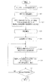
図11及び図12は、生体情報測定装置200の連続血圧測定モードにおける校正用データ生成までの動作を説明するためのフローチャートである。
FIGS. 11 and 12 are flowcharts for explaining the operation of the biological
なお、圧脈波検出部100の回動部5は、血圧測定の開始指示がなされる前の初期状態では、回転量が例えばゼロに設定され、押圧面6bが平板部3と平行になっているものとする。
In the initial state before the start instruction of the blood pressure measurement is given, the
操作部14に含まれる測定開始ボタンが押されて、血圧測定の開始指示がなされると(ステップS1:YES)、制御部12は、空気袋駆動部11を制御して空気袋2への空気の注入を開始し、押圧面6bによる手首への押圧力を増加させる(ステップS2)。血圧測定の開始指示がなされていない場合には、制御部12は、血圧測定の開始指示がなされるのを待機する。
When the measurement start button included in the
ステップS2の処理の後、制御部12は、橈骨動脈Tの閉塞が開始されるのに十分な時間が経過すると、空気袋駆動部11を制御して空気袋2への空気の注入を停止する。制御部12は、この状態で素子列60の各圧力検出素子6aにより検出された圧力信号と、素子列70の各圧力検出素子7aにより検出された圧力信号とに基づいて、素子列60と素子列70のいずれか一方に対する橈骨動脈Tの位置が最適であるか否かを判定する(ステップS3)。
After the process of step S2, the
任意の素子列に対する橈骨動脈Tの位置が最適であるとは、この素子列の方向Bの中央付近の下方に橈骨動脈Tが存在することを言う。 The optimal position of the radial artery T with respect to an arbitrary element row means that the radial artery T exists below the vicinity of the center in the direction B of this element row.
例えば、圧力検出素子が方向Bに46個配列された素子列を考える。この場合は、46個の圧力検出素子のうち、両端から数えてそれぞれ9番目の2つの圧力検出素子の間にある28個の圧力検出素子(素子列の中央付近の範囲内にある圧力検出素子)の下方に橈骨動脈Tが存在する場合に、この素子列に対する橈骨動脈Tの位置が最適であるとする。 For example, consider an element row in which 46 pressure detecting elements are arranged in the direction B. In this case, of the 46 pressure sensing elements, 28 pressure sensing elements (the pressure sensing elements located in the vicinity of the center of the element row) between the ninth two pressure sensing elements counted from both ends. If the radial artery T exists below the parentheses, it is assumed that the position of the radial artery T with respect to this element row is optimal.
具体的には、制御部12は、圧力信号のうちの交流成分の振幅値が閾値以上となる圧力検出素子を、橈骨動脈T上方に位置する圧力検出素子として判定する。そして、制御部12は、素子列60に含まれる圧力検出素子6aのうち、橈骨動脈T上方に位置すると判定した圧力検出素子6aの位置が、素子列60に対して予め設定されている中央付近の範囲内に全て入る場合に、素子列60に対する橈骨動脈Tの位置が最適であると判定する。同様に、制御部12は、素子列70に含まれる圧力検出素子7aのうち、橈骨動脈T上方に位置すると判定した圧力検出素子7aの位置が、素子列70に対して予め設定されている中央付近の範囲内に全て入る場合に、素子列70に対する橈骨動脈Tの位置が最適であると判定する。
Specifically, the
制御部12は、素子列60と素子列70の各々に対する橈骨動脈Tの位置が最適ではないと判定した場合(ステップS4:NO)には、空気袋駆動部11を制御して空気袋2内の空気を排出させ、初期状態に戻す(ステップS5)。そして、制御部12は、収容部4を方向Bに移動させることを指示する情報を表示部13に表示させて、収容部4の移動を被測定者に対して指示する(ステップS6)。制御部12は、ステップS6の後はステップS1に処理を戻す。
When the
ステップS6の処理により、例えば「動脈を正確に検出できません。センサユニットを移動させてから、再度、測定開始ボタンを押してください」といったメッセージが表示部13に表示される。この表示を見た被測定者は、図8(c)に示した凸部101B及び固定部材101Aを左右のどちらかに最小単位(上記の例では1mm)分、移動させる。
By the process in step S6, a message such as "The artery cannot be detected accurately. Move the sensor unit and then press the measurement start button again" is displayed on the
その後、被測定者が測定開始ボタンを押してステップS1の判定がYESになると、ステップS2〜ステップS4の処理が再び行われる。制御部12は、ステップS4において、素子列60と素子列70のいずれか一方に対する橈骨動脈Tの位置が最適であると判定した場合(ステップS4:YES)には、空気袋駆動部11を制御して空気袋2の空気を排気した後、再び空気袋2への空気の注入を開始し、押圧面6bによる手首への押圧力を増加させる(ステップS7)。
Thereafter, when the subject presses the measurement start button and the determination in step S1 is YES, the processes in steps S2 to S4 are performed again. When determining that the position of the radial artery T with respect to one of the
ステップS7で開始された押圧力の増加過程において、制御部12は、橈骨動脈Tの閉塞が開始されるのに十分な時間が経過した後の任意のタイミング(例えば周期的なタイミング)で、それまでに各圧力検出素子6aにより検出されてメモリ15に記憶された圧脈波群(圧脈波情報I1とする)のうち、検出時刻が新しい順に複数の圧脈波情報I1を取得する。また、制御部12は、上記任意のタイミングで、それまでに各圧力検出素子7aにより検出されてメモリ15に記憶された圧脈波群(圧脈波情報I2とする)のうち、検出時刻が新しい順に複数の圧脈波情報I2を取得する(ステップS8)。
In the process of increasing the pressing force started in step S7, the
制御部12は、ステップS8で取得した複数の圧脈波情報I1のうち、時刻t1に検出された圧脈波情報I1に含まれる圧脈波の例えば振幅の平均値Ave1を算出し、時刻t1よりも後の時刻t2に検出された圧脈波情報I1に含まれる圧脈波の振幅の平均値Ave2を算出する。また、制御部12は、ステップS8で取得した複数の圧脈波情報I2のうち、時刻t1に検出された圧脈波情報I2に含まれる圧脈波の振幅の平均値Ave3を算出し、時刻t2に検出された圧脈波情報I2に含まれる圧脈波の振幅の平均値Ave4を算出する。そして、制御部12は、同じ時刻に対して算出した平均値の比((Ave1/Ave3)と(Ave2/Ave4))を算出する。
The
制御部12は、複数のタイミングについて算出した比の変化に基づいて、回転駆動部10による回動部5の回転を行うべきか否かを判定する。つまり、制御部12は、押圧力の増加過程における複数タイミングで圧力検出素子6a,7aにより検出された圧脈波に基づいて、回動部5を回転させるか否かを判定する(ステップS9)。
The
例えば、複数のタイミングについて算出した比が単調増加している場合には、素子列70は橈骨動脈Tを閉塞する方向に向かっているが、素子列60は橈骨動脈Tを閉塞する方向に向かっていないと判定できる。このため、制御部12は、回動部5の回転は必要と判定する。
For example, when the ratio calculated for a plurality of timings is monotonically increasing, the element row 70 is in the direction of closing the radial artery T, but the
また、複数のタイミングについて算出した比が単調減少している場合には、素子列60は橈骨動脈Tを閉塞する方向に向かっているが、素子列70は橈骨動脈Tを閉塞する方向に向かっていないと判定できる。このため、制御部12は、回動部5の回転は必要と判定する。
When the ratio calculated for a plurality of timings is monotonically decreasing, the
また、複数のタイミングについて算出した比がほとんど変化していない場合には、素子列60,70が同じように橈骨動脈Tから高精度に圧脈波を検出していると判定できる。このため、制御部12は、回動部5の回転は不要と判定する。
When the ratios calculated for a plurality of timings hardly change, it can be determined that the
また、複数のタイミングについて算出した比が増減を繰り返している場合には、素子列60,70が橈骨動脈Tを十分に押圧できているか、一方の素子列だけが橈骨動脈Tを十分に押圧できていないのかの判定ができない。このため、制御部12は、回動部5の回転は不要と判定する。
If the ratio calculated for a plurality of timings repeatedly increases and decreases, the
このように、制御部12は、複数のタイミングについて算出した比の変動に基づいて回転の要否を判定する。なお、この比の代わりに、平均値Ave1(Ave2)と平均値Ave3(Ave4)の差分(符号を考慮した値)を用いてもよい。
As described above, the
図13(a)は、素子列70によって橈骨動脈Tが閉塞されているが、素子列60によっては橈骨動脈Tが閉塞されていない状態の例を示す図である。図13(a)の状態では、素子列60と橈骨動脈Tの距離が、素子列70と橈骨動脈Tの距離よりも大きくなっている。
FIG. 13A is a diagram illustrating an example of a state in which the radial artery T is closed by the element row 70 but the radial artery T is not closed by the
各圧力検出素子6aにより検出された圧脈波の振幅平均値を6Aとし、各圧力検出素子7aにより検出された圧脈波の振幅平均値を7Aとすると、図13の状態では、6Aと7Aの比である(6A/7A)は“1”よりも大きくなる。この状態では、素子列60を橈骨動脈Tに近づければ、(6A/7A)は1に近づく。
Assuming that the average amplitude value of the pressure pulse wave detected by each
そこで、制御部12は、ステップS9において回動部5の回転軸Y周りの回転が必要と判定したときは、最新時刻における(6A/7A)の値に応じて回動部5の回転軸Y周りの回転制御を行う(ステップS10)。
Therefore, when the
具体的には、制御部12は、(6A/7A)の値と回動部5の回転量との関係を示すデータテーブル(製品出荷前に実験的に求めてメモリ15に記憶しておく)を参照し、(6A/7A)の値に対応する回転量を読みだして、読みだした回転量を設定する。
Specifically, the
また、制御部12は、平均値6Aと平均値7Aのどちらが大きいかを判定し、平均値6Aが大きい場合には、素子列60と橈骨動脈Tとの距離を縮めるべく、回転軸Y周りの回動部5の回転方向を図13において反時計回りに設定する。
Further, the
制御部12は、平均値7Aが大きい場合には、素子列70と橈骨動脈Tとの距離を縮めるべく、回転軸Y周りの回動部5の回転方向を図13において時計回りに設定する。
When the average value 7A is large, the
制御部12は、このようにして設定した回転方向及び回転量によって回動部5を回転させる。これにより、図13(b)のように、押圧面6bと橈骨動脈Tとを平行にすることができ、橈骨動脈Tを広い範囲にわたって均等に圧扁した状態を得ることができる。
The
制御部12は、ステップS10の後と、ステップS9において回動部5の回転が不要と判定した場合には、ステップS11に処理を移行する。ステップS11において、制御部12は、橈骨動脈Tが閉塞されるのに十分な圧力(必要押圧力)に押圧力が到達したか否かを判定する。制御部12は、押圧力が必要押圧力に到達した場合(ステップS11:YES)に、空気袋駆動部11を制御して空気袋2への空気の注入を停止させる(ステップS12)。制御部12は、押圧力が必要押圧力に達していない場合はステップS8に処理を戻す。
After step S10, and when it is determined in step S9 that the rotation of the
ステップS12の後、制御部12は、ステップS7〜ステップS12の間において各圧力検出素子6aにより同時刻に検出された圧脈波の振幅と、その各圧力検出素子6aの押圧面6b上における位置との関係を示す振幅分布曲線、いわゆるトノグラムを求める。また、制御部12は、各圧力検出素子7aにより同時刻に検出された圧脈波の振幅と、その各圧力検出素子7aの押圧面6b上における位置との関係を示すトノグラムを求める。
After step S12, the
制御部12は、素子列60に対して生成したトノグラムを、この素子列60の識別情報、圧脈波の検出時刻、及びこの検出時刻における空気袋2による押圧方向への押圧力(空気袋2の内圧)と対応付けてメモリ15に記憶する。
The
同様に、制御部12は、素子列70に対して生成したトノグラムを、この素子列70の識別情報、圧脈波の検出時刻、及びこの検出時刻における空気袋2による押圧方向への押圧力と対応付けてメモリ15に記憶する。
Similarly, the
そして、制御部12は、メモリ15に記憶したトノグラムのデータを用いて、押圧面6bの手首への押圧中における橈骨動脈Tの方向Bへの移動量を算出する(ステップS13)。
Then, the
図14(a),(b)は、センサ部6による手首への押圧力を変化させていったときに、センサ部6の各圧力検出素子6aにより検出される圧脈波の振幅値の一例を示した図である。図14(a),(b)において、横軸は各圧力検出素子6aの方向Bでの位置を示し、縦軸は押圧力を示す。
FIGS. 14A and 14B show an example of the amplitude value of the pressure pulse wave detected by each
図14(a),(b)では、各位置にある圧力検出素子6aにより検出された圧脈波の振幅を、その大きさによって色分けしている。
14A and 14B, the amplitude of the pressure pulse wave detected by the
符号A1は、振幅が閾値TH1以上となっている部分である。符号A2は、振幅が閾値TH2以上閾値TH1未満となっている部分である。符号A3は、振幅が閾値TH3以上閾値TH2未満となっている部分である。符号A4は、振幅が閾値TH4以上閾値TH3未満となっている部分である。符号A5は、振幅が閾値TH4未満となっている部分である。なお、閾値TH1>閾値TH2>閾値TH3>閾値TH4である。 Symbol A1 is a portion where the amplitude is equal to or larger than the threshold value TH1. Symbol A2 is a portion where the amplitude is equal to or greater than threshold TH2 and less than threshold TH1. Symbol A3 is a portion where the amplitude is equal to or greater than threshold TH3 and less than threshold TH2. Symbol A4 is a portion where the amplitude is equal to or greater than threshold TH4 and less than threshold TH3. Symbol A5 is a portion where the amplitude is less than the threshold value TH4. Note that threshold TH1> threshold TH2> threshold TH3> threshold TH4.
図14(a)は、押圧力が増加していく過程で、閾値TH1以上の振幅の圧脈波を検出している圧力検出素子6aの位置がほぼ変化しない例を示している。これに対し、図14(b)は、押圧力が増加していく過程で、閾値TH1以上の振幅の圧脈波を検出している圧力検出素子6aの位置が左にずれていく例を示している。
FIG. 14A shows an example in which the position of the
図15は、圧脈波検出部100を手首に当てて、空気袋2によりセンサ部6を手首に向けて押圧していく状態を示す図である。図15において、符号TBは橈骨を示し、符号Kは腱を示す。
FIG. 15 is a diagram illustrating a state in which the pressure pulse
図15(a)に示すようにセンサ部6を手首に押圧していくと、図15(b)に示すように、橈骨動脈Tが方向Bに移動してしまうことがある。
When the
図15(b)のように、押圧中に橈骨動脈Tが方向Bに移動してしまうと、押圧中の圧脈波の振幅値の分布は図14(b)のようになる。つまり、閾値TH1以上の振幅値が初めて検出された押圧力における当該振幅値を検出した圧力検出素子6aの位置と、閾値TH1以上の振幅値が最後に検出された押圧力における当該振幅値を検出した圧力検出素子6aの位置とには大きなずれが生じることになる。
If the radial artery T moves in the direction B during the pressing as shown in FIG. 15B, the distribution of the amplitude values of the pressure pulse wave during the pressing becomes as shown in FIG. 14B. That is, the position of the
図14(a)の例では、閾値TH1以上の振幅値が初めて検出された押圧力における当該振幅値を検出した圧力検出素子6aの位置と、閾値TH1以上の振幅値が最後に検出された押圧力における当該振幅値を検出した圧力検出素子6aの位置とには大きなずれは生じていない。つまり、押圧力を増加させていく過程において、橈骨動脈Tが方向Bにほぼ移動することなく閉塞されていっていることが分かる。
In the example of FIG. 14A, the position of the
このように、押圧力が変化する過程におけるトノグラムの変化をみることで、橈骨動脈Tについて、方向Bでの位置変化を検出することができる。図15(b)に示す状態のまま、押圧力を増加させて橈骨動脈Tを閉塞すると、腱K等の生体組織の影響を受けて、正確なトノグラムを取得できない可能性が生じる。 As described above, the position change in the direction B with respect to the radial artery T can be detected by observing the change in the tonogram in the process of changing the pressing force. If the radial artery T is closed by increasing the pressing force in the state shown in FIG. 15B, there is a possibility that an accurate tonogram cannot be obtained due to the influence of the living tissue such as the tendon K.
そこで、制御部12は、押圧力とトノグラムの関係を示す図14のデータから、閾値TH1以上の振幅値が初めて検出された押圧力における当該振幅値を検出した圧力検出素子6aの位置と、閾値TH1以上の振幅値が最後に検出された押圧力における当該振幅値を検出した圧力検出素子6aの位置との差(つまり橈骨動脈Tの方向Bへの移動量)をステップS13にて算出し、算出した差が閾値THa以上か否かを判定する(ステップS14)。
Therefore, the
なお、制御部12は、素子列70に対して生成したトノグラムと押圧力の関係を示すデータに基づいて、橈骨動脈Tの方向Bへの移動量を算出し、算出した移動量を閾値THaと比較してもよい。
The
上記の移動量が閾値THa以上であれば(ステップS14:YES)、制御部12は、ステップS15において図14(b)の矢印で示したベクトルを求める。2つの位置の差が閾値THa未満であれば(ステップS14:NO)、ステップS16の処理が行われる。
If the movement amount is equal to or greater than the threshold value THa (step S14: YES), the
メモリ15には、図14に示したベクトルの向き及び大きさと、回動部5を回転軸X周りにどの方向にどの程度回転させるべきかを示す情報とを、予め実験的に求めて対応付けて記憶しておく。
In the
そして、制御部12は、求めたベクトルの大きさ及び向きに対応する回転方向及び回転量の情報をメモリ15から取得し、取得した情報を回転駆動部10に送信する。そして、回転駆動部10は、受信した情報にしたがって、図15(c)に示したように回動部5を回転させる(ステップS15)。
Then, the
ステップS15に続くステップS16では、制御部12が、空気袋駆動部11を制御して、空気袋2内の空気を排出させ、橈骨動脈Tへの押圧力の減少を開始する。
In step S16 following step S15, the
制御部12は、ステップS16で押圧力の減少を開始し、押圧力を最小値まで減少させた後、全ての圧力検出素子6a,7aの中から最適圧力検出素子を決定する。制御部12は、例えば、押圧力の減少過程において最大振幅の圧脈波を検出した圧力検出素子を最適圧力検出素子として決定する。
The
橈骨動脈Tが平坦になった部分の真上に位置する圧力検出素子によって検出される圧脈波は、橈骨動脈Tの壁の張力の影響がなく、最も振幅が大きくなる。また、この圧脈波は橈骨動脈T内の血圧値との相関が最も高い。このような理由により、最大振幅の圧脈波を検出した圧力検出素子を最適圧力検出素子として決定する。 The pressure pulse wave detected by the pressure detecting element located immediately above the flattened portion of the radial artery T has the largest amplitude without being affected by the tension of the wall of the radial artery T. The pressure pulse wave has the highest correlation with the blood pressure value in the radial artery T. For this reason, the pressure detecting element that has detected the pressure pulse wave having the maximum amplitude is determined as the optimum pressure detecting element.
なお、最大振幅の圧脈波を検出した圧力検出素子が複数ある場合もあり、その場合には、この複数の圧力検出素子を最適圧力検出素子として扱い、この複数の圧力検出素子の各々で検出された圧脈波の例えば平均を、この最適圧力検出素子により検出される圧脈波として扱えばよい。 In some cases, there are a plurality of pressure detecting elements that detect a pressure pulse wave having the maximum amplitude. In such a case, the plurality of pressure detecting elements are treated as optimal pressure detecting elements, and the detection is performed by each of the plurality of pressure detecting elements. For example, an average of the obtained pressure pulse waves may be treated as a pressure pulse wave detected by the optimum pressure detecting element.
そして、制御部12は、押圧力の減少過程でその最適圧力検出素子により検出された圧脈波から脈波包絡線データを生成する(ステップS17)。
Then, the
脈波包絡線データとは、センサ部6による橈骨動脈Tへの押圧力(空気袋2の内圧)と、その押圧力で最適圧力検出素子が橈骨動脈Tに押圧された状態で最適圧力検出素子により検出される圧脈波の振幅とを対応付けたデータである。
The pulse wave envelope data includes a pressing force (internal pressure of the air bladder 2) on the radial artery T by the
図16は、橈骨動脈Tへの押圧力の変化と、最適圧力検出素子により検出される圧脈波の変化の一例を示した図である。図16において、符号Pで示す直線が押圧力を示し、符号Mで示す波形が圧脈波を示している。図16の下段には、1つの圧脈波の拡大図を図示している。 FIG. 16 is a diagram illustrating an example of a change in the pressing force applied to the radial artery T and a change in the pressure pulse wave detected by the optimum pressure detecting element. In FIG. 16, a straight line indicated by a symbol P indicates a pressing force, and a waveform indicated by a symbol M indicates a pressure pulse wave. The lower part of FIG. 16 shows an enlarged view of one pressure pulse wave.
図16に示したように、圧脈波において、立ち上がり点での圧力を最小値Mminといい、立ち下がり点での圧力を最大値Mmaxという。圧脈波の振幅は、最大値Mmaxから最小値Mminを引いた値を言う。最大値Mmaxと最小値Mminは、それぞれ、圧脈波の形状を特定する情報の1つである。 As shown in FIG. 16, in the pressure pulse wave, the pressure at the rising point is called a minimum value Mmin, and the pressure at the falling point is called a maximum value Mmax. The amplitude of the pressure pulse wave is a value obtained by subtracting the minimum value Mmin from the maximum value Mmax. Each of the maximum value Mmax and the minimum value Mmin is one piece of information for specifying the shape of the pressure pulse wave.
図16に示したように、押圧力が減少を開始して橈骨動脈Tの閉塞状態が解除されると、最適圧力検出素子により検出される圧脈波は振幅が急激に大きくなり、その後、押圧力の減少に伴って図に示したように変化していく。制御部12は、ステップS17において、図16に示す押圧力と圧脈波の関係から、図17に示すような脈波包絡線データを生成する。
As shown in FIG. 16, when the pressing force starts to decrease and the occlusion state of the radial artery T is released, the amplitude of the pressure pulse wave detected by the optimum pressure detecting element rapidly increases, and thereafter, the pressing pulse wave increases. It changes as shown in the figure as the pressure decreases. In step S17, the
制御部12は、図17に示す脈波包絡線データを生成すると、生成した脈波包絡線データからSBPとDBPを算出する(ステップS18)。
When generating the pulse wave envelope data shown in FIG. 17, the
例えば、制御部12は、図17に示す脈波包絡線において、押圧力が減少を開始してから圧脈波振幅が急激に上昇を開始したときの押圧力、すなわち、押圧力が減少を開始してから最適圧力検出素子により検出される圧脈波振幅が動脈閉塞状態ではなくなったと判断できる閾値THbを初めて超えた時点での押圧力をSBPとして決定する。または、制御部12は、脈波包絡線データにおいて隣接する2つの振幅値の差分を算出し、この差分が閾値を超えた時点での押圧力をSBPとして決定する。
For example, in the pulse wave envelope shown in FIG. 17, the
更に、制御部12は、図17に示す脈波包絡線において、圧脈波振幅の最大値を脈圧(PP)とし、求めたSBP及びPPと、SBP−DBP=PPの関係式により、DBPを算出する。
Further, in the pulse wave envelope shown in FIG. 17, the
ステップS18の後、制御部12は、ステップS16以降の減圧過程で決定した最適圧力検出素子により検出された各圧脈波のいずれか(例えば、最大振幅となった圧脈波)の最大値Mmax及び最小値Mminと、ステップS18で算出したSBP及びDBPと、を用いて、後述する連続血圧測定時に用いる校正用データを生成してメモリ15に記憶する(ステップS19)。
After step S18, the
aを一次関数の傾き、bを一次関数の切片とすると、
SBP=a×Mmax+b ・・・(1)
DBP=a×Mmin+b ・・・(2)
の関係が成り立つ。
Let a be the slope of the linear function and b be the intercept of the linear function,
SBP = a × Mmax + b (1)
DBP = a × Mmin + b (2)
Holds.
制御部12は、式(1)と式(2)に、ステップS18で求めたSBP及びDBPと、図17の脈波包絡線における振幅が最大となった圧脈波の最大値Mmax及び最小値Mminとを代入して、傾きaと切片bを算出する。そして、算出した係数a,bと、式(1),(2)とを校正用データとしてメモリ15に記憶する。
The
図18は、本実施形態の生体情報測定装置200の連続血圧測定モードにおける連続血圧測定動作を説明するためのフローチャートである。
FIG. 18 is a flowchart for explaining the continuous blood pressure measurement operation in the continuous blood pressure measurement mode of the biological
連続血圧測定モードが設定され、血圧測定の開始指示がされると、まず、図11及び図12に示したステップS1〜ステップS16と同じ処理が行われる(ステップS20)。その後、押圧力が最小値に達すると、制御部12は、空気袋駆動部11を制御し、空気袋2の内圧を上昇させて、押圧面6bによる手首への押圧力を増加させる(ステップS21)。
When the continuous blood pressure measurement mode is set and an instruction to start blood pressure measurement is issued, first, the same processing as steps S1 to S16 shown in FIGS. 11 and 12 is performed (step S20). Thereafter, when the pressing force reaches the minimum value, the
次に、制御部12は、各圧力検出素子6a,7aのうち、押圧力の増加過程において最大振幅の圧脈波を検出した圧力検出素子を最適圧力検出素子として決定する。また、制御部12は、この最大振幅の圧脈波が検出された時点での空気袋2の内圧を最適押圧力として決定する(ステップS22)。
Next, the
次に、制御部12は、空気袋2の内圧を解放して初期状態に戻し(ステップS23)、その後、空気袋2の内圧をステップS22で決定した最適押圧力まで上昇させて、この最適押圧力を保持する(ステップS24)。
Next, the
次に、制御部12は、最適押圧力で押圧面6bが手首に押圧された状態で、ステップS22で決定した最適圧力検出素子により検出される圧脈波を取得する(ステップS25)。
Next, the
そして、制御部12は、取得した1つの圧脈波を、図12のステップS19で生成した校正用データを用いて校正して、第二の血圧値であるSBP及びDBPを算出し、算出したSBP及びDBPを表示部13に表示させる(ステップS26)。
Then, the
具体的には、制御部12は、ステップS25で取得した圧脈波の最大値Mmaxと、ステップS19で算出した係数a,bを上述した式(1)に代入してSBPを算出し、ステップS25で取得した圧脈波の最小値Mminと、ステップS19で算出した係数a,bを上述した式(2)に代入してDBPを算出する。制御部12は、連続血圧測定の終了指示があれば(ステップS27:YES)処理を終了し、終了指示がなければ(ステップS27:NO)、ステップS25に処理を戻す。
Specifically, the
以上のように、生体情報測定装置200によれば、押圧面6bが、回転軸Xと回転軸Yの各々周りに回転可能に構成されているため、センサ部6の生体部位との接触状態を柔軟に変更して圧脈波の検出精度を向上させることができる。
As described above, according to the biological
また、生体情報測定装置200によれば、素子列60又は素子列70に対する橈骨動脈Tの位置が最適な状態で、図11のステップS7以降の処理を行うことができる。このため、多くの圧力検出素子によって橈骨動脈Tから圧脈波を検出することができる状態でステップS8以降の処理を行うことができ、図11のステップS9における回転の要否判定、図11のステップS10における回動部5の回転軸Y周りの回転制御、図12のステップS13における動脈移動量の算出、及び、図12のステップS15における回動部5の回転軸X周りの回転制御の各処理を高い精度で行うことができる。この結果、正確な校正用データ及び血圧情報の算出が可能となる。
In addition, according to the biological
また、生体情報測定装置200によれば、生体情報測定装置200を手首に装着した状態で、筐体101の被測定者の中枢側端面に固定部材101Aが配置される。このため、被測定者は、生体情報測定装置200を装着していない右手によって筐体101の方向Aの両端面を把持しながら、親指によって、この固定部材101Aに容易に力を加えることができ、収容部4を移動させる際の操作性が向上する。
According to the biological
なお、図8(c)に示したスリット101Cが筐体101の上面(図8(b)に示した面)に形成され、このスリット101Cを貫通して収容部4と固定される固定部材が該上面に設けられた構成であってもよい。この構成によれば、固定部材の目視が容易となり、収容部4を移動させる際の操作性が向上する。
A
なお、生体情報測定装置200は、センサ部6の圧力検出素子により検出される圧脈波に基づいてSBP及びDBPを含む血圧情報を算出するものとしたが、この血圧情報の代わりに、脈拍数又は心拍数等の生体情報を算出し、記憶してもよい。
The biological
また、収容部4を移動させる移動機構は、固定部材101Aを手で移動させる手動操作によって収容部4を方向Bに移動させるもの(収容部4を、駆動源を用いることなく移動させる機構)であるが、これに限らない。
The moving mechanism for moving the
例えば、筐体101内部に収容部4を駆動するアクチュエータを追加して、制御部12がこのアクチュエータを介して、収容部4を方向Bに移動させる構成であってもよい。収容部4を手動で移動させる構成によれば、生体情報測定装置200の機構を簡素化することができ、生体情報測定装置200の製造コストを削減することができる。
For example, a configuration may be adopted in which an actuator for driving the
圧脈波検出部100は、1つの押圧面に素子列60と素子列70が形成される構成としたが、押圧面を分割し、各分割面に素子列が形成された構成であってもよい。
The pressure
押圧面を分割する構成によれば、圧脈波検出部100の設計自由度が上がるため、押圧面の皮膚への接触状態を良好にするための構造設計等が容易となり、装着性向上等が期待できる。一方で、図7の構成では、押圧力を均等に動脈に伝えやすくなり、圧脈波の測定精度向上が期待できる。
According to the configuration in which the pressing surface is divided, the degree of freedom of design of the pressure pulse
図7の例では、回転軸Yが、素子列60と素子列70との間に設定されているものとしたが、これに限らない。例えば、回転軸Yが、素子列60と素子列70よりも外側に設定されていてもよい。
In the example of FIG. 7, the rotation axis Y is set between the
具体的には、図7において、素子列60よりも左側に回転軸Yがあってもよい。または、図7において、素子列70よりも右側に回転軸Yがあってもよい。
Specifically, in FIG. 7, the rotation axis Y may be on the left side of the
同様に、図7の例では、回転軸Xが、2つの素子列の各々を半分に分割する位置にあるが、これに限らない。例えば、回転軸Xは、各素子列上の任意の位置にあればよい。また、各素子列と交差しない位置(センサ部6の上側又は下側)に設定されていてもよい。 Similarly, in the example of FIG. 7, the rotation axis X is located at a position that divides each of the two element rows into halves, but is not limited thereto. For example, the rotation axis X may be at any position on each element row. Further, the position may be set at a position that does not intersect with each element row (above or below the sensor unit 6).
以上の説明では、押圧面6bに形成される素子列が2つであるものとしたが、押圧面6bに形成される素子列は3つ以上であってもよい。3つ以上の素子列を用いることで、押圧面6bの回転軸X及び回転軸Yの各々の周りの回転の要否と、その回転量の決定をより高精度に行うことができ、生体情報を高精度に算出することができる。
In the above description, the number of element rows formed on the
図11及び図12で説明した押圧面6bの回転軸X及び回転軸Yの各々の周りの回転の要否の判定方法と、回転させる際の回転量及び回転方向の決定方法は一例であり、上述した方法以外の方法を採用してもよい。
The method for determining whether or not the rotation of the
図8及び図9に示した移動機構は、固定部材101Aを方向Bにスライドさせることで、収容部4が方向Bに移動する構成である。
The moving mechanism shown in FIGS. 8 and 9 has a configuration in which the
この移動機構の変形例として、筐体101の外周面に回転自在の部材を有し、この部材を回転させることで、収容部4を方向Bに移動させる機構を採用してもよい。
As a modified example of the moving mechanism, a mechanism that has a rotatable member on the outer peripheral surface of the
例えば、図19に示すように、筐体101の方向Bの端面のうちの尺骨側の端面101T(被測定者の生体情報測定装置が装着された手とは反対側の手に近い端面)に、方向Bを回転軸として回転自在のダイヤルDYが設けられる。そして、ダイヤルDYが回転されると、この回転量に応じて、収容部4が方向Bに移動する。
For example, as shown in FIG. 19, the
このように、ダイヤル操作によって収容部4を移動させられることで、操作性を向上させることができる。また、図19に示す構成のように、被測定者の生体情報測定装置が装着された手とは反対側の右手で操作がしやすい端面101TにダイヤルDYがあることで、操作性を向上させることができる。
As described above, the operability can be improved by moving the
今回開示された実施形態はすべての点で例示であって制限的なものではないと考えられるべきである。本発明の範囲は上記した説明ではなくて特許請求の範囲によって示され、特許請求の範囲と均等の意味及び範囲内でのすべての変更が含まれることが意図される。 The embodiments disclosed this time are to be considered in all respects as illustrative and not restrictive. The scope of the present invention is defined by the terms of the claims, rather than the description above, and is intended to include any modifications within the scope and meaning equivalent to the terms of the claims.
以上説明してきたように、本明細書には以下の事項が開示されている。 As described above, the following items are disclosed in this specification.
開示された圧脈波検出装置は、一方向に並ぶ複数の圧力検出素子からなる素子列が上記一方向と交差する方向に複数配列された押圧面を有する押圧部材と、上記一方向が生体の体表面下の動脈の伸びる方向と交差する状態で、上記押圧面を上記体表面に対し押圧する押圧機構と、上記押圧機構による上記押圧面の押圧方向に直交する2つの軸であって上記一方向に伸びる第一の軸と上記一方向と直交する第二の軸の各々の周りに上記押圧面を回転するための回転駆動機構と、上記押圧機構、上記回転駆動機構、及び、上記押圧部材を支持する支持部材と、上記支持部材を内蔵する筐体と、上記筐体内で上記支持部材を上記一方向に移動させるための移動機構と、を備えるものである。 The disclosed pressure pulse wave detection device has a pressing member having a pressing surface in which a plurality of element arrays each including a plurality of pressure detecting elements arranged in one direction are arranged in a direction intersecting the one direction, and the one direction is a living body. A pressing mechanism for pressing the pressing surface against the body surface in a state intersecting the direction in which the artery below the body surface extends, and two axes orthogonal to the pressing direction of the pressing surface by the pressing mechanism. A rotation driving mechanism for rotating the pressing surface around each of a first axis extending in a direction and a second axis orthogonal to the one direction, the pressing mechanism, the rotation driving mechanism, and the pressing member , A housing that houses the support member, and a moving mechanism that moves the support member in the one direction in the housing.
開示された圧脈波検出装置は、上記移動機構は、手動操作によって上記支持部材を上記一方向に移動させるものである。 In the disclosed pressure pulse wave detecting device, the moving mechanism moves the support member in the one direction by manual operation.
開示された圧脈波検出装置は、被測定者の手首に上記筐体が装着されて用いられるものであり、上記移動機構は、上記支持部材に固定された固定部材を備え、上記固定部材は、上記筐体の上記一方向及び上記押圧方向と直交する方向の端面のうち、上記筐体が手首に装着された状態で被測定者の中枢側にある端面に、上記一方向に移動自在に設けられているものである。 The disclosed pressure pulse wave detection device is used by attaching the casing to the wrist of the subject, and the moving mechanism includes a fixing member fixed to the support member, and the fixing member is Of the end faces of the casing in a direction orthogonal to the one direction and the pressing direction, an end face on the central side of the subject in a state where the casing is mounted on a wrist, the casing being movably movable in the one direction. It is provided.
開示された圧脈波検出装置は、前記移動機構は、回転自在の部材を含み、前記部材の回転に伴って前記支持部材を前記一方向に移動させるものである。 In the disclosed pressure pulse wave detection device, the moving mechanism includes a rotatable member, and moves the support member in the one direction as the member rotates.
開示された圧脈波検出装置は、被測定者の手首に前記筐体が装着されて用いられるものであり、前記回転自在の部材は、前記一方向を回転軸として回転自在であり、前記筐体の前記一方向の端面のうちの前記筐体が装着されている手の反対側の手に近い端面に設けられているものである。 The disclosed pressure pulse wave detection device is used by attaching the housing to a wrist of a subject, and the rotatable member is rotatable around the one direction as a rotation axis, The one end face of the body is provided on an end face close to a hand on a side opposite to a hand on which the housing is mounted.
開示された生体情報測定装置は、上記圧脈波検出装置と、上記圧脈波検出装置に含まれる圧力検出素子により検出される圧脈波に基づいて生体情報を算出する生体情報算出部と、を備えるものである。 The disclosed biological information measurement device, the pressure pulse wave detection device, a biological information calculation unit that calculates biological information based on a pressure pulse wave detected by a pressure detection element included in the pressure pulse wave detection device, It is provided with.
200 生体情報測定装置
100 圧脈波検出部
1、101、102 筐体
103 ヒンジ部
13 表示部
106 ベルト
Ka 空間
H 手首
T 橈骨動脈
2 空気袋
3 平板部
4 収容部
5 回動部
5a 2軸回転機構
6 センサ部
6a,7a 圧力検出素子
6b 押圧面
60,70 素子列
X、Y 回転軸
101A 固定部材
101B、101D 凸部
101C スリット
100a スライド部材
100b 板バネ
101a スライドレール
10 回転駆動部
11 空気袋駆動部
12 制御部
14 操作部
15 メモリ
TB 橈骨
K 腱
200 biological
13
Claims (2)
前記一方向が生体の体表面下の動脈の伸びる方向と交差する状態で、前記押圧面を前記体表面に対し押圧する押圧機構と、
前記押圧機構による前記押圧面の押圧方向に直交する2つの軸であって前記一方向に伸びる第一の軸と前記一方向と直交する第二の軸の各々の周りに前記押圧面を回転するための回転駆動機構と、
前記押圧機構、前記回転駆動機構、及び、前記押圧部材を支持する支持部材と、
前記支持部材を内蔵した状態で被測定者の手首に装着される筐体と、
前記筐体内で前記支持部材を前記一方向に手動操作で移動させるための移動機構と、を備え、
前記移動機構は、
前記筐体の前記一方向及び前記押圧方向と直交する方向の端面のうち、前記筐体が手首に装着された状態で被測定者の中枢側にある端面に設けられた、前記一方向に延びるスリットと、
前記スリットを貫通する凸部を介して前記支持部材に固定され、前記支持部材の前記一方向への移動操作を可能にする固定部材と、を備える圧脈波検出装置。 A pressing member having a pressing surface in which a plurality of element rows including a plurality of pressure detecting elements arranged in one direction are arranged in a direction intersecting the one direction,
In a state where the one direction intersects with the direction in which the artery extends below the body surface of the living body, a pressing mechanism that presses the pressing surface against the body surface,
Rotating the pressing surface around each of two axes orthogonal to the pressing direction of the pressing surface by the pressing mechanism, the first axis extending in the one direction, and the second axis orthogonal to the one direction; A rotary drive mechanism for
The pressing mechanism, the rotation drive mechanism, and a support member that supports the pressing member,
A housing mounted on the wrist of the subject with the support member incorporated therein ,
A moving mechanism for manually moving the support member in the one direction in the housing,
The moving mechanism,
Of the end faces of the casing in a direction orthogonal to the one direction and the pressing direction, the casing is mounted on a wrist, and is provided on an end face on a central side of the person to be measured and extends in the one direction. With a slit,
A pressure pulse wave detection device , comprising: a fixing member fixed to the support member via a convex portion penetrating the slit, and enabling a movement operation of the support member in the one direction .
前記圧脈波検出装置に含まれる圧力検出素子により検出される圧脈波に基づいて生体情報を算出する生体情報算出部と、を備える生体情報測定装置。 A pressure pulse wave detection device according to claim 1 ,
A biological information calculating unit that calculates biological information based on a pressure pulse wave detected by a pressure detecting element included in the pressure pulse wave detecting device.
Priority Applications (5)
| Application Number | Priority Date | Filing Date | Title |
|---|---|---|---|
| JP2016081392A JP6662164B2 (en) | 2016-04-14 | 2016-04-14 | Pressure pulse wave detecting device and biological information measuring device |
| EP17782243.4A EP3427646B1 (en) | 2016-04-14 | 2017-03-29 | Pulse wave detection device and biometric information measurement device |
| PCT/JP2017/012940 WO2017179425A1 (en) | 2016-04-14 | 2017-03-29 | Pulse wave detection device and biometric information measurement device |
| CN201780023406.3A CN109069021B (en) | 2016-04-14 | 2017-03-29 | Pressure pulse wave detection device and biological information measurement device |
| US16/158,465 US11134852B2 (en) | 2016-04-14 | 2018-10-12 | Pressure pulse wave detector and biometric information measurement device |
Applications Claiming Priority (1)
| Application Number | Priority Date | Filing Date | Title |
|---|---|---|---|
| JP2016081392A JP6662164B2 (en) | 2016-04-14 | 2016-04-14 | Pressure pulse wave detecting device and biological information measuring device |
Publications (3)
| Publication Number | Publication Date |
|---|---|
| JP2017189467A JP2017189467A (en) | 2017-10-19 |
| JP2017189467A5 JP2017189467A5 (en) | 2019-04-11 |
| JP6662164B2 true JP6662164B2 (en) | 2020-03-11 |
Family
ID=60041528
Family Applications (1)
| Application Number | Title | Priority Date | Filing Date |
|---|---|---|---|
| JP2016081392A Active JP6662164B2 (en) | 2016-04-14 | 2016-04-14 | Pressure pulse wave detecting device and biological information measuring device |
Country Status (5)
| Country | Link |
|---|---|
| US (1) | US11134852B2 (en) |
| EP (1) | EP3427646B1 (en) |
| JP (1) | JP6662164B2 (en) |
| CN (1) | CN109069021B (en) |
| WO (1) | WO2017179425A1 (en) |
Families Citing this family (8)
| Publication number | Priority date | Publication date | Assignee | Title |
|---|---|---|---|---|
| US11766198B2 (en) * | 2018-02-02 | 2023-09-26 | Cercacor Laboratories, Inc. | Limb-worn patient monitoring device |
| JP7053990B2 (en) * | 2018-02-21 | 2022-04-13 | ニプロ株式会社 | Sensor module fixing device |
| JP7136585B2 (en) * | 2018-05-01 | 2022-09-13 | 京セラ株式会社 | Electronics |
| JP7077776B2 (en) * | 2018-05-24 | 2022-05-31 | オムロンヘルスケア株式会社 | Blood pressure measuring device |
| CN110292368B (en) * | 2019-06-25 | 2024-02-13 | 浙江大学 | Blood pressure flexible sensor with fault tolerance performance of measuring point position |
| KR20220152220A (en) | 2020-02-12 | 2022-11-15 | 주노 쎄러퓨티크스 인코퍼레이티드 | CD19-directed chimeric antigen receptor T cell composition and methods and uses thereof |
| CN112656376B (en) * | 2020-12-23 | 2023-09-15 | 上海掌门科技有限公司 | Method and device for diagnosing pulse by using pulse diagnosis device |
| CN112674733B (en) * | 2020-12-23 | 2023-08-22 | 上海掌门科技有限公司 | Pulse feeling device |
Family Cites Families (21)
| Publication number | Priority date | Publication date | Assignee | Title |
|---|---|---|---|---|
| US4211289A (en) * | 1977-12-06 | 1980-07-08 | Bayer Aktiengesellschaft | Sleeve with armband |
| US4830017A (en) | 1988-02-25 | 1989-05-16 | Nippon Colin Co., Ltd. | Automatic positioning system for continuous blood pressure monitor transducer |
| JP2613622B2 (en) * | 1988-05-16 | 1997-05-28 | コーリン電子株式会社 | Pulse wave detector |
| JP2524278Y2 (en) * | 1990-09-10 | 1997-01-29 | コーリン電子株式会社 | Pulse wave detector |
| JPH0520709A (en) | 1991-07-16 | 1993-01-29 | Nec Corp | Method and device for recording/reproducing optical signal |
| JP2543484Y2 (en) * | 1991-09-03 | 1997-08-06 | 日本コーリン株式会社 | Pulse wave detector |
| JP3029912B2 (en) * | 1992-01-08 | 2000-04-10 | 日本コーリン株式会社 | Pulse rate measuring device |
| WO2001017425A2 (en) * | 1999-09-03 | 2001-03-15 | Tensys Medical, Inc. | Smart physiologic parameter sensor and method |
| US6676600B1 (en) * | 1999-09-03 | 2004-01-13 | Tensys Medical, Inc. | Smart physiologic parameter sensor and method |
| JP3772691B2 (en) | 2001-05-09 | 2006-05-10 | オムロンヘルスケア株式会社 | Pulse wave detector |
| JP3858824B2 (en) * | 2003-01-10 | 2006-12-20 | オムロンヘルスケア株式会社 | Pulse wave measuring device |
| JP3692125B2 (en) * | 2003-04-02 | 2005-09-07 | コーリンメディカルテクノロジー株式会社 | Heart sound detection device |
| JP4487639B2 (en) * | 2004-05-31 | 2010-06-23 | オムロンヘルスケア株式会社 | Pulse wave detection device and pulse wave detection method |
| JP4470918B2 (en) * | 2006-07-07 | 2010-06-02 | オムロンヘルスケア株式会社 | Pulse wave detection device and program |
| CN100586365C (en) * | 2006-12-08 | 2010-02-03 | 上海中医药大学 | Multi-spot, tri-part, automatic pressurization type Chinese medical pulse inspection device |
| JP2009072407A (en) * | 2007-09-21 | 2009-04-09 | Omron Healthcare Co Ltd | Pulse wave measuring apparatus |
| KR101494433B1 (en) * | 2009-01-19 | 2015-02-23 | 삼성전자주식회사 | Pressurizing apparatus |
| JP2010220949A (en) | 2009-03-25 | 2010-10-07 | Citizen Holdings Co Ltd | Biometric device |
| JP5395484B2 (en) | 2009-03-25 | 2014-01-22 | シチズンホールディングス株式会社 | Mounting device |
| CN201572087U (en) * | 2010-01-19 | 2010-09-08 | 中国医学科学院阜外心血管病医院 | Fixing device for ankle artery pulse wave measuring sensor |
| JP6228557B2 (en) * | 2015-02-27 | 2017-11-08 | オムロンヘルスケア株式会社 | Biological information measuring device |
-
2016
- 2016-04-14 JP JP2016081392A patent/JP6662164B2/en active Active
-
2017
- 2017-03-29 CN CN201780023406.3A patent/CN109069021B/en active Active
- 2017-03-29 EP EP17782243.4A patent/EP3427646B1/en active Active
- 2017-03-29 WO PCT/JP2017/012940 patent/WO2017179425A1/en active Application Filing
-
2018
- 2018-10-12 US US16/158,465 patent/US11134852B2/en active Active
Also Published As
| Publication number | Publication date |
|---|---|
| EP3427646A1 (en) | 2019-01-16 |
| EP3427646B1 (en) | 2021-02-24 |
| WO2017179425A1 (en) | 2017-10-19 |
| CN109069021A (en) | 2018-12-21 |
| CN109069021B (en) | 2021-05-25 |
| US11134852B2 (en) | 2021-10-05 |
| JP2017189467A (en) | 2017-10-19 |
| US20190046048A1 (en) | 2019-02-14 |
| EP3427646A4 (en) | 2019-10-23 |
Similar Documents
| Publication | Publication Date | Title |
|---|---|---|
| JP6662164B2 (en) | Pressure pulse wave detecting device and biological information measuring device | |
| JP6228557B2 (en) | Biological information measuring device | |
| JP6366462B2 (en) | Blood pressure measurement device | |
| JP6385244B2 (en) | Blood pressure measuring device | |
| JP5561674B2 (en) | Blood pressure measurement system | |
| CN107427239A (en) | Sensor by pressure transducing to Noninvasive pulse | |
| JP6366464B2 (en) | Blood pressure measurement device | |
| US20190046049A1 (en) | Pulse wave detector and biometric information measurement device | |
| JP2016087003A (en) | Hemodynamometry device | |
| JP6506726B2 (en) | Biological information acquisition device | |
| US20180310834A1 (en) | Pressure pulse wave measurement apparatus and bodily information measurement apparatus | |
| WO2017179558A1 (en) | Pulse wave detection device, biological information measurement device, control method for pulse wave detection device, and control program for pulse wave detection device | |
| JP6672975B2 (en) | Pulse wave detecting device and biological information measuring device | |
| WO2016136865A1 (en) | Blood pressure measurement device and method for controlling blood pressure display | |
| WO2016204281A1 (en) | Biological information acquiring device | |
| CN108430315B (en) | Pressure pulse wave measuring device and biological information measuring device | |
| JP2018134400A (en) | Biological information acquisition |
Legal Events
| Date | Code | Title | Description |
|---|---|---|---|
| RD02 | Notification of acceptance of power of attorney |
Free format text: JAPANESE INTERMEDIATE CODE: A7422 Effective date: 20170120 |
|
| A521 | Request for written amendment filed |
Free format text: JAPANESE INTERMEDIATE CODE: A523 Effective date: 20190301 |
|
| A621 | Written request for application examination |
Free format text: JAPANESE INTERMEDIATE CODE: A621 Effective date: 20190301 |
|
| TRDD | Decision of grant or rejection written | ||
| A01 | Written decision to grant a patent or to grant a registration (utility model) |
Free format text: JAPANESE INTERMEDIATE CODE: A01 Effective date: 20200114 |
|
| A61 | First payment of annual fees (during grant procedure) |
Free format text: JAPANESE INTERMEDIATE CODE: A61 Effective date: 20200127 |
|
| R150 | Certificate of patent or registration of utility model |
Ref document number: 6662164 Country of ref document: JP Free format text: JAPANESE INTERMEDIATE CODE: R150 |