JP6661237B2 - Motor device - Google Patents
Motor device Download PDFInfo
- Publication number
- JP6661237B2 JP6661237B2 JP2016130261A JP2016130261A JP6661237B2 JP 6661237 B2 JP6661237 B2 JP 6661237B2 JP 2016130261 A JP2016130261 A JP 2016130261A JP 2016130261 A JP2016130261 A JP 2016130261A JP 6661237 B2 JP6661237 B2 JP 6661237B2
- Authority
- JP
- Japan
- Prior art keywords
- brush
- wall surface
- wall
- conductive member
- motor device
- Prior art date
- Legal status (The legal status is an assumption and is not a legal conclusion. Google has not performed a legal analysis and makes no representation as to the accuracy of the status listed.)
- Expired - Fee Related
Links
- 239000000463 material Substances 0.000 claims description 10
- 238000005452 bending Methods 0.000 claims description 4
- 238000003466 welding Methods 0.000 description 21
- 239000003990 capacitor Substances 0.000 description 20
- 238000000034 method Methods 0.000 description 19
- 230000008569 process Effects 0.000 description 17
- 102100026533 Cytochrome P450 1A2 Human genes 0.000 description 15
- 101000855342 Homo sapiens Cytochrome P450 1A2 Proteins 0.000 description 15
- 239000011347 resin Substances 0.000 description 13
- 229920005989 resin Polymers 0.000 description 13
- 230000007246 mechanism Effects 0.000 description 6
- 238000012545 processing Methods 0.000 description 6
- 230000009467 reduction Effects 0.000 description 6
- 238000010586 diagram Methods 0.000 description 5
- 238000010438 heat treatment Methods 0.000 description 5
- 238000004519 manufacturing process Methods 0.000 description 5
- 238000005476 soldering Methods 0.000 description 5
- 238000004891 communication Methods 0.000 description 4
- 238000005192 partition Methods 0.000 description 4
- 239000000758 substrate Substances 0.000 description 4
- 238000001746 injection moulding Methods 0.000 description 3
- 102100031476 Cytochrome P450 1A1 Human genes 0.000 description 2
- 101000941690 Homo sapiens Cytochrome P450 1A1 Proteins 0.000 description 2
- 238000001514 detection method Methods 0.000 description 2
- 230000000694 effects Effects 0.000 description 2
- 239000005357 flat glass Substances 0.000 description 2
- 230000004907 flux Effects 0.000 description 2
- 238000003780 insertion Methods 0.000 description 2
- 230000037431 insertion Effects 0.000 description 2
- 239000013307 optical fiber Substances 0.000 description 2
- 230000000149 penetrating effect Effects 0.000 description 2
- 238000003825 pressing Methods 0.000 description 2
- 229910001369 Brass Inorganic materials 0.000 description 1
- 229910000831 Steel Inorganic materials 0.000 description 1
- XAGFODPZIPBFFR-UHFFFAOYSA-N aluminium Chemical compound [Al] XAGFODPZIPBFFR-UHFFFAOYSA-N 0.000 description 1
- 229910052782 aluminium Inorganic materials 0.000 description 1
- 238000013459 approach Methods 0.000 description 1
- 230000004323 axial length Effects 0.000 description 1
- 230000005540 biological transmission Effects 0.000 description 1
- 239000010951 brass Substances 0.000 description 1
- 230000008859 change Effects 0.000 description 1
- 239000004020 conductor Substances 0.000 description 1
- 239000002223 garnet Substances 0.000 description 1
- 238000009434 installation Methods 0.000 description 1
- 239000000696 magnetic material Substances 0.000 description 1
- 238000000465 moulding Methods 0.000 description 1
- 239000000843 powder Substances 0.000 description 1
- 230000002265 prevention Effects 0.000 description 1
- 238000007789 sealing Methods 0.000 description 1
- 239000010959 steel Substances 0.000 description 1
- 229910052727 yttrium Inorganic materials 0.000 description 1
- VWQVUPCCIRVNHF-UHFFFAOYSA-N yttrium atom Chemical compound [Y] VWQVUPCCIRVNHF-UHFFFAOYSA-N 0.000 description 1
Images


Landscapes
- Motor Or Generator Frames (AREA)
- Motor Or Generator Current Collectors (AREA)
Description
本発明は、駆動電流の供給により回転される回転軸を備えたモータ装置に関する。 The present invention relates to a motor device having a rotating shaft that is rotated by supplying a drive current.
従来、自動車等の車両に搭載されるパワーウィンド装置等の駆動源には、小型でありながら大きな出力が得られる減速機構を備えたモータ装置が用いられている。そして、車室内にある操作スイッチを操作することで、モータ装置が正回転または逆回転され、窓ガラスが昇降される。このようなモータ装置には、例えば、特許文献1に記載された技術が知られている。
2. Description of the Related Art Conventionally, as a drive source of a power window device or the like mounted on a vehicle such as an automobile, a motor device provided with a speed reduction mechanism that can obtain a large output while being small is used. Then, by operating an operation switch in the vehicle interior, the motor device is rotated forward or backward, and the window glass is raised and lowered. As such a motor device, for example, a technique described in
特許文献1に記載されたモータ装置は、モータ部とギヤ部とを備え、モータ部を形成するモータケース(ハウジング)の内部には、アーマチュア軸(回転軸)が回転自在に収容されている。また、ギヤ部を形成するギヤケース(ハウジング)の内部には、減速機構を形成するウォームおよびウォームホイールが回転自在に収容されている。さらに、モータケースとギヤケースとの間には、互いに電気的に接続されたコネクタ部材およびブラシホルダが設けられている。そして、車両側の外部コネクタからコネクタ部材を介してブラシホルダに駆動電流が供給されて、ひいてはアーマチュア軸が所定の回転方向に回転される。
The motor device described in
また、ブラシホルダを形成する底壁部の表側および裏側には、板材を屈曲してなる複数の導電部材がそれぞれ配置されている。これらの導電部材には、底壁部の表側および裏側にそれぞれ配置された部品(ブラシ,コンデンサ,チョークコイル等)が、はんだ付け等の接続手段により電気的に接続されている。 In addition, a plurality of conductive members formed by bending a plate material are arranged on the front side and the back side of the bottom wall forming the brush holder. Components (brushes, capacitors, choke coils, etc.) arranged on the front and back sides of the bottom wall are electrically connected to these conductive members by connection means such as soldering.
しかしながら、上述の特許文献1に記載されたモータ装置では、ブラシホルダを形成する底壁部の表側および裏側のそれぞれに、所定形状の導電部材を所定箇所に装着する必要があった。また、はんだ付け等の箇所、つまり電気的に接続すべき箇所が、ブラシホルダの軸方向に沿う種々の場所にあるため、はんだ付け等の接続作業も困難であった。したがって、自動組立装置を用いたブラシホルダの組み立てが困難であると言う問題があった。すなわち、上述の特許文献1に記載されたモータ装置では、作業者の手作業によりブラシホルダを組み立てる必要があり、製造コストの上昇や歩留まりの悪化等が問題となっていた。
However, in the motor device described in
本発明の目的は、自動組立装置で組み立てることができるブラシホルダを備えたモータ装置を提供することにある。 An object of the present invention is to provide a motor device including a brush holder that can be assembled by an automatic assembling apparatus.
本発明の一態様では、駆動電流の供給により回転される回転軸を備えたモータ装置であって、前記回転軸に設けられた整流子と、前記整流子に摺接されるブラシと、前記ブラシを保持するブラシホルダと、前記ブラシホルダに設けられ、前記回転軸の軸方向と交差する方向に延在された部品取付壁と、前記回転軸の軸方向に沿う前記部品取付壁の一側に設けられ、前記ブラシおよび他の部品が装着される第1壁面と、前記回転軸の軸方向に沿う前記部品取付壁の他側に設けられ、前記ブラシおよび前記他の部品を互いに電気的に接続する導電部材が装着される第2壁面と、前記ブラシと前記導電部材との間および前記他の部品と前記導電部材との間に設けられ、それぞれを互いに電気的に接続する接続部と、を有し、前記接続部が、前記第2壁面側で同一平面上のみに設けられ、前記第2壁面に複数の前記導電部材が装着され、前記複数の導電部材のうちの少なくとも2つが、板材を屈曲してなる給電用導電部材とされ、前記部品取付壁に、前記回転軸を回転自在に支持する軸受が装着される軸受装着部が設けられ、前記給電用導電部材の前記回転軸の軸方向と交差する方向に沿う前記軸受装着部を中心とした一方側に、前記接続部が配置され、前記給電用導電部材の前記回転軸の軸方向と交差する方向に沿う前記軸受装着部を中心とした他方側に、接続端子が配置され、前記給電用導電部材の前記接続部と前記接続端子との間の中間部において、当該中間部の板厚方向と交差する幅方向が、前記回転軸の軸方向に向けられている。 According to one aspect of the present invention, there is provided a motor device including a rotating shaft that is rotated by supply of a driving current, wherein a commutator provided on the rotating shaft, a brush slidably contacting the commutator, and the brush And a component mounting wall provided on the brush holder and extending in a direction intersecting the axial direction of the rotary shaft, and a brush mounting portion on one side of the component mounting wall along the axial direction of the rotary shaft. A first wall on which the brush and other components are mounted, and a second wall provided on the other side of the component mounting wall along an axial direction of the rotating shaft, and electrically connects the brush and the other components to each other A second wall surface on which the conductive member to be mounted is mounted, and a connection portion provided between the brush and the conductive member and between the other component and the conductive member, and electrically connecting each other. And the connection portion is the second connection portion. Provided only on the same plane in side, the the second wall surface a plurality of the conductive member is mounted, said plurality of at least two of the conductive member is a power supply conductive member formed by bending a plate material, The component mounting wall is provided with a bearing mounting portion on which a bearing for rotatably supporting the rotating shaft is mounted, and the bearing mounting portion along a direction intersecting the axial direction of the rotating shaft of the power supply conductive member. On one side with respect to the center, the connection portion is disposed, and on the other side around the bearing mounting portion along a direction intersecting the axial direction of the rotating shaft of the power supply conductive member, a connection terminal is disposed, In an intermediate portion between the connection portion and the connection terminal of the power supply conductive member, a width direction intersecting a thickness direction of the intermediate portion is directed in an axial direction of the rotation shaft .
本発明の他の態様では、前記ブラシおよび前記他の部品に、前記第1壁面側から前記第2壁面側に向けて延びる接続脚が設けられ、前記導電部材に、前記接続脚が貫通する貫通孔が設けられ、前記接続脚と前記貫通孔との間に、前記接続部が設けられている。 In another aspect of the present invention, the brush and the other component are provided with connecting legs extending from the first wall surface side to the second wall surface side, and the conductive member has a penetrating hole through which the connecting leg penetrates. A hole is provided, and the connection portion is provided between the connection leg and the through hole.
本発明の他の態様では、前記導電部材は、前記第2壁面側から前記第1壁面側に向けて突出された部分を備えていない。 In another aspect of the present invention, the conductive member does not include a portion protruding from the second wall surface side toward the first wall surface side.
本発明の他の態様では、前記接続端子には、外部コネクタからの前記駆動電流が供給されるコネクタ側接続端子が接続され、前記接続端子の前記コネクタ側接続端子が接続される方向に沿う背面部が、前記軸受装着部に当接されている。 In another aspect of the present invention, a connector-side connection terminal to which the drive current is supplied from an external connector is connected to the connection terminal, and a back surface along a direction in which the connector-side connection terminal of the connection terminal is connected. The part is in contact with the bearing mounting part.
本発明の他の態様では、前記部品取付壁の周囲に、前記回転軸の軸方向に延在された側壁が設けられ、前記ブラシおよび前記他の部品が、前記回転軸の軸方向と交差する方向から前記側壁により覆われており、前記側壁は、前記回転軸を回転自在に収容するハウジングに装着されている。 In another aspect of the present invention, a side wall extending in the axial direction of the rotating shaft is provided around the component mounting wall, and the brush and the other component intersect with the axial direction of the rotating shaft. The side wall is covered from the direction, and the side wall is mounted on a housing that rotatably houses the rotating shaft.
本発明によれば、部品取付壁の第1壁面にブラシおよび他の部品が装着され、部品取付壁の第2壁面にブラシおよび他の部品を互いに電気的に接続する導電部材が装着され、ブラシと導電部材との間および他の部品と導電部材との間にそれぞれを互いに電気的に接続する接続部が設けられ、この接続部が第2壁面側で同一平面上のみに設けられている。 According to the present invention, a brush and other components are mounted on the first wall surface of the component mounting wall, and a conductive member for electrically connecting the brush and other components to each other is mounted on the second wall surface of the component mounting wall, A connecting portion is provided for electrically connecting the conductive member with the conductive member and between the other component and the conductive member. The connecting portion is provided only on the same plane on the second wall surface side.
これにより、第1壁面側にブラシおよび他の部品を集約させ、かつ第2壁面側に導電部材および接続部を集約させることができる。したがって、ブラシホルダに組み付けられる部品等の配置構造を簡素化することができ、自動組立装置を用いてブラシホルダを組み立てられるようになる。また、電気的に接続すべき接続部が、第2壁面側で同一平面上のみに設けられているので、接続部の接続作業も自動組立装置で行えるようになる。よって、ブラシホルダの製造コストを低減させ、かつ歩留まりを良くすることが可能となる。 Thus, the brushes and other components can be integrated on the first wall surface side, and the conductive members and the connection portions can be integrated on the second wall surface side. Therefore, the arrangement structure of parts and the like to be assembled to the brush holder can be simplified, and the brush holder can be assembled using an automatic assembling apparatus. Further, since the connecting portion to be electrically connected is provided only on the same plane on the second wall surface side, the connecting operation of the connecting portion can be performed by the automatic assembling apparatus. Therefore, the manufacturing cost of the brush holder can be reduced, and the yield can be improved.
以下、本発明の一実施の形態について、図面を用いて詳細に説明する。 Hereinafter, an embodiment of the present invention will be described in detail with reference to the drawings.
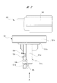
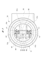
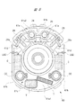
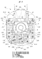
図1は本発明のモータ装置を示す平面図を、図2は図1のコネクタ部材を単体で示す平面図を、図3は図2のコネクタ部材を矢印A方向から見た図を、図4は図1のブラシホルダを単体で示す斜視図を、図5は図4のブラシホルダを矢印B方向から見た図を、図6は図4のブラシホルダを矢印C方向から見た図を、図7はブラシホルダの第1組立工程を説明する図を、図8はブラシホルダの第2組立工程を説明する図を、図9はブラシホルダの第3組立工程を説明する図を、図10はブラシホルダの第4組立工程を説明する図を、図11はブラシホルダの第5組立工程を説明する図をそれぞれ示している。 1 is a plan view showing the motor device of the present invention, FIG. 2 is a plan view showing the connector member of FIG. 1 alone, FIG. 3 is a view of the connector member of FIG. Is a perspective view showing the brush holder of FIG. 1 alone, FIG. 5 is a view of the brush holder of FIG. 4 viewed from the direction of arrow B, FIG. 6 is a view of the brush holder of FIG. 7 is a diagram illustrating a first assembly process of the brush holder, FIG. 8 is a diagram illustrating a second assembly process of the brush holder, FIG. 9 is a diagram illustrating a third assembly process of the brush holder, and FIG. FIG. 11 is a diagram illustrating a fourth assembly process of the brush holder, and FIG. 11 is a diagram illustrating a fifth assembly process of the brush holder.
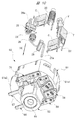
図1に示すモータ装置10は、自動車等の車両に搭載されるパワーウィンド装置の駆動源に用いられ、窓ガラスを昇降させるウィンドレギュレータを駆動させるものである。モータ装置10は、小型でありながら大きな出力が可能な減速機構付きのモータとされ、車両のドア内の狭小スペースに設置される。モータ装置10は、モータ部20とギヤ部40とを備え、これらのモータ部20およびギヤ部40は、複数の締結ネジ11により互いに連結され、ユニット化されている。
A
モータ部20は、磁性材料よりなる鋼板をプレス加工等することで、有底筒状に形成されたモータケース(ハウジング)21を備えている。モータケース21は、互いに対向する一対の平面壁部21aと、互いに対向する一対の円弧状壁部21bとを備えており、その断面形状は略小判形状に形成されている。つまり、各平面壁部21aが対向する方向(図1の奥行方向)に沿うモータケース21の厚み寸法が薄くされ、これにより、モータ部20を扁平形状として、モータ装置10をドア内の狭小スペースに配置可能としている。ここで、ギヤケース41においても、モータケース21の扁平形状に倣って扁平形状となっている。なお、図1では、図中手前側の平面壁部21aのみが示されている。
The
モータケース21の各円弧状壁部21bの内側には、断面が略円弧形状に形成された複数のマグネット22が固定されている。各マグネット22の内側には、コイル23が巻装されたアーマチュア24が、所定の隙間を介して回転自在に設けられている。そして、モータケース21の開口側(図1の左側)には、ブラシホルダ60が装着されており、当該ブラシホルダ60によって、モータケース21の開口側は塞がれている。
A plurality of
アーマチュア24の回転中心には、アーマチュア軸(回転軸)26が貫通して固定されている。アーマチュア軸26は、モータ部20およびギヤ部40の双方を横切るようにして設けられ、アーマチュア軸26の軸方向一側(図1の右側)はモータケース21内に配置され、アーマチュア軸26の軸方向他側(図1の左側)はギヤケース41内に配置されている。つまり、アーマチュア軸26は、モータケース21およびギヤケース41の内部に回転自在に収容されている。
An armature shaft (rotating shaft) 26 is fixed through the center of rotation of the
アーマチュア軸26の軸方向に沿う略中間部分で、かつアーマチュア24に近接する部位には、略円柱形状に形成されたコンミテータ(整流子)27が設けられている。コンミテータ27は、アーマチュア軸26と一体回転し、コンミテータ27には、アーマチュア24に巻装されたコイル23の端部が電気的に接続されている。
A
コンミテータ27の外周には、ブラシホルダ60に保持された複数のブラシ28が摺接され、各ブラシ28は、ばね部材29によりそれぞれコンミテータ27に向けて所定圧で押圧されている。これにより、図示しない車載コントローラから、各ブラシ28に駆動電流を供給することで、アーマチュア24に回転力(電磁力)が発生し、ひいてはアーマチュア軸26が所定の回転方向に回転される。
A plurality of
アーマチュア軸26の軸方向に沿う略中間部分で、かつコンミテータ27のアーマチュア24側とは反対側には、環状のセンサマグネット30が固定されている。センサマグネット30は、アーマチュア軸26の回転方向に沿って複数の極性を備えている。センサマグネット30は、アーマチュア軸26と一体回転され、これにより、アーマチュア軸26の回転に伴い、センサマグネット30の径方向外側に配置された回転センサ55に対する磁束線の状態が変化するようになっている。
An
アーマチュア軸26のセンサマグネット30よりも軸方向他側には、ウォーム31が設けられている。ウォーム31は略筒状に形成され、アーマチュア軸26に圧入等により固定されている。ウォーム31には、ギヤケース41内に回転自在に収容されたウォームホイール43の歯部43a(詳細図示せず)が噛み合わされている。これにより、ウォーム31はギヤケース41内でアーマチュア軸26の回転により回転され、その回転がウォームホイール43に伝達される。ここで、ウォーム31およびウォームホイール43は減速機構SDを形成している。
A worm 31 is provided on the other side of the
モータケース21の底部側(図1の右側)は段付形状に形成され、当該部位には、モータケース21の本体部分よりも小径となった小径部21cが設けられている。小径部21cには、第1軸受部材32が設けられ、この第1軸受部材32は、アーマチュア軸26の軸方向一側を、モータケース21内で回転自在に支持している。
The bottom side (the right side in FIG. 1) of the
ギヤ部40は、ギヤケース(ハウジング)41およびコネクタ部材50を備えている。ギヤケース41の開口部分(図1の手前側)は、略円盤状に形成されたギヤカバー42により閉塞されている。また、ギヤケース41は、プラスチック等の樹脂材料を射出成形することにより所定形状に形成され、モータケース21の開口側に各締結ネジ11を介して連結されている。すなわち、ギヤケース41およびモータケース21は、いずれもモータ装置10の外郭を形成している。
The
ギヤケース41内には、アーマチュア軸26に固定されたウォーム31と、外周部分にウォーム31と噛み合う歯部43aを備えたウォームホイール43とが、それぞれ回転自在に収容されている。ここで、ウォーム31は螺旋状に形成され、歯部43aはウォームホイール43の軸方向に向けて緩やかに傾斜されている。これにより、ウォーム31からウォームホイール43に対して、滑らかな動力伝達を可能としている。
In the
ウォームホイール43の回転中心には、出力部材43bが設けられ、この出力部材43bは、ウィンドレギュレータに動力伝達可能に接続されるようになっている。すなわち、アーマチュア軸26の回転は、減速機構SDにより減速されて高トルク化され、この高トルク化された回転力が、出力部材43bからウィンドレギュレータに出力されるようになっている。
An
また、ギヤケース41内のアーマチュア軸26の軸方向他側に対応する部分には、第2軸受部材44が設けられている。この第2軸受部材44は、アーマチュア軸26の軸方向他側を、ギヤケース41内で回転自在に支持している。
A
ギヤケース41の側面の部位(図1の上側)には、コネクタ部材組付孔41aが設けられている。コネクタ部材組付孔41aには、コネクタ部材50が差し込み固定されている。コネクタ部材組付孔41aの延在方向、つまりコネクタ部材50の差し込み方向は、アーマチュア軸26の延在方向および出力部材43bの延在方向の双方と直交する方向となっている。
A connector
ここで、コネクタ部材組付孔41aとコネクタ部材50との間には、シール部材としてのOリング53(図3参照)が装着され、これにより、コネクタ部材組付孔41a内への雨水等の進入が阻止される。また、コネクタ部材50は、ギヤケース41に対して、複数の固定ネジ(図示せず)によって、がたつくこと無く強固に固定されている。
Here, an O-ring 53 (see FIG. 3) as a sealing member is mounted between the connector
ギヤケース41には、3つの固定部41dが設けられている。これらの固定部41dは、出力部材43bを囲うようにしてギヤケース41の周囲にそれぞれ所定間隔(略120度間隔)で配置されている。そして、各固定部41dには、モータ装置10を車両のドア内に固定するための固定ボルト(図示せず)がそれぞれ装着される。このように、各固定部41dを、出力部材43bを囲うように所定間隔で設けることで、幅狭のドア内においてモータ装置10はバランス良く支持される。よって、モータ装置10に高負荷が掛かったとしても、モータ装置10がドア内でがたつくことを、効果的に防止することができる。
The
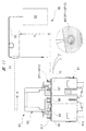
図2および図3に示すように、コネクタ部材50は、プラスチック等の樹脂材料を射出成形することで略L字形状に形成されている。コネクタ部材50は、ギヤケース41に組み付けられる組み付け部51と、外部コネクタCN(図1参照)が接続されるコネクタ接続部52とを備えている。コネクタ部材50は、ブラシホルダ60に電気的に接続され、外部コネクタCNからの駆動電流をブラシホルダ60に供給する。
As shown in FIGS. 2 and 3, the
組み付け部51は、断面形状が円形の組付本体51aを備え、この組付本体51aの周囲にはキャップ部51bが設けられている。組付本体51aは、コネクタ部材組付孔41a(図1参照)に差し込まれるようになっている。また、キャップ部51bは、ギヤケース41のコネクタ部材組付孔41aの近傍に形成された筒状部(図示せず)に装着されるようになっている。
The assembling
組付本体51aをコネクタ部材組付孔41aに差し込んだ状態で、組付本体51aとコネクタ部材組付孔41aとの間には、Oリング53が挟持される。つまり、Oリング53は弾性変形しつつ、コネクタ部材50およびギヤケース41の双方に密着されている。ここで、Oリング53には、汎用のゴム製のOリングが用いられている。
With the assembly
組付本体51aの軸方向に沿うコネクタ接続部52側とは反対側(図2の下側)には、略直方体形状に形成されたケース部51cが一体に設けられている。このケース部51cは、組付本体51aの軸方向に延在され、基板保持部51dと端子収容部51eとを備えている。そして、基板保持部51dは、センサ基板54を保持しており、端子収容部51eよりもコネクタ接続部52側とは反対側に突出されている。
On the opposite side (lower side in FIG. 2) of the assembly
センサ基板54は、略長方形形状に形成され、その長手方向に沿うコネクタ接続部52側とは反対側(図2の下側)には、回転センサ55(網掛部分)が実装されている。回転センサ55は、センサマグネット30(図1参照)の径方向外側に配置され、センサマグネット30の磁束線の向きやその変化を捉える磁気センサとなっている。これにより、回転センサ55は、アーマチュア軸26(図1参照)の回転状態、つまりアーマチュア軸26の回転方向や回転速度を検出する。具体的には、回転センサ55は、センサ素子としての磁気抵抗素子(MR素子)備え、さらには巨大磁気抵抗効果現象(Giant Magneto Resistance Effect)を応用したGMRセンサとなっている。
The
センサ基板54には、4本のセンサ用導電部材56(網掛部分)の長手方向一側がはんだ付け等の接続手段により電気的に接続されている。一方、これらのセンサ用導電部材56の長手方向他側は、コネクタ接続部52の内部に露出されている(詳細図示せず)。これにより、回転センサ55の検出信号は、各センサ用導電部材56および外部コネクタCNを介して、車載コントローラに送出される。
One side in the longitudinal direction of the four
図3に示すように、コネクタ部材50内には、各センサ用導電部材56に加えて、一対のコネクタ側駆動用導電部材57(網掛部分)が設けられている。そして、端子収容部51e内には、各コネクタ側駆動用導電部材57の長手方向一端側にそれぞれ設けられたコネクタ側メス型端子(コネクタ側接続端子)FTが収容されている。つまり、これらのコネクタ側メス型端子FTは、組付本体51aの差し込み方向に沿う先端側に設けられている。
As shown in FIG. 3, a pair of connector-side driving conductive members 57 (shaded portions) are provided in the
これに対し、各コネクタ側駆動用導電部材57の長手方向他端側には、コネクタ側オス型端子(図示せず)がそれぞれ形成され、各コネクタ側オス型端子は、コネクタ接続部52の内部に露出されている。これにより、各コネクタ側駆動用導電部材57には、外部コネクタCNを介して、車載コントローラからの駆動電流が供給される。
On the other hand, a connector-side male terminal (not shown) is formed on the other end in the longitudinal direction of each connector-side drive
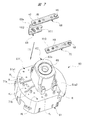
図4ないし図11に示すように、ブラシホルダ60は、モータケース21およびギヤケース41内に設けられ、プラスチック等の樹脂材料を射出成形することで所定形状に形成されている。ブラシホルダ60は、ホルダ本体61と軸受保持筒(軸受装着部)62とを備えている。ここで、ブラシホルダ60には、コネクタ部材50が接続される。これにより、アーマチュア軸26を回転させるための駆動電流が、外部コネクタCNからコネクタ部材50を介して、ブラシホルダ60に供給される。なお、図4ないし図11では、構成部品を明瞭にするために、ブラシホルダ60に装着される部品(電子部品)に網掛けを施している。
As shown in FIGS. 4 to 11, the
ホルダ本体61は、第1底壁部61a1および第2底壁部61a2を備えている。これらの第1,第2底壁部61a1,61a2は、それぞれ平板状に形成され、ブラシホルダ60の軸方向に対する位置が互いに異なっている。つまり、第1,第2底壁部61a1,61a2は、互いに階段状に段違いになっている。そして、ブラシホルダ60の軸方向から見た第1,第2底壁部61a1,61a2の投影形状は、略小判形状とされる。これにより、ブラシホルダ60は、モータケース21内の開口側(図1の左側)に装着可能となっている。なお、第1底壁部61a1の面積S1の方が、第2底壁部61a2の面積S2よりも大きく(S1>S2)、第1底壁部61a1は、ホルダ本体61の底壁の略2/3の部分を占めている。
The holder
第1,第2底壁部61a1,61a2の周囲には、側壁部(側壁)61bが設けられている。側壁部61bは、第1,第2底壁部61a1,61a2の周囲から、ブラシホルダ60(アーマチュア軸26)の軸方向(図4の下側)に延在されている。ここで、第1,第2底壁部61a1,61a2は、本発明における部品取付壁を構成しており、これらの第1,第2底壁部61a1,61a2は、ブラシホルダ60(アーマチュア軸26)の軸方向と交差する方向に延在されている。
A side wall portion (side wall) 61b is provided around the first and second bottom wall portions 61a1 and 61a2. The
第2底壁部61a2の周囲に設けられた側壁部61bは、第1底壁部61a1の周囲に設けられた側壁部61bよりも、ブラシホルダ60の軸方向に沿う長さが短くなっている。したがって、第1,第2底壁部61a1,61a2は、互いに段違いとされ、第1底壁部61a1の方が、第2底壁部61a2よりも、第3軸受部材(軸受)65の近くに配置されている。
The
また、側壁部61bには、複数の圧入突起61b1が一体に設けられている。これらの圧入突起61b1は、モータケース21内に圧入される。これにより、ブラシホルダ60は、アーマチュア軸26の径方向にがたつくこと無くモータケース21に固定されて、各ブラシ28のコンミテータ27(図1参照)への摺接状態を安定化させている。
Further, a plurality of press-fit projections 61b1 are integrally provided on the
第1底壁部61a1には、軸受保持筒62が一体に設けられている。この軸受保持筒62は、側壁部61bの延在方向とは逆方向(図4の上側)に延在されている。そして、軸受保持筒62の軸方向長さは、第1底壁部61a1に対応して設けられた側壁部61bの突出長さと略同じ長さとなっている。
The
軸受保持筒62は、一対の円弧状壁62aと一対の平面壁62bとを備えている。また、軸受保持筒62の軸方向に沿う第1底壁部61a1側とは反対側の先端部分には、軸受収容部62cが形成されている。そして、軸受収容部62cには、アーマチュア軸26(図1参照)の軸方向中間部分を回転自在に支持する第3軸受部材65が装着されている。
The
軸受保持筒62の内側には、センサマグネット30(図1参照)が配置され、コネクタ部材組付孔41a(図1参照)側に面する平面壁62bには、コネクタ側メス型端子FT(図3参照)が接続される方向に沿う各ブラシ側オス型端子MTの背面部BC(図8参照)が当接されている。このように、軸受保持筒62は、センサマグネット30の周囲を覆い、かつ各ブラシ側オス型端子MTの背面部BCを支持している。これにより、ブラシ側オス型端子MTに対してコネクタ側メス型端子FT(図3参照)を接続する際に、ブラシ側オス型端子MTとセンサマグネット30との接触が防止され、かつブラシ側オス型端子MTの変形が防止される。
The sensor magnet 30 (see FIG. 1) is disposed inside the
さらに、軸受保持筒62の平面壁62bは、センサマグネット30と回転センサ55(図2および図3参照)との間に設けられる仕切壁としても機能する。これにより、センサマグネット30側にある各ブラシ28の摩耗粉が、回転センサ55やセンサ基板54に付着しないようにしている。よって、回転センサ55の検出性能の低下が長期に亘り抑制される。
Further, the
図5に示すように、アーマチュア軸26の軸方向に沿う第1,第2底壁部61a1,61a2の一側、つまりブラシホルダ60の軸方向に沿う第1,第2底壁部61a1,61a2の側壁部61bが設けられた側(図5の手前側)には、第1壁面61cが形成されている。そして、第1底壁部61a1に対応した第1壁面61cには、バリスタVと、一対のキャパシタCと、一対のチョークコイルCCと、PTC(Positive Temperature Coefficient)サーミスタTとが装着されている。
As shown in FIG. 5, one side of the first and second bottom wall portions 61a1 and 61a2 along the axial direction of the
また、第2底壁部61a2に対応した第1壁面61cには、一対のブラシケース61dと、一対の支持ピン61eとが設けられている。そして、各ブラシケース61dには、ブラシ28が、ブラシホルダ60の径方向に移動自在にそれぞれ収容されている。また、各支持ピン61eには、ばね部材29が装着されている。
The
ここで、バリスタV,キャパシタC,チョークコイルCC,PTCサーミスタTは、それぞれ本発明における他の部品(電子部品)を構成している。そして、バリスタV,キャパシタCおよびチョークコイルCCは、各ブラシ28のコンミテータ27に対する摺接により発生する電気ノイズを吸収し、当該電気ノイズがモータ装置10の外部に放散されるのを防止する。つまり、バリスタV,キャパシタCおよびチョークコイルCCは、雑音防止素子として機能する。また、PTCサーミスタTは、モータ装置10の過熱時に流れる駆動電流を小さくして、モータ装置10がそれ以上過熱されるのを防止する。つまり、PTCサーミスタTは、モータ装置10を熱から保護する熱保護素子として機能する。
Here, the varistor V, the capacitor C, the choke coil CC, and the PTC thermistor T each constitute another component (electronic component) in the present invention. The varistor V, the capacitor C, and the choke coil CC absorb the electric noise generated by the sliding contact of each
このように、モータ装置10を構成する一対のブラシ28と、バリスタVと、一対のキャパシタCと、一対のチョークコイルCCと、PTCサーミスタTとは、それぞれ第1壁面61c側のみに集約して配置されている。より具体的には、図5に示すように、ブラシホルダ60の軸方向に沿う第1壁面61cの投影範囲内に、上記複数の部品が適度に分散された状態で設けられている。また、これらの部品は、ブラシホルダ60の軸方向に重なっていない。したがって、上記複数の部品の第1壁面61cへの配置作業を、自動組立装置(図示せず)を用いて、より容易にかつ確実に行うことが可能となる。
In this manner, the pair of
一対のブラシ28と、バリスタVと、一対のキャパシタCと、一対のチョークコイルCCと、PTCサーミスタTとを、それぞれ第1壁面61cに配置した状態で、これらの部品は、図11に示すように、ブラシホルダ60(アーマチュア軸26)の軸方向と交差する方向から、側壁部61bによって覆われている。つまり、図11に示すように、ブラシホルダ60を真横から見ると、上記複数の部品は側壁部61bにより隠されている。これにより、第1壁面61cに配置された上記複数の部品は、第1,第2底壁部61a1,61a2と側壁部61bとで囲まれた内側に収容されて、ブラシホルダ60の搬送時等において、上記複数の部品の損傷等を確実に防止することができる。
With a pair of
そして、一対のブラシ28にはそれぞれピグテール(導線)28aの基端側が接続され、各ピグテール28aの先端側は、図6に示すように、第1底壁部61a1の第2壁面61f側に引き出されている。また、バリスタV,キャパシタC,チョークコイルCCおよびPTCサーミスタTには、それぞれ一対の接続脚LG1,LG2,LG3,LG4が設けられている。そして、これらの接続脚LG1,LG2,LG3,LG4の先端側についても、図6に示すように、第1底壁部61a1の第2壁面61f側に引き出されている。
The pair of
ただし、キャパシタCの一方の接続脚LG2については、その先端側は第2壁面61f側に向けられているが、側壁部61b(図5参照)の外側に引き出されている。これにより、キャパシタCの一方の接続脚LG2は、ブラシホルダ60をモータケース21に装着した状態で、モータケース21に電気的に接続(アース)されるようになっている。
However, one end of the connection leg LG2 of the capacitor C is directed toward the
図6に示すように、アーマチュア軸26の軸方向に沿う第1底壁部61a1の他側、つまりブラシホルダ60の軸方向に沿う第1底壁部61a1の側壁部61bが設けられた側とは反対側(図6の手前側)には、第2壁面61fが形成されている。そして、第2壁面61f上には、黄銅等の導電体をプレス成形等してなる5つの導電部材66,67,68,69,70が装着されている。これらの導電部材66,67,68,69,70は、第1壁面61c側から第2壁面61f側に向けて延びる(引き出された)ピグテール28aの先端側および各接続脚LG1,LG2,LG3,LG4を、互いに電気的に接続する機能を備えている。これにより、ブラシホルダ60に、モータ装置10を駆動するための電気回路が形成される。
As shown in FIG. 6, the other side of the first bottom wall portion 61a1 along the axial direction of the
5つある導電部材のうちの一対の導電部材66,67は、コネクタ部材50に設けた一対のコネクタ側駆動用導電部材57(図3参照)に電気的に接続される、ブラシ側駆動用導電部材(給電用導電部材)を形成している。すなわち、外部コネクタCNからの駆動電流は、各コネクタ側駆動用導電部材57を介して、各導電部材66,67に供給される。
A pair of
図8に示すように、各導電部材66,67は、それぞれ板材を屈曲することで略同様のクランク形状に形成され、第2壁面61fに対して面接触される装着部66a,67aを備えている。ここで、各装着部66a,67aには、第2壁面61f側から第1壁面61c側に向けて突出された部分を備えていない。つまり、各装着部66a,67aは、第2壁面61fに対して平面のみで接触している。また、各導電部材66,67の長手方向に沿う装着部66a,67aがある側とは反対側には、ブラシ側オス型端子MTがそれぞれ設けられている。
As shown in FIG. 8, each of the
各導電部材66,67の長手方向に沿う装着部66a,67aとブラシ側オス型端子MTとの間には、中間部66b,67bがそれぞれ設けられている。ここで、中間部66b,67bの板厚方向は、ブラシホルダ60の径方向に向けられている。すなわち、中間部66b,67bの板厚方向と交差する中間部66b,67bの幅方向は、ブラシホルダ60(アーマチュア軸26)の軸方向に向けられている。これにより、ブラシホルダ60が径方向外側に大型化するのを抑えている。なお、中間部66b,67bには、自動組立装置のチャック(図示せず)によって把持される把持片66c,67cが一体に設けられている。
また、各導電部材66,67の長手方向に沿う中間部66b,67bとブラシ側オス型端子MTとの間には、軸受保持筒62の平面壁62b(図6参照)に当接される背面部BCがそれぞれ設けられている。これにより、コネクタ部材50の差し込み荷重F(図6参照)が、装着部66a,67aに伝達されるのを防止して、装着部66a,67aに設けられる接続部CP1〜CP4に無理な力が掛からないようにしている。
In addition, between the
そして、図6に示すように、各導電部材66,67の長手方向一側に設けられる装着部66a,67a(接続部CP1〜CP4)は、アーマチュア軸26の軸方向と交差する方向に沿う軸受保持筒62を中心とした一方側、つまり第1底壁部61a1側(図6の下側)に配置されている。これに対し、各導電部材66,67の長手方向他側に設けられるブラシ側オス型端子(接続端子)MTは、アーマチュア軸26の軸方向と交差する方向に沿う軸受保持筒62を中心とした他方側、つまり第2底壁部61a2側(図6の上側)に配置されている。
As shown in FIG. 6, mounting
導電部材66の装着部66aには、2つの接続部CP1,CP2が配置されている。また、導電部材67の装着部67aには、2つの接続部CP3,CP4が配置されている。なお、図6に示すように、それぞれの装着部66a,67aに対応する樹脂突起Rは、ブラシホルダ60に一体に設けられ、当該樹脂突起Rを、発熱治具(図示せず)を用いて熱かしめする(押し潰す)ことで、各導電部材66,67は第2壁面61fに固定される。
Two connecting portions CP1 and CP2 are arranged on the mounting
装着部66aに配置された接続部CP1は、PTCサーミスタTの一方の接続脚LG4と、導電部材66に設けられた貫通孔H1(図8参照)との間に設けられ、それぞれが互いに電気的に接続された部分となっている。具体的には、接続部CP1は、一方の接続脚LG4を導電部材66の貫通孔H1に貫通させた状態で、双方をレーザー溶接(図11参照)により溶着することで形成される。ただし、図4および図6に示す接続部CP1〜CP12の状態は、レーザー溶接により溶着する前の状態を示している。そして、接続部CP1〜CP12のレーザー溶接による溶着後は、図11の破線円に示すような接続部WDとなる。
The connection portion CP1 disposed on the mounting
また、装着部66aに配置された接続部CP2は、バリスタVの一方の接続脚LG1と、導電部材66に設けられた貫通孔H2(図8参照)との間に設けられ、それぞれが互いに、接続部CP1と同様にレーザー溶接により電気的に接続された部分となっている。
The connection portion CP2 disposed on the mounting
装着部67aに配置された接続部CP3は、一方のチョークコイルCCの一方の接続脚LG3と、導電部材67に設けられた貫通孔H3(図8参照)との間に設けられ、それぞれが互いに、接続部CP1と同様にレーザー溶接により電気的に接続された部分となっている。また、装着部67aに配置された接続部CP4は、バリスタVの他方の接続脚LG1と、導電部材67に設けられた貫通孔H4(図8参照)との間に設けられ、それぞれが互いに、接続部CP1と同様にレーザー溶接により電気的に接続された部分となっている。
The connection portion CP3 disposed on the mounting
図6および図7に示すように、5つある導電部材のうちの一対の導電部材68,70は、軸受保持筒62を中心に、各導電部材66,67よりも外側に配置されている。具体的には、各導電部材68,70は、それぞれ側壁部61b(図5参照)寄りに配置されている。各導電部材68,70は、板材をプレス成形することで、それぞれ略長方形形状の平板状に形成され、各導電部材68,70は、いずれも第1底壁部61a1側の第2壁面61fに対して面接触されている。ここで、各導電部材68,70についても、第2壁面61f側から第1壁面61c側に向けて突出された部分を備えていない。つまり、各導電部材68,70は、第2壁面61fに対して平面のみで接触している。
As shown in FIGS. 6 and 7, a pair of
導電部材68には、3つの接続部CP5,CP6,CP7が配置されている。また、導電部材70には、3つの接続部CP8,CP9,CP10が配置されている。なお、図6に示すように、各導電部材68,70に対応する樹脂突起Rは、ブラシホルダ60に一体に設けられ、当該樹脂突起Rを、発熱治具を用いて熱かしめすることで、各導電部材68,70は第2壁面61fに固定される。
The
導電部材68に配置された接続部CP5は、一方のブラシ28のピグテール28aの先端側と、導電部材68に設けられた貫通孔H5(図7参照)との間に設けられ、それぞれが互いに、接続部CP1と同様にレーザー溶接により電気的に接続された部分となっている。また、導電部材68に配置された接続部CP6は、一方のキャパシタCの他方の接続脚LG2と、導電部材68に設けられた貫通孔H6(図7参照)との間に設けられ、それぞれが互いに、接続部CP1と同様にレーザー溶接により電気的に接続された部分となっている。さらに、導電部材68に配置された接続部CP7は、他方のチョークコイルCCの一方の接続脚LG3と、導電部材68に設けられた貫通孔H7(図7参照)との間に設けられ、それぞれが互いに、接続部CP1と同様にレーザー溶接により電気的に接続された部分となっている。
The connecting portion CP5 disposed on the
導電部材70に配置された接続部CP8は、他方のブラシ28のピグテール28aの先端側と、導電部材70に設けられた貫通孔H8(図7参照)との間に設けられ、それぞれが互いに、接続部CP1と同様にレーザー溶接により電気的に接続された部分となっている。また、導電部材70に配置された接続部CP9は、他方のキャパシタCの他方の接続脚LG2と、導電部材70に設けられた貫通孔H9(図7参照)との間に設けられ、それぞれが互いに、接続部CP1と同様にレーザー溶接により電気的に接続された部分となっている。さらに、導電部材70に配置された接続部CP10は、一方のチョークコイルCCの他方の接続脚LG3と、導電部材70に設けられた貫通孔H10(図7参照)との間に設けられ、それぞれが互いに、接続部CP1と同様にレーザー溶接により電気的に接続された部分となっている。
The connecting portion CP8 disposed on the
図6および図7に示すように、5つある導電部材のうちの1つの導電部材69は、導電部材66と導電部材68との間に配置されている。具体的には、導電部材69は、板材をプレス成形することで、導電部材68,70よりも長さが短い略長方形形状の平板状に形成され、導電部材69は、第1底壁部61a1側の第2壁面61fに対して面接触されている。ここで、導電部材69についても、第2壁面61f側から第1壁面61c側に向けて突出された部分を備えていない。つまり、導電部材69は、第2壁面61fに対して平面のみで接触している。
As shown in FIGS. 6 and 7, one of the five
導電部材69には、2つの接続部CP11,CP12が配置されている。なお、図6に示すように、導電部材69に対応する樹脂突起Rは、ブラシホルダ60に一体に設けられ、当該樹脂突起Rを、発熱治具を用いて熱かしめすることで、導電部材69は第2壁面61fに固定される。
Two connecting portions CP11 and CP12 are arranged on the
導電部材69に配置された接続部CP11は、他方のチョークコイルCCの他方の接続脚LG3と、導電部材69に設けられた貫通孔H11(図7参照)との間に設けられ、それぞれが互いに、接続部CP1と同様にレーザー溶接により電気的に接続された部分となっている。また、導電部材69に配置された接続部CP12は、PTCサーミスタTの他方の接続脚LG4と、導電部材69に設けられた貫通孔H12(図7参照)との間に設けられ、それぞれが互いに、接続部CP1と同様にレーザー溶接により電気的に接続された部分となっている。
The connection portion CP11 disposed on the
また、導電部材69には、自動組立装置のチャック(図示せず)によって把持される把持片69aが一体に設けられている。ここで、一対の導電部材68,70には、把持片が設けられていない。これは、各導電部材68,70は、導電部材69に比して大きく、自動組立装置のチャックにより把持し得るスペースを備えているからである。
The
また、図7に示すように、第1底壁部61a1側の第1壁面61cと第2壁面61fとの間には、両者間を連通する複数の連通孔HLが設けられている。これらの連通孔HLには、バリスタV,キャパシタC,チョークコイルCCおよびPTCサーミスタTの接続脚LG1,LG2,LG3,LG4が、それぞれ挿通される。さらに、第1底壁部61a1側の第2壁面61fには、一対の仕切壁71a,71bが一体に設けられている。これにより、隣り合う導電部材間の短絡を確実に防止している。また、各仕切壁71a,71bを設けることで、隣り合う導電部材の間隔を詰めることができ、ブラシホルダ60の小型化にも有利である。
As shown in FIG. 7, between the
次に、以上のように形成したブラシホルダ60の組み立て手順について、図面を用いて詳細に説明する。
Next, the procedure for assembling the
[第1組立工程]
図7に示すように、まず、別の製造工程で製造された3つの導電部材68,69,70を準備するとともに、軸受収容部62cに第3軸受部材65を組み付けたブラシホルダ60を準備する。ただし、第3軸受部材65は、第5組立工程の後(最後)にブラシホルダ60に組み付けても良い。
[First assembly process]
As shown in FIG. 7, first, three
そして、ブラシホルダ60を自動組立装置の基台(図示せず)の上にセットする。ここで、図7に示すように、軸受保持筒62が上方を向くように、ブラシホルダ60を基台にセットする。ここで、当該基台には、ブラシホルダ60に設けられた複数の連通孔HLに差し込まれる複数の位置決めピン(図示せず)が設けられている。これにより、ブラシホルダ60は、基台上にがたつくこと無く正確に位置決めされる。
Then, the
次いで、図7の矢印(1)に示すように、各導電部材68,69,70をブラシホルダ60に臨ませて、各導電部材68,69,70を、第1底壁部61a1側の第2壁面61f上にそれぞれ載せる。ここで、各導電部材68,69,70の第2壁面61f上への載置作業は、作業ロボット(図示せず)によって行われる。ここで、各導電部材68,69,70を、それぞれ同じ高さ位置にある第2壁面61f上に載せるだけなので、作業ロボットの簡単な制御により容易かつ正確に載置作業を行うことができる。
Next, as shown by an arrow (1) in FIG. 7, each
これにより、各導電部材68,69,70が、位置決めピン(図示せず)やブラシホルダ60の樹脂突起Rによって、図8に示すように正確に位置決めされる。これにより、第1組立工程が完了する。
As a result, the
[第2組立工程]
次に、図8に示すように、別の製造工程で製造された2つの導電部材(給電用導電部材)66,67を準備する。そして、図8の矢印(2)に示すように、各導電部材66,67をブラシホルダ60に臨ませて、各導電部材66,67を、第1底壁部61a1側の第2壁面61f上に載せる。ここで、各導電部材66,67の第2壁面61f上への載置作業についても、第1組立工程と同じ作業ロボットによって行われる。
[Second assembly process]
Next, as shown in FIG. 8, two conductive members (power supply conductive members) 66 and 67 manufactured in different manufacturing steps are prepared. Then, as shown by an arrow (2) in FIG. 8, the
このように、各導電部材66,67においても、各導電部材68,69,70と同じ高さ位置の第2壁面61f上に載せるだけなので、作業ロボットの簡単な制御により容易かつ正確に載置作業を行うことができる。これにより、各導電部材66,67が位置決めピン(図示せず)やブラシホルダ60の樹脂突起Rによって、図9に示すように正確に位置決めされる。これにより、第2組立工程が完了する。
As described above, since each of the
[第3組立工程]
その後、図9に示すように、第1,第2組立工程と同じ基台にブラシホルダ60をセットした状態で、別の作業ロボットにより熱かしめ作業を行う。具体的には、作業ロボットを制御することで、発熱治具(図示せず)を図9の矢印(3)に示すように、樹脂突起Rの先端部分に臨ませて、当該樹脂突起Rの先端部分を加熱して変形させる。なお、樹脂突起Rの数は、本実施の形態では、合計7箇所となっている。
[Third assembly process]
After that, as shown in FIG. 9, while the
これにより、各導電部材66,67,68,69,70が、ブラシホルダ60の第1底壁部61a1側の第2壁面61f上(同一平面上)に、がたつくこと無く強固に固定される。ここで、各導電部材66,67,68,69,70の第2壁面61f上への固定作業においても、作業ロボットの発熱治具の位置を、第2壁面61f上の同じ高さ位置で制御すれば良いので、作業ロボットの簡単な制御により容易かつ正確に固定作業を行うことができる。これにより、第3組立工程が完了する。
Thereby, the
[第4組立工程]
次いで、図10に示すように、第1工程ないし第3工程に用いた基台から、第4工程用の基台(図示せず)にブラシホルダ60を移動させる。このとき、第4工程の基台には、軸受保持筒62が下方を向くように、ブラシホルダ60をセットする。その後、図10の矢印(4)に示すように、作業ロボットを制御することで、第1底壁部61a1および第2底壁部61a2の第1壁面61c(図5参照)に、一対のブラシ28,一対のばね部材29,バリスタV,一対のキャパシタC,一対のチョークコイルCC,PTCサーミスタTを、それぞれ装着する。
[Fourth assembly process]
Next, as shown in FIG. 10, the
これにより、図5に示すように、上記複数の部品が、第1壁面61c上の所定箇所に正確に装着される。これにより、第4組立工程が完了する。
Thereby, as shown in FIG. 5, the plurality of components are accurately mounted at predetermined locations on the
[第5組立工程]
その後、図11に示すように、第4工程に用いた基台から、第5工程用の基台(図示せず)にブラシホルダ60を移動させる。このとき、第5工程の基台には、軸受保持筒62が上方を向くように、ブラシホルダ60をセットする。その後、作業ロボットを制御して、レーザー溶接機80の加工ヘッド(トーチ)81を、図11の破線矢印Mに示すように移動させて、合計12箇所の接続部CP1〜CP12を形成していく。
[Fifth assembly process]
Thereafter, as shown in FIG. 11, the
ここで、レーザー溶接機80は、YAG(イットリウム,アルミニウム,ガーネット)レーザーを発生する発振器82を備え、当該発振器82と加工ヘッド81との間には、柔軟性を有する光ファイバー83が設けられている。これにより、高エネルギーのレーザー光線Lが、加工ヘッド81がからブラシホルダ60の第2壁面61f上に照射されて、接続部CP1〜CP12を、それぞれ同じ条件で素早く形成することができる。
Here, the
なお、1箇所の接続部の形成に掛かるレーザー光線Lの照射時間は、レーザー光線Lのエネルギー量にもよるが、概ね0.1S〜0.2Sに設定されている。したがって、はんだ付け等をする場合に比して、大幅に時間短縮ができる。また、図11に示すように、接続部CP1〜CP12が、第1底壁部61a1の第2壁面61f側で同一平面上のみに設けられている。そのため、作業ロボットは、加工ヘッド81の高さ制御(図11の上下方向への移動)をしなくて済む。
The irradiation time of the laser beam L required to form one connection portion is generally set to 0.1S to 0.2S, though it depends on the energy amount of the laser beam L. Therefore, the time can be greatly reduced as compared with the case of performing soldering or the like. As shown in FIG. 11, the connection portions CP1 to CP12 are provided only on the same plane on the
したがって、加工ヘッド81と接続部CP1〜CP12との間の距離Sを一定としたままで、かつレーザー光線Lのエネルギー量を変えずに接続作業を行える。よって、作業ロボットの簡単な制御により容易かつ正確に接続作業を行うことができ、かつ破線円に示すように、接続部CP1〜CP12の状態を、ばらつきが無く見栄えが綺麗な接続部WDにできる。これにより、第5組立工程が完了し、ブラシホルダ60が完成する。
Therefore, the connection operation can be performed while the distance S between the processing
以上詳述したように、本実施の形態に係るモータ装置10によれば、第1,第2底壁部61a1,61a2の第1壁面61cに、ブラシ28,バリスタV,キャパシタC,チョークコイルCC,PTCサーミスタTが装着され、第1底壁部61a1の第2壁面61fに、ブラシ28,バリスタV,キャパシタC,チョークコイルCC,PTCサーミスタTを互いに電気的に接続する導電部材66〜70が装着され、ブラシ28,バリスタV,キャパシタC,チョークコイルCC,PTCサーミスタTと導電部材66〜70との間にそれぞれを互いに電気的に接続する接続部CP1〜CP12が設けられ、これらの接続部CP1〜CP12が第2壁面61f側で同一平面上のみに設けられている。
As described in detail above, according to the
これにより、第1壁面61c側にブラシ28,バリスタV,キャパシタC,チョークコイルCC,PTCサーミスタTを集約させ、かつ第2壁面61f側に導電部材66〜70および接続部CP1〜CP12を集約させることができる。したがって、ブラシホルダ60に組み付けられる部品等の配置構造を簡素化することができ、自動組立装置を用いてブラシホルダ60を組み立てられるようになる。また、電気的に接続すべき接続部CP1〜CP12が、第2壁面61f側で同一平面上のみに設けられているので、接続部CP1〜CP12の接続作業も自動組立装置で行えるようになる。よって、ブラシホルダ60の製造コストを低減させ、かつ歩留まりを良くすることが可能となる。
Thereby, the
また、本実施の形態に係るモータ装置10によれば、導電部材66〜70は、第2壁面61f側から第1壁面61c側に向けて突出された部分を備えていないので、導電部材66〜70のブラシホルダ60への載置作業を複雑化させずに済む。よって、この点からも自動組立装置での組み立てに有利な構造となっている。
Further, according to
さらに、本実施の形態に係るモータ装置10によれば、導電部材66,67の中間部66b,67bにおいて、当該中間部66b,67bの板厚方向と交差する幅方向を、アーマチュア軸26の軸方向に向けている。これにより、ブラシホルダ60の体格を従前のものと同じ体格としつつ、第2壁面61f側に導電部材66〜70および接続部CP1〜CP12を集約可能としている。
Furthermore, according to
また、本実施の形態に係るモータ装置10によれば、ブラシ側オス型端子MTのコネクタ側メス型端子FTが接続される方向に沿う背面部BCが、軸受保持筒62の平面壁62bに当接されている。これにより、装着部66a,67aに設けられる接続部CP1〜CP4に無理な力が掛からないようにして、通電不良等の発生を確実に防止して、歩留まりを向上させることができる。
Further, according to
さらに、本実施の形態に係るモータ装置10によれば、ブラシ28,バリスタV,キャパシタC,チョークコイルCC,PTCサーミスタTが、アーマチュア軸26の軸方向と交差する方向から側壁部61bにより覆われているので、第1壁面61cに配置された上記複数の部品を、第1,第2底壁部61a1,61a2と側壁部61bとで囲まれた内側に収容できる。よって、ブラシホルダ60の搬送時等に、上記複数の部品が損傷等するのを確実に防止できる。
Further, according to
本発明は上記実施の形態に限定されるものではなく、その要旨を逸脱しない範囲で種々変更可能であることは言うまでもない。例えば、上記実施の形態においては、モータ装置10を、車両に搭載されるパワーウィンド装置の駆動源として用いたものを示したが、本発明はこれに限らず、サンルーフ装置等の他の駆動源としても用いることができる。
The present invention is not limited to the above embodiment, and it goes without saying that various changes can be made without departing from the scope of the invention. For example, in the above embodiment, the
その他、上記実施の形態における各構成要素の材質,形状,寸法,数,設置箇所等は、本発明を達成できるものであれば任意であり、上記実施の形態に限定されない。 In addition, the materials, shapes, dimensions, numbers, installation locations, and the like of the components in the above embodiment are arbitrary as long as the present invention can be achieved, and are not limited to the above embodiment.
10 モータ装置
11 締結ネジ
20 モータ部
21 モータケース(ハウジング)
21a 平面壁部
21b 円弧状壁部
21c 小径部
22 マグネット
23 コイル
24 アーマチュア
26 アーマチュア軸(回転軸)
27 コンミテータ(整流子)
28 ブラシ
28a ピグテール
29 ばね部材
30 センサマグネット
31 ウォーム
32 第1軸受部材
40 ギヤ部
41 ギヤケース(ハウジング)
41a コネクタ部材組付孔
41d 固定部
42 ギヤカバー
43 ウォームホイール
43a 歯部
43b 出力部材
44 第2軸受部材
50 コネクタ部材
51 組み付け部
51a 組付本体
51b キャップ部
51c ケース部
51d 基板保持部
51e 端子収容部
52 コネクタ接続部
53 Oリング
54 センサ基板
55 回転センサ
56 センサ用導電部材
57 コネクタ側駆動用導電部材
60 ブラシホルダ
61 ホルダ本体
61a1 第1底壁部(部品取付壁)
61a2 第2底壁部(部品取付壁)
61b 側壁部(側壁)
61b1 圧入突起
61c 第1壁面
61d ブラシケース
61e 支持ピン
61f 第2壁面
62 軸受保持筒(軸受装着部)
62a 円弧状壁
62b 平面壁
62c 軸受収容部
65 第3軸受部材(軸受)
66,67 導電部材(給電用導電部材)
68〜70 導電部材
66a,67a 装着部
66b,67b 中間部
66c,67c,69a 把持片
71a,71b 仕切壁
80 レーザー溶接機
81 加工ヘッド
82 発振器
83 光ファイバー
BC 背面部
C キャパシタ(他の部品)
CC チョークコイル(他の部品)
CN 外部コネクタ
CP1〜CP12 接続部
FT コネクタ側メス型端子(コネクタ側接続端子)
H1〜H12 貫通孔
HL 連通孔
L レーザー光線
LG1〜LG4 接続脚
MT ブラシ側オス型端子(接続端子)
R 樹脂突起
SD 減速機構
T PTCサーミスタ(他の部品)
V バリスタ(他の部品)
WD 接続部(溶着後)
DESCRIPTION OF
21a
27 commutator
28
41a Connector
61a2 Second bottom wall (part mounting wall)
61b Side wall (side wall)
61b1 Press-
62a arc-shaped
66, 67 conductive member (power supply conductive member)
68-70
CC choke coil (other parts)
CN external connector CP1-CP12 connection part FT female terminal on connector side (connector terminal on connector side)
H1 to H12 Through hole HL communication hole L Laser beam LG1 to LG4 Connection leg MT Male terminal on brush side (connection terminal)
R Resin protrusion SD Reduction mechanism T PTC thermistor (other parts)
V Varistor (other parts)
WD connection (after welding)
Claims (5)
前記回転軸に設けられた整流子と、
前記整流子に摺接されるブラシと、
前記ブラシを保持するブラシホルダと、
前記ブラシホルダに設けられ、前記回転軸の軸方向と交差する方向に延在された部品取付壁と、
前記回転軸の軸方向に沿う前記部品取付壁の一側に設けられ、前記ブラシおよび他の部品が装着される第1壁面と、
前記回転軸の軸方向に沿う前記部品取付壁の他側に設けられ、前記ブラシおよび前記他の部品を互いに電気的に接続する導電部材が装着される第2壁面と、
前記ブラシと前記導電部材との間および前記他の部品と前記導電部材との間に設けられ、それぞれを互いに電気的に接続する接続部と、
を有し、
前記接続部が、前記第2壁面側で同一平面上のみに設けられ、
前記第2壁面に複数の前記導電部材が装着され、前記複数の導電部材のうちの少なくとも2つが、板材を屈曲してなる給電用導電部材とされ、
前記部品取付壁に、前記回転軸を回転自在に支持する軸受が装着される軸受装着部が設けられ、
前記給電用導電部材の前記回転軸の軸方向と交差する方向に沿う前記軸受装着部を中心とした一方側に、前記接続部が配置され、
前記給電用導電部材の前記回転軸の軸方向と交差する方向に沿う前記軸受装着部を中心とした他方側に、接続端子が配置され、
前記給電用導電部材の前記接続部と前記接続端子との間の中間部において、当該中間部の板厚方向と交差する幅方向が、前記回転軸の軸方向に向けられている、
モータ装置。 A motor device having a rotating shaft that is rotated by supplying a driving current,
A commutator provided on the rotating shaft;
A brush that slides on the commutator;
A brush holder for holding the brush,
A component mounting wall provided on the brush holder and extending in a direction intersecting an axial direction of the rotation shaft;
A first wall surface provided on one side of the component mounting wall along the axial direction of the rotating shaft, on which the brush and other components are mounted;
A second wall surface provided on the other side of the component mounting wall along the axial direction of the rotating shaft, on which a conductive member that electrically connects the brush and the other component to each other is mounted;
A connection portion that is provided between the brush and the conductive member and between the other component and the conductive member, and electrically connects each other,
Has,
The connection portion is provided only on the same plane on the second wall surface side ,
A plurality of the conductive members are mounted on the second wall surface, and at least two of the plurality of the conductive members are power supply conductive members formed by bending a plate material,
The component mounting wall is provided with a bearing mounting portion on which a bearing that rotatably supports the rotating shaft is mounted,
On one side around the bearing mounting portion along the direction intersecting the axial direction of the rotating shaft of the power supply conductive member, the connection portion is disposed,
A connection terminal is disposed on the other side of the power supply conductive member around the bearing mounting portion along a direction intersecting the axial direction of the rotating shaft,
In an intermediate portion between the connection portion and the connection terminal of the power supply conductive member, a width direction intersecting a thickness direction of the intermediate portion is directed in an axial direction of the rotation shaft .
Motor device.
前記ブラシおよび前記他の部品に、前記第1壁面側から前記第2壁面側に向けて延びる接続脚が設けられ、
前記導電部材に、前記接続脚が貫通する貫通孔が設けられ、
前記接続脚と前記貫通孔との間に、前記接続部が設けられている、
モータ装置。 The motor device according to claim 1,
The brush and the other component are provided with connecting legs extending from the first wall surface side to the second wall surface side,
The conductive member is provided with a through hole through which the connection leg penetrates,
The connection portion is provided between the connection leg and the through hole,
Motor device.
前記導電部材は、前記第2壁面側から前記第1壁面側に向けて突出された部分を備えていない、
モータ装置。 In the motor device according to claim 1 or 2,
The conductive member does not include a portion protruding from the second wall surface side toward the first wall surface side,
Motor device.
前記接続端子には、外部コネクタからの前記駆動電流が供給されるコネクタ側接続端子が接続され、
前記接続端子の前記コネクタ側接続端子が接続される方向に沿う背面部が、前記軸受装着部に当接されている、
モータ装置。 The motor device according to any one of claims 1 to 3 ,
A connector-side connection terminal to which the drive current is supplied from an external connector is connected to the connection terminal,
A back portion of the connection terminal along the direction in which the connector-side connection terminal is connected is in contact with the bearing mounting portion,
Motor device.
前記部品取付壁の周囲に、前記回転軸の軸方向に延在された側壁が設けられ、
前記ブラシおよび前記他の部品が、前記回転軸の軸方向と交差する方向から前記側壁により覆われており、
前記側壁は、前記回転軸を回転自在に収容するハウジングに装着されている、
モータ装置。 In the motor device according to any one of claims 1 to 4 ,
Around the component mounting wall, a side wall extending in the axial direction of the rotating shaft is provided,
The brush and the other component are covered by the side wall from a direction intersecting the axial direction of the rotation shaft,
The side wall is mounted on a housing that rotatably houses the rotation shaft,
Motor device.
Priority Applications (1)
| Application Number | Priority Date | Filing Date | Title |
|---|---|---|---|
| JP2016130261A JP6661237B2 (en) | 2016-06-30 | 2016-06-30 | Motor device |
Applications Claiming Priority (1)
| Application Number | Priority Date | Filing Date | Title |
|---|---|---|---|
| JP2016130261A JP6661237B2 (en) | 2016-06-30 | 2016-06-30 | Motor device |
Publications (2)
| Publication Number | Publication Date |
|---|---|
| JP2018007387A JP2018007387A (en) | 2018-01-11 |
| JP6661237B2 true JP6661237B2 (en) | 2020-03-11 |
Family
ID=60946628
Family Applications (1)
| Application Number | Title | Priority Date | Filing Date |
|---|---|---|---|
| JP2016130261A Expired - Fee Related JP6661237B2 (en) | 2016-06-30 | 2016-06-30 | Motor device |
Country Status (1)
| Country | Link |
|---|---|
| JP (1) | JP6661237B2 (en) |
Families Citing this family (2)
| Publication number | Priority date | Publication date | Assignee | Title |
|---|---|---|---|---|
| CN110212718A (en) * | 2019-06-14 | 2019-09-06 | 浙江凯威碳材料有限公司 | Automobile window motor brush holder assembly production technology and its production line |
| JP2025020472A (en) * | 2021-12-21 | 2025-02-13 | パナソニックIpマネジメント株式会社 | Motor and terminals |
Family Cites Families (2)
| Publication number | Priority date | Publication date | Assignee | Title |
|---|---|---|---|---|
| JP5714917B2 (en) * | 2011-01-12 | 2015-05-07 | 株式会社ミツバ | Electric motor |
| JP5777898B2 (en) * | 2011-02-08 | 2015-09-09 | 株式会社ミツバ | Electric motor and method for manufacturing electric motor |
-
2016
- 2016-06-30 JP JP2016130261A patent/JP6661237B2/en not_active Expired - Fee Related
Also Published As
| Publication number | Publication date |
|---|---|
| JP2018007387A (en) | 2018-01-11 |
Similar Documents
| Publication | Publication Date | Title |
|---|---|---|
| JP5006714B2 (en) | Brushed electric motor | |
| JP5006713B2 (en) | Brushed electric motor | |
| JP6558866B2 (en) | Motor equipment | |
| CN101820201B (en) | Motor with speed reduction mechanism | |
| JP6431774B2 (en) | Drive device | |
| WO2010110112A1 (en) | Motor with deceleration mechanism | |
| WO2007132624A1 (en) | Motor with reduction gear and method of manufacturing the same | |
| JP5909127B2 (en) | Wiper motor | |
| CN109668507A (en) | Sensor device | |
| JP6661237B2 (en) | Motor device | |
| JP2008160907A (en) | Motor with reduction gear and manufacturing method thereof | |
| CN114556751B (en) | Rotating electric machines | |
| JP2017005950A (en) | Actuator | |
| JP5006712B2 (en) | Electric motor with reduction gear and manufacturing method thereof | |
| JP5350126B2 (en) | motor | |
| JP2008141914A (en) | Motor | |
| JP4738861B2 (en) | motor | |
| JP6227375B2 (en) | motor | |
| JP4652925B2 (en) | Motor and motor assembling method | |
| JP2006280058A (en) | Manufacturing method of brush holder | |
| JP2010166680A (en) | Control circuit member and motor | |
| JP7122908B2 (en) | motor device | |
| US11411455B2 (en) | Motor device and method for producing same | |
| JP4860744B2 (en) | Manufacturing method of brush holder | |
| JP4777769B2 (en) | motor |
Legal Events
| Date | Code | Title | Description |
|---|---|---|---|
| A621 | Written request for application examination |
Free format text: JAPANESE INTERMEDIATE CODE: A621 Effective date: 20190124 |
|
| A131 | Notification of reasons for refusal |
Free format text: JAPANESE INTERMEDIATE CODE: A131 Effective date: 20191126 |
|
| A977 | Report on retrieval |
Free format text: JAPANESE INTERMEDIATE CODE: A971007 Effective date: 20191127 |
|
| A521 | Request for written amendment filed |
Free format text: JAPANESE INTERMEDIATE CODE: A523 Effective date: 20200107 |
|
| TRDD | Decision of grant or rejection written | ||
| A01 | Written decision to grant a patent or to grant a registration (utility model) |
Free format text: JAPANESE INTERMEDIATE CODE: A01 Effective date: 20200121 |
|
| A61 | First payment of annual fees (during grant procedure) |
Free format text: JAPANESE INTERMEDIATE CODE: A61 Effective date: 20200211 |
|
| R150 | Certificate of patent or registration of utility model |
Ref document number: 6661237 Country of ref document: JP Free format text: JAPANESE INTERMEDIATE CODE: R150 |
|
| LAPS | Cancellation because of no payment of annual fees |