JP6661133B2 - Blow molding equipment - Google Patents
Blow molding equipment Download PDFInfo
- Publication number
- JP6661133B2 JP6661133B2 JP2018137239A JP2018137239A JP6661133B2 JP 6661133 B2 JP6661133 B2 JP 6661133B2 JP 2018137239 A JP2018137239 A JP 2018137239A JP 2018137239 A JP2018137239 A JP 2018137239A JP 6661133 B2 JP6661133 B2 JP 6661133B2
- Authority
- JP
- Japan
- Prior art keywords
- blow
- preform
- blow molding
- station
- molded product
- Prior art date
- Legal status (The legal status is an assumption and is not a legal conclusion. Google has not performed a legal analysis and makes no representation as to the accuracy of the status listed.)
- Active
Links
Images


Description
本発明は、ブロー成形装置に関し、特に、ブロー成形前のプリフォームおよびブロー成形後の成形品を搬送するための新たな搬送機構を備えたブロー成形装置に関する。 The present invention relates to a blow molding apparatus, and more particularly to a blow molding apparatus having a new transport mechanism for transporting a preform before blow molding and a molded product after blow molding.
ブロー成形装置は、PET等の熱可塑性樹脂からなる有底筒状のプリフォーム(射出成形品)に、その口部を除きブロー成形あるいは延伸ブロー成形を施して、ボトル形状の容器などのブロー成形品を製造する。例えば、ブロー成形装置は、プリフォームが供給される供給部と、プリフォームの加熱部と、加熱後のプリフォームに二軸延伸ブロー成形を施すブロー成形金型と、得られたボトル形状のブロー成形容器を回収する回収部と、これらを経由してプリフォームおよびブロー成形容器を搬送する搬送機構を備えている。飲料用ボトルなどのブロー成形装置では、例えば、プリフォームを所定の大きさにブローし、得られた一次ブロー成形容器を熱収縮させた後に再びブローするダブルブローを行って、耐熱性の高いブロー成形ボトルを製造している。 The blow molding apparatus performs blow molding or stretch blow molding on a bottomed cylindrical preform (injection molded product) made of a thermoplastic resin such as PET, except for the mouth, to blow mold a bottle-shaped container. Manufacture goods. For example, a blow molding apparatus includes a supply section to which a preform is supplied, a heating section of the preform, a blow molding die for performing biaxial stretch blow molding on the heated preform, and a blow molding of the obtained bottle shape. A collection unit for collecting the molded containers and a transport mechanism for transporting the preforms and the blow molded containers via these units are provided. In a blow molding apparatus such as a beverage bottle, for example, a preform is blown to a predetermined size, and the obtained primary blow-molded container is heat-shrinked and then double-blown to blow again. Manufactures molded bottles.
このようなブロー成形装置では、プリフォームあるいはブロー成形容器を、正立姿勢あるいは倒立姿勢で、その口部をマンドレル等の移送具に装着し、この状態で、移送具をベルトあるいはチェーンによって、所定の搬送経路に沿って搬送している。また、搬送方向およびその直交方向に直線移動可能な搬送アーム、または、水平軸線あるいは垂直軸線回りに旋回可能な旋回式の搬送アームを用いて、プリフォームを加熱用搬送路からブロー成形用の搬送路等に移送している。このような搬送機構を備えたブロー成形装置は、特許文献1、2などに記載されている。
In such a blow molding apparatus, the mouth of the preform or the blow molded container is mounted on a transfer tool such as a mandrel in an upright posture or an inverted posture, and in this state, the transfer tool is fixed by a belt or a chain. Along the transport route of In addition, using a transfer arm that can move linearly in the transfer direction and a direction perpendicular to the transfer direction, or a revolving transfer arm that can turn around a horizontal axis or a vertical axis, transfer the preform from the transfer path for heating to blow molding. Transferred to roads. Blow molding apparatuses having such a transport mechanism are described in
ブロー成形装置においては、プリフォームの供給位置、加熱後のプリフォームを加熱部からブロー成形用の搬送路に移送するための移送位置、各ブロー成形型でのブロー成形位置などは固定した位置にある。これらの各位置を経由してプリフォームなどを搬送するための移送具あるいは搬送アームの移動経路も一定である。異なるサイズのブロー成形品を製造する場合等において、例えば、その口部の高さ位置が変更になると、それに応じて、移送具の搬送経路の高さ位置、搬送アームの移動経路・送りピッチ等を変更する必要がある。また、搬送経路上に、別の処理部を追加する場合などにおいても大幅な搬送経路等の変更が必要になる。 In the blow molding apparatus, the preform supply position, the transfer position for transferring the heated preform from the heating section to the blow molding transfer path, the blow molding position in each blow mold, and the like are fixed positions. is there. The moving path of a transfer tool or a transfer arm for transferring a preform or the like via these positions is also constant. In the case of manufacturing blow-molded products of different sizes, for example, if the height position of the mouth is changed, the height position of the transfer path of the transfer tool, the transfer path / feed pitch of the transfer arm, etc. Need to be changed. Further, even when another processing unit is added to the transport path, a significant change in the transport path is required.
本発明の目的は、このような搬送経路の変更等を簡単に行うことのできる搬送機構を備えたブロー成形装置を提供することにある。 An object of the present invention is to provide a blow molding apparatus provided with a transport mechanism that can easily change the transport path and the like.
上記の課題を解決するために、本発明のブロー成形装置は、
プリフォームを、加熱プリフォーム取出し位置から取り出してブロー成形位置に送り込む第1ロボットと、
ブロー成形品を、ブロー成形位置から取り出して成形品回収位置に送り込む第2ロボットと、
ブロー成形位置においてプリフォームにブロー成形を施して、ブロー成形品を成形するブロー成形型と、
を有しており、
第1、第2ロボットのそれぞれは水平多関節ロボットであり、
水平多関節ロボットは、
第1垂直軸線を中心に旋回する第1水平旋回アームと、
第1水平旋回アームに取り付けられ、第2垂直軸線を中心に旋回する第2水平旋回アームと、
第2水平旋回アームに取り付けられ、垂直方向に昇降可能な昇降軸と、
プリフォームあるいはブロー成形品におけるブロー成形が施されない口部の部位を把持するために、昇降軸に取り付けられ、水平方向に開閉するグリッパーと、
を備えていることを特徴としている。
In order to solve the above problems, the blow molding device of the present invention is:
A first robot that removes the preform from the heated preform removal position and sends the preform to the blow molding position;
A second robot that takes out the blow molded product from the blow molding position and sends the blow molded product to the molded product collection position;
Blow molding on the preform at the blow molding position to form a blow molded product,
Has,
Each of the first and second robots is a horizontal articulated robot,
The horizontal articulated robot
A first horizontal pivot arm pivoting about a first vertical axis;
A second horizontal pivot arm mounted on the first horizontal pivot arm and pivoting about a second vertical axis;
An elevating shaft attached to the second horizontal swing arm and capable of elevating vertically,
A gripper that is attached to the elevating shaft and opens and closes in the horizontal direction to grip a portion of the preform or the blow molded product where the blow molding is not performed, and
It is characterized by having.
本発明を適用した、耐熱性ボトル等を製造するためにダブルブローを行うブロー成形装置は、
プリフォームを、加熱プリフォーム取出し位置から取り出して一次ブロー成形位置に送り込む第1ロボットと、
一次ブロー成形品を、一次ブロー成形位置から取り出して二次ブロー成形位置に送り込む第2ロボットと、
二次ブロー成形品を、二次ブロー成形位置から取り出して成形品回収位置に送り込む第3ロボットと、
一次ブロー成形位置においてプリフォームに一次ブロー成形を施して、一次ブロー成形品を成形する一次ブロー成形型と、
二次ブロー成形位置において一次ブロー成形品に二次ブロー成形を施して、二次ブロー成形品を成形する二次ブロー成形型と、
を有しており、
第1、第2、第3ロボットのそれぞれは水平多関節ロボットであり、
水平多関節ロボットは、
第1垂直軸線を中心に旋回する第1水平旋回アームと、
第1水平旋回アームに取り付けられ、第2垂直軸線を中心に旋回する第2水平旋回アームと、
第2水平旋回アームに取り付けられ、垂直方向に昇降可能な昇降軸と、
プリフォーム、一次ブロー成形品あるいは二次ブロー成形品における一次あるいは二次ブロー成形が施されない口部の部位を把持するために、昇降軸に取り付けられ、水平方向に開閉するグリッパーと、
を備えていることを特徴としている。
Applying the present invention, a blow molding apparatus that performs double blow to produce a heat-resistant bottle and the like,
A first robot that removes a preform from a heated preform removal position and feeds the preform to a primary blow molding position;
A second robot that takes out the primary blow molded product from the primary blow molded position and feeds the primary blow molded product to the secondary blow molded position;
A third robot that takes out the secondary blow molded product from the secondary blow molded position and sends the secondary blow molded product to the molded product collection position;
Performing a primary blow molding on a preform at a primary blow molding position, and a primary blow molding die for molding a primary blow molded product;
At the secondary blow molding position, a secondary blow molding is performed on the primary blow molded product to form a secondary blow molded product,
Has,
Each of the first, second and third robots is a horizontal articulated robot,
The horizontal articulated robot
A first horizontal pivot arm pivoting about a first vertical axis;
A second horizontal pivot arm mounted on the first horizontal pivot arm and pivoting about a second vertical axis;
An elevating shaft attached to the second horizontal swing arm and capable of elevating vertically,
A gripper that is attached to an elevating shaft and opens and closes in a horizontal direction, in order to grip a preform, a primary blow molded product or a portion of a mouth portion not subjected to primary or secondary blow molding in a secondary blow molded product,
It is characterized by having.
各位置の間にそれぞれ配置した水平多関節ロボットにより、隣接する位置の間で、プリフォーム(パリソン)の引き渡しが行われる。水平多関節ロボットのグリッパーが移動可能な範囲内に、隣接する位置が入ればよい。隣接する位置の間におけるグリッパーの搬送経路、すなわち、プリフォームあるいはブロー成形品の移動経路は、一義的に固定あるいは拘束されるものではない。段替えによる、隣接する位置の間の距離、高さ位置の変更等に、ハードウエアの変更を行わずに簡単に対応できる。すなわち、水平多関節ロボットのそれぞれをそのまま使用でき、それらのグリッパーの移動経路をティーチング操作によって変更すればよい。 The preform (parison) is delivered between adjacent positions by the horizontal articulated robots arranged between the positions. An adjacent position may be within a range in which the gripper of the horizontal articulated robot can move. The conveying path of the gripper between adjacent positions, that is, the moving path of the preform or the blow molded product, is not uniquely fixed or restricted. It is possible to easily cope with a change in the distance between adjacent positions, a change in the height position, or the like due to a step change without changing the hardware. That is, each of the horizontal articulated robots can be used as it is, and the moving path of the grippers may be changed by the teaching operation.
本発明のブロー成形装置において、加熱プリフォーム取出し位置、および、一次ブロー成形位置および二次ブロー成形位置を、所定の間隔で、同一直線上に配置することができる。この場合には、一次ブロー成形型および二次ブロー成形型のそれぞれを、直線に直交する直交方向の一方の側に位置する垂直開閉中心線を中心として、直交方向の他方の側が開閉する開閉型とすることが望ましい。また、第1、第2および第3ロボットのそれぞれは、第1水平旋回アームの第1垂直軸線が前記直線上に位置し、グリッパーが直線に対して開閉型の開閉側を移動するように、配置されていることが望ましい。 In the blow molding apparatus according to the present invention, the heated preform removal position, and the primary blow molding position and the secondary blow molding position can be arranged on the same straight line at predetermined intervals. In this case, each of the primary blow molding die and the secondary blow molding die is opened and closed on the other side in the orthogonal direction, with the vertical opening and closing center line located on one side in the orthogonal direction orthogonal to the straight line as the center. It is desirable that Also, each of the first, second and third robots may be configured such that the first vertical axis of the first horizontal swing arm is located on the straight line, and the gripper moves on the opening and closing side with respect to the straight line. It is desirable that they are arranged.
このようにすれば、各ブロー成形型の金型交換作業などを同一の側から行うことができるので、便利である。また、各位置を同一間隔で配置すれば、各ロボットとして同一規格のロボットを使用でき、それらのグリッパーの移動経路も同一にできる。よって、システム構成が容易になる。 This is convenient because the mold changing operation of each blow mold can be performed from the same side. If the positions are arranged at the same interval, robots of the same standard can be used as the robots, and the moving paths of the grippers can be the same. Therefore, the system configuration becomes easy.
本願発明のブロー成形装置では、水平多関節型ロボットを用いて、各位置の間でプリフォームあるいはブロー成形品を搬送している。各位置の間の移動経路を所定の範囲内で任意に設定でき、移動途中の任意の位置で、搬送を一時的に停止できる。したがって、搬送途中において搬送を一時止めて、プリフォームあるいはブロー成形品の良否判定を行い、不良品を排除することができる。または、所定の搬送速度で通過するプリフォームあるいはブロー成形品の良否判定を行い、不良品を排除することができる。すなわち、第1ロボットによって搬送される前記プリフォームの良否を判別し不良品の場合に当該不良品を排出する第1不良品排出部、第2ロボットによって搬送される一次ブロー成形品の良否を判定し不良品である場合に当該不良品を排出する第2不良品排出部、および、第3ロボットによって搬送される二次ブロー成形品の良否を判定し不良品である場合に当該不良品を排出する第3不良品排出部を配置できる。 In the blow molding apparatus of the present invention, a preform or a blow molded product is conveyed between positions using a horizontal articulated robot. The movement route between the respective positions can be set arbitrarily within a predetermined range, and the transfer can be temporarily stopped at an arbitrary position during the movement. Therefore, it is possible to temporarily stop the conveyance during the conveyance, determine the quality of the preform or the blow molded product, and eliminate the defective product. Alternatively, the quality of a preform or a blow molded product passing at a predetermined conveyance speed is determined, and defective products can be eliminated. That is, a first defective product discharging unit that discharges the defective product if the preform is conveyed by the first robot and determines the quality of the primary blow molded product conveyed by the second robot. A second defective product discharge unit that discharges the defective product if the product is defective, and discharges the defective product if the quality of the secondary blow molded product conveyed by the third robot is defective. A third defective product discharging section can be arranged.
本発明のブロー成形装置において、製造されたブロー成形品の箱詰めも簡単に行うことができる。この場合には、前記第3ロボットによって送り出される前記二次ブロー成形品を回収する回収箱を配置し、前記成形品回収位置を前記回収箱内の位置となるようにする。そして、前記回収箱と、第3ロボットによる成形品回収位置とを、相対的に移動させることで、二次ブロー成形品を整列状態で回収箱に回収できる。 In the blow molding apparatus of the present invention, the produced blow molded product can be easily packed in a box. In this case, a collection box for collecting the secondary blow-molded article sent out by the third robot is arranged, and the molded article collection position is set to a position in the collection box. By relatively moving the collection box and the molded article collection position by the third robot, the secondary blow molded articles can be collected in the collection box in an aligned state.
次に、ブロー成形装置には、プリフォームをブロー成形に適した温度に加熱する加熱部が配置される。この場合には、加熱前のプリフォームが供給されるプリフォーム供給位置と、プリフォーム供給位置および加熱プリフォーム取出し位置を経由する循環路に沿ってプリフォームを搬送する搬送機構と、循環路に沿って搬送されるプリフォームを加熱する加熱部とが配置される。 Next, a heating unit for heating the preform to a temperature suitable for blow molding is arranged in the blow molding apparatus. In this case, a preform supply position where the preform before heating is supplied, a transport mechanism that transports the preform along a circulation path passing through the preform supply position and the heated preform removal position, and a circulation path. And a heating unit for heating the preform conveyed along.
この場合、搬送機構は、プリフォームを円形の循環路に沿って搬送する回転盤と、回転盤を回転させる搬送用モータとを備え、加熱部は、プリフォーム供給位置から加熱プリフォーム取出し位置までの間の循環路の部分に、所定の間隔で配置した複数の加熱部を備え、加熱部のそれぞれは、当該加熱部の加熱位置を通るプリフォームを、その中心軸線回りに自転させる自転用モータを備えていることが望ましい。 In this case, the transport mechanism includes a rotating disk that transports the preform along the circular circulation path, and a transport motor that rotates the rotary disk, and the heating unit moves from the preform supply position to the heated preform removal position. A plurality of heating units arranged at predetermined intervals in a portion of a circulation path between the heating units, and each of the heating units rotates a preform passing through a heating position of the heating unit around a central axis thereof. It is desirable to have.
例えば、搬送機構は、プリフォームを一定の送りピッチで円形の循環路に沿って搬送する回転盤と、回転盤を送りピッチずつ所定間隔で間欠回転させる搬送用サーボモータとを備え、加熱部は、プリフォーム供給位置から加熱プリフォーム取出し位置までの間の循環路の部分に、送りピッチと同一間隔に配置した複数の加熱部を備え、加熱部のそれぞれは、当該加熱部の加熱位置に送り込まれたプリフォームを、その中心軸線回りに自転させる自転用サーボモータを備えている。この場合には、搬送用モータによってプリフォームは循環路に沿って間欠搬送され、これとは独立に、各加熱部においては個別に自転用モータによってプリフォームが自転する。加熱対象のプリフォームの形状、肉厚等に応じて、プリフォームの間欠搬送の速度、各加熱部でのプリフォームの滞留時間、各加熱部での自転速度を自由に設定できる。よって、プリフォームの最適な加熱状態を効率良く形成できる。 For example, the transport mechanism includes a rotating disk that transports the preform along a circular circulation path at a constant feed pitch, and a transport servomotor that intermittently rotates the rotary disk at predetermined intervals of the feed pitch. In the portion of the circulation path from the preform supply position to the heated preform removal position, a plurality of heating units arranged at the same interval as the feed pitch are provided, and each of the heating units is fed to the heating position of the heating unit. The preform is provided with a rotation servomotor for rotating the preform around its central axis. In this case, the preform is intermittently transported along the circulation path by the transport motor, and independently from this, the preform is rotated independently by the rotation motor in each heating unit. The speed of intermittent conveyance of the preform, the residence time of the preform in each heating unit, and the rotation speed in each heating unit can be freely set according to the shape, thickness, etc. of the preform to be heated. Therefore, the optimal heating state of the preform can be efficiently formed.
また、加熱部として、プリフォームを外側から加熱するヒーターなどの外部加熱部が配置される。場合によっては、プリフォームの口部を通して、その内部に棒ヒーターなどの発熱体を挿入してプリフォームを内側から所定の温度に加熱する内部加熱部が配置される。外部加熱部および内部加熱部の双方が配置される場合もある。棒ヒーターを用いた内部加熱部の場合には、例えば、上記のプリフォームを円形の循環路に沿って搬送する搬送用の回転盤に、プリフォームを自転させる自転用の中心軸を通して、棒ヒーターを回転盤上部からプリフォーム内部に挿入できる機構を付設する。 In addition, an external heating unit such as a heater that heats the preform from the outside is disposed as the heating unit. In some cases, an internal heating unit for heating the preform from the inside to a predetermined temperature by inserting a heating element such as a bar heater through the mouth of the preform is arranged. In some cases, both the external heating unit and the internal heating unit are provided. In the case of an internal heating unit using a bar heater, for example, a bar heater is passed through a rotation axis for rotating the preform to a transport rotating plate that transports the preform along a circular circulation path. A mechanism is provided to insert the preform into the inside of the preform from above the turntable.
以下に、図面を参照して、本発明を適用したブロー成形装置の実施の形態を説明する。以下に述べる実施の形態1は、本発明を、耐熱性飲料ボトルなどを製造するためのダブルブロー方式のブロー成形装置に適用したものであるが、本発明は、ダブルブロー方式のブロー成形装置に限定されるものではない。後述の実施の形態2(図5)に示すように、1回のブロー成形を行うブロー成形装置にも同様に適用できる。また、3回以上のブロー成形を行うブロー成形装置に対しても同様に適用可能である。 Hereinafter, an embodiment of a blow molding device to which the present invention is applied will be described with reference to the drawings. Embodiment 1 described below applies the present invention to a double blow type blow molding apparatus for producing a heat resistant beverage bottle or the like, but the present invention relates to a double blow type blow molding apparatus. It is not limited. As shown in a second embodiment (FIG. 5) described later, the present invention can be similarly applied to a blow molding apparatus that performs one blow molding. Further, the present invention can be similarly applied to a blow molding apparatus that performs blow molding three or more times.
(実施の形態1)
図1(a)は実施の形態に係るブロー成形装置を示す正面図であり、図1(b)はその右側面図であり、図1(c)はその左側面図であり、図1(d)はその内部構造を示す平面図である。図2は、ブロー成形装置の内部構造を示す拡大平面図である。
(Embodiment 1)
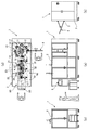
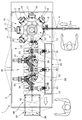
FIG. 1A is a front view showing a blow molding apparatus according to an embodiment, FIG. 1B is a right side view thereof, FIG. 1C is a left side view thereof, and FIG. d) is a plan view showing the internal structure. FIG. 2 is an enlarged plan view showing the internal structure of the blow molding device.
ブロー成形装置1は、横長の直方体形状の装置筐体2の内部に各構成部が配置されている。装置筐体2の正面における右側面の側の部位には、有底筒状の射出成形品であるプリフォーム3の供給レール4(シュート)が配置される(図1(a)、(c)においては供給レール4を省略してある。)。供給レール4は、装置筐体2に向かって下方に傾斜している。プリフォーム3は、後述の図3に示すように、有底筒状の胴部3aと、この胴部3aの先端に形成されている口部3bとを備え、口部3bの外周面には雄ねじが形成されている。プリフォーム3は、不図示の供給元から、供給レール4に対して口部3bがつり下げられた状態で供給される。プリフォーム3は、供給レール4に沿って自重により滑り落ちて、装置筐体2の内部に送り込まれる。
Each component of the blow molding device 1 is arranged inside a horizontally long rectangular
装置筐体2の内部において、その右側面の側には、プリフォーム3の加熱ステーション10が配置されている。加熱ステーション10の左側には、ダブルブロー方式のブローステーション20が配置されている。ブローステーション20の正面側は不良品廃棄ステーション50となっている。ブローステーション20の左側は、ボトル回収ステーション60となっている。装置筐体2の正面における左側面の側の部位には、各部を駆動制御する制御盤5が配置されている。制御盤5には表示画面および各種操作ボタン等が配列されている。予め設定されたシーケンスに従ってブロー成形動作等が行われる。
Inside the
加熱ステーション10は、プリフォーム搬送用の回転円盤11、および、回転円盤11をその中心回りに回転駆動する搬送用モータ、例えば、サーボモータ12を備えている。回転円盤11の外周縁には所定の角度間隔でプリフォーム搬送具13が取り付けられている。図示の例では、等間隔で8か所にプリフォーム搬送具13が配列されている。回転円盤11の回転に伴って、プリフォーム搬送具13は、一点鎖線で示す円形の循環路14に沿って循環する。循環路14における装置筐体2の正面側の部位は、供給レール4からプリフォーム3が送り込まれるプリフォーム供給位置15である。プリフォーム3は、プリフォーム供給位置15において、供給レール4の側から、その口部3bがプリフォーム搬送具13に引き渡される。プリフォーム3は、回転円盤11の回転に伴って、口部3bがつり下げられた状態で、循環路14に沿って搬送される。
The
循環路14において、プリフォーム供給位置15から図において反時計回りに270°回転した位置が、加熱プリフォーム取出し位置16である。循環路14におけるプリフォーム供給位置15から加熱プリフォーム取出し位置16までの間の循環路部分には、等角度間隔で、複数個所、本例では、5か所に、加熱ユニット17が配置されている。各加熱ユニット17は同一構成であり、循環路14の外周側において、その接線方向に延びるヒーターを備えている。また、各加熱ユニット17の加熱位置に送り込まれたプリフォーム3を自転させるための自転用モータ、例えば、サーボモータ18が備わっている。
In the
加熱ステーション10においてブロー成形に適した温度に加熱されたプリフォーム3は、加熱プリフォーム取出し位置16において、ブローステーション20に引き渡される。ブローステーション20には、加熱ステーション10の側に、一次ブロー成形型21が配置され、ボトル回収ステーション60の側に、二次ブロー成形型22が配置されている。一次ブロー成形型21の一次ブロー成形位置23において、プリフォーム3に一次ブロー成形が施されて、一次ブロー成形品である一次ブロー成形ボトル3Aが得られる。一次ブロー成形ボトル3Aは、二次ブロー成形型22の二次ブロー成形位置24において、二次ブロー成形が施されて、二次ブロー成形品である二次ブロー成形ボトル3Bが得られる。本例では、二次ブロー成形ボトル3Bが最終製品のボトルである。
The
加熱プリフォーム取出し位置16と、一次ブロー成形型21による一次ブロー成形位置23との間には、プリフォーム搬送用の第1ロボット31が配置されている。一次ブロー成形型21の一次ブロー成形位置23と、二次ブロー成形型22の二次ブロー成形位置24との間には、一次ブロー成形ボトル3Aを一次ブロー成形位置23から二次ブロー成形位置24に搬送するための第2ロボット32が配置されている。また、二次ブロー成形型22とボトル回収ステーション60との間には、二次ブロー成形ボトル3Bを二次ブロー成形位置24から、成形品回収位置であるボトル回収ステーション60のボトル回収位置62に搬送するための第3ロボット33が配置されている。これら第1、第2および第3ロボット31〜33は共に水平多関節ロボットであり、本例では同一規格のロボットが配置されている。
Between the heated
図3(a)、(b)および(c)は、第1〜第3ロボット31〜33として用いている水平多関節ロボットを示す平面図、正面図および側面図であり、図3(d)はそのグリッパーを示す平面図である。
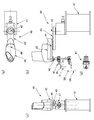
FIGS. 3A, 3B, and 3C are a plan view, a front view, and a side view showing a horizontal articulated robot used as the first to
水平多関節ロボット40は架台41を備えており、架台41には、第1垂直軸線42を中心に旋回可能な状態で、第1水平旋回アーム43が搭載されている。第1水平旋回アーム43の先端部には、第2垂直軸線44を中心に旋回可能な状態で、第2水平旋回アーム45が搭載されている。第2水平旋回アーム45の先端部には、垂直方向に昇降可能な昇降軸46が搭載されている。第2水平旋回アーム45から下方に延びている昇降軸46の下端部には、水平方向に開閉可能なグリッパー47が搭載されている。グリッパー47によって、プリフォーム3、一次ブロー成形ボトル3Aあるいは最終製品である二次ブロー成形ボトル3Bの口部3bの部位を把持可能である。
The horizontal articulated
再び、図2を参照して説明すると、加熱プリフォーム取出し位置16、一次ブロー成形位置23および二次ブロー成形位置24は、一点鎖線で示す直線6上において、同一間隔の位置にある。また、一次ブロー成形型21、二次ブロー成形型22は、それぞれ、左右一対の開閉型からなる。各開閉型は、その開閉中心が直線6に直交する方向における一方の側(本例では背面側)に位置し、開閉側が他方の側(正面側)に位置する。
Referring again to FIG. 2, the heated
また、第1、第2および第3ロボット31〜33のそれぞれは、第1水平旋回アーム43の第1垂直軸線42が直線6上に位置し、グリッパー47が直線6に対して開閉型の開閉側を移動するように、配置されている。本例では、第1ロボット31(その第1垂直軸線42)は、加熱プリフォーム取出し位置16と一次ブロー成形位置23の丁度中間に位置する。同様に、第2ロボット32(その第1垂直軸線42)は、一次ブロー成形位置23と二次ブロー成形位置24の丁度中間に位置する。
In addition, each of the first, second and
不良品廃棄ステーション50において、第1〜第3ロボット31〜33における装置筐体2の正面側の位置には、それぞれ、不良品判別部51〜53が配置されている。第1〜第3ロボット31〜33のそれぞれにおいて、第1、第2水平旋回アーム43、45が正面側に直線状に延びた状態でグリッパー47に把持されているプリフォーム3、一次ブロー成形ボトル3A、二次ブロー成形ボトル3Bは、不良品判別部51〜53の判別位置に位置決めされる。不良品判別部51〜53で不良品であると判別されたプリフォーム3、一次ブロー成形ボトル3A、二次ブロー成形ボトル3Bは、グリッパー47による把持が解除されて、グリッパー47から落下して、下側に位置する不良品廃棄ステーション50の廃棄箱54に回収される。
In the defective discarding
次に、ボトル回収ステーション60には、ボトル回収箱61が配置される。ボトル回収箱61は、例えば、装置筐体2の前後方向あるいは左右方向に移動可能な状態で配置されている。第3ロボット33による二次ブロー成形ボトル3Bのボトル回収位置62を固定した位置に設定できる。この場合には、ボトル回収箱61を例えば不図示の二軸ステージによって前後左右に移動させることで、回収される二次ブロー成形ボトル3Bをボトル回収箱61内に整列状態で回収できる。あるいは、図示のように、第3ロボット33のグリッパー47の移動可能範囲が、ボトル回収箱61の全幅を包含する場合には、ボトル回収箱61の左右方向の移動と、第3ロボット33のボトル回収位置62の前後方向への移動とを、同期をとって行うことで、ボトル回収箱61に、整列状態で二次ブロー成形ボトル3Bを回収できる。
Next, a
上記構成のブロー成形装置1によるボトル成形動作を以下に纏めて説明する。まず、プリフォーム3が供給レール4につり下げられた状態で当該供給レールに沿って落下して、プリフォーム供給位置15に送り込まれる。プリフォーム供給位置15に送り込まれたプリフォーム3は、そこに待機していた回転円盤11のプリフォーム搬送具13に引き渡される。この状態で、搬送用のサーボモータ12によって回転円盤11が一定の送りピッチ分だけ(一定の角度だけ)回転し、プリフォーム3が循環路14に沿って最初の加熱ユニット17の加熱位置に位置決めされる。加熱ユニット17において、自転用のサーボモータ18によって、プリフォーム3はその中心軸線回りに回転する(自転する)。自転するプリフォーム3は、その外側からヒーターによって加熱される。プリフォーム3を内部加熱する場合には、自転しているプリフォーム3の口部を通して、回転盤上部から棒ヒーターをプリフォーム内部に挿入し、プリフォーム3を内側から所定の温度に加熱する。プリフォーム3は、各加熱ユニット17において同様に加熱された後に、加熱プリフォーム取出し位置16に送り出される。
The bottle forming operation of the blow molding apparatus 1 having the above configuration will be described below. First, the
加熱後のプリフォーム3は、第1ロボット31によって、加熱プリフォーム取出し位置16から、型開き状態にある一次ブロー成形型21の一次ブロー成形位置23に送り込まれる。第1ロボット31は搬送途中において、不良品判別部51において一時的に止まり、プリフォーム3の口部3b等の良否判定が行われる。第1ロボット31によって搬送されるプリフォーム3が不良品判別部51の判別位置を所定の速度で通過する間に、不良品判別部51において、通過するプリフォーム3の良否判定を行ってもよい。不良品判別部51において不良品であると判別されたプリフォームは、不良品廃棄ステーション50の廃棄箱54に回収される。
The
プリフォーム3が一次ブロー成形位置23に送り込まれると、一次ブロー成形型21の型締めが行われ、プリフォーム3にブロー成形、例えば、二軸延伸ブロー成形が施される。これにより、プリフォーム3から一次ブロー成形品である一次ブロー成形ボトル3Aが得られる。一次ブロー成形型21の型開き後に、第2ロボット32によって、一次ブロー成形ボトル3Aを、一次ブロー成形位置23から、型開き状態の二次ブロー成形型22の二次ブロー成形位置24に送り込む。一次ブロー成形ボトル3Aは搬送中に放熱により収縮して密度が高まり、耐熱性が付与される。第2ロボット32は、搬送途中において、不良品判別部52において一時的に止まり、不良品判別部52において一次ブロー成形ボトル3Aの良否判定が行われる。第2ロボット32によって搬送される一次ブロー成形ボトル3Aが不良品判別部52の判別位置を所定の速度で通過する間に、不良品判別部52において、通過する一次ブロー成形ボトル3Aの良否判定を行ってもよい。不良品であると判別された一次ブロー成形ボトル3Aは、不良品廃棄ステーション50の廃棄箱54に回収される。
When the
二次ブロー成形位置24に送り込まれた所定の熱収縮状態の一次ブロー成形ボトル3Aは、型閉めした二次ブロー成形型22によって二次ブロー成形される。これにより、二次ブロー成形品である所定サイズの二次ブロー成形ボトル3Bが得られる。二次ブロー成形型22の型開き後に、二次ブロー成形ボトル3Bを、第3ロボット33によって、二次ブロー成形位置24からボトル回収位置62に送り出して、ボトル回収箱61に詰め込む。なお、第3ロボット33は搬送途中において、不良品判別部53において一時的に止まり、良否が判別される。二次ブロー成形ボトル3Bを、不良品判別部53による判別位置において一時的に止めずに、判別位置を所定の速度で通過させる間に、良否判別を行ってもよい。不良品であると判別された二次ブロー成形ボトル3Bは廃棄箱54に回収される。
The primary blow-molded
(実施の形態1の改変例)
図4は上記のブロー成形装置1の改変例を示す説明図である。この図に示すブロー成形装置100の基本構成は、上記のブロー成形装置1と同様であり、プリフォーム103の加熱ステーション110と、ダブルブロー方式のブローステーション120と、ボトル回収ステーション160とを備えている。本例では、加熱ステーション110において2個ずつプリフォーム103が間欠搬送されながら加熱される。そのために、プリフォーム搬送用の回転円盤111の外周縁に沿って等角度間隔で、2個ずつプリフォーム搬送具113が配置されている。また、ブローステーション120では、前後対称な状態に2列のブロー成形ラインが構成されている。
(Modification of First Embodiment)
FIG. 4 is an explanatory view showing a modified example of the blow molding apparatus 1 described above. The basic configuration of the
2列のブロー成形ラインは前後対称な構成となっている。後側のブロー成形ラインにおいて、加熱ステーション110における一方の加熱プリフォーム取出し位置116Aと、一次ブロー成形型121Aによる一次ブロー成形位置123Aとの間には、プリフォーム搬送用の第1ロボット131Aが配置されている。一次ブロー成形型121Aの一次ブロー成形位置123Aと、二次ブロー成形型122Aの二次ブロー成形位置124Aとの間には、一次ブロー成形ボトル103A1を一次ブロー成形位置123Aから二次ブロー成形位置124Aに搬送するための第2ロボット132Aが配置されている。また、二次ブロー成形型122Aとボトル回収ステーション160との間には、二次ブロー成形ボトル103A2を二次ブロー成形位置124Aからボトル回収ステーション160のボトル回収位置162Aに搬送するための第3ロボット133Aが配置されている。これら第1、第2および第3ロボット131A、132A、133Aは共に水平多関節ロボットである。
The two rows of blow molding lines are symmetrical in the front-rear direction. In the rear blow molding line, a
前側のブロー成形ラインも同様に構成されており、加熱プリフォーム取出し位置116Bと、一次ブロー成形型121Bによる一次ブロー成形位置123Bとの間には、プリフォーム搬送用の第1ロボット131Bが配置されている。一次ブロー成形型121Bの一次ブロー成形位置123Bと、二次ブロー成形型122Bの二次ブロー成形位置124Bとの間には、一次ブロー成形ボトル103B1を一次ブロー成形位置123Bから二次ブロー成形位置124Bに搬送するための第2ロボット132Bが配置されている。二次ブロー成形型122Bとボトル回収ステーション160との間には、二次ブロー成形ボトル103B2を二次ブロー成形位置124Bからボトル回収ステーション160のボトル回収位置162Bに搬送するための第3ロボット133Bが配置されている。これら第1、第2および第3ロボット131B、132B、133Bは共に水平多関節ロボットである。
The front blow molding line has the same configuration, and a
このように、2個ずつプリフォームを加熱して2列のブロー成形ラインのそれぞれに供給してブロー成形を行うことで、設置スペースの増加を最小限に抑えながら、処理速度を高めることができる等の利点がある。なお、各部の具体的な構成は、実施の形態1の場合と同様であるので、それらの説明は省略する。 In this manner, by heating the preforms two by two and supplying them to each of the two rows of blow molding lines to perform blow molding, the processing speed can be increased while minimizing the increase in installation space. There are advantages such as. The specific configuration of each unit is the same as that of the first embodiment, and a description thereof will be omitted.
(実施の形態2)
図5は本発明を適用したシングルブロー方式によるブロー成形装置の一例を示す説明図である。本例のブロー成形装置200は、プリフォーム203の加熱ステーション210と、シングルブロー方式のブロー成形ステーション220と、ボトル回収ステーション260とを備えている。また、ブロー成形に適した温度に加熱したプリフォーム203を、加熱プリフォーム取出し位置216から取り出してブロー成形位置223に送り込む第1ロボット231と、プリフォーム203をブロー成形して得られるブロー成形ボトル203Aを、ブロー成形位置223から取り出してボトル回収位置262に送り込む第2ロボット232とを備えている。ブロー成形ステーション220には、ブロー成形位置223においてプリフォーム203にブロー成形を施して、ブロー成形ボトル203Aを成形するブロー成形型221が配置されている。第1、第2ロボット231、232のそれぞれは水平多関節ロボットであり、実施の形態1の場合と同様である。
(Embodiment 2)
FIG. 5 is an explanatory view showing an example of a blow molding apparatus by a single blow method to which the present invention is applied. The
1 ブロー成形装置
2 装置筐体
3 プリフォーム
3A 一次ブロー成形ボトル
3B 二次ブロー成形ボトル
3a 胴部
3b 口部
4 供給レール
5 制御盤
6 直線
10 加熱ステーション
11 回転円盤
12 サーボモータ
13 プリフォーム搬送具
14 循環路
15 プリフォーム供給位置
16 加熱プリフォーム取出し位置
17 加熱ユニット
18 サーボモータ
20 ブローステーション
21 一次ブロー成形型
22 二次ブロー成形型
23 一次ブロー成形位置
24 二次ブロー成形位置
31 第1ロボット
32 第2ロボット
33 第3ロボット
40 水平多関節ロボット
41 架台
42 第1垂直軸線
43 第1水平旋回アーム
44 第2垂直軸線
45 第2水平旋回アーム
46 昇降軸
47 グリッパー
50 不良品廃棄ステーション
51 不良品判別部
52 不良品判別部
53 不良品判別部
54 廃棄箱
60 ボトル回収ステーション
61 ボトル回収箱
62 ボトル回収位置
100 ブロー成形装置
103 プリフォーム
103A1、103B1 一次ブロー成形ボトル
103A2、103B2 二次ブロー成形ボトル
110 加熱ステーション
111 回転円盤
113 プリフォーム搬送具
116A、116B 加熱プリフォーム取出し位置
120 ブローステーション
121A、121B 一次ブロー成形型
122A、122B 二次ブロー成形型
123A、123B 一次ブロー成形位置
124A、124B 二次ブロー成形位置
131A、131B 第1ロボット
132A、132B 第2ロボット
133A、133B 第3ロボット
160 ボトル回収ステーション
162A、162B ボトル回収位置
200 ブロー成形装置
203 プリフォーム
203A ブロー成形ボトル
210 加熱ステーション
216 加熱プリフォーム取出し位置
220 ブローステーション
221 ブロー成形型
223 ブロー成形位置
224 ボトル回収位置
231 第1ロボット
232 第2ロボット
260 ボトル回収ステーション
262 ボトル回収位置
REFERENCE SIGNS LIST 1 blow molding apparatus 2 apparatus casing 3 preform 3A primary blow molded bottle 3B secondary blow molded bottle 3a body 3b mouth 4 supply rail 5 control panel 6 straight line 10 heating station 11 rotating disk 12 servo motor 13 preform carrier 14 Circulation path 15 Preform supply position 16 Heated preform removal position 17 Heating unit 18 Servo motor 20 Blow station 21 Primary blow molding die 22 Secondary blow molding die 23 Primary blow molding position 24 Secondary blow molding position 31 First robot 32 Second robot 33 Third robot 40 Horizontal articulated robot 41 Mount 42 First vertical axis 43 First horizontal swing arm 44 Second vertical axis 45 Second horizontal swing arm 46 Lifting shaft 47 Gripper 50 Defective product disposal station 51 Defective product discrimination Part 52 defective product discriminating part 5 Defective product discriminating unit 54 Waste box 60 Bottle collection station 61 Bottle collection box 62 Bottle collection position 100 Blow molding device 103 Preforms 103A1, 103B1 Primary blow molded bottles 103A2, 103B2 Secondary blow molded bottle 110 Heating station 111 Rotating disk 113 Preform Conveyors 116A, 116B Heated preform removal position 120 Blow stations 121A, 121B Primary blow molding dies 122A, 122B Secondary blow molding dies 123A, 123B Primary blow molding positions 124A, 124B Secondary blow molding positions 131A, 131B First robot 132A , 132B Second robot 133A, 133B Third robot 160 Bottle collection station 162A, 162B Bottle collection position 200 Blow molding apparatus 203 Renovation 203A blow molded bottle 210 heating station 216 heated preform take-out position 220 the blow station 221 blow mold 223 blow molding station 224 Bottle Recycling position 231 first robot 232 second robot 260 bottles recovery station 262 bottle collection position
Claims (8)
プリフォームをブロー成形するブロー成形ステーションと、
ブロー成形品を回収する回収ステーションと、
加熱後の前記プリフォームを、前記加熱ステーションの加熱プリフォーム取出し位置から取り出して、前記ブロー成形ステーションにおける型開き状態にあるブロー成形型によるブロー成形位置に送り込む第1ロボットと、
前記プリフォームをブロー成形して得られる前記ブロー成形品を、型開き状態の前記ブロー成形型による前記ブロー成形位置から取り出して、前記回収ステーションの成形品回収位置に送り込む第2ロボットと、
前記加熱ステーション、前記ブロー成形ステーション、前記回収ステーションおよび前記第1、第2ロボットを駆動制御して、予め設定されたシーケンスに従ってブロー成形動作を行わせる制御盤と、
を有しており、
前記第1、第2ロボットのそれぞれは水平多関節ロボットであり、
前記水平多関節ロボットは、
第1垂直軸線を中心に旋回する第1水平旋回アームと、
前記第1水平旋回アームに搭載され、第2垂直軸線を中心に旋回する第2水平旋回アームと、
前記第2水平旋回アームに搭載され、垂直方向に昇降可能な昇降軸と、
前記プリフォームあるいは前記ブロー成形品における前記ブロー成形が施されない口部の部位を把持するために、前記昇降軸に搭載され、水平方向に開閉するグリッパーと、
を備えており、
前記第1、第2ロボットの前記グリッパーのそれぞれによる前記プリフォーム、前記ブロー成形品の移動経路は、前記制御盤を介して変更可能となっているブロー成形装置。 A heating station for heating the preform;
A blow molding station for blow molding the preform;
A collection station for collecting blow molded products,
A first robot that removes the heated preform from a heated preform removal position of the heating station, and sends the preform to a blow molding position of a blow mold in an open state at the blow molding station ;
A second robot that takes out the blow-molded product obtained by blow-molding the preform from the blow-molding position of the blow-molding die in an open state and sends the blow-molded product to a molded product collection position of the collection station ;
A control panel that drives and controls the heating station, the blow molding station, the collection station, and the first and second robots to perform a blow molding operation according to a preset sequence;
Has,
Each of the first and second robots is a horizontal articulated robot,
The horizontal articulated robot,
A first horizontal pivot arm pivoting about a first vertical axis;
A second horizontal pivot arm mounted on the first horizontal pivot arm and pivoting about a second vertical axis;
An elevating shaft mounted on the second horizontal swing arm and capable of elevating vertically;
A gripper that is mounted on the elevating shaft and opens and closes in the horizontal direction, in order to grip a portion of the mouth of the preform or the blow molded product where the blow molding is not performed,
Equipped with a,
A blow molding apparatus wherein a movement path of the preform and the blow molded product by each of the grippers of the first and second robots can be changed via the control panel .
前記プリフォームをブロー成形するブロー成形ステーションと、
ブロー成形品を回収する回収ステーションと、
加熱後の前記プリフォームを、前記加熱ステーションの加熱プリフォーム取出し位置から取り出して、前記ブロー成形ステーションにおける型開き状態にある一次ブロー成形型による一次ブロー成形位置に送り込む第1ロボットと、
前記プリフォームを一次ブロー成形して得られる一次ブロー成形品を、型開き状態の前記一次ブロー成形型による前記一次ブロー成形位置から取り出して、前記ブロー成形ステーションにおける型開き状態にある二次ブロー成形型による二次ブロー成形位置に送り込む第2ロボットと、
前記一次ブロー成形品を二次ブロー成形して得られる二次ブロー成形品を、型開き状態の前記二次ブロー成形型による前記二次ブロー成形位置から取り出して、前記回収ステーションの成形品回収位置に送り込む第3ロボットと、
前記加熱ステーション、前記ブロー成形ステーション、前記回収ステーションおよび前記第1、第2、第3ロボットを駆動制御して、予め設定されたシーケンスに従ってブロー成形動作を行わせる制御盤と、
を有しており、
前記第1、第2、第3ロボットのそれぞれは水平多関節ロボットであり、
前記水平多関節ロボットは、
第1垂直軸線を中心に旋回する第1水平旋回アームと、
前記第1水平旋回アームに搭載され、第2垂直軸線を中心に旋回する第2水平旋回アームと、
前記第2水平旋回アームに搭載され、垂直方向に昇降可能な昇降軸と、
前記プリフォーム、前記一次ブロー成形品あるいは前記二次ブロー成形品における前記一次あるいは二次ブロー成形が施されない口部の部位を把持するために、前記昇降軸に搭載され、水平方向に開閉するグリッパーと、
を備えており、
前記第1、第2、第3ロボットの前記グリッパーのそれぞれによる前記プリフォーム、前記一次ブロー成形品、前記二次ブロー成形品の移動経路は、前記制御盤を介して変更可能となっているブロー成形装置。 A heating station for heating the preform;
A blow molding station for blow molding the preform;
A collection station for collecting blow molded products ,
A first robot that removes the heated preform from a heated preform removal position of the heating station and feeds the preform to a primary blow molding position by a primary blow molding die in an open state at the blow molding station ;
A primary blow-molded product obtained by primary blow-molding the preform is taken out from the primary blow-molding position by the primary blow-molding mold in the mold open state, and the secondary blow molding in the mold-open state in the blow molding station is performed. A second robot that feeds the mold to a secondary blow molding position,
A secondary blow-molded product obtained by secondary blow-molding the primary blow-molded product is taken out from the secondary blow-molding position by the secondary blow-molding mold in an open state, and a molded product collection position of the collection station is taken out. A third robot to send to the
A control panel that drives and controls the heating station, the blow molding station, the collection station, and the first, second, and third robots to perform a blow molding operation according to a preset sequence;
Has,
Each of the first, second, and third robots is a horizontal articulated robot,
The horizontal articulated robot,
A first horizontal pivot arm pivoting about a first vertical axis;
A second horizontal swing arm mounted on the first horizontal swing arm and swinging about a second vertical axis;
An elevating shaft mounted on the second horizontal swing arm and capable of elevating vertically;
A gripper mounted on the elevating shaft and opened and closed in a horizontal direction in order to grip a portion of the preform, the primary blow molded product or the secondary blow molded product at the opening where the primary or secondary blow molding is not performed. When,
Equipped with a,
The moving path of the preform, the primary blow molded product, and the secondary blow molded product by each of the grippers of the first, second, and third robots can be changed via the control panel. Molding equipment.
前記加熱プリフォーム取出し位置、および、前記一次ブロー成形位置および前記二次ブロー成形位置は、水平方向に延びる直線に沿って、所定の間隔で配置されており、
前記一次ブロー成形型および前記二次ブロー成形型のそれぞれは、前記直線に対して水平方向に直交する直交方向の一方の側に位置する垂直開閉中心線を中心として、前記直交方向の他方の側が開閉する開閉型であり、
前記第1、第2および第3ロボットのそれぞれは、前記第1水平旋回アームの前記第1垂直軸線が前記直線上に位置し、前記グリッパーが前記直線に対して前記開閉型の開閉側を移動するように、配置されているブロー成形装置。 In claim 2,
The heating preform removal position, and the primary blow molding position and the secondary blow molding position are arranged at predetermined intervals along a straight line extending in the horizontal direction ,
Each of the primary blow mold and said secondary blow mold, around a vertical opening center line located on one side of the orthogonal direction orthogonal to the horizontal direction for the straight, other side of the perpendicular direction It is an opening and closing type that opens and closes,
In each of the first, second and third robots, the first vertical axis of the first horizontal swing arm is located on the straight line, and the gripper moves on the open / close side of the open / close type with respect to the straight line. Blow molding equipment is arranged so as to.
前記第1ロボットによって搬送される前記プリフォームの良否を判定し不良品の場合に当該不良品を排出する第1不良品排出部、
前記第2ロボットによって搬送される前記一次ブロー成形品の良否を判定し不良品である場合に当該不良品を排出する第2不良品排出部、および、
前記第3ロボットによって搬送される前記二次ブロー成形品の良否を判定し不良品である場合に当該不良品を排出する第3不良品排出部
のうち、少なくとも一つが配置されているブロー成形装置。 In claim 3,
A first defective product discharging unit that determines quality of the preform conveyed by the first robot and discharges the defective product in the case of a defective product;
A second defective product discharging unit that determines the quality of the primary blow molded product conveyed by the second robot and discharges the defective product if the first blow molded product is defective; and
A blow molding apparatus in which at least one of a third defective product discharge unit that determines the quality of the secondary blow molded product conveyed by the third robot and discharges the defective product if the secondary blow molded product is defective is disposed. .
前記回収ステーションは、前記第3ロボットによって送り出される前記二次ブロー成形品を回収する回収箱を有し、
前記成形品回収位置は、前記回収箱内の位置であり、
前記回収箱は移動可能に配置されているブロー成形装置。 In claim 3,
The collection station has a collection box for collecting the secondary blow-molded product sent out by the third robot,
The molded product collection position is a position in the collection box,
A blow molding device wherein the collection box is movably arranged.
前記加熱ステーションは、
加熱前の前記プリフォームが供給されるプリフォーム供給位置と、
前記プリフォーム供給位置および前記加熱プリフォーム取出し位置を経由する循環路に沿って前記プリフォームを搬送する搬送機構と、
前記循環路に沿って搬送される前記プリフォームを加熱する加熱部と、
を有しているブロー成形装置。 In claim 3,
The heating station comprises:
Preform supply position where the preform before heating is supplied,
A transport mechanism that transports the preform along a circulation path passing through the preform supply position and the heated preform removal position,
A heating unit that heats the preform conveyed along the circulation path,
Blow molding apparatus having
前記搬送機構は、前記プリフォームを円形の前記循環路に沿って搬送する回転盤と、前記回転盤を回転させる搬送用モータとを備え、
前記加熱部は、前記プリフォーム供給位置から前記加熱プリフォーム取出し位置までの間の前記循環路の部分に、所定の間隔で配置した複数の加熱部を備え、
前記加熱部のそれぞれは、当該加熱部の加熱位置を通る前記プリフォームを、その中心軸線回りに自転させる自転用モータを備えているブロー成形装置。 In claim 6,
The transport mechanism includes a rotating disk that transports the preform along the circular circulation path, and a transport motor that rotates the rotating disk,
The heating unit includes a plurality of heating units arranged at predetermined intervals in a portion of the circulation path between the preform supply position and the heated preform removal position,
A blow molding apparatus, wherein each of the heating units includes a rotation motor that rotates the preform passing through a heating position of the heating unit around a central axis thereof.
前記加熱部は、前記プリフォームを外側から加熱する外部加熱部および内側から加熱する内部加熱部のうちの一方あるいは双方を備えているブロー成形装置。 In claim 6 or 7,
The blow molding apparatus, wherein the heating unit includes one or both of an external heating unit that heats the preform from the outside and an internal heating unit that heats the preform from the inside.
Priority Applications (3)
| Application Number | Priority Date | Filing Date | Title |
|---|---|---|---|
| CN201811048855.6A CN109676901A (en) | 2017-10-18 | 2018-09-10 | Blow molding apparatus |
| KR1020180107554A KR20190043462A (en) | 2017-10-18 | 2018-09-10 | Blow molding apparatus |
| TW107132026A TWI763919B (en) | 2017-10-18 | 2018-09-12 | Blow molding device |
Applications Claiming Priority (2)
| Application Number | Priority Date | Filing Date | Title |
|---|---|---|---|
| JP2017202175 | 2017-10-18 | ||
| JP2017202175 | 2017-10-18 |
Publications (3)
| Publication Number | Publication Date |
|---|---|
| JP2019072995A JP2019072995A (en) | 2019-05-16 |
| JP2019072995A5 JP2019072995A5 (en) | 2019-10-10 |
| JP6661133B2 true JP6661133B2 (en) | 2020-03-11 |
Family
ID=66543609
Family Applications (1)
| Application Number | Title | Priority Date | Filing Date |
|---|---|---|---|
| JP2018137239A Active JP6661133B2 (en) | 2017-10-18 | 2018-07-20 | Blow molding equipment |
Country Status (2)
| Country | Link |
|---|---|
| JP (1) | JP6661133B2 (en) |
| TW (1) | TWI763919B (en) |
Families Citing this family (2)
| Publication number | Priority date | Publication date | Assignee | Title |
|---|---|---|---|---|
| CN110026970A (en) * | 2019-05-28 | 2019-07-19 | 山东理工大学 | A kind of SCARA type bottle-making machine Qi Renyiping mechanism |
| CN114505984B (en) * | 2022-03-11 | 2023-10-24 | 广州达意隆包装机械股份有限公司 | Mould changing support and bottle blowing machine |
Family Cites Families (13)
| Publication number | Priority date | Publication date | Assignee | Title |
|---|---|---|---|---|
| JPH06126664A (en) * | 1992-10-15 | 1994-05-10 | Motoda Electron Co Ltd | Load handling device |
| JPH06143397A (en) * | 1992-11-11 | 1994-05-24 | Toyo Seikan Kaisha Ltd | Heat-fixation polyester molded container and manufacture thereof |
| JP4730046B2 (en) * | 2005-10-06 | 2011-07-20 | 東洋製罐株式会社 | Multilayer polyester container and method for producing the same |
| JP4857784B2 (en) * | 2006-01-27 | 2012-01-18 | 東洋製罐株式会社 | Preform removal device |
| WO2009127962A2 (en) * | 2008-04-18 | 2009-10-22 | Sacmi Cooperativa Meccanici Imola Societa' Cooperativa | Method and apparatuses |
| EP2335903A4 (en) * | 2008-09-12 | 2015-07-01 | Nissei Asb Machine Co Ltd | Rotary blow molding device |
| JP5585128B2 (en) * | 2009-03-10 | 2014-09-10 | 大日本印刷株式会社 | Beverage filling method and apparatus |
| ITRM20130035A1 (en) * | 2013-01-21 | 2014-07-22 | Sipa Soc Industrializzazione Progettazione | ROTARY JOINT FOR A PLASTIC TRANSFER MADE FROM AN EXTRUDER TO MOLDS OF A PREFORMING ROTARY MOLDING MACHINE |
| DE102014005321A1 (en) * | 2014-04-10 | 2015-10-15 | Khs Corpoplast Gmbh | Apparatus and method for transporting and handling containers |
| EP3157731B1 (en) * | 2014-06-18 | 2019-12-11 | Discma AG | Method and machine for producing containers by injecting a liquid inside successive preforms |
| JP2016210089A (en) * | 2015-05-08 | 2016-12-15 | 東洋製罐株式会社 | Production method for thin-walled heat resistant polyester bottle |
| EP3437828B1 (en) * | 2016-03-30 | 2021-05-05 | Nissei ASB Machine Co., Ltd. | Blow molding device |
| CN107031025A (en) * | 2017-04-13 | 2017-08-11 | 浙江乐宝塑料设备厂 | Continuously shaped all-in-one for plastic containers |
-
2018
- 2018-07-20 JP JP2018137239A patent/JP6661133B2/en active Active
- 2018-09-12 TW TW107132026A patent/TWI763919B/en active
Also Published As
| Publication number | Publication date |
|---|---|
| TW201930051A (en) | 2019-08-01 |
| TWI763919B (en) | 2022-05-11 |
| JP2019072995A (en) | 2019-05-16 |
Similar Documents
| Publication | Publication Date | Title |
|---|---|---|
| EP0534367B1 (en) | Apparatus for conditioning pressure molded plastic articles | |
| JP5739330B2 (en) | Plant for blow molding plastic containers, especially bottles | |
| JP2009523636A (en) | Equipment for blow molding containers | |
| US20120161372A1 (en) | Method and apparatus for blow molding and for filling containers | |
| JP6661133B2 (en) | Blow molding equipment | |
| KR20110033815A (en) | Moulding unit for a plant for blow-moulding plastic containers, particularly bottles | |
| US7946836B2 (en) | Injection molding and temperature conditioning apparatus | |
| JPS58186587A (en) | Article conveyor and gripper used for said device | |
| KR20110033856A (en) | Moulding unit for a plant for blow-moulding plastic containers, particularly bottles | |
| WO2016136129A1 (en) | Container manufacturing device | |
| JP2010064454A (en) | Rotary-type molded article conveyance device and rotary-type blow molding device using the same | |
| KR20110033855A (en) | Plant for blow-moulding plastic containers, particularly bottles | |
| CN113661043A (en) | Cooling mold, and apparatus and method for manufacturing resin molded article | |
| US11273591B2 (en) | Blow moulding machine system and method | |
| KR20190043462A (en) | Blow molding apparatus | |
| JPH01133715A (en) | Transfer device in plastic hollow vessel manufacturing machine | |
| JP2007044992A (en) | Apparatus for molding synthetic resin container | |
| JPH0911325A (en) | Blow molding method | |
| JP4128331B2 (en) | Device for transferring ordered bottles of thermoplastic material in sequence | |
| US3864445A (en) | Grasping parison preform at right angle to mold parting line | |
| EP3254825B1 (en) | Machine for moulding and blow-moulding containers obtained from corresponding parisons of a thermoplastic material | |
| JPH03224715A (en) | Double-stage orientation blow molding device | |
| JP3442141B2 (en) | Blow molding equipment | |
| US20230257245A1 (en) | Apparatus and method for manufacturing plastic containers with container rotation on transfer starwheels | |
| JP2011073462A (en) | Molding device for molding synthetic resin-made vessel |
Legal Events
| Date | Code | Title | Description |
|---|---|---|---|
| A521 | Request for written amendment filed |
Free format text: JAPANESE INTERMEDIATE CODE: A523 Effective date: 20190830 |
|
| A621 | Written request for application examination |
Free format text: JAPANESE INTERMEDIATE CODE: A621 Effective date: 20190830 |
|
| A871 | Explanation of circumstances concerning accelerated examination |
Free format text: JAPANESE INTERMEDIATE CODE: A871 Effective date: 20190830 |
|
| A975 | Report on accelerated examination |
Free format text: JAPANESE INTERMEDIATE CODE: A971005 Effective date: 20191118 |
|
| A131 | Notification of reasons for refusal |
Free format text: JAPANESE INTERMEDIATE CODE: A131 Effective date: 20191126 |
|
| A521 | Request for written amendment filed |
Free format text: JAPANESE INTERMEDIATE CODE: A523 Effective date: 20200110 |
|
| TRDD | Decision of grant or rejection written | ||
| A01 | Written decision to grant a patent or to grant a registration (utility model) |
Free format text: JAPANESE INTERMEDIATE CODE: A01 Effective date: 20200128 |
|
| A61 | First payment of annual fees (during grant procedure) |
Free format text: JAPANESE INTERMEDIATE CODE: A61 Effective date: 20200129 |
|
| R150 | Certificate of patent or registration of utility model |
Ref document number: 6661133 Country of ref document: JP Free format text: JAPANESE INTERMEDIATE CODE: R150 |
|
| R250 | Receipt of annual fees |
Free format text: JAPANESE INTERMEDIATE CODE: R250 |