JP6660127B2 - Image processing apparatus and method, and image forming apparatus - Google Patents
Image processing apparatus and method, and image forming apparatus Download PDFInfo
- Publication number
- JP6660127B2 JP6660127B2 JP2015182227A JP2015182227A JP6660127B2 JP 6660127 B2 JP6660127 B2 JP 6660127B2 JP 2015182227 A JP2015182227 A JP 2015182227A JP 2015182227 A JP2015182227 A JP 2015182227A JP 6660127 B2 JP6660127 B2 JP 6660127B2
- Authority
- JP
- Japan
- Prior art keywords
- gloss
- image
- data
- recording
- color
- Prior art date
- Legal status (The legal status is an assumption and is not a legal conclusion. Google has not performed a legal analysis and makes no representation as to the accuracy of the status listed.)
- Active
Links
- 238000012545 processing Methods 0.000 title claims description 180
- 238000000034 method Methods 0.000 title claims description 66
- 239000000463 material Substances 0.000 claims description 115
- 238000007639 printing Methods 0.000 claims description 36
- 238000000926 separation method Methods 0.000 claims description 36
- 239000011159 matrix material Substances 0.000 claims description 35
- 230000008569 process Effects 0.000 claims description 31
- 238000003672 processing method Methods 0.000 claims description 5
- 239000012141 concentrate Substances 0.000 claims 1
- 230000007274 generation of a signal involved in cell-cell signaling Effects 0.000 description 22
- 238000010586 diagram Methods 0.000 description 17
- 238000012986 modification Methods 0.000 description 15
- 230000004048 modification Effects 0.000 description 13
- 238000000354 decomposition reaction Methods 0.000 description 12
- 230000010365 information processing Effects 0.000 description 11
- 239000000049 pigment Substances 0.000 description 8
- 238000005286 illumination Methods 0.000 description 7
- 230000008859 change Effects 0.000 description 6
- 238000006243 chemical reaction Methods 0.000 description 6
- 239000003086 colorant Substances 0.000 description 6
- 230000003746 surface roughness Effects 0.000 description 6
- 238000009792 diffusion process Methods 0.000 description 4
- 239000006185 dispersion Substances 0.000 description 4
- 238000013507 mapping Methods 0.000 description 4
- 238000003860 storage Methods 0.000 description 4
- 238000004040 coloring Methods 0.000 description 3
- 238000012937 correction Methods 0.000 description 3
- 230000006870 function Effects 0.000 description 3
- 238000012360 testing method Methods 0.000 description 3
- XAGFODPZIPBFFR-UHFFFAOYSA-N aluminium Chemical compound [Al] XAGFODPZIPBFFR-UHFFFAOYSA-N 0.000 description 2
- 229910052782 aluminium Inorganic materials 0.000 description 2
- 230000002457 bidirectional effect Effects 0.000 description 2
- 239000000843 powder Substances 0.000 description 2
- 239000011347 resin Substances 0.000 description 2
- 229920005989 resin Polymers 0.000 description 2
- 230000002411 adverse Effects 0.000 description 1
- 239000010407 anodic oxide Substances 0.000 description 1
- 230000015572 biosynthetic process Effects 0.000 description 1
- 238000000576 coating method Methods 0.000 description 1
- 230000000295 complement effect Effects 0.000 description 1
- 230000008878 coupling Effects 0.000 description 1
- 238000010168 coupling process Methods 0.000 description 1
- 238000005859 coupling reaction Methods 0.000 description 1
- 238000013461 design Methods 0.000 description 1
- 238000009826 distribution Methods 0.000 description 1
- 230000000694 effects Effects 0.000 description 1
- 238000005516 engineering process Methods 0.000 description 1
- 238000009499 grossing Methods 0.000 description 1
- 239000004816 latex Substances 0.000 description 1
- 229920000126 latex Polymers 0.000 description 1
- 239000007788 liquid Substances 0.000 description 1
- 238000000691 measurement method Methods 0.000 description 1
- 230000000717 retained effect Effects 0.000 description 1
- 238000007788 roughening Methods 0.000 description 1
- 230000035807 sensation Effects 0.000 description 1
- 239000002904 solvent Substances 0.000 description 1
- 238000005092 sublimation method Methods 0.000 description 1
- 230000009469 supplementation Effects 0.000 description 1
- 230000001502 supplementing effect Effects 0.000 description 1
- 238000010998 test method Methods 0.000 description 1
- 230000000007 visual effect Effects 0.000 description 1
Images


Classifications
-
- H—ELECTRICITY
- H04—ELECTRIC COMMUNICATION TECHNIQUE
- H04N—PICTORIAL COMMUNICATION, e.g. TELEVISION
- H04N1/00—Scanning, transmission or reproduction of documents or the like, e.g. facsimile transmission; Details thereof
- H04N1/40—Picture signal circuits
- H04N1/40087—Multi-toning, i.e. converting a continuous-tone signal for reproduction with more than two discrete brightnesses or optical densities, e.g. dots of grey and black inks on white paper
-
- B—PERFORMING OPERATIONS; TRANSPORTING
- B41—PRINTING; LINING MACHINES; TYPEWRITERS; STAMPS
- B41J—TYPEWRITERS; SELECTIVE PRINTING MECHANISMS, i.e. MECHANISMS PRINTING OTHERWISE THAN FROM A FORME; CORRECTION OF TYPOGRAPHICAL ERRORS
- B41J19/00—Character- or line-spacing mechanisms
- B41J19/14—Character- or line-spacing mechanisms with means for effecting line or character spacing in either direction
- B41J19/142—Character- or line-spacing mechanisms with means for effecting line or character spacing in either direction with a reciprocating print head printing in both directions across the paper width
- B41J19/145—Dot misalignment correction
-
- B—PERFORMING OPERATIONS; TRANSPORTING
- B41—PRINTING; LINING MACHINES; TYPEWRITERS; STAMPS
- B41J—TYPEWRITERS; SELECTIVE PRINTING MECHANISMS, i.e. MECHANISMS PRINTING OTHERWISE THAN FROM A FORME; CORRECTION OF TYPOGRAPHICAL ERRORS
- B41J2/00—Typewriters or selective printing mechanisms characterised by the printing or marking process for which they are designed
- B41J2/005—Typewriters or selective printing mechanisms characterised by the printing or marking process for which they are designed characterised by bringing liquid or particles selectively into contact with a printing material
- B41J2/01—Ink jet
- B41J2/205—Ink jet for printing a discrete number of tones
- B41J2/2052—Ink jet for printing a discrete number of tones by dot superpositioning, e.g. multipass doubling
-
- B—PERFORMING OPERATIONS; TRANSPORTING
- B41—PRINTING; LINING MACHINES; TYPEWRITERS; STAMPS
- B41J—TYPEWRITERS; SELECTIVE PRINTING MECHANISMS, i.e. MECHANISMS PRINTING OTHERWISE THAN FROM A FORME; CORRECTION OF TYPOGRAPHICAL ERRORS
- B41J2/00—Typewriters or selective printing mechanisms characterised by the printing or marking process for which they are designed
- B41J2/005—Typewriters or selective printing mechanisms characterised by the printing or marking process for which they are designed characterised by bringing liquid or particles selectively into contact with a printing material
- B41J2/01—Ink jet
- B41J2/21—Ink jet for multi-colour printing
- B41J2/2107—Ink jet for multi-colour printing characterised by the ink properties
- B41J2/2114—Ejecting specialized liquids, e.g. transparent or processing liquids
- B41J2/2117—Ejecting white liquids
-
- B—PERFORMING OPERATIONS; TRANSPORTING
- B41—PRINTING; LINING MACHINES; TYPEWRITERS; STAMPS
- B41J—TYPEWRITERS; SELECTIVE PRINTING MECHANISMS, i.e. MECHANISMS PRINTING OTHERWISE THAN FROM A FORME; CORRECTION OF TYPOGRAPHICAL ERRORS
- B41J2/00—Typewriters or selective printing mechanisms characterised by the printing or marking process for which they are designed
- B41J2/005—Typewriters or selective printing mechanisms characterised by the printing or marking process for which they are designed characterised by bringing liquid or particles selectively into contact with a printing material
- B41J2/01—Ink jet
- B41J2/21—Ink jet for multi-colour printing
- B41J2/2132—Print quality control characterised by dot disposition, e.g. for reducing white stripes or banding
-
- G—PHYSICS
- G06—COMPUTING; CALCULATING OR COUNTING
- G06K—GRAPHICAL DATA READING; PRESENTATION OF DATA; RECORD CARRIERS; HANDLING RECORD CARRIERS
- G06K15/00—Arrangements for producing a permanent visual presentation of the output data, e.g. computer output printers
- G06K15/02—Arrangements for producing a permanent visual presentation of the output data, e.g. computer output printers using printers
- G06K15/021—Adaptations for printing on specific media
-
- G—PHYSICS
- G06—COMPUTING; CALCULATING OR COUNTING
- G06K—GRAPHICAL DATA READING; PRESENTATION OF DATA; RECORD CARRIERS; HANDLING RECORD CARRIERS
- G06K15/00—Arrangements for producing a permanent visual presentation of the output data, e.g. computer output printers
- G06K15/02—Arrangements for producing a permanent visual presentation of the output data, e.g. computer output printers using printers
- G06K15/10—Arrangements for producing a permanent visual presentation of the output data, e.g. computer output printers using printers by matrix printers
- G06K15/102—Arrangements for producing a permanent visual presentation of the output data, e.g. computer output printers using printers by matrix printers using ink jet print heads
- G06K15/105—Multipass or interlaced printing
- G06K15/107—Mask selection
-
- G—PHYSICS
- G06—COMPUTING; CALCULATING OR COUNTING
- G06K—GRAPHICAL DATA READING; PRESENTATION OF DATA; RECORD CARRIERS; HANDLING RECORD CARRIERS
- G06K15/00—Arrangements for producing a permanent visual presentation of the output data, e.g. computer output printers
- G06K15/02—Arrangements for producing a permanent visual presentation of the output data, e.g. computer output printers using printers
- G06K15/18—Conditioning data for presenting it to the physical printing elements
- G06K15/1801—Input data handling means
- G06K15/1822—Analysing the received data before processing
- G06K15/1823—Analysing the received data before processing for evaluating the resources needed, e.g. rasterizing time, ink, paper stock
-
- H—ELECTRICITY
- H04—ELECTRIC COMMUNICATION TECHNIQUE
- H04N—PICTORIAL COMMUNICATION, e.g. TELEVISION
- H04N1/00—Scanning, transmission or reproduction of documents or the like, e.g. facsimile transmission; Details thereof
- H04N1/40—Picture signal circuits
- H04N1/405—Halftoning, i.e. converting the picture signal of a continuous-tone original into a corresponding signal showing only two levels
- H04N1/4051—Halftoning, i.e. converting the picture signal of a continuous-tone original into a corresponding signal showing only two levels producing a dispersed dots halftone pattern, the dots having substantially the same size
- H04N1/4052—Halftoning, i.e. converting the picture signal of a continuous-tone original into a corresponding signal showing only two levels producing a dispersed dots halftone pattern, the dots having substantially the same size by error diffusion, i.e. transferring the binarising error to neighbouring dot decisions
- H04N1/4053—Halftoning, i.e. converting the picture signal of a continuous-tone original into a corresponding signal showing only two levels producing a dispersed dots halftone pattern, the dots having substantially the same size by error diffusion, i.e. transferring the binarising error to neighbouring dot decisions with threshold modulated relative to input image data or vice versa
-
- H—ELECTRICITY
- H04—ELECTRIC COMMUNICATION TECHNIQUE
- H04N—PICTORIAL COMMUNICATION, e.g. TELEVISION
- H04N1/00—Scanning, transmission or reproduction of documents or the like, e.g. facsimile transmission; Details thereof
- H04N1/40—Picture signal circuits
- H04N1/405—Halftoning, i.e. converting the picture signal of a continuous-tone original into a corresponding signal showing only two levels
- H04N1/4055—Halftoning, i.e. converting the picture signal of a continuous-tone original into a corresponding signal showing only two levels producing a clustered dots or a size modulated halftone pattern
-
- H—ELECTRICITY
- H04—ELECTRIC COMMUNICATION TECHNIQUE
- H04N—PICTORIAL COMMUNICATION, e.g. TELEVISION
- H04N1/00—Scanning, transmission or reproduction of documents or the like, e.g. facsimile transmission; Details thereof
- H04N1/46—Colour picture communication systems
- H04N1/52—Circuits or arrangements for halftone screening
-
- H—ELECTRICITY
- H04—ELECTRIC COMMUNICATION TECHNIQUE
- H04N—PICTORIAL COMMUNICATION, e.g. TELEVISION
- H04N1/00—Scanning, transmission or reproduction of documents or the like, e.g. facsimile transmission; Details thereof
- H04N1/46—Colour picture communication systems
- H04N1/54—Conversion of colour picture signals to a plurality of signals some of which represent particular mixed colours, e.g. for textile printing
-
- H—ELECTRICITY
- H04—ELECTRIC COMMUNICATION TECHNIQUE
- H04N—PICTORIAL COMMUNICATION, e.g. TELEVISION
- H04N1/00—Scanning, transmission or reproduction of documents or the like, e.g. facsimile transmission; Details thereof
- H04N1/46—Colour picture communication systems
- H04N1/56—Processing of colour picture signals
- H04N1/60—Colour correction or control
- H04N1/6097—Colour correction or control depending on the characteristics of the output medium, e.g. glossy paper, matt paper, transparency or fabrics
-
- B—PERFORMING OPERATIONS; TRANSPORTING
- B41—PRINTING; LINING MACHINES; TYPEWRITERS; STAMPS
- B41J—TYPEWRITERS; SELECTIVE PRINTING MECHANISMS, i.e. MECHANISMS PRINTING OTHERWISE THAN FROM A FORME; CORRECTION OF TYPOGRAPHICAL ERRORS
- B41J19/00—Character- or line-spacing mechanisms
- B41J19/14—Character- or line-spacing mechanisms with means for effecting line or character spacing in either direction
- B41J19/142—Character- or line-spacing mechanisms with means for effecting line or character spacing in either direction with a reciprocating print head printing in both directions across the paper width
-
- B—PERFORMING OPERATIONS; TRANSPORTING
- B41—PRINTING; LINING MACHINES; TYPEWRITERS; STAMPS
- B41J—TYPEWRITERS; SELECTIVE PRINTING MECHANISMS, i.e. MECHANISMS PRINTING OTHERWISE THAN FROM A FORME; CORRECTION OF TYPOGRAPHICAL ERRORS
- B41J2/00—Typewriters or selective printing mechanisms characterised by the printing or marking process for which they are designed
- B41J2/005—Typewriters or selective printing mechanisms characterised by the printing or marking process for which they are designed characterised by bringing liquid or particles selectively into contact with a printing material
- B41J2/01—Ink jet
- B41J2/205—Ink jet for printing a discrete number of tones
- B41J2/2054—Ink jet for printing a discrete number of tones by the variation of dot disposition or characteristics, e.g. dot number density, dot shape
Landscapes
- Engineering & Computer Science (AREA)
- Multimedia (AREA)
- Signal Processing (AREA)
- Physics & Mathematics (AREA)
- General Physics & Mathematics (AREA)
- Theoretical Computer Science (AREA)
- General Engineering & Computer Science (AREA)
- Quality & Reliability (AREA)
- Textile Engineering (AREA)
- Mathematical Physics (AREA)
- Discrete Mathematics (AREA)
- Facsimile Image Signal Circuits (AREA)
- Image Processing (AREA)
- Color, Gradation (AREA)
- Color Image Communication Systems (AREA)
Description
本発明は、形成する画像の光沢性の制御に関する。 The present invention relates to controlling glossiness of an image to be formed.
商業印刷など分野において、印刷物に対する高級化および個性化の要求が高まっている。これら要求を実現する方法として、印刷物の光沢性を制御する技術がある。当該技術として、光沢調整材の使用量を制御する方法(特許文献1)、ドット配置の集中度を制御して均一な光沢性を実現する方法(特許文献2)、記録走査回数を色材ごとに異ならせて均一な光沢性を実現する方法(特許文献3)が知られている。これらの技術においては、光沢制御と同時に、カラー画像について画質弊害が生じないことが求められる。 In the field of commercial printing and the like, demands for higher quality and individualization of printed matter are increasing. As a method for realizing these requirements, there is a technique for controlling glossiness of a printed matter. Such techniques include a method of controlling the amount of gloss adjusting material used (Patent Document 1), a method of controlling the degree of concentration of dot arrangement to achieve uniform gloss (Patent Document 2), and the number of printing scans for each color material. There has been known a method of achieving uniform glossiness by varying the thickness (Patent Document 3). In these techniques, it is required that the quality of the color image is not adversely affected at the same time as the gloss control.
特許文献2の技術によれば、画像内の所定領域における光沢性の制御が可能であるが、再現可能な光沢の階調数がドット配置の種類の数に制限される。特許文献3の技術によれば、再現可能な光沢の階調数が走査回数の種類の数に制限される。従って、これらの技術によれば、光沢の階調数が少なく、滑らかな光沢変化を得ることが難しい。
According to the technique of
一方、特許文献1の技術によれば、再現可能な光沢の階調数が光沢調整材の使用量によって決まり、滑らかな光沢変化を得ることが可能になる。しかし、光沢調整材の使用量のみで制御可能な光沢範囲(ダイナミックレンジ)はあまり広くない。このように、従来の光沢性の制御技術は、広いダイナミックレンジにおいて光沢の滑らかな階調再現を得ることが難しい。
On the other hand, according to the technique of
本発明は、形成される画像において滑らかな階調再現を得ることを目的とする。 An object of the present invention is to obtain smooth gradation reproduction in an image to be formed.
本発明は、前記の目的を達成する一手段として、以下の構成を備える。 The present invention has the following configuration as one means for achieving the above object.
本発明にかかる画像処理装置は、画像の色を表す第一のデータと、前記画像の光沢に関する第二のデータと、を入力する入力手段と、前記第一のデータに基づいて、前記画像を記録媒体上に形成するための記録材の記録量を決定する第一の決定手段と、前記決定された記録量に対する前記第二のデータに応じたハーフトーン処理によって、前記記録媒体上を複数回記録走査して前記画像を形成する際の前記記録材のドット配置を決定する第二の決定手段と、を有する。 The image processing device according to the present invention, the first data representing the color of the image, the second data relating to the gloss of the image, input means for inputting, based on the first data, the image a first determining means for determining the recording amount of the recording material for forming on a recording medium, the halftone process in accordance with the second data to the recording amount of pre Symbol determined, a plurality of upper said recording medium Second determining means for determining the dot arrangement of the recording material when forming the image by performing multiple recording scans.
本発明によれば、形成される画像において滑らかな階調再現を得ることができる。 According to the present invention, smooth gradation reproduction can be obtained in an image to be formed.
以下、本発明にかかる実施例の画像処理装置および画像処理方法を図面を参照して詳細に説明する。なお、実施例は特許請求の範囲にかかる本発明を限定するものではなく、また、実施例において説明する構成の組み合わせのすべてが本発明の解決手段に必須とは限らない。 Hereinafter, an image processing apparatus and an image processing method according to embodiments of the present invention will be described in detail with reference to the drawings. It should be noted that the embodiments do not limit the present invention according to the claims, and all combinations of the configurations described in the embodiments are not necessarily essential to the solution of the present invention.
[光沢写像性]
以下では、画像処理装置の入力情報として、色画像データおよび光沢画像データを用いる例を説明する。色画像データは、各色8ビット3チャネルのRGB画像データとする。光沢画像データは、8ビット1チャネルのモノクロ画像データとし、値が大きいほど光沢が高いことを表す。
[Gloss image clarity]
Hereinafter, an example in which color image data and gloss image data are used as input information of the image processing apparatus will be described. The color image data is 8-bit 3-channel RGB image data for each color. The glossy image data is 8-bit, one-channel monochrome image data, and the larger the value, the higher the glossiness.
光沢値としては、非特許文献1に定められた光沢写像性の値を用いるが、光沢値の定義は限定されず、例えば、光沢の強度や彩度を光沢値としてもよい。光沢写像性の値が大きい場合に照明像が鮮明であり、逆に値が小さい場合に照明像が不鮮明であることを示す。なお、色画像データと光沢画像データのサイズおよび解像度は同一とする。
As the gloss value, a value of gloss image clarity defined in Non-Patent
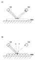
光沢写像性は、印刷物の表面形状との関連性が高いことが知られている。図1により表面形状と光沢写像性の関係を説明する。図1は、照明101から照射された光が印刷物102の表面で反射し、観察者103に光沢として知覚される様子を示す。図1(a)に示すように、表面凹凸が小さく平滑度が高い印刷物102aの場合、印刷物102aに写り込む照明像の反射方向が均一である。一方、図1(b)に示すように、表面凹凸が大きく平滑度が低い印刷物102bの場合、印刷物102bに写り込む照明光の反射方向は不均一である。
It is known that gloss clarity is highly related to the surface shape of printed matter. The relationship between the surface shape and gloss clarity will be described with reference to FIG. FIG. 1 shows a state in which light emitted from the
照明光の反射方向が不均一になると、照明像の鮮明度が低下し、光沢写像性が低下する。つまり、光沢写像性を低くするには印刷物の表面形状を粗くし、光沢写像性を高くするには印刷物の表面形状を平滑化すればよい。従って、詳細は後述するが、表面形状が平滑になる印刷条件と、表面形状が粗くなる印刷条件を保持して、領域ごとに印刷条件を切り替えれば、任意の光沢写像性の再現が可能になる。 When the reflection direction of the illumination light is not uniform, the sharpness of the illumination image is reduced, and the gloss image clarity is reduced. That is, the surface shape of the printed matter may be roughened to reduce the gloss image clarity, and the surface shape of the printed matter may be smoothed to increase the gloss image clarity. Therefore, although the details will be described later, by maintaining the printing conditions for smoothing the surface shape and the printing conditions for roughening the surface shape and switching the printing conditions for each area, it is possible to reproduce any gloss clarity. .
[装置の構成]
図2のブロック図により実施例1の画像処理装置12の構成例を示す。図2において、入力部101は、情報処理装置11から入力した、印刷対象の画像の各画素の色を表す色画像データRGBを色画像バッファ102に格納する。また、入力部101は、情報処理装置11から入力した、印刷対象の画像の各画素の光沢写像性を表す光沢画像データGlを光沢画像バッファ103に格納する。
[Device configuration]
An example of the configuration of the
色画像データRGBおよび光沢画像データGlは、コンピュータ装置である情報処理装置11において稼働する各種アプリケーションによって作成、編集または加工されたデータであり、色画像データRGBは例えばsRGBデータである。色画像データRGBおよび光沢画像データGlは、情報処理装置11に限らず、画像入力デバイス、メモリカードなどの記録メディア、ウェブサイトなどから取得してもよい。また、入力部101としては、USBのようなシリアルバスインタフェイス、有線または無線LANのようなネットワークインタフェイスが利用可能である。
The color image data RGB and the gloss image data Gl are data created, edited or processed by various applications running on the
切替信号生成部104は、所定領域ごとに、多値の光沢画像データGlを二値の切替信号GCに変換する。切替信号GCは画像処理条件を示す信号であり、例えば、‘1’が高光沢用の画像処理を示し、‘0’が低光沢用の画像処理を示す。
The
所定領域として光沢画像データGlの最少単位である画素を用いればよいが、印刷物の観察時に、複数の領域における光沢写像性を面積階調として表現可能であればよく、複数画素からなるブロック領域を所定領域としてもよい。また、以下では、高光沢用と低光沢用の二種類の画像処理を備える例を説明するが、三階調以上の光沢値を再現するために三種類以上の画像処理を備える場合は、その分、切替信号GCのビット数を増やせばよい。 A pixel which is the minimum unit of the gloss image data Gl may be used as the predetermined area.However, when observing a printed matter, it is sufficient that the gloss clarity in a plurality of areas can be expressed as area gradation, and a block area including a plurality of pixels is used. It may be a predetermined area. In the following, an example will be described in which two types of image processing for high gloss and for low gloss are provided, but in the case where three or more types of image processing are provided in order to reproduce gloss values of three or more gradations, It is sufficient to increase the number of bits of the switching signal GC.
記録材量決定部105は、切替信号GCに基づき、色画像データRGBを画像形成装置13が備える有色記録材(以下、色材)それぞれの量および無色透明の記録材(以下、クリア材)の量を示す多値の記録材量データに変換する。この変換処理を「色分解処理」と呼ぶことにする。なお、クリア材は、僅かな色や濁りがあってもよく、ほぼ無色透明の記録材であればよい。
Based on the switching signal GC, the recording material
ハーフトーン処理部106は、切替信号GCに基づき、記録材量決定部105が出力する記録材量データに疑似中間調処理を施して、記録材ごとに、多値の記録材量データを、例えば、オンドットの記録位置を示す二値の記録信号に変換する。オンドットは、記録材の打ち込みにより形成されるドットのことである。また、疑似中間調処理としては、例えばディザ処理や誤差拡散処理を利用すればよい。
The
パス分解部107は、切替信号GCに基づき、ハーフトーン処理部106が出力する記録信号をマルチパス記録方式における各記録走査(パス)に分解するパス分解処理を行い、画像形成装置13が備える記録ヘッドの記録素子の駆動データを生成する。
The
出力データバッファ108は、パス分解部107が出力する駆動データを画像形成データとして格納する。出力データバッファ108に格納された画像形成データは、画像形成装置13の画像形成動作に同期して、出力部109を介して画像形成装置13に出力される。出力部109としては、USB、eSATA、PCI、PCIe(登録商標)などの汎用インタフェイスや専用インタフェイスが利用可能である
The
[画像形成装置と情報処理装置]
画像形成装置13の構成の詳細は省略するが、画像形成装置13は、記録媒体に対して記録ヘッドを相対的に縦横に移動して、画像形成データが表す各色材の二値画像を記録媒体上に記録する。また、画像形成装置13は、記録媒体上を記録ヘッドによって複数回走査して画像を完成させるマルチパス記録方式を採用し、記録ヘッドの往路走査と復路走査の何れにおいても記録動作を行う所謂双方向印刷方式を採用する。
[Image Forming Apparatus and Information Processing Apparatus]
Although the details of the configuration of the
図17のブロック図により情報処理装置11の構成例を示す。CPU171は、RAM173をワークメモリとして、ROM172や記憶部179に格納されたOSや各種プログラムを実行し、システムバス178を介して後述する各部を制御する。
An example of the configuration of the
記憶部179は、例えばSATAインタフェイス(I/F)を介してシステムバス178に接続されるHDD、SSD、フラッシュメモリなどである。汎用I/F175は、USBなどのシリアルバスインタフェイスであり、マウスやキーボードなどの入力デバイス14、画像形成装置13、記録メディア用の汎用ドライブ17などが接続される。
The
CPU171は、入力デバイス14を介してユーザが指定するプログラムを記録部179からRAM173にロードし、当該プログラムを実行してビデオカード(VC)174に接続されたモニタ16にユーザインタフェイスを表示する。ユーザは、当該ユーザインタフェイスを利用して、画像処理装置12に入力する色画像データや光沢画像データの選択、作成、編集を行う。なお、色画像データや光沢画像データまたはそれら画像データの基になるデータが記憶部179や汎用ドライブ17の記録メディアに格納されている。
The
ネットワークインタフェイスカード(NIC)177は、情報処理装置11を有線LANまたは無線LANなどのネットワークに接続するためのネットワークインタフェイスである。情報処理装置11が実行するプログラム、色画像データや光沢画像データまたはそれら画像データの基になるデータはネットワーク上のサーバ装置に格納されていてもよい。
The network interface card (NIC) 177 is a network interface for connecting the
画像処理装置12の処理および機能は、情報処理装置11が実行する画像形成装置13用のプリンタドライバによって実現可能である。勿論、画像処理装置12をハードウェアとして画像形成装置13に組み込むことも可能である。
The processing and functions of the
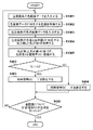
[画像処理]
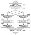
図3のフローチャートにより画像処理装置12による画像形成データの生成処理を説明する。入力部101は、色画像データRGBと光沢画像データGlを入力し、それらを色画像バッファ102と光沢画像バッファ103にそれぞれ格納する(S301)。切替信号生成部104は、光沢画像データGIに疑似中間調処理を施し、例えば画素ごとに、切替信号GCを生成する(S302)。
[Image processing]
The generation processing of the image forming data by the
記録材量決定部105は、画素ごとに、切替信号GCに応じて色分解処理に用いるテーブルを切り替えて、色画像データRGBを記録材量データに変換する。つまり、記録材量決定部105は、GC=‘0’の場合は低光沢用の色分解ルックアップテーブル(以下、低光沢LUT)111を参照する色分解処理を行う(S303a)。また、GC=‘1’の場合は高光沢用の色分解ルックアップテーブル(以下、高光沢LUT)112を参照する色分解処理を行う(S303b)。
The recording material
濃色材(濃記録材)としてシアンC、マゼンタM、イエローY、ブラックK、淡色材(淡記録材)として淡シアンLc、淡マゼンタLm、グレイGy、並びに、クリア材CLを備える画像形成装置13の場合、記録材量データはCMYKLcLmGyCLになる。つまり、記録材量データは合計8プレーンを有す。 An image forming apparatus having cyan C, magenta M, yellow Y, black K as a dark color material (dark recording material), light cyan Lc, light magenta Lm, gray Gy as a light color material (light recording material), and a clear material CL In the case of 13, the recording material amount data is CMYKLcLmGyCL. That is, the recording material amount data has a total of eight planes.
ハーフトーン処理部106は、切替信号GCに応じてディザマトリクスを切り替えて、記録材量データに疑似中間調処理を施す。つまり、ハーフトーン処理部106は、GC=‘0’の場合は低光沢用のディザマトリクス(以下、低光沢MTX)113を用いる疑似中間調処理を行う(S304a)。また、GC=‘1’の場合は高光沢用のディザマトリクス(以下、高光沢MTX)114を用いる疑似中間調処理を行う(S304b)。
The
パス分解部107は、切替信号GCに応じてパス分解処理用のマスク(以下、パスマスク)を切り替えて、記録信号をパス分解処理する。つまり、パス分解部107は、GC=‘0’の場合は低光沢用のパスマスク(以下、低光沢マスク)114を用いるパス分解処理を行う(S305a)。また、GC=‘1’の場合は高光沢用のパスマスク(以下、高光沢マスク)115を用いるパス分解処理を行う(S305b)。
The
出力部109は、画像形成装置13の画像形成動作に同期して、出力データバッファ108に格納された画像形成データを画像形成装置13に出力する(S306)。画像形成データは、画像全体または記録走査のバンド幅分などの単位で出力される。また、ステップS302からS305の処理は画素単位に繰り返し実行される。
The
●切替信号生成部
図4のフローチャートにより切替信号生成部104の処理(S302)を説明する。切替信号生成部104は、光沢画像データGlの画素値である光沢値Vを面積率Vtに変換する(S401)。面積率Vtは、画像形成装置13によって形成可能な高光沢の光沢値Hを選択する割合を示し、下式によって算出される。
Vt = (V - L)/(H - L);
if (Vt < 0) Vt = 0;
if (Vt > 1) Vt =1; …(1)
ここで、Lは画像形成装置13が形成可能な低光沢値、
Hは画像形成装置13が形成可能な高光沢値。
[Switching Signal Generation Unit] The processing (S302) of the switching
Vt = (V-L) / (H-L);
if (Vt <0) Vt = 0;
if (Vt> 1) Vt = 1;… (1)
Here, L is a low gloss value that can be formed by the
H is a high gloss value that the
つまり、光沢値Vは、低光沢値Lと高光沢値Hの範囲を1とする場合に、当該範囲に対する比率を示す面積率Vt(0≦Vt≦1)に変換される。続いて、面積率Vtは、光沢値Vの最大値M(例えば255)を用いて、光沢値Vと同じ形式のデータ(例えば8ビットデータ)に変換される。
Vt = Vt×M; …(2)
That is, when the range between the low gloss value L and the high gloss value H is set to 1, the gloss value V is converted to an area ratio Vt (0 ≦ Vt ≦ 1) indicating a ratio to the range. Subsequently, the area ratio Vt is converted into data (for example, 8-bit data) in the same format as the gloss value V using the maximum value M (for example, 255) of the gloss value V.
Vt = Vt × M;… (2)
次に、切替信号生成部104は、注目画素の面積率Vtと、注目画素に対応する、閾値マトリクスのセルの閾値thの比較を行う(S402)。面積率が閾値を超える(Vt>th)場合は、注目画素に対して高光沢用の画像処理を設定するために切替信号GC=‘1’を設定する(S403)。また、面積率が閾値以下(Vt≦th)の場合は、注目画素に対して低光沢用の画像処理を設定するために切替信号GC=‘0’を設定する(S404)。
Next, the
次に、切替信号生成部104は、全画素について切替信号GCの生成を行ったか否かを判定し(S405)、未了の画素があれば処理をステップS401に戻し、全画素の切替信号GCの生成が終了するまでステップS401からS404の処理を繰り返す。
Next, the switching
切替信号生成部104は、閾値マトリクスとして、例えばブルーノイズ特性のディザマトリクスを用いる。複数の疑似中間調処理の間の干渉の発生を防ぐため、切替信号生成部104が用いる閾値マトリクスとハーフトーン処理部106が用いるディザマトリクスは、閾値、スクリーン角、スクリーン線数の少なくとも一つが異なることが望ましい。勿論、切替信号生成部104は、ブルーノイズ特性以外のディザマトリクスを用いてもよい。あるいは、切替信号生成部104は、閾値マトリクスの代わりに、ハーフトーン処理部106が用いる誤差拡散マトリクスと異なる誤差拡散マトリクスを用いる誤差拡散処理によって切替信号GCを生成してもよい。
The
図5により切替信号GCの生成例を示す。図5は簡易的に面積率Vtが4ビットの例を説明するため、閾値マトリクスが4×4セルの例を示している。図5は、左から4×4画素の面積率Vt、4×4セルの閾値マトリクス、4×4画素の切替信号GCを示す。図5に示すように、面積率Vtが同値でも画素位置によって切替信号GCが異なる。つまり、複数画素の光沢値Vの平均に基づき形成する画像の光沢を制御することが可能になる。また、高光沢値Hの形成面積の割合(面積率Vt)によって形成する画像の光沢を制御するため、線形な光沢制御が可能になる。 FIG. 5 shows an example of generation of the switching signal GC. FIG. 5 simply shows an example in which the area ratio Vt is 4 bits, and the threshold matrix is an example of 4 × 4 cells. FIG. 5 shows an area ratio Vt of 4 × 4 pixels, a threshold matrix of 4 × 4 cells, and a switching signal GC of 4 × 4 pixels from the left. As shown in FIG. 5, even when the area ratios Vt are the same, the switching signal GC differs depending on the pixel position. That is, it is possible to control the gloss of an image to be formed based on the average of the gloss values V of a plurality of pixels. Further, since the gloss of an image to be formed is controlled by the ratio of the formation area of the high gloss value H (area ratio Vt), linear gloss control is possible.
なお、切替信号GCの生成に使用する閾値マトリクスとして、網点やAMスクリーンのようにドット集中型を用いてもよい。とくに、光沢制御にある程度の面積が必要になる場合、ドット集中型の方が好ましい。 Note that a dot concentration type such as a halftone dot or an AM screen may be used as a threshold matrix used for generating the switching signal GC. In particular, when a certain area is required for gloss control, the dot concentration type is preferable.
●記録材量決定部
記録材量決定部105は、色分解テーブルとして低光沢LUT111と高光沢LUT112を有する。図6により色分解テーブルの一例を示す。同一の色画像データRGBに対して、低光沢LUT111によって色分解処理して得られる記録材量データと、高光沢LUT112によって色分解処理して得られる記録材量データは異なる。
Recording Material Amount Determination Unit The recording material
顔料インクを使用するプリンタにおいて、淡色材Lc、Lm、Gyに比べて色材の含有量が多い濃色材C、M、Kを多用すると、印刷物の表面形状が粗くなる傾向がある。逆に、淡色材を多用すれば、印刷物の表面形状が平滑化する傾向がある。従って、低光沢LUT111は濃色材を相対的に多用する変換特性を有し、高光沢LUT112は淡色材を相対的に多用する変換特性を有する。
In a printer using a pigment ink, when the deep color materials C, M, and K, which contain a large amount of the color material compared to the light color materials Lc, Lm, and Gy, are used frequently, the surface shape of the printed matter tends to be rough. Conversely, if a large amount of light color material is used, the surface shape of the printed matter tends to be smooth. Therefore, the low-
記録材による光沢写像性の再現値の差が最大になるように変換特性が設定された低光沢LUT111と高光沢LUT112の使用により、光沢画像データGlに対する光沢写像性の再現域の最大化が図られる。また、低光沢用の色分解処理において、色画像データRGBが白色(255, 255, 255)を示す場合は、クリア材CLの使用によって印刷物の表面形状を制御する。 By using the low-gloss LUT111 and high-gloss LUT112, whose conversion characteristics are set so that the difference in the reproduction value of gloss clarity by the recording material is maximized, the reproduction range of gloss clarity for the gloss image data Gl is maximized. Can be In the color separation processing for low gloss, when the color image data RGB indicates white (255, 255, 255), the surface shape of the printed matter is controlled by using the clear material CL.
●ハーフトーン処理部
ハーフトーン処理部106は、ディザマトリクスとして低光沢MTX113と高光沢MTX114を有する。同一の記録材量データに対して、低光沢MTX113により疑似中間処理して得られる記録信号と、高光沢MTX114により疑似中間調処理して得られる記録信号は異なる。
Halftone Processing Unit The
顔料インクを使用するプリンタにおいて、インク滴の着弾位置が離れているドット同士や、インク滴の着弾タイミングの差が大きいドット同士における結合は発生し難く、印刷物の表面形状が粗くなる傾向がある。逆に、着弾位置が近いドット同士や、着弾タイミングの差が小さいドット同士における結合は発生し易い。 In a printer that uses pigment ink, it is difficult for dots that have different landing positions of ink droplets or dots that have a large difference in landing timing of ink droplets to be easily combined, and the surface shape of a printed matter tends to be rough. Conversely, coupling is likely to occur between dots whose landing positions are close, or between dots whose landing timing difference is small.
従って、着弾位置が分散されるドット分散型のブルーノイズ特性のディザマトリクスを低光沢MTX113として使用し、着弾位置が小領域に集中するドット集中型のグリーンノイズ特性のディザマトリクスを高光沢MTX114として使用する。 Therefore, a dot-dispersion type blue noise characteristic dither matrix where the impact positions are dispersed is used as the low gloss MTX113, and a dot concentration type green noise characteristic dither matrix where the impact positions are concentrated in a small area is used as the high gloss MTX114. I do.
●パス分解部
パス分解部107は、パスマスクとして低光沢マスク115と高光沢マスク116を有する。図7によりパスマスクの一例を説明する。図7は、記録ヘッドおよび記録パターンを模式的に示したものであり、図7(a)は低光沢マスク115による記録パターンに対応し、図7(b)は高光沢マスク116による記録パターンに対応する。
The
図7において、記録ヘッド201は、簡単のために、16個のノズルを有するとする。ノズルは、記録走査の回数によって分割され、例えば、記録走査を四回行う場合、図7に示すように第一から第四のノズル群に分割される。
In FIG. 7, it is assumed that the
図7(a)において、記録パターン(マスクパターン)202は、各ノズルが記録を行う単位領域を示す。各ノズル群が記録するパターンは互いに補完関係にあり、各ノズル群が記録するパターンを重ねると4×4画素に対応する単位領域の記録が完成される。つまり、パターン203-206に示すように、記録走査を重ねることによって画像が完成される。
In FIG. 7A, a print pattern (mask pattern) 202 indicates a unit area where each nozzle performs printing. The patterns recorded by the respective nozzle groups are complementary to each other, and when the patterns recorded by the respective nozzle groups are overlapped, the recording of the unit area corresponding to 4 × 4 pixels is completed. That is, as shown in the
各記録走査が終了する度に、記録媒体は図7に示す矢印の方向にノズル群の幅分、搬送される。従って、記録媒体の同一領域(各ノズル群の幅に対応する領域)は四回の記録走査によって画像が完成される。 Each time each printing scan is completed, the printing medium is conveyed by the width of the nozzle group in the direction of the arrow shown in FIG. Therefore, an image is completed in the same area (area corresponding to the width of each nozzle group) of the printing medium by four printing scans.
図7(a)に示す低光沢マスク115のマスクパターン202は、各記録走査における記録ドット数が少ない(4ドット/パス)ため、隣接するドット同士の着弾タイミングの差が大きく、ドットの結合が発生し難い。一方、図7(b)に示す高光沢マスク116のマスクパターン212は、第1パスにおいて8ドットを形成し、第2パスにおいて残り8ドットを形成して、第3、第4パスはドットを形成しない。そのため、隣接するドット同士の着弾タイミングの差が小さく、ドットの結合が発生し易くなる。
The
言い替えれば、パス分解部107は、切替信号GCが低光沢用の画像処理を示す場合は画像形成装置13における複数の記録走査にドットの記録を分散する低光沢マスク115を使用する。また、切替信号GCが高光沢用の画像処理を示す場合は画像形成装置13における複数の記録走査の一部(図7(b)の例では第一および第二のパス)において全ドットを記録する高光沢マスク116を使用する。
In other words, when the switching signal GC indicates image processing for low gloss, the
このように、パス分解部107は、切替信号GCに基づき二つのパスマスクを切り替えて、記録信号に応じたドットの記録位置を決定し、駆動データを生成する。ドットの記録による光沢写像性の再現値の差を最大化する低光沢マスク115と高光沢マスク116の使用により、光沢画像データGlに対する光沢写像性の再現域の最大化が図られる。
As described above, the
●画像形成装置
画像形成装置13は、複数の記録素子を用いて、記録媒体の同一領域を同一または異なる記録材により複数回、記録走査することが可能である。切替信号GCが低光沢用の画像処理を示す場合、画像処理装置12の画像処理により、クリア材CLのドットを先に記録し、クリア材CLのドットの上に色材のドットを重ねる「先打ちクリア+ドット重畳制御」が可能になる。それにより、印刷物の表面形状を粗くすることが可能である。
Image Forming Apparatus The
また、切替信号GCが高光沢用の画像処理を示す場合、画像処理装置12の画像処理により、ドット重畳を行わず、色材のドットを記録しない位置にクリア材CLのドットを後から記録するクリア材補填により、印刷物の表面形状を平滑化するなどが可能である。
Further, when the switching signal GC indicates image processing for high gloss, the image processing of the
さらに、切替信号GCが低光沢用の画像処理を示す印刷物の白色領域は、画像処理装置12の画像処理により、クリア材のドットを記録した後、クリア材のドットの上にクリア材のドットを重ねる「先打ちクリア+ドット重畳制御」をが可能になる。それにより、印刷物の表面形状を粗くすることが可能である。
Further, in the white area of the printed matter in which the switching signal GC indicates the image processing for low gloss, the clear material dots are recorded on the clear material dots after the clear material dots are recorded by the image processing of the
画像処理装置12は、光沢写像性の再現値の差を最大化する画像処理条件(色分解テーブル、ディザマトリクス、パスマスク)を保持し、光沢画像データGlの光沢値に基づく面積率で、高光沢用の画像処理と低光沢用の画像処理を画素ごとに切り替える。
The
図8により光沢値と画像処理の関係を説明する。つまり、光沢値が低い領域は、濃インクの多用、ドット分散型のハーフトーン処理、着弾タイミング差が大きいパスマスク、先打ちクリア+ドット重畳制御により、印刷物の表面形状を粗くする。一方、光沢値が高い領域は、淡インクの多用、ドット集中型のハーフトーン処理、着弾タイミング差が小さいパスマスク、クリア材補填により、印刷物の表面形状を平滑化する。 The relationship between the gloss value and the image processing will be described with reference to FIG. In other words, the surface shape of the printed matter is roughened in the area having a low gloss value by heavy use of dark ink, dot dispersion type halftone processing, a pass mask having a large landing timing difference, and first-clear / dot overlap control. On the other hand, in the area with a high gloss value, the surface shape of the printed matter is smoothed by light ink intensive use, dot concentration type halftone processing, a pass mask having a small landing timing difference, and clear material supplementation.
このように、光沢画像データGlをハーフトーン処理することで、多数の画像処理条件を保持することなく、各画像処理について二種類の画像処理条件により光沢画像データGlが示す光沢値の再現が可能である。その上、記録材量のみによる光沢写像性の制御ではなく、記録走査ごとのドットの記録数や配置を含めた制御を行うため、制御可能な光沢範囲(ダイナミックレンジ)を広くとることができる。 In this way, by performing halftone processing on the glossy image data Gl, it is possible to reproduce the gloss value indicated by the glossy image data Gl with two types of image processing conditions for each image processing without holding many image processing conditions It is. In addition, since the control including the number of dots and the arrangement of the dots for each print scan is performed instead of the control of the gloss image clarity based only on the recording material amount, the controllable gloss range (dynamic range) can be widened.
上記では、色分解処理(S303)の前に切替信号GCの生成(S302)を行い、画像処理を切り替える例を説明したが、低光沢用の駆動データと高光沢用の駆動データの生成後、光沢画像データGlの光沢値Vに基づき駆動データの何れかを選択してもよい。 In the above description, an example in which the switching signal GC is generated (S302) before the color separation processing (S303) and the image processing is switched has been described.However, after the generation of the driving data for low gloss and the driving data for high gloss, Any of the drive data may be selected based on the gloss value V of the gloss image data Gl.
上記では、色分解テーブルとして低光沢用と高光沢用の二つを備える例を説明したが、色画像データRGBと光沢画像データGlを入力とする一つの色分解テーブルを用いてもよい。この色分解テーブルによれば、光沢画像データGlに応じて参照されるテーブル領域が異なり、二つのテーブルを切り替える場合と同様の出力が得られる。この場合、切替信号GCに応じて疑似中間調処理(S304)とパス分解処理(S305)が切り替わることは言うまでもない。 In the above description, an example was described in which two color separation tables, one for low gloss and one for high gloss, were provided, but a single color separation table that inputs color image data RGB and gloss image data Gl may be used. According to this color separation table, the table area to be referred to differs according to the gloss image data Gl, and the same output as when switching between the two tables can be obtained. In this case, it goes without saying that the pseudo halftone processing (S304) and the pass decomposition processing (S305) are switched according to the switching signal GC.
上記では、切替信号GCに応じて疑似中間調処理(S304)とパス分解処理(S305)を切り替える例を説明したが、パス分解処理を同一として疑似中間調処理のみの切り替えでもよいし、疑似中間調処理を同一としてパス分解処理のみの切り替えでもよい。 In the above description, an example in which the pseudo halftone processing (S304) and the pass decomposition processing (S305) are switched according to the switching signal GC has been described.However, the pseudo decomposition processing may be the same, and only the pseudo halftone processing may be switched. It is also possible to switch only the pass decomposition processing with the same tone processing.
上記では、ハーフトーン処理部106の処理に続いてパス分解部107の処理が行われる例を説明したが、記録材量データに対応するドットの記録位置を決定することができればよい。例えば、記録走査ごとに記録材量データを分割してハーフトーン処理してもよく、ハーフトーン処理部106とパス分解部107を一つの処理部として構成することもできる。
In the above, an example in which the processing of the
上記では、異なる光沢を再現する画像処理条件として、濃色材と淡色材の使用比率が異なる色分解テーブル、周波数特性が異なるディザマトリクス、記録走査ごとのドット記録数が異なるパスマスクを例に説明を行った。しかし、光沢を再現するための印刷物の表面形状の粗さ・平滑度を制御可能な画像処理条件であればよく、例えば、色材で画像を形成した後、クリア材をオーバコートして表面形状を制御するような処理も可能である。この場合、低光沢用の画像処理の場合のみ、クリア材のオーバコートを実現する色分解テーブル、パスマスクを用意すればよい。 In the above description, examples of image processing conditions for reproducing different glosses include a color separation table in which the usage ratio of dark color material and light color material are different, a dither matrix having different frequency characteristics, and a pass mask in which the number of dots printed for each printing scan is different. went. However, any image processing conditions that can control the roughness and smoothness of the surface shape of the printed material to reproduce gloss may be used.For example, after forming an image with a color material, overcoating a clear material to form the surface shape Is also possible. In this case, only in the case of image processing for low gloss, a color separation table and a pass mask that realize overcoating of the clear material may be prepared.
上記では、光沢画像データGlを外部から入力する例を説明したが、光沢画像データGlの取得方法は上記に限定されない。例えば、色画像データの輝度分布やヒストグラム等から生成する任意の方法を用いることができる。 In the above, the example in which the glossy image data Gl is input from the outside has been described, but the method of acquiring the glossy image data Gl is not limited to the above. For example, an arbitrary method of generating from a luminance distribution or a histogram of color image data can be used.
上記では、光沢画像データGlの光沢値Vを面積率Vtに変換する例を示したが、例えば、光沢画像データGlは画像処理条件を示す二値データでもよい。その場合、光沢値Vを面積率Vtに変換する処理を省略して、光沢画像データGlに基づき画像処理を切り替えればよい。 In the above description, an example in which the gloss value V of the gloss image data Gl is converted into the area ratio Vt has been described. For example, the gloss image data Gl may be binary data indicating image processing conditions. In this case, the process of converting the gloss value V to the area ratio Vt may be omitted, and the image processing may be switched based on the gloss image data Gl.
上記では、二つの画像処理条件が混在した場合、光沢画像データGlが示す特性が線形に変化する(面積率Vtに応じて単調変化する)という前提で、光沢画像データGlに対してガンマ補正を行っていない。例えば、二つの画像処理条件において、面積率Vtを変化させたテストチャートを形成し、面積率Vtと光沢写像性の間の特性を取得して、当該特性を線形にするガンマ補正を光沢画像データGlに施してもよい。あるいは、当該特性を線形にせずに、より感覚量に近付くように当該特性を非線形にするガンマ補正を行ってもよい。 In the above description, when the two image processing conditions are mixed, the gamma correction is performed on the glossy image data Gl on the assumption that the characteristic indicated by the glossy image data Gl changes linearly (changes monotonously according to the area ratio Vt). not going. For example, under two image processing conditions, a test chart in which the area ratio Vt is changed is formed, a characteristic between the area ratio Vt and the gloss clarity is acquired, and the gamma correction for linearizing the characteristic is performed on the gloss image data. Gl may be applied. Alternatively, instead of making the characteristic linear, gamma correction may be performed to make the characteristic non-linear so as to be closer to the amount of sensation.
上記では、光沢画像データGlが形成可能な低光沢値Lと高光沢値Hの範囲から逸脱する場合、面積率Vtをクリップする例を示したが、そのような場合、例えば、画像処理装置12のモニタなどに警告を表示し、印刷の継続・中止をユーザが判断してもよい。
In the above description, an example in which the area ratio Vt is clipped when the gloss image data Gl deviates from the range of the low gloss value L and the high gloss value H that can be formed, but in such a case, for example, the
上記では、光沢写像性の再現値の差を最大化する画像処理条件を二つ備える例を説明したが、当該再現値に差があれば、それらの間の値を再現可能である。言い替えれば、光沢写像性の再現値の差を最大化することができない二つの画像処理条件であっても、それらの再現可能範囲を逸脱する面積率Vtをクリップして切替信号GCを生成すればよい。 In the above, an example has been described in which two image processing conditions for maximizing the difference between the reproduction values of gloss clarity are provided. However, if there is a difference between the reproduction values, the value between them can be reproduced. In other words, even if the two image processing conditions cannot maximize the difference between the reproduction values of gloss clarity, if the switching signal GC is generated by clipping the area ratio Vt that deviates from their reproducible range. Good.
上記では、二値の切替信号GCに対応して各画像処理条件(色分解テーブル、ディザマトリクス、パスマスク)を二つ備える例を説明したが、切替信号GCを三値にして、各画像処理条件を三つ備えてよい。 In the above description, an example in which two image processing conditions (a color separation table, a dither matrix, and a pass mask) are provided in correspondence with the binary switching signal GC has been described. May be provided.
本発明は、記録ヘッドの数は一つに限らず、複数の記録ヘッドを用いる印刷方式にも適用できる。記録ヘッドの構成は任意であり、ノズル数、記録材数、記録材の種類についても任意の構成を採用することができる。例えば、記録媒体の幅よりも長いフルマルチヘッドを用いてもよい。また、レッドやグリーンなどの特色、白記録材、金属調のメタリック記録材、真珠調のパール記録材など任意の記録材を用いることができる。また、顔料インク、染料インク、ラテックスインク、ソルベントインク、蛍光インク、紫外線硬化インクなどの種類についても任意である。 The present invention is not limited to one print head, but can be applied to a printing method using a plurality of print heads. The configuration of the recording head is arbitrary, and any configurations can be adopted for the number of nozzles, the number of recording materials, and the type of recording material. For example, a full multi-head longer than the width of the recording medium may be used. In addition, any recording material such as a special color such as red or green, a white recording material, a metallic metallic recording material, or a pearlescent pearl recording material can be used. The type of pigment ink, dye ink, latex ink, solvent ink, fluorescent ink, ultraviolet curable ink, etc. is also arbitrary.
以下、本発明にかかる実施例2の画像処理装置および画像処理方法を説明する。なお、実施例2において、実施例1と略同様の構成については、同一の符号を付して、その詳細な説明を省略する場合がある。 Hereinafter, an image processing apparatus and an image processing method according to the second embodiment of the present invention will be described. In the second embodiment, the same components as those in the first embodiment are denoted by the same reference numerals, and detailed description thereof may be omitted.
実施例1では、入力された光沢画像データGlを直接用いる方法を説明した。一般に、顔料インクジェット方式のプリンタは色ごとに光沢特性が異なるため、光沢画像データGlの画素値が同一でも、色画像データRGBの画素値が異なる場合は再現される光沢が異なることがある。 In the first embodiment, the method of directly using the input gloss image data Gl has been described. Generally, a pigment ink jet printer has different gloss characteristics for each color. Therefore, even if the pixel values of the gloss image data Gl are the same, the reproduced gloss may be different if the pixel values of the color image data RGB are different.
言い替えれば、色が同一の画像における光沢特性の制御は容易であるが、複数の色によって構成される画像における光沢特性の厳密な制御は難しい場合がある。実施例2においては、色ごとの光沢写像性の再現範囲(以下、光沢再現範囲)を保持して、入力された光沢画像データGIを色ごとの光沢再現範囲の面積率Vtに変換して、複数の色によって構成される画像における光沢特性の制御を行う。 In other words, it is easy to control the gloss characteristics of an image having the same color, but it may be difficult to precisely control the gloss characteristics of an image composed of a plurality of colors. In the second embodiment, the input gloss image data GI is converted into an area ratio Vt of the gloss reproduction range for each color while maintaining a reproduction range of gloss clarity for each color (hereinafter, gloss reproduction range). The gloss characteristics of an image composed of a plurality of colors are controlled.
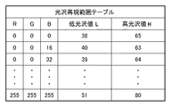
図9のブロック図により実施例2の画像処理装置12の構成例を示す。実施例2の切替信号生成部104は、光沢再現範囲が記録されたテーブル(以下、光沢再現範囲LUT)121を保持する。図10により光沢再現範囲LUT121の一例を示す。
An example of the configuration of the
光沢再現範囲LUT121は、RGB値ごとの低光沢値L、高光沢値Hを示すテーブルである。低光沢値Lは、最小の光沢画像データGl=0のときに再現可能な光沢値であり、低光沢用の画像処理によって画像形成を行った場合に得られる光沢値である。また、高光沢値Hは、最大の光沢画像データGl=255のときに再現可能な光沢値であり、高光沢用の画像処理によって画像形成を行った場合に得られる光沢値であり、予め、画像形成装置13によりテストチャートを作成して測定可能である。
The gloss reproduction range LUT 121 is a table indicating a low gloss value L and a high gloss value H for each RGB value. The low gloss value L is a reproducible gloss value when the minimum gloss image data Gl = 0, and is a gloss value obtained when an image is formed by image processing for low gloss. The high gloss value H is a reproducible gloss value when the maximum gloss image data Gl = 255, and is a gloss value obtained when an image is formed by high gloss image processing. A test chart can be created and measured by the
なお、光沢再現範囲LUT121は、RGB値のすべての組み合わせに対する低光沢値L、高光沢値Hを保持する必要はなく、例えばRGB値を16刻みにした173=4913格子点に対応する低光沢値L、高光沢値Hを保持する。そして、格子点間のRGB値に対応する低光沢値L、高光沢値Hの取得には、四面体補間などの任意の補間方法を用いればよい。 Note that the gloss reproduction range LUT 121 does not need to hold the low gloss value L and the high gloss value H for all combinations of RGB values.For example, low gloss values corresponding to 17 3 = 4913 grid points with 16 RGB values The value L and the high gloss value H are retained. Then, in order to obtain the low gloss value L and the high gloss value H corresponding to the RGB values between the lattice points, any interpolation method such as tetrahedral interpolation may be used.
切替信号生成部104は、色画像データRGBを入力し、光沢再現範囲LUT121を参照して色画像データRGBに対応する光沢値を、ステップS401の処理における低光沢値Lおよび高光沢値Hとして取得する。そして、入力した光沢画像データGlに対応する選択信号GCを生成する。
The switching
色画像データRGBに対して取得される低光沢値をL(RGB)、高光沢値をH(RGB)とすると、切替信号生成部104は、下式により、面積率Vtを算出する(S401)。
Vt = {V - L(RGB)}/{H(RGB) - L(RGB)};
if (Vt < 0) Vt = 0;
if (Vt > 1) Vt = 1;
Vt = Vt×M; …(3)
ここで、Vは光沢画像データGlの画素値、
Mは光沢値Vの最大値(例えば255)。
Assuming that the low gloss value obtained for the color image data RGB is L (RGB) and the high gloss value is H (RGB), the switching
Vt = {V-L (RGB)} / {H (RGB)-L (RGB)};
if (Vt <0) Vt = 0;
if (Vt> 1) Vt = 1;
Vt = Vt × M;… (3)
Here, V is the pixel value of the gloss image data Gl,
M is the maximum value of the gloss value V (for example, 255).
以下、図4に示す実施例1の処理と同様に、切替信号生成部104は、注目画素の面積率Vtと、注目画素に対応する、閾値マトリクスのセルの閾値thの比較を行う(S402)。面積率が閾値を超える(Vt>th)場合は、注目画素に対して高光沢用の画像処理を設定するために切替信号GC=‘1’を設定する(S403)。また、面積率が閾値以下(Vt≦th)の場合は、注目画素に対して低光沢の画像処理を設定するために切替信号GC=‘0’を設定する(S404)。
Hereinafter, similarly to the process of the first embodiment illustrated in FIG. 4, the switching
次に、切替信号生成部104は、全画素について切替信号GCの生成を行ったか否かを判定し(S405)、未了の画素があれば処理をステップS401に戻し、全画素の切替信号GCの生成が終了するまでステップS401からS404の処理を繰り返す。
Next, the switching
このように、再現する色に対応する光沢再現範囲を保持し、光沢再現範囲に応じて光沢画像データGlの光沢値Vを面積率Vtに変換する。その結果、複数の色によって構成される画像においても光沢値を安定に再現して、光沢の滑らかな階調再現が可能になる。 As described above, the gloss reproduction range corresponding to the color to be reproduced is held, and the gloss value V of the gloss image data Gl is converted into the area ratio Vt according to the gloss reproduction range. As a result, a gloss value can be stably reproduced even in an image composed of a plurality of colors, and smooth gradation reproduction of gloss can be performed.
色ごとの光沢再現範囲の取得方法は上記に限らず、ユーザがRGB値に対応する光沢再現範囲を入力してもよい。さらに、ユーザの指定色について、光沢画像データGlを変化させたテストチャートを形成し、光沢写像性を測定することで、ユーザ指定色について光沢再現の制御精度が高い光沢再現範囲LUT121に補正する補正部を備えることもできる。 The method of acquiring the gloss reproduction range for each color is not limited to the above, and the user may input a gloss reproduction range corresponding to the RGB value. Furthermore, a test chart in which the gloss image data Gl is changed for a user-specified color is formed, and gloss clarity is measured, thereby correcting the gloss reproduction range LUT121 having a high gloss reproduction control accuracy for the user-specified color. A unit may be provided.
以下、本発明にかかる実施例3の画像処理装置および画像処理方法を説明する。なお、実施例3において、実施例1、2と略同様の構成については、同一の符号を付して、その詳細な説明を省略する場合がある。 Hereinafter, an image processing apparatus and an image processing method according to the third embodiment of the present invention will be described. In the third embodiment, the same components as those in the first and second embodiments are denoted by the same reference numerals, and detailed description thereof may be omitted.
実施例1、2では、低光沢LUT111と高光沢LUT112が、同一RGB値に対して略同一の色を再現する記録材量値を保持する例を説明した。しかし、画像形成装置13の処理によっては、光沢値が最大になる場合と最小になる場合で色再現範囲が大きく異なることがある。例えば、低光沢では濃色材を多用するために色再現範囲が広く、高光沢では淡色材を多用するために色再現範囲が狭くなることがある。
In the first and second embodiments, an example is described in which the
言い替えれば、同一RGB値に対して低光沢と高光沢で略同一の色再現を行うように色分解LUTを設計すれば、色再現範囲の狭い高光沢の色再現性に合わせた色設計になる。その結果、低光沢において再現可能な色再現範囲の活用が難しくなる場合がある。 In other words, if a color separation LUT is designed to perform almost the same color reproduction at the same RGB value with low gloss and high gloss, the color design will match the color reproduction of high gloss with a narrow color reproduction range . As a result, it may be difficult to utilize a color reproduction range that can be reproduced with low gloss.
実施例3では、入力された色画像データのRGB値に対して画像形成装置13が再現可能な、色値を記録したテーブル(以下、再現色値LUT)を使用する。また、低光沢用の画像処理により、所定の色値に対して画像形成装置13が再現可能な低光沢値、および、高光沢用の画像処理により、所定の色値に対して画像形成装置13が再現可能な高光沢値を記録したテーブル(以下、光沢再現範囲LUT)を保持する。
In the third embodiment, a table (hereinafter, a reproduction color value LUT) that records color values that can be reproduced by the
実施例3では、これらテーブルを参照して色画像データRGBに対応する色値を再現する際の光沢再現範囲を算出し、光沢画像データGlを当該光沢再現範囲の面積率に変換する。その結果、より広い色再現範囲で光沢の滑らかな階調再現が可能になる。 In the third embodiment, the gloss reproduction range when reproducing the color value corresponding to the color image data RGB is calculated with reference to these tables, and the gloss image data Gl is converted into the area ratio of the gloss reproduction range. As a result, it is possible to reproduce glossy smooth gradation in a wider color reproduction range.
図11のブロック図により実施例3の画像処理装置12の構成例を示す。実施例3の切替信号生成部104は、光沢再現範囲LUT122および再現色値LUT123を保持する。図12により光沢再現範囲LUT122および再現色値LUT123の一例を示す。
An example of the configuration of the
図12(b)に示す再現色値LUT123は、色画像データのRGB値(入力信号値)と画像形成装置13が再現可能な出力色値(Lab値)の関係を保持する。図12(a)に示す光沢再現範囲LUT122は、同一RGB値を低光沢と高光沢の画像処理条件で画像形成した場合の色値(Lab)、並びに、低光沢値Lcおよび高光沢値Hcを保持する。
The reproduced
なお、再現色値LUT123は、RGB値のすべての組み合わせに対する色値を保持する必要はなく、例えばRGB値を16刻みにした173=4913格子点に対応する離散的な色値を保持する。格子点間のRGB値に対する色値の取得には、四面体補間などの任意の補間方法を用いればよい。光沢再現範囲LUT122も同様であり、格子点間のLabに対する光沢値の取得には、四面体補間などの任意の補間方法を用いればよい。
Note that the reproduction
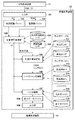
図13のフローチャートにより実施例3の切替信号生成部104の処理を説明する。切替信号生成部104は、注目画素の色画像データRGBを入力し(S1301)、再現色LUT123を参照して色画像データRGBに対応する色値を取得する(S1302)。次に、注目画素の光沢画像データGlを入力し(S1303)、光沢再現範囲LUT122に基づき、注目画素の色値と光沢値Vに対応する光沢値Lと高光沢値Hを取得する(S1304)。そして、光沢値Lおよび光沢値Hに基づいて光沢値Vを面積率Vtに変換する(S1305)。
The processing of the switching
図14は色光沢空間を説明する図であり、明度値L*を省略し、色情報a*、b*および光沢値によって色と光沢の再現範囲を表した模式図である。以下では、色値と光沢値の組み合わせを「色光沢値」と呼ぶ。図14における明度値L*の省略は表記上の都合であり、実際の処理は明度値L*も用いる四次元空間である色光沢空間における処理になる。 FIG. 14 is a diagram for explaining the color gloss space, in which the lightness value L * is omitted and the reproduction range of color and gloss is represented by color information a *, b * and a gloss value. Hereinafter, the combination of the color value and the gloss value is referred to as “color gloss value”. The omission of the lightness value L * in FIG. 14 is a notational convenience, and the actual processing is processing in a color glossy space that is a four-dimensional space that also uses the lightness value L *.
図14において、曲面1401は低光沢用の画像処理による色光沢の再現範囲を表し、曲面1402は高光沢用の画像処理による色光沢の再現範囲を表す。言い替えれば、曲面1401と1402は、光沢再現範囲LUT122が表す色光沢値の再現範囲であり、以下、曲面1401を「低光沢色域」、曲面1402を「高光沢色域」と呼ぶ。図14に示すように、低光沢色域と高光沢色域では、色再現範囲が異なり光沢再現範囲が異なる。
In FIG. 14, a
ステップS1302、S1303で取得した色光沢値は、図14に示す色光沢空間の一点で表される。切替信号生成部104は、取得した色光沢値に近い光沢再現範囲LUT122の格子点を探索する。なお、高光沢色域1402を低光沢色域1401に投影した場合に両者が重なる領域を「共通域」と呼ぶことにする。
The color / gloss values obtained in steps S1302 and S1303 are represented by one point in the color / gloss space shown in FIG. The switching
●色光沢値が共通域内にある場合
点1403のように色光沢値が共通域に存在する場合、点1403から光沢軸に平行に延伸した直線と低光沢色域1401との交点1404、および、高光沢色域1402との交点1405は、点1403と同色度(色情報a*、b*が同値)になる。点1404と点1405の光沢値を、周囲の格子点の光沢値を参照する補間演算によって算出し、点1404の光沢値をL、点1405の光沢値をHとし、実施例1と同様の式(1)(2)により、点1403の光沢値Vを面積率Vtに変換する。
When the color gloss value is in the common range When the color gloss value is in the common range as in the
●色光沢値が共通域外にある場合
一方、点1406のように色光沢値が共通域の外に存在する場合、点1406から光沢軸に平行に延伸した直線と低光沢色域1401との交点1407は存在するが、高光沢色域1402との交点が存在しない。言い替えれば、色値を再現可能な点が高光沢色域1402に存在しない。このような場合、光沢再現範囲LUT122が保持する格子点のすべての組み合わせから、点1406を間に挟む格子点の組み合わせを探索する。そして、当該組み合わせが存在する場合は四次元空間における補間手法を用いて点1406と同色度を再現する光沢値Hと光沢値Lを算出する。
When the color gloss value is outside the common range On the other hand, when the color gloss value is outside the common range like
図14は、点1406を挟む低光沢色域1401の格子点として1401a-1401dが、高光沢色域1402の格子点として1402a-1402dが探索された例を示している。格子点1401a-1401dの四点から光沢値Lを求め、格子点1401a-1401bおよび1402a-1402bの八点から光沢値Hを求める例を示している。算出される光沢値の中で最も高い光沢値をH、算出される光沢値の中で最も低い光沢値をLとして、実施例1と同様の式(1)(2)により、点1406の光沢値Vを面積率Vtに変換する。
FIG. 14 shows an example in which 1401a to 1401d are found as grid points of the low
もし、点1406を間に挟む格子点の組み合わせが存在しない場合は、色光沢値の差が最小になる共通域に点1406をマッピングし、光沢値HとLを取得して、光沢値Vを面積率Vtに変換する。以降の処理は実施例1と同様であり、同一符号を付して、説明を省略する。なお、色光沢値の差とは、色値の差と光沢値の差の合計である。
If there is no combination of grid points sandwiching the
また、実施例3の低光沢LUT111と高光沢LUT112は、色光沢値を入力値として記録材量データ(出力値)が記録されている。記録材料決定部105は、切替信号生成部104から入力される色光沢値に基づき、色分解処理を実行する。
In the
このように、光沢によって色再現範囲が大きく異なる場合も、色再現範囲を有効に活用しながら光沢の滑らかな階調再現を得ることができる。なお、上記では、色についてLab値を用いる例を説明したが、色を表現する色空間は任意である。 As described above, even when the color reproduction range is greatly different depending on the gloss, it is possible to obtain a smooth gradation reproduction of the gloss while effectively utilizing the color reproduction range. In the above description, an example in which Lab values are used for colors has been described, but a color space for expressing colors is arbitrary.
上記では、低光沢において色再現範囲が広く、高光沢において色再現範囲が狭い例を説明した。しかし、低光沢を再現するためにドットの重複率を高くするようなドットパターンを用いる場合、低光沢の色再現範囲が高光沢よりも狭くなる場合でもあり、そのような場合も本実施例を適用可能である。 In the above, an example was described in which the color reproduction range was wide at low gloss and narrow at high gloss. However, when using a dot pattern that increases the dot overlap rate in order to reproduce low gloss, the color reproduction range of low gloss may be narrower than that of high gloss. Applicable.
また、格子点の組み合わせによって色光沢値を挟むことができない場合、色光沢値の差が最小になる共通域にマッピング処理する例を説明したが、マッピング方法はこれに限定されない。例えば、ユーザが指定する優先度に応じて、光沢値の差を最小にするマッピング方法、色値の差を最小にするマッピング方法、あるいは、共通域の境界にマッピングする方法を選択してもよい。 Further, in the case where the color gloss value cannot be sandwiched by the combination of grid points, an example has been described in which mapping processing is performed on a common area where the difference in color gloss value is minimized, but the mapping method is not limited to this. For example, a mapping method that minimizes the difference in gloss value, a mapping method that minimizes the difference in color value, or a method that maps to the boundary of the common area may be selected according to the priority specified by the user. .
[変形例]
実施例1-3において、色画像データと光沢画像データが入力される例を説明した。光沢画像データに代えて例えば距離情報のように印刷物として再現が困難な物理量が入力された場合、当該情報を印刷物上で再現可能な光沢情報に置き換えて画像処理を行ってもよい。
[Modification]
In Embodiment 1-3, an example in which color image data and gloss image data are input has been described. When a physical quantity that is difficult to reproduce as a printed matter, such as distance information, is input instead of the glossy image data, image processing may be performed by replacing the information with glossy information that can be reproduced on the printed matter.
以下では、本発明を適用可能な変形例について説明を行う。なお、変形例において、実施例1-3と略同様の構成については、同一の符号を付して、その詳細な説明を省略する場合がある。 Hereinafter, modified examples to which the present invention can be applied will be described. Note that, in the modified example, the same reference numerals are given to configurations substantially similar to those of the embodiment 1-3, and detailed description thereof may be omitted.
●変形例1
実施例1-3では、色画像データと光沢画像データが入力される例を説明した。しかし、入力データは、色画像データと、色画像データとは対象物を表現する物理量の一部が異なり、階調表現を伴う(連続する階調性を有する)データであればよい。この場合、色画像データが第一のデータとなり、第一のデータが表す色とは異なる物理量の連続階調性を表すデータが第二のデータとなる。実施例1-3の場合、色画像データが第一のデータとなり、光沢画像データが第二のデータとなる。変形例1では、色画像データと鮮鋭性を表す鮮鋭度画像データの組み合わせを入力して、出力画像の鮮鋭度を多階調制御する例を説明する。
-
In the first to third embodiments, an example in which color image data and gloss image data are input has been described. However, the input data may be any data as long as the color image data is different from the color image data in that a part of the physical quantity representing the object is different and the color data is accompanied by a gradation expression (having a continuous gradation characteristic). In this case, the color image data is the first data, and the data representing the continuous tone of a physical quantity different from the color represented by the first data is the second data. In the case of the embodiment 1-3, the color image data is the first data, and the glossy image data is the second data. Modification Example 1 describes an example in which a combination of color image data and sharpness image data representing sharpness is input and the sharpness of an output image is controlled in multiple gradations.
鮮鋭度は、隣接画素との間の輝度差または濃度差が大きい場合に高く、隣接画素との間の輝度差または濃度差が小さい場合に低い。そこで、変形例1では、隣接画素との間の濃度差が維持され易い画像処理条件と、隣接画素との間の濃度差が維持され難い画像処理条件を保持して、画素ごとに画像処理条件を切り替えることで、任意の鮮鋭度を再現する。
The sharpness is high when the luminance difference or the density difference between the adjacent pixels is large, and is low when the luminance difference or the density difference between the adjacent pixels is small. Therefore, in
図15のブロック図により変形例1の画像処理装置の構成例を示す。変形例1の画像処理装置12の入力部101は、色画像データRGBのみを入力し、実施例1の光沢画像バッファ103に代えて鮮鋭度画像生成部130を備える。なお、情報処理装置11において生成された鮮鋭度画像データが入力部101に入力されてもよい。
FIG. 15 is a block diagram showing an example of the configuration of an image processing apparatus according to the first modification. The
鮮鋭度画像生成部130は、色画像バッファ102に格納された色画像データに基づき鮮鋭度画像データを生成する。鮮鋭度画像データの生成方法は、色画像データにおいて、隣接画素の間における画素値の差分を計算する方法を用いる。隣接画素の間の画素値の差分が大きい画素位置において鮮鋭度画像データの値が大きくなり、鮮鋭度が高いことが表され、鮮鋭度画像データは0(非鮮鋭)から255(鮮鋭)の8ビットデータとする。
The sharpness
切替信号生成部104は、鮮鋭度画像データの画素値である鮮鋭度Sを面積率Vtに変換する。面積率Vtは、画像形成装置13によって形成可能な高鮮鋭の鮮鋭値SHを選択する割合を示し、下式によって算出される。
Vt = (S - SL)/(SH - SL);
if (Vt < 0) Vt = 0;
if (Vt > 1) Vt = 1;
Vt = Vt×M; …(4)
ここで、SLは形成可能な低鮮鋭値、
SHは形成可能な高鮮鋭値、
Mは鮮鋭値Sの最大値(例えば255)。
The
Vt = (S-S L ) / (S H -S L );
if (Vt <0) Vt = 0;
if (Vt> 1) Vt = 1;
Vt = Vt × M;… (4)
Here, S L is capable of forming a low sharpness value,
S H is capable of forming a high sharpness value,
M is the maximum value of the sharpness value S (for example, 255).
次に、切替信号生成部104は、注目画素の面積率Vtと、注目画素に対応する、閾値マトリクスのセルの閾値thの比較を行う。面積率が閾値を超える(Vt>th)場合は、注目画素に対して高鮮鋭用の画像処理(最大値用の画像処理)を設定するために切替信号GC=‘1’を設定する。また、面積率が閾値以下(Vt≦th)の場合は、注目画素に対して低鮮鋭用の画像処理(最小値用の画像処理)を設定するために切替信号GC=‘0’を設定する。以上の切替信号GCの生成処理は、実施例1と同様に、全画素について行われる。
Next, the switching
変形例1の画像処理装置12は、低光沢LUT111と高光沢LUT112に代えて色分解処理用に低鮮鋭LUT131と高鮮鋭LUT132を備える。同様に、低光沢MTX113と高光沢MTX114に代えて低鮮鋭MTX133と高鮮鋭MTX134を備え、低光沢マスク115と高光沢マスク116に代えて低鮮鋭マスク135と高鮮鋭マスク136を備える。
The
顔料インクを使用するプリンタにおいては、濃色材に比べて淡色材を多用すると、隣接画素との間の濃度差が小さくなり、鮮鋭度が低下する傾向がある。従って、低鮮鋭LUT131は淡色材を相対的に多用し、高鮮鋭LUT132は濃色材を相対的に多用するように出力値が設定されている。
In a printer using a pigment ink, when a light-colored material is used more than a dark-colored material, the density difference between adjacent pixels becomes smaller, and the sharpness tends to be reduced. Therefore, the output value is set so that the low-
顔料インクを使用するプリンタにおいて、インク滴の着弾位置が近いドット同士や、インク滴の着弾タイミングの差が小さいドット同士における結合は発生し易い。色や階調が異なるドット同士が結合すると、それらドット間の色や階調の変化が鈍り鮮鋭度の低下が発生する。従って、着弾位置が分散されるドット分散型のブルーノイズ特性のディザマトリクスを高鮮鋭MTX133として使用し、着弾位置が小領域に集中するドット集中型のグリーンノイズ特性のディザマトリクスを高鮮鋭MTX134として使用する。 In a printer that uses pigment ink, it is easy for dots that are close to the landing position of an ink droplet or dots that have a small difference in the landing timing of an ink droplet to combine. When dots having different colors and gradations are combined, the change in the color and gradation between the dots becomes dull, resulting in a decrease in sharpness. Therefore, the dither matrix of the dot dispersion type blue noise characteristic in which the impact positions are dispersed is used as the high sharp MTX133, and the dither matrix of the dot concentration type green noise characteristic in which the impact positions are concentrated in a small area is used as the high sharp MTX134. I do.
顔料インクを使用するマルチパス記録方式のプリンタにおいて双方向印刷を行うと、片方向印刷に比べて、往路走査と復路走査でインクの着弾位置のずれが発生し、鮮鋭度が低下する。従って、双方向印刷になるパスマスクを低鮮鋭マスク135、片方向印刷になるパスマスクを高鮮鋭マスク136として使用する。
When bidirectional printing is performed in a multi-pass printing method using a pigment ink, compared with unidirectional printing, a shift in ink landing position occurs in forward scan and backward scan, and the sharpness is reduced. Therefore, a pass mask for bidirectional printing is used as the
このように、色画像データから生成した鮮鋭度画像データに基づき、鮮鋭度変化の滑らかな再現を得ることができる。 Thus, a smooth reproduction of the sharpness change can be obtained based on the sharpness image data generated from the color image data.
上記では、光沢画像データの代わりに鮮鋭度画像データを用いる例を説明したが、データの種類に限定はない。例えば、内部散乱、凹凸、距離などを表すデータでもよい。また、色画像データは必須ではなく、三種類以上のデータを入力してもよい。本発明の本質は、ある特性値(光沢など)の再現値が異なる二種類以上の記録方法が規定される場合に、再現値が異なる二種類以上の画像処理条件によって、特性値の再現値を多階調に再現することにあり、本発明は、任意の特性値に対して適用することができる。 In the above, an example in which the sharpness image data is used instead of the glossy image data has been described, but the type of data is not limited. For example, data representing internal scattering, unevenness, distance, and the like may be used. Further, color image data is not essential, and three or more types of data may be input. The essence of the present invention is that, when two or more types of recording methods having different reproduction values of a certain characteristic value (such as gloss) are defined, the reproduction value of the characteristic value is determined by two or more types of image processing conditions having different reproduction values. The present invention can be applied to any characteristic value because reproduction is performed in multiple gradations.
●変形例2
実施例1-3、変形例1においては、記録材として顔料インクを用いて画像形成するプリンタを例に説明したが、本発明が適用可能な画像形成装置はこれに限らない。例えば、紫外線硬化インク(以下、UV硬化インク)を用いるプリンタでもよい。変形例2では、UV硬化インクを用いて印刷物の凹凸を再現する画像形成装置を説明する。
-
In the first to third embodiments and the first modification, a printer that forms an image using a pigment ink as a recording material has been described as an example. However, the image forming apparatus to which the present invention can be applied is not limited thereto. For example, a printer using ultraviolet curable ink (hereinafter, UV curable ink) may be used. In a second modification, an image forming apparatus that reproduces unevenness of a printed material using a UV curable ink will be described.
図16のブロック図により変形例2の画像処理装置の構成例を示す。変形例2の画像処理装置12の入力部101は、色画像データRGBと凹凸データを入力し、実施例1の光沢画像バッファ103に代えて凹凸データバッファ140を備える。
FIG. 16 is a block diagram showing an example of the configuration of an image processing apparatus according to a second modification. The
凹凸データは、所定領域内の表面粗さに基づいて0(平滑)〜255(粗い)の8ビット画像データとする。画像形成装置13は、上述した色材のほかに、凹凸を形成するための記録材としてUV硬化インクを備える。UV硬化インクは、例えば紫外線硬化樹脂を含む実質的に無色透明の記録材である。UV硬化インクによって記録媒体上に凹凸層を記録し、凹凸層の上(画像面)に色材によって画像を形成する。なお、UV硬化インクには僅かな色や濁りがあっても構わない。
The unevenness data is 8-bit image data from 0 (smooth) to 255 (rough) based on the surface roughness in a predetermined area. The
切替信号生成部104は、凹凸データの画素値である表面粗さAを面積率Vtに変換する。面積率Vtは、画像形成装置13によって形成可能な表面粗さの最高値AHを選択する割合を示し、下式によって算出される。なお、形成可能な表面粗さの最低値AHは0である。
Vt = A/AH;
if (Vt < 0) Vt = 0;
if (Vt > 1) Vt = 1;
Vt = Vt×M; …(5)
ここで、Mは高度Aの最大値(例えば255)。
The
Vt = A / A H ;
if (Vt <0) Vt = 0;
if (Vt> 1) Vt = 1;
Vt = Vt × M;… (5)
Here, M is the maximum value of the altitude A (for example, 255).
次に、切替信号生成部104は、注目画素の面積率Vtと、注目画素に対応する、閾値マトリクスのセルの閾値thの比較を行う。面積率が閾値を超える(Vt>th)場合は、注目画素に対して表面粗さが最大となる粗面用の画像処理(最大値用の画像処理)を設定するために切替信号GC=‘1’を設定する。また、面積率が閾値以下(Vt≦th)の場合は、注目画素に対して表面粗さが最小となる平滑面用の画像処理(最小値用の画像処理)を設定するために切替信号GC=‘0’を設定する。以上の切替信号GCの生成処理は、実施例1と同様に、全画素について行われる。
Next, the switching
変形例2の画像処理装置12は、低光沢LUT111と高光沢LUT112に代えて色分解処理用にUV硬化インクの材量データUV(例えばUV=255)を出力する粗面用LUT141と、材量データUV=0を常に出力する平滑面用LUT142を備える。同様に、低光沢MTX113と高光沢MTX114に代えて粗面MTX143と平滑面MTX144を備え、低光沢マスク115と高光沢マスク116に代えてパスマスク145を備える。
The
パスマスク145を参照するパス分解部107は、例えば第一のパスにおいて、切替信号GCが粗面用の画像処理を示す場合はUV硬化インクの記録信号に従い、対象となる領域のみにUV硬化インクを記録する駆動データを生成する。例えば、領域中を面積率50%の千鳥格子となるようにUV効果インクを記録する駆動データを生成する。また、切替信号GCが平滑面用の画像処理を示す場合はUV硬化インクの記録信号に関わらずUV硬化インク用の駆動データを生成しない。これにより、切替信号GCによって粗面用の画像処理を示す領域は、UV硬化インクが記録される領域と記録されない領域が混在し、記録媒体上に凹凸が形成される。残りのパスにおいて、パス分解部107は、色材の記録信号に従い駆動データを生成する。
For example, in the first pass, if the switching signal GC indicates image processing for a rough surface, the
なお、上記はUV硬化インクを記録するか否かによって記録媒体上に凹凸を形成する例を述べたが上記の一例に限定されない。実施例1で説明したように、ディザマトリクスやパスマスクを切り替え、上記のUV硬化インクに加え、色材による凹凸を形成してもよい。 In the above description, the example in which the unevenness is formed on the recording medium depending on whether or not to record the UV curable ink has been described. As described in the first embodiment, the dither matrix and the pass mask may be switched to form the unevenness due to the coloring material in addition to the UV curable ink.
例えば、色材のディザマトリクスとして、着弾位置が小領域に集中するドット集中型のブルーノイズ特性のディザマトリクスを粗面MTX143として使用する。一方、着弾位置が分散されるドット分散型のグリーンノイズ特性のディザマトリクスを平滑面MTX144として使用する。 For example, as a color material dither matrix, a dot concentration type blue noise characteristic dither matrix in which landing positions are concentrated in a small area is used as the rough surface MTX143. On the other hand, a dot-dispersion type green noise characteristic dither matrix in which landing positions are dispersed is used as the smooth surface MTX144.
また、色材のパスマスクとして、着弾時間差が大きいパスマスクを粗面用のパスマスクに使用し、着弾時間差が小さいパスマスクを平滑面用のパスマスクとして使用する。 As a color material pass mask, a pass mask having a large landing time difference is used as a pass mask for a rough surface, and a pass mask having a small landing time difference is used as a pass mask for a smooth surface.
このように、凹凸データに基づき、凹凸変化の滑らかな再現を得ることができる。 In this manner, a smooth reproduction of the change in the unevenness can be obtained based on the unevenness data.
本発明はインクジェット方式以外の記録方式にも適用可能であり、静電潜像に粉体もしくは液体の色材を転写する電子写真方式や、昇華方式にも適用可能である。また、紫外線硬化インクを用いて凹凸を再現する記録装置や、樹脂もしくは粉体を積み重ねて固めていくことで立体物を成形する3Dプリンタなどにも同様に適用可能である。 The present invention can be applied to a recording method other than the ink jet method, and can also be applied to an electrophotographic method in which a powder or liquid coloring material is transferred to an electrostatic latent image, and a sublimation method. Further, the present invention can be similarly applied to a recording device that reproduces unevenness using an ultraviolet curable ink, a 3D printer that forms a three-dimensional object by stacking and solidifying resin or powder, and the like.
また、本発明は記録媒体上に色材を用いて画像を形成する画像形成装置以外にも、ディスプレイやプロジェクタのように入力の画像データに対応した点灯パターンによって画像を表示する画像表示装置にも同様に適用可能である。画像表示装置の場合、記録材量決定部とドットパターン決定部ではなく、入力の色信号を画像表示部で表示する色信号(色成分信号)に変換する色変換部において、第二のデータに応じて切り替わる複数の画像処理部を備える。 In addition, the present invention is applicable not only to an image forming apparatus that forms an image using a color material on a recording medium, but also to an image display apparatus that displays an image by a lighting pattern corresponding to input image data, such as a display or a projector. It is equally applicable. In the case of an image display device, the color conversion unit that converts an input color signal into a color signal (color component signal) to be displayed on the image display unit is used instead of the recording material amount determination unit and the dot pattern determination unit. It has a plurality of image processing units that are switched according to.
例えば、第二のデータとして鮮鋭度を用いる場合、色変換部において、フィルタ係数が異なる暈しフィルタを複数保持する。切替信号GCに応じて、低鮮鋭度の場合には暈し強度が強いフィルタを用いた画像処理を行う。また、高鮮鋭度の場合には暈し強度が弱いフィルタを用いた処理を行う。このように、鮮鋭度画像データに基づき、鮮鋭度変化の滑らかな再現を画像表示装置においても得ることができる。 For example, when using the sharpness as the second data, the color conversion unit holds a plurality of blur filters having different filter coefficients. In the case of low sharpness, image processing using a filter having a strong blurring intensity is performed according to the switching signal GC. In the case of high sharpness, processing using a filter having a low blurring intensity is performed. In this manner, a smooth reproduction of the change in sharpness can be obtained in the image display device based on the sharpness image data.
[その他の実施例]
本発明は、上述の実施形態の一以上の機能を実現するプログラムを、ネットワーク又は記憶媒体を介してシステム又は装置に供給し、そのシステム又は装置のコンピュータにおける一以上のプロセッサがプログラムを読み出し実行する処理でも実現可能である。また、一以上の機能を実現する回路(例えば、ASIC)によっても実現可能である。
[Other Examples]
The present invention supplies a program realizing one or more functions of the above-described embodiments to a system or an apparatus via a network or a storage medium, and one or more processors in a computer of the system or the apparatus read and execute the program. Processing can also be realized. It can also be realized by a circuit (for example, an ASIC) that realizes one or more functions.
101 … 入力部、104 … 切替信号生成部、105 … 記録材量決定部 101: input unit, 104: switching signal generation unit, 105: recording material amount determination unit
Claims (21)
前記第一のデータに基づいて、前記画像を記録媒体上に形成するための記録材の記録量を決定する第一の決定手段と、
前記決定された記録量に対する前記第二のデータに応じたハーフトーン処理によって、前記記録媒体上を複数回記録走査して前記画像を形成する際の前記記録材のドット配置を決定する第二の決定手段と、
を有することを特徴とする画像処理装置。 Input means for inputting first data representing the color of the image, and second data relating to the gloss of the image,
Based on the first data, a first determination unit that determines the recording amount of a recording material for forming the image on a recording medium,
By halftone processing according to the second data to the recording amount of pre Symbol determined, first determine the dot arrangement of the recording material when forming the image on said recording medium a plurality of times recording scan two Means for determining
An image processing apparatus comprising:
ことを特徴とする請求項1に記載された画像処理装置。 The second determining unit switches between the first halftone process and a second halftone process different from the first halftone process based on the second data , thereby obtaining the dot data. The image processing apparatus according to claim 1, wherein the arrangement is determined.
前記第2のハーフトーン処理は、ドットを一部の領域に集中させるためのハーフトーン処理である
ことを特徴とする請求項2に記載された画像処理装置。 The first halftone process is a halftone process for distributing and arranging dots,
The image processing apparatus according to claim 2, wherein the second halftone processing is a halftone processing for concentrating dots in a partial area.
ことを特徴とする請求項2又は請求項3に記載された画像処理装置。 The image processing apparatus according to claim 2, wherein the first halftone process and the second halftone process use different dither matrices. 5.
前記第2のハーフトーン処理は、グリーンノイズ特性を有するディザマトリクスを用いたハーフトーン処理である
ことを特徴とする請求項2から請求項4の何れか一項に記載された画像処理装置。 The first halftone process is a halftone process using a dither matrix having a blue noise characteristic,
The image processing apparatus according to claim 2, wherein the second halftone processing is a halftone processing using a dither matrix having a green noise characteristic.
前記第二の決定手段は、前記信号と前記決定された記録量とに基づいて、前記ドット配置を決定する
ことを特徴とする請求項2から請求項5の何れか一項に記載された画像処理装置。 Based on said second data, further comprising a generation means for generating a signal for switching the processing,
The image according to claim 2, wherein the second determination unit determines the dot arrangement based on the signal and the determined recording amount. Processing equipment.
ことを特徴とする請求項6に記載された画像処理装置。 The generating means calculates a ratio of a difference between the minimum gloss and the gloss represented by the second data to a difference between a maximum gloss and a minimum gloss that can be reproduced by the image forming apparatus that forms the image, and The image processing apparatus according to claim 6, wherein the signal is generated by comparing the signal with a predetermined threshold.
ことを特徴とする請求項7に記載された画像処理装置。 The image processing apparatus according to claim 7, wherein the threshold is a threshold included in a threshold matrix having a blue noise characteristic.
ことを特徴とする請求項8に記載された画像処理装置。 At least one of a threshold, a screen angle, and a screen ruling is different between the threshold matrix when the generating unit generates the signal and the dither matrix used when the second determining unit determines the dot arrangement. The image processing apparatus according to claim 8, wherein:
ことを特徴とする請求項7から請求項9の何れか一項に記載された画像処理装置。 The image processing apparatus according to any one of claims 7 to 9, wherein the maximum gloss and the minimum gloss are acquired for each color represented by the first data.
前記第一のデータが同一の場合、前記低光沢を表現するための処理に応じて形成された前記画像の光沢と、前記高光沢を表現するための処理に応じて形成された前記画像の光沢と、の差が最大になる
ことを特徴とする請求項6から請求項10の何れか一項に記載された画像処理装置。 The signal is a signal for switching the processing to either a process for expressing low gloss or a process for expressing high gloss,
When the first data is the same, the gloss of the image formed according to the process for expressing the low gloss and the gloss of the image formed according to the process for expressing the high gloss The image processing apparatus according to any one of claims 6 to 10, wherein the difference between (i) and (i) is maximized.
ことを特徴とする請求項1から請求項11の何れか一項に記載された画像処理装置。 The first determination means further includes a first color separation process for determining a recording amount of the recording material so as to record a large amount of dark color material based on the second data; The recording amount is determined by switching between a second color separation process that determines the recording amount of the recording material so as to record more light color material than the recording amount determined by the process. The image processing device according to claim 1.
ことを特徴とする請求項12に記載された画像処理装置。 In the first color separation process, the recording amount of the recording material is determined with reference to a look-up table in which the recording amount of the dark color material increases, and in the second color separation process, the recording amount of the light color material is determined. 13. The image processing apparatus according to claim 12, wherein the recording amount of the recording material is determined with reference to a look-up table in which the number of recording materials increases.
ことを特徴とする請求項12又は請求項13に記載された画像処理装置。 The first determining means outputs recording amount data representing a recording amount of a clear material when the second data indicates low gloss and the first data indicates white. An image processing apparatus according to claim 12.
ことを特徴とする請求項1から請求項14の何れか一項に記載された画像処理装置。 The second determining unit is configured to perform a first pass separation process for dispersing dot printing in a plurality of print scans, and a dot arrangement of the printing material for each print scan determined by the first pass separation process. 15. The dot arrangement for each print scan is determined by switching between a second pass separation process that concentrates dot printing on a small number of print scans. An image processing apparatus according to claim 1.
ことを特徴とする請求項1から請求項15の何れか一項に記載された画像処理装置。 The image processing apparatus according to claim 1, further comprising a control unit configured to control an image forming apparatus for forming the image on the recording medium.
前記第一のデータに基づいて、前記画像を記録媒体上に形成するための記録材の記録量を決定する第一の決定手段と、
前記決定された記録量に対する前記第二のデータに応じたハーフトーン処理によって、前記記録媒体上を複数回記録走査して前記画像を形成する際の前記記録材のドット配置を決定する第二の決定手段と、
を有することを特徴とする画像処理装置。 Input means for inputting first data representing the color of the image, and second data representing the sharpness of the image,
Based on the first data, a first determination unit that determines the recording amount of a recording material for forming the image on a recording medium,
By halftone processing according to the second data to the recording amount of pre Symbol determined, first determine the dot arrangement of the recording material when forming the image on said recording medium a plurality of times recording scan two Means for determining
An image processing apparatus comprising:
ことを特徴とする請求項17に記載された画像処理装置。The image processing apparatus according to claim 17, wherein:
前記第一のデータに基づいて、前記画像を記録媒体上に形成するための記録材の記録量を決定し、
前記決定された記録量に対する前記第二のデータに応じたハーフトーン処理によって、前記記録媒体上を複数回記録走査して前記画像を形成する際の前記記録材のドット配置を決定する
ことを特徴とする画像処理方法。 First data representing the color of the image and second data relating to the gloss of the image are input,
Based on the first data, determine the recording amount of a recording material for forming the image on a recording medium,
By halftone processing according to the second data to the recording amount of pre Symbol determined, determining the dot arrangement of the recording material when the upper the recording medium a plurality of times recording scan to form the image Characteristic image processing method.
前記第一のデータに基づいて、前記画像を記録媒体上に形成するための記録材の記録量を決定し、
前記決定された記録量に対する前記第二のデータに応じたハーフトーン処理によって、前記記録媒体上を複数回記録走査して前記画像を形成する際の前記記録材のドット配置を決定する
ことを特徴とする画像処理方法。 First data representing the color of the image and second data representing the sharpness of the image,
Based on the first data, determine the recording amount of a recording material for forming the image on a recording medium,
By halftone processing according to the second data to the recording amount of pre Symbol determined, determining the dot arrangement of the recording material when the upper the recording medium a plurality of times recording scan to form the image Characteristic image processing method.
Priority Applications (5)
| Application Number | Priority Date | Filing Date | Title |
|---|---|---|---|
| JP2015182227A JP6660127B2 (en) | 2015-09-15 | 2015-09-15 | Image processing apparatus and method, and image forming apparatus |
| EP16845881.8A EP3349989A4 (en) | 2015-09-15 | 2016-08-15 | Image processing apparatus, method thereof, and image forming apparatus |
| CN201680053402.5A CN108025561B (en) | 2015-09-15 | 2016-08-15 | Image processing equipment and its method, image forming apparatus and medium |
| US15/757,030 US10511740B2 (en) | 2015-09-15 | 2016-08-15 | Image processing apparatus, method thereof, and image forming apparatus that determine a dot arrangement of printing material by halftone processing |
| PCT/JP2016/003741 WO2017047003A1 (en) | 2015-09-15 | 2016-08-15 | Image processing apparatus, method thereof, and image forming apparatus |
Applications Claiming Priority (1)
| Application Number | Priority Date | Filing Date | Title |
|---|---|---|---|
| JP2015182227A JP6660127B2 (en) | 2015-09-15 | 2015-09-15 | Image processing apparatus and method, and image forming apparatus |
Publications (3)
| Publication Number | Publication Date |
|---|---|
| JP2017056603A JP2017056603A (en) | 2017-03-23 |
| JP2017056603A5 JP2017056603A5 (en) | 2018-11-22 |
| JP6660127B2 true JP6660127B2 (en) | 2020-03-04 |
Family
ID=58288409
Family Applications (1)
| Application Number | Title | Priority Date | Filing Date |
|---|---|---|---|
| JP2015182227A Active JP6660127B2 (en) | 2015-09-15 | 2015-09-15 | Image processing apparatus and method, and image forming apparatus |
Country Status (5)
| Country | Link |
|---|---|
| US (1) | US10511740B2 (en) |
| EP (1) | EP3349989A4 (en) |
| JP (1) | JP6660127B2 (en) |
| CN (1) | CN108025561B (en) |
| WO (1) | WO2017047003A1 (en) |
Families Citing this family (5)
| Publication number | Priority date | Publication date | Assignee | Title |
|---|---|---|---|---|
| CN108600771B (en) * | 2018-05-15 | 2019-10-25 | 东北农业大学 | Recorded broadcast workstation system and operating method |
| CN109683833B (en) * | 2018-12-19 | 2022-04-15 | 森大(深圳)技术有限公司 | Method, system, device and storage medium for enhancing image to be printed |
| JP7378262B2 (en) | 2019-10-11 | 2023-11-13 | スリーエム イノベイティブ プロパティズ カンパニー | Inkjet printing method and inkjet printing device |
| CN111754504B (en) * | 2020-07-01 | 2024-03-19 | 华能国际电力股份有限公司大连电厂 | Chemical mixed bed layering detection method based on machine vision |
| US20230256766A1 (en) * | 2022-02-17 | 2023-08-17 | Riso Kagaku Corporation | Printing apparatus and method |
Family Cites Families (17)
| Publication number | Priority date | Publication date | Assignee | Title |
|---|---|---|---|---|
| US7121660B2 (en) * | 2002-09-30 | 2006-10-17 | Canon Kabushiki Kaisha | Print producing method and print producing apparatus |
| JP4770488B2 (en) * | 2006-01-31 | 2011-09-14 | コニカミノルタホールディングス株式会社 | Inkjet printer |
| JP2008213271A (en) | 2007-03-02 | 2008-09-18 | Canon Inc | Ink-jet recording method |
| US8383189B2 (en) * | 2008-04-21 | 2013-02-26 | Xerox Corporation | Selectable gloss coating system |
| JP5202150B2 (en) * | 2008-07-16 | 2013-06-05 | キヤノン株式会社 | Image processing apparatus and method |
| JP2010120185A (en) | 2008-11-17 | 2010-06-03 | Canon Inc | Image processing apparatus and image processing method |
| JP5620702B2 (en) * | 2010-04-02 | 2014-11-05 | キヤノン株式会社 | Image processing apparatus, image processing method, and program |
| JP5698469B2 (en) * | 2010-06-08 | 2015-04-08 | キヤノン株式会社 | Information processing apparatus and information processing method |
| JP5733928B2 (en) | 2010-08-11 | 2015-06-10 | キヤノン株式会社 | Image recording apparatus, image recording method, and program |
| JP5729950B2 (en) * | 2010-08-31 | 2015-06-03 | キヤノン株式会社 | Image processing apparatus and image processing method |
| JP5696521B2 (en) | 2011-02-18 | 2015-04-08 | セイコーエプソン株式会社 | Recording device and color sample table |
| JP5988679B2 (en) * | 2012-05-08 | 2016-09-07 | キヤノン株式会社 | Image processing apparatus, ink jet recording apparatus, and image processing method |
| JP5943698B2 (en) * | 2012-05-08 | 2016-07-05 | キヤノン株式会社 | Image processing device |
| US9168757B2 (en) * | 2013-08-22 | 2015-10-27 | Canon Kabushiki Kaisha | Image processing apparatus and image processing method |
| JP6149614B2 (en) | 2013-08-30 | 2017-06-21 | セイコーエプソン株式会社 | RECORDING DATA GENERATION DEVICE, PROGRAM, RECORDING DATA GENERATION METHOD, AND RECORDING DEVICE |
| JP6167766B2 (en) * | 2013-08-30 | 2017-07-26 | セイコーエプソン株式会社 | Inkjet recording method |
| JP2016012122A (en) * | 2014-06-03 | 2016-01-21 | キヤノン株式会社 | Photomask, method for manufacturing optical element array, and optical element array |
-
2015
- 2015-09-15 JP JP2015182227A patent/JP6660127B2/en active Active
-
2016
- 2016-08-15 WO PCT/JP2016/003741 patent/WO2017047003A1/en unknown
- 2016-08-15 CN CN201680053402.5A patent/CN108025561B/en not_active Expired - Fee Related
- 2016-08-15 US US15/757,030 patent/US10511740B2/en not_active Expired - Fee Related
- 2016-08-15 EP EP16845881.8A patent/EP3349989A4/en not_active Withdrawn
Also Published As
| Publication number | Publication date |
|---|---|
| WO2017047003A1 (en) | 2017-03-23 |
| JP2017056603A (en) | 2017-03-23 |
| EP3349989A4 (en) | 2019-05-01 |
| CN108025561B (en) | 2019-08-30 |
| EP3349989A1 (en) | 2018-07-25 |
| US10511740B2 (en) | 2019-12-17 |
| US20190068832A1 (en) | 2019-02-28 |
| CN108025561A (en) | 2018-05-11 |
Similar Documents
| Publication | Publication Date | Title |
|---|---|---|
| JP6660127B2 (en) | Image processing apparatus and method, and image forming apparatus | |
| JP6609141B2 (en) | Image processing apparatus and method, and image forming apparatus | |
| JP5014475B2 (en) | Image processing apparatus and image processing method | |
| US20050280848A1 (en) | Color conversion method, color conversion device, printing control device, and program recording medium | |
| US8651609B2 (en) | Color processing device for determining colorless material recording amount data | |
| JP6581698B2 (en) | Image processing apparatus and method | |
| JP5634154B2 (en) | Image processing apparatus and image processing method | |
| US9832349B2 (en) | Image processing apparatus and image processing method | |
| JP2004187301A (en) | Calibration of digital printer using cost function | |
| JPH11198452A (en) | Image correction method | |
| JP2006231624A (en) | Generation of lookup table for printing using variable density ink | |
| JP2023052886A (en) | Image processing device, image processing method, and program | |
| US9851651B2 (en) | Image processing apparatus and image processing method to control the gloss of an image to be printed | |
| JP5606150B2 (en) | Image processing apparatus and image processing method | |
| JP2012081638A (en) | Apparatus and method for processing image | |
| JP6860307B2 (en) | Image processing device and its method, and image forming device | |
| US11936835B2 (en) | Image processing apparatus, image processing method, and storage medium which reduce a color difference and a frequency difference between two images | |
| JP2003283856A5 (en) | ||
| JP5769465B2 (en) | Color conversion apparatus, color conversion method and program | |
| JP5641881B2 (en) | Image processing apparatus and image processing method | |
| JP2004314432A (en) | Method of printing by making tone jump inconspicuous | |
| JP2017007288A (en) | Image processing apparatus and image processing method, and program |
Legal Events
| Date | Code | Title | Description |
|---|---|---|---|
| A521 | Request for written amendment filed |
Free format text: JAPANESE INTERMEDIATE CODE: A523 Effective date: 20180907 |
|
| A621 | Written request for application examination |
Free format text: JAPANESE INTERMEDIATE CODE: A621 Effective date: 20180907 |
|
| A521 | Request for written amendment filed |
Free format text: JAPANESE INTERMEDIATE CODE: A523 Effective date: 20181011 |
|
| A131 | Notification of reasons for refusal |
Free format text: JAPANESE INTERMEDIATE CODE: A131 Effective date: 20190823 |
|
| A521 | Request for written amendment filed |
Free format text: JAPANESE INTERMEDIATE CODE: A523 Effective date: 20191015 |
|
| TRDD | Decision of grant or rejection written | ||
| A01 | Written decision to grant a patent or to grant a registration (utility model) |
Free format text: JAPANESE INTERMEDIATE CODE: A01 Effective date: 20200110 |
|
| A61 | First payment of annual fees (during grant procedure) |
Free format text: JAPANESE INTERMEDIATE CODE: A61 Effective date: 20200207 |
|
| R151 | Written notification of patent or utility model registration |
Ref document number: 6660127 Country of ref document: JP Free format text: JAPANESE INTERMEDIATE CODE: R151 |