JP6659678B2 - Supply cable, driver configuration with wireless control function, and control method - Google Patents
Supply cable, driver configuration with wireless control function, and control method Download PDFInfo
- Publication number
- JP6659678B2 JP6659678B2 JP2017520531A JP2017520531A JP6659678B2 JP 6659678 B2 JP6659678 B2 JP 6659678B2 JP 2017520531 A JP2017520531 A JP 2017520531A JP 2017520531 A JP2017520531 A JP 2017520531A JP 6659678 B2 JP6659678 B2 JP 6659678B2
- Authority
- JP
- Japan
- Prior art keywords
- housing
- antenna
- connection head
- driver
- configuration
- Prior art date
- Legal status (The legal status is an assumption and is not a legal conclusion. Google has not performed a legal analysis and makes no representation as to the accuracy of the status listed.)
- Active
Links
- 238000000034 method Methods 0.000 title claims description 9
- 239000000463 material Substances 0.000 claims description 7
- 238000005286 illumination Methods 0.000 claims description 3
- 230000006854 communication Effects 0.000 description 12
- 238000004891 communication Methods 0.000 description 12
- 230000006870 function Effects 0.000 description 6
- 230000005540 biological transmission Effects 0.000 description 5
- 238000004519 manufacturing process Methods 0.000 description 5
- 238000007789 sealing Methods 0.000 description 4
- 230000001681 protective effect Effects 0.000 description 3
- 230000006978 adaptation Effects 0.000 description 2
- 230000007175 bidirectional communication Effects 0.000 description 2
- 230000009286 beneficial effect Effects 0.000 description 1
- 230000000903 blocking effect Effects 0.000 description 1
- 230000001419 dependent effect Effects 0.000 description 1
- 238000005516 engineering process Methods 0.000 description 1
- 238000009434 installation Methods 0.000 description 1
- 239000002184 metal Substances 0.000 description 1
- 238000000465 moulding Methods 0.000 description 1
- 230000002093 peripheral effect Effects 0.000 description 1
- 230000004044 response Effects 0.000 description 1
- 230000005236 sound signal Effects 0.000 description 1
- 238000004078 waterproofing Methods 0.000 description 1
Images


Classifications
-
- H—ELECTRICITY
- H01—ELECTRIC ELEMENTS
- H01Q—ANTENNAS, i.e. RADIO AERIALS
- H01Q1/00—Details of, or arrangements associated with, antennas
- H01Q1/44—Details of, or arrangements associated with, antennas using equipment having another main function to serve additionally as an antenna, e.g. means for giving an antenna an aesthetic aspect
- H01Q1/46—Electric supply lines or communication lines
-
- H—ELECTRICITY
- H01—ELECTRIC ELEMENTS
- H01Q—ANTENNAS, i.e. RADIO AERIALS
- H01Q1/00—Details of, or arrangements associated with, antennas
- H01Q1/12—Supports; Mounting means
- H01Q1/22—Supports; Mounting means by structural association with other equipment or articles
-
- H—ELECTRICITY
- H01—ELECTRIC ELEMENTS
- H01Q—ANTENNAS, i.e. RADIO AERIALS
- H01Q7/00—Loop antennas with a substantially uniform current distribution around the loop and having a directional radiation pattern in a plane perpendicular to the plane of the loop
-
- H—ELECTRICITY
- H05—ELECTRIC TECHNIQUES NOT OTHERWISE PROVIDED FOR
- H05B—ELECTRIC HEATING; ELECTRIC LIGHT SOURCES NOT OTHERWISE PROVIDED FOR; CIRCUIT ARRANGEMENTS FOR ELECTRIC LIGHT SOURCES, IN GENERAL
- H05B47/00—Circuit arrangements for operating light sources in general, i.e. where the type of light source is not relevant
- H05B47/10—Controlling the light source
- H05B47/175—Controlling the light source by remote control
- H05B47/19—Controlling the light source by remote control via wireless transmission
-
- H—ELECTRICITY
- H01—ELECTRIC ELEMENTS
- H01R—ELECTRICALLY-CONDUCTIVE CONNECTIONS; STRUCTURAL ASSOCIATIONS OF A PLURALITY OF MUTUALLY-INSULATED ELECTRICAL CONNECTING ELEMENTS; COUPLING DEVICES; CURRENT COLLECTORS
- H01R9/00—Structural associations of a plurality of mutually-insulated electrical connecting elements, e.g. terminal strips or terminal blocks; Terminals or binding posts mounted upon a base or in a case; Bases therefor
- H01R9/22—Bases, e.g. strip, block, panel
- H01R9/24—Terminal blocks
- H01R9/2475—Means facilitating correct wiring, e.g. marking plates, identification tags
Landscapes
- Engineering & Computer Science (AREA)
- Computer Networks & Wireless Communication (AREA)
- Near-Field Transmission Systems (AREA)
- Support Of Aerials (AREA)
- Circuit Arrangement For Electric Light Sources In General (AREA)
Description
本発明は、無線コマンドを送信及び/又は受信するためのアンテナを組み込んだデバイスに関する。本発明は、とりわけ、デバイスが、例えば防水のため囲われることを要しハウジングを持ち、斯かるハウジングはアンテナ信号をブロックするであろう、アプリケーションに関する。 The present invention relates to a device incorporating an antenna for transmitting and / or receiving wireless commands. The invention relates, inter alia, to applications where the device requires a housing to be enclosed, for example for waterproofing, and has a housing, which housing will block antenna signals.
興味深い一つのアプリケーションは、無線でコンフィギュラブルなLEDドライバである。 One interesting application is a wireless and configurable LED driver.
LED技術の迅速な適応により、エンドアプリケーションの要求を満たすようオンデマンドでコンフィギュアされ得るプログラム可能な電子ドライバの必要性が増している。これは、照明器具製造者が、最小在庫管理単位数を減らすことにより、より良く在庫を管理する手助けとなる。一例として、LEDドライバは、電流レベルのある範囲及び調光オプション、例えば、0乃至10V、DALIをサポートするよう設計され得る。 The rapid adaptation of LED technology has increased the need for programmable electronic drivers that can be configured on demand to meet end application requirements. This helps lighting fixture manufacturers better manage inventory by reducing the number of minimum inventory units. As an example, an LED driver may be designed to support a range of current levels and dimming options, eg, 0-10V, DALI.
この場合、照明器具製造者は、製造プロセスの終わりに特定の電流レベルにLEDドライバをプログラムすることができる。斯かるプログラム可能なLEDドライバは、市販されており、RS−232又はDALI等の有線通信インタフェースを用いて通常コンフィギュアされる。Wifi又はZigbee等の無線ソリューションも存在するが、高コストに起因して限定される。 In this case, the luminaire manufacturer can program the LED driver to a specific current level at the end of the manufacturing process. Such programmable LED drivers are commercially available and are usually configured using a wired communication interface such as RS-232 or DALI. Wireless solutions such as Wifi or Zigbee also exist, but are limited due to high cost.
無線通信機能を与えるため、専用のアンテナが、無線通信システムに要求される。IP65又はより高い高保護等級のアプリケーションのため、アンテナは、LEDドライバのエンクロージャと共に、IP等級を満足しなければならない。これは、とりわけ、LEDドライバの保護エンクロージャの外部にアンテナを置くことが望ましいので、難しい問題となる。 To provide a wireless communication function, a dedicated antenna is required for the wireless communication system. For IP65 or higher high protection grade applications, the antenna, along with the LED driver enclosure, must meet IP rating. This is a difficult problem, especially since it is desirable to place the antenna outside the protective enclosure of the LED driver.
同じことが、デバイスがエンクロージャの内部に設けられ、関連するアンテナを要する無線レシーバ(及び/又はトランスミッタ)回路を含み、該アンテナは該エンクロージャの外部にあることを必要とするアプリケーションにも当てはまる。 The same applies to applications where the device is provided inside the enclosure and includes a radio receiver (and / or transmitter) circuit that requires an associated antenna, which antenna needs to be outside the enclosure.
斯くして、斯かるアプリケーションのためのアンテナ構成の一般的必要性がある。 Thus, there is a general need for antenna configurations for such applications.
米国特許第US 7 417 592号公報に開示されるように、ケーブル、例えば、携帯電話と共に用いるイヤホンケーブルに無線アンテナを組み込むことが知られている。この目的は、長いUHF及びVHFアンテナのための空間を見つけることにある。 It is known to incorporate a wireless antenna into a cable, such as an earphone cable for use with a mobile phone, as disclosed in US Pat. No. 7,417,592. The purpose is to find room for long UHF and VHF antennas.
欧州特許出願公開第EP2629363A1号公報は、アンテナが組み込まれた電気ケーブルのハーネスを開示する。 EP-A-2629363 A1 discloses a harness for an electric cable with an integrated antenna.
アンテナがハウジングにより影響を受けない/ブロックされないようにハウジングとアンテナを統合することを可能にするソリューション/ストラクチャを持つことは有利である。また、アンテナが統合される場合でもハウジングの保護等級を維持することが有利である。 It would be advantageous to have a solution / structure that allows the housing and antenna to be integrated such that the antenna is not affected / blocked by the housing. It is also advantageous to maintain the degree of protection of the housing even when the antenna is integrated.
少なくとも上述の課題に対処するため、本発明が、特許請求の範囲により規定される。 The present invention is defined by the claims, at least to address the above-mentioned problems.
本発明の第1の態様によれば、ハウジング内のデバイスへの供給ケーブルと共に用いる接続ヘッド(connection head)であって、
当該接続ヘッドは、
前記デバイスの前記ハウジングの外部に設ける第1の端部、
前記デバイスの前記ハウジングの内部に設ける第2の端部、及び
少なくとも1つのコイル、及びフィードラインの対を持つ閉ループアンテナ、
を有し、
前記フィードラインは、前記第1の端部から前記第2の端部に延在し、前記少なくとも1つのコイルは、前記第1の端部に位置する、接続ヘッドが提供される。
According to a first aspect of the invention, there is provided a connection head for use with a supply cable to a device in a housing, the connection head comprising:
The connection head is
A first end provided outside the housing of the device;
A second end provided inside the housing of the device; and a closed loop antenna having at least one coil and a pair of feed lines;
Has,
A connection head is provided, wherein the feed line extends from the first end to the second end and the at least one coil is located at the first end.
この構成は、アンテナの保護を与えるためケーブル用の接続ヘッドを用いる。このようにして、ハウジングへの保護される開口の数が、最小限に保たれる。例えば、供給ケーブルをハウジングの内部に案内するために用いられる接続ヘッドは、所望の密封要求(sealing requirement)(例えば、IP65)を既に満たしているであろう。結果として、同一の密封要求が、付加的な保護シース又はハウジングの開口を要せずに当該アンテナ構成により満たされる。ハウジングの外部にアンテナを設けることが望ましい場合に、当該接続ヘッドは、外側ハウジングを持つ任意のデバイスに適用されることができる。また、アンテナは、ハウジングによりブロックされず、斯くして無線通信性能が維持される。 This configuration uses a connection head for the cable to provide protection for the antenna. In this way, the number of protected openings to the housing is kept to a minimum. For example, the connection head used to guide the supply cable into the interior of the housing will already meet the desired sealing requirements (eg, IP65). As a result, the same sealing requirements are met by the antenna arrangement without the need for an additional protective sheath or housing opening. If it is desirable to provide the antenna outside the housing, the connection head can be applied to any device with an outer housing. Also, the antenna is not blocked by the housing, thus maintaining wireless communication performance.
前記少なくとも1つのコイルは、当該接続ヘッドの長軸の周りに方向付けられ(oriented)、前記供給ケーブルは、パワーを伝送するための、前記閉ループアンテナとは異なるパワーラインを有してもよい。 The at least one coil may be oriented around a long axis of the connection head, and the supply cable may have a different power line for transmitting power than the closed loop antenna.
これは、パワーライン及びアンテナ両方のコンパクトな構成を提供し、容易に組み立てられることもできる。 This provides a compact configuration of both the power line and the antenna and can also be easily assembled.
前記アンテナは、例えば、6乃至10個のコイルを有してもよく、各コイルは、8乃至12mmの径を持ってもよい。一つの特定の例は、径が10mmの8個のコイルを用いることができる。一例として、アンテナは、13.56MHzのRF周波数向けに設計される。これは、NFC(Near Field Communications:近距離無線通信)プロトコルに用いられる周波数の一例である。コイルは、例えば、4.3μHのインダクタンスを持ってもよい。 The antenna may have, for example, 6 to 10 coils, each coil having a diameter of 8 to 12 mm. One particular example may use eight coils with a diameter of 10 mm. As an example, the antenna is designed for an RF frequency of 13.56 MHz. This is an example of a frequency used for an NFC (Near Field Communications: Near Field Communication) protocol. The coil may for example have an inductance of 4.3 μH.
さらに、当該接続ヘッドは、無線をブロックしない材料(radio non-blocking material)から作られる。斯くして、アンテナは、接続ヘッドによりブロックされず、無線通信性能が維持されることができる。 Furthermore, the connection head is made from a radio non-blocking material. Thus, the antenna is not blocked by the connection head, and the wireless communication performance can be maintained.
接続ヘッド及びハウジングの簡単でしっかりとした係合のため、当該接続ヘッドは、前記ハウジングの開口と係合する環状凹部を含み、前記アンテナの前記少なくとも1つのコイルは、前記環状凹部の外部側(exterior side)における当該接続ヘッドの前記第1の端部内に収容され、(前記ハウジングの内部に設けるための)前記第2の端部は、前記環状凹部の内部側(interior side)にある。この実施形態は、接続ヘッドをハウジングに固定するための固定ストラクチャ(fixing structure)を提供し、斯かる固定ストラクチャは、アンテナを収容し、保護するためにも適用可能である。 For simple and secure engagement of the connection head and the housing, the connection head includes an annular recess which engages with the opening of the housing, and the at least one coil of the antenna is connected to the outside of the annular recess ( Housed within the first end of the connection head on the exterior side, the second end (for installation inside the housing) is on the interior side of the annular recess. This embodiment provides a fixing structure for fixing the connecting head to the housing, which fixing structure is also applicable for housing and protecting the antenna.
拡大された接続ヘッドは、凹部及びハウジングの開口の間に水密封止を与えるようにゴム材料であってもよい。拡大されたヘッド内にアンテナコイルを嵌合させることにより、空間が上手く利用され、アンテナは、ハウジング内部のレシーバに極めて接近する。例えば、レシーバ及びアンテナ間の距離は20乃至30mmであり得る。 The enlarged connection head may be a rubber material to provide a watertight seal between the recess and the opening in the housing. By fitting the antenna coil into the enlarged head, space is better utilized and the antenna is very close to the receiver inside the housing. For example, the distance between the receiver and the antenna may be between 20 and 30 mm.
前記デバイスは、前記閉ループアンテナを介して無線制御信号を受信するレシーバ回路であってもよく、前記閉ループアンテナは、前記レシーバ回路にパワーを供給するよう構成されるNFCアンテナであってもよい。これは、NFC通信が、前記デバイスを制御する又はコンフィギュアするために用いられ得、これはまた、供給パワーラインをアクティブにする必要なくコンフィギュレーションに必要とされるパワーを供給できることを意味する。このようにして、コンフィギュレーションが、前記デバイスに主電源が供給される前に、生産工程の最終段階で実行されることができる。 The device may be a receiver circuit that receives a radio control signal via the closed loop antenna, and the closed loop antenna may be an NFC antenna configured to supply power to the receiver circuit. This means that NFC communication can be used to control or configure the device, which can also supply the power required for configuration without having to activate the supply power line. In this way, configuration can be performed at the end of the production process, before main power is applied to the device.
一実施形態において、当該接続ヘッドは、前記供給ケーブルのアウターシースを囲むためのものである。代替的に、当該接続ヘッドは、前記供給ケーブルのアウターシースと一体である。これら2つの実施形態は、個別コンポーネントとして供給ケーブルと別個であるか又は単一コンポーネントとして供給ケーブルと一体であるかという、接続ヘッドの代替ストラクチャを提供する。 In one embodiment, the connection head is for surrounding the outer sheath of the supply cable. Alternatively, the connection head is integral with the outer sheath of the supply cable. These two embodiments provide an alternative structure of the connection head, either separate from the supply cable as a separate component or integral with the supply cable as a single component.
本発明の一例は、照明構成(lighting arrangement)を駆動するドライバ構成(drive arrangement)であって、
ハウジング、
上述した接続ヘッド、
前記ハウジングの外から前記接続ヘッドを介して前記ハウジングに入る、パワーを供給するための供給ケーブル、
前記ハウジング内のレシーバ回路であって、無線制御信号を受信するため前記フィードラインの対を介して前記アンテナに結合される、レシーバ回路、及び
前記ハウジング内のドライバ回路であって、前記供給ケーブルからパワーを得て、該得たパワーを用いて前記照明構成を駆動するドライバ回路、
を有するドライバ構成であり、
前記ドライバ回路は、前記レシーバ回路に結合され、前記ドライバ回路は、前記アンテナが受信し、前記レシーバ回路によりフォワードされる前記無線制御信号に基づいてコンフィギュラブルである、ドライバ構成を提供する。
One example of the present invention is a driver arrangement for driving a lighting arrangement,
housing,
The connection head described above,
A supply cable for supplying power, which enters the housing from outside the housing via the connection head;
A receiver circuit in the housing, the receiver circuit coupled to the antenna via the pair of feed lines for receiving a radio control signal, and a driver circuit in the housing, the receiver circuit comprising: A driver circuit that obtains power and drives the lighting configuration using the obtained power;
Is a driver configuration having
The driver circuit is coupled to the receiver circuit, the driver circuit providing a driver configuration that is configurable based on the wireless control signal received by the antenna and forwarded by the receiver circuit.
この構成は、アンテナの保護を提供するためドライバ構成へのケーブル接続ヘッドを用いる。接続ヘッドは、例えば、ドライバ構成を用いて照明構成にパワーを供給するためのパワーラインが通過できるよう構成される。 This configuration uses a cable connection head to the driver configuration to provide protection for the antenna. The connection head is configured, for example, to allow passage of a power line for supplying power to the lighting arrangement using a driver arrangement.
前記接続ヘッドは、前記ハウジング内への前記供給ケーブルの防水経路(watertight passage)を提供するよう構成される。この単一の防水経路は、アンテナ及び供給ケーブルがハウジングの開口を通過することを可能にする。 The connection head is configured to provide a watertight passage of the supply cable into the housing. This single waterproof path allows the antenna and feed cable to pass through the housing opening.
パワリングケーブル(powering cable)が、前記照明構成へパワーを伝送するため当該ドライバ構成及び前記照明構成を接続するために設けられ、前記パワリングケーブルは、前記ハウジングを通る防水経路を持ってもよい。この場合、ハウジングは、供給ケーブル用のインレット通路(inlet passageway)及び照明構成に至る駆動ケーブル(drive cable)用のアウトレット通路(outlet passageway)を備える、ドライバ構成のためのものである。 A powering cable is provided for connecting the driver configuration and the lighting configuration to transfer power to the lighting configuration, and the powering cable may have a waterproof path through the housing. . In this case, the housing is for a driver arrangement with an inlet passageway for the supply cable and an outlet passageway for the drive cable leading to the lighting arrangement.
当該ドライバ構成は、例えば、IP65の要求を満たしてもよい。 The driver configuration may, for example, satisfy the requirements of IP65.
一実施形態において、前記アンテナは、NFCアンテナを有し、前記レシーバ回路は、NFC集積回路を有し、前記NFC集積回路は、前記NFCアンテナによりパワーが供給されるよう構成され、前記レシーバ回路は、前記ドライバ回路が前記照明構成を駆動し始めるとディスエーブルされるよう構成される。このようにして、無線機能は、製造工程/リコンフィギュレーション(re-configuration)工程の一部としてのみ用いられる。しかしながら、無線機能は、その代わりに、当該デバイスのユーザ機能に貢献してもよい。 In one embodiment, the antenna has an NFC antenna, the receiver circuit has an NFC integrated circuit, the NFC integrated circuit is configured to be powered by the NFC antenna, and the receiver circuit has , Is configured to be disabled when the driver circuit starts driving the lighting configuration. In this way, the wireless function is used only as part of the manufacturing / re-configuration process. However, the wireless function may instead contribute to the user function of the device.
NFC通信は、例えば、遠隔制御デバイスからドライバに制御コマンド又はコンフィギュレーションコマンドを送るために用いられる。これらは、ドライバ構成がエンドユーザにより用いられる前に用いられることができ、最終生産段階の一部であり得る。コンフィギュレーションは、アンテナ越しのパワー伝送を用いて実施され得るため、デバイスにパワーが供給されることを必要としない。 NFC communication is used, for example, to send control or configuration commands from a remote control device to a driver. These can be used before the driver configuration is used by the end user and can be part of the final production stage. The configuration may be performed using power transmission over the antenna, so that the device does not need to be powered.
前記ドライバ回路は、例えば、前記無線制御信号に応じて電流出力レベルを設定する及び/又は電流調光レベルを設定するようコンフィギュラブルであってもよい。 The driver circuit may be configurable, for example, to set a current output level and / or to set a current dimming level in response to the wireless control signal.
前記レシーバ回路はさらに、無線制御信号を送信するトランシーバ回路として構成されてもよい。この場合、前記ドライバ回路は、前記トランシーバ回路及び前記閉ループアンテナを介して無線制御信号を送信するようコンフィギュラブルである。 The receiver circuit may be further configured as a transceiver circuit for transmitting a wireless control signal. In this case, the driver circuit is configurable to transmit a wireless control signal via the transceiver circuit and the closed loop antenna.
これは、ドライバ回路及び外部コントローラ間の双方向通信を可能にする。 This allows for bidirectional communication between the driver circuit and the external controller.
他の態様による例は、
上述したドライバ構成、及び
前記ドライバ構成により駆動される照明構成、
を有する照明システムを提供する。
Examples according to other aspects include:
A driver configuration as described above, and an illumination configuration driven by the driver configuration,
An illumination system having:
他の態様による例は、ハウジング内に収容されるデバイスを制御する方法であって、
無線制御信号を供給するステップ、
前記デバイスの前記ハウジングの外部に設けられるアンテナ及び前記デバイスの前記ハウジングの内部に設けられるレシーバ回路を用いて前記無線制御信号を受信するステップ、及び
前記無線制御信号に基づいて前記デバイスを制御する又はコンフィギュアするステップ、
を有し、
前記アンテナは、少なくとも1つのコイル及びフィードラインの対を持つ閉ループアンテナを有し、前記フィードラインは、前記ハウジングの内部から前記ハウジングの外部に且つ前記供給ケーブルのアウターシース内を前記デバイスまで延在し、前記少なくとも1つのコイルは、前記ハウジングの外部で、前記デバイスへパワーを供給するための供給ケーブルと共に用いる接続ヘッド内に位置する、方法を提供する。
An example according to another aspect is a method of controlling a device contained within a housing, the method comprising:
Providing a wireless control signal;
Receiving the wireless control signal using an antenna provided outside the housing of the device and a receiver circuit provided inside the housing of the device; and controlling the device based on the wireless control signal or Steps to configure,
Has,
The antenna comprises a closed loop antenna having at least one coil and feedline pair, wherein the feedline extends from inside the housing to outside the housing and within the outer sheath of the supply cable to the device. And providing the method wherein the at least one coil is located outside of the housing and in a connection head for use with a supply cable for supplying power to the device.
この方法は、一般に、ハウジングの外部にアンテナを設けることが望ましい、ハウジング内のデバイスを制御することに適用する。アンテナは、供給ケーブルシース(supply cable sheath)内に設けられる。 This method generally applies to controlling devices in the housing where it is desirable to provide the antenna outside the housing. The antenna is provided in a supply cable sheath.
前記デバイスは、前記閉ループアンテナを介して無線制御信号を受信するレシーバ回路を有し、前記閉ループアンテナは、前記レシーバ回路にパワーを供給するよう構成されるNFCアンテナであってもよい。この場合、前記デバイスは、例えば、前記照明構成を駆動するドライバ構成を有し、前記デバイスを制御するステップは、前記無線制御信号に基づいて前記ドライバ構成をコンフィギュアするステップを有する。 The device may include a receiver circuit that receives a wireless control signal via the closed loop antenna, and the closed loop antenna may be an NFC antenna configured to supply power to the receiver circuit. In this case, the device has, for example, a driver configuration for driving the lighting configuration, and controlling the device includes configuring the driver configuration based on the wireless control signal.
この場合、コンフィギュアされたドライバ構成は、該コンフィギュアされたドライバ構成を用いて照明構成を駆動するために用いられることができる。 In this case, the configured driver configuration can be used to drive a lighting configuration using the configured driver configuration.
斯くして、当該方法は、照明用のドライバ構成に適用されることができる。前記ドライバ構成をコンフィギュアするステップは、電流出力レベルを設定する及び/又は電流調光機能(current dimming capability)を設定するステップを有してもよい。 Thus, the method can be applied to a driver configuration for lighting. Configuring the driver configuration may include setting a current output level and / or setting a current dimming capability.
上述した及びその他言及されていない効果及び利点は、図面を参照して以下詳述される本発明の実施形態を研究することにより当業者に理解されるであろう。 The above and other advantages and advantages not mentioned will become apparent to those skilled in the art from a study of the embodiments of the invention, which are described in detail below with reference to the drawings.
本発明の例が、添付の図面を参照して、より詳細に述べられる。
本発明は、ハウジング内のデバイスへパワーを供給するための供給ケーブルを提供する。第1の部分は、デバイスのハウジングの外部に設けるためのものであり、アウターシースを持つ。第2の部分は、デバイスのハウジングの内部に設けるためのものである。閉ループアンテナが、少なくとも1つのコイル、及びフィードラインの対を持ち、フィードラインは、第1の部分のアウターシース内を第2の部分に延在し、少なくとも1つのコイルが、第1の部分のアウターシース内に位置する。供給ケーブルのアウターシースは、アンテナの保護を与え、アンテナがハウジングの外部に設けられることを可能にする。 The present invention provides a supply cable for supplying power to a device in a housing. The first part is for being provided outside the housing of the device and has an outer sheath. The second part is for being provided inside the housing of the device. A closed loop antenna has a pair of at least one coil and a feed line, the feed line extending within the outer sheath of the first portion to the second portion, wherein the at least one coil is connected to the first portion of the first portion. Located in the outer sheath. The outer sheath of the supply cable provides protection for the antenna and allows the antenna to be provided outside the housing.
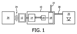
図1は、本発明の一例によるアンテナ構成を用いるために修正され得る照明構成を示す。照明構成は、とりわけドライバの製造の終わりにドライバ構成を設定するため、又はユーザにより用いられた/配備された(deploy)後ドライバをリコンフィギュアするため、LEDドライバと通信するためのNFCプロトコルを用いる。 FIG. 1 shows a lighting configuration that can be modified to use an antenna configuration according to one example of the present invention. The lighting configuration uses the NFC protocol to communicate with the LED driver, especially to set the driver configuration at the end of driver manufacturing or to reconfigure the driver after use / deployment by the user. .
LEDドライバは、主回路が内部に収容される外側ハウジング10を持つ。NFCアンテナは、ハウジング10の外部にあり、(レシーバ回路又はトランシーバ回路であってもよい)NFC集積回路及びメモリに接続する。集積回路及びメモリは、ユニット14として一緒に示されている。パワー出力段18を制御するマイクロコントローラ16へのデータ及びパワー伝送がある。パワー出力段18及びマイクロコントローラ16は、一緒にドライバ回路の役割を果たす。ドライバ回路は、LED構成(LED arrangement)の形態の出力負荷20を制御する。
The LED driver has an
駆動回路は、入力主電源ケーブル22からパワーを受ける。
The drive circuit receives power from the input
ドライバ回路のコンフィギュレーションは、ホストデバイス26とのNFCインタフェース24を用いて確立されることができる。ホストデバイス26は、携帯電話又は他のコンピュータデバイスを含んでもよい。出力ケーブル28は、ドライバ回路からLED構成20にパワーを伝送する。
The configuration of the driver circuit can be established using the
NFCインタフェースは、例えば、13.56MHzの周波数における、ISO/IEC 16593プロトコルを用いる、データ伝送、及びパワー伝送のためであってもよい。無論、他の無線送信プロトコル及び周波数が用いられてもよい。 The NFC interface may be for data transmission and power transmission using the ISO / IEC 16593 protocol at a frequency of 13.56 MHz, for example. Of course, other wireless transmission protocols and frequencies may be used.
これは、LEDドライバが、主電源パワーがアクティブでなくてもコンフィギュアされ得ることを意味する。ドライバに最終的にパワーが供給されると、コンフィギュレーション情報が、例えば電流設定レベル又は調光オプションを取出すため、メモリから取出されることができる。こうして、ドライバはコンフィギュアされ、NFCインタフェースは、LEDドライバの通常の使用時には何の役割も果たさないようにディスエーブルされてもよい。 This means that the LED driver can be configured without main power being active. When the driver is finally powered, configuration information can be retrieved from memory, for example, to retrieve current set levels or dimming options. Thus, the driver may be configured and the NFC interface may be disabled so that it does not play any role during normal use of the LED driver.
図1は、主ハウジング10の外部にアンテナ12を示す。これは、電磁遮蔽を減らすために有益である。
FIG. 1 shows an
本発明のこれらの実施形態は、ハウジング10が、屋外で用いられ得るような保護等級のレベルを要する場合にとりわけ興味深い。この場合、外部コンポーネント及び内部コンポーネント間の各接続が、ハウジング壁を通過するのに適したコネクタを必要とする。
These embodiments of the invention are of particular interest where the
本発明のこの実施形態は、とりわけ、アンテナフィードラインのため及びパワー供給ケーブル22のためハウジングの単一の開口を用いる。
This embodiment of the invention uses a single opening in the housing for the antenna feed line and for the
図2は、ハウジング10の内部にパワーを供給するための、この目的に適う供給ケーブルを示す。
FIG. 2 shows a supply cable suitable for this purpose for supplying power inside the
ケーブル30は、ハウジング10の外部に設ける第1の部分32を持ち、第1の部分32は、アウターシース34を持つ。第2の部分36は、ハウジング10の内部に設けるためのものである。閉ループアンテナが、少なくとも1つのコイル、及びフィードラインの対38を持つ。フィードラインは、第1の部分32のアウターシース内を第2の部分36に延在し(すなわち、ハウジングの外部から内部に入り)、少なくとも1つのコイルは、第1の部分32のアウターシース内に位置する。
The
この構成は、アンテナの保護を与えるためアウターシース34を用いる。ハウジングの開口を通るケーブルの案内(routing)は、例えば、IP65等の所望の密封要求を満たすであろう。結果として、同一の密封要求が、付加的な保護シース又はハウジングの開口を要せずに当該アンテナ構成により満たされる。
This configuration uses an
供給ケーブルは、ハウジング10の開口と係合する環状凹部42を含む拡大された接続ヘッド40を持つ。この接続ヘッドは、“アウターシース内”と定義されるコンポーネントが、拡大された接続ヘッド40内のコンポーネントを含むように、ケーブルのアウターシース34を囲むと解されてもよい。アンテナの少なくとも1つのコイルは、環状凹部42の外部側における拡大された接続ヘッド40の第1の端部内に収容される。この場合、ケーブルの第2の端部36は、環状凹部42の内部側にある拡大された接続ヘッド40の第2の端部を含む。
The supply cable has an
図3は、ハウジング10の開口を通過する供給ケーブルを示す。ハウジングは、例えば、屋外の表面に取付けるための金属ボックスである。
FIG. 3 shows a supply cable passing through an opening in the
図4は、アンテナコイル50を示す透視図で供給ケーブルを示す。アンテナ12は、供給ケーブル30の長軸の周りに方向付けられる一連のコイル50を持ち、供給ケーブルは、パワーを伝送するための、閉ループアンテナとは異なるパワーライン52を有する。拡大された接続ヘッド40は、凹部42の外部側に第1の部分41を持ち、凹部42の内部側に第2の部分43を持つ。
FIG. 4 shows the supply cable in a perspective view showing the
図5は、より明確にアンテナ構成を示す。 FIG. 5 shows the antenna configuration more clearly.
アンテナは、例えば、各々8乃至12mmの径を持つ、6乃至10個のコイルを有してもよい(図5では10個示されている)。一つの特定の例は、径が10mmの8個のコイルを用いることができる。一例として、アンテナは、13.56MHzのRF周波数向けに設計される。コイルは、例えば、4.3μHのインダクタンスを持ってもよい。 The antenna may, for example, have 6 to 10 coils, each having a diameter of 8 to 12 mm (10 are shown in FIG. 5). One particular example may use eight coils with a diameter of 10 mm. As an example, the antenna is designed for an RF frequency of 13.56 MHz. The coil may for example have an inductance of 4.3 μH.
拡大された接続ヘッド40は、凹部42及びハウジングの開口の間に水密封止を与えるようにゴム材料であってもよい。拡大されたヘッド内にアンテナコイルを嵌合させることにより、空間が上手く利用され、アンテナは、ハウジング内部のレシーバに極めて接近する。例えば、レシーバ及びアンテナ間の距離は20乃至30mmであり得る。
The
図6は、断面図でケーブルを示し、断面図の面の後ろに1つのパワー供給ケーブル52及び1つのアンテナフィード38を示す。アウターシース34は、拡大されたヘッド40と一体にすることができ、これらは、供給ケーブル52及びアンテナの周りに設けられる単一成形品として形成されることができる。この場合、拡大されたヘッドの材料は、ケーブルシースの材料と同じである。しかしながら、これに代えて、異なる材料であってもよい。
FIG. 6 shows the cables in cross section, with one
当該ケーブルは、図1に示されるアンテナ及びパワー供給への別個の外部接続を置き換えるために用いられることができるが、図1の照明システムの他の全てのフィーチャは適用されることができる。 The cable can be used to replace the separate external connection to the antenna and power supply shown in FIG. 1, but all other features of the lighting system of FIG. 1 can be applied.
斯くして、ハウジング10、ハウジング10の外部からハウジング10の内部に入る供給ケーブル30、及びフィードラインの対38を介してアンテナに結合される、ハウジング10内のレシーバ回路14を有する、照明構成を駆動するドライバ構成が提供される。供給ケーブル22からパワーを得て、該得たパワーを用いて照明構成20を駆動するドライバ回路16、18もハウジング10内にある。別個のパワリングケーブル28が、照明構成20へパワーを伝送するためドライバ構成及び照明構成20を接続する。これは、ハウジングを通る他の防水経路を持つ。
Thus, a lighting arrangement comprising the
レシーバ回路14はさらに、無線制御信号を送信するトランシーバ回路としても構成されてもよい。この場合、ドライバ回路16、18はさらに、トランシーバ回路及び閉ループアンテナを介して無線制御信号を送信するようコンフィギュラブルである。
The
これは、ドライバ回路及び外部コントローラ間の双方向通信を可能にする。 This allows for bidirectional communication between the driver circuit and the external controller.
上述したように、アンテナは、コンフィギュレーション機能のためのパワーを供給することができる。NFC集積回路及びメモリは、パワーソースとしての役割を果たすホストデバイス26との無線NFCリンク越しに受動的に給電されるコンポーネントであってもよい。
As mentioned above, the antenna can provide power for the configuration function. The NFC integrated circuit and memory may be components that are passively powered over a wireless NFC link with a
本発明は、照明システムに限定されない。類似のNFC制御又はコンフィギュレーションは、交通網で用いられる支払端末、電子財布及び他の携帯電子デバイスを含む、種々のアプリケーションに適用されることができる。 The invention is not limited to lighting systems. Similar NFC controls or configurations can be applied to various applications, including payment terminals, electronic wallets and other portable electronic devices used in transportation networks.
上述の特定の例において、NFC通信リンクは、コンフィギュレーションのためにしか用いられていない。しかしながら、他のアプリケーションにおいて、NFC無線通信は、ユーザが、NFCリンクを用いてハウジング内のデバイスとインタフェースできるように、デバイスの通常機能の一部として用いられてもよい。 In the specific example described above, the NFC communication link is used only for configuration. However, in other applications, NFC wireless communication may be used as part of the normal functionality of the device so that a user can interface with the device in the housing using an NFC link.
本発明はまた、特定のNFCプロトコルに限定されない。実際には、適切なアンテナが、供給ケーブルのコイルの取り得る寸法の範囲に基づいて設計され得ることを条件として、任意の無線通信規格が用いられることができる。 The invention is also not limited to a particular NFC protocol. In practice, any wireless communication standard can be used, provided that a suitable antenna can be designed based on the range of possible dimensions of the coil of the supply cable.
上述したように、例えば米国特許第US 7 417 592号公報に開示されるように、携帯電話と共に用いるイヤホンケーブルに無線アンテナを組み込むことが知られている。本発明の実施形態とこの既知の組み込まれた無線アンテナには顕著な違いがある。 As described above, it is known to incorporate a wireless antenna into an earphone cable used with a mobile phone, as disclosed, for example, in US Pat. No. 7,417,592. There are significant differences between embodiments of the present invention and this known embedded wireless antenna.
先ず、本発明の実施形態においては、供給ケーブルは、ハウジング内にパワーを供給するためのものである。イヤホンの場合、イヤホンケーブルは、音声信号を伝送するためのものである。 First, in the embodiment of the present invention, the supply cable is for supplying power into the housing. In the case of an earphone, the earphone cable is for transmitting an audio signal.
アンテナを供給ケーブル内に置くことにより、ドライバハウジングのエンクロージャの高保護等級能力を維持しつつも、ドライバハウジングのエンクロージャによる無線遮蔽が回避される。イヤホンの場合、対処されるべき課題は、通常非常に長いUHF無線アンテナ及びVHF無線アンテナのための十分な空間が無いということである。スマートフォンのエンクロージャは、通常無線信号をブロックしないので(さもなくば、セルアンテナもブロックされる)、ハウジングによる遮蔽の問題は発生しない。 Placing the antenna in the supply cable avoids radio shielding by the driver housing enclosure while maintaining the high degree of protection capability of the driver housing enclosure. In the case of earphones, the problem to be addressed is that there is usually not enough space for very long UHF and VHF radio antennas. Smartphone enclosures usually do not block wireless signals (otherwise cell antennas are also blocked), so there is no housing shielding problem.
さらに、iPhone(登録商標)シリーズ等のNFC機能を含む現在のスマートフォンでは、ハウジングの外ではなく、背面板下等のスマートフォンハウジング内にもNFCアンテナを置くことが慣例である。 Furthermore, in current smartphones that include an NFC function such as the iPhone (registered trademark) series, it is customary to place the NFC antenna not only outside the housing but also inside the smartphone housing, such as below the back plate.
周辺回路についての結果としての違いもある。本発明の実施形態において、NFC回路は、ドライバをオンにする必要がない。なぜなら、NFCアンテナ、関連するNFC集積回路及びメモリは、ドライバにより給電されず、外部のホストNFCトランシーバにより給電されるからである。イヤホンの場合、スマートフォンにおけるVHF及びUHF無線用の受信及び検知回路は、アンテナから無線信号を受信するためスマートフォンによりターンオンされる必要がある。斯くして、イヤホンの場合に用いられる回路は、適応なく上述した実施形態において用いられ得ない。 There are also resultant differences for peripheral circuits. In embodiments of the present invention, the NFC circuit does not need to turn on the driver. This is because the NFC antenna, the associated NFC integrated circuit and the memory are not powered by the driver, but are powered by an external host NFC transceiver. In the case of earphones, the receiving and detecting circuits for VHF and UHF radio in the smartphone need to be turned on by the smartphone to receive the radio signal from the antenna. Thus, the circuits used in the case of earphones cannot be used without adaptation in the embodiments described above.
開示された実施形態に対する他のバリエーションが、図面、開示及び添付の特許請求の範囲の研究から、当業者によって理解され、実施され得る。請求項において、"有する"という用語は他の要素又はステップを除外するものではなく、単数表記は複数を除外するものではない。特定の手段が相互に異なる従属請求項に記載されるという単なる事実は、これらの手段の組み合わせが有効に用いられ得ないことを示すものではない。請求項の如何なる参照符号も、本発明の範囲を制限するものと見なされるべきでない。
Other variations to the disclosed embodiments can be understood and effected by those skilled in the art from a study of the drawings, the disclosure, and the appended claims. In the claims, the term "comprising" does not exclude other elements or steps, and the singular does not exclude a plurality. The mere fact that certain measures are recited in mutually different dependent claims does not indicate that a combination of these measures cannot be used to advantage. Any reference signs in the claims shall not be construed as limiting the scope of the invention.
Claims (14)
ハウジング、
接続ヘッドであって、デバイスの前記ハウジングの外部に設ける第1の端部、
前記デバイスの前記ハウジングの内部に設ける第2の端部、及び
少なくとも1つのコイル、及びフィードラインの対を持つ閉ループアンテナ、
を有し、
前記フィードラインは、前記第1の端部から前記第2の端部に延在し、前記少なくとも1つのコイルは、前記第1の端部に位置する、接続ヘッド、
前記ハウジングの外から前記接続ヘッドを介して前記ハウジングに入る、パワーを供給するための供給ケーブル、
前記ハウジング内のレシーバ回路であって、無線制御信号を受信するため前記フィードラインの対を介して前記アンテナに結合される、レシーバ回路、及び
前記ハウジング内のドライバ回路であって、前記供給ケーブルからパワーを得て、該得たパワーを用いて前記照明構成を駆動するドライバ回路、
を有するドライバ構成であり、
前記ドライバ回路は、前記レシーバ回路に結合され、前記ドライバ回路は、前記アンテナが受信し、前記レシーバ回路によりフォワードされる前記無線制御信号に基づいてコンフィギュラブルである、ドライバ構成。 A driver configuration for driving a lighting configuration,
housing,
A connection head, a first end provided outside the housing of the device;
A second end provided inside the housing of the device; and a closed loop antenna having at least one coil and a pair of feed lines;
Has,
A connection head extending from the first end to the second end, wherein the at least one coil is located at the first end;
A supply cable for supplying power, which enters the housing from outside the housing via the connection head;
A receiver circuit in the housing, the receiver circuit coupled to the antenna via the pair of feed lines for receiving a radio control signal, and a driver circuit in the housing, the receiver circuit comprising: A driver circuit that obtains power and drives the lighting configuration using the obtained power;
Is a driver configuration having
The driver configuration, wherein the driver circuit is coupled to the receiver circuit, wherein the driver circuit is configurable based on the wireless control signal received by the antenna and forwarded by the receiver circuit.
前記アンテナの前記少なくとも1つのコイルは、前記環状凹部の外部側における前記接続ヘッドの前記第1の端部内に収容され、前記接続ヘッドの前記第2の端部は、前記環状凹部の内部側にあり、
前記アンテナは、前記供給ケーブル及び前記ハウジングとは別個且つ外部にあるホストデバイスと通信するよう構成され、
前記供給ケーブルは、単一の着脱できないケーブルであり、前記接続ヘッドは、前記ケーブルが該接続ヘッドを介して前記ハウジングに入るのを可能にするよう構成される、請求項1に記載のドライバ構成。 The connection head has an annular recess that engages an opening in the housing;
The at least one coil of the antenna is housed in the first end of the connection head on the outside of the annular recess, and the second end of the connection head is on the inside of the annular recess. Yes,
The antenna is configured to communicate with a host device that is separate and external to the supply cable and the housing;
The driver configuration according to claim 1, wherein the supply cable is a single non-detachable cable, and the connection head is configured to allow the cable to enter the housing via the connection head. .
前記レシーバ回路は、無線制御信号を送信するトランシーバ回路としても構成され、
前記ドライバ回路は、前記トランシーバ回路及び前記閉ループアンテナを介して無線制御信号を送信するようコンフィギュラブルである、請求項1乃至10の何れか一項に記載のドライバ構成。 The driver circuit is configurable to set an output level and / or set a dimming level according to the wireless control signal,
The receiver circuit is also configured as a transceiver circuit that transmits a wireless control signal,
The driver configuration according to claim 1, wherein the driver circuit is configurable to transmit a wireless control signal via the transceiver circuit and the closed loop antenna.
前記ドライバ構成により駆動される照明構成、
を有する照明システム。 A driver configuration according to claim 1, and an illumination configuration driven by the driver configuration.
Lighting system having a.
当該方法は、
無線制御信号を供給するステップ、
前記デバイスの前記ハウジングの外部に設けられるアンテナ及び前記デバイスの前記ハウジングの内部に設けられるレシーバ回路を用いて前記無線制御信号を受信するステップ、及び
前記無線制御信号に基づいて前記デバイスを制御する又はコンフィギュアするステップ、
を有し、
前記アンテナは、少なくとも1つのコイル及びフィードラインの対を持つ閉ループアンテナを有し、前記フィードラインは、前記ハウジングの内部から前記ハウジングの外部に延在し、前記少なくとも1つのコイルは、前記ハウジングの外部で、前記デバイスへパワーを供給するための供給ケーブルと共に用いる接続ヘッド内に位置し、
前記デバイスは、前記閉ループアンテナを介して無線制御信号を受信するレシーバ回路を有し、前記閉ループアンテナは、前記レシーバ回路にパワーを供給するよう構成されるNFCアンテナであり、
前記デバイスは、照明構成を駆動するドライバ構成を有し、
前記デバイスを制御するステップは、前記無線制御信号に基づいて前記ドライバ構成をコンフィギュアするステップ、を有する、方法。 A method for controlling a device housed in a housing, comprising:
The method is
Providing a wireless control signal;
Receiving the wireless control signal using an antenna provided outside the housing of the device and a receiver circuit provided inside the housing of the device; and controlling the device based on the wireless control signal or Steps to configure,
Has,
The antenna comprises a closed loop antenna having at least one coil and feed line pair, wherein the feed line extends from inside the housing to outside the housing, and wherein the at least one coil is provided on the housing. Externally located in a connection head for use with a supply cable for supplying power to said device;
The device has a receiver circuit for receiving a radio control signal via the closed loop antenna, wherein the closed loop antenna is an NFC antenna configured to supply power to the receiver circuit;
The device has a driver arrangement for driving the lighting configuration,
Controlling the device, comprising configuring the driver configuration based on the wireless control signal.
当該接続ヘッドは、
前記デバイスの前記ハウジングの外部に設ける第1の端部、
前記デバイスの前記ハウジングの内部に設ける第2の端部、及び
少なくとも1つのコイル、及びフィードラインの対を持つ閉ループアンテナ、
を有し、
前記フィードラインは、前記第1の端部から前記第2の端部に延在し、前記少なくとも1つのコイルは、前記第1の端部に位置し、
前記アンテナは、前記供給ケーブル及び前記ハウジングとは別個且つ外部にあるホストデバイスと通信するよう構成され、
当該接続ヘッドは、前記ハウジングの開口と係合する環状凹部を有し、
前記アンテナの前記少なくとも1つのコイルは、前記環状凹部の外部側における当該接続ヘッドの前記第1の端部内に収容され、前記接続ヘッドの前記第2の端部は、前記環状凹部の内部側にあり、
当該接続ヘッドは、前記供給ケーブルが該接続ヘッドを介して前記ハウジングに入るのを可能にするよう構成される、接続ヘッド。 A connection head for use with a supply cable to a device in a housing,
The connection head is
A first end provided outside the housing of the device;
A second end provided inside the housing of the device; and a closed loop antenna having at least one coil and a pair of feed lines;
Has,
The feed line extends from the first end to the second end, wherein the at least one coil is located at the first end;
The antenna is configured to communicate with a host device that is separate and external to the supply cable and the housing ;
The connection head has an annular recess that engages the opening of the housing;
The at least one coil of the antenna is housed in the first end of the connection head on the outside of the annular recess, and the second end of the connection head is on the inside of the annular recess. Yes,
The connection head, wherein the connection head is configured to allow the supply cable to enter the housing through the connection head.
Applications Claiming Priority (5)
| Application Number | Priority Date | Filing Date | Title |
|---|---|---|---|
| CNPCT/CN2014/088737 | 2014-10-16 | ||
| CN2014088737 | 2014-10-16 | ||
| EP14199288 | 2014-12-19 | ||
| EP14199288.3 | 2014-12-19 | ||
| PCT/EP2015/072498 WO2016058827A1 (en) | 2014-10-16 | 2015-09-30 | A supply cable, a driver arrangement with wireless control function and a control method |
Publications (3)
| Publication Number | Publication Date |
|---|---|
| JP2017538316A JP2017538316A (en) | 2017-12-21 |
| JP2017538316A5 JP2017538316A5 (en) | 2018-11-08 |
| JP6659678B2 true JP6659678B2 (en) | 2020-03-04 |
Family
ID=54249477
Family Applications (1)
| Application Number | Title | Priority Date | Filing Date |
|---|---|---|---|
| JP2017520531A Active JP6659678B2 (en) | 2014-10-16 | 2015-09-30 | Supply cable, driver configuration with wireless control function, and control method |
Country Status (6)
| Country | Link |
|---|---|
| US (1) | US10122080B2 (en) |
| EP (1) | EP3207591B1 (en) |
| JP (1) | JP6659678B2 (en) |
| CN (1) | CN107078389B (en) |
| RU (1) | RU2017116233A (en) |
| WO (1) | WO2016058827A1 (en) |
Families Citing this family (3)
| Publication number | Priority date | Publication date | Assignee | Title |
|---|---|---|---|---|
| US10218441B2 (en) * | 2017-03-30 | 2019-02-26 | Verizon Patent And Licensing Inc. | Wireless infrastructure with distributed fiber networks |
| US10236570B1 (en) * | 2017-09-05 | 2019-03-19 | FreeAxez LLC | Cable management floor system |
| DE102018105903A1 (en) | 2018-03-14 | 2019-09-19 | Vega Grieshaber Kg | Field device with a metal housing, a cable run through a cable gland and a radio module with an antenna |
Family Cites Families (22)
| Publication number | Priority date | Publication date | Assignee | Title |
|---|---|---|---|---|
| JPS6362401A (en) | 1986-09-02 | 1988-03-18 | Victor Co Of Japan Ltd | Antenna system |
| JPH027245A (en) | 1988-06-25 | 1990-01-11 | Hitachi Maxell Ltd | Production of optical information recording medium and apparatus for producing optical information recording medium |
| JP2003229215A (en) * | 2002-02-05 | 2003-08-15 | Hitachi Maxell Ltd | Cable connector identification system |
| TWI329724B (en) | 2003-09-09 | 2010-09-01 | Koninkl Philips Electronics Nv | Integrated lamp with feedback and wireless control |
| JP2005235615A (en) * | 2004-02-20 | 2005-09-02 | Hitachi Maxell Ltd | Adapter panel, electronic equipment and cable connector recognition system |
| EP1741317A1 (en) * | 2004-04-15 | 2007-01-10 | Koninklijke Philips Electronics N.V. | Mains wire antenna for wireless interface applications |
| JP4191088B2 (en) * | 2004-05-14 | 2008-12-03 | 株式会社デンソー | Electronic equipment |
| US9346397B2 (en) * | 2006-02-22 | 2016-05-24 | Federal Signal Corporation | Self-powered light bar |
| US7417592B1 (en) | 2007-02-27 | 2008-08-26 | Cheng Uei Precision Industry Co., Ltd. | Portable audio wireless communication device |
| JP5071289B2 (en) * | 2008-07-23 | 2012-11-14 | ウシオ電機株式会社 | Ultraviolet irradiation device and method for controlling lighting of ultraviolet irradiation device |
| WO2010140136A1 (en) * | 2009-06-05 | 2010-12-09 | Koninklijke Philips Electronics N.V. | Lighting device with built-in rf antenna |
| US9054440B2 (en) * | 2009-10-19 | 2015-06-09 | Adc Telecommunications, Inc. | Managed electrical connectivity systems |
| US9225067B2 (en) * | 2009-12-15 | 2015-12-29 | Tomtom International B.V. | Enhanced power cable arrangement apparatus and method of reducing a common-mode interference signal |
| JP5690842B2 (en) | 2010-11-19 | 2015-03-25 | 株式会社フジクラ | Antenna integrated harness |
| CN202494821U (en) * | 2012-03-20 | 2012-10-17 | 南京普天通信股份有限公司 | Porous adjustable inlet wire sealing device for cable connector box |
| ES2589305T3 (en) | 2012-04-12 | 2016-11-11 | Philips Lighting Holding B.V. | Controllable lighting set |
| US20140152526A1 (en) * | 2012-10-26 | 2014-06-05 | Phitek Systems Limited | Near field communication apparatus |
| EP2762938B1 (en) * | 2013-02-01 | 2020-07-15 | Corning Optical Communications LLC | Cable assembly having electrical power conductors and fiber optic data lines and a shielded furcation or joining location |
| JP5564696B1 (en) * | 2013-05-02 | 2014-07-30 | シーシーエス株式会社 | Lighting device |
| US20150048209A1 (en) * | 2013-08-16 | 2015-02-19 | Robert Hoyt | Structures with Internal Microstructures to Provide Multifunctional Capabilities |
| CN203482454U (en) * | 2013-08-20 | 2014-03-12 | 皇家飞利浦有限公司 | Light source driver and illuminating system |
| CN103687231A (en) * | 2013-12-12 | 2014-03-26 | 厦门市智联信通物联网科技有限公司 | Single lamp lighting controller based on NFC |
-
2015
- 2015-09-30 EP EP15774581.1A patent/EP3207591B1/en active Active
- 2015-09-30 US US15/518,659 patent/US10122080B2/en active Active
- 2015-09-30 RU RU2017116233A patent/RU2017116233A/en not_active Application Discontinuation
- 2015-09-30 WO PCT/EP2015/072498 patent/WO2016058827A1/en active Application Filing
- 2015-09-30 JP JP2017520531A patent/JP6659678B2/en active Active
- 2015-09-30 CN CN201580055850.4A patent/CN107078389B/en active Active
Also Published As
| Publication number | Publication date |
|---|---|
| CN107078389B (en) | 2020-11-27 |
| JP2017538316A (en) | 2017-12-21 |
| EP3207591B1 (en) | 2019-03-27 |
| RU2017116233A3 (en) | 2019-04-17 |
| CN107078389A (en) | 2017-08-18 |
| US20170229770A1 (en) | 2017-08-10 |
| RU2017116233A (en) | 2018-11-19 |
| EP3207591A1 (en) | 2017-08-23 |
| WO2016058827A1 (en) | 2016-04-21 |
| US10122080B2 (en) | 2018-11-06 |
Similar Documents
| Publication | Publication Date | Title |
|---|---|---|
| US9756705B2 (en) | Systems and methods for lighting and appliance control | |
| EP2884822B1 (en) | Multi-functional wireless led device and multi-functional wireless loudspeaker box system | |
| US9794690B2 (en) | Wireless speaker system and wireless data transmission method | |
| US9905910B2 (en) | Electronic device and multi-band antenna | |
| US10225913B2 (en) | Lightbulb in a fixture having a configuration memory | |
| KR20190019163A (en) | Driver system for light emitting device | |
| EP3474131B1 (en) | Multiprotocol audio7voice internet-of-things devices and related systems | |
| JP6558626B2 (en) | lighting equipment | |
| US10054302B2 (en) | Operating device and communications adapter for outdoor use | |
| US9905911B2 (en) | Antenna for electronic device | |
| JP6659678B2 (en) | Supply cable, driver configuration with wireless control function, and control method | |
| CN104024724A (en) | Bulb-type light source device | |
| US20160057838A1 (en) | Extension interface for luminaires | |
| CN103310516A (en) | Door-control monitoring system | |
| EP3716240B1 (en) | Wireless communication terminal, fire alarm, and management system | |
| WO2015164412A1 (en) | Remote power management of an adapter | |
| JP7291200B2 (en) | Lighting device and method | |
| US20170059142A1 (en) | Led light fixtures | |
| CN110546521B (en) | Wireless monitoring and configuration tether and method for use with isolated industrial products | |
| JP6448058B2 (en) | Lighting device and repeater | |
| US20240186692A1 (en) | Lamp fixture with embedded antenna | |
| KR20130045031A (en) | Antenna of terminal having metal battery cover | |
| WO2015104786A1 (en) | Wireless communication terminal | |
| JP2006211470A (en) | Wireless communication apparatus, wall switch and wireless communication system | |
| JP2007325258A (en) | Hearing system |
Legal Events
| Date | Code | Title | Description |
|---|---|---|---|
| RD02 | Notification of acceptance of power of attorney |
Free format text: JAPANESE INTERMEDIATE CODE: A7422 Effective date: 20170515 |
|
| RD04 | Notification of resignation of power of attorney |
Free format text: JAPANESE INTERMEDIATE CODE: A7424 Effective date: 20170609 |
|
| A521 | Request for written amendment filed |
Free format text: JAPANESE INTERMEDIATE CODE: A523 Effective date: 20180928 |
|
| A621 | Written request for application examination |
Free format text: JAPANESE INTERMEDIATE CODE: A621 Effective date: 20180928 |
|
| A977 | Report on retrieval |
Free format text: JAPANESE INTERMEDIATE CODE: A971007 Effective date: 20190822 |
|
| A131 | Notification of reasons for refusal |
Free format text: JAPANESE INTERMEDIATE CODE: A131 Effective date: 20190827 |
|
| A521 | Request for written amendment filed |
Free format text: JAPANESE INTERMEDIATE CODE: A523 Effective date: 20191126 |
|
| TRDD | Decision of grant or rejection written | ||
| A01 | Written decision to grant a patent or to grant a registration (utility model) |
Free format text: JAPANESE INTERMEDIATE CODE: A01 Effective date: 20200108 |
|
| A61 | First payment of annual fees (during grant procedure) |
Free format text: JAPANESE INTERMEDIATE CODE: A61 Effective date: 20200206 |
|
| R150 | Certificate of patent or registration of utility model |
Ref document number: 6659678 Country of ref document: JP Free format text: JAPANESE INTERMEDIATE CODE: R150 |
|
| R250 | Receipt of annual fees |
Free format text: JAPANESE INTERMEDIATE CODE: R250 |
|
| R250 | Receipt of annual fees |
Free format text: JAPANESE INTERMEDIATE CODE: R250 |