JP6659103B2 - Image forming device - Google Patents
Image forming device Download PDFInfo
- Publication number
- JP6659103B2 JP6659103B2 JP2015166746A JP2015166746A JP6659103B2 JP 6659103 B2 JP6659103 B2 JP 6659103B2 JP 2015166746 A JP2015166746 A JP 2015166746A JP 2015166746 A JP2015166746 A JP 2015166746A JP 6659103 B2 JP6659103 B2 JP 6659103B2
- Authority
- JP
- Japan
- Prior art keywords
- image forming
- electrode terminal
- contact
- forming apparatus
- unit
- Prior art date
- Legal status (The legal status is an assumption and is not a legal conclusion. Google has not performed a legal analysis and makes no representation as to the accuracy of the status listed.)
- Expired - Fee Related
Links
- 230000001105 regulatory effect Effects 0.000 claims description 52
- 238000012546 transfer Methods 0.000 description 33
- 239000000758 substrate Substances 0.000 description 6
- 238000000034 method Methods 0.000 description 5
- 238000004140 cleaning Methods 0.000 description 4
- 238000006073 displacement reaction Methods 0.000 description 4
- 238000007747 plating Methods 0.000 description 4
- RYGMFSIKBFXOCR-UHFFFAOYSA-N Copper Chemical compound [Cu] RYGMFSIKBFXOCR-UHFFFAOYSA-N 0.000 description 3
- 238000003825 pressing Methods 0.000 description 3
- 238000004891 communication Methods 0.000 description 2
- 239000011889 copper foil Substances 0.000 description 2
- 238000007599 discharging Methods 0.000 description 2
- 239000011521 glass Substances 0.000 description 2
- 238000012423 maintenance Methods 0.000 description 2
- 239000000463 material Substances 0.000 description 2
- 239000002184 metal Substances 0.000 description 2
- 229910052751 metal Inorganic materials 0.000 description 2
- 239000011295 pitch Substances 0.000 description 2
- 230000006641 stabilisation Effects 0.000 description 2
- 238000011105 stabilization Methods 0.000 description 2
- 238000010521 absorption reaction Methods 0.000 description 1
- 230000033228 biological regulation Effects 0.000 description 1
- 230000015572 biosynthetic process Effects 0.000 description 1
- 239000003086 colorant Substances 0.000 description 1
- 229910052802 copper Inorganic materials 0.000 description 1
- 239000010949 copper Substances 0.000 description 1
- 230000006870 function Effects 0.000 description 1
- PCHJSUWPFVWCPO-UHFFFAOYSA-N gold Chemical compound [Au] PCHJSUWPFVWCPO-UHFFFAOYSA-N 0.000 description 1
- 239000010931 gold Substances 0.000 description 1
- 229910052737 gold Inorganic materials 0.000 description 1
- 230000003647 oxidation Effects 0.000 description 1
- 238000007254 oxidation reaction Methods 0.000 description 1
- 230000002093 peripheral effect Effects 0.000 description 1
- 238000012545 processing Methods 0.000 description 1
- 230000002035 prolonged effect Effects 0.000 description 1
- 239000011347 resin Substances 0.000 description 1
- 229920005989 resin Polymers 0.000 description 1
- 239000002344 surface layer Substances 0.000 description 1
Images


Description
本発明は、画像を形成する画像形成装置に関し、詳しくは装置本体に対して感光ドラム等を有するドラムユニットを着脱可能な画像形成装置に関する。 The present invention relates to an image forming apparatus for forming an image, and more particularly, to an image forming apparatus in which a drum unit having a photosensitive drum or the like can be attached to and detached from an apparatus main body.
従来、電子写真方式の画像形成装置は、複写機、プリンタ、ファクシミリ、及びこれらの複数の機能を有する複合機等として広く応用されている。このような画像形成装置では、像担持体である感光ドラムの表面を帯電ローラにより帯電して、レーザスキャナにより露光して静電潜像を形成し、現像装置によってトナーを用いてトナー像を形成し、シート上に転写して可視化するプロセスが採用されている。このような作像プロセスに関わる感光ドラム等の部品は、装置本体に内蔵される他の部材の寿命に比べて短寿命である。このため、そのような短寿命の部品をカートリッジに収容してユニット化し、装置本体に対して着脱可能にして寿命に応じて交換するようにした画像形成装置が広く普及している。 2. Description of the Related Art Conventionally, an electrophotographic image forming apparatus has been widely applied as a copier, a printer, a facsimile, and a multifunction peripheral having a plurality of functions of the above. In such an image forming apparatus, the surface of a photosensitive drum serving as an image carrier is charged by a charging roller, exposed by a laser scanner to form an electrostatic latent image, and a developing device forms a toner image using toner. Then, a process of transferring the image on a sheet and visualizing the image is adopted. Parts such as the photosensitive drum related to such an image forming process have a shorter life than the life of other members built in the apparatus main body. For this reason, an image forming apparatus in which such a short-lived part is housed in a cartridge to form a unit, which is detachable from the apparatus main body, and which is replaced according to the life is widely used.
例えば、感光ドラムを収容したカートリッジ(ドラムユニット)では、記憶装置や前露光装置等、外部からの電力の供給を必要とする部品が搭載されることがある。この場合、装置本体からカートリッジに電力を供給するために、装置本体とカートリッジとのそれぞれに、互いに通電するための電気的な接点(接触端子)が設けられている。また、近年では、感光ドラムを収容したカートリッジに搭載した記憶装置に、感光ドラムの使用状況や寿命情報を記憶させ、記憶データに基づいて画像性能に関わる高圧制御、適切な寿命管理、交換時期のアナウンス等を行う画像形成装置が開発されている。この記憶データの情報量は非常に膨大なものとなりつつあり、記憶装置への記憶処理時間が長時間化している。また、記憶装置への負担軽減からは、通信電流の微弱化が好ましい。これらの事情から、カートリッジと装置本体とに設けられて接離可能な電気的な接点において、接続安定性の向上が求められている。 For example, a cartridge (drum unit) containing a photosensitive drum may be equipped with components that require external power supply, such as a storage device and a pre-exposure device. In this case, in order to supply electric power from the apparatus main body to the cartridge, each of the apparatus main body and the cartridge is provided with an electrical contact (contact terminal) for energizing each other. In recent years, a storage device mounted on a cartridge accommodating a photosensitive drum stores usage information and life information of the photosensitive drum, and based on the stored data, high-pressure control relating to image performance, appropriate life management, and replacement timing. Image forming apparatuses that make announcements and the like have been developed. The amount of information of the stored data is becoming very large, and the storage processing time in the storage device is prolonged. Further, in order to reduce the load on the storage device, it is preferable to weaken the communication current. Under these circumstances, there is a demand for improved connection stability of electrical contacts provided on the cartridge and the apparatus main body that can be separated from each other.
このような接点同士の接続安定性を向上するために、装置本体の接点がカートリッジの接点を押圧する方向を、カートリッジのモーメント方向に一致させた画像形成装置が開発されている(特許文献1参照)。即ち、この画像形成装置では、カートリッジに収容した感光ドラムの回転軸と同軸の位置決め突起を、装置本体に固定したガイド部材により支持している。そして、位置決め突起を回転中心としてカートリッジの自重により発生するモーメントに対し、ガイド部材に回転止め部を設けてカートリッジの回転を規制することで、カートリッジを回転方向に位置決めしている。また、装置本体の接点は、ガイド部材に対して移動可能に設けられ、ばね等の付勢部材によって、カートリッジの接点に押圧されている。ここで、装置本体の接点がカートリッジの接点を押圧する方向を、カートリッジのモーメント方向に一致させて設けることにより、カートリッジからガイド部材の回転止め部への押圧力をより大きくしている。これにより、カートリッジの回転方向への位置決めをより強固にすることで、各接点同士の接続安定性の向上を図ることができる。 In order to improve the stability of connection between such contacts, an image forming apparatus has been developed in which the direction in which the contacts of the apparatus main body press the contacts of the cartridge coincides with the direction of the moment of the cartridge (see Patent Document 1). ). That is, in this image forming apparatus, the positioning projection coaxial with the rotation axis of the photosensitive drum housed in the cartridge is supported by the guide member fixed to the apparatus main body. The guide member is provided with a rotation stopper to restrict the rotation of the cartridge against the moment generated by the weight of the cartridge about the positioning protrusion as the center of rotation, thereby positioning the cartridge in the rotation direction. The contact of the apparatus main body is provided movably with respect to the guide member, and is pressed against the contact of the cartridge by a biasing member such as a spring. Here, by providing the direction in which the contacts of the apparatus main body press the contacts of the cartridge in accordance with the moment direction of the cartridge, the pressing force from the cartridge to the rotation stopping portion of the guide member is further increased. Thereby, by improving the positioning of the cartridge in the rotation direction, the connection stability between the contacts can be improved.
また、この画像形成装置では、装置本体から感光ドラムに駆動力が入力されると、カートリッジには、感光ドラムの回転軸を中心にして駆動力に起因するモーメントが発生してしまう。これに対し、カートリッジに発生したモーメントを上述した回転止め部が打ち消すことにより、カートリッジが回転してしまうことは抑制される。 In this image forming apparatus, when a driving force is input from the apparatus main body to the photosensitive drum, a moment is generated in the cartridge around the rotation axis of the photosensitive drum. On the other hand, the rotation of the cartridge is suppressed by canceling the moment generated in the cartridge by the above-described rotation stopper.
しかしながら、上述した特許文献1の画像形成装置では、装置本体の接点はガイド部材に対して移動可能に設けられ、付勢部材によってカートリッジの接点に押圧されている。このため、カートリッジの装着後に、感光ドラムの回転によってカートリッジ及びガイド部材が装置本体に対してガタを生じてしまうと、各接点の相対位置が微小に変動する虞がある。特に、各接点同士が、互いの押圧方向と直交する方向へ微小で高速な位置ずれを発生してしまうと、各接点の接触面が摺接して摩耗し、各接触面のメッキが剥離してしまう可能性があり、その結果、接点同士の接続不良を招いて接続安定性が低下する虞がある。 However, in the image forming apparatus described in Patent Document 1, the contact of the apparatus main body is provided so as to be movable with respect to the guide member, and is pressed against the contact of the cartridge by the urging member. Therefore, if the cartridge and the guide member play against the apparatus main body due to the rotation of the photosensitive drum after the mounting of the cartridge, the relative positions of the respective contacts may slightly fluctuate. In particular, if each contact causes a small and high-speed displacement in a direction orthogonal to the pressing direction of each other, the contact surfaces of the contacts slide and wear, and the plating of each contact surface peels off. As a result, there is a possibility that a connection failure may occur due to poor connection between the contacts.
本発明は、装置本体に対して着脱可能なドラムユニットと装置本体との間で、電気的な接点同士の接続安定性を向上可能な画像形成装置を提供することを目的とする。 SUMMARY An advantage of some aspects of the invention is to provide an image forming apparatus capable of improving the connection stability of electrical contacts between a drum unit detachable from an apparatus main body and the apparatus main body.
本発明の画像形成装置は、画像形成装置であって、感光ドラムと、前記感光ドラムを回転可能に支持する筐体と、データが記憶された記憶部と、前記感光ドラムの回転軸線方向における前記筐体の一端側から前記回転軸線方向に露出した第1の電極端子と、を有し、前記回転軸線方向に垂直な方向において前記画像形成装置に着脱されるドラムユニットと、前記ドラムユニットが前記画像形成装置に装着された状態において、前記回転軸線方向において前記第1の電極端子と接触し前記記憶部に記憶されたデータを通信可能な第2の電極端子と、前記第1の電極端子と前記第2の電極端子とが接触した状態で前記回転軸線方向における前記第1の電極端子と前記第2の電極端子との接触の圧力が変動することを抑制するために前記回転軸線方向において前記筐体に当接し前記第1の電極端子が前記回転軸線方向において前記第2の電極端子へと近付く方向と前記第2の電極端子から遠ざかる方向への移動を規制する第1の規制部と、前記第1の電極端子と前記第2の電極端子とが接触した状態で前記回転軸線方向と前記着脱される方向との双方に垂直な垂直方向における前記筐体の一方側と前記垂直方向における前記筐体の他方側とに当接し前記筐体の前記垂直方向への移動を規制する第2の規制部と、が一体成形された規制部材であって、前記第2の電極端子が一体的に設けられた規制部材と、を備えることを特徴とする。 The image forming apparatus of the present invention is an image forming apparatus, a sensitive light drum, a housing for rotatably supporting said photosensitive drum, and a storage unit in which data is stored, in the rotational axis direction of the photosensitive drum anda first electrode terminals exposed to the rotational axis direction from one end of the housing, a drum unit that is removably prior Machinery guinea line direction in the image forming apparatus in the perpendicular direction, and the drum unit A second electrode terminal that is in contact with the first electrode terminal in the rotation axis direction and is capable of communicating data stored in the storage unit in a state where the first electrode terminal is mounted on the image forming apparatus; In order to suppress the fluctuation of the contact pressure between the first electrode terminal and the second electrode terminal in the direction of the rotation axis in a state where the first electrode terminal and the second electrode terminal are in contact with each other, And a first restricting portion that restricts movement of the first electrode terminal in a direction of approaching the second electrode terminal in the rotation axis direction and moving away from the second electrode terminal in contact with the housing. And one side of the housing in a vertical direction perpendicular to both the rotation axis direction and the attachment / detachment direction in a state where the first electrode terminal and the second electrode terminal are in contact with each other, and the vertical direction. And a second restricting portion that abuts on the other side of the housing and restricts the movement of the housing in the vertical direction, wherein the second electrode terminal is integrally formed. And a regulating member that is provided in a specific manner .
本発明によれば、ドラムユニットの位置を規制する規制部材が、ドラムユニットの第1の電極端子に接続可能な第2の電極端子を有している。このため、ドラムユニットの装着後に、感光ドラムの回転によってドラムユニット及び規制部材が装置本体に対してガタを生じても、第2の電極端子が規制部材と共に移動するため、ドラムユニットと第2の電極端子との相対位置は維持される。これにより、装置本体に対して着脱可能なドラムユニットと装置本体との間で、電気的な接点同士の接続安定性を向上することができる。 According to the present invention, the regulating member for regulating the position of the drum unit, and a second electrode terminal connectable to a first electrode terminal of the drum unit. Therefore, after mounting of the drum unit, even if a backlash against the apparatus main body drum unit and the regulating member by the rotation of the photosensitive drum, since the second electrode terminal moves with the regulating member, a drum unit and a second electrode terminal Is maintained. Thereby, the connection stability of the electrical contacts between the drum unit detachable from the apparatus main body and the apparatus main body can be improved.
以下、本発明の実施の形態を、図1〜図6を参照しながら詳細に説明する。本実施の形態では、画像形成装置1の一例としてタンデム型のフルカラープリンタについて説明している。但し、本発明はタンデム型の画像形成装置1に限られず、感光ドラムを使用すれば他の方式の画像形成装置であってもよく、また、フルカラーであることにも限られず、モノクロやモノカラーであってもよい。尚、本実施の形態では、各図に示すように、画像形成装置1に向かって手前側を前方向F、奥側(背側)を後方向B、左側を左方向L、右側を右方向R、上側を上方向U、下側を下方向Dとしている。 Hereinafter, embodiments of the present invention will be described in detail with reference to FIGS. In the present embodiment, a tandem type full-color printer is described as an example of the image forming apparatus 1. However, the present invention is not limited to the tandem-type image forming apparatus 1, but may be another type of image forming apparatus using a photosensitive drum, and is not limited to a full-color image forming apparatus. It may be. In the present embodiment, as shown in each drawing, the front side is the front direction F, the back side (the back side) is the rear direction B, the left side is the left direction L, and the right side is the right direction toward the image forming apparatus 1. R, the upper side is the upper direction U, and the lower side is the lower direction D.
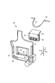
図1に示すように、画像形成装置1は、画像形成装置本体(以下、装置本体という)10を備えている。また、装置本体10は、画像読取部20と、シート給送部30と、画像形成部40と、シート搬送部50と、シート排出部60と、制御部11と、操作部12とを備えている。尚、記録材であるシートSは、トナー像が形成されるものであり、具体例として、普通紙、普通紙の代用品である樹脂製のシート、厚紙、オーバーヘッドプロジェクタ用シート等がある。
As shown in FIG. 1, the image forming apparatus 1 includes an image forming apparatus main body (hereinafter, referred to as an apparatus main body) 10. The
画像読取部20は、装置本体10の上部に設けられている。画像読取部20は、原稿載置台としての不図示のプラテンガラスと、プラテンガラスに載置された原稿に光を照射する不図示の光源と、反射光をデジタル信号に変換する不図示のイメージセンサ等を備えている。
The
シート給送部30は、シートSを積載して収容するシートカセット31a,31bと、給送ローラ32a,32bとを備え、シートSを画像形成部40に給送する。
The
画像形成部40は、画像形成ユニット41と、トナーボトル42と、レーザスキャナ43と、中間転写ユニット44と、2次転写部45と、定着装置46とを備え、画像形成を行う。
The
画像形成ユニット41は、イエロー(y)、マゼンタ(m)、シアン(c)、ブラック(k)の4色のトナー画像を形成するための4個の画像形成ユニット41y,41m,41c,41kを備えている。これらは、それぞれプロセスカートリッジとして、装置本体10に対してユーザにより着脱可能になっている(図2参照)。例えば、画像形成ユニット41yは、トナー画像を形成する像担持体である感光ドラム47yと、不図示の帯電ローラと、現像ローラと、前露光装置71(図3参照)と、クリーニングブレード72(図3参照)と、トナー回収容器等とを備えている。画像形成ユニット41yには、トナーが充填されたトナーボトル42yからトナーが供給される。尚、他の画像形成ユニット41m,41c,41kも同様の構造であるので、詳細な説明は省略する。
The
感光ドラム47は、ドラムユニット(カートリッジ)70(図2及び図3参照)に収容されており、画像形成ユニット41に対して上下方向に着脱可能である。このドラムユニット70の構成の詳細については、後述する。帯電ローラは、感光ドラム47の表面を帯電可能である。レーザスキャナ43は、感光ドラム47y,47m,47c,47kの帯電された表面を露光して、感光ドラム47y,47m,47c,47kの表面上に静電潜像を形成する。現像ローラは、形成された静電潜像を現像して可視化する。前露光装置71(図3参照)は、1次転写後の感光ドラム47y,47m,47c,47kの表面を露光する。クリーニングブレード72(図3参照)は、前露光後の感光ドラム47y,47m,47c,47kの表面に接触して、残留トナーを清掃する。
The
中間転写ユニット44は、画像形成ユニット41y,41m,41c,41kの上方に配置されている。中間転写ユニット44は、駆動ローラ44aや1次転写ローラ44y,44m,44c,44k等の複数のローラと、これらのローラに巻き掛けられた中間転写ベルト44bとを備えている。1次転写ローラ44y,44m,44c,44kは、感光ドラム47y,47m,47c,47kにそれぞれ対向して配置され、中間転写ベルト44bに当接する。中間転写ベルト44bに1次転写ローラ44y,44m,44c,44kによって正極性の転写バイアスを印加することにより、感光ドラム47y,47m,47c,47k上のそれぞれの負極性を持つトナー像が順次中間転写ベルト44bに多重転写される。これにより、中間転写ベルト44bに、フルカラー画像が形成される。
The
2次転写部45は、2次転写内ローラ45aと、2次転写外ローラ45bとを備えている。2次転写外ローラ45bに正極性の2次転写バイアスを印加することによって、中間転写ベルト44bに形成されたフルカラー画像をシートSに転写する。尚、2次転写内ローラ45aは中間転写ベルト44bの内側で該中間転写ベルト44bを張架しており、2次転写外ローラ45bは中間転写ベルト44bを挟んで2次転写内ローラ45aと対向する位置に設けられている。
The
定着装置46は、定着ローラ46a及び加圧ローラ46bを備えている。定着ローラ46aと加圧ローラ46bとの間をシートSが挟持搬送されることにより、シートSに転写されたトナー像は加熱及び加圧されてシートSに定着される。
The fixing
シート搬送部50は、シート給送部30から給送されたシートSを画像形成部40からシート排出部60に搬送するようになっており、2次転写前搬送経路51と、定着前搬送経路52と、排出経路53と、再搬送経路54とを備えている。
The
シート排出部60は、排出経路53の下流側に配置された排出ローラ対61と、排出ローラ対61の下流側に配置された排出トレイ62とを備えている。排出ローラ対61は、排出経路53から搬送されるシートSをニップ部から給送し、装置本体10に形成された排出口10aを通して排出トレイ62に排出する。
The
このように構成された画像形成装置1では、画像形成動作が開始されると、まず感光ドラム47y,47m,47c,47kが回転して表面が帯電ローラにより帯電される。そして、レーザスキャナ43により画像情報に基づいてレーザ光が感光ドラム47y,47m,47c,47kに対して発光され、感光ドラム47y,47m,47c,47kの表面上に静電潜像が形成される。この静電潜像にトナーが付着することにより、現像されてトナー画像として可視化され、中間転写ベルト44bに転写される。
In the image forming apparatus 1 configured as described above, when the image forming operation is started, first, the
一方、このようなトナー像の形成動作に並行して給送ローラ32a,32bが回転し、シートカセット31a,31bの最上位のシートSを分離しながら給送する。そして、中間転写ベルト44bのトナー画像にタイミングを合わせて、2次転写前搬送経路51を介してシートSが2次転写部45に搬送される。更に、中間転写ベルト44bからシートSに画像が転写され、シートSは、定着装置46に搬送され、ここで未定着トナー像が加熱及び加圧されてシートSの表面に定着され、排出ローラ対61により排出口10aから排出されて排出トレイ62に積載される。
On the other hand, the
次に、ドラムユニット70及び画像形成ユニット41の着脱機構について、図2乃至図4を用いて詳細に説明する。まず、図2に示すように、装置本体10の前部には、開閉可能な前カバー10bが設けられている。前カバー10bを開放することにより、画像形成ユニット41は装置本体10に対し、ガイドレール10cに案内されて前方向Fに移動可能になる。画像形成ユニット41の前方向Fの端部側には、ドラムユニット70の画像形成ユニット41に対する位置を規制する規制部材80が設けられている。
Next, the attachment / detachment mechanism of the
図3に示すように、ドラムユニット70は、感光ドラム47と、前露光装置71と、クリーニングブレード72と、これらを収容する筐体73とを有して、画像形成ユニット41に対して着脱可能に設けられている。感光ドラム47は、筐体73に対して回転可能に支持されている。
As shown in FIG. 3, the
ドラムユニット70の前方向Fの端部には、メモリ基板(記憶手段)74が設けられている。メモリ基板74は、不図示の記憶素子と、該記憶素子と電気的に接続する第1の接点(第1の電極端子)75とを有し、感光ドラム47に関する情報を記憶可能である。即ち、メモリ基板74は、ドラムユニット70の安定した作像動作に利用可能な情報を記憶する。第1の接点75は、感光ドラム47の回転中心の軸方向に関して、筐体73の端面に露出して設けられている。即ち、ドラムユニット70は、筐体73と、感光ドラム47と、装置本体10に対して電気的に接続可能な第1の接点75と、を有し、装置本体10に着脱可能に設けられている。また、第1の接点75は、メモリ基板74に設けられると共に、後述する第2の接点(第2の電極端子)81に対して接触することによりメモリ基板74と装置本体10とを通信可能に接続する。
A memory substrate (storage means) 74 is provided at an end of the
ドラムユニット70の前方向Fの端部には、下方向Dに突出した係合突起76と、左方向L及び右方向Rに面する一対の当接面(被規制部)77と、感光ドラム47と同軸上に配置された軸受78とが設けられている。当接面77は、筐体73の左右の側部に設けられている。軸受78としては、高い精度が求められるため、例えば玉軸受が用いられる。係合突起76は、画像形成ユニット41の規制部材80に対して、長手方向(前後方向)の位置決めを行う。各当接面77は、画像形成ユニット41の規制部材80に対して、上下左右方向の位置決め、及び軸受78を中心とする回転方向の姿勢決めを行う。
At an end of the
図4に示すように、規制部材80は、第1の接点75に接触可能な第2の接点81と、当接面77に当接可能な規制面(第2の規制部、回転方向規制部)82と、係合突起76に当接可能な係合穴(第1の規制部、軸方向規制部)83とを有し、装置本体10に支持される。
As shown in FIG. 4, the regulating
第2の接点81は、コネクタ84に設けられている。コネクタ84は嵌合部85を有すると共に、規制部材80はコネクタ保持部86を有している。嵌合部85がコネクタ保持部86に嵌合することにより、コネクタ84は規制部材80に一体的に取り付けられている。この時、コネクタ84の第2の接点81は、装着されたドラムユニット70の第1の接点75に対向する位置及び向きに配置されている。
The
第2の接点81は、接触により第1の接点75と装置本体10とを電気的に接続する。第2の接点81は、弾性変形可能な金属製の板ばねにより構成されている。このため、ドラムユニット70が画像形成ユニット41に装着された際に、第2の接点81が第1の接点75と当接しつつ所定量押し込まれることで、第2の接点81と第1の接点75の間には適切な接点圧を得られる。本実施の形態では、第1の接点75と第2の接点81との押圧方向が、略水平方向に構成されている。即ち、第1の接点75及び第2の接点81は、ドラムユニット70を規制部材80に対して着脱する着脱方向に直交する方向に互いに押圧して接触可能に設けられている。これにより、各接点75,81に異物が付着する可能性を低減している。
The
係合穴83は、筐体73の一部としての係合突起76に当接可能で、当接により筐体73が装置本体10に対して感光ドラム47の軸方向に移動することを規制する。このため、ドラムユニット70を画像形成ユニット41に装着すると、係合突起76が規制部材80の係合穴83に係合し、ドラムユニット70は画像形成ユニット41に対して長手方向の位置決めがなされる。このとき、ドラムユニット70は画像形成ユニット41に対して長手方向の位置決めがなされるので、第1の接点75と第2の接点81との押込み量が一定に維持される。このように、規制部材80は同一部品においてコネクタ84を保持すると共に、ドラムユニット70の長手方向の位置決めを行っているため、各接点75,81同士の接触圧のばらつきを最小限に抑え、電気接続部の安定化を図る。
The
規制面82は、筐体73の一部としての当接面77に当接可能で、当接により筐体73が装置本体10に対して感光ドラム47の回転方向に回転することを規制する。即ち、規制面82は、感光ドラム47の回転中心の軸方向に関して、筐体73の側部に設けられた当接面77に当接することにより、筐体73の回転を規制する。
The regulating
画像形成ユニット41には、各色のドラムユニット70のピッチを保証するドラムユニット間保証部材90が設けられている。ドラムユニット間保証部材90は板状で、各色ドラムユニット70が装着された際に、軸受78が嵌合するドラムユニット位置決め部91を有している。ドラムユニット間保証部材90における各色ドラムユニット70のピッチ間保証はプリント画像の品質にも大きく影響するので、非常に高精度が求められる。このため、ドラムユニット間保証部材90としては、金属製の板材が用いられている。ドラムユニット間保証部材90は、規制部材80を保持している。
The
次に、上述したドラムユニット70を画像形成装置1に対して着脱する際の動作について、図2乃至図6を用いて詳細に説明する。
Next, an operation of attaching and detaching the above-described
図2に示すように、ユーザ又はメンテナンス作業者がドラムユニット70の交換等のため着脱する際は、画像形成装置1の本体電源をオフにして、前カバー10bを開け、ねじ止め又はロック機構を解除して、画像形成ユニット41を前方向Fに引き出す。画像形成ユニット41は、不図示の現像ローラや、トナー回収容器や、各色のドラムユニット70等を備えている。このような定期的に交換すべきユニットを1つの画像形成ユニット41に実装し、まとめて引き出し可能な構成が用いられているので、交換の作業性及びメンテナンス性が向上される。
As shown in FIG. 2, when a user or a maintenance worker attaches or detaches the
画像形成ユニット41を前方向Fに引き出すと、ドラムユニット70にアクセスが可能となる。そして、図5に示す状態から、不図示の摘み部を持ってドラムユニット70を上方向Uに引抜くと、図6に示すようにドラムユニット70は画像形成ユニット41から分離する。
When the
ドラムユニット70を交換し、新しいドラムユニット70を装着する際は、上記の手順と逆の手順を実行する。この場合、図6に示すように、ドラムユニット70を規制部材80の上方から下方に向けて近接させる。そして、図5に示すように、ドラムユニット70の係合突起76を規制部材80の係合穴83に嵌入すると共に、ドラムユニット70の当接面77を規制部材80の規制面82に当接させて、ドラムユニット70を規制部材80に装着する。この時、ドラムユニット70の第1の接点75は、規制部材80の第2の接点81に所定の接触圧で接触する。その後、画像形成ユニット41を後方向Bに移動させて装置本体10に押し込み、前カバー10bを閉じることで、ドラムユニット70の交換作業が終了する。
When the
ドラムユニット70の装着後は、ドラムユニット70の係合突起76が規制部材80の係合穴83に嵌入しているので、ドラムユニット70は画像形成ユニット41に対して長手方向の位置決めがなされる。これにより、第1の接点75と第2の接点81との押込み量が一定に維持されるので、各接点75,81同士の接触圧のばらつきを最小限に抑え、電気接続部の安定化が図られる。
After the mounting of the
ここで、一般的にメモリ基板74へのアクセスは抵抗値の低い対象物に対して低電圧で行うため、アクセス状態が当接点における当接状態の影響を非常に受けやすい。また、通信中に電気的な接続状態が不安定なるとメモリ基板74に記憶されていたデータが損傷を受ける虞もあることから、各接点75,81は画像形成装置1の電気接続部の中でも特に安定性が要求される。
Here, since the access to the
一方で、電気接続安定性の要件として、各接点75,81の接触圧の他に、互いの位置ずれがある。仮に、第2の接点81が第1の接点75に対して接触していても、装置本体10の動作に伴い、ドラムユニット70と装置本体10との微小な相対位置ずれが繰り返される可能性がある。この場合、第1の接点75又は第2の接点81の酸化防止の表層メッキ(一般には金メッキ)が削れてしまい、銅箔部が露出する虞がある。銅は酸化しやすい材質であるので、第1の接点75又は第2の接点81の露出した銅箔部は酸化が進み表面抵抗が増加する可能性がある。上述した通りアクセスする電圧は低電圧であるため、表面抵抗が増加すると、接続状態が不安定となってしまう。このため、接触圧の安定化は勿論のこと、各接点75,81の位置ずれを如何に小さくするか接続状態の安定化につながる。
On the other hand, as a requirement of the electrical connection stability, there is a mutual displacement other than the contact pressure of each of the
また、装置本体10から感光ドラム47に駆動力を受けると、ドラムユニット70には感光ドラム47回り、即ち感光ドラム47の同軸上の軸受78回りに回転モーメントが発生する。ドラムユニット70にはクリーニングブレード72や従動回転の不図示の帯電ローラが当接しているため、例えば、約2kgf・cm程度の回転モーメントが発生する。この回転モーメントが規制面82に作用するため、規制部材80はドラムユニット間保証部材90に対して微小(数十μm程度)に変形や位置が変動する。即ち、メモリ基板74を有するドラムユニット70は、ドラムユニット間保証部材90も一緒に軸受78回りに微小に回転する可能性がある。
Further, when the
それに対し、本実施の形態では、規制部材80にコネクタ84が保持されているので、コネクタ84は規制部材80と一体的に移動するため、ドラムユニット70との相対位置関係は維持される。よって、第1の接点75と第2の接点81との摺擦も最小限に抑えられ、表層メッキの削れを抑制することができる。また、ドラムユニット間保証部材90に対しての位置ずれの吸収は、コネクタ84から出ている不図示の束線の余長等で行うことができる。このため、これらの構成を採用することで、電気接続部の安定的な接続が得られる。
On the other hand, in the present embodiment, since the
上述したように本実施の形態の画像形成装置1によれば、ドラムユニット70の位置を規制する規制部材80が、ドラムユニット70の第1の接点75に接続可能な第2の接点81を有している。このため、ドラムユニット70の装着後に、感光ドラム47の回転によってドラムユニット70及び規制部材80が装置本体10に対してガタを生じても、第2の接点81が規制部材80と共に移動する。これにより、ドラムユニット70と第2の接点81との相対位置は維持されるので、装置本体10に対して着脱可能なドラムユニット70と装置本体10との間で、電気的な接点同士の接続安定性を向上することができる。
As described above, according to the image forming apparatus 1 of the present embodiment, the regulating
また、本実施の形態の画像形成装置1によれば、規制面82は、感光ドラム47の回転中心の軸方向に関して、筐体73の側部に設けられた当接面77に当接することにより、筐体73の回転を規制する。このため、簡易な構成で確実に筐体73の回転を規制することができる。
According to the image forming apparatus 1 of the present embodiment, the regulating
また、本実施の形態の画像形成装置1によれば、第1の接点75及び第2の接点81は、ドラムユニット70を規制部材80に対して着脱する着脱方向に直交する方向に互いに押圧して接触可能に設けられる。このため、ドラムユニット70を規制部材80に対して着脱する際に、第1の接点75及び第2の接点81の間に無理な外力が作用することなく、着脱作業の円滑化を図り、かつ各接点75,81の損傷を防止することができる。
Further, according to the image forming apparatus 1 of the present embodiment, the
また、本実施の形態の画像形成装置1によれば、着脱方向は上下方向であるので、各接点75,81に異物が付着する可能性を低減することができる。
Further, according to the image forming apparatus 1 of the present embodiment, since the attaching / detaching direction is the vertical direction, it is possible to reduce the possibility that foreign matter adheres to each of the
また、本実施の形態の画像形成装置1によれば、第1の接点75は、感光ドラム47の回転中心の軸方向に関して、筐体73の端面に露出して設けられる。このため、規制部材80を筐体73の端部に配置することができるので、ドラムユニット70を規制部材80に対して着脱する際の作業性を向上することができる。
According to the image forming apparatus 1 of the present embodiment, the
上述した本実施の形態の画像形成装置1では、第1の接点75はドラムユニット70が有するメモリ基板74の接点とした場合について説明したが、これには限られない。例えば、前露光装置71や他のセンサ等に使用するための接点としてもよい。
In the above-described image forming apparatus 1 of the present embodiment, the case where
また、本実施の形態の画像形成装置1では、第1の接点75は筐体73の端面に露出して設けられる場合について説明したが、これには限られず、他の部位に設けられるようにしてもよい。
Further, in the image forming apparatus 1 of the present embodiment, the case where the
また、本実施の形態の画像形成装置1では、ドラムユニット70の画像形成ユニット41に対する着脱方向は上下方向である場合について説明したが、これには限られず、他の方向であってもよい。
Further, in the image forming apparatus 1 according to the present embodiment, the case where the mounting / detaching direction of the
また、本実施の形態の画像形成装置1では、当接面77が筐体73の左右の側部に設けられる場合について説明したが、これには限られず、他の部位に設けられていてもよい。同様に、本実施の形態の画像形成装置1では、係合突起76が下方向Dに突出して設けられる場合について説明したが、これには限られず、他の部位に設けられていてもよい。
Further, in the image forming apparatus 1 of the present embodiment, the case where the contact surfaces 77 are provided on the left and right sides of the
1…画像形成装置、10…装置本体、47…感光ドラム(像担持体)、70…ドラムユニット(カートリッジ)、73…筐体、74…メモリ基板(記憶手段)、75…第1の接点、76…係合突起(筐体の一部)、77…当接面(筐体の一部、被規制部)、80…規制部材、81…第2の接点、82…規制面(回転方向規制部)、83…係合穴(軸方向規制部)。 DESCRIPTION OF SYMBOLS 1 ... Image forming apparatus, 10 ... Device main body, 47 ... Photosensitive drum (image carrier), 70 ... Drum unit (cartridge), 73 ... Housing, 74 ... Memory board (storage means), 75 ... 1st contact, 76 ... Engagement projection (part of housing), 77 abutment surface (part of housing, regulated part), 80 ... regulating member, 81 ... second contact, 82 ... regulating surface (rotation direction regulating part) ), 83 ... engagement hole (axial direction regulating portion).
Claims (5)
感光ドラムと、前記感光ドラムを回転可能に支持する筐体と、データが記憶された記憶部と、前記感光ドラムの回転軸線方向における前記筐体の一端側から前記回転軸線方向に露出した第1の電極端子と、を有し、前記回転軸線方向に垂直な方向において前記画像形成装置に着脱されるドラムユニットと、
前記ドラムユニットが前記画像形成装置に装着された状態において、前記回転軸線方向において前記第1の電極端子と接触し前記記憶部に記憶されたデータを通信可能な第2の電極端子と、
前記第1の電極端子と前記第2の電極端子とが接触した状態で前記回転軸線方向における前記第1の電極端子と前記第2の電極端子との接触の圧力が変動することを抑制するために前記回転軸線方向において前記筐体に当接し前記第1の電極端子が前記回転軸線方向において前記第2の電極端子へと近付く方向と前記第2の電極端子から遠ざかる方向への移動を規制する第1の規制部と、前記第1の電極端子と前記第2の電極端子とが接触した状態で前記回転軸線方向と前記着脱される方向との双方に垂直な垂直方向における前記筐体の一方側と前記垂直方向における前記筐体の他方側とに当接し前記筐体の前記垂直方向への移動を規制する第2の規制部と、が一体成形された規制部材であって、前記第2の電極端子が一体的に設けられた規制部材と、を備える、
ことを特徴とする画像形成装置。 An image forming apparatus,
A sensitive light drum, a housing for rotatably supporting said photosensitive drum, the exposed a storage unit in which data is stored, from one end of the housing in the rotation axis direction of the photosensitive drum in the rotational axis direction a first electrode terminal, and a drum unit that is removably prior to the image forming apparatus in a direction perpendicular to Machinery guinea line direction,
A second electrode terminal capable of communicating with data stored in the storage unit by contacting the first electrode terminal in the rotation axis direction while the drum unit is mounted on the image forming apparatus;
In order to suppress a change in the pressure of contact between the first electrode terminal and the second electrode terminal in the rotation axis direction in a state where the first electrode terminal and the second electrode terminal are in contact with each other. The first electrode terminal abuts on the housing in the rotation axis direction, and regulates the movement of the first electrode terminal in the rotation axis direction toward the second electrode terminal and in the direction away from the second electrode terminal. A first regulating portion, and one of the housings in a vertical direction perpendicular to both the rotation axis direction and the detachment direction in a state where the first electrode terminal and the second electrode terminal are in contact with each other. And a second restricting portion that abuts against the other side of the casing in the vertical direction and regulates movement of the casing in the vertical direction. With integrated electrode terminals Comprising a member,
An image forming apparatus comprising:
前記規制部材は前記引き出しユニットに設けられており、前記ドラムユニットが前記引き出しユニットに装着されることに伴い前記第1の電極端子と前記第2の電極端子とが当接する、
ことを特徴とする請求項1に記載の画像形成装置。 A drawer unit configured to be able to be pulled out from the image forming apparatus and to which the drum unit is attached,
The regulating member is provided on the drawer unit, and the first electrode terminal and the second electrode terminal come into contact with the drum unit being mounted on the drawer unit,
The image forming apparatus according to claim 1, wherein:
ことを特徴とする請求項1又は2に記載の画像形成装置。 Wherein the housing is formed projection which projects in a direction in which the drum unit is mounted to the image forming apparatus, said projection and said first restricting portion in a state in which the drum unit is mounted to the image forming apparatus Abuts , and the movement of the drum unit in the rotation axis direction is regulated.
The image forming apparatus according to claim 1, wherein:
ことを特徴とする請求項3に記載の画像形成装置。 The first restricting portion is a hole formed in the restricting member, in which the protrusion fits.
The image forming apparatus according to claim 3, wherein:
ことを特徴とする請求項1乃至4のいずれか1項に記載の画像形成装置。 The attaching / detaching direction is a vertical direction,
The image forming apparatus according to any one of claims 1 to 4, characterized in that.
Priority Applications (1)
| Application Number | Priority Date | Filing Date | Title |
|---|---|---|---|
| JP2015166746A JP6659103B2 (en) | 2015-08-26 | 2015-08-26 | Image forming device |
Applications Claiming Priority (1)
| Application Number | Priority Date | Filing Date | Title |
|---|---|---|---|
| JP2015166746A JP6659103B2 (en) | 2015-08-26 | 2015-08-26 | Image forming device |
Publications (2)
| Publication Number | Publication Date |
|---|---|
| JP2017044845A JP2017044845A (en) | 2017-03-02 |
| JP6659103B2 true JP6659103B2 (en) | 2020-03-04 |
Family
ID=58211167
Family Applications (1)
| Application Number | Title | Priority Date | Filing Date |
|---|---|---|---|
| JP2015166746A Expired - Fee Related JP6659103B2 (en) | 2015-08-26 | 2015-08-26 | Image forming device |
Country Status (1)
| Country | Link |
|---|---|
| JP (1) | JP6659103B2 (en) |
Families Citing this family (1)
| Publication number | Priority date | Publication date | Assignee | Title |
|---|---|---|---|---|
| JP7367317B2 (en) | 2019-03-27 | 2023-10-24 | ブラザー工業株式会社 | Image forming device |
Family Cites Families (12)
| Publication number | Priority date | Publication date | Assignee | Title |
|---|---|---|---|---|
| JP2005070186A (en) * | 2003-08-20 | 2005-03-17 | Canon Inc | Process cartridge and electrophotographic image forming apparatus |
| US20060285132A1 (en) * | 2005-06-21 | 2006-12-21 | Samsung Electronics Co., Ltd. | Electrophotographic image forming apparatus |
| JP4095649B1 (en) * | 2006-12-28 | 2008-06-04 | キヤノン株式会社 | Electrophotographic image forming apparatus, process cartridge, and moving member |
| JP2008185971A (en) * | 2007-01-31 | 2008-08-14 | Ricoh Co Ltd | Image forming apparatus |
| JP4689750B2 (en) * | 2008-09-29 | 2011-05-25 | キヤノン株式会社 | Electrophotographic image forming apparatus |
| JP5447938B2 (en) * | 2009-09-01 | 2014-03-19 | 株式会社リコー | Image forming apparatus |
| JP5499768B2 (en) * | 2010-02-25 | 2014-05-21 | 富士ゼロックス株式会社 | Image forming apparatus |
| JP5761948B2 (en) * | 2010-09-14 | 2015-08-12 | キヤノン株式会社 | Electrophotographic image forming apparatus |
| JP5518146B2 (en) * | 2012-08-10 | 2014-06-11 | キヤノン株式会社 | Process cartridge and image forming apparatus using the same |
| JP6095349B2 (en) * | 2012-12-10 | 2017-03-15 | キヤノン株式会社 | Image forming apparatus and support member |
| JP6175862B2 (en) * | 2013-03-29 | 2017-08-09 | ブラザー工業株式会社 | Image forming apparatus |
| JP2014228609A (en) * | 2013-05-21 | 2014-12-08 | 京セラドキュメントソリューションズ株式会社 | Image forming apparatus |
-
2015
- 2015-08-26 JP JP2015166746A patent/JP6659103B2/en not_active Expired - Fee Related
Also Published As
| Publication number | Publication date |
|---|---|
| JP2017044845A (en) | 2017-03-02 |
Similar Documents
| Publication | Publication Date | Title |
|---|---|---|
| JP5000380B2 (en) | Image forming apparatus and process unit | |
| US9310762B2 (en) | Process cartridge and electrophotographic image forming apparatus | |
| US7248810B2 (en) | Cartridge, process cartridge, and electrophotographic image forming apparatus | |
| US9304483B2 (en) | Cartridge, image forming apparatus and main assembly of image forming apparatus | |
| US8401418B2 (en) | Image forming apparatus | |
| JP5043493B2 (en) | Image forming apparatus | |
| US10935928B2 (en) | Cartridge | |
| JP2010164993A (en) | Image forming apparatus | |
| US10261463B2 (en) | Image forming apparatus | |
| US11567447B2 (en) | Process cartridge and image forming apparatus | |
| US10073408B2 (en) | Image forming apparatus including a pressing member configured to press a development unit | |
| US9052686B2 (en) | Process cartridge | |
| JP2012073491A (en) | Image formation device | |
| US8918014B2 (en) | Electrophotographic image forming apparatus | |
| US20130209138A1 (en) | Electrophotographic image forming apparatus | |
| US8401429B2 (en) | Image forming apparatus | |
| JP6659103B2 (en) | Image forming device | |
| US10459401B2 (en) | Image forming apparatus | |
| JP2014056012A (en) | Process cartridge | |
| CN110967954B (en) | Transfer belt unit and image forming apparatus | |
| US9122235B2 (en) | Process cartridge and image forming apparatus with means to regulate movement of developing unit with respect to drum unit in axial direction of developing roller | |
| CN112051718B (en) | Transfer belt unit and image forming apparatus including the same | |
| JP2021134005A (en) | Media transfer device and image formation apparatus | |
| JP2020071366A (en) | Developing device and image forming apparatus | |
| JP2020046685A (en) | Image forming apparatus |
Legal Events
| Date | Code | Title | Description |
|---|---|---|---|
| A621 | Written request for application examination |
Free format text: JAPANESE INTERMEDIATE CODE: A621 Effective date: 20180814 |
|
| A131 | Notification of reasons for refusal |
Free format text: JAPANESE INTERMEDIATE CODE: A131 Effective date: 20190521 |
|
| A977 | Report on retrieval |
Free format text: JAPANESE INTERMEDIATE CODE: A971007 Effective date: 20190522 |
|
| A521 | Request for written amendment filed |
Free format text: JAPANESE INTERMEDIATE CODE: A523 Effective date: 20190722 |
|
| A131 | Notification of reasons for refusal |
Free format text: JAPANESE INTERMEDIATE CODE: A131 Effective date: 20191001 |
|
| A521 | Request for written amendment filed |
Free format text: JAPANESE INTERMEDIATE CODE: A523 Effective date: 20191128 |
|
| TRDD | Decision of grant or rejection written | ||
| A01 | Written decision to grant a patent or to grant a registration (utility model) |
Free format text: JAPANESE INTERMEDIATE CODE: A01 Effective date: 20200107 |
|
| A61 | First payment of annual fees (during grant procedure) |
Free format text: JAPANESE INTERMEDIATE CODE: A61 Effective date: 20200204 |
|
| R151 | Written notification of patent or utility model registration |
Ref document number: 6659103 Country of ref document: JP Free format text: JAPANESE INTERMEDIATE CODE: R151 |
|
| LAPS | Cancellation because of no payment of annual fees |