JP6658361B2 - Water coagulator, fuel filter device, and method of manufacturing water coagulator - Google Patents
Water coagulator, fuel filter device, and method of manufacturing water coagulator Download PDFInfo
- Publication number
- JP6658361B2 JP6658361B2 JP2016133710A JP2016133710A JP6658361B2 JP 6658361 B2 JP6658361 B2 JP 6658361B2 JP 2016133710 A JP2016133710 A JP 2016133710A JP 2016133710 A JP2016133710 A JP 2016133710A JP 6658361 B2 JP6658361 B2 JP 6658361B2
- Authority
- JP
- Japan
- Prior art keywords
- water
- frame
- fiber layer
- layer
- fuel
- Prior art date
- Legal status (The legal status is an assumption and is not a legal conclusion. Google has not performed a legal analysis and makes no representation as to the accuracy of the status listed.)
- Active
Links
- XLYOFNOQVPJJNP-UHFFFAOYSA-N water Substances O XLYOFNOQVPJJNP-UHFFFAOYSA-N 0.000 title claims description 193
- 239000000446 fuel Substances 0.000 title claims description 143
- 238000004519 manufacturing process Methods 0.000 title claims description 25
- 239000000835 fiber Substances 0.000 claims description 187
- 239000000463 material Substances 0.000 claims description 134
- 238000004804 winding Methods 0.000 claims description 47
- 238000005304 joining Methods 0.000 claims description 39
- 238000000926 separation method Methods 0.000 claims description 33
- 230000002093 peripheral effect Effects 0.000 claims description 25
- 238000000034 method Methods 0.000 claims description 24
- 239000007787 solid Substances 0.000 claims description 8
- 230000001112 coagulating effect Effects 0.000 claims description 5
- 230000004931 aggregating effect Effects 0.000 claims description 4
- 238000010168 coupling process Methods 0.000 claims description 4
- 238000005859 coupling reaction Methods 0.000 claims description 4
- 239000010410 layer Substances 0.000 description 303
- 230000007246 mechanism Effects 0.000 description 23
- 239000011347 resin Substances 0.000 description 17
- 229920005989 resin Polymers 0.000 description 17
- 239000008186 active pharmaceutical agent Substances 0.000 description 14
- 230000008569 process Effects 0.000 description 14
- 239000002994 raw material Substances 0.000 description 11
- 238000002485 combustion reaction Methods 0.000 description 10
- 239000000853 adhesive Substances 0.000 description 8
- 230000001070 adhesive effect Effects 0.000 description 8
- 239000012530 fluid Substances 0.000 description 7
- 238000002844 melting Methods 0.000 description 7
- 230000008018 melting Effects 0.000 description 7
- 238000003825 pressing Methods 0.000 description 7
- 238000011144 upstream manufacturing Methods 0.000 description 7
- 238000001914 filtration Methods 0.000 description 5
- 239000002828 fuel tank Substances 0.000 description 5
- 238000007789 sealing Methods 0.000 description 5
- 230000008901 benefit Effects 0.000 description 4
- 238000005345 coagulation Methods 0.000 description 4
- 230000015271 coagulation Effects 0.000 description 4
- 238000001514 detection method Methods 0.000 description 4
- 230000002776 aggregation Effects 0.000 description 3
- 238000004220 aggregation Methods 0.000 description 3
- 230000001427 coherent effect Effects 0.000 description 3
- 230000008878 coupling Effects 0.000 description 3
- 238000000354 decomposition reaction Methods 0.000 description 3
- 238000005189 flocculation Methods 0.000 description 3
- 230000016615 flocculation Effects 0.000 description 3
- 230000004048 modification Effects 0.000 description 3
- 238000012986 modification Methods 0.000 description 3
- 230000000149 penetrating effect Effects 0.000 description 3
- 238000004062 sedimentation Methods 0.000 description 3
- 238000005520 cutting process Methods 0.000 description 2
- 238000002347 injection Methods 0.000 description 2
- 239000007924 injection Substances 0.000 description 2
- 230000001788 irregular Effects 0.000 description 2
- 229910052751 metal Inorganic materials 0.000 description 2
- 239000002184 metal Substances 0.000 description 2
- 239000005871 repellent Substances 0.000 description 2
- 239000002699 waste material Substances 0.000 description 2
- 229910000838 Al alloy Inorganic materials 0.000 description 1
- 239000004215 Carbon black (E152) Substances 0.000 description 1
- 235000007516 Chrysanthemum Nutrition 0.000 description 1
- 244000189548 Chrysanthemum x morifolium Species 0.000 description 1
- 241000280258 Dyschoriste linearis Species 0.000 description 1
- 229920000297 Rayon Polymers 0.000 description 1
- 239000003225 biodiesel Substances 0.000 description 1
- 238000004891 communication Methods 0.000 description 1
- 238000010586 diagram Methods 0.000 description 1
- 238000007599 discharging Methods 0.000 description 1
- 230000000694 effects Effects 0.000 description 1
- 230000005489 elastic deformation Effects 0.000 description 1
- 230000003311 flocculating effect Effects 0.000 description 1
- 230000009969 flowable effect Effects 0.000 description 1
- -1 for example Substances 0.000 description 1
- 239000003502 gasoline Substances 0.000 description 1
- 230000005484 gravity Effects 0.000 description 1
- 229930195733 hydrocarbon Natural products 0.000 description 1
- 150000002430 hydrocarbons Chemical class 0.000 description 1
- 230000002209 hydrophobic effect Effects 0.000 description 1
- 238000003780 insertion Methods 0.000 description 1
- 230000037431 insertion Effects 0.000 description 1
- 239000004745 nonwoven fabric Substances 0.000 description 1
- 238000005192 partition Methods 0.000 description 1
- 230000035515 penetration Effects 0.000 description 1
- 230000000704 physical effect Effects 0.000 description 1
- 239000002964 rayon Substances 0.000 description 1
- 230000009467 reduction Effects 0.000 description 1
- 230000002940 repellent Effects 0.000 description 1
- 239000002356 single layer Substances 0.000 description 1
- 239000000126 substance Substances 0.000 description 1
- 229920001169 thermoplastic Polymers 0.000 description 1
- 239000004416 thermosoftening plastic Substances 0.000 description 1
- 238000003466 welding Methods 0.000 description 1
Images


Description
この明細書における開示は、燃料中に含まれる水を凝集させる水凝集器に関する。開示は、燃料フィルタ装置、および水凝集器の製造方法にわたる。 The disclosure in this specification relates to a water flocculator for flocculating water contained in fuel. The disclosure extends to a method of manufacturing a fuel filter device and a water aggregator.
特許文献1−5は、燃料フィルタ装置を開示する。これら燃料フィルタ装置は、燃料を濾過することによって固形の異物を除去するためのフィルタと、燃料に含まれる水を凝集させ、分離するための水分離器とを備える。水を燃料から分離させる性能の少なくとも一部は、水を凝集させて大きい水滴に成長させる性能、すなわち水を凝集させる性能によって評価することができる。大きい水滴は、重力分離、衝突分離、撥水層による分離など、既知の分離技術によって分離されやすい利点をもつ。特許文献1−5では、水凝集層によって水を凝集させる水凝集器の利用が試みられている。従来技術として列挙された先行技術文献の記載内容は、この明細書における技術的要素の説明として、参照により援用される。 Patent documents 1-5 disclose a fuel filter device. These fuel filter devices include a filter for removing solid foreign matter by filtering fuel, and a water separator for coagulating and separating water contained in the fuel. At least a part of the performance of separating water from the fuel can be evaluated by the performance of coagulating water to grow into large water droplets, that is, the performance of coagulating water. Large water droplets have the advantage of being easily separated by known separation techniques, such as gravity separation, collision separation, separation by a water-repellent layer. In Patent Literatures 1 to 5, an attempt is made to use a water aggregator in which water is aggregated by a water aggregation layer. Descriptions of the prior art documents listed as prior art are incorporated by reference as descriptions of technical elements in this specification.
高い水凝集性能を発揮するため、厚い凝集層が求められる場合がある。しかし、厚い凝集層は、いくつかの異なる課題を有している。 In order to exhibit high water coagulation performance, a thick coagulation layer may be required. However, thick cohesive layers have several different challenges.
ひとつの観点において、厚い凝集層は、確実な固定が困難である。燃料の流れの中において、厚い凝集層の圧潰、分解を抑制しながら、その厚さと、広い表面積とを維持する必要がある。 In one aspect, thick cohesive layers are difficult to secure securely. In the flow of fuel, it is necessary to maintain the thickness and the large surface area while suppressing the collapse and decomposition of the thick agglomerated layer.
他のひとつの観点において、厚い単一の凝集層は、製造が困難である。厚い単一の凝集層は、製造工程における加工および製造工程における取り扱いが困難である。このため、厚い単一の凝集層は、製造工程において特別の配慮を必要とする。 In another aspect, a single thick coherent layer is difficult to manufacture. A single thick coherent layer is difficult to process and handle in the manufacturing process. For this reason, a single thick coherent layer requires special consideration in the manufacturing process.
上述の観点において、または言及されていない他の観点において、水凝集器、および燃料フィルタ装置にはさらなる改良が求められている。 In view of the above, or other aspects not mentioned, there is a need for further improvements in water aggregators and fuel filter devices.
開示されるひとつの目的は、厚い凝集層を有する水凝集器、燃料フィルタ装置、および水凝集器の製造方法を提供することである。 One object disclosed is to provide a water flocculator, a fuel filter device, and a method of manufacturing a water flocculator having a thick flocculation layer.
開示される他のひとつの目的は、製造が容易な厚い凝集層を有する水凝集器、燃料フィルタ装置、および水凝集器の製造方法を提供することである。 Another object disclosed is to provide a water aggregator, a fuel filter device, and a method for manufacturing a water aggregator having a thick agglomerated layer that is easy to manufacture.
開示されるさらに他のひとつの目的は、少ない部品点数で厚い凝集層を固定できる水凝集器、燃料フィルタ装置、および水凝集器の製造方法を提供することである。 Still another object disclosed is to provide a water flocculator, a fuel filter device, and a method of manufacturing a water flocculator capable of fixing a thick flocculated layer with a small number of parts.
ここに開示された水凝集器は、径方向への燃料の流れを許容するフレーム(51)、フレームに装着され、燃料の中の水を凝集させる筒状の繊維層であって、径方向に関して2層以上に重なるように2周以上に配置された帯状の素材(62)のロール体を含む繊維層(61)、および繊維層をフレームに固定する複数の接合部(71)を備え、複数の接合部は、繊維層の筒状の周面において分散して配置されている。開示される水凝集器は、帯状の素材のロール体によって繊維層が提供される。素材は、径方向に関して2層以上に重なるように2周以上に配置されている。帯状の素材を用いて、厚い繊維層が得られる。また、帯状の素材を用いるから、取り扱いの容易さ、無駄の少なさといった観点から、製造上の利点が得られる。 The water aggregator disclosed herein is a frame (51) that allows a flow of fuel in a radial direction, a tubular fiber layer mounted on the frame, and aggregating water in the fuel. A fiber layer (61) including a roll of a band-shaped material (62) arranged at least two times so as to overlap two or more layers, and a plurality of joints (71) for fixing the fiber layer to a frame ; junction is that are dispersedly arranged in the cylindrical circumferential surface of the fiber layer. In the disclosed water flocculator, the fiber layer is provided by a roll of a band-shaped material. The materials are arranged in two or more turns so as to overlap two or more layers in the radial direction. A thick fiber layer can be obtained using a band-shaped material. In addition, since a band-shaped material is used, an advantage in manufacturing is obtained from the viewpoint of easy handling and low waste.
ここに開示された水凝集器は、径方向への燃料の流れを許容するフレーム(51)、フレームに装着され、燃料の中の水を凝集させる筒状の繊維層であって、径方向に関して少なくとも部分的に2層以上に重なるように配置された帯状の素材(62)のロール体を含む繊維層(61)、および繊維層をフレームに固定する複数の接合部(71)を備え、複数の接合部は、フレームから少なくともひとつの介在層を隔てて配置された最後の層をなす素材を、介在層を通してフレームに接合する貫通接合部(71b)を有する。開示される水凝集器は、筒状の繊維層を備える。繊維層は、複数の接合部によってフレームに固定されている。複数の接合部は、確実な固定を提供する。また、複数の接合部は、貫通接合部を有する。貫通接合部は、フレームから少なくともひとつの介在層を隔てて配置された最後の層をなす素材を、介在層を通してフレームに接合する。貫通接合部は、厚い繊維層を維持しながら、最後の層をフレームに固定する。よって、燃料の流れに起因する繊維層の破損が抑制される。 The water aggregator disclosed herein is a frame (51) that allows a flow of fuel in a radial direction, a tubular fiber layer mounted on the frame, and aggregating water in the fuel. A fiber layer (61) including a roll of a band-shaped material (62) arranged so as to at least partially overlap two or more layers, and a plurality of joints (71) for fixing the fiber layer to a frame; Has a penetrating joint (71b) that joins the material constituting the last layer disposed at least one intervening layer away from the frame to the frame through the intervening layer. The disclosed water aggregator comprises a tubular fiber layer. The fiber layer is fixed to the frame by a plurality of joints. Multiple joints provide secure fixation. In addition, the plurality of joints have penetrating joints. The through joint joins the last layer of material, which is disposed with at least one intervening layer separated from the frame, to the frame through the intervening layer. The through joint secures the last layer to the frame while maintaining a thick fiber layer. Therefore, breakage of the fiber layer due to the fuel flow is suppressed.
ここに開示された燃料フィルタ装置は、上記水凝集器(32、232、532)と、燃料から固形の異物を除去するフィルタ(31、231)と、燃料の通路を区画形成するとともに、水凝集器とフィルタとを収容するケース(6)とを備える。 The fuel filter device disclosed herein includes a water aggregator (32, 232, 532), a filter (31, 231) for removing solid foreign matter from the fuel, a fuel passage, and a water aggregator. A case (6) for accommodating the container and the filter.
ここに開示された水凝集器の製造方法は、径方向への燃料の流れを許容するフレーム(51)と、燃料の中の水を凝集させる筒状の繊維層とを有する水凝集器の製造方法において、フレームの内側または外側において、燃料の中の水を凝集させる帯状の素材(62)を少なくとも部分的に2層以上に重なるように巻くことにより、素材のロール体を形成する巻き工程、および繊維層をフレームに接合する接合工程を備え、巻き工程は、フレームから少なくともひとつの介在層を隔てて最後の層を配置する工程を有し、接合工程は、最後の層をなす素材を、介在層を通してフレームに接合する工程を有する。開示される水凝集器の製造方法では、帯状の素材が少なくとも部分的に2層以上に重なるように巻かれる。この結果、最後の層は、フレームから少なくともひとつの介在層を隔てて配置される。接合工程では、最後の層をなす素材が、介在層を通してフレームに接合される。この方法によると、繊維層を巻き工程によって製造することができる。しかも、接合工程により、繊維層が確実にフレームに固定される。 The method of manufacturing a water aggregator disclosed herein is directed to manufacturing a water aggregator having a frame (51) that allows fuel flow in a radial direction and a tubular fiber layer that aggregates water in the fuel. Winding a band-shaped material (62) for aggregating water in the fuel at least partially in two or more layers inside or outside the frame, thereby forming a roll of the material. And a joining step of joining the fiber layer to the frame, the winding step includes a step of arranging the last layer with at least one intervening layer separated from the frame, and the joining step includes: forming a material forming the last layer; And bonding the frame to the frame through the intervening layer. In the disclosed method for manufacturing a water flocculator, the strip-shaped material is wound so as to at least partially overlap two or more layers. As a result, the last layer is located at least one intervening layer away from the frame. In the joining step, the material forming the last layer is joined to the frame through the intervening layer. According to this method, the fiber layer can be manufactured by the winding step. In addition, the fiber layer is securely fixed to the frame by the joining step.
この明細書における開示された複数の態様は、それぞれの目的を達成するために、互いに異なる技術的手段を採用する。請求の範囲およびこの項に記載した括弧内の符号は、後述する実施形態の部分との対応関係を例示的に示すものであって、技術的範囲を限定することを意図するものではない。この明細書に開示される目的、特徴、および効果は、後続の詳細な説明、および添付の図面を参照することによってより明確になる。 The embodiments disclosed in this specification employ different technical means to achieve their respective objects. The reference numerals in parentheses described in the claims and this section exemplarily show the correspondence with the parts of the embodiment described later, and are not intended to limit the technical scope. The objects, features, and advantages disclosed in this specification will become more apparent with reference to the following detailed description and the accompanying drawings.
図面を参照しながら、複数の実施形態を説明する。複数の実施形態において、機能的におよび/または構造的に対応する部分および/または関連付けられる部分には同一の参照符号、または百以上の位が異なる参照符号が付される場合がある。対応する部分および/または関連付けられる部分については、他の実施形態の説明を参照することができる。 A plurality of embodiments will be described with reference to the drawings. In embodiments, functionally and / or structurally corresponding parts and / or associated parts may be provided with the same reference signs or reference signs that differ by more than a hundred places. For corresponding parts and / or associated parts, the description of the other embodiments can be referred to.
第1実施形態
<燃料供給装置>
図1には、車両に搭載された燃料供給装置1における燃料フィルタ装置2の断面が図示されている。図中には、燃料の流れ方向が太線矢印によって示されている。燃料供給装置1は、燃料タンク(TNK)3から燃料消費装置としての内燃機関(ENG)4へ燃料を供給する。内燃機関4の一例は、軽油を燃料とするディーゼルエンジンである。内燃機関4の種類は限定されない。例えば、ガソリン、バイオディーゼル、など多様な炭化水素燃料を利用する内燃機関を適用対象とすることができる。内燃機関4は、機械の動力源として利用される。例えば、内燃機関4は、車両の走行用動力源を提供する。内燃機関4には、燃料供給装置1の一部でもある高圧ポンプと、燃料噴射弁とが設けられている。
First embodiment <Fuel supply device>
FIG. 1 shows a cross section of a
燃料供給装置1は、燃料タンク3内の燃料を汲み上げる低圧ポンプを有する。低圧ポンプは、燃料フィルタ装置2と燃料タンク3との間、または、燃料フィルタ装置2と内燃機関4との間に設けられている。図示の例では、低圧ポンプは燃料タンク3内に収容されている。低圧ポンプによって加圧された燃料は、燃料フィルタ装置2に供給される。燃料フィルタ装置2は、燃料をろ過する。燃料フィルタ装置2によって濾過された燃料は、高圧ポンプおよび燃料噴射弁を経由して内燃機関4に供給される。
The fuel supply device 1 has a low-pressure pump that pumps up the fuel in the
<燃料フィルタ装置>
燃料フィルタ装置2は、ケース6と、フィルタユニット7とを有する。ケース6は、フィルタユニット7を収容している。ケース6は、燃料の入口11と、燃料の出口12とを有する。ケース6は、キャップ21とカップ22とを有する。キャップ21は、燃料フィルタ装置2を固定するための保持ブラケットを提供する。保持ブラケットは、燃料フィルタ装置2を車両に固定するために利用される。キャップ21とカップ22とは、フィルタユニット7を交換するために分離可能である。カップ22が、キャップ21から取り外されることにより、フィルタユニット7が露出し、交換可能な状態となる。ケース6は、金属製または樹脂製である。キャップ21は、金属製、例えばアルミニウム合金製である。カップ22は、樹脂製である。
<Fuel filter device>
The
図2において、燃料フィルタ装置2の断面が図示されている。ケース6は、入口11から延びる入口通路13を有する。入口通路13は、未濾過の燃料が流れるダーティサイドDSの一部を提供する。ケース6は、出口12から延びる出口通路14を有する。出口通路14は、濾過済みの燃料が流れるクリーンサイドCSの一部を提供する。ケース6は、入口11と出口12とを連通する燃料の流路を提供する。キャップ21とカップ22とは、それらの内部に燃料の通路としての空洞を区画形成している。キャップ21とカップ22とは、ダーティサイドDSとクリーンサイドCSとを含む室を区画形成する。ダーティサイドDSには入口通路13が連通している。クリーンサイドCSには出口通路14が連通している。
FIG. 2 shows a cross section of the
ケース6は、フィルタユニット7を収容する容器を提供する部材でもある。ケース6は、フィルタユニットを取り出すために開くことができる。キャップ21とカップ22とは、着脱可能に構成されている。キャップ21は、固定的に配置された第1ケース部分を提供する。カップ22は、着脱可能な第2ケース部分を提供する。
The
キャップ21とカップ22との間には、それらを着脱可能に連結する連結機構23が設けられている。連結機構23は、キャップ21に設けられた雌ねじと、カップ22に設けられた雄ねじとを含むねじ機構によって提供されている。連結機構23は、キャップ21とカップ22との間のシールを提供するシール部材を含むことができる。
A
カップ22の底部には、ドレン穴24と、ドレンプラグ25とが設けられている。ドレン穴24と、ドレンプラグ25とは、カップ22の底部に溜まる水分および異物を排出するための排出機構を提供する。
A
カップ22の底部には、水位センサ26が設けられている。水位センサ26は、カップ22内に溜まる水の水位が所定の水準に到達すると検出信号を出力する。水位センサ26は、フロート27と、サポート柱28とを有する。サポート柱28は、カップ22の底部から上へ向けて延び出すように配置されている。フロート27は、サポート柱28に沿って浮動可能である。フロート27は、水位に対応して浮動する。例えば、サポート柱28の中には、マグネットスイッチが収容されている。フロート27には、永久磁石が収容されている。これにより、フロート27が所定の高さに到達すると、マグネットスイッチが検出信号を出力する。
A
フィルタユニット7は、ケース6に対して着脱可能に装着されている。フィルタユニット7は、交換可能である。フィルタユニット7は、カップ22の開口端に装着されている。フィルタユニット7が装着されたカップ22が、キャップ21内に挿入され、連結機構23によってキャップ21とカップ22とが連結されることにより、フィルタユニット7は正規の位置に位置付けられる。正規の位置において、フィルタユニット7は、ダーティサイドDSとクリーンサイドCSとを仕切る。
The
フィルタユニット7は、燃料フィルタ装置2の基本機能を提供する基本要素と、付加的な機能を提供する付加要素とを有する。基本要素は、燃料を濾過することにより固形の異物を除去するフィルタ31である。付加要素は、燃料の中の水分を分離する水分離器である。水分離器は、燃料の中の水分を捕捉し、水滴を形成し、水滴を大きく成長させる凝集段階と、水滴を燃料から分離させる分離段階とを含む。凝集段階は、水分を捕捉する繊維層を有する水凝集器32によって提供される。分離段階は、水滴を沈降させる沈降分離室によって提供される。沈降分離室は、ケース6内に区画形成されている。水分離器は、ダーティサイドDSの中に配置されている。
The
フィルタ31は、フレーム41を有する。フレーム41は、キャップ21とカップ22との間に配置された場合に、ダーティサイドDSとクリーンサイドCSとを仕切る部材である。さらに、フレーム41は、ダーティサイドDSからクリーンサイドCSへの燃料の流れを許容する濾過通路を区画形成する部材でもある。
The
フレーム41は、エレメント42を支持するための部材でもある。エレメント42は、燃料から異物を除去するための濾材によって形成されている。エレメント42を形成する濾材は、紙とも呼べる繊維製品である。濾材は、その厚さ方向に燃料を流すことにより異物を除去する。エレメント42は、濾過通路を横切るように配置されている。エレメント42は、濾過通路を流れる燃料を濾過する。エレメント42は、ほぼ円柱状に形成されている。エレメント42は、濾材によって形成された多数の筒を含む。多数の筒は、円柱状に束ねられている。多数の筒は、円柱の軸方向に沿って燃料を流すことにより燃料を濾過する。エレメント42は、軸方向流型のフィルタである。図示の例では、エレメント42の下端から上端へ燃料が流れる。
The
フレーム41は、カバー部分43と、接続部分44と、センタパイプ45とを有する。カバー部分43は、エレメント42の流出端を覆うようにエレメント42と連結されている。カバー部分43の径方向外側の縁は、キャップ21およびカップ22によって提供されるケースとシール状態で接触している。
The
接続部分44は、ケース6の壁面にシール状態で連結されている。接続部分44には、シール部材としてのリップシールが設けられている。接続部分44は、ケース6における入口通路13の開口端と出口通路14の開口端との間に位置づけられている。接続部分44は、ダーティサイドDSとクリーンサイドCSとを仕切る部材でもある。
The
センタパイプ45は、エレメント42の中心部を軸方向に沿って貫通するように延びる筒状部材である。センタパイプ45は、その内部に、接続部分44の径方向内側から軸方向に延びる入口通路を区画形成している。センタパイプ45は、エレメント42によって濾過される前の燃料を通すための燃料通路を形成する通路部材である。センタパイプ45は、水凝集器32と連結される連結管46を有する。連結管46は、水凝集器32に燃料を供給するように、水凝集器32に分離可能に連結される第1連結部とも呼ばれる。連結管46は、エレメント42から突出するセンタパイプ45の突出部分の外側面に設けられている。さらに、センタパイプ45は、その先端に開口47を有する。センタパイプ45は、ケース内において燃料通路としての開口47を区画する開口区画部材でもある。開口47は、キャップ21とカップ22とが区画形成するケースの中央部に開口している。
The
フィルタユニット7は、キャップ21とカップ22との間に挟まれて保持されている。カバー部分43は、接続部分44とキャップ21との間、およびカバー部分43の外縁とカップ22との間において保持されている。
The
水凝集器32は、円筒状の外観をもつ部材として形成されている。水凝集器32は、フレーム51と、繊維層61とを有する。フレーム51は、径方向への燃料の流れを許容するように径方向に複数の開口を有している。フレーム51は、繊維層61を支持している。フレーム51は、カゴ型のホルダまたはボビンとも呼ぶことができる。フレーム51は、上側の端板52と、下側の端板53とを有する。端板52、53は、スナップフィット、接着、または溶着によって連結されている。フレーム51は、樹脂製である。この樹脂は、熱可塑性である。
The
ケース6と水凝集器32とは、ケース6と水凝集器32とを連結する連結機構を有する。連結機構は、カップ22に設けられた係合部22aと、フレーム51に設けられた係合部51aとを有する。係合部22a、51aは、樹脂材料の弾性変形を利用して係合、離脱が可能なスナップフィット機構を提供している。係合機構は、フィルタユニット7がケース6から取り出される際に、カップ22内に水凝集器32が残されるように、ケース6と水凝集器32とを連結する。係合部22a、51aが提供する連結機構による連結強度は、連結管46が提供する連結強度より強い。
The
カップ22内から、フィルタ31が上方向へ引き抜かれる場合、係合部22a、51aはカップ22と水凝集器32との連結状態を維持するが、連結管46はフィルタ31と水凝集器32とを分離させる。この構成は、水凝集器32の再利用を促し、フィルタ31だけの交換を促す。水凝集器32は、フィルタ31より目詰りしにくい。水凝集器32は、フィルタ31より長期間の使用に耐える。この構成は、交換により生じるコストの抑制を可能とする。
When the
繊維層は、筒状である。繊維層61は、フレーム51の上に保持されている。繊維層61は、フレーム51に装着されている。繊維層61は、凝集層とも呼ばれる。繊維層61は、燃料の中の水分を凝集させる水凝集部材を提供する。繊維層61は、燃料の中に分散する微小な水滴を捕捉し、凝集させる。繊維層61は、水分を捕捉し、水滴の大きさを成長させる。繊維層61は、凝集して大きく成長した水滴を再び燃料の中に放ち、カップ22内において沈降させる。繊維層61は、水滴を捕捉するために適した物理的特性と、化学的特性とを有する繊維によって形成されている。
The fiber layer is cylindrical. The
繊維層61は、フィルタ31の濾材よりも大きい空隙を提供する。フィルタ31は、求められる最小異物を除去するために、比較的小さい孔を有する。一方、繊維層61は、求められる最小異物を除去することができない。繊維層61は、比較的大きい孔を有する。また、繊維層61は、フィルタ31の濾材の流れ方向の厚さよりも遥かに厚い厚さを有している。また、繊維層61は、その比較的高い空隙率と、厚さとに起因して、フィルタ31の濾材よりも柔らかい。
The
繊維層61については特許文献1−特許文献5を参照することができる。特許文献1−特許文献5の記載内容は参照によって、この明細書に導入される。例えば、繊維層61は、親水性の繊維、例えばレーヨンである。
Patent Documents 1 to 5 can be referred to for the
<水凝集器>
図3および図4は、水凝集器32を示す断面図である。図3は、図4のIII−III線における断面を示す。図4は、図3のIV−IV線における断面を示す。フレーム51は、長尺物を巻き取るためのボビンに似た形状を有する。フレーム51は、両方の端板52、53を有する。端板52、53は、互いに対向するように配置されている。フレーム51は、端板52、53の間に配置されたコア54を有する。コア54は、繊維層61のための巻き芯でもある。コア54は、繊維層61を通る燃料の流れを許容するために多くの隙間を有している。コア54は、径方向に延びる複数の通路を提供している。
<Water coagulator>
FIG. 3 and FIG. 4 are cross-sectional views showing the
端板52は、アッパメンバとも呼ばれる。端板52は、円環状の板である。端板52は、筒状部分52aを有する。筒状部分52aは、端板52の中央に設けられている。筒状部分52aは、センタパイプ45を受け入れることによってセンタパイプ45と連結される。筒状部分52aは、センタパイプ45から燃料を受け入れる入口を区画形成する。筒状部分52aを介して、水凝集器32は、フィルタユニット7から分離可能である。よって、フィルタ31だけの交換、または水凝集器32だけの交換が可能である。筒状部分52aは、コア54の一部でもある。
The
端板52は、環状の平面52bを提供する。平面52bは、筒状部分52aの径方向外側に位置している。平面52bは、繊維層61の端面と接触することによって繊維層61の端面と端板52との間からの漏れ出しを阻止する接触シールを提供する。平面52bと繊維層61との間には、接着剤または再硬化層といった接着部分は設けられていない。
端板53は、ロワメンバとも呼ばれる。端板52と端板53とは連結され、図示されるフレーム51を形づくっている。端板53は、中央部に円錐部53aを有する。円錐部53aは、径方向外側に広がりながら、下に向かう下向きの傾斜面を提供する。下向きの傾斜面は、下向きの流れを作り出すために貢献する。下向きの流れは、水滴の沈降を促進する。
The
端板53は、平面52bに対向する環状の平面53bを有する。平面53bは、円錐部53aの径方向外側に位置している。2つの平面52b、53bは、上下方向に関して互いに対向している。2つの平面52b、53bは、繊維層61の幅方向に関して互いに対向している。平面53bは、繊維層61の端面と接触することによって繊維層61の端面と端板53との間からの漏れ出しを阻止する接触シールを提供する。平面53bと繊維層61との間には、接着剤または再硬化層といった接着部分は設けられていない。
The
平面52b、53bは、繊維層61の両端面に対向している。言い換えると、繊維層61は、平面52b、53bに接触しているだけの両端面を有している。
The
端板53は、外側の縁部に、下向きに延びる下向き壁53cを有する。下向き壁53cは、水滴の成長を促し、水滴の燃料中への解放を促進する。
The
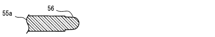
さらに、端板53は、複数のリブ55を有する。リブ55は、板状である。複数のリブ55は、放射状に配置されている。複数のリブ55は、周方向に互いに離れて配置されている。複数のリブ55の間には、径方向に延びる複数の通路が区画形成されている。複数のリブ55は、巻き始めのリブ55aと巻き終わりのリブ55bとを含む8本のリブによって提供されている。複数のリブ55は、コア54の一部でもある。
Further, the
端板53は、複数の支持部56を有する。複数の支持部56は、複数のリブ55の径方向外側の縁に分散的に配置されている。支持部56は、径方向外側に向けて突出している突部である。複数の支持部56は、軸方向に関して互いに離れて配置されている。複数の支持部56は、周方向に関して互いに離れて配置されている。支持部56の径方向外側面は、曲面である。支持部56の径方向外側面は、繊維層61の内面に接触している。複数の支持部56は、繊維層61を受け止め、支持する接触面を提供する。
The
フレーム51の径方向外側には、繊維層61が配置されている。繊維層61は、筒状である。繊維層61は、複数のリブ55に対応して、やや多面筒状である。繊維層61は、内周面と、外周面と、両端面とを有している。内周面は、燃料の入口面を提供する。外周面は、燃料の出口面を提供する。両端面は、端板52、53に押し付けられている。両端面は、シール面を提供する。
A
繊維層61は、流れ方向に沿って複数の層を有する。複数の層は、互いに直接的に接触している。それぞれの層は、同じ繊維によって形成されている。繊維層61は、帯状の素材62によって形成されている。帯状の素材62は、長尺の母材を所定の長さに切断することによって、または四角い母材から切り取ることによって得ることができる。よって、母材から円板を切り出す場合に比べて、材料の無駄が抑制される。素材62は、不織布である。素材62は、綿状と呼べるものである。素材62は、フィルタ31の材料よりも遥かに低い繊維密度を有している。素材62は、フレーム51に巻くことができる柔らかさを有している。
The
繊維層61は、コア54の上に配置されている。繊維層61は、コア54の径方向外側に配置されている。素材62は、螺旋状、または渦巻状と呼びうる形状である。繊維層61は、帯状の素材62の筒状ロール体を含む。繊維層61は、ロール体だけで提供することができる。繊維層61は、一連の帯状の素材62の積層体によって提供されている。繊維層61は、素材62のロール体に加えて、追加的な層を備えていてもよい。
The
素材62は、コア54の上において積層されている。素材62は、径方向に関して少なくとも部分的に2層以上に重なるように配置されている。素材62は、径方向に関して2層以上に重なるように2周以上に配置されている。素材62は、3層となるように3周以上に配置されている。2層以上に積層された素材62は、燃料の通過方向に沿って厚い繊維層61を形成することを可能とする。
The
素材62は、コア54が提供する仮想の周面に沿って配置されている。素材62は、コア54を2周以上にわたって周回している。素材62は、コア54を3周以上にわたって周回していてもよい。繊維層61の中において積層された2つの隣接層は、直接的に接触している。この構成は、厚い繊維層61を形成することを可能とする。
The
素材62は、端部63と、端部64とを有する。内側の端部63は、巻き始め端である。外側の端部64は、巻き終わり端である。端部63と端部64とは、周方向に隣接する2つのリブ55a、55bの間に配置されている。素材62は、2つのリブ55a、55bの間において、内側層から外側層へのシフト部を有している。シフト部は、素材62が段差状に曲がる部分である。複数のシフト部が、2つのリブ55a、55bの間に集中的に配置されている。この配置は、繊維層61の外周面を円形に近づけることを可能とする。
The
フレーム51と繊維層61とは、複数の接合部71において接合されている。接合部71は、繊維層61の内面または外面においてドット状である。言い換えると、繊維層61を径方向外側から見て、接合部71は、ドット状である。接合部71は、フレーム51の材料を溶融させ、繊維層61の中に浸透させ、再び硬化させた再硬化部分である。接合部71において、フレーム51と繊維層61とは分離不能に接合されている。
The
複数の接合部71は、繊維層61の筒状の周面において分散して配置されている。複数の接合部71は、均一に分散している。複数の接合部71は、軸方向および周方向に関して分散している。
The plurality of
図3に図示されるように、複数の接合部71は、軸方向に関して互いに離れて設けられた複数の接合部71を含む。図中には、軸方向に沿って配置された4つの接合部71が図示されている。図4に図示されるように、複数の接合部71は、周方向に関して互いに離れて設けられた複数の接合部71を含む。図中には、周方向に沿って配置された8つの接合部71が図示されている。複数の接合部71は、軸方向および周方向に関して等間隔に配置されている。図示の例では、複数の接合部71は、4×8=32の水玉模様(Polkadots Pattern)のように配置されている。
As illustrated in FIG. 3, the plurality of
複数の接合部71は、最も内側の層(最も内側の素材62)とフレーム51とを接合している。接合部71は、少なくともひとつの層とフレーム51とを接合している。複数の接合部71は、複数のリブ55の先端に配置されている。
The plurality of
図4に図示されるように、複数の接合部71は、接合部71aと、接合部71bとを有する。接合部71aは、フレーム51から径方向に関して最初の層をなす素材62を、フレーム51に接合する。接合部71aは、隣接接合部とも呼ばれる。接合部71aは、一方の端部63の近傍において素材62をフレーム51に接合している。接合部71aは、最も内側の層とフレーム51とを接合する。接合部71aは、燃料の流れの最も上流に位置する層をフレーム51に固定している。最初の層の上には、複数の接合部71aが設けられている。
As illustrated in FIG. 4, the plurality of
接合部71bは、フレーム51から少なくともひとつの介在層を隔てて配置された最後の層をなす素材62を、介在層を通してフレーム51に接合する。接合部71bは、貫通接合部とも呼ばれる。接合部71bは、他方の端部64の近傍において素材62をフレーム51に接合している。接合部71bは、最も外側の層とフレーム51とを接合する。接合部71bは、最も外側の層とフレーム51とを接合している。接合部71bは、燃料の流れの最も下流に位置する層をフレーム51に固定している。接合部71bは、素材62の巻き終わりの端部64の近傍にだけ設けられている。
The joining portion 71b joins the material 62 that is the last layer disposed at least one intervening layer away from the
接合部71bは、複数の層とフレーム51とを接合していてもよい。例えば、接合部71bは、すべての層とフレーム51とを接合する場合がある。接合部71bは、複数の層をフレーム51に固定している。接合部71bは、繊維層61の厚さ方向に関して繊維層61の全体をフレーム51に固定している。言い換えると、接合部71bは、繊維層61をフレーム51に縫い留めている。接合部71bは、素材62の3層分を、フレーム51に接合している。
The joining portion 71b may join the plurality of layers and the
接合部71aは、巻き始めのリブ55aに設けられている。接合部71aは、最初の接合位置である。接合部71bは、巻き終わりのリブ55bの上に設けられている。接合部71bは、重複部分を形成する巻き付けの後の最後の接合位置である。
The joining portion 71a is provided on the
複数の接合部71は、周方向、軸方向、および径方向に関して、素材62をフレーム51に固定している。端部63と接合部71aとの間の延び出し片は、自らの剛性によって図示される形状を維持する。端部64と接合部71bとの間の延び出し片は、自らの剛性によって図示される形状を維持する。これら延び出し片は、燃料が流れるとき、すなわち通常の使用状態の下でも、図示されるように隣接する層に接する形状を維持する。
The plurality of
繊維層61の内周面または外周面に沿って分散している複数の接合部71は、確実な固定に貢献する。また、再硬化部分である接合部71は、確実な固定を提供する。複数の接合部71aは、燃料の流れの上流側からの繊維層61の圧潰を抑制する。接合部71bは、燃料の流れの下流側への繊維層61の分離を抑制する。繊維層61は、端面において平面52b、53bに接触だけでシールを提供している。このため、接着剤の厚さに依存することなく、安定的なシールが得られる。この結果、確実な繊維層61の固定と、シール性とが実現される。この構造は、コストの抑制を可能とする。
The plurality of
図2に図示されるように、係合部22a、51aはケース連結部を提供している。ケース連結部は、ケース6からフィルタ31を外した状態においても、水凝集器32がケース6との連結状態を維持可能に形成されている。交換作業は、連結機構23を緩める段階と、キャップ21からカップ22を外す段階とを有する。連結機構23においてキャップ21とカップ22とを分離させる操作は、回転操作である。ケース連結部による水凝集器32とカップ22との連結状態は、回転操作とは異なる操作によって解除可能である。ケース連結部は、樹脂材料を弾性変形させながら、水凝集器32を軸方向へ引き抜く軸方向操作、またはやや斜めに引き抜く軸方向操作によって、解除状態となる。よって、連結機構23のための操作によって、ケース連結部における連結状態が解除されることはない。
As shown in FIG. 2, the engaging
さらに、交換作業は、カップ22内からフィルタ31を引き抜く段階と、カップ22内から水凝集器32を引き抜く段階と、それらを交換し、再び組み立てる段階とを有する。フィルタ31が軸方向へ引き抜かれるとき、ケース連結部は、係合状態を維持し、水凝集器32とカップ22との連結状態を維持する。よって、フィルタ31がカップ22内から抜かれても、水凝集器32はカップ22内に残される。これによりフィルタ31のみの交換が促進される。なお、カップ22内はダーティサイドDSであり、繊維層61の上流と下流もダーティサイドDSである。よって、連結管46が引き抜かれた後に、新品のフィルタ31が差し込まれても、クリーンサイドCSへの異物の進入は抑制される。
Further, the replacement operation includes a step of pulling out the
連結管46と、筒状部分52aとは、フィルタ31と水凝集器32とを機械的に連結する連結部である。さらに、連結管46と、筒状部分52aとは、繊維層61に燃料を流すように燃料通路の流体的な連結を提供する流体的連結部でもある。ケース連結部は、流体的連結部における連結が解除された状態でも、ケース6との連結状態を維持可能に形成されている。
The connecting
<製造方法>
燃料フィルタ装置2の製造方法は、ケース6を形成する工程と、ケース6の中にフィルタユニット7を配置する工程と、ケース6を閉じる工程とを含む。フィルタユニット7の製造方法は、フィルタ31を組み立てる工程と、水凝集器32を組み立てる工程と、フィルタ31と水凝集器32とを連結する工程とを含む。
<Production method>
The method of manufacturing the
フィルタユニット7を交換する方法は、ケース6を開く工程と、古いフィルタユニット7を取り出す工程と、新しいフィルタユニット7を配置する工程と、ケース6を閉じる工程とを含む。フィルタ31だけが交換される場合、古いフィルタユニット7をフィルタ31と水凝集器32とに分解する工程と、古い水凝集器32を新しいフィルタ31に連結して新しいフィルタユニット7を製造する工程とが追加される。分解工程は、水凝集器32とカップ22との連結状態を維持したまま、フィルタ31と水凝集器32とを分離させる段階を含むことができる。分解工程は、ケース6の中で、ケース6を開く工程において同時に実行することができる。連結する工程は、水凝集器32とカップ22との連結状態を維持したまま、ケース6の中で実行することができる。連結する工程は、ケース6を閉じる工程において同時に実行することができる。
The method of replacing the
水凝集器32の製造方法は、フレーム51を形成する形成工程と、フレーム51に繊維層61を装着する装着工程と、フレーム51に繊維層61を固定する固定工程とを含む。形成工程は、樹脂材料によってフレーム51を成形する工程を含むことができる。装着工程は、フレーム51に沿って素材62を巻く巻き工程によって提供することができる。装着工程は、素材62を巻いた繊維層61の中に、フレーム51を装着する工程によって提供されてもよい。この実施形態では、装着工程は、巻き工程によって提供されている。
The method of manufacturing the
装着工程は、燃料が繊維層61を通過するように繊維層61とフレーム51との間にシールを形成する段階を含む。シールは、筒状の繊維層61の端面を平面52b、53bに押し付けることによって形成されている。シールは、巻き工程において、素材62の長手方向端面を、平面52b、53bに押し付けることによって形成される。巻き工程において、素材62は、長手方向端面を平面52b、53bに押し付けながら、フレーム51に巻き付けられる。
The mounting step includes forming a seal between the
巻き工程は、素材62をフレーム51の上に巻き付ける工程である。巻き工程は、リブ55aの上を巻き始めとして開始される。素材62は、端部63から巻き付けられる。巻き工程は、端部64が図示される規定の位置に位置付けられると終了する。
The winding step is a step of winding the
巻き工程は、素材62を少なくとも部分的に2層以上に重なるように巻く工程である。巻き工程は、素材62をフレーム51の上に一周だけ巻き付ける第1段階を含む。これにより、素材62の一周目が形成される。巻き工程は、素材62をフレーム51の上に、追加的に一周だけ巻き付ける第2段階を含む。これにより、素材62の二周目が形成される。巻き工程は、素材62をフレーム51の上に、さらに追加的に一周だけ巻き付ける第3段階を含む。これにより、素材62の三周目が形成される。この結果、繊維層61が形成される。
The winding step is a step of winding the material 62 so as to at least partially overlap two or more layers. The winding step includes a first step of winding the
巻き工程は、リブ55aの先端に素材62を位置付ける初期段階を含む。初期段階では、端部63が、最初のリブ55aと最後のリブ55bとの間に位置づけられる。初期段階では、さらに、リブ55aの先端の上に、素材62が位置付けられる。初期段階では、リブ55aを越えて、素材62が配置される。初期段階において、素材62は、2番目のリブ55の上にまで配置されてもよい。初期段階の後に、上述の第1段階、第2段階、および第3段階が実行される。
The winding process includes an initial stage of positioning the
巻き工程は、フレーム51から少なくともひとつの介在層を隔てて最後の層を配置する工程を有する。この工程は、第3段階によって提供される。介在層は、第1層、および第2層によって提供されている。
The winding step includes a step of disposing the last layer with at least one intervening layer separated from the
固定工程は、複数の接合部71を形成することによって繊維層61をフレーム51に固定する。固定工程は、巻き工程の中で間欠的に実行される。固定工程は、複数の接合部71のそれぞれを形成するための複数の段階を含む。固定工程は、リブ55aの上に素材62が位置付けられた後に、最初の接合部71aを形成するための初期段階を含むことができる。固定工程は、2番目以降のリブ55の上に素材62が位置付けられた後に、接合部71aを形成するための中間段階を含むことができる。
In the fixing step, the
中間段階は、複数のリブ55の上に素材62を位置付けた後に、複数の接合部71aを順に形成するように実行されてもよい。中間段階は、ひとつのリブ55の上に素材62を位置付けた後に、ひとつの接合部71を形成する単段階を、複数のリブ55の上において繰り返すように実行されてもよい。また、中間段階は、複数の部分段階に分割されて実行されてもよい。ひとつの部分段階では、一群の複数のリブ55、例えば3つのリブ55に対して、素材62を配置した後に、それら複数のリブ55の上に複数の接合部71aが形成される。残る部分段階では、残る一群のリブ55、例えば3つのリブ55に対して、素材62を配置した後に、それらリブ55の上に複数の接合部71aが形成される。
The intermediate stage may be performed such that after positioning the
図5は、最初のリブ55aを示す。支持部56がリブ55aの先端に形成されている。溶融前において、支持部56はやや大きい。リブ55aとは、素材62の単層分を固定する溶融樹脂を供給できる体積を与えられている。
FIG. 5 shows the
図6は、リブ55aの先端に素材62が位置付けられた状態を示す。巻き工程において、素材62は、リブ55aの上に位置付けられる。
FIG. 6 shows a state in which the
固定工程は、リブ55aの一部を溶融させる段階を含む。固定工程は、素材62を押える工程を含む。リブ55aの一部は、高温の部材57を押し当てることにより溶融する。素材62は、部材57により押され、圧縮される。リブ55aの一部は、外側から供給される高エネルギーにより、例えば、レーザの照射、超音波の照射、電磁波の照射、熱風の供給などによって溶融させることができる。リブ55aの一部は、溶融段階の間に、図6に図示される形状から変形する。この段階は、流動性のある材料をフレーム51と素材62との間に供給する供給段階である。材料は、素材62の中に浸透する程度の流動性を与えられている。
The fixing step includes a step of melting a part of the
固定工程は、溶融した樹脂材料の中に素材62の繊維を位置づける段階を含む。この段階では、溶融した樹脂材料が、繊維層に浸透しながら広がる。また、一部の繊維は、溶融した樹脂材料の中に進入する。この段階は、流動性のある材料と、素材62とを混在させる段階である。
The fixing step includes positioning the fibers of the
固定工程は、一旦溶融した樹脂材料を再硬化させる段階を含む。この段階は、流動性のある材料の流動性を低下させる段階である。材料の流動性は、素材62をフレーム51に固定する程度の低い水準に低下する。
The fixing step includes a step of re-curing the resin material once melted. In this step, the fluidity of the fluid material is reduced. The fluidity of the material is reduced to a level low enough to fix the
図7は、接合部71の一例を示す。接合部71は、再硬化した樹脂の塊である。接合部71は、樹脂の塊の内部に、素材62の繊維を取り込んでいる。接合部71の形状は、リブ55aとは異なる。リブ55aの形状は、接合部71の不定形な塊状に変化している。接合部71の表面は、流動に伴って不定形な表面を与えられている。接合部71の形状は、支持部56の先端から径方向外側へ延び出す棒状、または柱状とも呼ぶことができる。さらに、素材62は、接合部71が再硬化するときの収縮により、またはリブ55aを溶融させるために外から与えられた押圧力により、やや凹むように変形する場合がある。例えば、素材62の厚さは、接合部71の周辺においてやや減少する場合がある。
FIG. 7 shows an example of the joint 71. The
上述のように、巻き工程の第1段階により、フレーム51の上には、素材62の最内層が配置される。固定工程により、複数の接合部71aが形成される。この固定工程は、径方向における最初の層だけをフレーム51に接合する隣接接合工程を提供する。この結果、素材62の最内層、すなわち最上流層は、フレーム51に強固に固定される。さらに、巻き工程が、第1段階、第2段階、第3段階と進められる。巻き工程の段階が進行する度に、素材62が最後のリブ55bの上に積層的に配置される。
As described above, the innermost layer of the
図8は、最後のリブ55bを示す。支持部56がリブ55bの先端に形成されている。リブ55bは、素材62の3層分を固定する溶融樹脂を供給できる体積を与えられている。フレーム51は、そこに留められる素材62の層数、またはそこに留められる繊維層の厚さに対応している。巻き終わりのリブ55bの上に、第3層の素材62が位置付けられると、固定工程の最後の部分段階が実行される。最後の部分段階では、最後のリブ55bが溶融され、再硬化される。
FIG. 8 shows the
図9は、巻き終わりのリブ55bの上における接合部71bの一例を示す。固定工程により、リブ55bは、複数の層をなしている素材62の少なくとも最も外側の層と接合されるように溶融される。リブ55bは、複数の層と接合されるように溶融される。リブ55bは、すべての層と接合されるように溶融される。接合部71bは、複数の層からなる繊維層61を固定する。接合部71bは、繊維層61を縫い留めているともいえる。3層の素材62は部材57により大きく圧縮され、凹部66を形成している。この工程は、径方向における最後の層を介在層を通してフレーム51に接合する貫通接合工程を提供する。
FIG. 9 shows an example of the joint portion 71b on the
ひとつのリブ55の上には、軸方向に沿って複数の支持部56が設けられている。例えば、最初のリブ55aの上には、軸方向に沿って複数の支持部56が設けられている。例えば、最後のリブ55bの上には、軸方向に沿って複数の支持部56bが設けられている。よって、リブ55aの上には、軸方向に沿って複数の接合部71aが形成されている。リブ55bの上には、複数の最後の接合部71bが形成されている。これら複数の最後の接合部71bは、素材62の巻き終わりの端部64をフレーム51に固定する。端部64は、最下流側に位置しているから、接合部71bは、繊維層61の厚さ方向の全体をフレーム51の上に固定している。
A plurality of
図10は、接合部71bの変形例を示す。リブ55bから接合部71bが形成されるとき、リブ55bの周囲には、厚い3層の素材62が積層されている。接合部71bは、3層の素材62を完全に貫通しなくてもよい。
FIG. 10 shows a modification of the joint 71b. When the joint portion 71b is formed from the
<作動>
図2に戻り、図中には、燃料の流れが矢印によって例示されている。入口11から供給された燃料は、水凝集器32を通過した後に、フィルタ31を通り、出口12から出る。水凝集器32から流出した水滴は、自らの重さによって沈降し、カップ22内に沈んでゆく。一方、燃料は、カップ22内を上に向けて流れ、フィルタ31に流入する。フィルタ31を通過した燃料は、出口12へ到達する。
<Operation>
Returning to FIG. 2, the flow of fuel is illustrated by arrows in the figure. The fuel supplied from the
カップ22内に沈んだ水滴は、カップ22の底部に溜まる。図中には、水滴WDと、水と燃料との境界である水面WLとが模式的に図示されている。水面WLの上昇によってフロート27が浮き上がると、水位センサ26が検出信号を出力する。検出信号は、利用者に警報を与える。利用者がドレンプラグ25を緩めると、水が排出される。
The water drops sinking into the
フィルタ31は、燃料フィルタ装置2に意図された大きさの固形の異物を除去する性能を与えられている。フィルタ31は、高圧ポンプなどが長期間にわたって性能を維持できるように、微細な固形異物を除去できるように設計されている。一方、水凝集器32に設けられた繊維層61は、上記意図された固形の異物を除去することができない。繊維層61は、フィルタ31より大きい孔を有するからである。繊維層61は、水分を捕捉し、凝集させるために設計されている。
The
燃料は、繊維層61の内面から外面に向けて流れる。接合部71aは、燃料の圧力に抗して繊維層61の内周面を、規定の位置に位置付ける。接合部71bは、燃料の圧力に抗して、繊維層61の外周面、例えば端部64を、規定の位置に位置づける。よって、燃料が繊維層61内を通過しても、繊維層61の圧潰、および分解が抑制される。
The fuel flows from the inner surface to the outer surface of the
燃料の中に含まれる水分は、繊維層61の中で、繊維層61に捕捉され、凝集し、大きい水滴に成長する。水滴は、繊維層61の外面から、再び燃料の中に放たれる。
The water contained in the fuel is captured by the
<効果>
以上に述べた実施形態によると、それぞれ独立して利用可能な複数の特徴的な構成によって、複数の利点が提供される。繊維層61は、厚い凝集層を有する水凝集器32、および燃料フィルタ装置2を提供する。繊維層61は、2周以上に周回した帯状の素材62の筒状ロール体によって提供されている。このため、取り扱いやすい帯状の素材62によって厚い繊維層61が形成される。この結果、製造が容易な厚い凝集層を有する水凝集器32、水凝集器32を含むフィルタユニット7、および燃料フィルタ装置2が提供される。
<Effect>
According to the embodiments described above, a plurality of advantages are provided by a plurality of characteristic configurations which can be used independently. The
繊維層61は、複数の接合部71によってフレーム51に固定されている。複数の接合部71は、確実な固定を提供する。しかも、複数の接合部71は、分散配置されている。複数の接合部71は、繊維層61の繊維と一体化している。このため、確実な固定が可能である。
The
複数の接合部71は、繊維層61の内周面において繊維層61をフレーム51に固定する接合部71aと、繊維層61の外周面において繊維層61をフレーム51に固定する接合部71bとを有する。接合部71bは、貫通接合部を提供する。貫通接合部は、最後の層をなす素材を、介在層を通してフレーム51に接合する。貫通接合部は、厚い繊維層61を維持しながら、最後の層の位置を固定する。よって、燃料の流れに起因する繊維層61の破損が抑制される。
The plurality of
繊維層61は、内周面と外周面との両方においてフレーム51に固定される。接合部71aは、繊維層61の内周面からの圧潰を抑制する。接合部71bは、繊維層61の外周面からの分離を抑制する。言い換えると、接合部71aは、燃料の流れの上流側からの繊維層61の圧潰を抑制する。接合部71bは、燃料の流れの下流側への繊維層61の分離を抑制する。これにより、少ない部品点数で厚い凝集層を固定できる水凝集器32、水凝集器32を含むフィルタユニット7、および燃料フィルタ装置2が提供される。
The
水凝集器32の製造方法によると、帯状の素材が少なくとも部分的に2層以上に重なるように巻かれる。最後の層は、フレーム51から少なくともひとつの介在層を隔てて配置される。接合工程では、最後の層をなす素材が、介在層を通してフレーム51に接合される。この方法によると、繊維層61を巻き工程によって製造することができる。しかも、接合工程により、繊維層61が確実にフレームに固定される。接合工程では、最後の層の位置を維持しながら、繊維層61がフレーム51に固定される。よって、厚い繊維層61が維持される。
According to the method of manufacturing the
第2実施形態
この実施形態は、先行する実施形態を基礎的形態とする変形例である。上記実施形態では、ダーティサイドDSに水凝集器32が配置されている。これに代えて、水凝集器は、クリーンサイドCSに配置されてもよい。
Second Embodiment This embodiment is a modified example based on the preceding embodiment. In the above embodiment, the
図11および図12に図示されるように、燃料フィルタ装置2は、固形の異物を除去するためのフィルタ231を有する。フィルタ231は、ケース6内をダーティサイドDSとクリーンサイドCSとに区画している。フィルタ231は、プリーツ形状の円筒状濾材を有する。フィルタ231は、ダーティサイドDSとクリーンサイドCSとの直接的な連通を阻止するためのOリングなどのシール部材を有する。
As shown in FIGS. 11 and 12, the
水凝集器232は、クリーンサイドCSに配置されている。言い換えると、水凝集器232は、フィルタ231の下流に配置されている。水凝集器232は、フィルタ231の径方向内側に配置されている。水凝集器232は、フレーム51と、フレーム51に固定された繊維層61とを有する。繊維層61は、複数の接合部71によってフレーム51に固定されている。繊維層61は、水凝集層を提供する。水凝集器232は、係合部22a、51aによってカップ22に連結されている。この実施形態でも、係合部22a、51aは、水凝集器232の再利用を促す。
The water flocculator 232 is arranged on the clean side CS. In other words, the
この実施形態では、燃料は、筒状の繊維層61の外周面から内周面へ向けて径方向へ流れる。繊維層61は、内側のフレーム51によって支持されているから、燃料の流れに伴う圧力は、繊維層61を圧縮するように作用する。一方で、フレーム51から繊維層61の厚さ方向に延びる複数の接合部71は、繊維層61の厚さを維持するように作用する。よって、この実施形態でも、厚い繊維層61が維持される。
In this embodiment, the fuel flows radially from the outer peripheral surface to the inner peripheral surface of the
燃料フィルタ装置2は、水分離層233を有する。水分離層233は、水凝集器232の下流側に配置されている。水分離層233は、水凝集器232と出口12との間に配置されている。水凝集器232と水分離層233との間には、水滴を沈降させるための円筒状の空洞が区画形成されている。水分離層233は、水滴の通過を抑制し、水滴の沈降を促進する。水分離層233は、撥水性、または疎水性と呼びうる性質をもつスクリーンによって提供されている。
The
水分離層233は、連結機構234によって水凝集器232に連結されている。連結機構234は、スナップフィット機構によって提供されている。連結機構234は、水分離層233を水凝集器232に連結した状態を維持しながら、フィルタ231だけを取り出すことを可能とする。よって、連結機構234は、水分離層233の再利用を促す。
The
第3実施形態
この実施形態は、先行する実施形態を基礎的形態とする変形例である。上記実施形態では、水分離層233は、水凝集器232に連結されている。これに代えて、水分離層は、フィルタ231に連結されていてもよい。
Third Embodiment This embodiment is a modified example based on the preceding embodiment. In the above embodiment, the
図13に図示されるように、水分離層333は、連結機構334によってフィルタ231に連結されている。この構成によると、水凝集器232の再利用が促される。一方、フィルタ231と水分離層333との交換が促される。
As shown in FIG. 13, the
第4実施形態
この実施形態は、先行する実施形態を基礎的形態とする変形例である。上記実施形態では、水分離層233は、フィルタ231または水凝集器232に連結されている。これに代えて、水分離層は、独立していてもよい。
Fourth Embodiment This embodiment is a modified example based on the preceding embodiment. In the above embodiment, the
図14に図示されるように、水分離層433は、連結機構を持たない。この構成では、水分離層433は、自重によって水凝集器232の上に残される。ただし、利用者は、水分離層433を水凝集器232から容易に取り外すことができる。よって、水分離層433の交換、再利用の選択を利用者に委ねることができる。
As shown in FIG. 14, the
第5実施形態
この実施形態は、先行する実施形態を基礎的形態とする変形例である。上記実施形態では、フレーム51の外側に素材62が巻かれている。これに代えて、素材62は、フレーム51の内側に巻かれてもよい。
Fifth Embodiment This embodiment is a modified example based on the preceding embodiment. In the above embodiment, the
図15に図示されるように、水凝集器532は、フレーム51を有する。水凝集器532は、先行する実施形態の水凝集器32、232として利用可能である。フレーム51は、径方向内側に向けて突出する複数のリブ55を有する。フレーム51は、繊維層61の径方向外側に配置されている。複数の支持部56は、繊維層61の外周面に隣接している。
As shown in FIG. 15, the
帯状の素材62は、複数のリブ55が区画形成する仮想の筒状空洞の中に、内側から巻き付けられている。製造方法において、帯状の素材62は、端部63からフレーム51の内部空洞の中に順に配置されてゆく。端部64は、端部63の位置を越えて更に巻き重ねた位置に位置付けられている。帯状の素材62は、径方向外側から径方向内側へ重ねられている。この実施形態でも、製造方法において、帯状の素材62は、縫い付けられる。この実施形態でも、巻き重ねられた帯状の素材62によって厚い繊維層61が形成されている。
The belt-shaped
繊維層61は、複数の接合部71によってフレーム51に固定されている。繊維層61は、最初のリブ55および支持部56の上に、接合部71aによって固定されている。接合部71aは、素材62の1枚に相当するひとつの層を固定する。言い換えると、接合部71aは、最も外側の層を固定する。さらに別の観点では、接合部71aは、燃料流れにおいて最も上流の層を固定する。水凝集器532は、最初の層を固定するための複数の接合部71aを有する。これら複数の接合部71aは、周方向に関して分散して配置されている。
The
繊維層61は、最後のリブ55の上に、接合部71bによって固定されている。接合部71bは、素材62の複数枚に相当する複数の層を固定する。言い換えると、接合部71bは、最も内側の層を固定する。さらに別の観点では、接合部71bは、燃料流れの最も下流の層を固定する。水凝集器532は、最後の層を固定するための複数の接合部71bを有する。これら複数の接合部71bは、周方向に関して分散して配置されている。
The
繊維層61は、いくつかのリブ55の上に、接合部71cによって固定されている。接合部71cは、複数の層を固定する。接合部71cによって固定される層の数は、接合部71aが固定する層の数と、接合部71bが固定する層の数との間にある。図示の例では、接合部71bは、2つの層を固定する。言い換えると、接合部71cは、燃料流れ中間の層を固定する。水凝集器532は、複数の接合部71cを有する。これら複数の接合部71cは、周方向に関して分散して配置されている。複数の接合部71cは、中間の接合部とも呼ばれる。複数の接合部71cは、厚い繊維層61を、その内部において補強する。
The
複数の接合部71aは、繊維層61の径方向外側において、繊維層61をフレーム51に確実に固定する。複数の接合部71aは、繊維層61の径方向外側から内側への圧潰を抑制する。複数の接合部71bは、繊維層61の径方向内側において、繊維層61をフレーム51に確実に固定する。複数の接合部71bは、繊維層61の内周面、言い換えると最下流層の径方向内側への分解を抑制する。
The plurality of joints 71 a securely fix the
この実施形態でも、厚い繊維層61を取り扱いやすい帯状の素材62によって形成することができる。この実施形態でも、複数の接合部71によって、厚い繊維層61が確実にフレーム51に固定される。さらに、複数の接合部71aは、燃料の流れの上流側からの繊維層61の圧潰を抑制する。複数の接合部71bは、燃料の流れの下流側への繊維層61の分離を抑制する。
Also in this embodiment, the
他の実施形態
この明細書における開示は、例示された実施形態に制限されない。開示は、例示された実施形態と、それらに基づく当業者による変形態様を包含する。例えば、開示は、実施形態において示された部品および/または要素の組み合わせに限定されない。開示は、多様な組み合わせによって実施可能である。開示は、実施形態に追加可能な追加的な部分をもつことができる。開示は、実施形態の部品および/または要素が省略されたものを包含する。開示は、ひとつの実施形態と他の実施形態との間における部品および/または要素の置き換え、または組み合わせを包含する。開示される技術的範囲は、実施形態の記載に限定されない。開示されるいくつかの技術的範囲は、請求の範囲の記載によって示され、さらに請求の範囲の記載と均等の意味及び範囲内での全ての変更を含むものと解されるべきである。
Other Embodiments The disclosure herein is not limited to the illustrated embodiments. The disclosure includes the illustrated embodiments and variations thereon based on those skilled in the art. For example, the disclosure is not limited to the combination of parts and / or elements shown in the embodiments. The disclosure can be implemented in various combinations. The disclosure may have additional parts that can be added to the embodiments. The disclosure encompasses embodiments that omit parts and / or elements. The disclosure encompasses the replacement or combination of parts and / or elements between one embodiment and another. The disclosed technical scope is not limited to the description of the embodiments. Some of the disclosed technical ranges are indicated by the description of the claims, and should be construed to include all modifications within the meaning and scope equivalent to the description of the claims.
上記実施形態では、低圧ポンプの下流に燃料フィルタ装置2が設置される正圧システムが例示されている。これに代えて、低圧ポンプの上流に燃料フィルタ装置2が設置される負圧システムが適用対象とされてもよい。上記実施形態では、フィルタ31は、ハニカム型のエレメント42を有する。これに代えて、菊花型、渦巻き型など多様な形式の濾材を用いることができる。
In the above embodiment, the positive pressure system in which the
上記実施形態では、ケース6は、キャップ21とカップ22とに2分割可能である。これに代えて、ケース6は、3分割可能に構成されてもよい。また、フタに相当する部材だけが分離可能に構成されてもよい。いずれの構成においても、フィルタユニット7は交換可能にケース6内に収容される。
In the above embodiment, the
上記実施形態では、水凝集器は、放射状のリブ55をもつ星形のフレーム51を有する。これに代えて、水凝集器は、カゴ型、コイル型など多様な形状のフレームを利用することができる。また、フレーム51は、繊維層61の両端面との接触を確実化するために、平面52b、53bに代えて、同心状の段差面、複数の突部など多様な表面形状を有することができる。また、上記実施形態では、水凝集器の径方向外側面に繊維層61の外周面が露出している。これに代えて、繊維層61の外周面よりされに外側に、網状、柱状の保護部材が設けられていてもよい。また、上記実施形態では、1層の素材62または3層の素材を通してリブ55を溶融させている。これに代えて、リブ55a、55bに、素材62を刺すためのニードルを設けても良い。ニードルによって、素材62の固定が可能である。
In the above embodiment, the water aggregator has a star-shaped
上記実施形態では、帯状の素材62を数周巻くことによって繊維層61を形成している。これに代えて、必要な厚さの繊維層61が得られるように、帯状の素材62の巻回数は、1周以上に設定することができる。
In the above embodiment, the
上記実施形態では、フレーム51を形成する樹脂材料を溶融させることにより、接合部71を形成している。これに代えて、繊維層61を形成する繊維が溶融可能な場合には、繊維層61を溶融させることによって接合部71を形成してもよい。また、フレーム51と繊維層61との間に流動状態の接着剤を供給し、硬化させることによって接合部71を形成してもよい。これに場合でも、複数の接合部71によって、燃料の流れ、圧力差に耐えうる確実な固定を提供できる。
In the above embodiment, the joining
上記実施形態では、帯状の素材62の第1層と複数のリブ55との間に接合部71aを設け、帯状の素材62の第3層とリブ55bとの間に接合部71bを設けている。これに代えて、最初の接合部71aと、最後の接合部71bとだけを設けてもよい。また、複数の接合部71aのうちの一部だけを設けてもよい。また、複数の接合部71aの一部を、接合部71bと同様の複数層にわたる接合部としてもよい。
In the above-described embodiment, the joining portion 71a is provided between the first layer of the strip-shaped
上記実施形態では、繊維層61の両端面と平面52b、53bとを接触させることによりシールを提供している。これに代えて、フレーム51と繊維層61とを接着してシールを提供してもよい。例えば、フレーム51と繊維層61との間に接着剤を配置してもよい。例えば、フレーム51と繊維層61との間に、フレーム51を形成する樹脂材料を溶融させ再硬化させた溶着部分を設けてもよい。
In the above embodiment, the seal is provided by bringing both end surfaces of the
上記実施形態では、係合部22a、51aが提供する連結部は、スナップフィットである。これに代えて、ねじを利用した連結が提供されてもよい。さらに、水凝集器32とカップ22とを永久的に連結してもよい。例えば、水凝集器32のフレーム51とカップ22とを溶着、または接着してもよい。上記実施形態では、連結管46および筒状部分52aが提供する連結部は、筒と管との差し込み関係によって提供されるシール性能を有する流体的な連結である。これに代えて、Oリング、リップシールなどのシール部材が設けられてもよい。また、ねじによる連結が併用されてもよい。さらに、端面と端面との軸方向への押し当て、または2つの部材の圧入によって提供されてもよい。
In the above embodiment, the connection provided by the
1 燃料供給装置、2 燃料フィルタ装置、3 燃料タンク、4 内燃機関、
6 ケース、7 フィルタユニット、11 入口、12 出口、
13 入口通路、14 出口通路、21 キャップ、22 カップ、
22a 係合部、23 連結機構、
24 ドレン穴、25 ドレンプラグ、26 水位センサ、27 フロート、
28 サポート柱、31、231 フィルタ、32、232、532 水凝集器、
233、333、433 水分離層、 234、334 連結機構、
41 フレーム、42 エレメント、43 カバー部材、44 接続部分、
45 センタパイプ、46 連結管、47 開口、
51 フレーム、51a 係合部、52、53 端板、52a 筒状部分、
52b 平面、53a 円錐部、53b 平面、53c 下向き壁、
54 コア、55、55a、55b リブ、56 支持部、57 高温の部材、
61 繊維層、62 素材、63、64 端部、
71、71a、71b 接合部、
DS ダーティサイド、CS クリーンサイド、WD 水滴、WL 水面。
1 fuel supply device, 2 fuel filter device, 3 fuel tank, 4 internal combustion engine,
6 cases, 7 filter units, 11 inlets, 12 outlets,
13 inlet passage, 14 outlet passage, 21 caps, 22 cups,
22a engaging portion, 23 connecting mechanism,
24 drain holes, 25 drain plugs, 26 water level sensor, 27 float,
28 support pillar, 31, 231 filter, 32, 232, 532 water aggregator,
233, 333, 433 water separation layer, 234, 334 connection mechanism,
41 frame, 42 elements, 43 cover member, 44 connection part,
45 center pipe, 46 connecting pipe, 47 opening,
51 frame, 51a engaging portion, 52, 53 end plate, 52a cylindrical portion,
52b plane, 53a cone, 53b plane, 53c downward wall,
54 core, 55, 55a, 55b rib, 56 support, 57 high temperature member,
61 fiber layer, 62 material, 63, 64 end,
71, 71a, 71b joint,
DS dirty side, CS clean side, WD water drop, WL water surface.
Claims (13)
前記フレームに装着され、前記燃料の中の水を凝集させる筒状の繊維層であって、前記径方向に関して2層以上に重なるように2周以上に配置された帯状の素材(62)のロール体を含む繊維層(61)、および
前記繊維層を前記フレームに固定する複数の接合部(71)を備え、
複数の前記接合部は、前記繊維層の筒状の周面において分散して配置されている水凝集器。 A frame (51) that allows fuel flow in the radial direction,
A roll of a band-shaped material (62) attached to the frame and arranged in two or more turns so as to overlap two or more layers in the radial direction, the roll being a tubular fiber layer for coagulating water in the fuel. A fiber layer (61) including a body, and a plurality of joints (71) for fixing the fiber layer to the frame ;
The plurality of the joints, water condenser that are dispersedly arranged in the cylindrical circumferential surface of the fibrous layer.
前記フレームに装着され、前記燃料の中の水を凝集させる筒状の繊維層であって、前記径方向に関して少なくとも部分的に2層以上に重なるように配置された帯状の素材(62)のロール体を含む繊維層(61)、および
前記繊維層を前記フレームに固定する複数の接合部(71)を備え、
複数の前記接合部は、前記フレームから少なくともひとつの介在層を隔てて配置された最後の層をなす前記素材を、前記介在層を通して前記フレームに接合する貫通接合部(71b)を有する水凝集器。 A frame (51) that allows fuel flow in the radial direction,
A roll of a band-shaped material (62) mounted on the frame and being a tubular fiber layer for coagulating water in the fuel and arranged so as to at least partially overlap two or more layers in the radial direction. A fiber layer (61) including a body, and a plurality of joints (71) for fixing the fiber layer to the frame;
The plurality of joints have a through-coupling part (71b) for joining the material, which is the last layer disposed at least one intervening layer from the frame, to the frame through the intervening layer. .
前記フレームから前記径方向に関して最初の層をなす前記素材を、前記フレームに接合する隣接接合部(71a)を有する請求項2または請求項3に記載の水凝集器。 The plurality of joints further include:
The water flocculator according to claim 2 or 3, further comprising an adjacent joint (71a) for joining the material forming the first layer in the radial direction from the frame to the frame.
前記隣接接合部(71a)は、前記一方の端部(63)の近傍において前記素材を前記フレームに接合しており、
前記貫通接合部(71b)は、前記他方の端部(64)の近傍において前記素材を前記フレームに接合している請求項4に記載の水凝集器。 The material has one end (63) and the other end (64) in the longitudinal direction,
The adjacent joint (71a) joins the material to the frame near the one end (63),
The water agglomerator according to claim 4, wherein the through joint (71b) joins the material to the frame near the other end (64).
複数の前記接合部のそれぞれは、複数の前記支持部のそれぞれに設けられている請求項1から請求項5のいずれかに記載の水凝集器。 The frame is disposed radially inward or radially outward of the fiber layer, and has a plurality of support portions (56) adjacent to an inner peripheral surface or an outer peripheral surface of the fiber layer,
The water coagulator according to any one of claims 1 to 5, wherein each of the plurality of joining portions is provided on each of the plurality of support portions.
前記繊維層は、前記平面に接触しているだけの両端面を有する請求項1から請求項7のいずれかに記載の水凝集器。 The frame has planes (52b, 53b) facing both end faces of the fiber layer,
The water flocculator according to any one of claims 1 to 7, wherein the fiber layer has both end faces only in contact with the plane.
前記燃料から固形の異物を除去するフィルタ(31、231)と、
燃料の通路を区画形成するとともに、前記水凝集器と前記フィルタとを収容するケース(6)とを備える燃料フィルタ装置。 A water coagulator (32, 232, 532) according to any one of claims 1 to 8,
Filters (31, 231) for removing solid foreign matter from the fuel;
A fuel filter device including a case (6) that defines a fuel passage and houses the water aggregator and the filter.
前記フレームの内側または外側において、燃料の中の水を凝集させる帯状の素材(62)を少なくとも部分的に2層以上に重なるように巻くことにより、前記素材のロール体を形成する巻き工程、および
前記繊維層を前記フレームに接合する接合工程を備え、
前記巻き工程は、前記フレームから少なくともひとつの介在層を隔てて最後の層を配置する工程を有し、
前記接合工程は、前記最後の層をなす前記素材を、前記介在層を通して前記フレームに接合する工程を有する水凝集器の製造方法。 In a method for manufacturing a water aggregator, comprising: a frame (51) allowing a flow of fuel in a radial direction; and a tubular fiber layer for aggregating water in the fuel,
A winding step of forming a roll body of the material by winding a band-shaped material (62) that agglomerates water in the fuel at least partially on two or more layers inside or outside the frame; A joining step of joining the fiber layer to the frame,
The winding step includes a step of arranging a last layer with at least one intervening layer separated from the frame,
The method for manufacturing a water aggregator, wherein the joining step includes a step of joining the material forming the last layer to the frame through the intervening layer.
前記径方向における最初の層だけを前記フレームに接合する隣接接合工程、および
前記径方向における最後の層を前記介在層を通して前記フレームに接合する貫通接合工程を有する請求項11に記載の水凝集器の製造方法。 The joining step includes:
The water flocculator according to claim 11, further comprising: an adjacent joining step of joining only the first layer in the radial direction to the frame; and a through joining step of joining the last layer in the radial direction to the frame through the intervening layer. Manufacturing method.
前記巻き工程において、前記素材は、長手方向に沿って延びる長手端面を前記平面に接触させながら巻かれる請求項11または請求項12に記載の水凝集器の製造方法。 Furthermore, the method further includes a step of forming flat surfaces (52b, 53b) on the frame, which face both end surfaces of the fiber layer,
The method according to claim 11, wherein, in the winding step, the material is wound while a longitudinal end surface extending along a longitudinal direction is in contact with the plane.
Priority Applications (3)
| Application Number | Priority Date | Filing Date | Title |
|---|---|---|---|
| JP2016133710A JP6658361B2 (en) | 2016-07-05 | 2016-07-05 | Water coagulator, fuel filter device, and method of manufacturing water coagulator |
| CN201780041715.3A CN109416006B (en) | 2016-07-05 | 2017-06-09 | Moisture collector, fuel filter device, and method for manufacturing moisture collector |
| PCT/JP2017/021413 WO2018008327A1 (en) | 2016-07-05 | 2017-06-09 | Water flocculator, fuel filter device, and method for manufacturing water flocculator |
Applications Claiming Priority (1)
| Application Number | Priority Date | Filing Date | Title |
|---|---|---|---|
| JP2016133710A JP6658361B2 (en) | 2016-07-05 | 2016-07-05 | Water coagulator, fuel filter device, and method of manufacturing water coagulator |
Publications (3)
| Publication Number | Publication Date |
|---|---|
| JP2018003757A JP2018003757A (en) | 2018-01-11 |
| JP2018003757A5 JP2018003757A5 (en) | 2019-01-24 |
| JP6658361B2 true JP6658361B2 (en) | 2020-03-04 |
Family
ID=60948808
Family Applications (1)
| Application Number | Title | Priority Date | Filing Date |
|---|---|---|---|
| JP2016133710A Active JP6658361B2 (en) | 2016-07-05 | 2016-07-05 | Water coagulator, fuel filter device, and method of manufacturing water coagulator |
Country Status (1)
| Country | Link |
|---|---|
| JP (1) | JP6658361B2 (en) |
Families Citing this family (1)
| Publication number | Priority date | Publication date | Assignee | Title |
|---|---|---|---|---|
| US10753330B2 (en) * | 2018-04-23 | 2020-08-25 | Caterpillar Inc. | Fuel-water separator self-draining valve with release member |
Family Cites Families (8)
| Publication number | Priority date | Publication date | Assignee | Title |
|---|---|---|---|---|
| JPS3622682Y1 (en) * | 1959-12-10 | 1961-08-30 | ||
| JPS5979203U (en) * | 1982-11-17 | 1984-05-29 | 和興産業株式会社 | Coalescing element for water separation |
| JP2009127610A (en) * | 2007-11-28 | 2009-06-11 | Wako Filter Technology Kk | Fuel filter |
| JP5565328B2 (en) * | 2011-01-25 | 2014-08-06 | 株式会社デンソー | Fuel filter |
| JP5510430B2 (en) * | 2011-11-04 | 2014-06-04 | 株式会社デンソー | Fuel filter device |
| DE102011120647A1 (en) * | 2011-12-09 | 2013-06-13 | Mann + Hummel Gmbh | Fuel filter of an internal combustion engine and filter element of a fuel filter |
| JP5841006B2 (en) * | 2012-05-24 | 2016-01-06 | 株式会社日本自動車部品総合研究所 | Fuel filtration device |
| JP6102673B2 (en) * | 2013-10-21 | 2017-03-29 | 京三電機株式会社 | Diesel fuel filter device |
-
2016
- 2016-07-05 JP JP2016133710A patent/JP6658361B2/en active Active
Also Published As
| Publication number | Publication date |
|---|---|
| JP2018003757A (en) | 2018-01-11 |
Similar Documents
| Publication | Publication Date | Title |
|---|---|---|
| US20140284268A1 (en) | Filter Element of a Fuel Filter and Method for Producing such a Filter Element | |
| US9718005B2 (en) | Fuel filter of an internal combustion engine, and filter element of a fuel filter | |
| US8137546B2 (en) | Fuel filter device | |
| US7901572B2 (en) | Fuel filter apparatus | |
| RU2383382C2 (en) | Filter cart | |
| CN103975156B (en) | The fuel filter of internal combustion engine and the filter cell of fuel filter | |
| JP6102673B2 (en) | Diesel fuel filter device | |
| US9999848B2 (en) | Dual bag filter | |
| JP2013522002A (en) | Filter medium of filter element, filter element, and method of manufacturing filter medium | |
| JP2013532249A (en) | Improved filters for internal combustion engines | |
| US7073670B2 (en) | High capacity depth filter bag | |
| DK161805B (en) | FOLDED, MULTIPLE LAYER EXISTING FILTER UNIT | |
| JP6658361B2 (en) | Water coagulator, fuel filter device, and method of manufacturing water coagulator | |
| WO2018008327A1 (en) | Water flocculator, fuel filter device, and method for manufacturing water flocculator | |
| JP2009127610A (en) | Fuel filter | |
| KR20200035028A (en) | Tank filter system including liquid filter and liquid filter | |
| CN103573493B (en) | Fuel filter | |
| EP0876185A1 (en) | A filter cartridge and method | |
| JP2018003758A (en) | Water condenser and fuel filter device | |
| JP5350936B2 (en) | Coalescer cartridge | |
| JP2004195418A (en) | Liquid-liquid separating filter | |
| JP2010084752A (en) | Filter for fuel | |
| JP5745392B2 (en) | Internal filtration device | |
| JP2015029946A (en) | Filter unit | |
| WO2017030010A1 (en) | Fuel filter and element |
Legal Events
| Date | Code | Title | Description |
|---|---|---|---|
| A521 | Request for written amendment filed |
Free format text: JAPANESE INTERMEDIATE CODE: A523 Effective date: 20181207 |
|
| A621 | Written request for application examination |
Free format text: JAPANESE INTERMEDIATE CODE: A621 Effective date: 20181207 |
|
| TRDD | Decision of grant or rejection written | ||
| A01 | Written decision to grant a patent or to grant a registration (utility model) |
Free format text: JAPANESE INTERMEDIATE CODE: A01 Effective date: 20200107 |
|
| A61 | First payment of annual fees (during grant procedure) |
Free format text: JAPANESE INTERMEDIATE CODE: A61 Effective date: 20200120 |
|
| R150 | Certificate of patent or registration of utility model |
Ref document number: 6658361 Country of ref document: JP Free format text: JAPANESE INTERMEDIATE CODE: R150 |
|
| R250 | Receipt of annual fees |
Free format text: JAPANESE INTERMEDIATE CODE: R250 |
|
| R250 | Receipt of annual fees |
Free format text: JAPANESE INTERMEDIATE CODE: R250 |