JP6654066B2 - Medical observation device - Google Patents
Medical observation device Download PDFInfo
- Publication number
- JP6654066B2 JP6654066B2 JP2016048906A JP2016048906A JP6654066B2 JP 6654066 B2 JP6654066 B2 JP 6654066B2 JP 2016048906 A JP2016048906 A JP 2016048906A JP 2016048906 A JP2016048906 A JP 2016048906A JP 6654066 B2 JP6654066 B2 JP 6654066B2
- Authority
- JP
- Japan
- Prior art keywords
- gears
- motor
- control
- support member
- unit
- Prior art date
- Legal status (The legal status is an assumption and is not a legal conclusion. Google has not performed a legal analysis and makes no representation as to the accuracy of the status listed.)
- Active
Links
Images


Classifications
-
- A—HUMAN NECESSITIES
- A61—MEDICAL OR VETERINARY SCIENCE; HYGIENE
- A61B—DIAGNOSIS; SURGERY; IDENTIFICATION
- A61B90/00—Instruments, implements or accessories specially adapted for surgery or diagnosis and not covered by any of the groups A61B1/00 - A61B50/00, e.g. for luxation treatment or for protecting wound edges
- A61B90/36—Image-producing devices or illumination devices not otherwise provided for
- A61B90/37—Surgical systems with images on a monitor during operation
-
- A—HUMAN NECESSITIES
- A61—MEDICAL OR VETERINARY SCIENCE; HYGIENE
- A61B—DIAGNOSIS; SURGERY; IDENTIFICATION
- A61B90/00—Instruments, implements or accessories specially adapted for surgery or diagnosis and not covered by any of the groups A61B1/00 - A61B50/00, e.g. for luxation treatment or for protecting wound edges
- A61B90/20—Surgical microscopes characterised by non-optical aspects
- A61B90/25—Supports therefor
-
- A—HUMAN NECESSITIES
- A61—MEDICAL OR VETERINARY SCIENCE; HYGIENE
- A61B—DIAGNOSIS; SURGERY; IDENTIFICATION
- A61B90/00—Instruments, implements or accessories specially adapted for surgery or diagnosis and not covered by any of the groups A61B1/00 - A61B50/00, e.g. for luxation treatment or for protecting wound edges
- A61B90/36—Image-producing devices or illumination devices not otherwise provided for
- A61B90/361—Image-producing devices, e.g. surgical cameras
-
- B—PERFORMING OPERATIONS; TRANSPORTING
- B25—HAND TOOLS; PORTABLE POWER-DRIVEN TOOLS; MANIPULATORS
- B25J—MANIPULATORS; CHAMBERS PROVIDED WITH MANIPULATION DEVICES
- B25J9/00—Programme-controlled manipulators
- B25J9/16—Programme controls
- B25J9/1615—Programme controls characterised by special kind of manipulator, e.g. planar, scara, gantry, cantilever, space, closed chain, passive/active joints and tendon driven manipulators
- B25J9/162—Mobile manipulator, movable base with manipulator arm mounted on it
-
- B—PERFORMING OPERATIONS; TRANSPORTING
- B25—HAND TOOLS; PORTABLE POWER-DRIVEN TOOLS; MANIPULATORS
- B25J—MANIPULATORS; CHAMBERS PROVIDED WITH MANIPULATION DEVICES
- B25J9/00—Programme-controlled manipulators
- B25J9/16—Programme controls
- B25J9/1679—Programme controls characterised by the tasks executed
- B25J9/1689—Teleoperation
-
- G—PHYSICS
- G05—CONTROLLING; REGULATING
- G05B—CONTROL OR REGULATING SYSTEMS IN GENERAL; FUNCTIONAL ELEMENTS OF SUCH SYSTEMS; MONITORING OR TESTING ARRANGEMENTS FOR SUCH SYSTEMS OR ELEMENTS
- G05B2219/00—Program-control systems
- G05B2219/30—Nc systems
- G05B2219/41—Servomotor, servo controller till figures
- G05B2219/41032—Backlash
-
- G—PHYSICS
- G05—CONTROLLING; REGULATING
- G05B—CONTROL OR REGULATING SYSTEMS IN GENERAL; FUNCTIONAL ELEMENTS OF SUCH SYSTEMS; MONITORING OR TESTING ARRANGEMENTS FOR SUCH SYSTEMS OR ELEMENTS
- G05B2219/00—Program-control systems
- G05B2219/30—Nc systems
- G05B2219/41—Servomotor, servo controller till figures
- G05B2219/41265—To avoid backlash
-
- Y—GENERAL TAGGING OF NEW TECHNOLOGICAL DEVELOPMENTS; GENERAL TAGGING OF CROSS-SECTIONAL TECHNOLOGIES SPANNING OVER SEVERAL SECTIONS OF THE IPC; TECHNICAL SUBJECTS COVERED BY FORMER USPC CROSS-REFERENCE ART COLLECTIONS [XRACs] AND DIGESTS
- Y10—TECHNICAL SUBJECTS COVERED BY FORMER USPC
- Y10S—TECHNICAL SUBJECTS COVERED BY FORMER USPC CROSS-REFERENCE ART COLLECTIONS [XRACs] AND DIGESTS
- Y10S901/00—Robots
- Y10S901/27—Arm part
- Y10S901/28—Joint
-
- Y—GENERAL TAGGING OF NEW TECHNOLOGICAL DEVELOPMENTS; GENERAL TAGGING OF CROSS-SECTIONAL TECHNOLOGIES SPANNING OVER SEVERAL SECTIONS OF THE IPC; TECHNICAL SUBJECTS COVERED BY FORMER USPC CROSS-REFERENCE ART COLLECTIONS [XRACs] AND DIGESTS
- Y10—TECHNICAL SUBJECTS COVERED BY FORMER USPC
- Y10S—TECHNICAL SUBJECTS COVERED BY FORMER USPC CROSS-REFERENCE ART COLLECTIONS [XRACs] AND DIGESTS
- Y10S901/00—Robots
- Y10S901/30—End effector
- Y10S901/44—End effector inspection
-
- Y—GENERAL TAGGING OF NEW TECHNOLOGICAL DEVELOPMENTS; GENERAL TAGGING OF CROSS-SECTIONAL TECHNOLOGIES SPANNING OVER SEVERAL SECTIONS OF THE IPC; TECHNICAL SUBJECTS COVERED BY FORMER USPC CROSS-REFERENCE ART COLLECTIONS [XRACs] AND DIGESTS
- Y10—TECHNICAL SUBJECTS COVERED BY FORMER USPC
- Y10S—TECHNICAL SUBJECTS COVERED BY FORMER USPC CROSS-REFERENCE ART COLLECTIONS [XRACs] AND DIGESTS
- Y10S901/00—Robots
- Y10S901/46—Sensing device
- Y10S901/47—Optical
Landscapes
- Health & Medical Sciences (AREA)
- Engineering & Computer Science (AREA)
- Surgery (AREA)
- Life Sciences & Earth Sciences (AREA)
- General Health & Medical Sciences (AREA)
- Nuclear Medicine, Radiotherapy & Molecular Imaging (AREA)
- Public Health (AREA)
- Heart & Thoracic Surgery (AREA)
- Veterinary Medicine (AREA)
- Medical Informatics (AREA)
- Molecular Biology (AREA)
- Animal Behavior & Ethology (AREA)
- Oral & Maxillofacial Surgery (AREA)
- Pathology (AREA)
- Biomedical Technology (AREA)
- Robotics (AREA)
- Mechanical Engineering (AREA)
- Orthopedic Medicine & Surgery (AREA)
- Radiology & Medical Imaging (AREA)
- Gynecology & Obstetrics (AREA)
- Microscoopes, Condenser (AREA)
- Manipulator (AREA)
- Gear Transmission (AREA)
- Transmission Devices (AREA)
Description
本発明は、医療用観察装置に関する。 The present invention relates to a medical observation device.
従来、医療分野において、患者の術部の微小部位を拡大観察するための拡大光学系と、複数のアーム部、及び当該複数のアーム部を回動可能に接続する複数の関節部を有し、先端で拡大光学系を支持する支持部とを備えた医療用観察装置が知られている(例えば、特許文献1参照)。
特許文献1に記載の医療用観察装置は、関節部に動力を与え、当該関節部にて接続された2つのアーム部を相対的に回動させるモータと、互いに噛合する2つの歯車を有し、モータから当該関節部への動力伝達経路に設けられる歯車機構とを備える。そして、特許文献1に記載の医療用観察装置では、術者によるフットスイッチへの操作に応じて、モータが駆動し、当該モータからの動力が歯車機構を介して関節部に与えられる。これにより、当該関節部にて接続された2つのアーム部が相対的に回動し、拡大光学系の位置及び姿勢が変更される(視野が移動する)。
Conventionally, in the medical field, it has a magnifying optical system for magnifying and observing a micro site of a surgical site of a patient, a plurality of arms, and a plurality of joints rotatably connecting the plurality of arms, 2. Description of the Related Art There is known a medical observation device including a support portion that supports a magnifying optical system at a distal end (for example, see Patent Document 1).
The medical observation device described in Patent Literature 1 has a motor that supplies power to a joint and relatively rotates two arms connected by the joint, and two gears that mesh with each other. And a gear mechanism provided on a power transmission path from the motor to the joint. In the medical observation device described in Patent Literature 1, a motor is driven in response to an operation on a foot switch by an operator, and power from the motor is applied to a joint via a gear mechanism. As a result, the two arms connected by the joint rotate relatively, and the position and orientation of the magnifying optical system are changed (the field of view moves).
ところで、互いに噛合する2つの歯車には、寸法公差や、温度変化による線膨張を考慮して、所謂バックラッシが設けられている。
そして、このようにバックラッシが存在している場合には、以下の問題がある。
先ず、術者は、フットスイッチに操作を行い、モータを第1方向に回転(以下、順回転と記載)させ、拡大光学系の位置及び姿勢を変更する。このように動作が行われた場合には、2つの歯車において、モータの順回転に応じて互いに噛合しない側の各第1歯面間の第1距離は当該2つの歯車のバックラッシ量と同一の値となる。一方、モータの順回転に応じて互いに噛合する側の各第2歯面間の第2距離は0となる。
次に、術者は、フットスイッチに操作を行い、モータを第1方向とは逆方向に回転(以下、逆回転と記載)させる。この場合には、モータの逆回転に応じて互いに噛合する側の各第1歯面間の第1距離が2つの歯車のバックラッシ量と同一の値となっているため、当該第1距離が0となるまで(当該第1距離を詰めるまで)、2つの歯車は互いに噛合しない(空走する)。すなわち、拡大光学系の位置及び姿勢は変更されない。そして、当該第1距離が0となり、2つの歯車が互いに噛合してから、拡大光学系の位置及び姿勢が変更されることとなる。
以上のように、直前に動作した回転方向とは逆方向にモータを回転させる場合には、2つの歯車のバックラッシ量に応じた空走期間が存在し、視野移動を迅速に行うことができない、という問題がある。
By the way, the two gears meshing with each other are provided with a so-called backlash in consideration of dimensional tolerance and linear expansion due to temperature change.
When such backlash exists, there is the following problem.
First, the surgeon operates the foot switch to rotate the motor in the first direction (hereinafter referred to as forward rotation) to change the position and orientation of the magnifying optical system. When the operation is performed in this manner, in the two gears, the first distance between the first tooth surfaces on the side that does not mesh with each other in accordance with the forward rotation of the motor is equal to the backlash amount of the two gears. Value. On the other hand, the second distance between the second tooth surfaces on the side meshing with each other according to the forward rotation of the motor is zero.
Next, the operator operates the foot switch to rotate the motor in a direction opposite to the first direction (hereinafter, referred to as reverse rotation). In this case, the first distance between the first tooth surfaces on the side meshing with each other in response to the reverse rotation of the motor has the same value as the backlash amount of the two gears. The two gears do not mesh with each other (run idle) until the following is satisfied (until the first distance is reduced). That is, the position and orientation of the magnifying optical system are not changed. Then, after the first distance becomes 0 and the two gears mesh with each other, the position and orientation of the magnifying optical system are changed.
As described above, when the motor is rotated in a direction opposite to the rotation direction that was operated immediately before, there is an idle running period corresponding to the backlash amount of the two gears, and it is not possible to quickly move the visual field. There is a problem.
本発明は、上記に鑑みてなされたものであって、迅速に視野移動を行うことができる医療用観察装置を提供することを目的とする。 The present invention has been made in view of the above, and an object of the present invention is to provide a medical observation device capable of quickly moving a visual field.
上述した課題を解決し、目的を達成するために、本発明に係る医療用観察装置は、観察対象を拡大して撮像可能な撮像部と、複数のアーム部、及び当該複数のアーム部を互いに回動可能に接続する複数の関節部を有し、先端で前記撮像部を支持する支持部と、前記支持部に設けられ、前記複数の関節部の少なくとも一つの関節部に動力を与え、当該関節部にて接続された2つの前記アーム部を相対的に回動させるモータと、互いに噛合する2つの歯車を有し、前記モータから前記少なくとも一つの関節部への動力伝達経路に設けられる歯車機構と、ユーザ操作を受け付ける操作受付部と、前記操作受付部が受け付けた前記ユーザ操作に応じて前記モータを動作させる第1制御を実行するとともに、当該第1制御を完了して当該モータの動作を停止させた後、第2制御を実行する制御部とを備え、前記動力伝達経路には、前記歯車機構と前記少なくとも一つの関節部との間に、当該歯車機構から当該少なくとも一つの関節部への動力の伝達を遮断した遮断状態、または当該伝達を許容した許容状態に切り替える状態切替部が設けられ、前記支持部は、前記撮像部の位置及び姿勢を固定する固定モードと、ユーザによる当該支持部への手動操作に応じて前記撮像部の位置及び姿勢を調整可能とするオールフリーモードと、前記操作受付部が受け付けた前記ユーザ操作に応じて前記撮像部による撮像視野を移動させる移動動作モードとのいずれかの動作モードで動作し、前記制御部は、前記移動動作モードにおいて、前記第1制御及び前記第2制御を実行し、前記第2制御を実行することで、前記第1制御時での前記モータの回転方向とは逆方向に当該モータを回転させ、前記2つの歯車において、当該逆方向への当該モータの回転に応じて互いに噛合する側の各第1歯面間の第1距離と、噛合しない側の各第2歯面間の第2距離とを当該2つの歯車のバックラッシ量よりもそれぞれ小さくするとともに、前記オールフリーモードにおいて、前記状態切替部を前記遮断状態に設定することを特徴とする。 In order to solve the above-described problem and achieve the object, a medical observation apparatus according to the present invention includes an imaging unit capable of enlarging an object to be observed and capturing an image, a plurality of arms, and the plurality of arms. A plurality of joints that are rotatably connected, a support that supports the imaging unit at the tip, and a power supply that is provided on the support and provides power to at least one joint of the plurality of joints. A motor for relatively rotating the two arms connected by a joint, and two gears meshing with each other, and a gear provided on a power transmission path from the motor to the at least one joint; A mechanism, an operation receiving unit that receives a user operation, and a first control for operating the motor in accordance with the user operation received by the operation receiving unit, and completing the first control to operate the motor. To After sealed, and a control unit for executing a second control, the said power transmission path, between the gear mechanism and the at least one joint portion, from the gear mechanism the at least one into the joint portion A state switching unit that switches to a cut-off state in which the transmission of the power is interrupted, or a permissible state in which the transmission is allowed, the support unit includes a fixed mode for fixing the position and orientation of the imaging unit; An all-free mode in which the position and orientation of the imaging unit can be adjusted in accordance with a manual operation on the unit, and a movement operation mode in which the imaging field of view of the imaging unit is moved in accordance with the user operation received by the operation reception unit It operates in one mode of operation and the control unit, in the mobile mode of operation, and executes the first control and the second control, performing the second control Rotating the motor in a direction opposite to the rotation direction of the motor at the time of the first control, and in the two gears, the first gears on the side that mesh with each other according to the rotation of the motor in the opposite direction. a first distance between the tooth surface and a second distance between the second tooth surface on the side not mesh with smaller respectively than the backlash of the two gears in the all free mode, the state switching unit It is characterized in that it is set to the cutoff state .
また、本発明に係る医療用観察装置は、上記発明において、前記制御部は、前記第2制御を実行することで、前記第1距離と前記第2距離とを前記バックラッシ量の半分の値にすることを特徴とする。 Further, in the medical observation device according to the present invention, in the above invention, the control unit executes the second control to reduce the first distance and the second distance to a half value of the backlash amount. It is characterized by doing.
また、本発明に係る医療用観察装置は、上記発明において、前記制御部は、前記第2制御の後に前記第1制御を実行する際、前記第2距離が0になるまで第1回転速度で前記モータを回転させ、当該0になった後に当該第1回転速度よりも低い第2回転速度で当該モータを回転させることを特徴とする。 Further, the medical observation apparatus according to the present invention, in the above invention, the control unit, the time of executing the first control after the second control, the first rotational speed before Symbol second distance becomes 0 And rotating the motor at a second rotation speed lower than the first rotation speed after the rotation becomes zero.
また、本発明に係る医療用観察装置は、上記発明において、前記制御部は、前記遮断状態において、前記第1回転速度で前記モータを回転させ、前記許容状態において、前記第2回転速度で前記モータを回転させることを特徴とする。 Further, the medical observation apparatus according to the present invention, in the above invention, before Symbol controller, in the blocking state, said rotates the motor at a first rotation speed, in the allowable state, in the second rotational speed The motor is rotated.
また、本発明に係る医療用観察装置は、上記発明において、前記2つの歯車の一方の歯車を回転可能に軸支する第1支持部材と、前記第1支持部材とは別体で構成され、前記2つの歯車の他方の歯車を回転可能に軸支する第2支持部材とを備え、前記第1支持部材及び前記第2支持部材は、互いに接続することで、前記2つの歯車を互いに噛合させ、前記第1支持部材は、前記第2支持部材に対して移動可能とし、当該第2支持部材に対して移動することで前記2つの歯車のバックラッシ量を変更可能とすることを特徴とする。 Further, the medical observation device according to the present invention, in the above invention, a first support member rotatably supporting one of the two gears, and the first support member is configured as a separate body, A second support member that rotatably supports the other gear of the two gears, wherein the first support member and the second support member are connected to each other so that the two gears mesh with each other. The first support member is movable with respect to the second support member, and by moving with respect to the second support member, the backlash amount of the two gears can be changed.
また、本発明に係る医療用観察装置は、上記発明において、前記2つの歯車は、平歯車でそれぞれ構成され、前記第1支持部材は、前記第2支持部材に対して回転可能とし、当該第2支持部材に対して回転することで前記2つの歯車のバックラッシ量を変更可能とし、前記第1支持部材の回転軸は、前記2つの歯車の各回転軸とは独立し、当該各回転軸にそれぞれ平行となる軸であることを特徴とする。 Further, in the medical observation device according to the present invention, in the above invention, the two gears are each configured by a spur gear, and the first support member is rotatable with respect to the second support member. By rotating with respect to the two support members, the backlash amount of the two gears can be changed, and the rotation axis of the first support member is independent of each rotation axis of the two gears, and It is characterized in that the axes are parallel to each other.
また、本発明に係る医療用観察装置は、上記発明において、前記歯車機構は、前記2つの歯車を含む3つ以上の歯車を有し、前記モータの回転を減速する減速機構であり、前記2つの歯車は、前記減速機構における互いに噛合する複数組の歯車のうち、減速比が最も大きい組の歯車であることを特徴とする。 Further, in the medical observation device according to the present invention, in the above invention, the gear mechanism has three or more gears including the two gears, and is a reduction mechanism that reduces the rotation of the motor. The one gear is a set of gears having the largest reduction ratio among a plurality of sets of gears meshing with each other in the reduction mechanism.
本発明に係る医療用観察装置では、制御部は、操作受付部へのユーザ操作に応じてモータを動作させる第1制御を実行するとともに、当該第1制御を完了して当該モータの動作を停止させた後、上述した第1,第2距離を2つの歯車のバックラッシ量よりも小さくする第2制御を実行する。すなわち、第1制御によって、第1距離が2つの歯車のバックラッシ量と同一の値となり、第2距離が0となっていたところ、当該第1制御の後に第2制御を実行することで、第1,第2距離を2つの歯車のバックラッシ量よりも小さくする。
このため、第1,第2制御を実行した後に、操作受付部にユーザ操作がなされ、当該第1制御時での回転方向とは逆方向にモータを回転させる第1制御を実行する場合には、2つの歯車のバックラッシ量よりも小さい第1距離だけ詰めれば、2つの歯車を互いに噛合させ、モータの回転を関節部に伝達する(撮像部の位置及び姿勢を変更する(視野移動を行う))ことができる。
したがって、本発明に係る医療用観察装置によれば、直前に実行した第1制御時での回転方向とは逆方向にモータを回転させる第1制御を実行する場合において、2つの歯車の空走期間を短縮し、視野移動を迅速に行うことができる、という効果を奏する。
In the medical observation device according to the present invention, the control unit executes the first control for operating the motor in accordance with the user operation on the operation reception unit, and completes the first control to stop the operation of the motor. After that, the second control is executed to make the first and second distances smaller than the backlash amount of the two gears. That is, by the first control, the first distance becomes the same value as the backlash amount of the two gears, and the second distance becomes 0. By executing the second control after the first control, the first distance is obtained. First, the second distance is made smaller than the backlash amount of the two gears.
Therefore, when the user operation is performed on the operation receiving unit after executing the first and second controls and the first control for rotating the motor in a direction opposite to the rotation direction in the first control is performed. If the first gear is reduced by a first distance smaller than the backlash amount of the two gears, the two gears mesh with each other, and the rotation of the motor is transmitted to the joint (changes the position and orientation of the imaging unit (performs the visual field movement)). )be able to.
Therefore, according to the medical observation apparatus of the present invention, in the case where the first control for rotating the motor in the direction opposite to the rotation direction at the time of the first control executed immediately before is executed, the idle running of the two gears is performed. There is an effect that the period can be shortened and the visual field can be moved quickly.
以下に、図面を参照して、本発明を実施するための形態(以下、実施の形態)について説明する。なお、以下に説明する実施の形態によって本発明が限定されるものではない。さらに、図面の記載において、同一の部分には同一の符号を付している。 Hereinafter, an embodiment (hereinafter, an embodiment) for carrying out the present invention will be described with reference to the drawings. The present invention is not limited by the embodiments described below. Further, in the description of the drawings, the same portions are denoted by the same reference numerals.
〔医療用観察システムの概略構成〕
図1は、本発明の実施の形態に係る医療用観察システム1の概略構成を示す図である。
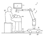
医療用観察システム1は、手術時や検査時において術者が処置する対象となる部位(観察対象)を拡大して撮像し、当該撮像に応じた画像を表示するシステムである。この医療用観察システム1は、図1に示すように、観察対象を撮像して画像信号を出力する医療用観察装置2と、医療用観察装置2から出力された画像信号に基づく画像を表示する表示装置3とを備える。
[Schematic configuration of medical observation system]
FIG. 1 is a diagram showing a schematic configuration of a medical observation system 1 according to an embodiment of the present invention.
The medical observation system 1 is a system that magnifies and captures a part (observation target) to be treated by an operator during an operation or an examination and displays an image corresponding to the imaging. As shown in FIG. 1, the medical observation system 1 displays a medical observation device 2 that captures an observation target and outputs an image signal, and an image based on the image signal output from the medical observation device 2. And a
医療用観察装置2は、図1に示すように、顕微鏡部21と、ベース部22と、支持部23と、制御部24と、フットスイッチ25とを備える。
顕微鏡部21は、観察対象を拡大して撮像し、当該撮像に応じた画像信号を出力する。この顕微鏡部21は、例えば、各種の公知の光学系と、当該光学系が集光した光を受光して電気信号に変換するCCD(Charge Coupled Device)センサやCMOS(Complementary Metal-Oxide-Semiconductor)センサ等の各種の公知の撮像素子とを備える。また、この顕微鏡部21には、AF(Auto Focus)機能や光学ズーム機能等の各種の機能も搭載されている。また、顕微鏡部21としては、一対の撮像素子を備えた所謂、ステレオカメラとして構成しても構わない。
ベース部22は、医療用観察装置2の基台であり、キャスター221(図1)を介して床面上を移動可能に構成されている。
As shown in FIG. 1, the medical observation device 2 includes a
The
The
支持部23は、ベース部22から延在し、先端(ベース部22から離間した端部)にて顕微鏡部21を保持する。そして、支持部23は、術者の操作に応じて、顕微鏡部21を3次元的に移動可能とする。
なお、本実施の形態では、支持部23は、顕微鏡部21の移動に対して6自由度を有するように構成されているが、これに限られず、その他の異なる数の自由度を有するように構成しても構わない。
The
In the present embodiment, the
この支持部23は、図1に示すように、第1〜第5アーム部231A〜231Eと、第1〜第6関節部232A〜232Fとを備える。
なお、第1〜第6関節部232A〜232Fは、具体的な図示を省略したが、固定部と、可動部と、固定部及び可動部に介装されるベアリングとをそれぞれ有し、ベアリングを介し、固定部に対して可動部が回転可能な構造になっている。
As shown in FIG. 1, the
The first to sixth
第1関節部232Aは、支持部23の先端に位置し、円筒形状を有する。この第1関節部232Aは、円筒内側に位置する可動部(図示略)にて顕微鏡部21を保持し、円筒外側に位置する固定部(図示略)にて第1アーム部231Aに支持される。そして、第1関節部232Aにおいて、可動部は、ベアリング(図示略)を介し、固定部に対して、第1軸O1を中心として回転可能とする。このため、第1関節部232Aは、第1軸O1まわりに顕微鏡部21を回転可能とする。
ここで、第1軸O1は、第1関節部232Aにおける円筒の中心軸であり、第1関節部232Aに保持された顕微鏡部21の光軸に一致する軸である。
すなわち、第1軸O1まわりに顕微鏡部21を回転させると、顕微鏡部21による撮像視野の向きが変更される。
The first
Here, the first axis O1 is the central axis of the cylinder in the first joint 232A, and is the axis that coincides with the optical axis of the
That is, when the
第1アーム部231Aは、第1関節部232Aの側面から第1軸O1と直交する方向に延在し、先端にて第1関節部232A(固定部)を支持する。
第2関節部232Bは、先端側に位置する可動部(図示略)にて第1アーム部231Aの基端に接続し、基端側(ベース部22に近接する側)に位置する固定部(図示略)にて第2アーム部231Bに接続する。そして、第2関節部232Bにおいて、可動部は、ベアリング(図示略)を介し、固定部に対して、第2軸O2を中心として回転可能とする。このため、第2関節部232Bは、第2軸O2まわりに第1アーム部231A(顕微鏡部21)を回転可能とする。
ここで、第2軸O2は、第1軸O1に直交し、第1アーム部231Aの延在方向に平行な軸である。
すなわち、第2軸O2まわりに顕微鏡部21を回転させると、観察対象に対する顕微鏡部21の光軸の向きが変更される。言い換えれば、顕微鏡部21による撮像視野がX軸方向(図1)に移動する。このため、第2関節部232Bは、顕微鏡部21による撮像視野をX軸方向(+X軸方向または−X軸方向)に移動させる関節部である。
The
The second
Here, the second axis O2 is an axis orthogonal to the first axis O1 and parallel to the extending direction of the
That is, when the
第2アーム部231Bは、第1,第2軸O1,O2に直交する方向に延在し、先端にて第2関節部232B(固定部)を支持する。
第3関節部232Cは、先端側に位置する可動部(図示略)にて第2アーム部231Bの基端に接続し、基端側に位置する固定部(図示略)にて第3アーム部231Cに接続する。そして、第3関節部232Cにおいて、可動部は、ベアリング(図示略)を介し、固定部に対して、第3軸O3を中心として回転可能とする。このため、第3関節部232Cは、第3軸O3まわりに第2アーム部231B(顕微鏡部21)を回転可能とする。
ここで、第3軸O3は、第1,第2軸O1,O2に直交(第2アーム部231Bの延在方向に平行)する軸である。
すなわち、第3軸O3まわりに顕微鏡部21を回転させると、観察対象に対する顕微鏡部21の光軸の向きが変更される。言い換えれば、顕微鏡部21による撮像視野がX軸方向に直交するY軸方向(図1)に移動する。このため、第3関節部232Cは、顕微鏡部21による撮像視野をY軸方向(+Y軸方向または−Y軸方向)に移動させる関節部である。
The
The third joint part 232C is connected to the base end of the
Here, the third axis O3 is an axis orthogonal to the first and second axes O1 and O2 (parallel to the extending direction of the
That is, when the
第3アーム部231Cは、第2アーム部231Bの延在方向と略平行な方向に延在し、先端にて第3関節部232C(固定部)を支持する。
第4関節部232Dは、第2軸O2に略平行に延在し、一端側に位置する可動部(図示略)にて第3アーム部231Cの基端に接続し、他端側に位置する固定部(図示略)にて第4アーム部231Dに接続する。そして、第4関節部232Dにおいて、可動部は、ベアリング(図示略)を介し、固定部に対して、第4軸O4を中心として回転可能とする。このため、第4関節部232Dは、第4軸O4まわりに第3アーム部231C(顕微鏡部21)を回転可能とする。
ここで、第4軸O4は、第3軸O3に直交し、第2軸O2に平行な軸である。
すなわち、第4軸O4まわりに顕微鏡部21を回転させると、観察対象に対する顕微鏡部21の高さが調整される。
The
The fourth
Here, the fourth axis O4 is an axis orthogonal to the third axis O3 and parallel to the second axis O2.
That is, when the
第4アーム部231Dは、第4軸O4に直交し、ベース部22に向けて直線的に延在し、先端にて第4関節部232D(固定部)を支持する。
第5関節部232Eは、第4軸O4に略平行に延在し、一端側に位置する可動部(図示略)にて第4アーム部231Dの基端に接続し、他端側に位置する固定部(図示略)にて第5アーム部231Eに接続する。そして、第5関節部232Eにおいて、可動部は、ベアリング(図示略)を介し、固定部に対して、第5軸O5を中心として回転可能とする。このため、第5関節部232Eは、第5軸O5まわりに第4アーム部231D(顕微鏡部21)を回転可能とする。
ここで、第5軸O5は、第4軸O4に平行な軸である。
The
The fifth
Here, the fifth axis O5 is an axis parallel to the fourth axis O4.
第5アーム部231Eは、鉛直方向に延在する第1の部位と、当該第1の部位に対して略直角に屈曲して延在する第2の部位とで構成された略L字形状を有し、当該第1の部位にて第5関節部232E(固定部)を支持する。
第6関節部232Fは、鉛直方向に延在し、一端側に位置する可動部(図示略)にて第5アーム部231Eの第2の部位に接続し、他端側に位置する固定部(図示略)がベース部22の上面に固定される。そして、第6関節部232Fにおいて、可動部は、ベアリング(図示略)を介し、固定部に対して、第6軸O6を中心として回転可能とする。このため、第6関節部232Fは、第6軸O6まわりに第5アーム部231E(顕微鏡部21)を回転可能とする。
ここで、第6軸O6は、鉛直方向に沿う軸である。
The
The sixth
Here, the sixth axis O6 is an axis along the vertical direction.
制御部24は、ベース部22の内部に設けられている。この制御部24は、CPU(Central Processing Unit)等を含んで構成され、医療用観察システム1の動作を統括的に制御する。
具体的に、制御部24は、顕微鏡部21に設けられた動作切替スイッチ(図示略)への術者によるユーザ操作に応じて支持部23の動作モードを切り替えるとともに、当該切り替えた動作モードに応じた処理を実行する。
本実施の形態では、支持部23の動作モードとして、固定モード、オールフリーモード、及びXY移動動作モードが設けられている。
The
Specifically, the
In the present embodiment, as the operation mode of the
固定モードは、第1〜第6関節部232A〜232Fにおける各固定部に対する各可動部の回転がブレーキにより停止されることにより、顕微鏡部21の位置及び姿勢が固定される動作モードである。すなわち、支持部23には、制御部24による制御の下、第1〜第6関節部232A〜232Fにおける各固定部に対する各可動部の回転をそれぞれ停止させるブレーキ(例えば、図3に示したブレーキ45)が設けられている。
オールフリーモードは、ブレーキが解除されることにより、第1〜第6関節部232A〜232Fにおける各固定部に対する各可動部の回転が許容された状態であり、術者による直接的な操作(術者が例えば手で顕微鏡部21を把持し、当該顕微鏡部21を直接移動させる操作)によって顕微鏡部21の位置及び姿勢を調整可能な動作モードである。
The fixed mode is an operation mode in which the position and orientation of the
The all-free mode is a state in which the rotation of each movable portion with respect to each fixed portion in the first to sixth
XY移動動作モードは、フットスイッチ25への術者によるユーザ操作に応じて、顕微鏡部21による撮像視野をX軸方向またはY軸方向に移動させる動作モードである。すなわち、支持部23には、制御部24による制御の下、第2,第3関節部232B,232Cをそれぞれ動作(各固定部に対して各可動部をそれぞれ回転)させるアクチュエータ4が設けられている。なお、アクチュエータ4の詳細な構成については後述する。
そして、制御部24は、XY移動動作モードにおいて、第1,第2制御を実行する。なお、第1,第2制御の詳細については、後述する。
The XY movement operation mode is an operation mode in which the imaging field of view of the
Then, the
また、制御部24は、顕微鏡部21から出力された画像信号に対して各種の画像処理(例えば、電子ズーム機能に係る拡大処理等)を実行し、当該画像処理後の画像信号を表示装置3に出力する。
Further, the
フットスイッチ25は、術者が足で操作する部分であり、上述したようにXY移動動作モード時に用いられる。具体的に、フットスイッチ25は、術者による+X軸方向、−X軸方向、+Y軸方向、または、−Y軸方向への撮像視野の移動指示を受け付ける。そして、フットスイッチ25は、移動指示に応じた指示信号を制御部24に出力する。
すなわち、フットスイッチ25は、本発明に係る操作受付部としての機能を有する。
なお、本発明に係る操作受付部としては、フットスイッチ25に限られず、その他、術者が手で操作するスイッチ等を採用しても構わない。
The
That is, the
Note that the operation receiving unit according to the present invention is not limited to the
表示装置3は、液晶または有機EL(Electro Luminescence)等を用いた表示ディスプレイを用いて構成され、顕微鏡部21から出力され、制御部24にて各種の画像処理が実行された画像信号に基づく画像を表示する。
The
〔医療用観察システムの使用例〕
次に、上述した医療用観察システム1の使用例について説明する。
図2は、医療用観察システム1を用いた手術の状況を模式的に示す図である。
先ず、術者OPは、手術台の上に横臥している患者PAの観察対象(図2の例では、患者PAの頭部)の上に顕微鏡部21を位置付ける。例えば、オールフリーモードでは、術者は、顕微鏡部21を把持し、支持部23における6自由度の動きを利用して、観察対象の上に顕微鏡部21を位置付ける。また、XY移動動作モードでは、術者は、フットスイッチ25に対して操作(+X軸方向、−X軸方向、+Y軸方向、または、−Y軸方向への撮像視野の移動指示)を行うことで、観察対象の上に顕微鏡部21を位置付ける。
顕微鏡部21にて撮像された画像は、顕微鏡部21における光学ズーム機能、及び制御部24による電子ズーム機能により、所定の倍率で拡大され、手術室の壁に取り付けられた表示装置3に表示される。
そして、術者OPは、表示装置3に表示された画像を確認しながら、手術を実行する。
[Example of use of medical observation system]
Next, a usage example of the medical observation system 1 described above will be described.
FIG. 2 is a diagram schematically showing a situation of an operation using the medical observation system 1.
First, the operator OP positions the
The image captured by the
Then, the operator OP performs the operation while checking the image displayed on the
〔アクチュエータの構成〕
次に、第2,第3関節部232B,232Cをそれぞれ動作させるアクチュエータ4の構成について説明する。
図3は、第2,第3関節部232B,232Cをそれぞれ動作させるアクチュエータ4の構成を模式的に示す図である。
なお、第2,第3関節部232B,232Cをそれぞれ動作させるアクチュエータ4の構成は、同一の構成であるため、同一の符号を付して説明する。
[Structure of actuator]
Next, the configuration of the
FIG. 3 is a diagram schematically illustrating a configuration of the
Note that the configurations of the
アクチュエータ4は、図3に示すように、モータ41と、減速機構42と、ドライブシャフト43と、クラッチ44と、ブレーキ45とを備える。
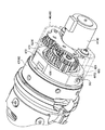
図4ないし図7は、モータ41及び減速機構42を示す図である。具体的に、図4及び図5は、アクチュエータ4が支持部23に組み込まれた状態を示す斜視図である。図6及び図7は、モータ41及び減速機構42の分解斜視図である。
モータ41は、制御部24にて制御される例えばステッピングモータで構成され、第2関節部232B(可動部)または第3関節部232C(可動部)に動力を与える動力源である。
As shown in FIG. 3, the
4 to 7 are views showing the
The
減速機構42は、モータ41の出力軸に設けられ、当該出力軸の回転を所定の減速比で減速する。この減速機構42は、図4ないし図7に示すように、モータ41の出力軸側から順に第1〜第6歯車421〜426を備える。本実施の形態では、第1〜第6歯車421〜426は、平歯車で構成されている。すなわち、減速機構42は、モータ41から第2関節部232Bまたは第3関節部232Cへの動力伝達経路に設けられ、本発明に係る歯車機構としての機能を有する。
本実施の形態では、第1〜第6歯車421〜426における互いに噛合する5組の歯車は、モータ41の出力軸側から順に、減速比が大きくなるように設定されている。すなわち、互いに噛合する第1,第2歯車421,422の減速比が最も小さく、互いに噛合する第5,第6歯車425,426の減速比が最も大きく設定されている。
そして、モータ41と減速機構42における第1〜第5歯車421〜425とは、図4ないし図7に示すように、第1支持部材46に支持されている。一方、第6歯車426は、図4または図5に示すように、第1支持部材46とは別体で構成された第2支持部材47に対して、当該第2支持部材47の端部471から外部に露出した状態で軸支されている。
The
In the present embodiment, the five sets of gears meshing with each other in the first to
The first to
第1支持部材46は、有底円筒形状を有する。そして、モータ41は、第1支持部材46における底部分の外面に取り付けられる。なお、第1歯車421は、モータ41の出力軸に取り付けられる。また、第2〜第5歯車422〜425は、第1支持部材46における底部分の外面及び内面にそれぞれ設けられた第1〜第4軸支部461〜464(図6,図7)にて回転可能に軸支される。
そして、第1支持部材46の内部に第2支持部材47の端部471を挿入するように第1,第2支持部材46,47を互いに嵌合(接続)する(第1支持部材46における側壁部465(図4〜図7)の内面を第2支持部材47における端部471側の外周面472(図4,図5)に当接する)ことで、第1支持部材46に軸支された第5歯車425と、第2支持部材47に軸支された第6歯車426とが互いに噛合する。
The
Then, the first and
ここで、第1,第2支持部材46,47は、第5,第6歯車425,426のバックラッシ量を低減するバックラッシ低減機構48(図4〜図7)として機能する。
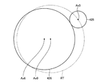
図8及び図9は、バックラッシ低減機構48を用いたバックラッシ量を調整する方法を説明する図である。なお、図8では、第5,第6歯車425,426を仮想的に円で示している。また、図9では、バックラッシ量の調整前の状態を実線で示し、バックラッシ量の調整後の状態を二点鎖線で示している。
バックラッシ低減機構48は、「互いに噛合する歯車の中心間の距離を変更すると、当該歯車のバックラッシ量が調整される」点に着目した機構である。
具体的に、第1,第2支持部材46,47において、互いに当接する面(第1支持部材46における側壁部465の内面と、第2支持部材47における外周面472)は、第5歯車425の回転軸Ax5(図8)と第6歯車426の回転軸Ax6(図8)とは独立し、当該各回転軸Ax5,Ax6にそれぞれ平行となる軸Ax0(図8)を中心とする回転軌跡を描くように形成されている。そして、第1支持部材46は、側壁部465の内面が第2支持部材47における外周面472上を摺動することで、軸Ax0(以下、回転軸Ax0と記載)を中心として、第2支持部材47に対して回転可能に構成されている。
このように回転軸Ax0を中心として第1支持部材46を回転させた場合には、上述したように回転軸Ax0が回転軸Ax6に対して偏心しているため、図8に示すように、第5歯車425の中心が回転軌跡RTを描くように移動する。すなわち、図8または図9に示すように、第5,第6歯車425,426の中心間の距離が変更され(図9では、中心間の距離の変化量をDCとして図示)、第5,第6歯車425,426のバックラッシ量が調整される。
Here, the first and
8 and 9 are diagrams illustrating a method of adjusting the backlash amount using the
The
Specifically, the surfaces of the first and
When the
ここで、第1支持部材46における側壁部465には、表裏を貫通するとともに、回転軸Ax0を中心とする回転軌跡RTに沿って延びる複数(本実施の形態では、3つ)の長穴4651(図5〜図7)が形成されている。一方、第2支持部材47における外周面472には、長穴4651に対応した位置に固定用孔4721(図5)がそれぞれ形成されている。
そして、第5,第6歯車425,426のバックラッシ量の調整は、以下に示すように実行される。
先ず、作業者は、所望のバックラッシ量と同一の厚み寸法を有するテープを第5歯車425の歯面に貼り付ける。
次に、作業者は、第1,第2支持部材46,47を互いに嵌合させる。そして、作業者は、3つの長穴4651を介して、3つの固定ネジSc(図4,図6,図7)を緩めた状態(回転軸Ax0を中心として第1支持部材46を回転可能な状態)で3つの固定用孔4721にそれぞれ螺合する。
次に、作業者は、上述したテープを介して第5,第6歯車425,426の各歯面同士が互いに当接するまで、第2支持部材47に対し、回転軸Ax0を中心として第1支持部材46を回転させる。
次に、作業者は、3つの固定ネジScを3つの固定用孔4721に締結し、第2支持部材47に対して第1支持部材46を固定する。
最後に、作業者は、側壁部465に形成された切欠部4652(図4〜図7)を介して、第5歯車425の歯面に貼り付けたテープを剥がす。
Here, in the
The adjustment of the backlash amount of the fifth and
First, the operator attaches a tape having the same thickness dimension as the desired backlash amount to the tooth surface of the
Next, the operator fits the first and
Next, the operator makes the first support about the rotation axis Ax0 to the
Next, the operator fastens the three fixing screws Sc to the three fixing
Finally, the operator peels off the tape attached to the tooth surface of the
ドライブシャフト43は、一端側がクラッチ44を介して減速機構42に接続し、他端側が第2関節部232B(可動部)または第3関節部232C(可動部)に接続する。そして、ドライブシャフト43は、クラッチ44を介してモータ41の回転が伝達され、当該モータ41の回転を第2関節部232B(可動部)または第3関節部232C(可動部)に伝達することで、第2軸O2または第3軸O3まわりに可動部を回転させる。
クラッチ44は、制御部24にて制御される電磁クラッチ(例えば、励磁作動型クラッチ)で構成され、アーマチュア441(図3)をドライブシャフト43の軸方向に移動することにより、減速機構42とドライブシャフト43とを接続してモータ41からドライブシャフト43への動力の伝達を許容した許容状態、または、減速機構42とドライブシャフト43との接続を解除して当該伝達を遮断した遮断状態に切り替える。
すなわち、クラッチ44は、本発明に係る状態切替部としての機能を有する。
ブレーキ45は、制御部24による制御の下、アーマチュア451(図3)をドライブシャフト43の軸方向に移動することにより、電気的にドライブシャフト43の解放及び拘束を切り替える電磁ブレーキ(例えば、無励磁作動型ブレーキ)で構成される。
The
The clutch 44 is configured by an electromagnetic clutch (for example, an excitation-actuated clutch) controlled by the
That is, the clutch 44 has a function as a state switching unit according to the present invention.
The
〔制御部による第1,第2制御〕
制御部24は、XY移動動作モードにおいて、以下に示す第1,第2制御を実行する。
第1制御は、術者によるフットスイッチ25への操作(+X軸方向、−X軸方向、+Y軸方向、または、−Y軸方向への撮像視野の移動指示)に応じて、モータ41を動作させる制御である。
具体的に、フットスイッチ25への操作が+X軸方向への撮像視野の移動指示であった場合には、制御部24は、第2関節部232B(可動部)の動力源となるモータ41を第1方向に回転(以下、順回転と記載)させる。一方、フットスイッチ25への操作が−X軸方向への撮像視野の移動指示であった場合には、制御部24は、第2関節部232Bの動力源となるモータ41を第1方向とは逆方向の第2方向に回転(以下、逆回転と記載)させる。また、フットスイッチ25への操作が+Y軸方向への撮像視野の移動指示であった場合には、制御部24は、第3関節部232C(可動部)の動力源となるモータ41を順回転させる。一方、フットスイッチ25への操作が−Y軸方向への撮像視野の移動指示であった場合には、制御部24は、第3関節部232C(可動部)の動力源となるモータ41を逆回転させる。
[First and second control by control unit]
The
The first control is to operate the
Specifically, when the operation on the
また、第2制御は、第1制御を完了してモータ41の動作を停止させた後に、第1制御時でのモータ41の回転方向とは逆方向に当該モータ41を回転させ、第5,第6歯車425,426において、当該逆方向への当該モータ41の回転に応じて互いに噛合する側の各歯面間の距離と、噛合しない側の各歯面間の距離とを第5,第6歯車425,426のバックラッシ量(バックラッシ低減機構48にて調整された後のバックラッシ量)の半分の値にする制御である。
なお、上述した逆方向へのモータ41の回転に応じて互いに噛合する側の各歯面は、図9に示すように、各歯面4251,4261、及び各歯面4252,4262の一方の各歯面に相当する。そして、当該一方の各歯面が本発明に係る第1歯面に相当し、当該一方の各歯面間の距離が本発明に係る第1距離に相当する。また、上述した逆方向へのモータ41の回転に応じて互いに噛合しない側の各歯面は、各歯面4251,4261、及び、各歯面4252,4262の他方の各歯面に相当する。そして、当該他方の各歯面が本発明に係る第2歯面に相当し、当該他方の各歯面間の距離が本発明に係る第2距離に相当する。すなわち、第2制御では、各歯面4251,4261間の距離と各歯面4252,4262間の距離とを第5,第6歯車425,426のバックラッシ量の半分の値にする(第1,第2距離をバックラッシ量の半分の値にする)。
In the second control, after the first control is completed and the operation of the
As shown in FIG. 9, the tooth surfaces on the side meshing with each other in response to the rotation of the
以下、第1,第2制御の詳細なフローについて説明する。
図10は、制御部24による第1,第2制御を示すフローチャートである。
第1制御は、図10に示すステップS1〜S7に相当する。また、第2制御は、図10に示すステップS8〜S11に相当する。
以下では、説明の便宜上、第2制御によるモータ41の回転に応じて互いに噛合する側の各歯面を各歯面4251,4261(以下、各第1歯面4251,4261と記載)とし、当該各第1歯面4251,4261間の距離を第1距離と記載する。また、第2制御によるモータ41の回転に応じて互いに噛合しない側の各歯面を各歯面4252,4262(以下、各第2歯面4252,4262と記載)とし、当該各第2歯面4252,4262間の距離を第2距離と記載する。なお、第2制御の直前に実行される第1制御と当該第2制御とでは上述したようにモータ41の回転方向が逆方向であるため、当該第1制御によるモータ41の回転に応じて互いに噛合する側の各歯面は各第2歯面4252,4262となり、噛合しない側の各歯面は各第1歯面4251,4261となる。
また、以下では、既に第2制御(ステップS8〜S11)が実行され、第1,第2距離が同一の値(第5,第6歯車425,426のバックラッシ量の半分の値)に設定されているものとして説明を開始する。説明の便宜上、当該バックラッシ量を「1.0mm」とする。また、既に第2制御(ステップS8〜S11)が実行され、遮断状態に切り替えられている(クラッチOFF)とともに、ブレーキ45が作動している(ドライブシャフト43が拘束されている)状態から説明を開始する。
Hereinafter, a detailed flow of the first and second controls will be described.
FIG. 10 is a flowchart showing the first and second controls by the
The first control corresponds to steps S1 to S7 shown in FIG. The second control corresponds to steps S8 to S11 shown in FIG.
Hereinafter, for convenience of description, the respective tooth surfaces on the side that mesh with each other in accordance with the rotation of the
In the following, the second control (steps S8 to S11) has already been executed, and the first and second distances are set to the same value (half the backlash amount of the fifth and
先ず、制御部24は、術者によるフットスイッチ25への操作(+X軸方向、−X軸方向、+Y軸方向、または、−Y軸方向への撮像視野の移動指示)があったか否か(フットスイッチ25がONしたか否か)を常時、監視する(ステップS1)。
フットスイッチ25がONしたと判断した場合(ステップS1:Yes)には、制御部24は、ステップS1での移動指示に応じたモータ41を第1回転速度で当該移動指示に応じた回転方向に回転させる(ステップS2)。例えば、制御部24は、ステップS2において、モータ41に対して1秒間に2000パルスのパルス信号を0.25秒間、出力し、当該モータ41を第1回転速度で回転させる。
これにより、第1,第2距離が第5,第6歯車425,426のバックラッシ量の半分の値「0.5mm」であったところ、第2歯面4252,4262同士が互いに当接し、第2距離が「0」となり、第1距離がバックラッシ量と同一の値「1.0mm」となる。
First, the
If it is determined that the
As a result, when the first and second distances are half the value of the backlash of the fifth and
次に、制御部24は、クラッチ44の動作を制御して遮断状態(クラッチOFF)から許容状態(クラッチON)に切り替え(ステップS3)、ブレーキ45の動作を制御してブレーキ45を解除(ドライブシャフト43を開放)する(ステップS4)。
Next, the
次に、制御部24は、ステップS1での移動指示に応じたモータ41を第1回転速度よりも低い第2回転速度で当該移動指示に応じた回転方向(ステップS2での回転方向と同一方向)に回転させる(ステップS5)。例えば、制御部24は、ステップS5において、モータ41に対して1秒間に200パルスのパルス信号を出力し、当該モータ41を第2回転速度(第1回転速度の1/10)で回転させる。
そして、制御部24は、ステップS1での術者によるフットスイッチ25への操作が解除されたか否か(フットスイッチ25がOFFしたか否か)を常時、監視し(ステップS6)、当該操作が継続している間、ステップS5の処理を継続する。一方、フットスイッチ25がOFFしたと判断した場合(ステップS6:Yes)には、制御部24は、ステップS5の処理を完了(第2回転速度でのモータ41の回転を停止)する(ステップS7)。
すなわち、ステップS3〜S7の処理により、術者によりフットスイッチ25がONしている間、モータ41の回転が第2関節部232B(可動部)または第3関節部232C(可動部)に伝達され、顕微鏡部21による撮像視野が+X軸方向、−X軸方向、+Y軸方向、または−Y軸方向に移動することとなる。
Next, the
Then, the
That is, by the processing of steps S3 to S7, the rotation of the
以上の第1制御(ステップS1〜S7)の後、制御部24は、第2制御を実行する(ステップS8〜S11)。
先ず、制御部24は、クラッチ44の動作を制御して許容状態(クラッチON)から遮断状態(クラッチOFF)に切り替え(ステップS8)、ブレーキ45の動作を制御してブレーキ45を作動(ドライブシャフト43を拘束)する(ステップS9)。
After the above first control (steps S1 to S7), the
First, the
次に、制御部24は、第1制御(ステップS1〜S7)で動作させたモータ41を当該第1制御時でのモータ41の回転方向とは逆方向に第1回転速度で回転させる(ステップS10)。例えば、制御部24は、ステップS10において、モータ41に対して1秒間に2000パルスのパルス信号を0.25秒間、出力し、当該モータ41を第1回転速度で逆方向に回転させた後、当該モータ41を停止させる(ステップS11)。この後、制御部24は、ステップS1に戻る。
これにより、第1制御によって第2距離が「0」であり、第1距離が第5,第6歯車425,426のバックラッシ量と同一の値「1.0mm」であったところ、第1,第2距離がバックラッシ量の半分の値「0.5mm」となる。
Next, the
Thereby, when the second distance is “0” by the first control and the first distance is the same value “1.0 mm” as the backlash amount of the fifth and
以上説明した本実施の形態に係る医療用観察装置2では、フットスイッチ25へのユーザ操作に応じてモータ41を動作させる第1制御を実行するとともに、当該第1制御を完了して当該モータ41の動作を停止させた後、第1,第2距離を第5,第6歯車425,426のバックラッシ量の半分の値にする第2制御を実行する。すなわち、第1制御によって、第1距離が第5,第6歯車425,426のバックラッシ量と同一の値となり、第2距離が0となっていたところ、当該第1制御の後に第2制御を実行することで、第1,第2距離を第5,第6歯車425,426のバックラッシ量の半分の値にする。
このため、第1,第2制御を実行した後に、フットスイッチ25にユーザ操作がなされ、当該第1制御時での回転方向とは逆方向(当該第2制御時での回転方向と同一方向)にモータ41を回転させる第1制御を実行する場合には、第5,第6歯車425,426のバックラッシ量の半分の値である第1距離だけ詰めれば、第5,第6歯車425,426を互いに噛合させ、モータ41の回転を第2関節部232B(可動部)または第3関節部232C(可動部)に伝達する(顕微鏡部21の位置及び姿勢を変更する(顕微鏡部21による撮像視野を移動する))ことができる。
したがって、本実施の形態に係る医療用観察装置2によれば、直前に実行した第1制御時での回転方向とは逆方向にモータ41を回転させる第1制御を実行する場合において、第5,第6歯車425,426の空走期間を短縮し、撮像視野を迅速に移動することができる、という効果を奏する。
In the medical observation device 2 according to the present embodiment described above, the first control for operating the
Therefore, after executing the first and second controls, a user operation is performed on the
Therefore, according to the medical observation apparatus 2 according to the present embodiment, when performing the first control for rotating the
特に、第2制御を実行することで、第1,第2距離を第5,第6歯車425,426のバックラッシ量の半分の値にしている。このため、第1,第2制御を実行した後に、フットスイッチ25にユーザ操作がなされ、当該第1制御時での回転方向と同一方向(当該第2制御時での回転方向とは逆方向)にモータ41を回転させる第1制御を実行する場合であっても、第5,第6歯車425,426のバックラッシ量の半分の値である第2距離だけ詰めれば、第5,第6歯車425,426を互いに噛合させ、モータ41の回転を第2関節部232Bまたは第3関節部232C(可動部)に伝達することができる。
このため、直前に実行した第1制御時での回転方向とは逆方向にモータ41を回転させる第1制御を実行する場合と、直前に実行した第1制御時での回転方向と同一方向にモータ41を回転させる第1制御を実行する場合とで、第5,第6歯車425,426の空走期間を同一にすることができる。したがって、当該各場合での操作に対して、術者は違和感を覚えることがない。
In particular, by executing the second control, the first and second distances are set to half the backlash amount of the fifth and
For this reason, the first control for rotating the
また、本実施の形態に係る医療用観察装置2では、第2制御の後に第1制御を実行する際、第1距離または第2距離が0(上述したステップS2では第2距離が0)になるまで第1回転速度でモータ41を回転させ、当該0になった後に当該第1回転速度よりも低い第2回転速度で当該モータを回転させる。
このため、第2制御の後に第1制御を実行する際、比較的に速い第1回転速度でモータ41を回転させるので、第5,第6歯車425,426の空走期間をさらに短縮し、撮像視野をさらに迅速に移動することができる。
Further, in the medical observation apparatus 2 according to the present embodiment, when the first control is executed after the second control, the first distance or the second distance becomes 0 (the second distance is 0 in step S2 described above). The
Therefore, when the first control is executed after the second control, the
ところで、第1制御を実行する際、許容状態(クラッチON)において、比較的に速い第1回転速度でモータ41を回転させた場合には、モータ41に過大な負荷が掛かり、脱調する恐れがある。
本実施の形態に係る医療用観察装置2では、第1制御を実行する際、遮断状態(クラッチOFF、モータ41に過大な負荷が掛からない状態)において、比較的に速い第1回転速度でモータ41を回転させている。このため、脱調する恐れがない。
By the way, when the first control is executed, if the
In the medical observation device 2 according to the present embodiment, when the first control is executed, the motor is driven at a relatively high first rotation speed in the disconnected state (the clutch is off and no excessive load is applied to the motor 41). 41 is rotating. For this reason, there is no risk of step-out.
また、本実施の形態に係る医療用観察装置2では、第5歯車425を軸支する第1支持部材46と、第6歯車426を軸支する第2支持部材47とで構成され、第5,第6歯車425,426のバックラッシ量を低減するバックラッシ低減機構48を採用している。
このため、簡単な構造で第5,第6歯車425,426のバックラッシ量を低減することができる。また、当該バックラッシ量を低減することで、第5,第6歯車425,426の空走期間をさらに短縮し、撮像視野をさらに迅速に移動することができる。
特に、機械的にバックラッシ量を低減するバックラッシ低減機構48と、第2制御により第1,第2距離をバックラッシ量の半分の値とする構成とを併用することにより、第5,第6歯車425,426の空走期間を効率的に短縮することができる。
また、バックラッシ低減機構48は、第1〜第6歯車421〜426における互いに噛合する5組の歯車のうち、減速比が最も大きい組である第5,第6歯車425,426のバックラッシ量を低減する。すなわち、減速比の小さい他の組の各歯車のバックラッシ量を低減する構成と比較して、減速比を考慮して最も高い効果を得ることができる。
In the medical observation device 2 according to the present embodiment, the
Therefore, the backlash amount of the fifth and
In particular, by using the
Further, the
(その他の実施の形態)
ここまで、本発明を実施するための形態を説明してきたが、本発明は上述した実施の形態によってのみ限定されるべきものではない。
上述した実施の形態に係る第2制御(ステップS8〜S11)では、第1,第2距離をバックラッシ量の半分の値としていたが、第1,第2距離がバックラッシ量よりも小さい値となるように制御していればよく、第1,第2距離をバックラッシ量の半分の値以外のその他の値とするように制御しても構わない。
(Other embodiments)
The embodiments for carrying out the present invention have been described so far, but the present invention should not be limited only to the above embodiments.
In the second control (steps S8 to S11) according to the above-described embodiment, the first and second distances are set to half the value of the backlash amount, but the first and second distances are set to values smaller than the backlash amount. The control may be performed so that the first and second distances are set to other values than half the backlash amount.
上述した実施の形態に係る第1制御(ステップS1〜S7)では、ステップS2(モータ41を第1回転速度で回転)をクラッチOFFの状態で実行していたが、これに限られず、クラッチONの状態で実行しても構わない。また、ステップS2をブレーキ45が作動した状態で実行していたが、これに限られず、ブレーキ45を解除した状態で実行しても構わない。すなわち、ステップS3,S4をステップS2の前に実行しても構わない。
また、上述した実施の形態に係る第2制御(ステップS8〜S11)では、ステップS10において、第1回転速度でモータ41を回転させていたが、これに限られず、第2回転速度でモータ41を回転させても構わない。
In the first control (steps S <b> 1 to S <b> 7) according to the above-described embodiment, step S <b> 2 (rotating the
In the second control (steps S8 to S11) according to the above-described embodiment, the
上述した実施の形態では、本発明に係る歯車機構として、減速機構42を採用していたが、これに限られない。例えば、ドライブシャフト43の他端と第2,第3関節部232B,232C(可動部)との間を接続し、複数の歯車を有する動力伝達機構(図示略)を本発明に係る歯車機構として構成しても構わない。
In the above-described embodiment, the
上述した実施の形態では、バックラッシ低減機構48として、第2支持部材47に対し、回転軸Ax0を中心として第1支持部材46を回転可能な機構を採用していたが、これに限られず、互いに噛合する第5,第6歯車425,426の中心間の距離を変更可能とする機構であれば、その他の機構を採用しても構わない。
In the above-described embodiment, as the
図11は、本発明の実施の形態の変形例を示す図である。
上述した実施の形態において、XY移動動作モードでの制御部24の動作として、図11に示すように動作しても構わない。
以下では、各歯面4251,4261間の距離、及び各歯面4252,4262間の距離の一方の距離が「0」となっており、他方の距離が第5,第6歯車425,426のバックラッシ量と同一の値になっているものとして説明を開始する。説明の便宜上、上述した実施の形態と同様に、当該バックラッシ量を「1.0mm」とする。また、上述した実施の形態と同様に、遮断状態に切り替えられている(クラッチOFF)とともに、ブレーキ45が作動している(ドライブシャフト43が拘束されている)状態から説明を開始する。
なお、本変形例に係るフローは、図11に示すように、上述した実施の形態で説明したフロー(図10)に対して、ステップS10,S11が省略され、ステップS2の代わりにステップS2Aが採用され、さらに、ステップS12〜S16が追加されている点が異なる。
このため、以下では、ステップS2A,S12〜S16のみを説明する。
FIG. 11 is a diagram showing a modification of the embodiment of the present invention.
In the above-described embodiment, the operation of the
In the following, one of the distance between the tooth surfaces 4251 and 4261 and the distance between the tooth surfaces 4252 and 4262 is “0”, and the other distance is the distance between the fifth and
Note that, as shown in FIG. 11, the flow according to the present modification differs from the flow (FIG. 10) described in the above-described embodiment in that steps S10 and S11 are omitted, and step S2A is performed instead of step S2. The difference is that steps S12 to S16 are added.
Therefore, only steps S2A and S12 to S16 will be described below.
ステップS12は、フットスイッチ25がONしたと判断した場合(ステップS1:Yes)に実行される。
具体的に、制御部24は、ステップS12において、ステップS1での移動指示が直前に動作させた回転方向とは逆方向にモータ41を回転させる移動指示であるか否かを判断する。
例えば、直前にモータ41を「順回転」させており、ステップS1での移動指示が当該モータ41を「逆回転」させる移動指示であった場合には、制御部24は、ステップS12において、「Yes」と判断する。一方、直前にモータ41を「順回転」させており、ステップ1での移動指示が当該モータ41を「順回転」させる移動指示であった場合には、制御部24は、ステップS12において、「No」と判断する。
Step S12 is executed when it is determined that the
Specifically, in step S12, the
For example, if the
ステップS2Aは、ステップS12で「Yes」と判断された場合に実行される。
具体的に、制御部24は、ステップS2Aにおいて、ステップS1での移動指示に応じたモータ41を第1回転速度で当該移動指示に応じた回転方向に回転させる。例えば、制御部24は、モータ41に対して1秒間に2000パルスのパルス信号を0.5秒間、出力し、当該モータ41を第1回転速度で回転させる。
これにより、各歯面4251,4261間の距離、及び各歯面4252,4262間の距離の一方の距離が「0」であり、他方の距離が第5,第6歯車425,426のバックラッシ量と同一の値「1.0mm」であったところ、各歯面4251,4261、及び各歯面4252,4262のうち、互いに離間していた歯面同士が互いに当接し、当該他方の距離が「0」となり、当該一方の距離がバックラッシ量と同一の値「1.0mm」となる。
ステップS2Aの後、制御部24は、上述した実施の形態で説明したステップS3〜S9を実行し、ステップS1に戻る。
Step S2A is executed when “Yes” is determined in step S12.
Specifically, in step S2A, the
As a result, one of the distance between the tooth surfaces 4251 and 4261 and the distance between the tooth surfaces 4252 and 4262 is “0”, and the other distance is the backlash amount of the fifth and
After step S2A, the
ステップS13〜S16は、ステップS12で「No」と判断された場合に実行される。なお、ステップS13〜S16は、ステップS3〜S6と同様の処理である。
そして、フットスイッチ25がOFFしたと判断した場合(ステップS16:Yes)には、制御部24は、ステップS7に移行する。
すなわち、ステップS13〜S16では、直前に動作させた回転方向と同一の方向にモータ41を回転させているため、各歯面4251,4261間の距離、及び各歯面4252,4262間の距離の一方の距離は「0」の状態が維持され、他方の距離は第5,第6歯車425,426のバックラッシ量と同一の値「1.0mm」の状態が維持される。
Steps S13 to S16 are executed when "No" is determined in step S12. Steps S13 to S16 are the same processing as steps S3 to S6.
If it is determined that the
That is, in steps S13 to S16, since the
上述した実施の形態では、制御部24は、XY移動動作モードにおいて、術者によるフットスイッチ25へのユーザ操作に応じて、顕微鏡部21による撮像視野を+X軸方向、−X軸方向、+Y軸方向、または−Y軸方向に移動させていたが、これに限られない。例えば、外部機器からの移動指示(例えば、撮像視野の移動方向及びその移動量の指示)に応じて、顕微鏡部21による撮像視野を移動させる構成を採用しても構わない。
このような構成であっても、上述したバックラッシに起因した問題が生じる。例えば、直前の移動指示が−X軸方向への移動指示であり、当該移動指示の後、+X軸方向に5mm、撮像視野を移動させる移動指示があった場合には、直前に動作させた回転方向とは逆方向にモータ41を回転させることとなるため、バックラッシにより第5,第6歯車425,426の空走期間が存在し、指示通りに撮像視野を移動させることができない(5mmではなく、例えば、4mmしか+X軸方向に移動しない)。
この際、制御部24は、直前の移動指示と現在の移動指示とを比較して直前に動作させた回転方向とは逆方向にモータ41を回転させることを把握した場合には、現在の移動指示に含まれる移動量をバックラッシ量分、加算した移動量に補正(例えば、5mmの移動量である場合にはバックラッシ量を加算した6mmに補正)し、当該補正した移動量だけ撮像視野を移動するように構成する。このように構成すれば、指示通りに撮像視野を移動させることができる。
In the above-described embodiment, in the XY movement operation mode, the
Even with such a configuration, the problem caused by the backlash described above occurs. For example, when the immediately preceding movement instruction is a movement instruction in the −X axis direction, and after the movement instruction, there is a movement instruction to move the imaging visual field by 5 mm in the + X axis direction, the rotation performed immediately before Since the
At this time, the
1 医療用観察システム
2 医療用観察装置
3 表示装置
4 アクチュエータ
21 顕微鏡部
22 ベース部
23 支持部
24 制御部
25 フットスイッチ
41 モータ
42 減速機構
43 ドライブシャフト
44 クラッチ
45 ブレーキ
46,47 第1,第2支持部材
48 バックラッシ低減機構
221 キャスター
231A〜231E 第1〜第5アーム部
232A〜232F 第1〜第6関節部
421〜426 第1〜第6歯車
441,451 アーマチュア
461〜464 第1〜第4軸支部
465 側壁部
471 端部
472 外周面
4651 長穴
4652 切欠部
4721 固定用孔
Ax0,Ax5,Ax6 回転軸
DC 中心間の距離の変化量
O1〜O6 第1〜第6軸
OP 術者
PA 患者
RT 回転軌跡
Sc 固定ネジ
Reference Signs List 1 medical observation system 2
Claims (7)
複数のアーム部、及び当該複数のアーム部を互いに回動可能に接続する複数の関節部を有し、先端で前記撮像部を支持する支持部と、
前記支持部に設けられ、前記複数の関節部の少なくとも一つの関節部に動力を与え、当該関節部にて接続された2つの前記アーム部を相対的に回動させるモータと、
互いに噛合する2つの歯車を有し、前記モータから前記少なくとも一つの関節部への動力伝達経路に設けられる歯車機構と、
ユーザ操作を受け付ける操作受付部と、
前記操作受付部が受け付けた前記ユーザ操作に応じて前記モータを動作させる第1制御を実行するとともに、当該第1制御を完了して当該モータの動作を停止させた後、第2制御を実行する制御部とを備え、
前記動力伝達経路には、
前記歯車機構と前記少なくとも一つの関節部との間に、当該歯車機構から当該少なくとも一つの関節部への動力の伝達を遮断した遮断状態、または当該伝達を許容した許容状態に切り替える状態切替部が設けられ、
前記支持部は、
前記撮像部の位置及び姿勢を固定する固定モードと、ユーザによる当該支持部への手動操作に応じて前記撮像部の位置及び姿勢を調整可能とするオールフリーモードと、前記操作受付部が受け付けた前記ユーザ操作に応じて前記撮像部による撮像視野を移動させる移動動作モードとのいずれかの動作モードで動作し、
前記制御部は、
前記移動動作モードにおいて、前記第1制御及び前記第2制御を実行し、前記第2制御を実行することで、前記第1制御時での前記モータの回転方向とは逆方向に当該モータを回転させ、前記2つの歯車において、当該逆方向への当該モータの回転に応じて互いに噛合する側の各第1歯面間の第1距離と、噛合しない側の各第2歯面間の第2距離とを当該2つの歯車のバックラッシ量よりもそれぞれ小さくするとともに、
前記オールフリーモードにおいて、前記状態切替部を前記遮断状態に設定する
ことを特徴とする医療用観察装置。 An image pickup unit capable of enlarging an image of an observation target and taking an image;
A plurality of arm portions, and a plurality of joint portions that rotatably connect the plurality of arm portions to each other, and a support portion that supports the imaging unit at a distal end,
A motor that is provided on the support portion, that supplies power to at least one joint portion of the plurality of joint portions, and that relatively rotates the two arm portions connected by the joint portion;
A gear mechanism having two gears meshing with each other, and provided in a power transmission path from the motor to the at least one joint;
An operation receiving unit that receives a user operation;
Executing first control for operating the motor in response to the user operation received by the operation receiving unit, and executing second control after completing the first control and stopping the operation of the motor; And a control unit,
In the power transmission path,
Between the gear mechanism and the at least one joint, a state switching unit that switches between a cutoff state in which power transmission from the gear mechanism to the at least one joint is cut off, or an allowable state in which the transmission is allowed, Provided,
The support section is
A fixed mode for fixing the position and orientation of the imaging unit, an all-free mode for adjusting the position and orientation of the imaging unit in response to a manual operation on the support unit by a user, and the operation reception unit received Operate in one of the operation modes of a movement operation mode for moving an imaging field of view by the imaging unit according to the user operation,
The control unit includes:
In the moving operation mode, the first control and the second control are executed, and by executing the second control, the motor is rotated in a direction opposite to the rotation direction of the motor during the first control. In the two gears, a first distance between the first tooth surfaces on the side that meshes with each other in response to the rotation of the motor in the opposite direction, and a second distance between the second tooth surfaces on the side that does not mesh with each other. While making the distances smaller than the backlash amount of the two gears ,
In the all-free mode, the state switching unit is set to the cutoff state .
前記第2制御を実行することで、前記第1距離と前記第2距離とを前記バックラッシ量の半分の値にする
ことを特徴とする請求項1に記載の医療用観察装置。 The control unit includes:
The medical observation device according to claim 1, wherein the first control and the second control are performed to set the first distance and the second distance to a half value of the backlash amount by executing the second control.
前記第2制御の後に前記第1制御を実行する際、前記第2距離が0になるまで第1回転速度で前記モータを回転させ、当該0になった後に当該第1回転速度よりも低い第2回転速度で当該モータを回転させる
ことを特徴とする請求項1または2に記載の医療用観察装置。 The control unit includes:
When performing the first control after the second control, prior Symbol rotates the motor at a first rotational speed to a second distance becomes 0, the lower than the first rotational speed after reaching to the 0 The medical observation device according to claim 1, wherein the motor is rotated at a second rotation speed.
前記遮断状態において、前記第1回転速度で前記モータを回転させ、
前記許容状態において、前記第2回転速度で前記モータを回転させる
ことを特徴とする請求項3に記載の医療用観察装置。 Before Symbol control unit,
In the shut-off state, the motor is rotated at the first rotation speed,
The medical observation device according to claim 3, wherein the motor is rotated at the second rotation speed in the allowable state.
前記第1支持部材とは別体で構成され、前記2つの歯車の他方の歯車を回転可能に軸支する第2支持部材とを備え、
前記第1支持部材及び前記第2支持部材は、
互いに接続することで、前記2つの歯車を互いに噛合させ、
前記第1支持部材は、
前記第2支持部材に対して移動可能とし、当該第2支持部材に対して移動することで前記2つの歯車のバックラッシ量を変更可能とする
ことを特徴とする請求項1〜4のいずれか一つに記載の医療用観察装置。 A first support member rotatably supporting one of the two gears;
A second support member that is configured separately from the first support member and rotatably supports the other of the two gears;
The first support member and the second support member,
By connecting with each other, the two gears mesh with each other,
The first support member includes:
The backlash amount of the two gears can be changed by being movable with respect to the second support member and moving with respect to the second support member. 4. The medical observation device according to any one of the above.
平歯車でそれぞれ構成され、
前記第1支持部材は、
前記第2支持部材に対して回転可能とし、当該第2支持部材に対して回転することで前記2つの歯車のバックラッシ量を変更可能とし、
前記第1支持部材の回転軸は、
前記2つの歯車の各回転軸とは独立し、当該各回転軸にそれぞれ平行となる軸である
ことを特徴とする請求項5に記載の医療用観察装置。 The two gears are
Each composed of spur gears,
The first support member includes:
The second support member is rotatable, and the second support member is rotated to change a backlash amount of the two gears;
The rotation axis of the first support member is
The medical observation device according to claim 5, wherein each of the rotation axes of the two gears is independent of and parallel to each of the rotation axes.
前記2つの歯車を含む3つ以上の歯車を有し、前記モータの回転を減速する減速機構であり、
前記2つの歯車は、
前記減速機構における互いに噛合する複数組の歯車のうち、減速比が最も大きい組の歯車である
ことを特徴とする請求項5または6に記載の医療用観察装置。 The gear mechanism,
A reduction mechanism that has three or more gears including the two gears and reduces the rotation of the motor,
The two gears are
The medical observation device according to claim 5, wherein, among the plurality of sets of gears meshing with each other in the speed reduction mechanism, the set of gears has the largest reduction ratio.
Priority Applications (2)
| Application Number | Priority Date | Filing Date | Title |
|---|---|---|---|
| JP2016048906A JP6654066B2 (en) | 2016-03-11 | 2016-03-11 | Medical observation device |
| US15/434,434 US10646302B2 (en) | 2016-03-11 | 2017-02-16 | Medical observation device |
Applications Claiming Priority (1)
| Application Number | Priority Date | Filing Date | Title |
|---|---|---|---|
| JP2016048906A JP6654066B2 (en) | 2016-03-11 | 2016-03-11 | Medical observation device |
Publications (3)
| Publication Number | Publication Date |
|---|---|
| JP2017158970A JP2017158970A (en) | 2017-09-14 |
| JP2017158970A5 JP2017158970A5 (en) | 2019-03-22 |
| JP6654066B2 true JP6654066B2 (en) | 2020-02-26 |
Family
ID=59788709
Family Applications (1)
| Application Number | Title | Priority Date | Filing Date |
|---|---|---|---|
| JP2016048906A Active JP6654066B2 (en) | 2016-03-11 | 2016-03-11 | Medical observation device |
Country Status (2)
| Country | Link |
|---|---|
| US (1) | US10646302B2 (en) |
| JP (1) | JP6654066B2 (en) |
Families Citing this family (8)
| Publication number | Priority date | Publication date | Assignee | Title |
|---|---|---|---|---|
| JP2016158751A (en) * | 2015-02-27 | 2016-09-05 | ソニー株式会社 | Actuator and medical support arm device |
| US20200306003A1 (en) | 2017-12-06 | 2020-10-01 | Sony Olympus Medical Solutions Inc. | Medical control apparatus and medical observation system |
| CN109955254B (en) * | 2019-04-30 | 2020-10-09 | 齐鲁工业大学 | Mobile robot control system and teleoperation control method for robot end pose |
| CN111759485B (en) * | 2020-06-18 | 2022-07-29 | 昌乐县妇幼保健院 | Horizontal ophthalmic optical observation support |
| CN113844845B (en) * | 2020-06-28 | 2023-05-02 | 菜鸟智能物流控股有限公司 | Butt joint device, method and transportation equipment |
| US11712804B2 (en) | 2021-03-29 | 2023-08-01 | Samsung Electronics Co., Ltd. | Systems and methods for adaptive robotic motion control |
| US11724390B2 (en) * | 2021-03-29 | 2023-08-15 | Samsung Electronics Co., Ltd. | Systems and methods for automated preloading of actuators |
| US11731279B2 (en) | 2021-04-13 | 2023-08-22 | Samsung Electronics Co., Ltd. | Systems and methods for automated tuning of robotics systems |
Family Cites Families (12)
| Publication number | Priority date | Publication date | Assignee | Title |
|---|---|---|---|---|
| JP2791204B2 (en) | 1990-09-17 | 1998-08-27 | 株式会社日立製作所 | Oil smoke removal equipment for oil-free screw compressor |
| JP2602960Y2 (en) * | 1991-04-25 | 2000-02-07 | セイコーインスツルメンツ株式会社 | Electronic clock with display car |
| JPH06297377A (en) * | 1993-02-10 | 1994-10-25 | Fanuc Ltd | Wrist device for robot |
| JPH0989052A (en) * | 1995-09-22 | 1997-03-31 | Fanuc Ltd | Backlash adjusting method for reduction gear device |
| JPH09207602A (en) * | 1996-02-02 | 1997-08-12 | Mitsubishi Motors Corp | Backlash control type differential device |
| JPH11244301A (en) | 1998-02-27 | 1999-09-14 | Olympus Optical Co Ltd | Operating microscope |
| JP4013041B2 (en) * | 2002-03-22 | 2007-11-28 | フジノン株式会社 | Motor control device |
| JP4919679B2 (en) * | 2006-03-15 | 2012-04-18 | 株式会社リコー | Rotating body driving device, process cartridge, and image forming apparatus |
| JP2010217550A (en) * | 2009-03-17 | 2010-09-30 | Kyocera Mita Corp | Stepping motor controller for agitating toner, image forming apparatus, stepping motor control method |
| CN106029308B (en) * | 2014-02-28 | 2019-10-29 | 索尼公司 | Robotic arm apparatus, calibration method and computer readable storage medium |
| US10782501B2 (en) * | 2014-08-01 | 2020-09-22 | Sony Olympus Medical Solutions Inc. | Medical observation device |
| JP6492569B2 (en) * | 2014-11-18 | 2019-04-03 | 株式会社リコー | Sheet conveying apparatus, image processing apparatus, sheet conveying method, and control program |
-
2016
- 2016-03-11 JP JP2016048906A patent/JP6654066B2/en active Active
-
2017
- 2017-02-16 US US15/434,434 patent/US10646302B2/en active Active
Also Published As
| Publication number | Publication date |
|---|---|
| US20170258549A1 (en) | 2017-09-14 |
| US10646302B2 (en) | 2020-05-12 |
| JP2017158970A (en) | 2017-09-14 |
Similar Documents
| Publication | Publication Date | Title |
|---|---|---|
| JP6654066B2 (en) | Medical observation device | |
| JP6970780B2 (en) | Medical observation device, surgical observation device and medical observation system | |
| JP6927049B2 (en) | Motor and motor manufacturing method | |
| JP6867130B2 (en) | Medical observation device, medical observation system, and control method | |
| US20200069386A1 (en) | Endoscope adaptor, surgical system including the same, and method of attaching endoscope to robot arm through the same | |
| JP6965338B2 (en) | Medical observation device, control device, and observation field correction method | |
| JP7208972B2 (en) | medical observation device | |
| US11513332B2 (en) | Microscope apparatus and control method | |
| JP6935409B2 (en) | Medical observation device and medical observation system | |
| JP6676643B2 (en) | Device for holding and moving the laparoscope during surgery | |
| CN107613901B (en) | Surgical microscope device and surgical microscope system | |
| JP7200010B2 (en) | Medical observation device and medical observation system | |
| JP6656237B2 (en) | Surgical microscope device and surgical microscope system | |
| JP2017158969A (en) | Medical observation device and medical observation system | |
| JPWO2019181239A1 (en) | Medical retention device | |
| JP6858593B2 (en) | Medical observation device and control method | |
| JP2021159127A (en) | Endoscope adapter, robot surgery system and rotation position adjustment method of endoscope adapter | |
| JPH11299727A (en) | Endoscope device |
Legal Events
| Date | Code | Title | Description |
|---|---|---|---|
| A521 | Request for written amendment filed |
Free format text: JAPANESE INTERMEDIATE CODE: A523 Effective date: 20190204 |
|
| A621 | Written request for application examination |
Free format text: JAPANESE INTERMEDIATE CODE: A621 Effective date: 20190204 |
|
| A977 | Report on retrieval |
Free format text: JAPANESE INTERMEDIATE CODE: A971007 Effective date: 20190920 |
|
| A131 | Notification of reasons for refusal |
Free format text: JAPANESE INTERMEDIATE CODE: A131 Effective date: 20191008 |
|
| A521 | Request for written amendment filed |
Free format text: JAPANESE INTERMEDIATE CODE: A523 Effective date: 20191127 |
|
| TRDD | Decision of grant or rejection written | ||
| A01 | Written decision to grant a patent or to grant a registration (utility model) |
Free format text: JAPANESE INTERMEDIATE CODE: A01 Effective date: 20200107 |
|
| A61 | First payment of annual fees (during grant procedure) |
Free format text: JAPANESE INTERMEDIATE CODE: A61 Effective date: 20200129 |
|
| R150 | Certificate of patent or registration of utility model |
Ref document number: 6654066 Country of ref document: JP Free format text: JAPANESE INTERMEDIATE CODE: R150 |