JP6647304B2 - Radio beacon device for mounting on a tower and related mounting method - Google Patents
Radio beacon device for mounting on a tower and related mounting method Download PDFInfo
- Publication number
- JP6647304B2 JP6647304B2 JP2017528818A JP2017528818A JP6647304B2 JP 6647304 B2 JP6647304 B2 JP 6647304B2 JP 2017528818 A JP2017528818 A JP 2017528818A JP 2017528818 A JP2017528818 A JP 2017528818A JP 6647304 B2 JP6647304 B2 JP 6647304B2
- Authority
- JP
- Japan
- Prior art keywords
- tower
- photovoltaic module
- track
- light emitting
- housing
- Prior art date
- Legal status (The legal status is an assumption and is not a legal conclusion. Google has not performed a legal analysis and makes no representation as to the accuracy of the status listed.)
- Expired - Fee Related
Links
Images


Classifications
-
- F—MECHANICAL ENGINEERING; LIGHTING; HEATING; WEAPONS; BLASTING
- F21—LIGHTING
- F21S—NON-PORTABLE LIGHTING DEVICES; SYSTEMS THEREOF; VEHICLE LIGHTING DEVICES SPECIALLY ADAPTED FOR VEHICLE EXTERIORS
- F21S9/00—Lighting devices with a built-in power supply; Systems employing lighting devices with a built-in power supply
- F21S9/02—Lighting devices with a built-in power supply; Systems employing lighting devices with a built-in power supply the power supply being a battery or accumulator
- F21S9/03—Lighting devices with a built-in power supply; Systems employing lighting devices with a built-in power supply the power supply being a battery or accumulator rechargeable by exposure to light
- F21S9/037—Lighting devices with a built-in power supply; Systems employing lighting devices with a built-in power supply the power supply being a battery or accumulator rechargeable by exposure to light the solar unit and the lighting unit being located within or on the same housing
-
- F—MECHANICAL ENGINEERING; LIGHTING; HEATING; WEAPONS; BLASTING
- F21—LIGHTING
- F21S—NON-PORTABLE LIGHTING DEVICES; SYSTEMS THEREOF; VEHICLE LIGHTING DEVICES SPECIALLY ADAPTED FOR VEHICLE EXTERIORS
- F21S9/00—Lighting devices with a built-in power supply; Systems employing lighting devices with a built-in power supply
- F21S9/02—Lighting devices with a built-in power supply; Systems employing lighting devices with a built-in power supply the power supply being a battery or accumulator
- F21S9/03—Lighting devices with a built-in power supply; Systems employing lighting devices with a built-in power supply the power supply being a battery or accumulator rechargeable by exposure to light
- F21S9/035—Lighting devices with a built-in power supply; Systems employing lighting devices with a built-in power supply the power supply being a battery or accumulator rechargeable by exposure to light the solar unit being integrated within the support for the lighting unit, e.g. within or on a pole
-
- F—MECHANICAL ENGINEERING; LIGHTING; HEATING; WEAPONS; BLASTING
- F21—LIGHTING
- F21V—FUNCTIONAL FEATURES OR DETAILS OF LIGHTING DEVICES OR SYSTEMS THEREOF; STRUCTURAL COMBINATIONS OF LIGHTING DEVICES WITH OTHER ARTICLES, NOT OTHERWISE PROVIDED FOR
- F21V15/00—Protecting lighting devices from damage
- F21V15/01—Housings, e.g. material or assembling of housing parts
-
- F—MECHANICAL ENGINEERING; LIGHTING; HEATING; WEAPONS; BLASTING
- F21—LIGHTING
- F21V—FUNCTIONAL FEATURES OR DETAILS OF LIGHTING DEVICES OR SYSTEMS THEREOF; STRUCTURAL COMBINATIONS OF LIGHTING DEVICES WITH OTHER ARTICLES, NOT OTHERWISE PROVIDED FOR
- F21V21/00—Supporting, suspending, or attaching arrangements for lighting devices; Hand grips
- F21V21/10—Pendants, arms, or standards; Fixing lighting devices to pendants, arms, or standards
- F21V21/116—Fixing lighting devices to arms or standards
-
- F—MECHANICAL ENGINEERING; LIGHTING; HEATING; WEAPONS; BLASTING
- F21—LIGHTING
- F21W—INDEXING SCHEME ASSOCIATED WITH SUBCLASSES F21K, F21L, F21S and F21V, RELATING TO USES OR APPLICATIONS OF LIGHTING DEVICES OR SYSTEMS
- F21W2111/00—Use or application of lighting devices or systems for signalling, marking or indicating, not provided for in codes F21W2102/00 – F21W2107/00
-
- F—MECHANICAL ENGINEERING; LIGHTING; HEATING; WEAPONS; BLASTING
- F21—LIGHTING
- F21Y—INDEXING SCHEME ASSOCIATED WITH SUBCLASSES F21K, F21L, F21S and F21V, RELATING TO THE FORM OR THE KIND OF THE LIGHT SOURCES OR OF THE COLOUR OF THE LIGHT EMITTED
- F21Y2115/00—Light-generating elements of semiconductor light sources
- F21Y2115/10—Light-emitting diodes [LED]
Description
本発明は、タワーに搭載するための無線標識装置に関する。本発明は、そのような無線標識装置を具備した無線標識システム、および無線標識装置の搭載方法にも関する。 The present invention relates to a radio beacon device for mounting on a tower. The present invention also relates to a radio beacon system including such a radio beacon, and a method for mounting the radio beacon.
複数の形式のタワーが存在している。一般的には、タワーは円筒形であり、ベース面は任意の形状とし得る。一例としては、ベース面は円形、正方形、楕円形、または他の任意の形状である。 There are several types of towers. Generally, the tower is cylindrical and the base surface can be of any shape. In one example, the base surface is circular, square, oval, or any other shape.
したがって、タワーの形状に関係なく、タワーに取り付けることが可能な無線標識システムを提案することが望まれている。 Therefore, it is desired to propose a radio beacon system that can be mounted on a tower regardless of the shape of the tower.
その目的のために、特許文献1から知られていることは、任意のタイプのタワーに適合することが可能な、光ユニットの搭載のための機構である。 To that end, what is known from US Pat. No. 6,077,075 is a mechanism for mounting an optical unit, which can be adapted to any type of tower.
しかしながら、そのような装置は実施することが困難であるといった欠点を備えており、それは光ユニットの挿入の前に、電力ケーブルの通路を設ける必要があるためである。 However, such devices have the disadvantage that they are difficult to implement, because it is necessary to provide a passage for the power cable before the insertion of the optical unit.
したがって、タワーへの搭載がより容易に実施される無線標識装置の必要性が存在している。 Accordingly, there is a need for a wireless beacon that is easier to mount on a tower.
その目的のために、タワーに搭載される発光装置、特に無線標識装置が提案されている。装置は、タワーの周囲の少なくとも一部上に、好適にタワーの全周上に巻き付けられることが可能な、少なくとも1つの太陽光発電モジュールを具備した電気エネルギ発生ユニットを含んでいる。装置は、タワーに締結されるように構成された光エネルギ発生ユニットであって、外周を備えたハウジングと、電気エネルギ発生ユニットにより発生した電気エネルギを蓄電するための蓄電部材と、蓄電部材の蓄電を調整するための部材と、蓄電部材により電力供給される光放出部材であって、ハウジングの外周上に延びた光放出部材と、を具備した光エネルギ発生ユニットも含んでいる。 To that end, light-emitting devices mounted on towers, in particular wireless beacon devices, have been proposed. The device includes an electrical energy generating unit with at least one photovoltaic module, which can be wound on at least part of the perimeter of the tower, preferably all around the tower. The apparatus is a light energy generation unit configured to be fastened to a tower, comprising a housing having an outer periphery, a power storage member for storing electric energy generated by the electric energy generation unit, and a power storage of the power storage member. And a light-emitting member that is provided with a light-emitting member that is powered by the power storage member and that extends on the outer periphery of the housing.
特定の実施形態によれば、発光装置は以下の1つ以上の特徴を単独で、または技術的に可能な任意の組み合わせにより含んでいる。
− ハウジングは、蓄電部材および調整部材を具備している。
− ハウジングは、タワーと相補的な形状を有する凹部を備えている。
− ハウジングは、第2部品が第1部品に接続される2つの部品を備えている。
− ハウジングは2つの部品を備え、各部品は電気的トラック部分を具備し、2つのトラック部分は、第2部品が第1部品に接続された場合に、連続的なトラックを形成する。
− 電気エネルギ発生ユニットは、タワーの周囲の少なくとも一部上に、好適にタワーの全周上に巻き付けられた太陽光発電モジュールを保持するための支持体を含んでいる。
− 支持体は、リングおよびこのリングを光エネルギ発生ユニットに接続した2つの保持要素を具備し、2つの保持要素は直径上の互いに反対側にある。
According to certain embodiments, a light emitting device includes one or more of the following features, alone or in any combination that is technically possible.
The housing comprises a power storage member and an adjustment member;
The housing comprises a recess having a shape complementary to the tower.
The housing comprises two parts, the second part being connected to the first part;
The housing comprises two parts, each part comprising an electrical track part, the two track parts forming a continuous track when the second part is connected to the first part;
The electrical energy generating unit comprises, on at least a part of the perimeter of the tower, a support for holding a photovoltaic module, preferably wound around the entire circumference of the tower.
The support comprises a ring and two holding elements connecting the ring to the light energy generating unit, the two holding elements being diametrically opposite one another.
本発明はタワーを具備した無線標識システム、およびタワーに搭載された、これまでに記載された装置にも関する。 The invention also relates to a radio beacon system with a tower and to a device as described above mounted on a tower.
本発明は、タワーと、タワーの周囲の少なくとも一部上に、好適にタワーの全周上に巻き付けられることが可能な、少なくとも1つの太陽光発電モジュールを具備した電気エネルギ発生ユニットと、を具備した無線標識システムにも関する。無線標識システムは、タワーに締結された少なくとも1つの光エネルギ発生ユニットを含み、各光エネルギ発生ユニットは、外周を備えたハウジングと、少なくとも1つの電気エネルギ発生ユニットにより発生した電気エネルギを蓄電するための部材と、蓄電部材の蓄電を調整するための調整部材と、蓄電部材により電力供給される光放出部材であって、ハウジングの外周上に延びた光放出部材と、を具備している。 The invention comprises a tower and an electrical energy generating unit comprising at least one photovoltaic module, which can be wound on at least part of the perimeter of the tower, preferably all around the tower. It also relates to a radio beacon system that has been implemented. The radio beacon system includes at least one light energy generating unit fastened to a tower, each light energy generating unit for storing electrical energy generated by the housing with an outer periphery and at least one electric energy generating unit. , An adjusting member for adjusting power storage of the power storage member, and a light emitting member that is supplied with power by the power storage member and that extends on the outer periphery of the housing.
さらに本発明は、これまでに記載された装置をタワーに搭載するための方法にも関し、この方法は、太陽光発電モジュールをタワーに巻き付けるステップと、ハウジングを太陽光発電モジュール上に組み付けるステップと、を含んでいる。 The invention further relates to a method for mounting the above-described device on a tower, the method comprising the steps of winding a photovoltaic module around a tower and mounting a housing on the photovoltaic module. , Including.
本発明の他の特徴および利点は、図を参照するとともに、単なる一例として提供された以下の本発明の一実施形態の記載を読むことにより明確になるだろう。 Other features and advantages of the present invention will become apparent from the following description of one embodiment thereof, provided by way of example only, with reference to the figures.
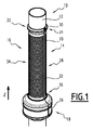
無線標識システム10が図1に示されている。
A
空路、鉄道路、水路、道路または歩行者路の交通における標識は、固定のもしくは浮遊のマークのセットを参照するか、またはすべての手段、特に光手段を使用して、危険の信号を送るもしくは続く経路を示すために載置された標識を参照する。 Signs in air, rail, water, road or pedestrian traffic may refer to a set of fixed or floating marks, or signal danger using all means, especially light means, or Reference is made to the sign placed to indicate the following route.
したがって、標識との用語は、集約された散乱光源による情報の存在を示す方法を参照しており、情報の一部の表示のコントラストを改良して、これにより暗いまたは光の少ない場所においても良好な可読性を保証することを可能にしている。 Thus, the term sign refers to a method of indicating the presence of information by an aggregated scattered light source, which improves the contrast of the display of some of the information, thereby making it better in dark or low light locations It is possible to guarantee readability.
したがって、無線標識システム10は、特定の位置、危険の発生した場所、アクセスポイント、または特定の情報を示すことが可能である。
Therefore, the
無線標識システム10は、タワー12およびタワー12に搭載された無線標識装置14を含んでいる。
The
タワー12は円筒形である。
The
定義により、円筒形は円筒面および2つの厳密に平行な平面により形成された立体である。円筒面は母線と称される直線により形成された空間内の面であり、母線は案内曲線と称される閉じた平面曲線を描いた動点を通過し、固定の方向を維持している。案内曲線により形成された面は、これ以降円筒のベースと称される。 By definition, a cylinder is a solid formed by a cylindrical surface and two strictly parallel planes. The cylindrical surface is a surface in a space formed by a straight line called a generating line, and the generating line passes through a moving point describing a closed plane curve called a guiding curve and maintains a fixed direction. The surface formed by the guiding curve is hereafter referred to as the base of the cylinder.
図1の例によれば、母線はいわゆる軸方向に沿って延びている。図1において、軸方向は軸Zにより象徴されている。 According to the example of FIG. 1, the generatrix extends along the so-called axial direction. In FIG. 1, the axial direction is symbolized by the axis Z.
さらに、タワー12のベースは任意の形状を備え得る。
Further, the base of the
図1の場合、タワー12のベースは円盤形状である。
In the case of FIG. 1, the base of the
タワー12にベースの直径は、例えば70mm(ミリメートル)〜300mmの間に含まれている。
The diameter of the base of the
代替的に、タワー12のベースは楕円形である。
Alternatively, the base of
さらに別の代替案によれば、タワー12のベースは長方形、正方形、三角形、または4つよりも多い辺を備えた多角形である。五角形または六角形は、4つよりも多い辺を備えた多角形の例である。
According to yet another alternative, the base of
代替的に、タワー12は円錐形である。
Alternatively, the
定義により、円錐は平面により、および母線と称される直線により形成された立体であり、母線は、頂点と称される固定点および案内曲線と称される曲線を描いた動点を通過し、平面は頂点を含まず、すべての母線に割線されている。 By definition, a cone is a solid formed by a plane and by a straight line called a generating line, which passes through a fixed point called the vertex and a curved moving point called the guiding curve, The plane contains no vertices and is secant to all buses.
図1の例によれば、タワー12は中空であり、すなわちタワー12は空の内側空間を形成したチューブ形状である。
According to the example of FIG. 1, the
無線標識装置14は周囲を照らすことが可能であり、タワー12は、無線標識装置14のためのサポートとして寄与している。
The
特定の一実施例によれば、無線標識装置14は光の情報を放出することが可能である。
According to one particular embodiment, the
代替的に、無線標識装置14は、例えば経路を示すような視覚情報の一部を示すことを目的とされている。
Alternatively, the
一実施例によれば、無線標識装置14は、情報の特定の一部を示すことを目的とされている。
According to one embodiment, the
代替的に、無線標識装置14は、危険の存在の警告を提供することを目的とされている。
Alternatively, the
無線標識装置14は、電気エネルギ発生ユニット16および光エネルギ発生ユニット18を含んでいる。簡素化の理由により、これ以降電気エネルギ発生ユニットは単に電気ユニット16と称され、一方で光エネルギ発生ユニット18は光ユニット18と称される。
The
電気ユニット16は電気エネルギを発生して、光ユニット18に電力供給することが可能である。
The
電気ユニット16は、太陽光発電モジュール20およびタワー12上に太陽光発電モジュール20を保持するための支持体22を含んでいる。
The
定義により、太陽光発電モジュールは太陽光センサまたは太陽光パネルである。さらに、太陽光発電モジュールは、互いに電気的に接続された一式の太陽光発電セルを含んだ交流発電機であり、モジュールは太陽エネルギからの電気を供給することに寄与している。 By definition, a photovoltaic module is a solar sensor or a solar panel. Furthermore, a photovoltaic module is an alternator that includes a set of photovoltaic cells electrically connected to each other, and the module contributes to supplying electricity from solar energy.
図1の実施例によれば、太陽光発電モジュール20は有機タイプの太陽光発電モジュールである。このことは、起電モジュールが特定の太陽光発電セル、少なくとも有機分子から構成された活性層を含んでいることを意味している。結果的に、太陽光発電セルに関する太陽光発電効果は、半導体材料の特性を使用して得られている。
According to the embodiment of FIG. 1, the
半導体が、炭素原子と水素原子との間の共有結合、炭素原子と窒素原子との間の共有結合、または炭素原子と酸素原子との間の結合から構成されたグループに属した少なくとも1つの結合を含んでいる場合、半導体は有機体であると考えられている。 At least one bond belonging to the group consisting of a covalent bond between a carbon atom and a hydrogen atom, a covalent bond between a carbon atom and a nitrogen atom, or a bond between a carbon atom and an oxygen atom; If it contains, the semiconductor is considered organic.
有機太陽光発電モジュールは、互いに隣り合い且つ直列または並列に接続された、少なくとも2つの個別化された太陽光発電セルを具備したアセンブリである。有機太陽光発電モジュールの形式は、基板上に積層されたフィルムストリップの積層パターンを含んでいる。 Organic photovoltaic modules are assemblies comprising at least two individualized photovoltaic cells adjacent to each other and connected in series or in parallel. The type of organic photovoltaic module includes a stacking pattern of film strips stacked on a substrate.
フィルムは、比較的薄い厚さを有する材料または混合材料から形成された均質且つ連続的な層である。比較的薄い厚さとは、500ミクロン以下の厚さを参照している。 A film is a homogeneous and continuous layer formed from a material or mixed material having a relatively small thickness. Relatively thin thickness refers to a thickness of 500 microns or less.
例えば、太陽光発電モジュールの構成は、0.5mm〜4.5mmの間に含まれた幅の中間帯領域により分離された、9.5mm〜13.5mmの間に含まれた幅を有し、バンドおよび中間帯領域の全幅は14mmであるストリップを含んでいる。モジュールは、異なった被覆または印刷方法を使用した複数層の積層から形成されている。 For example, the configuration of a photovoltaic module has a width comprised between 9.5 mm and 13.5 mm, separated by an intermediate zone region having a width comprised between 0.5 mm and 4.5 mm. , The band and the intermediate zone region include a strip having a total width of 14 mm. Modules are formed from multiple layers of stacks using different coating or printing methods.
有機太陽光発電モジュールの使用は、比較的薄い発電機を有することを可能にしており、比較的薄いとは500ミクロン以下、または300ミクロン以下の厚さを参照し、これにより軽量であり、切断によりそのサイズの受注生産を可能とし、モジュールの統合環境への即座の取付けを可能にした機械的柔軟性を有する。 The use of organic photovoltaic modules makes it possible to have a relatively thin generator, which refers to a thickness of less than 500 microns, or less than 300 microns, which is lighter, cut Has the mechanical flexibility to allow the module to be made to order and the module to be installed immediately in an integrated environment.
代替的に、太陽光発電モジュール20は、非晶質シリコン製の可撓性モジュールである。
Alternatively, the
図1の実施例によれば、太陽光発電モジュール20はさらに、タワー12の周囲の少なくとも一部の周りに巻き付けられることが可能である。タワー12の周囲は、タワー12の円筒面に対応している。
According to the embodiment of FIG. 1, the
好適に、図1の特別な場合において、太陽光発電モジュール20は、タワー12の全周にわたって巻き付けられている。
Preferably, in the special case of FIG. 1, the
太陽光発電モジュール20のセルは垂直軸Zに直交、すなわち水平に配置され、これにより光源(通常は太陽)が一日の経路上を移動した場合にも完全に日陰になることは無く、それにより装置14への連続的な給電を可能にしている。
The cells of the
このことは、全方向において光を収集することを可能にしている。したがって、非可撓性の技術とは異なり、太陽光発電モジュール20が一日を通して光を受容するための太陽追尾器を使用する必要がない。
This allows light to be collected in all directions. Thus, unlike inflexible technology, the
太陽光発電モジュール20の寸法は、太陽光発電モジュール20の電気的性能を決定している。結果的に、太陽光発電モジュール20の寸法は、光源18が必要とするエネルギ、および装置14が搭載された地理的場所の平均日照に基づいて決定されている。
The dimensions of the
例えば、毎時5ワットの日常的消費を有する光ユニット18に関して、太陽光発電モジュール20の平均発電量は、光源18が必要なエネルギの少なくとも2倍、すなわち毎時10ワットと考えられ、それは、その必要性が最も低い日照の日に遭遇した場合でも確実とするためである。例えば、ピークで60W/m2の太陽光発電モジュール20の電気性能レベルに関して、Z軸方向に沿って600mmの寸法が所望のエネルギ必要量に合致することが決定され得る。
For example, for a
太陽光発電モジュール20がタワー12の周りに巻き付けられた場合、太陽光発電モジュール20は、Z軸方向に沿って10mm〜1mの間に含まれた寸法を有する領域を、タワー12上に形成する。
When the
図1の実施例によれば、タワー12上の太陽光発電モジュール20により形成された領域は、Z軸方向に沿って600mmの寸法を有する。
According to the embodiment of FIG. 1, the area formed by the
例えば、約600mmの寸法の太陽光発電モジュールの450mmを使用することを考慮することが可能である。 For example, it is possible to consider using 450 mm of a photovoltaic module with dimensions of about 600 mm.
次に、太陽光発電モジュール20に関して、遠位端部24および近位端部26が形成され、遠位端部24は光ユニット18から最も遠い端部である。
Next, with respect to the
図1の特別な場合においては、各端部24および26は、タワー12の曲線(目の前の場合においては円)に一致している。
In the special case of FIG. 1, each
支持体22は、タワー12の周囲の少なくとも一部上に、好適に図1に示されたようにタワー12の全周上に巻き付けられた太陽光発電モジュール20を保持することが可能である。
The
支持体22は、太陽光発電モジュール20、リング30、および保持要素32、34を保護することが可能である。
The
保護壁28は、外側から太陽光発電モジュール20を隔離することが可能である。特に、保護壁28は、太陽光発電モジュール20を損傷し得る悪天候から、太陽光発電モジュール20を保護することが可能である。
The
図1の実施例によれば、保護壁28は太陽光発電モジュール20の全体を覆い、これにより太陽光発電モジュール20上に配置された被覆層を形成している。
According to the embodiment of FIG. 1, the
さらに、図示された特別な場合によれば、保護壁28はフィルムの形式を想定している。
Furthermore, according to the special case shown, the
非限定的な実施例として、保護壁28は、ポリメチルメタクリレート樹脂(PMMA)、ガラス、または透明な樹脂の中から選択された材料から形成されている。
As a non-limiting example, the
リング30は、把持リングまたは仕上げリングとして作用することが可能である。
リング30は、太陽光発電モジュール20の遠位端部24に配置されている。
リング30は、Z軸方向に直交した平面内において延びている。そのような平面は、記載の連続性において径方向面として記載されている。
The
リング30は円形である。
図1の実施例によれば、リング30はプラスチックから形成されている。
According to the embodiment of FIG. 1, the
別の実施形態によれば、リング30は金属、特に鋼またはアルミニウムから形成されている。
According to another embodiment, the
代替的に、リング30は、ゴムまたは樹脂のような可撓性材料から形成されている。
Alternatively,
2つの保持要素32、34は、リング30を光ユニット18に接続することが可能である。
Two holding
さらに、2つの保持要素32、34は、保護壁28のシール機能を発揮させることが可能である。
Furthermore, the two holding
図1の実施例によれば、2つの保持要素32、34は、太陽光発電モジュール20の遠位端部26と、太陽光発電モジュール20の近位端部と、の間に延びている。
According to the embodiment of FIG. 1, the two holding
図1に示されたように、2つの保持要素32、34は直線的である。
As shown in FIG. 1, the two holding
さらに、2つの保持要素32、34は、タワー12に関して径方向の反対側に配置されている。
Furthermore, the two holding
例えば、2つの保持要素32、34の各々は可撓性材料から形成されている。概して、ゴムまたはシリコーンシールと考えることが可能である。
For example, each of the two holding
光ユニット18は、タワー12上に締結されるように構成されている。
The
光ユニット18は、タワー12の周囲環境のために発光機能を発揮することが可能である。
The
光ユニット18は、電気エネルギ管理機能および電気エネルギ貯蔵機能を発揮することも可能である。
The
光ユニット18は、ハウジング36、蓄電部材38、調整部材40、および光放出部材42を含んでいる。
The
図2においては、蓄電部材38および調整部材40は、可読性の理由により破線によって示されており、それらはハウジング36の中央に配置されている。図2に示された位置は純粋に概略的であり、蓄電部材38および調整部材40がタワー12の周囲であることを、当業者は理解するだろう。
In FIG. 2, the
ハウジング36は、本体44、保護壁46、蓄電部材38、および調整部材40を含んでいる。
The
本体44は、上部48、下部50、および上部48と下部50とにより形成された中間部52を備えている。
The
中間部52は、円形ベースを備えた円筒形状である。円筒の母線は、少なくとも150mmの高さを超えて延び、好適に150mm〜250mmの間に含まれている。好適に、円筒の母線の高さは、200mmに等しい。
The
本体44は、第1部分54および第2部分56の二部品を備えている。
The
好適に、第1部分54および第2部分56は略同一であり、これにより各部分54、56は半円筒形である。
Preferably,
第1部分54は第2部分56に接続されている。
The
例えば、図3に示されたように、第1部分54は、ネジ−ナットシステムにより第2部分56に接続されている。
For example, as shown in FIG. 3, the
代替的に、「クリップシステム」または「雄」−「雌」埋め込みシステムも考慮され得る。 Alternatively, a “clip system” or “male”-“female” implantation system may also be considered.
一実施形態においては、第1部分54は、Z軸方向に直交した方向において、「雄」−「雌」埋め込みシステムにより第2部分56に接続されるように構成されている。
In one embodiment, the
代替的に、第1部分54と第2部分56との間の機械的接続に寄与したシステムは、調整部材40と蓄電部材38との間の電気的接続を確立することも可能にしている。この目的のために、例えば第1部分54および第2部分56の各々は導電性トラック部を含み、2つの導電性トラック部は、機械的接続の確立により、導電性トラックを形成する。
Alternatively, the system that contributed to the mechanical connection between the
第1部分54と第2部分56とが接続された場合、本体44は、タワー12に相補的な形状を備えた中央凹部58を形成する。
When the
代替的に、凹部58は2つの部分54、56のうちの1つのみ、例えば第2部分により形成されている。
Alternatively, the
本体44はプラスチック材料製である。
The
別の実施例によれば、本体44は金属、例えば鋼またはアルミニウムから形成されている。
According to another embodiment,
別の実施例によれば、本体44はゴムまたは樹脂のような可撓性材料から形成されている。
According to another embodiment,
上部48はシールを含んでいる。
シールは、可撓性ゴムシート、ゴムプロファイル、またはシリコーンシールのような材料から形成されている。 The seal is formed from a material such as a flexible rubber sheet, a rubber profile, or a silicone seal.
中間部52は、光放出部材42、光放出部材42の第1保護壁62、保護壁64のシール、および管理部材の保護壁66を含んでいる。
The
代替的に、中間部52は、少なくとも2つの光放出部材42、および少なくとも1つの、光放出部材42の保護壁を含んでいる。ある場合では、中間部52は隆起されて、これによりすべての光放出部材42を保護している。
Alternatively, the
別の代替案によれば、保護壁62は画像または文章を含み、これらの画像または文章は使用者の注意を惹きつける情報に対応している。
According to another alternative, the
第1保護壁62は、ポリカーボネイト材料製である。
The first
第1保護壁62は、代替的にガラス製である。
The first
別の実施例によれば、第1保護壁62は、透明な樹脂製である。
According to another embodiment, the first
第2保護壁66はプラスチック製であり、プラスチックは不透明であっても不透明でなくてもよい。
The second
代替的に、第2保護壁66はポリカーボネイト製である。
Alternatively, the second
別の実施例によれば、第2保護壁66はガラス製である。
According to another embodiment, the second
さらに別の実施例によれば、第2保護壁66は、鋼またはアルミニウムのような金属製である。
According to yet another embodiment, the second
蓄電部材38は、電気ユニット16により発生した電気エネルギを蓄積することが可能である。
The
例えば、蓄電部材38はリチウムイオン電池である。
For example,
蓄電部材38の容量は、光ユニット18のエネルギ必要量に基づいて決定されている。
The capacity of the
蓄電部材38の容量は、例えば2000mAh(ミリアンペアアワー)である。
The capacity of
調整部材40は、蓄電部材38の蓄電を調整することが可能である。
The
一実施例として、調整部材40は、電池の充電状態(SOC)を測定することが可能である。
As an example, the
光放出部材42は、蓄電部材38により電力供給されている。
The
図1の実施例によれば、光放出部材42は、ハウジング36の周囲を越えて延びている。
According to the embodiment of FIG. 1, the
図1の実施例によれば、光放出部材42は、シールが配置されてシールに寄与した位置を除いて、実質的にハウジング36の全周を越えて延びたストリップ光源である。
According to the embodiment of FIG. 1, the
例として、限定的ではないが、光放出部材42は、一式の発光ダイオード(LED)である。
By way of example, and not limitation,
例えば、発光ダイオードは、タワー12を取り囲んだ線に沿ってZ軸方向の周りに分配されている。一実施形態によれば、前述の線はZ軸方向に直交した平端な円盤を形成している。
For example, the light emitting diodes are distributed around the Z axis along a line surrounding the
一実施形態によれば、発光ダイオードは線に沿って角度的に均等に分配されており、すなわち各発光ダイオードは2つの最も接近した発光ダイオードから等距離にある。換言すると、2つの連続した発光ダイオードおよびタワー12の軸により形成された角度の各々は、他のそのようにして形成された角度と等しい。
According to one embodiment, the light emitting diodes are evenly distributed angularly along the line, ie each light emitting diode is equidistant from the two closest light emitting diodes. In other words, each of the angles formed by the two consecutive light emitting diodes and the axis of the
発光ダイオードは、例えばハウジング36の周に沿って分配され、これにより360°にわたってタワー12を取り囲んでいる。したがって、視認者に対するZ軸方向の周りのハウジング36の向きにかかわらず、少なくとも1つの発光ダイオードがいかなる場合でも視認者に対して可視的である。
The light emitting diodes are distributed, for example, along the circumference of the
代替的に、発光ダイオードは、Z軸方向の周りにタワー12を取り囲んだ少なくとも2つの線に沿って分配されている。
Alternatively, the light emitting diodes are distributed along at least two lines surrounding the
例えば、発光ダイオードは、各線に沿って角度的に均等に分配されている。同一の線内の2つの連続した発光ダイオードおよびタワー12の軸により形成された角度は、角度値を有する。角度値は、例えば考慮された各線に関して同一である。代替的に、少なくとも1つの線に関連した角度値は、少なくとも1つの他の線に関連した角度値とは異なっている。
For example, light emitting diodes are evenly distributed angularly along each line. The angle formed by two consecutive light emitting diodes in the same line and the axis of the
一実施形態によれば、各線の発光ダイオードは、ハウジング36の周の一部に沿って分配されている。
According to one embodiment, the light emitting diodes of each line are distributed along a portion of the circumference of the
例えば、各線の発光ダイオードは、60°〜180°の間に含まれた角度上に分配されている。このことは、線に属した第1発光ダイオードを横切った第1セグメントおよびタワー12の軸、ならびに同じ線に属する第2発光ダイオードを横切った第2セグメントおよびタワー12の軸により形成された角度が、60°〜180°の間に含まれ、2つの考慮された発光ダイオードは、それらの間の最大の角度を形成した発光ダイオードであることを意味している。
For example, the light emitting diodes of each line are distributed over angles comprised between 60 ° and 180 °. This means that the angle formed by the axis of the first segment and the
結果として、装置14は方向の信号伝達に適している。このことは、発光ダイオードが、観測者に対してハウジング36の所定の向きに関してのみ視認可能であることを意味している。
As a result, the
装置14の動作がここに記載される。
The operation of the
作動中に、装置14は完全に自立的であり、それは、日中は太陽が太陽光発電モジュールを照らすためである。太陽光発電モジュール20は、太陽からの光エネルギを電気エネルギに変換する。
In operation, the
太陽光発電モジュール20により生じる電気エネルギは、次に蓄電部材38に蓄電される。
The electric energy generated by the photovoltaic
(例えば夜に)点灯が所望された場合、蓄電部材38は光放出部材42に電力供給する。そして、光放出部材42は発光する。
If lighting is desired (eg, at night),
装置14は、比較的軽量である利点を有する。装置14の総重量は5キログラム、概して4キログラム付近である。
光放出部材42の電力供給は、さらに自立的且つ再生可能でありそれは太陽エネルギを使用しているためである。
The power supply of the
装置14は、任意の形状(円形ベース、楕円形ベース、または多角形ベースを備えた筒形)を備えた任意のタイプのタワー12にさらに適合している。
さらに、装置14は任意の高さに搭載可能である。
Further, the
そのような装置14の配置は、装置14が搭載されたタワー12に任意の影響および/または任意の劣化を与える原因とならない。
Such an arrangement of the
タワー12上の太陽光発電モジュール20の配向に関係なく、光は太陽光発電モジュール20により捕捉される。
Regardless of the orientation of the
さらに、無線標識および光の対照は、システム10を見る任意の位置の人に関して視認可能である。
Further, the radio beacon and light contrast are visible for a person at any location looking at the
さらに、装置14は、特に多様な壁により外側からの攻撃に対して保護されている。
Furthermore, the
さらに、タワー12上への搭載および取外しは容易であり、このことは装置14の保守を容易にしている。
Further, installation and removal on the
一例として、この容易な搭載および/または取り外しは、タワー12への装置の搭載に関する方法と共に図示され得る。
By way of example, this easy mounting and / or removal may be illustrated with a method for mounting the device to the
例えば、そのような方法は以下のステップを含んでおり、それらは、タワー12に太陽光発電モジュール20を巻き付けるステップ、ハウジング36の2つの部品54および56を組み立て、ハウジング36をタワー12に締結するステップ、ハウジング36の2つの部品54および56の一方に収容された蓄電部材38を、ハウジング36の2つの部品54および56の他方に収容された調整部材40と電気的に接続するステップ、である。
For example, such a method includes the following steps: winding the
この方法は、太陽光発電モジュール20と調整部材40との間の電気的接続を生じさせるステップ、光放出部材42と調整部材40との間の電気的接続を生じさせるステップ、支持体22を組み立てるステップ、支持体22をハウジング36内に締結するステップ、および支持体の一部である(複数の)リングを締め付けるステップ、も含んでいる。
The method includes the steps of creating an electrical connection between the
したがって、その方法は、従来技術の方法よりもはるかに容易に実行されることが明確に示されており、それは、装置14に特有の要素のみが、装置14のタワー12への搭載に組み込まれているためである。
Thus, it is clearly shown that the method is much easier to carry out than the prior art methods, in that only the elements specific to the
さらに、装置14は容易に設定可能である利点を有する。
Furthermore, the
そのような設定可能性は装置14の進化を特に可能にしている。場合により、そのような進化は異なった形式をとる。特に、光ユニット18の数の変化が考えられ、各光ユニットは異なった機能を発揮することが可能である。概して、1つの光ユニット18は無線標識機能を発揮し、一方で他の光ユニット18は情報光機能を発揮する。
Such a configurable possibility particularly allows the evolution of the
別の実施例によれば、電気ユニット16の数の変化は、(複数の)光ユニット18のエネルギの必要性に適合可能である。そのような適合は、特に光ユニット18を追加した場合の有用性、または装置14の(複数の)光ユニット18のエネルギの必要性の初期的な少量化となる。
According to another embodiment, the change in the number of
装置14の設定可能性は、例えば図5〜図7に示されている。
The configurable possibilities of the
図5の実施例においては、装置14は、図1の実施例のような単一の電気ユニット16に代えて、2つの電気ユニット16を含んでいる。
In the embodiment of FIG. 5, the
図示された構成においては、光ユニット18は2つの電気ユニット16の間に配置されている。
In the configuration shown, the
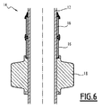
図6の実施例においては、装置14は、図1の実施例のような単一の電気ユニット16に代えて、2つの電気ユニット16を含んでいる。
In the embodiment of FIG. 6, the
図示された構成においては、2つの電気ユニット16は光ユニット18に対して同じ側に配置されている。
In the configuration shown, the two
図7の実施例においては、装置14は、図1の実施例のような単一の光ユニット18に代えて、2つの光ユニット18を含んでいる。
In the embodiment of FIG. 7, the
図示された構成においては、電気ユニット16は2つの光ユニット18の間に配置されている。
In the configuration shown, the
装置14のそのような設定可能性は、異なったユニット14および16が、一方のユニット14、16の突出部を別のユニット14、16の対応した溝内に嵌めこむことにより結合され得るということによって可能とされている。
Such a configurable possibility of the
これまでに説明したように、装置14の設定可能性は、すでにタワー12の所定の位置にある装置14の使用による変化の必要性に容易に適応することが可能である。例えば、変化の必要性は、タワー12の機能における変化および/またはエネルギの必要性の変化に対応している。新しい必要性への適応は、装置14の単純な進化により実行され得る。例えば、追加の光ユニット18は、発生する光の量の増大のために追加される。
As explained above, the configurable nature of the
さらに、一代替案によれば、装置14は複数の光放出部材を含み、これらの光放出部材の1つは、ハウジング36の周囲上に延びた光放出部材42である。
Further, according to one alternative, the
図8は、本発明による装置14の別の例示的な実施形態を示している。図1の第1実施形態と同一の要素は、再度は記載されていない。差異のみが示されている。
FIG. 8 shows another exemplary embodiment of the
上部48は外側面68および内側面70を備えている。
The
上部48は、外側面68によっておよび内側面70によって、Z軸に直交した面内に形成されている。
The
上部48は第1トラック72、第2トラック74、第1コネクタ76、第2コネクタ78、およびシール79を含んでいる。
The
外側面68および内側面70のうち、内側面70は、無線標識装置14がタワー12に搭載された場合に、タワー12に最も接近した面である。
The inner side surface 70 of the outer side surface 68 and the inner side surface 70 is the surface closest to the
タワー12が円筒形である場合、無線標識装置14がタワー12に搭載された際に、内側面70はタワー12と接触する。
If the
内側面70は第1部分80、ショルダ82、および第2部分84を備えている。
The inner surface 70 includes a
第1部分80および第2部分84のうち、第1部分80はZ軸方向に沿って中間部52に最も接近している。
Of the
タワー12が円筒形である場合、無線標識装置14がタワー12に搭載された際に、第1部分80はタワー12に接触して支えるように設けられている。
When the
例えば、第1部分80は円形ベースを備えた円筒形状であり、第1部分80の母線は、Z軸方向に平行である。
For example, the
第1直径D1は、第1部分80に関して定義されている。第1直径D1は、例えば70mm〜300mmの間に含まれている。
The first diameter D1 is defined with respect to the
ショルダ82は、第1部分80および第2部分84により、Z軸方向に直交した平面内に形成されている。
The
円筒部の場合、「ショルダ」は、その部分の母線に直交した面を示した部分の断面の変化を参照している。 In the case of a cylindrical portion, “shoulder” refers to a change in the cross section of a portion showing a plane orthogonal to the generatrix of that portion.
ショルダ82は円筒ベースを備えた環状であり、すなわちショルダ82は、同一平面上且つ同心の、異なった直径を有する2つの円により形成された平坦面である。ショルダ82はZ軸方向に直交している。
The
ショルダ82は、太陽光発電モジュール20および光ユニット18がタワー12に搭載された場合に、太陽光発電モジュール20の近位端部26がZ軸方向に沿ってショルダ82に接触して支持されるように設けられている。
When the
第1部分80および第2部分84のうち、第2部分84はZ軸方向に沿って中間部52から最も離れている。
Of the
第2部分84は円形ベースを備えた円筒形であり、第2部分84の母線はZ軸方向に平行である。
The
第2直径D2は、第2部分84に関して定義されている。
The second diameter D2 is defined with respect to the
第2直径D2は、第1直径D1よりも完全に大きい。第2直径D2は、例えば75mm〜310mmの間に含まれている。 The second diameter D2 is completely larger than the first diameter D1. The second diameter D2 is included, for example, between 75 mm and 310 mm.
第2部分84は、ショルダ82およびシール79により、Z軸方向に沿って形成されている。
The
第2部分84は、太陽光発電モジュール20および光ユニット18がタワー12に搭載された場合に、太陽光発電モジュール20の近位端部26がZ軸方向に直交した平面内において、第2部分84により取り囲まれるように設けられている。
When the
第1トラック72は、導電性ストリップである。例えば、第1トラック72は銅のような金属材料から形成されている。代替的に、第1トラック72は、アルミニウムまたは銀のような別の導電性材料から形成されている。
The
第1トラック72は第2部分84により支持されている。
The
第1トラック72は、第1長さL1、第1幅l1、および第1厚さe1を有する。
The
第1長さL1は、第2部分84の周囲に沿って測定されている。換言すると、第1長さL1は、Z軸に直交した平面上への第1トラック72の直交投影の、湾曲した全体により測定された長さである。
The first length L1 is measured along the periphery of the
第1長さL1は、第2直径D2と数値πとの積の半分以上の大きさである。 The first length L1 is at least half the product of the second diameter D2 and the numerical value π.
第1幅l1はZ軸方向に沿って測定されている。第1幅l1は均一であり、すなわち第1幅l1は第1トラック72のすべての位置において同一である。第1幅l1は2mm〜3mmの間に含まれている。
The first width 11 is measured along the Z-axis direction. The first width 11 is uniform, that is, the first width 11 is the same at all positions of the
第1厚さe1は径方向に沿って測定されている。「径方向」は、第2部分84の軸に直交し且つ第2部分84の軸を横断したセグメントに平行な方向を参照しており、その位置において厚さが測定されている。第1厚さe1は均一である。第1厚さe1は、0.5mm〜2mmの間に含まれている。
The first thickness e1 is measured along the radial direction. "Radial" refers to a direction perpendicular to the axis of the
一実施形態によれば、第1トラック72は第2部分84に準拠しており、すなわち第1トラック72は第2部分84と接触して、第2部分84の形状と合致している。
According to one embodiment, the
例えば、第1トラック72は環状ベースを備えた円筒であり、第1トラック72の軸はZ軸方向に平行である。
For example, the
環状または円形ベースを備えた円筒の軸は、円筒の母線に平行な且つ円筒のガイド曲線を形成した円または環の中心を縦走した直線であるとして定義されている。 The axis of a cylinder with an annular or circular base is defined as being a straight line parallel to the generatrix of the cylinder and traversing the center of the circle or annulus forming the cylindrical guide curve.
第1トラック72は、例えば2つのトラック部分から形成され、各トラック部分は、第1部分54および第2部分56の一方により支持されている。
The
第2トラック74は導電性ストリップである。例えば、第2トラック74は銅のような金属材料から形成されている。代替的に、第1トラック72はアルミニウムまたは銀のような別の導電性材料から形成されている。
The
第2トラック74は第2部分84により支持されている。
The
第2トラック74は第2長さL2、第2幅l2、および第2厚さe2を有する。
The
第2長さL2は、第2部分84の周囲に沿って測定されている。換言すると、第2長さL2は、Z軸方向に直交した平面上への第2トラック74の直交投影の、湾曲した全体により測定された長さである。
The second length L2 is measured along the periphery of the
第2長さL2は、第2直径D2と3.14にほぼ等しい数値πとの積の半分以上の大きさである。 The second length L2 is at least half as large as the product of the second diameter D2 and a value π substantially equal to 3.14.
第2幅l2はZ軸方向に沿って測定されている。 The second width l2 is measured along the Z-axis direction.
第2幅l2は均一であり、すなわち第2幅l2は、第2トラック74のすべての位置において同一である。第2幅l2は2mm〜10mmの間に含まれている。
The
第2厚さe2は、Z軸方向に直交した方向において測定されている。第2厚さe2は均一である。第2厚さe2は0.5mm〜2mmの間に含まれている。 The second thickness e2 is measured in a direction orthogonal to the Z-axis direction. The second thickness e2 is uniform. The second thickness e2 is included between 0.5 mm and 2 mm.
第2トラック74は第2部分84に準拠している。例えば、第2トラック74は環状ベースを備えた円筒であり、第2トラック74の軸はZ軸方向に平行である。
The
例えば、第2トラック74は2つのトラック部分の結合により形成されており、各トラック部分は第1部分54および第2部分56の一方により支持されている。
For example, the
第2トラック74は、第1トラック72とショルダ82との間の挿入されている。
The
第2トラック74は、第1トラック72に電気的に接続されていない。
The
例えば、第1トラック72および第2トラック74は互いに平行であり、第1トラック72と第2トラック74との間の距離はZ軸方向に沿って測定され、1mm以上の大きさである。
For example, the
第1コネクタ76は、第1トラック72を蓄電部材38または調整部材40に電気的に接続するように構成されている。
The
第2コネクタ78は、第2トラック74を蓄電部材38または調整部材40に電気的に接続するように構成されている。
The
シール79は、第1トラック72および第2トラック74を上部48の外側から隔離するように構成されている。
The
シール79は、上部48と太陽光発電モジュール20との間にシールを設けるように構成されている。特にシール79は、太陽光発電モジュール20の外側に沿って下向きの水流が、第1トラック72または第2トラック74に到達することを防止するように構成されている。
The
太陽光発電モジュール20は、陽極および陰極を含んでいる。
The
太陽光発電モジュール20は、太陽光発電モジュール20が太陽に照射された場合に、陽極と陰極との間に電位差を与えるように構成されている。
The solar
近位端部26は、図8において透明であるように示されている。
支持体22は第3コネクタ86および第4コネクタ88を含んでいる。
The
第3コネクタ86および第4コネクタ88の各々は、支持体22に締結されている。例えば第3コネクタ86および第4コネクタ88の各々は、支持体22に接着されている。代替的に、第3コネクタ86および第4コネクタ88の各々は、支持体22の剛体部分に内包されている。
Each of the
第3コネクタ86は、第1トラック72を陽極および陰極のうちの一方に電気的に接続するように構成されている。
The
第4コネクタ88は、第2トラック74を陽極および陰極のうちの他方に電気的に接続するように構成されている。
The fourth connector 88 is configured to electrically connect the
例えば、第3コネクタ86および第4コネクタ88の各々は、ケーブルにより対応した電極に接続されている。接続ケーブルはコネクタ86、88および対応した電極に例えば溶接されている。
For example, each of the
代替的に、第3コネクタ86および第4コネクタ88の各々は、フレキシブル印刷回路基板により対応した電極に接続されている。
Alternatively, each of
第3コネクタ86および第4コネクタ88の各々は、太陽光発電モジュール20とその支持体22とが上部48に対してZ軸方向周りに相対回転可能であるように構成されている。
Each of the
例えば、第3コネクタ86および第4コネクタ88の各々は、太陽光発電モジュール20と上部48とのZ軸方向周りの相対回転の際に、弾性変形するように構成されている。
For example, each of the
図8の実施例によれば、第3コネクタ86および第4コネクタ88の各々は、長方形金属舌片から形成されて、基準を形成するように曲げられている。
According to the embodiment of FIG. 8, each of the
第3コネクタ86および第4コネクタ88の各々は、金属材料から形成されている。例えば、第3コネクタ86および第4コネクタ88の各々は、導電性材料から形成されている。導電性材料は、例えば銅、銀、およびアルミニウムから成るセットから選択されている。
Each of the
第3コネクタ86および第4コネクタ88の各々は、第3部分90、第4部分92、第5部分94、および第6部分96を含んでいる。
Each of the
第3コネクタ86および第4コネクタ88の各々は、第2部分84の周囲に沿って測定された幅を有し、その幅は2mm〜10mmの間に含まれている。
Each of the
各第3部分は平行六面体である。第3部分はZ軸方向に沿って測定された長さを有し、その長さは20mm〜50mmの間に含まれている。 Each third part is a parallelepiped. The third portion has a length measured along the Z-axis direction, the length being comprised between 20 mm and 50 mm.
太陽光発電モジュール20および光ユニット18がタワー12に搭載された場合、各第3部分90は近位端部26とタワー12との間に挿入される。
When the
各第4部分92は平行六面体である。各第4部分92は、第3部分90および第5部分94により形成されている。各第4部分92は、対応した第3部分90に直交している。各第4部分92は、Z軸方向に直交している。各第4部分92は径方向に測定された長さを有し、その長さは2mm〜10mmの間に含まれている。
Each
太陽光発電モジュール20および光ユニット18がタワー12に搭載された場合、各第4部分92は近位端部26とショルダ82との間に挿入される。
When the
太陽光発電モジュール20および光ユニット18がタワー12に搭載された場合、各第5部分94は近位端部26と第2部分84との間に挿入される。
When the
各第5部分94は、第1縁部98および第2縁部100により形成されている。
Each fifth portion 94 is formed by a
各第1縁部98は、対応した第4部分92および第5部分94の両方に属している。
Each
各第2縁部100は、対応した第5部分94および第6部分96の両方に属している。
Each
各第3コネクタ86および各第4コネクタ88に関して、径方向における第2部分84の軸からの最遠位置は、対応した第2縁部100に属している。換言すると、第2部分84の軸を含み且つ第1縁部98を第2縁部100に接続した平面内に含まれたセグメントは、同一平面内に含まれた第4部分92のセグメント共に、90°よりも完全に大きい角度を形成している。考えられる角度は、2つの考えられるセグメントにより形成された2つの角度のうちで最小である。
For each
各第2縁部100は、第1トラック72および第2トラック74のうちの1つに接触して位置している。
Each
第5部分94は、第3部分90、第4部分92、および第6部分96のそれぞれと共に、近位端部26を少なくとも部分的に取り囲んだ凸状空間を形成している。
Fifth portion 94, together with each of
第6部分96は端部を備えている。第6部分96の端部は第2縁部100の反対側である。
The
第6部分96は第2縁部100により、および第6部分96の端部により形成されている。
The
第6部分96の端部は、近位端部26に接触して位置している。
The end of the
したがって、各第6部分96は、対応した電極および対応したトラック72、74を電気的に接続するように構成されている。
Accordingly, each
第6部分96および第5部分94は、太陽光発電モジュール20および光ユニット18がタワー12に搭載された場合に、第6部分96および第5部分94が弾性力を発生して、第2縁部100が対応したトラック72、74を押圧するように構成されている。
When the
例えば、太陽光発電モジュール20および光ユニット18がタワー12に搭載された場合に、第1トラック72および第2トラック74の各々は第2縁部100に対応した力をかけて、対応した第6部分96および第5部分94を弾性変形させる。
For example, when the
そのとき、装置14は、光ユニット18と太陽光発電モジュール20との間の相対回転を許容し、一方でそれらの間の電気的接続を維持している。
At that time, the
したがって、装置14は、光ユニット18の配向を変化させることなく太陽光発電モジュール20の配向、特に太陽光発電モジュールの太陽に対する好適な配向の変化を可能にしている。
Thus, the
さらに、太陽光発電モジュール20の間の電気的接続はより小さい体積を有し、より生産が容易であり、それは電力ケーブルの接続を想定しておらず、近位端部26のショルダ82に対する容易な位置決めは、太陽光発電モジュール20と光ユニット18との間の電気的接続を可能にしているためである。
In addition, the electrical connection between the
本発明による装置14の例示的な第3実施形態が、図9に示されている。図8の第2実施形態と同一の要素は、再度は記載されていない。差異のみが図示されている。
A third exemplary embodiment of the
第2部分84は、第1ロッド102および第2ロッド104を含んでいる。
The
各ロッド102、104は、光ユニット18がタワー12に搭載された場合に、第2部分84からタワー12に向かって延びた連続的なストリップ材料である。
Each
一実施形態によれば、各ロッド102、104は少なくとも180°にわたってタワー12を取り囲んでいる。
According to one embodiment, each
例えば、各ロッド102、104は平行六面体セクションを備えている。
For example, each
第1ロッド102は、第1トラック72と第2トラック74との間に挿入されている。
The
ロッド102、104は互いに協働して、光ユニット18と太陽光発電モジュール20との間の相対回転の際に第3コネクタ86をガイドし、これにより回転の際に第3コネクタ86が第1トラック72と電気的に接触したままとなるように構成されている。
The
第1ロッド102はショルダ82と協働して、光ユニット18と太陽光発電モジュール20との間の相対回転の際に第4コネクタ88をガイドし、これにより回転の際に第4コネクタ88が第1トラック72と電気的に接触したままとなるように構成されている。
The
第3コネクタ86および第4コネクタ88の各々は円形ベースを備えた円筒形であり、第3コネクタ86および第4コネクタ88の各々の母線は、第2部分84の径方向に平行である。
Each of the
第3コネクタ86および第4コネクタ88の各々は、2mm〜10mmの間に含まれた直径を有する。
Each of the
第3コネクタ86および第4コネクタ88の各々は、ベース106および接触端部108を備えている。第3コネクタ86および第4コネクタ88の各々は、ベース106および接触端部108により第2部分84の径方向に形成されている。
Each of the
各ベース106は、対応したコネクタ86、88を近位端部26に締結するように構成されている。
Each
各接触端部108は半球形である。各接触端部108は、太陽光発電モジュール20および光ユニット18がタワー12に搭載された場合に、対応したトラック72、74に接触して位置するように設けられている。
Each
次に、ロッド102および104は、電気ユニット16を光ユニット18に強固に固定することを可能にしている。ロッド102および104は、モジュール20およびその支持体22をハウジング36に対して所定の位置に維持することに寄与している。
Next, the
さらに、ロッド102および104は、第3コネクタ86および第4コネクタ88の所定の位置におけるより良好な保守も可能にしており、したがって、第3コネクタ86および第4コネクタ88とトラック72および74との間のより信頼性の高い電気的接続を可能にしている。
Further, the
第3コネクタ86および第4コネクタ88とトラック72および74との間の接触面も、強化されている。
The contact surfaces between the third and
別の例示的な装置14によれば、装置はタワー12を把持するために設けられた締結バンドを含んでいる。締結バンドがタワー12を把持した場合、例えば締結バンドはハウジング36のための支持体を形成する。
According to another
そのとき、装置14は非円筒形のタワー、特に円錐形タワーに締結されることに特に適したものとなる。
The
10 ・・・無線標識システム
12 ・・・タワー
14 ・・・無線標識装置
16 ・・・電気エネルギ発生ユニット
18 ・・・光エネルギ発生ユニット
20 ・・・太陽光発電モジュール
22 ・・・支持体
24 ・・・遠位端部
26 ・・・近位端部
28 ・・・保護壁
30 ・・・リング
32、34 ・・・保持要素
36 ・・・ハウジング
38 ・・・蓄電部材
40 ・・・調整部材
42 ・・・光放出部材
44 ・・・本体
46 ・・・保護壁
48 ・・・上部
58 ・・・中央凹部
62 ・・・第1保護壁
66 ・・・第2保護壁
68 ・・・外側面
70 ・・・内側面
72 ・・・第1トラック
74 ・・・第2トラック
76 ・・・第1コネクタ
78 ・・・第2コネクタ
79 ・・・シール
80 ・・・第1部分
82 ・・・ショルダ
84 ・・・第2部分
86 ・・・第3コネクタ
88 ・・・第4コネクタ
90 ・・・第3部分
92 ・・・第4部分
94 ・・・第5部分
96 ・・・第6部分
98 ・・・第1縁部
100 ・・・第2縁部
102 ・・・第1ロッド
104 ・・・第2ロッド
106 ・・・ベース
108 ・・・接触端部
DESCRIPTION OF
Claims (11)
前記タワー(12)の周囲の少なくとも一部上に、好適に前記タワー(12)の全周上に巻き付けられることが可能な、少なくとも1つの太陽光発電モジュール(20)を具備した電気エネルギ発生ユニット(16)と、
前記タワー(12)に締結されるように構成された光エネルギ発生ユニット(18)であって、
−外周を備えたハウジング(36)と、
−前記電気エネルギ発生ユニット(16)により発生した電気エネルギを蓄電するための蓄電部材(38)と、
−該蓄電部材(38)の蓄電を調整するための調整部材(40)と、
−前記蓄電部材(38)により電力供給される光放出部材(42)であって、前記ハウジング(36)の外周上に延びた光放出部材(42)と、を備えた光エネルギ発生ユニット(18)と、
を含み、
前記ハウジング(36)は2つの部品(54、56)を備え、各部品(54、56)は電気的トラック部分を具備し、2つの該トラック部分は、第2部品(56)が第1部品(54)に接続された場合に、連続的なトラックを形成する
ことを特徴とする発光装置。 A light emitting device (14) mounted on a tower (12), the device comprising:
An electrical energy generating unit comprising at least one photovoltaic module (20) that can be wound on at least part of the perimeter of the tower (12), preferably all around the tower (12) (16),
An optical energy generating unit (18) configured to be fastened to said tower (12),
A housing (36) with an outer periphery;
A power storage member (38) for storing the electric energy generated by the electric energy generation unit (16);
An adjusting member (40) for adjusting the power storage of the power storage member (38);
A light emitting member (42) powered by the power storage member (38), the light emitting member (42) extending on the outer periphery of the housing (36); )When,
Only including,
Said housing (36) comprises two parts (54,56), each part (54,56) comprises an electrical track part, said two track parts being the second part (56) being the first part (54) A light emitting device which forms a continuous track when connected to the light emitting device.
該タワー(12)に搭載された請求項1〜7のいずれか一項に記載の装置(14)と、を具備していることを特徴とする無線標識システム(10)。 Tower (12),
A radio beacon system (10), characterized in that it comprises a device (14) according to any one of claims 1 to 7 mounted on the tower (12).
該タワー(12)の周囲の少なくとも一部上に、好適に前記タワー(12)の全周上に巻き付けられることが可能な、少なくとも1つの太陽光発電モジュール(20)を具備した電気エネルギ発生ユニットと、
前記タワー(12)に締結されるように構成された少なくとも1つの光エネルギ発生ユニット(18)であって、各光エネルギ発生ユニット(18)は、
−外周を備えたハウジング(36)と、
−前記電気エネルギ発生ユニット(16)により発生した電気エネルギを蓄電するための蓄電部材(38)と、
−該蓄電部材(38)の蓄電を調整するための調整部材(40)と、
−前記蓄電部材(38)により電力供給される光放出部材(42)であって、前記ハウジング(36)の外周上に延びた光放出部材(42)と、を備えた光エネルギ発生ユニット(18)と、
を具備しており、
前記ハウジング(36)は2つの部品(54、56)を備え、各部品(54、56)は電気的トラック部分を具備し、2つの該トラック部分は、第2部品(56)が第1部品(54)に接続された場合に、連続的なトラックを形成する
ことを特徴とする無線標識システム(10)。 Tower (12),
An electrical energy generating unit comprising at least one photovoltaic module (20), which can be wound on at least part of the perimeter of the tower (12), preferably all around the tower (12) When,
At least one light energy generating unit (18) configured to be fastened to said tower (12), wherein each light energy generating unit (18) comprises:
A housing (36) with an outer periphery;
A power storage member (38) for storing the electric energy generated by the electric energy generation unit (16);
An adjusting member (40) for adjusting the power storage of the power storage member (38);
A light emitting member (42) powered by the power storage member (38), the light emitting member (42) extending on the outer periphery of the housing (36); )When,
Has ,
Said housing (36) comprises two parts (54,56), each part (54,56) comprises an electrical track part, said two track parts being the second part (56) being the first part A wireless beacon system (10), which forms a continuous track when connected to (54 ).
前記太陽光発電モジュール(20)を前記タワー(12)に巻き付けるステップと、
前記ハウジング(36)を前記太陽光発電モジュール(20)上に組み付けるステップと、
を含んでいることを特徴とする方法。 A method for mounting a device (14) according to any one of claims 1 to 7 on a tower (12),
Winding the photovoltaic module (20) around the tower (12);
Assembling the housing (36) on the photovoltaic module (20);
A method comprising:
Applications Claiming Priority (3)
| Application Number | Priority Date | Filing Date | Title |
|---|---|---|---|
| FR1461683A FR3029168B1 (en) | 2014-11-28 | 2014-11-28 | MARKING DEVICE FOR INSTALLATION ON A MAT AND ASSOCIATED INSTALLATION METHOD |
| FR1461683 | 2014-11-28 | ||
| PCT/EP2015/077949 WO2016083590A1 (en) | 2014-11-28 | 2015-11-27 | Beacon device for installation on a tower and associated installation method |
Publications (2)
| Publication Number | Publication Date |
|---|---|
| JP2017537440A JP2017537440A (en) | 2017-12-14 |
| JP6647304B2 true JP6647304B2 (en) | 2020-02-14 |
Family
ID=52423948
Family Applications (1)
| Application Number | Title | Priority Date | Filing Date |
|---|---|---|---|
| JP2017528818A Expired - Fee Related JP6647304B2 (en) | 2014-11-28 | 2015-11-27 | Radio beacon device for mounting on a tower and related mounting method |
Country Status (13)
| Country | Link |
|---|---|
| US (1) | US10408400B2 (en) |
| EP (1) | EP3224534B1 (en) |
| JP (1) | JP6647304B2 (en) |
| KR (1) | KR20170088846A (en) |
| CN (1) | CN107002972B (en) |
| BR (1) | BR112017011195A2 (en) |
| CY (1) | CY1123294T1 (en) |
| DK (1) | DK3224534T3 (en) |
| ES (1) | ES2808913T3 (en) |
| FR (1) | FR3029168B1 (en) |
| HR (1) | HRP20201036T1 (en) |
| PT (1) | PT3224534T (en) |
| WO (1) | WO2016083590A1 (en) |
Families Citing this family (2)
| Publication number | Priority date | Publication date | Assignee | Title |
|---|---|---|---|---|
| US10794551B2 (en) | 2017-07-31 | 2020-10-06 | Clark Equipment Company | Light system and method of powering the same |
| US11195390B2 (en) * | 2019-07-12 | 2021-12-07 | Federico Crivellaro | Light-signaling device for navigation and a system comprising multiple light-signaling devices for navigation |
Family Cites Families (11)
| Publication number | Priority date | Publication date | Assignee | Title |
|---|---|---|---|---|
| US4062371A (en) * | 1976-05-19 | 1977-12-13 | Bolen Lawrence A | Walking cane |
| CA2225159C (en) * | 1996-12-19 | 2006-10-17 | Showa Pole Co., Ltd. | Pole having solar cells |
| US6682204B2 (en) | 2002-05-06 | 2004-01-27 | Hubbell Incorporated | Lighting unit with mounting mechanism |
| EP1884711A1 (en) * | 2006-08-02 | 2008-02-06 | Friedemann Hoffmann | Luminous device |
| US20090211621A1 (en) * | 2008-02-21 | 2009-08-27 | Leblanc Kenneth | Flexible Magnetically Attached Solar Electric Collector |
| MX2009003047A (en) * | 2008-03-27 | 2009-09-28 | Abl Ip Holding Llc | Back-up lighting system. |
| EP2308197A4 (en) * | 2008-07-31 | 2014-04-16 | Inovus Solar Inc | Wireless autonomous solar-powered outdoor lighting and energy and information management network |
| ES2484540T3 (en) * | 2010-10-08 | 2014-08-11 | Quinzi, Gianni | Street light with hollow post |
| RU2013141527A (en) * | 2011-02-11 | 2015-03-20 | Герман ФРУМ | DEVICE AND SYSTEM FOR ROTARY ATTACHING OF SCENE DEVICES |
| GB2497958B (en) * | 2011-12-23 | 2018-06-27 | Braghiroli Marco | Photovoltaic sleeve for street lights and the like |
| US8714768B2 (en) * | 2012-05-31 | 2014-05-06 | Larry Tittle | Solar retrofit lighting system |
-
2014
- 2014-11-28 FR FR1461683A patent/FR3029168B1/en not_active Expired - Fee Related
-
2015
- 2015-11-27 CN CN201580063562.3A patent/CN107002972B/en not_active Expired - Fee Related
- 2015-11-27 DK DK15801821.8T patent/DK3224534T3/en active
- 2015-11-27 PT PT158018218T patent/PT3224534T/en unknown
- 2015-11-27 US US15/529,596 patent/US10408400B2/en not_active Expired - Fee Related
- 2015-11-27 BR BR112017011195-0A patent/BR112017011195A2/en not_active Application Discontinuation
- 2015-11-27 EP EP15801821.8A patent/EP3224534B1/en active Active
- 2015-11-27 JP JP2017528818A patent/JP6647304B2/en not_active Expired - Fee Related
- 2015-11-27 KR KR1020177013520A patent/KR20170088846A/en not_active Application Discontinuation
- 2015-11-27 ES ES15801821T patent/ES2808913T3/en active Active
- 2015-11-27 WO PCT/EP2015/077949 patent/WO2016083590A1/en active Application Filing
-
2020
- 2020-07-01 HR HRP20201036TT patent/HRP20201036T1/en unknown
- 2020-07-23 CY CY20201100676T patent/CY1123294T1/en unknown
Also Published As
| Publication number | Publication date |
|---|---|
| EP3224534A1 (en) | 2017-10-04 |
| HRP20201036T1 (en) | 2020-10-16 |
| KR20170088846A (en) | 2017-08-02 |
| JP2017537440A (en) | 2017-12-14 |
| DK3224534T3 (en) | 2020-08-03 |
| PT3224534T (en) | 2020-08-17 |
| US10408400B2 (en) | 2019-09-10 |
| EP3224534B1 (en) | 2020-05-06 |
| CN107002972B (en) | 2020-09-15 |
| BR112017011195A2 (en) | 2018-02-27 |
| FR3029168A1 (en) | 2016-06-03 |
| CY1123294T1 (en) | 2021-12-31 |
| CN107002972A (en) | 2017-08-01 |
| WO2016083590A1 (en) | 2016-06-02 |
| ES2808913T3 (en) | 2021-03-02 |
| FR3029168B1 (en) | 2017-01-06 |
| US20170261165A1 (en) | 2017-09-14 |
Similar Documents
| Publication | Publication Date | Title |
|---|---|---|
| US9909566B2 (en) | Vertical axis wind turbines | |
| US20130076294A1 (en) | Electric vehicle charging system and method of supplying power to an electric vehicle charging station | |
| US20100052603A1 (en) | Rechargeable Batteries | |
| ZA200605228B (en) | Device provided with a wind surface | |
| US20150243822A1 (en) | Modular Self-Tracking Micro-Concentrator For Space Power | |
| CN107004728B (en) | Photovoltaic module and photovoltaic system | |
| JP6647304B2 (en) | Radio beacon device for mounting on a tower and related mounting method | |
| KR101023822B1 (en) | Bollar, fence and sidewalk block comprising apparatus for display using solar cell | |
| US5121307A (en) | Self contained solar powered strobe light | |
| CN201704643U (en) | Wind power generation road warning unit | |
| JP2003346521A (en) | Lighting equipment | |
| US9133820B1 (en) | Vertical axis wind turbines | |
| KR101428610B1 (en) | Fence indication device using solar cell | |
| KR200383703Y1 (en) | Advertisement apparatus by using of solar and wind energy | |
| KR200448496Y1 (en) | Advertising device | |
| WO2023048253A1 (en) | Power source pole and illumination device using same, and multifunctional device | |
| US11264945B2 (en) | Verta solar sun panel | |
| CN212270683U (en) | Bridge cable | |
| US20220263457A1 (en) | Modular, Photovoltaic Utility Pole System | |
| CN205811951U (en) | A kind of tubular photovoltaic device | |
| JP4627401B2 (en) | Display device | |
| WO2023131736A1 (en) | Floating electric charging base | |
| OA18291A (en) | Marking device to be installed on a mast and associated installation method | |
| KR20150079083A (en) | buoyage of shipping route using hybrid energy system | |
| ES2929248A1 (en) | ENERGY AUTONOMOUS PEDESTRIAN TRAFFIC LIGHT (Machine-translation by Google Translate, not legally binding) |
Legal Events
| Date | Code | Title | Description |
|---|---|---|---|
| A521 | Request for written amendment filed |
Free format text: JAPANESE INTERMEDIATE CODE: A523 Effective date: 20170727 |
|
| A621 | Written request for application examination |
Free format text: JAPANESE INTERMEDIATE CODE: A621 Effective date: 20181029 |
|
| A131 | Notification of reasons for refusal |
Free format text: JAPANESE INTERMEDIATE CODE: A131 Effective date: 20190902 |
|
| A977 | Report on retrieval |
Free format text: JAPANESE INTERMEDIATE CODE: A971007 Effective date: 20190830 |
|
| A521 | Request for written amendment filed |
Free format text: JAPANESE INTERMEDIATE CODE: A523 Effective date: 20191129 |
|
| TRDD | Decision of grant or rejection written | ||
| A01 | Written decision to grant a patent or to grant a registration (utility model) |
Free format text: JAPANESE INTERMEDIATE CODE: A01 Effective date: 20191216 |
|
| A61 | First payment of annual fees (during grant procedure) |
Free format text: JAPANESE INTERMEDIATE CODE: A61 Effective date: 20200114 |
|
| R150 | Certificate of patent or registration of utility model |
Ref document number: 6647304 Country of ref document: JP Free format text: JAPANESE INTERMEDIATE CODE: R150 |
|
| S111 | Request for change of ownership or part of ownership |
Free format text: JAPANESE INTERMEDIATE CODE: R313113 |
|
| R350 | Written notification of registration of transfer |
Free format text: JAPANESE INTERMEDIATE CODE: R350 |
|
| LAPS | Cancellation because of no payment of annual fees |