JP6647162B2 - Video recording device, video reproducing device, recording method, and reproducing method - Google Patents
Video recording device, video reproducing device, recording method, and reproducing method Download PDFInfo
- Publication number
- JP6647162B2 JP6647162B2 JP2016135668A JP2016135668A JP6647162B2 JP 6647162 B2 JP6647162 B2 JP 6647162B2 JP 2016135668 A JP2016135668 A JP 2016135668A JP 2016135668 A JP2016135668 A JP 2016135668A JP 6647162 B2 JP6647162 B2 JP 6647162B2
- Authority
- JP
- Japan
- Prior art keywords
- video
- luminance
- information
- content
- brightness
- Prior art date
- Legal status (The legal status is an assumption and is not a legal conclusion. Google has not performed a legal analysis and makes no representation as to the accuracy of the status listed.)
- Expired - Fee Related
Links
- 238000000034 method Methods 0.000 title claims description 61
- 238000006243 chemical reaction Methods 0.000 claims description 45
- 230000003287 optical effect Effects 0.000 description 41
- 230000008569 process Effects 0.000 description 22
- 238000010586 diagram Methods 0.000 description 17
- 238000004891 communication Methods 0.000 description 11
- 230000005236 sound signal Effects 0.000 description 11
- 230000006835 compression Effects 0.000 description 4
- 238000007906 compression Methods 0.000 description 4
- 230000008901 benefit Effects 0.000 description 3
- 230000006870 function Effects 0.000 description 3
- 238000004458 analytical method Methods 0.000 description 2
- 230000006399 behavior Effects 0.000 description 2
- 230000008859 change Effects 0.000 description 2
- 239000000284 extract Substances 0.000 description 2
- 238000001514 detection method Methods 0.000 description 1
- 238000005516 engineering process Methods 0.000 description 1
- 230000001771 impaired effect Effects 0.000 description 1
- 238000004519 manufacturing process Methods 0.000 description 1
- 230000007246 mechanism Effects 0.000 description 1
- 230000002093 peripheral effect Effects 0.000 description 1
- 238000013139 quantization Methods 0.000 description 1
- 229920006395 saturated elastomer Polymers 0.000 description 1
- 230000002123 temporal effect Effects 0.000 description 1
Images


Landscapes
- Signal Processing For Digital Recording And Reproducing (AREA)
Description
本発明は、映像記録装置、映像再生装置、記録方法、及び再生方法に関するものである。 The present invention relates to a video recording device , a video reproducing device , a recording method, and a reproducing method .
従来の光ディスク規格では、標準の輝度(100[nit])のモニタで視聴することを前提に、ビデオオーサリングが行われていた。近年では、10000[nit]を超えるような標準よりも高輝度を表現できるモニタが市販されはじめている。このようなダイナミックレンジが広いモニタで、高品位の映像を視聴したいという要望が高くなっている。 In the conventional optical disc standard, video authoring has been performed on the assumption that the video is viewed on a monitor having a standard luminance (100 [nit]). In recent years, monitors capable of expressing higher luminance than a standard exceeding 10,000 [nit] have begun to be marketed. There is an increasing demand for viewing high-quality images on such a monitor having a wide dynamic range.
なお、標準の輝度でオーサリングされたビデオを標準ビデオと呼ぶ。標準ビデオは、SDR(Standard Dynamic Range)ビデオとも呼ばれる。高輝度を表現できるビデオを拡張ビデオと呼ぶ。拡張ビデオは、HDR(High Dynamic Range)ビデオとも呼ばれる。 Note that a video authored at a standard luminance is referred to as a standard video. Standard video is also referred to as SDR (Standard Dynamic Range) video. A video that can express high brightness is called an extended video. Extended video is also referred to as HDR (High Dynamic Range) video.
HDRビデオは、輝度のダイナミックレンジが広い映像表現のできる映像コンテンツである。表現可能な最大輝度が高いため、太陽の煌めき又は光の反射などの高輝度の表現が可能となる。なお、HDRビデオを表示するためには、HDRビデオに対応した表示装置が必要となる。 HDR video is video content capable of expressing a video with a wide dynamic range of luminance. Since the maximum luminance that can be expressed is high, high-luminance expression such as glittering sun or reflection of light becomes possible. In order to display HDR video, a display device compatible with HDR video is required.
このような輝度のダイナミックレンジが広いコンテンツを、適切な明るさで表示させることのできる映像再生装置が知られている(例えば、特許文献1)。特許文献1では、光ディスク中に、HDRビデオとSDRビデオとの両方のコンテンツが記録されており、接続されるモニタの表示性能に基づいて、適切な輝度設定されたコンテンツが選択されて表示される。
There is known a video reproducing apparatus capable of displaying such a content having a wide dynamic range of luminance with appropriate brightness (for example, Patent Document 1). In
例えば、モニタがHDRビデオとSDRビデオとの両方に対応している場合には、光ディスク中のHDRビデオが選択されて表示される。一方、モニタがSDRビデオにしか対応していない場合には、光ディスク中からSDRビデオが選択されて表示される。 For example, if the monitor supports both HDR video and SDR video, the HDR video on the optical disc is selected and displayed. On the other hand, when the monitor supports only the SDR video, the SDR video is selected from the optical disc and displayed.
特許文献1に開示されている従来の映像記録再生装置は、同一番組のコンテンツをHDRビデオとSDRビデオとの両方で記録する。そして、約2倍の記録容量が必要となる。
The conventional video recording / reproducing apparatus disclosed in
また、一般的な映像記録再生装置では、HDRビデオの放送信号を、従来の光ディスク規格に記録する場合には、HDRビデオをSDRビデオに変換する必要がある。従来の光ディスク規格は、SDRビデオに対応している。そして、従来の光ディスク規格は、HDRビデオに対応していない。 In addition, in a general video recording / reproducing apparatus, when a broadcast signal of an HDR video is recorded in a conventional optical disc standard, it is necessary to convert the HDR video into an SDR video. The conventional optical disc standard supports SDR video. The conventional optical disc standard does not support HDR video.
映像記録再生装置が備えるハードウェア資源を、HDRビデオからSDRビデオへの変換に使うことで、CPUの負荷が増大するという問題がある。また、HDRビデオに対応した放送信号を、従来の光ディスク規格で記録して、HDR対応の表示装置で再生した場合には、HDRビデオでは表現可能であった高輝度部分の情報がなくなる。このため、記録された映像の品位が悪くなるという問題がある。 There is a problem that the load on the CPU is increased by using the hardware resources included in the video recording / reproducing device for converting the HDR video into the SDR video. Also, when a broadcast signal corresponding to HDR video is recorded according to a conventional optical disc standard and reproduced on a display device compatible with HDR, information of a high-luminance portion expressible in HDR video is lost. For this reason, there is a problem that the quality of the recorded video deteriorates.
本発明の映像記録装置は、標準ビデオよりも輝度範囲のダイナミックレンジが広い拡張ビデオのコンテンツを記録する映像記録装置であって、前記拡張ビデオのコンテンツの輝度分布を示す輝度分布情報を作成するコンテンツ情報生成部と、前記拡張ビデオのコンテンツと、前記輝度分布情報又は前記輝度分布に基づく前記拡張ビデオのコンテンツの輝度頻度が高い輝度範囲を前記標準ビデオの輝度範囲に変換する輝度変換式とを記録媒体に記録する記録部とを備えることを特徴とする。 The video recording apparatus according to the present invention is a video recording apparatus that records extended video content having a wider dynamic range of a luminance range than a standard video, and generates luminance distribution information indicating a luminance distribution of the extended video content. an information generation unit, and the content of the expanded video, the luminance conversion formula for converting the luminance frequently luminance range of the content of the luminance distribution information or the extended video based on the luminance distribution in the luminance range of the standard video serial Recording unit for recording on a recording medium.
本発明の映像再生装置は、標準ビデオよりも輝度範囲のダイナミックレンジが広い拡張ビデオのコンテンツと、前記拡張ビデオのコンテンツの輝度分布を示す輝度分布情報とが記録された記録媒体を再生する映像再生装置であって、前記記録媒体に記録されている前記輝度分布情報を読み出す制御部と、再生部と、前記拡張ビデオのコンテンツを前記標準ビデオのコンテンツに輝度変換する変換部と、を備え、前記変換部は、前記拡張ビデオのコンテンツを前記標準ビデオとして再生する場合に、前記輝度分布情報を用いて、前記拡張ビデオのコンテンツの輝度頻度の高い輝度範囲を選択し、選択した輝度範囲を前記標準ビデオの輝度範囲に変換する輝度変換式を作成し、前記輝度変換式を用いて前記選択した輝度範囲の輝度を前記標準ビデオの輝度範囲の輝度に変換することにより、前記拡張ビデオのコンテンツを前記標準ビデオのコンテンツに輝度変換し、前記再生部は、前記輝度変換後の前記標準ビデオのコンテンツを再生することを特徴とする。
本発明の記録方法は、標準ビデオよりも輝度範囲のダイナミックレンジが広い拡張ビデオのコンテンツを記録する映像記録装置が、前記拡張ビデオのコンテンツの輝度分布を示す輝度分布情報を作成し、前記拡張ビデオのコンテンツと、前記輝度分布情報又は前記輝度分布に基づく前記拡張ビデオのコンテンツの輝度頻度が高い輝度範囲を前記標準ビデオの輝度範囲に変換する輝度変換式とを記録媒体に記録する。
本発明の再生方法は、標準ビデオよりも輝度範囲のダイナミックレンジが広い拡張ビデオのコンテンツと、前記拡張ビデオのコンテンツの輝度分布を示す輝度分布情報とが記録された記録媒体を再生する映像再生装置が、前記記録媒体に記録されている前記輝度分布情報を読み出し、前記拡張ビデオのコンテンツを前記標準ビデオとして再生する場合に、前記輝度分布情報を用いて、前記拡張ビデオのコンテンツの輝度頻度の高い輝度範囲を選択し、選択した輝度範囲を前記標準ビデオの輝度範囲に変換する輝度変換式を作成し、前記輝度変換式を用いて前記選択した輝度範囲の輝度を前記標準ビデオの輝度範囲の輝度に変換することにより、前記拡張ビデオのコンテンツを前記標準ビデオのコンテンツに輝度変換し、前記輝度変換後の前記標準ビデオのコンテンツを再生する。
The video playback apparatus of the present invention is a video playback apparatus for playing back a recording medium on which an extended video content having a wider dynamic range of a luminance range than a standard video and luminance distribution information indicating a luminance distribution of the extended video content are recorded. An apparatus, comprising: a control unit that reads the luminance distribution information recorded on the recording medium; a playback unit; and a conversion unit that performs luminance conversion of the content of the extended video into the content of the standard video, The converting unit, when reproducing the content of the extended video as the standard video, uses the luminance distribution information to select a luminance range with a high luminance frequency of the content of the extended video, and converts the selected luminance range to the standard luminance range. A brightness conversion formula for converting the brightness into a video brightness range is created, and the brightness of the selected brightness range is converted to the standard video using the brightness conversion formula. By conversion to the luminance range of the luminance, aforementioned luminance converting the content of the extended video contents of the standard video, the playback unit is characterized by reproducing the contents of said standard video after the luminance conversion .
The recording method of the present invention is a video recording apparatus that records extended video content having a wider dynamic range of a luminance range than a standard video, creates luminance distribution information indicating a luminance distribution of the extended video content, and generates the extended video. And a brightness conversion formula for converting a brightness range of the extended video content having a high brightness frequency based on the brightness distribution information or the brightness distribution into a brightness range of the standard video.
A playback method according to the present invention is directed to a video playback apparatus for playing back a recording medium on which extended video content having a wider dynamic range than a standard video and luminance distribution information indicating the luminance distribution of the extended video content are recorded. Reads the luminance distribution information recorded on the recording medium and reproduces the content of the extended video as the standard video, using the luminance distribution information to increase the luminance frequency of the content of the extended video. Selecting a brightness range, creating a brightness conversion formula for converting the selected brightness range to the brightness range of the standard video, and using the brightness conversion formula to reduce the brightness of the selected brightness range to the brightness of the standard video brightness range. By converting the content of the extended video to the content of the standard video, Play the content of the quasi-video.
HDRビデオに対応した放送信号をSDRビデオに対応した光ディスク規格で記録した場合でも、互換性を担保して、接続される表示装置の性能に合わせて品質を高めた映像を記録し、または再生できる。 Even when a broadcast signal corresponding to HDR video is recorded according to an optical disc standard corresponding to SDR video, it is possible to record or reproduce a video with improved quality in accordance with the performance of a connected display device while ensuring compatibility. .
実施の形態1.
実施の形態1に係る映像記録再生装置100は、HDRビデオの放送信号を、SDRビデオ規格に対応した記録媒体に、HDRビデオのまま輝度値で録画する。また、映像記録再生装置100は、放送信号がHDRであるか否かを記録する。また、映像記録再生装置100は、HDRの放送信号の輝度ヒストグラム情報を記録する。なお、従来の光ディスク規格では、SDR規格にしか対応していない。
The video recording / reproducing
HDRに対応した表示装置で再生する場合には、HDRビデオとして出力することで、高品位な映像が表示できる。また、SDRに対応した表示装置で再生する場合には、輝度ヒストグラム情報に基づいて、画質調整を行う。画質調整は、例えば、明るい部分の情報を取り除く処理、または、暗い部分の階調を増加させる処理などである。これらによって、高品位な映像を再生することができる。 In the case of playback on a display device that supports HDR, high-definition video can be displayed by outputting as HDR video. In addition, when the image is reproduced on a display device supporting SDR, the image quality is adjusted based on the luminance histogram information. The image quality adjustment is, for example, a process of removing information of a bright portion or a process of increasing the gradation of a dark portion. As a result, high-quality video can be reproduced.
<映像記録再生装置100の構成>
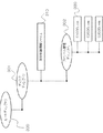
図1は、映像記録再生装置100のシステム構成図である。
<Configuration of video recording / reproducing
FIG. 1 is a system configuration diagram of the video recording / reproducing
映像記録再生装置100は、システム制御部101、記録再生ドライブ部102、チューナー部104、ストリーム制御部110、映像音声デコーダ部111および映像音声エンコーダ部116を備えている。
The video recording / reproducing
映像記録再生装置100は、デジタルインターフェース部112、メモリ部120または輝度情報調整部150を備えることができる。また、システム制御部101は、表示機器情報取得部151または放送番組解析制御部152を備えている。デジタルインターフェース部112は、表示装置通信部114を備えている。
The video recording /
システム制御部101は、映像記録再生装置100全体を統合制御している。
The
記録再生ドライブ部102は、光ディスク103に記録されている情報の読み出しを行う。また、記録再生ドライブ部102は、映像信号または音声信号などを光ディスク103等に書き込む。
The recording / reproducing
つまり、記録再生ドライブ部102は、読み取り部の一例である。また、記録再生ドライブ部102は、記録部の一例である。記録部102は、拡張ビデオのコンテンツと識別情報520とを標準ビデオに対応した記録媒体に記録する
That is, the recording /
なお、本実施の形態1では、一例として、記録再生ドライブ部102を光ディスクドライブ装置として説明を進める。しかし、記録再生ドライブ部102は、ハードディスクドライブ装置またはSDメディアドライブ装置などでもよい。その場合には、ハードディスク上またはSDメディア上に、ストリーム情報と再生制御情報とが記録されている。そして、記録再生ドライブ部102を通じて、情報の読み出しが行なわれる。
In the first embodiment, as an example, the description will proceed with the recording / reproducing
光ディスク103は、ストリーム情報DS1およびこのストリーム情報DS1の再生制御情報DCを記録している。
ストリーム情報DS1は、後述するように、符号化された映像信号が多重化された情報である。 The stream information DS1 , as described later, is information in which encoded video signals are multiplexed.
再生制御情報DCは、映像の属性情報、音声の属性情報を含んでいる。また、再生制御情報DCは、再生開始の時間情報と再生開始の位置情報との対応関係を示す情報を含んでいる。 Reproduction control information D C includes attribute information of the video, the attribute information of the speech. The reproduction control information D C includes information indicating a correspondence relationship between the position information of the reproduction start time information of the playback start.
映像の属性情報は、光ディスク103に記録されているストリーム情報DS1から分離された符号化された映像ストリームに関する情報である。また、音声の属性情報は、光ディスク103に記録されているストリーム情報DS1から分離した符号化された音声ストリームに関する情報である。再生開始の時間情報と再生開始の位置情報との対応関係を示す情報は、ストリーム情報DS1のアクセス単位(通常GOP単位)での対応関係を示す情報である。
The video attribute information is information relating to an encoded video stream separated from the stream information DS1 recorded on the
チューナー部104は、放送信号DBを受信する。また、チューナー部104は、受信した放送信号DBの復号化を行う。チューナー部104で復号化された放送信号DB1は、ストリーム制御部110を経由して、記録再生ドライブ102に送られる。記録再生ドライブ102は、復号化された放送信号DB1を、光ディスク103等に書き込む。なおDB1は、MPEG−2トランスポートストリームまたはMMT方式で多重化されたストリームである。
Tuner unit 104 receives broadcast signal D B. Further, the tuner unit 104 performs decoding of the broadcast signal D B received. The broadcast signal DB1 decoded by the tuner unit 104 is sent to the recording /
ストリーム制御部110は、システム全体のストリームの流れを統括制御している。
The
映像音声デコーダ部111は、ストリーム情報を逐次取り込んだ後に、符号化圧縮された映像ストリームまたは音声ストリームに分離する。その後、映像音声デコーダ部111は、MPEG−2などで符号化された映像ストリームをデコード処理して映像信号に復号する。一方、AC−3などで符号化された音声ストリームも、映像音声デコーダ部111は、同様に、デコード処理を行い出力音声信号に復号する。
The video /
映像音声エンコーダ部116は、映像信号と音声信号とを符号化圧縮し、MPEG−2トランスポートストリームまたはMMT方式で、再符号化する。 The video / audio encoder unit 116 encodes and compresses the video signal and the audio signal, and re-encodes them by using the MPEG-2 transport stream or the MMT method.
<録画処理の流れ>
次に、本実施の形態1における基本的な録画処理の流れについて説明する。
<Flow of recording process>
Next, a flow of a basic recording process according to the first embodiment will be described.
チューナー部104は、放送波の放送信号DBを受信する。チューナー部104は、MPEG−2トランスポートストリームまたはMMT方式で、受信した放送信号DBの復号化を行う。復号化された放送信号DBは、ストリーム制御部110を経由して、記録再生ドライブ102に送られる。復号化された放送信号DBは、記録再生ドライブ102で、例えば、光ディスク103に書き込まれる。
Tuner unit 104 receives broadcast signals D B of the broadcast waves. Tuner unit 104 is a MPEG-2 transport stream or MMT system, decrypts the broadcast signal D B received. Decoded broadcast signal D B, via the
ストリーム制御部110は、放送番組のフォーマットを解析する。そして、ストリーム制御部110は、放送番組の映像の属性情報または音声の属性情報を取得する。また、ストリーム制御部110は、後述するアクセスポイント情報を取得する。
The
これらの情報は、光ディスク103を再生する際の制御情報として使用される。そして、これらの情報は、光ディスク103に書き込まれる。これらの情報は、映像の属性情報、音声の属性情報またはアクセスポイント情報である。
These pieces of information are used as control information when reproducing the
なお、ストリーム情報DS1は、ダイレクト録画方式と、リエンコード録画方式とがある。ダイレクト録画方式は、放送信号DBをそのまま記録する方式である。リエンコード録画方式は、映像記録再生装置100内で再エンコードして記録する方式である。
The stream information DS1 includes a direct recording method and a re-encoding recording method. Direct recording method is a method of directly recording a broadcast signal D B. The re-encoding recording method is a method of re-encoding and recording in the video recording / reproducing
リエンコード録画方式の場合には、受信した放送信号DBは、ストリーム制御部110から映像音声デコーダ部111に送られる。ストリーム制御部110は、映像音声デコーダ部111に、信号DS2を送る。
In the case of re-encoding recording method, a broadcast signal D B received is sent from the
映像音声デコーダ部111は、符号化圧縮されたストリーム情報DS2を復号する。
The video /
復号化された放送信号(信号DV1,DA1)は、映像音声エンコーダ部116に送られる。復号化された放送信号(信号DV1,DA1)は、映像音声エンコーダ部116で符号化(リエンコード)される。 The decoded broadcast signals (signals D V1 and D A1 ) are sent to the video / audio encoder 116. The decoded broadcast signals (signals D V1 and D A1 ) are encoded (re-encoded) by the video / audio encoder 116.
そして、符号化(リエンコード)された放送信号(信号DS3)は、ストリーム制御部110を介して、記録再生ドライブ部102に送られる。記録再生ドライブ部102は、光ディスク103に符号化(リエンコード)された放送信号(信号DS3)を書き込む。
The encoded (re-encoded) broadcast signal (signal D S3 ) is sent to the recording /
リエンコード方式は、映像記録再生装置100側で記録ビットレートを自由に変更できるというメリットがある。一方、映像記録再生装置100のハードウェア資源を利用するため、録画時にシステムの同時動作が制約されるという短所がある。また、CPU負荷が大きくなるという短所がある。
The re-encoding method has an advantage that the recording bit rate can be freely changed on the video recording / reproducing
一方、ダイレクト録画方式は、ストリーム情報DS1をそのまま記録する。このため、映像記録再生装置100のハードウェア資源をあまり必要としないという長所がある。また、CPU負荷が少ないという長所がある。
On the other hand, in the direct recording method, the stream information DS1 is recorded as it is. For this reason, there is an advantage that the hardware resources of the video recording / reproducing
<再生処理の流れ>
次に、本実施の形態1における基本的な再生処理の流れについて説明する。
<Flow of playback process>
Next, a flow of a basic reproduction process according to the first embodiment will be described.
光ディスク103に記録されたストリーム情報DS1を再生する場合には、システム制御部101は、再生対象のストリーム情報DS1に関連する再生制御情報DCを、あらかじめ読み出す。光ディスク103に記録されたストリーム情報DS1は、符号化圧縮されている。符号化圧縮の方法は、例えば、MPEG−2 TS(MPEG−2 TransportStream)などの方法である。
When reproducing the stream information D S1 recorded on the
つまり、光ディスク103に記録されたMPEG−2 TS(MPEG−2 TransportStream)などの方法で符号化圧縮されたストリーム情報DS1を再生させる場合には、システム制御部101は、再生対象のストリーム情報DS1に関連する再生制御情報DCを、あらかじめ読み出しておく。
That is, when the stream information DS1 encoded and compressed by a method such as MPEG-2 TS (MPEG-2 Transport Stream) recorded on the
システム制御部101は、読み出した再生制御情報DCをメモリ部120に保持する。これによって、システム制御部101は、再生制御情報DCを、速やかに読み出すことができる。
The
システム制御部101は、再生制御情報DCを読み出す。そして、システム制御部101は、周辺デバイスに対して再生準備を行うように指示する。
The
その後、システム制御部101は、光ディスク103に記録されたストリーム情報DS1を読み出す。システム制御部101は、光ディスク103から読み出したストリーム情報DS1を、ストリーム制御部110に送る。ストリーム制御部110に送られたストリーム情報DS1は、映像音声デコーダ部111に供給される。
After that, the
つまり、光ディスク103から読み出したストリーム情報DS1は、ストリーム制御部110を経由して、映像音声デコーダ部111に供給される。ストリーム制御部110は、システム全体のストリームの流れを統括制御している。
That is, the stream information DS1 read from the
映像音声デコーダ部111は、ストリーム制御部110からストリーム情報DS2を取り込む。映像音声デコーダ部111は、ストリーム制御部110からストリーム情報DS2を逐次取り込む。
Video and
その後、映像音声デコーダ部111は、符号化圧縮された映像ストリームを分離して取り出す。または、映像音声デコーダ部111は、符号化圧縮された音声ストリームを分離して取り出す。
Thereafter, the video and
その後、映像音声デコーダ部111は、符号化された映像ストリームをデコード処理して映像信号DV1に復号する。映像ストリームの符号化は、例えば、MPEG−2などで行われている。
After that, the video /
一方、映像音声デコーダ部111は、符号化された音声ストリームをデコード処理して音声信号DA1に復号する。音声ストリームの符号化は、例えば、AC−3などで行われている。
On the other hand, the video /
そして、復号された映像信号DV1と音声信号DA1とは、輝度情報調整部150に送られる。
Then, the decoded video signal DV1 and audio signal DA1 are sent to the luminance
SDRビデオに対応した表示装置にHDRビデオ信号を出力する際には、輝度情報調整部150は、HDR信号の高輝度部分を削除する。そして、輝度情報調整部150は、輝度変換処理を行う。輝度変換処理は、例えば、暗い部分の階調を細かく表現するなどの処理である。
When outputting an HDR video signal to a display device supporting SDR video, the luminance
輝度情報調整部150は、拡張ビデオのコンテンツを標準ビデオのコンテンツに輝度変換する変換部である。
The luminance
その後、輝度情報調整部150で処理された映像信号DV2は、デジタルインターフェース部112に送られる。音声情報においては、映像音声デコーダ部111から受け取った信号(音声信号DA1)が、そのまま、デジタルインターフェース部112に送られる。
After that, the video signal DV2 processed by the luminance
デジタルインターフェース部112は、供給された映像信号DV2および音声信号DA1を、HDMI(登録商標)インターフェースに適合した信号に変換する。デジタルインターフェース部112で変換された信号は、表示装置113に送られる。 The digital interface unit 112 converts the supplied video signal DV2 and audio signal DA1 into a signal compatible with the HDMI (registered trademark) interface. The signal converted by the digital interface unit 112 is sent to the display device 113.
表示装置113は、デジタルインターフェース部112から、映像信号DV3および音声信号DA2を受け取る。表示装置113によって、HDMI信号に変換された映像信号DV3およびHDMI信号に変換された音声信号DA2は視聴される。 Display device 113, the digital interface unit 112 receives a video signal D V3 and the audio signal D A2. By the display device 113, the video signal DV3 converted into the HDMI signal and the audio signal DA2 converted into the HDMI signal are viewed.
また、映像記録再生装置100は、映像信号DV3および音声信号DA2を表示装置113に出力する際に、映像信号DV3に関する映像属性情報を、表示装置113に伝送する。表示装置通信部114は、映像属性情報を、表示装置113に送る。表示装置通信部114は、デジタルインターフェース部112に備えられている。映像属性情報は、表示装置通信部114によって、表示装置113に伝送される。
When outputting the video signal DV3 and the audio signal DA2 to the display device 113, the video recording / reproducing
映像属性情報は、HDMI規格で規定されている。また、映像属性情報は、ブランキング期間に伝送される。この映像属性情報は、映像信号DV3がHDRビデオであるか否かの情報、最大出力輝度レベル情報またはマスタリング環境情報などを含んでいる。 Video attribute information is defined by the HDMI standard. The video attribute information is transmitted during a blanking period. The video attribute information includes information as to whether the video signal DV3 is an HDR video, maximum output luminance level information, mastering environment information, and the like.
また、表示機器情報取得部151は、表示装置通信部114を通じて、各種の情報を取得する。
In addition, the display device
表示機器情報取得部151の取得する情報は、表示装置113の表示可能なフォーマット情報DFを含んでいる。表示可能なフォーマット情報DFは、例えば、表示装置113がHDRに対応しているか否かの情報である。また、表示可能なフォーマット情報DFは、表示装置113の表示性能の情報を含んでいる。
The information acquired by the display device
また、表示機器情報取得部151の取得する情報は、表示装置113の最大出力輝度レベル、推奨最大輝度レベル、製造者名、製造年、表示可能解像度またはインターレース対応の可否などの情報を含んでいる。
The information acquired by the display device
つまり、表示機器情報取得部151は、接続する表示装置113が拡張ビデオを表示できるか否かの情報DFを取得する取得部の一例である。
That is, the display device
表示装置113は、表示可能なフォーマット情報DFをEDID(Extended Display Identification Data)として不揮発性メモリに記録している。 The display device 113 records the displayable format information DF as the EDID (Extended Display Identification Data) in the non-volatile memory.
なお、本実施の形態1では、HDMIを利用した例について説明を進める。しかし、表示装置通信部114は、表示装置113の表示可能なフォーマット情報DFを取得できればよい。そのため、表示装置通信部114は、iLinkまたは赤外線通信などの検出機構を用いて、表示装置113の表示可能なフォーマット情報DFを取得しても良い。
In the first embodiment, an example using HDMI will be described. However, the display
また、本実施の形態1では、表示装置通信部114は、デジタルインターフェース部112に備えられている。しかし、表示装置通信部114は、デジタルインターフェース部112以外の部分に配置されてもよい。
In the first embodiment, the display
なお、図1に示す記録再生ブロック115は、映像音声ストリームの記録再生機能の総称である。記録再生ブロック115は、システム制御部101から指示を受ける。そして、記録再生ブロック115は、システム制御部101からの指示を基に、記録再生ブロック115内の構成要素を制御する。記録再生ブロック115は、ストリーム情報の記録を行う。また、記録再生ブロック115は、ストリーム情報の再生を行う。
The recording / reproducing
記録再生ブロック115は、記録媒体103に記録されているコンテンツを再生する再生部の一例である。
The recording / reproducing
操作部130は、ユーザーなどが映像記録再生装置100に対して要求などを入力する装置である。例えば、操作部130は、映像記録再生装置100の操作パネルである。操作パネルは、映像記録再生装置100のフロントパネル等に配置されている。また、操作部130は、やリモコンなどでもよい。リモコンは、利用者が操作する遠隔操作機器のことである。
The
システム制御部101は、操作部130から受け取った要求または命令の内容を解釈する。そして、システム制御部101は、操作部130から受け取った要求などの内容に基づいて、記録再生ブロック115を制御する。そして、システム制御部101は、ストリーム情報を再生する。
The
放送番組解析制御部152は、映像記録再生装置100が記録する放送信号DBの輝度フォーマット情報と、輝度分布情報とを解析する。輝度フォーマット情報は、放送信号DBがHDRであるかSDRであるか等の情報である。そして、放送番組解析制御部152は、その解析結果を光ディスク103に記録する。
Broadcast program
放送番組解析制御部152は、拡張ビデオのコンテンツを標準ビデオのコンテンツに輝度変換する場合の変換情報を生成するコンテンツ情報生成部の一例である。変換情報は、例えは、後述する輝度分布[8]525などである。
The broadcast program
また、放送番組解析制御部152は、記録媒体103に記録されているコンテンツが拡張ビデオであるか否かの識別情報522を読み出す制御部の一例である。type_HDR_SDR522は、この識別情報の一例である。
The broadcast program
また、制御部152は、拡張ビデオのコンテンツを標準ビデオのコンテンツに輝度変換する場合の変換情報525を読み出す。輝度分布[8]525は、この変換情報の一例である。
Further, the
また、放送番組解析制御部152は、映像記録再生装置100が放送信号DBを再生する際に、光ディスク103に記録した輝度フォーマット情報および輝度分布情報を読み出す。そして、放送番組解析制御部152は、読み出した輝度フォーマット情報および輝度分布情報に基づいて輝度情報調整部150を制御する。
The broadcast program
なお、表示機器情報取得部151および放送番組解析制御部152は、システム制御部101の内部のファームウェアなどで構成される例を示している。しかし、表示機器情報取得部151または放送番組解析制御部152は、システム制御部101の外部に配置されても構わない。また、表示機器情報取得部151の機能または放送番組解析制御部152の機能は、ハードウェアで実現されても構わない。
Note that the display device
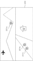
図2は、HDRビデオについての説明図である。 FIG. 2 is an explanatory diagram of HDR video.
図2は、表示装置113に表示されるHDRビデオ映像200の一例を示している。
FIG. 2 shows an example of an
HDRは、上述のように、ハイダイナミックレンジの略称である。そして、HDRビデオは、表示処理のできる輝度信号の最小値から最大値までの範囲が、従来のSDRビデオよりも広い。 HDR is an abbreviation for high dynamic range, as described above. HDR video has a wider range from the minimum value to the maximum value of the luminance signal that can be displayed than the conventional SDR video.
従来のSDRビデオでは、表示処理のできる輝度範囲が限定されている。例えば、SDRビデオが、太陽の煌めき又は川に映る光の反射などの高輝度の表現を行うことができなかった。 In the conventional SDR video, a luminance range in which display processing can be performed is limited. For example, SDR video has been unable to render high-brightness representations such as the glitter of the sun or the reflection of light reflected on rivers.
また、従来のSDRビデオでは、高輝度の部分での細かな階調表現ができなかった。そのため、白で飽和した「白とび」と呼ばれる現象が発生していた。例えば、SDRビデオでは、図2中の、太陽201aの煌めき又は太陽光が川に反射したときの煌めき部分201b,201c等の階調表現が損なわれていた。また、SDRビデオでは、高輝度の部分の表示自体も行うことができなかった。
Further, in the conventional SDR video, fine gradation expression cannot be performed in a high luminance portion. For this reason, a phenomenon called "white jump" saturated with white has occurred. For example, in the SDR video, the gradation expression of the glitter of the sun 201a or the
HDRビデオ規格では、HDRビデオが記録された記録媒体を、HDRビデオ対応の再生装置及び表示装置で視聴する。HDRビデオ対応の再生装置及び表示装置は、前述した高輝度部分の表示又は高輝度部分の階調表現が可能である。そして、より高品位な映像視聴を楽しむことが可能となる。 According to the HDR video standard, a recording medium on which an HDR video is recorded is viewed on a playback device and a display device compatible with the HDR video. The playback device and the display device compatible with the HDR video can display the above-described high-luminance portion or express the gradation of the high-luminance portion. Then, it is possible to enjoy higher quality video viewing.
図3は、光ディスク103の論理ファイル構造を示した図である。
FIG. 3 is a diagram showing a logical file structure of the
ルートディレクトリ300は、論理的に階層構造を成すファイル構造の最上位階層のディレクトリ構造である。ディスクディレクトリ301は、ルートディレクトリ300の下位階層に配置されるディレクトリ構造である。
The
ディスクディレクトリ301は、再生制御情報ファイル310及びストリーム管理ディレクトリ302を備えている。
The
再生制御情報ファイル310は、再生制御情報DCをファイル形式で記録している。再生制御情報DCは、光ディスク103に記録されているディスクコンテンツを管理する情報である。
Reproduction control information file 310 records the reproduction control information D C in a file format. Reproduction control information D C is information for managing disc content recorded on the
ストリーム管理ディレクトリ302は、ストリーム情報ファイル320をまとめて記録したフォルダである。ストリーム情報ファイル320は、ストリーム情報DS1の一例である。
The
図3では、ストリーム情報ファイル320は、5桁のファイル名で記録されているとして説明を進める。ファイル名は、5桁の数字であれば良く、連番である必要はない。 In FIG. 3, the description will proceed assuming that the stream information file 320 is recorded with a five-digit file name. The file name may be a five-digit number, and need not be a sequential number.
なお、ストリーム情報ファイル320を、個別のディレクトリ内に配置する例を示している。しかし、ストリーム情報ファイル320を、ルートディレクトリ300に直接配置しても良い。また、ストリーム情報ファイル320を、他のディレクトリ位置に配置しても構わない。
Note that an example is shown in which the stream information file 320 is arranged in an individual directory. However, the stream information file 320 may be directly arranged in the
また、ストリーム情報ファイル320を、ある管理単位毎に個別のファイルとして形成している例を示している。しかし、ストリーム情報ファイル320を、1つのファイルにまとめて記録しても構わない。 Also, an example is shown in which the stream information file 320 is formed as an individual file for each certain management unit. However, the stream information file 320 may be collectively recorded in one file.
図4は、ストリーム情報ファイル320の内部データ構造を示した説明図である。
FIG. 4 is an explanatory diagram showing the internal data structure of the
ストリーム情報ファイル320は、複数のパケット400を備えている。パケット400は、固定長のデータ単位で構成されている。パケット層405には、複数のパケット400が含まれている。
The stream information file 320 includes a plurality of
映像データ、音声データ又はストリーム管理データ等は、パケット400の単位に分割されている。そして、これらのデータは多重化される。ストリーム情報ファイル320は、これらの多重化されたデータを含む。
Video data, audio data, stream management data, and the like are divided into
ストリーム情報ファイル320は、ストリーム情報DS1に相当する。また、ストリーム管理データは、ストリーム情報ファイル320の属性情報である。ストリーム管理データには、例えば、映像のコーデック、解像度、フレームレートまたはアクセスポイント情報などが記録されている。映像データ、音声データ又はストリーム管理データ等は、ストリーム情報DS1に含まれている。
The stream information file 320 corresponds to the stream information DS1 . The stream management data is attribute information of the
パケット400は、ヘッダ情報401及びデータ領域403を備えている。
The
それぞれのパケット400の先頭には、ヘッダ情報401がある。ヘッダ情報401に記述されたID402(Identification)によって、パケット400内のデータを識別する。
At the head of each
ストリーム制御部110は、このID402を識別して、ストリーム情報ファイル320を、映像データ、音声データ又はストリーム管理データ等に分離する。
The
図5は、再生制御情報ファイル310のシンタックスの説明図である。
FIG. 5 is an explanatory diagram of the syntax of the playback
光ディスク103内に記録されている番組タイトルをプレイリストと呼ぶ。プレイリストには、「num_of_playlist501」が記録されている。「num_of_playlist501」は、プレイリストの総数を示す。次のループ文(for以下)は、「num_of_playlist501」の数だけ繰り返される。
The program title recorded on the
なお、プレイリストは、後述する1つ以上のプレイアイテムから構成される。また、1つのプレイアイテムは、1枚以上の映像フレームから構成されている。1枚の映像フレームは、複数のピクセルから構成されている。 Note that the playlist is composed of one or more play items described later. One play item is composed of one or more video frames. One video frame is composed of a plurality of pixels.
プレイリストは、複数のプレイアイテムから構成される。プレイリストには、「num_of_playitem502」が記録されている。「num_of_playitem502」は、プレイアイテムの総数を示す。次のループ文(for以下)は、「num_of_playitem502」の数だけ繰り返される。
The playlist is composed of a plurality of play items. “
プレイアイテムは、1つの再生区間の情報が記録されている。再生区間の情報は、再生対象のストリームファイル名503、再生開始時間504または再生終了時間505を含んでいる。再生区間の情報に基づいて、映像記録再生装置100は、ストリーム情報ファイル320のどの区間を再生すればよいのかを判断することができる。
In the play item, information of one playback section is recorded. The information of the playback section includes a stream file name 503 to be played, a playback start time 504, or a playback end time 505. Based on the information of the playback section, the video recording /
また、再生制御情報ファイル310中には、「num_of_stream510」が記録されている。「num_of_stream510」は、光ディスク103に記録されているストリーム情報ファイル320の総数を示す。次のループ文(for以下)は、「num_of_stream510」の数だけ繰り返される。
In the reproduction
ストリーム情報ファイル名511は、ストリーム情報ファイル320の名前を示す5桁の数字情報である。
The stream
ソース属性情報520は、放送番組の輝度フォーマット情報または輝度分布情報などをまとめたものである。ソース属性情報520は、「is_source_info521」、「type_HDR_SDR522」、「Max_LL523」、「Max_Ave_LL524」、「輝度分布[8]525」または「is_transcode526」を含んでいる。つまり、ソース属性情報520は、コンテンツが拡張ビデオであるか否かの識別情報である。
The source attribute information 520 is a collection of luminance format information or luminance distribution information of a broadcast program. The source attribute information 520 includes “
「is_source_info521」は、放送番組を記録した際に、フォーマット情報または輝度分布情報を正常に記録されているか否かを示すフラグである。
“
このフラグの値が「1」の場合には、「type_HDR_SDR522」、「Max_LL523」、「Max_Ave_LL524」、「輝度分布[8]525」または「is_transcode526」のフィールドが有効であることを示す。
When the value of this flag is “1”, it indicates that the fields of “type_HDR_SDR522”, “Max_LL523”, “Max_Ave_LL524”, “luminance distribution [8] 525”, or “
一方、このフラグの値が「0」の場合には、フィールドが無効であることを示す。 On the other hand, when the value of this flag is “0”, it indicates that the field is invalid.
「type_HDR_SDR522」は、プレイリストがHDRビデオであるかSDRビデオであるかを識別するための情報である。なお、複数のHDR技術を用いる場合には、「type_HDR_SDR522」にHDRの種別を示す情報を記録して、管理してもよい。 “Type_HDR_SDR522” is information for identifying whether a playlist is an HDR video or an SDR video. When a plurality of HDR technologies are used, information indicating the type of HDR may be recorded in “type_HDR_SDR522” and managed.
なお、本実施の形態1では、HDRとして、後述するHDR_HLG方式を用いるものとして説明を進める。 In the first embodiment, the description will be given on the assumption that the HDR_HLG method described later is used as the HDR.
「Max_LL523」は、プレイリスト中のピクセルの最大の出力輝度レベルを示す。「Max_Ave_LL524」は、プレイリストを構成する映像フレーム毎の平均輝度を算出する。そして、「Max_Ave_LL524」は、最大の平均輝度を持った映像フレームの出力輝度レベルを示す。 “Max_LL523” indicates the maximum output luminance level of the pixel in the playlist. “Max_Ave_LL524” calculates an average luminance for each video frame forming a playlist. “Max_Ave_LL524” indicates the output luminance level of the video frame having the maximum average luminance.
「輝度分布[8]525」は、輝度の分布状況を示すための配列情報である。例えば、放送番組の映像フレーム中で、ピクセル毎の輝度統計処理を行う。そして、「輝度分布[8]525」は、輝度のヒストグラム情報を示す。 “Luminance distribution [8] 525” is array information for indicating a luminance distribution state. For example, in a video frame of a broadcast program, luminance statistical processing is performed for each pixel. "Luminance distribution [8] 525" indicates luminance histogram information.
本実施の形態1では、「輝度分布[8]525」は、配列として8段階に区分けして分布状況を示している。「輝度分布[8]525」の[8]が8段階の配列を示している。ヒストグラムの具体例は、図8を用いて説明する。 In the first embodiment, “brightness distribution [8] 525” indicates a distribution state divided into eight stages as an array. [8] of “luminance distribution [8] 525” indicates an eight-stage arrangement. A specific example of the histogram will be described with reference to FIG.
なお、今回は8段階に区分けして説明を行っている。しかし、配列を更に細分化してもよい。また、配列を更に粗く区分けしてもよい。 This time, the explanation is divided into eight stages. However, the sequence may be further subdivided. Further, the array may be further roughly divided.
また、ピクセル毎の輝度の統計結果から、全体の大部分を含む輝度設定値を保持してもよい。「大部分」とは、例えば、95%である。 Alternatively, a luminance set value including most of the whole may be held from the statistical result of the luminance for each pixel. "Most" is, for example, 95%.
「is_transcode526」は、放送番組を録画する際に、リエンコード録画方式で録画されているか否かを示す。リエンコード録画は、放送信号をデコードして、装置の備えるエンコーダで再符号化する方式である。このため、HDR放送であってもSDR信号として記録される。
“
属性情報管理テーブル530には、属性情報が記録されている。記録されている属性情報は、ストリーム情報ファイル320の中で使用される映像情報または音声情報などの属性情報である。
Attribute information is recorded in the attribute information management table 530. The recorded attribute information is attribute information such as video information or audio information used in the
また、属性情報管理テーブル530には、ID402などが格納されている。ID402は、ストリームを構成している映像情報または音声情報毎にパケットを識別する情報(パケットID)である。このパケットIDを用いて、ストリーム制御部110は、映像データ、音声データまたはストリーム管理データ等を分離する。
The attribute information management table 530 stores the
また、アクセスポイント管理テーブル540は、アクセスポイント毎のストリームの読み出し位置とアクセスポイント毎の再生開始時間とを記録したリスト情報である。このリスト情報を用いて、ランダムアクセス再生が行われる。ランダムアクセス再生は、例えば、タイムサーチまたは特殊再生などである。 The access point management table 540 is list information that records a stream read position for each access point and a reproduction start time for each access point. Random access reproduction is performed using this list information. The random access reproduction is, for example, time search or special reproduction.
なお、例えば、映像データがMPEG−2ビデオストリームでエンコードされている場合には、GOP(Group of Picture)の先頭がアクセスポイントに相当する。GOP毎に、再生開始時間の情報と再生開始アドレスの情報とが記述されている。再生開始アドレスは、ストリームファイルの先頭を起算とした位置である。 For example, when the video data is encoded by the MPEG-2 video stream, the head of a GOP (Group of Picture) corresponds to the access point. The information of the reproduction start time and the information of the reproduction start address are described for each GOP. The reproduction start address is a position starting from the head of the stream file.
映像記録再生装置100は、再生開始時間の情報を基にして、ストリーム情報ファイル320の再生開始アドレスを割り出す。そして、映像記録再生装置100は、ランダムアクセス再生を行う。
The video recording / reproducing
図6は、映像ストリームのデータ構造を示す説明図である。図6は、映像ストリーム600のデータ構造を示している。映像ストリーム600は、ストリーム情報DS2の一例である。
FIG. 6 is an explanatory diagram showing a data structure of a video stream. FIG. 6 shows the data structure of the
映像ストリーム600は、ストリーム情報ファイル320を、ストリーム制御部110でデマルチプレクスされることによって抽出されて符号化圧縮されている。映像ストリーム600は、符号化圧縮単位となるGOP(Group Of Picture)601単位で情報圧縮されている。
The
GOP601は、Iピクチャ610、Pピクチャ611又はBピクチャ612を含んでいる。
The
Iピクチャ610は、フレーム内でデータ圧縮されている。Pピクチャ611は、時間的に前方向のIピクチャによる動き補償を加えてデータ圧縮されている。Bピクチャ612は、時間的に前後方向のIピクチャ610又はPピクチャ611による動き補償を加えてデータ圧縮されている。
The I picture 610 is data compressed in the frame. The
例えば、この符号化圧縮は、0.5秒の再生時間ごとに行われている。 For example, this encoding compression is performed every 0.5 second reproduction time.
Iピクチャ610は、GOP601の先頭に位置している。Iピクチャ610は、GOP601の中で最初にデコードされる。また、Iピクチャ610は、表示時刻情報620、映像属性情報630又は符号化映像データ640を含んでいる。
The I picture 610 is located at the head of the
表示時刻情報620には、PTS(Presentation Time Stamp)が付与されている。また、表示時刻情報620には、表示装置113に提示する時間情報が記録される。
The
なお、表示時刻情報620は、映像と音声とが同期できる時刻情報であればよい。表示時刻情報620に、PTSではなく、NTP(Network Time Protocol)で定義される時刻情報などを利用しても構わない。
Note that the
映像属性情報630は、AUD631、SPS632、PPS633又はSEI634を含んでいる。
AUD631は、アクセス・ユニット・デリミター(Access−Unit−Delimiter)の略語である。AUD631は、映像のアクセスユニットの先頭を示す識別子情報を示している。また、AUD631は、映像のアクセスユニットに含まれるスライスの種類を示す情報を含んでいる。
The
また、SPS632は、システム・パラメータ・セット(System−Parameter−Set)の略語である。SPS632には、GOP601全体の符号化に関わるプロファイル、レベル、解像度、フレームレート又はビットレート上限値などの情報が記載される。
The
PPS633は、ピクチャー・パラメータ・セット(Picture−Parameter−Set)の略語である。PPS633は、ピクチャ全体の符号化に関わる情報を持っている。また、PPS633には、エントロピー符号化モード又はピクチャ単位の量子化パラメータ等の情報が記録される。
SEI634は、サプリメンタル・エレメント・インフォメーション(Supplimental−Element−Infomation)の略語である。SEI634には、GOP601のメタデータ情報が記録される。
SEI 634 is an abbreviation for Supplemental-Element-Information. In the SEI 634, metadata information of the
本実施の形態1では、再生制御情報ファイル310にソース属性情報520を記録しているものとして説明を進めている。しかし、ストリーム情報ファイル320の中のSEI634にソース属性情報520を保持しても良い。
In the first embodiment, description is given on the assumption that the source attribute information 520 is recorded in the reproduction
なお、Iピクチャ610以外のPピクチャ611及びBピクチャ612は、図6で示すように、SPS632及びSEI634を含まない。
The
図7は、輝度設定値701と出力輝度の相対レベル702との相関関係の説明図である。輝度設定値701は、SDRとHDRとに関する設定値である。
FIG. 7 is an explanatory diagram of the correlation between the
図7の縦軸は、輝度設定値701を示す。図7の横軸は、出力輝度相対レベル702を示す。また、図7中に、トーンカーブ(SDR)710とトーンカーブ(HDR_HLG)720とを示す。トーンカーブ710(SDR)は、SDRビデオに用いられる。トーンカーブ(HDR_HLG)720は、HDRビデオに用いられる。
The vertical axis of FIG. 7 indicates the
トーンカーブ(HDR_HLG)720は、ハイブリッドログガンマ(Hybrid Log Gamma)方式を採用している。 The tone curve (HDR_HLG) 720 employs a hybrid log gamma (Hybrid Log Gamma) method.
ハイブリッドログガンマ方式は、暗い部分には従来のガンマカーブを採用し、明るい部分には対数カーブを採用している。つまり、ハイブリッドログガンマ方式は、ハイブリッド方式である。 The hybrid log gamma method employs a conventional gamma curve for dark parts and a logarithmic curve for bright parts. That is, the hybrid log gamma method is a hybrid method.
また、ハイブリッドログガンマ方式は、相対輝度方式を採用している。相対輝度方式は、従来のSDR方式も採用している。相対輝度方式は、基準白の相対値による変換式を使用する。これによって、ハイブリッドログガンマ方式は、従来テレビとの互換性が比較的に高い。 The hybrid log gamma system employs a relative luminance system. The relative luminance method also employs the conventional SDR method. The relative luminance method uses a conversion formula based on the relative value of the reference white. Thus, the hybrid log gamma method has relatively high compatibility with the conventional television.
輝度設定値701は、符号化された映像信号をデコードした際の、映像フレームを構成する各ピクセルの輝度値を示す。本実施の形態1では、映像信号の輝度設定値701は、例えば、10ビットで表現されている。このため、輝度設定値701は、1024諧調(2の10乗)の分解能を持つ。なお、輝度設定値701は、8ビットの分解能または12ビットの分解能を持ってもよい。
The
通常、SDRビデオでは、100[nit]程度の明るさが、最高輝度としてマスタリングされている。輝度設定値701は、相対輝度方式と呼ばれる輝度表現方法を持つ。
Normally, in SDR video, brightness of about 100 [nit] is mastered as the highest brightness. The
SDRビデオを再生する際に表現できる最大の輝度(最大表現可能輝度)を「基準白」と呼ぶ。図7では、「基準白」は、トーンカーブ(SDR)710の輝度設定値701の値が1024の場合の出力輝度相対レベル702の値である。
The maximum luminance that can be expressed when reproducing the SDR video (maximum expressible luminance) is called “reference white”. In FIG. 7, “reference white” is the value of the output luminance
HDR_HLG方式では、基準白の約12倍の明るさの表現が可能である。トーンカーブ(SDR)710の出力輝度相対レベル702の最大値は「1」である。トーンカーブ(HDR_HLG)720の出力輝度相対レベル702の最大値は「12」である。
In the HDR_HLG system, it is possible to represent about 12 times the brightness of the reference white. The maximum value of the output luminance
なお、出力輝度相対レベル702の「0」は、例えば、黒を示す。また、出力輝度相対レベル702の「1」は、例えば、基準白の輝度値を示す。また、出力輝度相対レベル702の「12」は、例えば、白のピークの輝度値を示す。その後、図7において、出力輝度相対レベル702の数値が大きいほど高輝度であることを示す。
Note that “0” of the output luminance
トーンカーブ(SDR)710は、輝度設定値701の全範囲がガンマカーブで設定されている。
In the tone curve (SDR) 710, the entire range of the
一方、トーンマップ(HDR_HLG)720は、輝度設定値701の前半分がガンマカーブで設定されている。そして、トーンマップ(HDR_HLG)720は、輝度設定値701の後半分が対数カーブで設定されている。そのため、後半分を示す明るい部分は、カーブの傾きが急峻となる。トーンカーブ(SDR)710と比較して、トーンマップ(HDR_HLG)720は、最高輝度(出力輝度相対レベル702)を高く設定できる。つまり、トーンマップ(HDR_HLG)720は、出力輝度相対レベル702の最大値を高く設定できる。
On the other hand, in the tone map (HDR_HLG) 720, the first half of the
図7では、輝度設定値701の前半分は、輝度設定値701の値が0から512までの範囲である。また、輝度設定値701の後半分は、輝度設定値701の値が512から1024までの範囲である。
In FIG. 7, the first half of the
なお、ここで「急峻」とは、輝度設定値701の変化量に対する、出力輝度相対レベルの変化量が大きいことをいう。このため、図7では、グラフの傾きが緩やかな方が「急峻」となる。
Here, “steep” means that the change amount of the output luminance relative level with respect to the change amount of the
このように、HDR_HLGビデオは、SDRビデオと比較すると出力輝度相対レベル702のダイナミックレンジを広く設定できる。このため、映像記録再生装置100は、一般的なSDRビデオでは表示できなかった高い輝度の表現を行うことができる。映像記録再生装置100は、例えば、太陽の輝きなどを表現できる。そして、映像記録再生装置100は、高品位な映像表示ができる。
Thus, the HDR_HLG video can set a wider dynamic range of the output luminance
一方、コンテンツによっては、明るい部分で表現できる階調が粗くなるといったデメリットもある。つまり、映像全体の表現可能な階調は、少なくなる。そして、画質が悪くなるという問題がある。 On the other hand, depending on the content, there is a demerit that the gradation that can be expressed in a bright portion becomes coarse. That is, the number of gradations that can be expressed in the entire video is reduced. And there is a problem that image quality deteriorates.
また、最も高い輝度設定値701に近い輝度値を持ったピクセルの出現頻度は低い。例えば、輝度設定値701が「1023」のピクセルの出現頻度は低い。つまり、通常の映像では、輝度設定値701が「1023」のピクセルは、頻繁に現れない。
Also, the frequency of appearance of a pixel having a luminance value close to the highest
また、HDR_HLGビデオ信号を、SDR対応の表示装置113で、そのまま表示させる場合には、ある一定の互換性は、担保される。しかし、HDR_HLGビデオ信号とSDRビデオ信号とでは、トーンカーブ自体が異なっている。また、コンテンツ自体はHDR_HLGでマスタリングされているため、再生した際の表示品質は悪くなる。 Further, when the HDR_HLG video signal is displayed as it is on the SDR-compatible display device 113, certain compatibility is ensured. However, the tone curve itself is different between the HDR_HLG video signal and the SDR video signal. Also, since the content itself is mastered by HDR_HLG, the display quality at the time of reproduction is deteriorated.
図8は、輝度ヒストグラム情報に関する説明図である。図8(A)は、HDR_HLG方式の輝度分布の一例を示している。図8(B)は、SDR方式の輝度分布の一例を示している。縦軸は、各ピクセルの出現度数801を示す。横軸は、輝度設定値701を示す。
FIG. 8 is an explanatory diagram regarding the luminance histogram information. FIG. 8A shows an example of a luminance distribution of the HDR_HLG method. FIG. 8B shows an example of the luminance distribution of the SDR method. The vertical axis indicates the
本実施の形態1で説明する輝度ヒストグラム情報の階級は、輝度設定値701を8分割している。また、本実施の形態1では、輝度を10ビット(=1024段階)で表現している。このため、例えば、輝度階級802[0]は、輝度設定値701が0〜127までの暗い部分を示す。また、輝度階級802[7]は、輝度設定値701が896〜1023までの明るい部分を示す。
The class of the luminance histogram information described in the first embodiment divides the
図8(A)は、HDR_HLGの放送信号を記録した際のヒストグラムである。図7で示したトーンカーブ(HDR_HLG)720は、高輝度部分の傾きが急俊である。このため、図8(A)の輝度分布(HDR_HLG)810では、高輝度部分の出現度数801は少ない。例えば、輝度階級802[6]および輝度階級802[7]の出現度数801は少ない。
FIG. 8A is a histogram when an HDR_HLG broadcast signal is recorded. In the tone curve (HDR_HLG) 720 shown in FIG. 7, the inclination of the high luminance portion is steep. Therefore, in the luminance distribution (HDR_HLG) 810 in FIG. 8A, the frequency of
図8(B)は、SDRの放送信号を記録した際のヒストグラムである。図7で示したトーンカーブ(SDR)710は、均一なガンマカーブである。このため、図8(B)の輝度分布(SDR)820では、輝度設定値701において、偏った出現度数になる可能性は低い。
FIG. 8B is a histogram when an SDR broadcast signal is recorded. The tone curve (SDR) 710 shown in FIG. 7 is a uniform gamma curve. For this reason, in the luminance distribution (SDR) 820 of FIG. 8B, the
輝度分布(HDR_HLG)810の番組がSDR対応の表示装置113に表示されると、番組はコンテンツ制作者の意図よりも暗いシーンとして表示される。 When the program of the luminance distribution (HDR_HLG) 810 is displayed on the SDR-compatible display device 113, the program is displayed as a scene darker than the content creator's intention.
図9は、コンテンツ及び表示装置に関して、HDRビデオとSDRビデオとを組合せた場合のシステムの挙動についての説明図である。 FIG. 9 is an explanatory diagram of the behavior of the system when HDR video and SDR video are combined with respect to the content and the display device.
コンテンツと表示装置とに関するHDR対応の有無の組合せとしては、組合せ(SDR_SDR)901、組合せ(SDR_HDR)902、組合せ(HDR_SDR)903又は組合せ(HDR_HDR)904の4パターンが存在する。 As the combination of the presence and absence of HDR support for the content and the display device, there are four patterns of a combination (SDR_SDR) 901, a combination (SDR_HDR) 902, a combination (HDR_SDR) 903, or a combination (HDR_HDR) 904.
組合せ(SDR_SDR)901では、コンテンツと表示装置113との両方が、従来のSDRビデオに対応した場合の組合せ例である。 The combination (SDR_SDR) 901 is an example of a combination in which both the content and the display device 113 correspond to the conventional SDR video.
組合せ(SDR_SDR)901では、映像音声デコーダ部111で復号された映像信号DV1は、輝度情報調整部150で輝度調整が行われない。復号された映像信号DV1は、そのまま、デジタルインターフェース部112を介して、SDRビデオ信号として表示装置113に伝送される。表示装置113は、この映像信号DV1を、そのままSDRビデオとして表示する。
In combination (SDR_SDR) 901, a video signal D V1 decoded by the video and
組合せ(SDR_HDR)902では、コンテンツがSDRビデオである。また、表示装置113は、HDRビデオ対応の機器である。 In the combination (SDR_HDR) 902, the content is an SDR video. The display device 113 is a device that supports HDR video.
組合せ(SDR_HDR)902では、映像音声デコーダ部111で復号された映像信号DV1は、輝度情報調整部150で輝度調整が行われない。復号された映像信号DV1は、そのまま、デジタルインターフェース部112を介して、SDRビデオ信号として表示装置113に伝送される。表示装置113側では、SDRビデオ信号をそのままSDRビデオとして表示する。
In combination (SDR_HDR) 902, a video signal D V1 decoded by the video and
組合せ(HDR_SDR)903では、コンテンツがHDRビデオである。また、表示装置113は、SDRビデオ対応の機器である。 In the combination (HDR_SDR) 903, the content is an HDR video. The display device 113 is an SDR video-compatible device.
組合せ(HDR_SDR)903では、映像音声デコーダ部111で復号された映像信号DV1に対して、図5に示すソース属性情報520から輝度分布[8]525を読み出す。そして、SDRビデオでは表現できない範囲であって、全体のピクセル数の95%が属する階級を表現できる輝度設定値の範囲を算出する。
In combination (HDR_SDR) 903, the video signal D V1 decoded by the video and
そして、算出された輝度設定値以外の領域部分を削除する。その削除された部分が暗い部分の階調を表現できるように、輝度情報調整部150は輝度変換を行う。
Then, the area portion other than the calculated luminance setting value is deleted. The luminance
なお、ここでは、設定値を95%とした。しかし、90%でも構わないし、99%でも構わない。その後、輝度変換されたビデオ信号は、デジタルインターフェース部112を通じて、SDRビデオ信号として表示装置113に伝送される。表示装置113は、この輝度変換されたビデオ信号を、そのままSDRビデオとして表示する。 Here, the set value was 95%. However, it may be 90% or 99%. Thereafter, the luminance-converted video signal is transmitted to the display device 113 via the digital interface unit 112 as an SDR video signal. The display device 113 displays the luminance-converted video signal as it is as an SDR video.
上記の例では、輝度分布[8]525を用いて輝度変換を行った。しかし、ソース属性情報520に輝度変換時に利用可能な情報を入れておいて、再生時にその輝度変換情報を用いて輝度変換を行うことも可能である。輝度変換時に利用可能な情報は、例えば、輝度変換式などである。 In the above example, the luminance conversion was performed using the luminance distribution [8] 525. However, it is also possible to put information that can be used at the time of luminance conversion in the source attribute information 520 and perform luminance conversion at the time of reproduction using the luminance conversion information. Information that can be used at the time of luminance conversion is, for example, a luminance conversion formula.
組合せ(HDR_HDR)904では、コンテンツと表示装置113との両方が、HDRビデオに対応した場合の組合せ例である。 The combination (HDR_HDR) 904 is an example of a combination in which both the content and the display device 113 support HDR video.
組合せ(HDR_HDR)904では、通常再生を行う場合には、映像音声デコーダ部111で復号された映像信号DV1は、輝度情報調整部150で輝度調整が行われない。復号された映像信号DV1は、そのまま、デジタルインターフェース部112を介して、HDRビデオ信号として表示装置113に伝送される。表示装置113は、この映像信号DV1を、そのままHDRビデオとして表示する。
In combination (HDR_HDR) 904, in the case of performing normal reproduction, the video signal D V1 decoded by the video and
なお、今回、光ディスク103自体が、SDRビデオに対応していたとしても、ソース属性情報にHDRビデオの識別情報があれば、HDRビデオとして出力する。
In this case, even if the
図10は、実施の形態1の記録処理の基本フロー図である。 FIG. 10 is a basic flowchart of the recording process according to the first embodiment.
ステップS101では、記録終了の指示が示されたか否かを判断する。記録終了の指示があれば、「YES」を選択して、ステップS110に進む。記録終了の指示が無ければ、「NO」を選択して、ステップS102に進む。映像記録再生装置100は、記録終了が指示されるまで、記録処理を行う。
In step S101, it is determined whether or not an instruction to end recording has been given. If there is a recording end instruction, "YES" is selected, and the routine proceeds to step S110. If there is no recording end instruction, “NO” is selected, and the process proceeds to step S102. The video recording / reproducing
ステップS102では、現在記録しているストリームが、HDR_HLGであるかSDRであるかを判定する。記録しているストリームが、HDR_HLGである場合には、「YES」を選択して、ステップS103に進む。記録しているストリームが、SDRである場合には、「NO」を選択して、ステップS101に進む。 In step S102, it is determined whether the currently recorded stream is HDR_HLG or SDR. If the recorded stream is HDR_HLG, select “YES” and proceed to step S103. If the recorded stream is SDR, “NO” is selected and the process proceeds to step S101.
HDR_HLG方式であった場合には、放送番組解析制御部152は、記録しているストリームの輝度分布[8]525を、輝度統計情報として、メモリ部120に蓄積する。メモリ部120は、例えば、アクセス性能の高いメモリである。
In the case of the HDR_HLG system, the broadcast program
なお、ステップS102の処理は、GOP単位で行われるものとして説明を進める。GOPは、符号化圧縮の単位である。 Note that the description of the processing in step S102 is performed on a GOP basis. GOP is a unit of coding compression.
ステップS102で、SDRビデオと判断された場合には、ステップS101に進み、ステップS102に進む。 If it is determined in step S102 that the video is an SDR video, the process proceeds to step S101 and proceeds to step S102.
ステップS103では、輝度分布[8]525を作成する。具体的には、放送番組記録制御部152は、記録ストリームを構成している映像フレームの構成画素単位で、輝度設定値701の情報を取得する。この取得した輝度設定値701からヒストグラムを生成する。ヒストグラムは、例えば、図8に示す輝度分布[8]525である。
In step S103, a luminance distribution [8] 525 is created. Specifically, the broadcast program
ステップS110では、メモリ部120に展開されている輝度分布[8]525を取得する。そして、記録ストリームの解析情報からソース属性情報520を生成する。そして、現在記録される光ディスク103に、ソース属性情報が記録フォーマットとして定義されているか否かを判断する。
In step S110, the luminance distribution [8] 525 developed in the
記録フォーマットとして定義されている場合には、「YES」を選択して、ステップS111に進む。記録フォーマットとして定義されていない場合には、「NO」を選択して、ステップS112に進む。 If it is defined as a recording format, "YES" is selected, and the routine proceeds to step S111. If the recording format is not defined, “NO” is selected, and the process proceeds to step S112.
ステップS111では、データの配置場所にソース属性情報を記録する。 In step S111, the source attribute information is recorded at the data location.
ステップS112では、記録フォーマットを用いて、図5に示すメーカー独自領域550内に、ソース属性情報520を記録する。メーカー独自領域550は、映像記録再生装置100が自由に使える記録領域である。メーカー独自領域550にソース属性情報520を記録することで、従来の光ディスク103で定義されていないソース属性情報520を記録しても、互換性が担保される。そして、ソース属性情報520に基づいて、映像記録再生装置100は、高画質の映像を再生できる。
In step S112, the source attribute information 520 is recorded in the manufacturer-specific area 550 shown in FIG. 5 using a recording format. The manufacturer unique area 550 is a recording area that the video recording / reproducing
図11は、実施の形態1の再生処理の基本フロー図である。 FIG. 11 is a basic flowchart of the reproduction process according to the first embodiment.
ステップS201では、表示機器情報取得部151は、接続されている表示装置113の表示性能(表示可能フォーマットDF)を取得する。
In step S201, the display device
ステップS202では、システム制御部101は、記録再生ドライブ部102に挿入された光ディスク103から再生制御情報ファイル310を読み取る。
In step S202, the
ステップS203では、光ディスク103中から再生したいプレイリストを選択する。再生したいプレイリストが選択された場合には、「YES」を選択して、ステップS204に進む。再生したいプレイリストが選択されていない場合には、「NO」を選択して、ステップS203を繰返す。
In step S203, a playlist to be reproduced is selected from the
ステップS204では、システム制御部101は、再生制御情報ファイル310から選択されたプレイリストが参照するストリームに関する情報を読み出す。このストリームに関する情報は、ソース属性情報を含む。
In step S204, the
また、システム制御部101は、プレイリストが再生すべきストリーム情報ファイル320を特定する。そして、システム制御部101は、この特定したストリーム情報ファイル320からの読み出し位置を取得する。
Further, the
システム制御部101は、この読み出し位置から情報を復号する。そして、システム制御部101は、プレイリストの再生を行う。
The
ステップS210では、表示機器情報取得部151は、接続される表示装置113がHDR_HLG対応か否かを判断する。表示装置113がHDR_HLG対応の場合には、「YES」を選択して、ステップS211に進む。表示装置113がSDR対応の場合には、「NO」を選択して、ステップS221に進む。
In step S210, the display device
ステップS211では、ソース属性情報520からコンテンツがHDR_HLGか否かを判断する。コンテンツがHDR_HLG対応の場合には、「YES」を選択して、ステップS212に進む。コンテンツがSDR対応の場合には、「NO」を選択して、ステップS213に進む。 In step S211, it is determined from the source attribute information 520 whether or not the content is HDR_HLG. If the content is compatible with HDR_HLG, “YES” is selected and the process proceeds to step S212. If the content is compatible with SDR, “NO” is selected, and the process proceeds to step S213.
ステップS212では、通常のHDR映像信号として、輝度情報調整部150では何も処理を行わずに映像出力する。
In step S212, the luminance
ステップS213では、通常のSDR映像信号として、輝度情報調整部150では何も処理を行わずに映像出力する。
In step S213, the brightness
ステップS221では、ソース属性情報520からコンテンツがHDR_HLGか否かを判断する。コンテンツがHDR_HLG対応の場合には、「YES」を選択して、ステップS222に進む。コンテンツがSDR対応の場合には、「NO」を選択して、ステップS223に進む。 In step S221, it is determined from the source attribute information 520 whether or not the content is HDR_HLG. If the content is compatible with HDR_HLG, select “YES” and proceed to step S222. If the content is compatible with SDR, “NO” is selected, and the process proceeds to step S223.
ステップS222では、ソース属性情報520の中の輝度分布[8]525を読み出す。そして、輝度情報調整部150は、前述した方法で明るい部分を削除する。また、輝度情報調整部150は、暗い部分の階調を上げるように輝度変換を行う。
In step S222, the luminance distribution [8] 525 in the source attribute information 520 is read. Then, the luminance
このようにすることで、HDR_HLGの映像信号をSDR表示装置に表示した際に、適切な階調表現が可能となる。 By doing so, when the HDR_HLG video signal is displayed on the SDR display device, appropriate gradation expression can be performed.
もともと、HDR_HLGのコンテンツで表現できる最大輝度は、SDRの表示装置では表現できない。また、HDR_HLGのコンテンツでは、高輝度に設定されたピクセルが多くないことが特徴である。そのため、HDR_HLGのコンテンツをSDRの表示装置で表示する場合には、上述の処理で高画質化が可能となる。 Originally, the maximum luminance that can be expressed by HDR_HLG content cannot be expressed by an SDR display device. The HDR_HLG content is characterized in that there are not many pixels set to high luminance. Therefore, when the HDR_HLG content is displayed on the SDR display device, high image quality can be achieved by the above-described processing.
なお、輝度分布[8]525に有意な情報が保存されていない場合には、例えば、一律に明るい部分の20%部分をカットして、その分を暗い部分の階調表現に割くようにしてもよい。 If significant information is not stored in the luminance distribution [8] 525, for example, a 20% portion of a bright portion is uniformly cut, and the cut portion is used for gradation expression of a dark portion. Is also good.
ステップS223では、通常のSDR映像信号として、輝度情報調整部150では何も処理を行わずに映像出力する。
In step S223, the luminance
実施の形態1の映像記録再生装置100は、HDRビデオの放送信号DBを、SDR対応の光ディスク規格に記録した場合でも、互換性を担保できる。そして、映像記録再生装置100は、接続される表示装置113の性能に合わせて、高品質の映像を再生できる。
Video recording and reproducing
上記の例では、HDRビデオのコンテンツを、SDRビデオ対応の記録媒体に記録する場合を示した。しかし、HDRビデオのコンテンツを、SDRビデオに輝度変換してSDRビデオ対応の記録媒体に記録するリエンコード方式を用いる場合には、以下の動作となる。 In the above example, the case where HDR video content is recorded on a recording medium that supports SDR video has been described. However, when the re-encoding method of converting the HDR video content into an SDR video and recording it on a recording medium compatible with the SDR video is used, the following operation is performed.
記録時に、HDRビデオからSDRビデオに輝度変換されたことを示す情報、およびその輝度変換に使用した変換情報をソース属性情報520に追加して記録する。変換情報は、例えば、変換式などである。再生時には、変換情報の記録されたソース属性情報520を読み出すことで、SDRビデオからHDRビデオへの輝度変換が可能となる。 At the time of recording, information indicating that the luminance has been converted from the HDR video to the SDR video, and the conversion information used for the luminance conversion are added to the source attribute information 520 and recorded. The conversion information is, for example, a conversion formula. At the time of reproduction, the luminance conversion from the SDR video to the HDR video becomes possible by reading the source attribute information 520 in which the conversion information is recorded.
なお、以上のように本発明の実施の形態について説明したが、本発明はこれらの実施の形態に限るものではない。 Although the embodiments of the present invention have been described above, the present invention is not limited to these embodiments.
100 映像記録再生装置、 101 システム制御部、 102 再生ドライブ部、 103 光ディスク、 104 チューナー部、 110 ストリーム制御部、 111 映像音声デコーダ部、 112 デジタルインターフェース部、 113 表示装置、 114 表示装置通信部、 115 記録再生ブロック、 116 映像音声エンコーダ部、 120 メモリ部、 130 操作部、 150 輝度情報調整部、 151 表示機器情報取得部、 152 放送番組解析制御部、 200 HDRビデオ画面、 300 ルートディレクトリ、 301 ディスクディレクトリ、 302 ストリーム管理ディレクトリ、 310 再生制御情報ファイル、 320 ストリーム情報ファイル、 400 パケット、 401 ヘッダ情報、 402 ID、 501 num_of_playlist、 502 num_of_playitem、 503 ストリームファイル名、 504 再生開始時間、 505 再生終了時間、 520 ソース属性情報、 521 is_source_info、 522 type_HDR_SDR、 523 Max_LL、 524 Max_Ave_LL、 525 輝度分布[8]、 526 is_transcode、 530 属性情報管理テーブル、 540 アクセスポイント管理テーブル、 550 メーカー独自情報領域、 600 映像ストリーム、 601 GOP、 610 Iピクチャ、 611 Pピクチャ、 612 Bピクチャ、 620 表示時刻情報、 630 映像属性情報、 631 AUD、 632 SPS、 633 PPS、 634 SEI、 640 符号化映像データ、 641 スライス、 701 輝度設定値、 702 出力輝度相対レベル、 710 トーンカーブ(SDR)、 720 トーンカーブ(HDR_HLG)、 801 出現度数、 810 輝度分布(HDR_HLG)、 820 輝度分布(SDR)、 901 組合せ(SDR_SDR)、 902 組合せ(SDR_HDR)、 903 組合せ(HDR_SDR)、 904 組合せ(HDR_HDR)、 DA アクセスポイント、 DB 放送信号、 DB1 復号化された放送信号、 DC 再生制御情報、 DD デコーダ制御信号、 DS1 ストリーム情報、 DS2 符号化圧縮されたストリーム情報、 DF 表示可能フォーマット、 DV1 復号された映像信号、 DV2 復号された映像情報、 DV3 HDMI信号に変換された映像信号、 DA1 復号された音声信号、 DA2 HDMI信号に変換された音声信号。
Claims (4)
前記拡張ビデオのコンテンツの輝度分布を示す輝度分布情報を作成するコンテンツ情報生成部と、
前記拡張ビデオのコンテンツと、前記輝度分布情報又は前記輝度分布に基づく前記拡張ビデオのコンテンツの輝度頻度が高い輝度範囲を前記標準ビデオの輝度範囲に変換する輝度変換式とを記録媒体に記録する記録部と
を備えることを特徴とする映像記録装置。 A video recording device that records extended video content having a wider dynamic range of a luminance range than a standard video,
A content information generation unit that creates luminance distribution information indicating a luminance distribution of the content of the extended video,
A recording for recording, on a recording medium, the extended video content and a luminance conversion formula for converting a luminance range having a high luminance frequency of the extended video content based on the luminance distribution information or the luminance distribution into a luminance range of the standard video. A video recording device, comprising:
前記記録媒体に記録されている前記輝度分布情報を読み出す制御部と、
再生部と、
前記拡張ビデオのコンテンツを前記標準ビデオのコンテンツに輝度変換する変換部と、
を備え、
前記変換部は、前記拡張ビデオのコンテンツを前記標準ビデオとして再生する場合に、前記輝度分布情報を用いて、前記拡張ビデオのコンテンツの輝度頻度の高い輝度範囲を選択し、選択した輝度範囲を前記標準ビデオの輝度範囲に変換する輝度変換式を作成し、前記輝度変換式を用いて前記選択した輝度範囲の輝度を前記標準ビデオの輝度範囲の輝度に変換することにより、前記拡張ビデオのコンテンツを前記標準ビデオのコンテンツに輝度変換し、
前記再生部は、前記輝度変換後の前記標準ビデオのコンテンツを再生する、
ことを特徴とする映像再生装置。 A video playback apparatus that plays back a recording medium on which extended video content having a wider dynamic range of a luminance range than a standard video and luminance distribution information indicating a luminance distribution of the extended video content are recorded,
A control unit that reads the luminance distribution information recorded on the recording medium,
Playback unit,
A conversion unit that performs luminance conversion of the content of the extended video into the content of the standard video,
With
The converting unit, when reproducing the content of the extended video as the standard video, using the luminance distribution information, selects a luminance range of high luminance frequency of the content of the extended video, the selected luminance range By creating a brightness conversion formula for converting to the brightness range of the standard video and converting the brightness of the selected brightness range to the brightness of the brightness range of the standard video using the brightness conversion formula, the content of the extended video is converted. Luminance conversion to the standard video content,
The reproduction unit reproduces the content of the standard video after the luminance conversion,
A video playback device characterized by the above-mentioned.
前記拡張ビデオのコンテンツの輝度分布を示す輝度分布情報を作成し、
前記拡張ビデオのコンテンツと、前記輝度分布情報又は前記輝度分布に基づく前記拡張ビデオのコンテンツの輝度頻度が高い輝度範囲を前記標準ビデオの輝度範囲に変換する輝度変換式とを記録媒体に記録する、
記録方法。 A video recording device that records extended video content that has a wider dynamic range of luminance range than standard video,
Create brightness distribution information indicating the brightness distribution of the content of the extended video,
The extended video content and a luminance conversion formula for converting a luminance range having a high luminance frequency of the extended video content based on the luminance distribution information or the luminance distribution into a luminance range of the standard video are recorded on a recording medium.
Recording method.
前記記録媒体に記録されている前記輝度分布情報を読み出し、
前記拡張ビデオのコンテンツを前記標準ビデオとして再生する場合に、前記輝度分布情報を用いて、前記拡張ビデオのコンテンツの輝度頻度の高い輝度範囲を選択し、
選択した輝度範囲を前記標準ビデオの輝度範囲に変換する輝度変換式を作成し、
前記輝度変換式を用いて前記選択した輝度範囲の輝度を前記標準ビデオの輝度範囲の輝度に変換することにより、前記拡張ビデオのコンテンツを前記標準ビデオのコンテンツに輝度変換し、
前記輝度変換後の前記標準ビデオのコンテンツを再生する、
再生方法。 A video reproducing apparatus that reproduces a recording medium on which extended video content having a wider dynamic range of a luminance range than a standard video and luminance distribution information indicating a luminance distribution of the extended video content is recorded.
Reading the luminance distribution information recorded on the recording medium,
When reproducing the content of the extended video as the standard video, using the luminance distribution information, select a luminance range with a high luminance frequency of the content of the extended video,
Create a brightness conversion formula to convert the selected brightness range to the brightness range of the standard video,
By converting the brightness of the selected brightness range to the brightness of the standard video brightness range using the brightness conversion formula, the brightness of the extended video content is converted to the standard video content,
Play the content of the standard video after the brightness conversion,
Playback method.
Priority Applications (1)
| Application Number | Priority Date | Filing Date | Title |
|---|---|---|---|
| JP2016135668A JP6647162B2 (en) | 2016-07-08 | 2016-07-08 | Video recording device, video reproducing device, recording method, and reproducing method |
Applications Claiming Priority (1)
| Application Number | Priority Date | Filing Date | Title |
|---|---|---|---|
| JP2016135668A JP6647162B2 (en) | 2016-07-08 | 2016-07-08 | Video recording device, video reproducing device, recording method, and reproducing method |
Publications (3)
| Publication Number | Publication Date |
|---|---|
| JP2018007194A JP2018007194A (en) | 2018-01-11 |
| JP2018007194A5 JP2018007194A5 (en) | 2019-02-07 |
| JP6647162B2 true JP6647162B2 (en) | 2020-02-14 |
Family
ID=60949541
Family Applications (1)
| Application Number | Title | Priority Date | Filing Date |
|---|---|---|---|
| JP2016135668A Expired - Fee Related JP6647162B2 (en) | 2016-07-08 | 2016-07-08 | Video recording device, video reproducing device, recording method, and reproducing method |
Country Status (1)
| Country | Link |
|---|---|
| JP (1) | JP6647162B2 (en) |
Cited By (1)
| Publication number | Priority date | Publication date | Assignee | Title |
|---|---|---|---|---|
| CN111263079A (en) * | 2020-02-18 | 2020-06-09 | Oppo广东移动通信有限公司 | Image processing method, image processing device, storage medium and electronic equipment |
Families Citing this family (7)
| Publication number | Priority date | Publication date | Assignee | Title |
|---|---|---|---|---|
| WO2017145722A1 (en) * | 2016-02-26 | 2017-08-31 | ソニー株式会社 | Information processing apparatus, display apparatus, information recording medium, information processing method, and program |
| JP2022003717A (en) * | 2018-10-16 | 2022-01-11 | ソニーグループ株式会社 | Information processing device, information processing method, and program |
| CN116962609A (en) | 2019-02-28 | 2023-10-27 | 佳能株式会社 | Image pickup apparatus, control method thereof, and storage medium |
| JP7263053B2 (en) | 2019-02-28 | 2023-04-24 | キヤノン株式会社 | IMAGING DEVICE, IMAGE PROCESSING DEVICE, CONTROL METHOD THEREOF, AND PROGRAM |
| JP7365133B2 (en) | 2019-04-19 | 2023-10-19 | キヤノン株式会社 | Communication device, its control method, and program |
| JP7250628B2 (en) | 2019-06-21 | 2023-04-03 | キヤノン株式会社 | Image processing device, image processing method and program |
| JP2024122091A (en) | 2023-02-28 | 2024-09-09 | キヤノン株式会社 | Information processing device and control method thereof |
Family Cites Families (4)
| Publication number | Priority date | Publication date | Assignee | Title |
|---|---|---|---|---|
| JP2004282599A (en) * | 2003-03-18 | 2004-10-07 | Matsushita Electric Ind Co Ltd | Image display device, image display method, program, and recording medium |
| JP3956311B2 (en) * | 2004-02-19 | 2007-08-08 | オムロン株式会社 | Image data conversion device and camera device |
| MX353125B (en) * | 2013-06-20 | 2017-12-20 | Sony Corp | Reproduction device, reproduction method, and recording medium. |
| CN106165403B (en) * | 2014-06-26 | 2019-11-29 | 松下知识产权经营株式会社 | Data output device, data output method and data creation method |
-
2016
- 2016-07-08 JP JP2016135668A patent/JP6647162B2/en not_active Expired - Fee Related
Cited By (2)
| Publication number | Priority date | Publication date | Assignee | Title |
|---|---|---|---|---|
| CN111263079A (en) * | 2020-02-18 | 2020-06-09 | Oppo广东移动通信有限公司 | Image processing method, image processing device, storage medium and electronic equipment |
| CN111263079B (en) * | 2020-02-18 | 2021-06-15 | Oppo广东移动通信有限公司 | Image processing method, image processing device, storage medium and electronic equipment |
Also Published As
| Publication number | Publication date |
|---|---|
| JP2018007194A (en) | 2018-01-11 |
Similar Documents
| Publication | Publication Date | Title |
|---|---|---|
| JP6647162B2 (en) | Video recording device, video reproducing device, recording method, and reproducing method | |
| US11140354B2 (en) | Method for generating control information based on characteristic data included in metadata | |
| CN107736017B (en) | Video playback device and video playback method | |
| JP6928885B2 (en) | Display device, display method and computer program | |
| JP7435704B2 (en) | Playback device, playback method, program, information processing system | |
| JP2017139511A (en) | Content data generation method, image stream transmission method, and image display method | |
| KR102614338B1 (en) | Playback devices, playback methods, programs, and recording media | |
| JP2017103745A (en) | Video reproduction device and video reproduction method | |
| JP2019216431A (en) | Display | |
| JP6868797B2 (en) | Conversion method and conversion device | |
| KR102558213B1 (en) | Playback device, playback method, program, and recording medium | |
| JP2021166363A (en) | Video reproduction device and video reproduction method | |
| JP2019212348A (en) | Video recording/playback device and video recording/playback method |
Legal Events
| Date | Code | Title | Description |
|---|---|---|---|
| A521 | Request for written amendment filed |
Free format text: JAPANESE INTERMEDIATE CODE: A523 Effective date: 20181210 |
|
| A621 | Written request for application examination |
Free format text: JAPANESE INTERMEDIATE CODE: A621 Effective date: 20181210 |
|
| A977 | Report on retrieval |
Free format text: JAPANESE INTERMEDIATE CODE: A971007 Effective date: 20190816 |
|
| A131 | Notification of reasons for refusal |
Free format text: JAPANESE INTERMEDIATE CODE: A131 Effective date: 20190827 |
|
| RD01 | Notification of change of attorney |
Free format text: JAPANESE INTERMEDIATE CODE: A7421 Effective date: 20190926 |
|
| A521 | Request for written amendment filed |
Free format text: JAPANESE INTERMEDIATE CODE: A523 Effective date: 20191021 |
|
| A131 | Notification of reasons for refusal |
Free format text: JAPANESE INTERMEDIATE CODE: A131 Effective date: 20191112 |
|
| A521 | Request for written amendment filed |
Free format text: JAPANESE INTERMEDIATE CODE: A523 Effective date: 20191128 |
|
| TRDD | Decision of grant or rejection written | ||
| A01 | Written decision to grant a patent or to grant a registration (utility model) |
Free format text: JAPANESE INTERMEDIATE CODE: A01 Effective date: 20191217 |
|
| A61 | First payment of annual fees (during grant procedure) |
Free format text: JAPANESE INTERMEDIATE CODE: A61 Effective date: 20200114 |
|
| R150 | Certificate of patent or registration of utility model |
Ref document number: 6647162 Country of ref document: JP Free format text: JAPANESE INTERMEDIATE CODE: R150 |
|
| R250 | Receipt of annual fees |
Free format text: JAPANESE INTERMEDIATE CODE: R250 |
|
| LAPS | Cancellation because of no payment of annual fees |