JP6643280B2 - Communication device, control method therefor, and program - Google Patents
Communication device, control method therefor, and program Download PDFInfo
- Publication number
- JP6643280B2 JP6643280B2 JP2017122470A JP2017122470A JP6643280B2 JP 6643280 B2 JP6643280 B2 JP 6643280B2 JP 2017122470 A JP2017122470 A JP 2017122470A JP 2017122470 A JP2017122470 A JP 2017122470A JP 6643280 B2 JP6643280 B2 JP 6643280B2
- Authority
- JP
- Japan
- Prior art keywords
- user
- ssid
- communication device
- wireless communication
- specifying
- Prior art date
- Legal status (The legal status is an assumption and is not a legal conclusion. Google has not performed a legal analysis and makes no representation as to the accuracy of the status listed.)
- Active
Links
Images


Description
本発明は、通信装置とその制御方法、及びプログラムに関する。 The present invention relates to a communication device, a control method thereof, and a program.
IEEE802.11規格の無線LAN(ローカルエリアネットワーク)のアクセスポイント機能を有するプリンタが知られている(例えば特許文献1)。このようなプリンタを使用すると、パソコンやスマートフォン、タブレット等の端末から、そのプリンタが備えるアクセスポイントにダイレクトに接続してプリント機能を利用することができる。また、無線LANの暗号化方式の規格として、WPA(Wi−Fi Protected Access)、WPA2(WPA(Wi−Fi Protected Access2)などが知られている。これら暗号機能が有効になった無線LANのアクセスポイントに接続する場合は、WPA−PSK(Wi−Fi Protected Access Pre−Shared Key)や、WPA2−PSK(Wi−Fi Protected Access2 Pre−Shared Key)などで知られるパスフレーズを必要とする。また、アクセスポイントを利用する端末は、アクセスポイントに接続する際のSSID(Service Set Identifier)とパスフレーズを記憶しておき、過去に接続に成功したことがあるアクセスポイントを発見すると自動的に接続する機能を備えていることが一般に知られている。 2. Description of the Related Art A printer having an access point function of a wireless LAN (local area network) of the IEEE 802.11 standard is known (for example, Patent Document 1). When such a printer is used, a terminal such as a personal computer, a smartphone, and a tablet can be directly connected to an access point of the printer to use a print function. In addition, WPA (Wi-Fi Protected Access), WPA2 (WPA (Wi-Fi Protected Access 2), etc. are known as standards of the encryption method of the wireless LAN.Access to the wireless LAN in which these encryption functions are enabled is known. When connecting to a point, a passphrase known as Wi-Fi Protected Access Pre-Shared Key (WPA-PSK) or Wi-Fi Protected Access 2 Pre-Shared Key (WPA2-PSK) is required. A terminal using an access point stores an SSID (Service Set Identifier) and a passphrase when connecting to the access point, and has successfully connected in the past. It is generally known that a function for automatically connecting when an access point is found is provided.
しかしながら、上述したアクセスポイントを備えたプリンタは、家庭や従業員等のユーザ数が少ないオフィスでは利用可能であるが、多数のユーザがいる大規模なオフィスで利用する場合は以下のような問題がある。例えば、プリンタが備えるアクセスポイントのSSIDとパスフレーズが一定の場合、そのアクセスポイントに接続したことがある端末がそのアクセスポイントを発見すると、その端末のユーザの意思と関係なく自動的にそのアクセスポイントに接続する。一般に、プリンタが備えるアクセスポイントに同時に接続できる端末の数は少ない。このため、自動的に接続する端末がオフィスに多数存在すると、アクセスポイントが起動した途端に複数の端末から接続され、そのアクセスポイントが同時に接続できる最大接続数に達してしまう恐れがある。このような場合は、そのアクセスポイントに最初に接続した数台の端末がそのアクセスポイントを占有してしまい、そのプリンタを利用したい他のユーザの端末は、そのアクセスポイントに接続できなくなる。このような問題を避けるために、プリンタが備えるアクセスポイントのSSIDやパスフレーズを頻繁に変更することが考えられる。しかしながら、このようにすると、そのプリンタを利用するユーザは、そのアクセスポイントのSSIDとパスフレーズが変更される度に、そのユーザの端末の設定を変更しなければならず、ユーザの手間が増えるという課題がある。 However, the printer having the above-described access point can be used in an office where the number of users such as homes and employees is small, but when used in a large office having many users, the following problems occur. is there. For example, when the SSID and passphrase of an access point provided in a printer are constant, when a terminal that has connected to the access point discovers the access point, the access point is automatically set regardless of the user's intention of the terminal. Connect to Generally, the number of terminals that can be simultaneously connected to an access point of a printer is small. For this reason, if there are many terminals to be automatically connected in the office, the access points may be connected from a plurality of terminals as soon as they are activated, and the access point may reach the maximum number of connections that can be connected simultaneously. In such a case, several terminals initially connected to the access point occupy the access point, and terminals of other users who want to use the printer cannot connect to the access point. In order to avoid such a problem, it is conceivable to frequently change the SSID or passphrase of the access point provided in the printer. However, in this case, the user using the printer must change the setting of the terminal of the user every time the SSID and the passphrase of the access point are changed, which increases the trouble of the user. There are issues.
本発明の目的は、上記従来技術の課題を解決することにある。 An object of the present invention is to solve the above-mentioned problems of the related art.
本発明の特徴は、通信装置のユーザに対応するSSIDを取得し、そのSSIDを使用してダイレクト無線通信を実行する技術を提供することにある。 A feature of the present invention is to provide a technique for acquiring an SSID corresponding to a user of a communication device and executing direct wireless communication using the SSID.
上記目的を達成するために本発明の一態様に係る通信装置は以下のような構成を備える。即ち、
外部装置とダイレクト無線通信を実行する通信装置であって、
前記ダイレクト無線通信に使用される複数のSSIDを、複数のユーザの識別情報のそれぞれに対応付けて記憶する記憶手段と、
ユーザにより操作される操作手段と、
前記操作手段を介したユーザ操作によって受け付けた情報に基づいて、前記通信装置のユーザを特定する特定手段と、
前記特定手段によって特定された前記ユーザの識別情報に対応付けて記憶されたSSIDを、前記記憶手段に記憶された前記複数のSSIDから選択する選択手段と、
前記選択手段によって選択された前記SSIDを使用して前記ダイレクト無線通信を実行する無線通信手段と、を備えることを特徴とする。
In order to achieve the above object, a communication device according to one embodiment of the present invention has the following configuration. That is,
A communication device that performs direct wireless communication with an external device,
Storage means for storing a plurality of SSIDs used for the direct wireless communication in association with each of a plurality of user identification information,
Operating means operated by the user;
Identification means for identifying a user of the communication device based on information received by a user operation via the operation means,
Selecting means for selecting an SSID stored in association with the identification information of the user specified by the specifying means from the plurality of SSIDs stored in the storage means;
Wireless communication means for performing the direct wireless communication using the SSID selected by the selection means.
本発明によれば、通信装置のユーザに対応するSSIDを取得し、そのSSIDを使用してダイレクト無線通信を実行できる効果がある。 Advantageous Effects of Invention According to the present invention, there is an effect that an SSID corresponding to a user of a communication device is obtained and direct wireless communication can be performed using the SSID.
以下、添付図面を参照して本発明の実施形態を詳しく説明する。尚、以下の実施形態は特許請求の範囲に係る本発明を限定するものでなく、また本実施形態で説明されている特徴の組み合わせの全てが本発明の解決手段に必須のものとは限らない。 Hereinafter, embodiments of the present invention will be described in detail with reference to the accompanying drawings. The following embodiments do not limit the present invention according to the claims, and all combinations of features described in the present embodiments are not necessarily essential to the solution of the present invention. .
[実施形態1]
図1は、本発明の実施形態1に係る印刷システムの構成を示す概略図である。実施形態1における環境には、複数の複合機(MFP)と複数の携帯端末が存在する。例えば、ユーザ各人が一台の携帯端末を所持し、その携帯端末を普段から持ち歩くようなオフィス環境を想定している。MFPは、オフィス環境に応じて複数設置される。ここでは本発明の通信装置及び印刷装置の一態様を複合機(MFP)を例に説明する。
[Embodiment 1]
FIG. 1 is a schematic diagram illustrating a configuration of a printing system according to the first embodiment of the present invention. The environment according to the first embodiment includes a plurality of MFPs (MFPs) and a plurality of mobile terminals. For example, an office environment is assumed in which each user has one mobile terminal and carries the mobile terminal from time to time. A plurality of MFPs are installed according to the office environment. Here, one mode of the communication device and the printing device of the present invention will be described using a multifunction peripheral (MFP) as an example.
図1におけるMFP100と携帯端末101は、複数のMFPと携帯端末の代表例である。MFP100は、無線LANのアクセスポイント機能を備えており、アクセスポイントに接続した携帯端末101と相互に接続して通信を行うことができる。
MFP 100 and
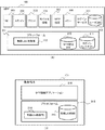
図2は、実施形態1に係るMFP100と携帯端末101のハードウェア構成を説明するブロック図である。
FIG. 2 is a block diagram illustrating a hardware configuration of
先ずMFP100のハードウェア構成を説明する。 First, the hardware configuration of MFP 100 will be described.
CPU201は、MFP100全体の動作を制御する。CPU201は、ROM202或いはHDD204に記憶された制御プログラムを読み出してRAM203に展開し、その展開したプログラムを実行して読取制御や送信制御などの各種制御を行う。RAM203は、CPU201が各種プログラムを実行するためのワークエリア等として使用する揮発性のメモリである。HDD204は、画像データや各種プログラムを記憶する。操作部205は、ユーザの指で操作可能なタッチパネル機能を備える表示部やハードキー等を備える。プリンタ206は、内部バスを介して転送された画像データに基づいて用紙(シート)に画像を印刷する。スキャナ207は、原稿の画像を読み取って画像データを生成する。ICカードリーダ208は、ユーザの認証に使用するICカードの読み取りを行う。有線LANI/F209は、有線のLANに接続するためのNIC(Network Interface Card)である。無線LANI/F210は、無線LANに対応した端末からMFP100に接続するためのアクセスポイントである。これらは内部バスを介して相互に接続されている。
次に携帯端末101のハードウェア構成を説明する。
Next, the hardware configuration of the
CPU211は、携帯端末101全体の動作を制御する。RAM212は、CPU211が各種プログラムを実行するためのワークエリア等として使用する揮発性のメモリである。フラッシュメモリ213は、各種プログラムやデータを記憶する不揮発性のメモリである。無線LANI/F214は、無線LANで通信するためのインタフェースであり、無線LANのアクセスポイントに接続して無線通信を行うことができる。実施形態1では、無線LANI/F214は、MFP100が備える無線LANI/F210と接続した後に、MFP100と相互に通信するために利用される。操作部215は、ユーザの指で操作可能なタッチパネルとして動作するディスプレイである。スピーカ216は、電気信号を音に変換する。マイク217は、音を検知して電気信号に変換する。カメラ218は、静止画や動画を撮影し、電子データに変換する。
The
次に図3を参照して実施形態1に係るMFP100と携帯端末101のソフトウェア構成を説明する。
Next, a software configuration of the
図3(A)は、実施形態1に係るMFP100のソフトウェア構成及びソフトウェアが管理するデータ領域を説明するブロック図である。尚、この図3(A)に示すソフトウェアの機能は、CPU201がRAM203に展開されたプログラムを実行することにより実現される。
FIG. 3A is a block diagram illustrating a software configuration of
図4は、実施形態1に係るMFP100の操作部205に表示するユーザインタフェースと画面遷移の一例を示す図である。以下、図3(A)と図4を参照しながら説明する。
FIG. 4 is a diagram illustrating an example of a user interface and screen transition displayed on the
プラットフォーム301は、MFP100を制御するソフトウェアの基本機能を提供するプラットフォームである。プラットフォーム301は、例えばLinux等のオペレーティングシステムや、JAVA(登録商標)のバーチャルマシンやOSGiフレームワーク、デバイスドライバ群を含む形で構成できる。OSGiフレームワークは、OSGi Alliance(標準化団体)が定義したJAVAベースのサービスプラットフォームである。プラットフォーム301は、各種ハードウェアを制御するためのデバイスドライバ群を備えており、プラットフォーム上で動作するアプリケーションに対してハードウェアを利用するためのAPIを提供する。プラットフォーム301は、無線LAN制御部302を備える。
The
無線LAN制御部302は、無線LANI/F210を無線LANのアクセスポイントとして起動するソフトウェア・アクセスポイントモードを備える。ソフトウェア・アクセスポイントモードで起動したアクセスポイントに携帯端末が接続してくると、その携帯端末にIPアドレスを割り当てるDHCP機能も備える。また無線LAN制御部302は、ソフトウェア・アクセスポイントモードの起動・停止制御や、アクセスポイントのSSID(識別情報)やパスフレーズを読み書きするAPIをアプリケーションに対して提供する。その他に図示していないが、プリンタ206を制御するプリンタモジュール、スキャナ207を制御するスキャナモジュールもプラットフォーム301内に存在する。また、プラットフォーム301は、MFP設定DB(データベース)310などのデータを読み書きするためのAPIをアプリケーションに提供する。
The wireless
なお、上述のソフトウェア・アクセスポイントモードは、MFP100が動作可能な、アクセスポイントを介さずに外部装置(例えば携帯端末101)と直接無線通信を実行する直接無線通信モード(ダイレクト無線通信機能)の一例である。直接無線通信モードはソフトウェア・アクセスポイントモードに限らず、Wi−Fi Direct等、他の無線通信方式であってもよい。MFP100が直接無線通信モードで動作する場合、MFP100がアクセスポイントとして振る舞う。
The software access point mode described above is an example of a direct wireless communication mode (direct wireless communication function) in which the
コピー303、スキャン304、プリント305、モバイル接続306は、プラットフォーム301上で動作するアプリケーションの一例である。これらのアプリケーションは、操作部205に各種アプリケーションの機能を提供するためのユーザインタフェースを表示する。例えば、コピー303は、プラットフォームを301介して、スキャナ207とプリンタ206を制御して、コピーを実行する機能を提供する。スキャン304は、スキャナ207を稼働して取得した電子データを外部に送信、或いは、HDD204に記憶する機能を提供する。プリント309は、外部から受信したプリントジョブの実行状態やプリント履歴を表示する機能を提供する。
The
モバイル接続306は、無線LANI/F210をアクセスポイントモードで利用するためのユーザインタフェース(図4のモバイル接続画面403)を提供する。ユーザは、モバイル接続画面403のアクセスポイント起動ボタン413を押下することにより、アドホックに無線LANのアクセスポイントを起動することができる。このとき、利用可能なアクセスポイントのSSIDとパスフレーズを、モバイル接続画面403のエリア415に表示する。例えば、携帯端末101のユーザは、そのエリア415に表示されたアクセスポイントのSSIDとパスフレーズを使って携帯端末101をアクセスポイントモードで稼働している無線LANI/F210に接続して、携帯端末からMFP100を利用できる。そして無線LANの利用が終了した場合は、ユーザは、アクセスポイント停止ボタン414を押下して、無線LANのアクセスポイントを停止する。これにより、携帯端末101との接続を終了することができる。
The
MFP設定307は、MFP100の管理者がMFP100の設定を行うためのMFP設定画面404(図4)を提供する。メニュー308は、操作部205から前述のアプリケーションを選択するためのメニュー画面402(図4)を表示するモジュールである。例えば、メニュー画面402は、各種アプリケーションが提供する機能を表示するボタン407〜410やMFP101の設定画面を表示するためのMFP設定ボタン411などを備える。ログインサービス309は、MFP100を利用するユーザのアカウント管理機能やログイン機能を備える。MFP設定DB310は、アプリケーションやMFP100の設定を一元管理するデータベースである。
The MFP setting 307 provides an MFP setting screen 404 (FIG. 4) for the administrator of the
実施形態1に係るMFP100の設定画面404を介して以下の設定ができるものとする。MFP100の設定画面404で設定された値は、MFP設定DB310に記憶される。
・ログイン機能のON/OFF(図4の設定画面404の416)
ログイン機能をOFFに設定した場合、ユーザはログイン操作を行うことなくメニュー画面402を表示して、そのメニュー画面で選択した機能を利用することができる。
The following settings can be made via the
ON / OFF of the login function (416 of the
When the login function is set to OFF, the user can display the
ログイン機能をONにした場合は、ログインサービス309が操作部205にログイン画面401(図4)を表示する。これによりユーザは、そのログイン画面401を介してログイン操作を行った後に、メニュー画面402及びそのメニュー画面402から選択した機能を利用することができる。
・アクセスポイントのデフォルトのSSIDとパスフレーズの設定(図4の設定画面404の417)
固定のSSIDとパスフレーズをMFP100に設定する。
・ワンタイムSSIDの利用設定(図4の設定画面404の418)
この設定がONの場合は、毎回異なるSSIDでアクセスポイントを起動する機能が有効となる。
・個人毎のSSIDの利用設定(図4の設定画面404の419)
この設定がONの場合は、ログイン機能と連動して、ユーザ毎に異なるSSIDでアクセスポイントを起動する機能が有効となる。
When the login function is turned on, the
Setting of default SSID and passphrase of access point (417 of
A fixed SSID and passphrase are set in
-Use setting of one-time SSID (418 of
When this setting is ON, the function of starting the access point with a different SSID every time becomes effective.
・ Use setting of SSID for each individual (419 of
When this setting is ON, the function of activating the access point with a different SSID for each user in conjunction with the login function is enabled.
ここでログインサービス309は、以下に説明するユーザアカウント管理機能やログイン機能を備える。
Here, the
ユーザアカウントの管理機能は、ユーザアカウントの登録や管理を行うユーザインタフェースをユーザに提供し、そのユーザインタフェースを介して登録されたユーザ情報をユーザDB312に記憶して管理する。ここで管理するユーザ情報は、例えば、表1のユーザ情報一覧に示すようなユーザ名、パスワード、ICカード番号、ロール等を含んでいる。
The user account management function provides a user with a user interface for registering and managing a user account, and stores and manages user information registered via the user interface in the

ログイン機能は、操作部205を利用するユーザに対してログイン/ログアウト機能を提供する。操作部205にログイン画面401を表示し、ログインしていないユーザが操作部205を利用できないようにしている。尚、このとき同時に操作部205にログインできるユーザの数を「1」とし、複数のユーザが同時に操作部205からログインできないようにしている。ユーザがログインに成功した場合は、操作部205の表示をログイン画面401からメニュー画面402に遷移させ、ユーザがMFP100を利用可能な状態にする。尚、このログインを行う手段としては複数のログイン手段がある。例えば、以下のようなログイン手段を提供する。
− キーボードログイン手段
操作部205のログイン画面401にソフトキーボードを表示し、ログインボタン405のボタンの押下を検知した場合には、入力されたユーザ名(アカウント)とパスワードを取得してユーザ認証し、ログイン処理を行う。
− ICカードログイン手段
ICカードリーダ208にかざされたICカードからICカード番号を取得して、ユーザを特定し、ログイン処理を行う。
The login function provides a user using the
-Keyboard login means A soft keyboard is displayed on the
-IC card login means Acquires an IC card number from an IC card held over the
通常、ログインサービスは、キーボードログイン手段やICカードログイン手段で取得したユーザ名とパスワード、或いはICカード番号がユーザDB312に登録されているものと一致するか照合することでユーザを認証する。またログインサービスは、有線LANで接続されたユーザ認証用のサーバと連携しても良い。この場合、ログインサービスが取得したユーザ名とパスワード、或いはICカード番号がサーバに登録されているものと一致するか照合することでユーザの認証を行う。ユーザ認証用のサーバには、LDAPサーバやWindows(商標)のActiveDirectory(商標)、独自のサーバなどを使用することが考えられる。
Normally, the login service authenticates the user by checking whether the user name and password acquired by the keyboard login unit or the IC card login unit, or the IC card number matches those registered in the
また実施形態1におけるログインサービスは、ゲストログイン機能を備える。ゲストログイン機能は、例えば、ログイン画面401にゲスト用のログインボタン406を表示する。このゲスト用のログインボタン406の押下を検知した場合は、ユーザの認証を行うことなく、そのユーザがMFP100を利用可能な状態にする。尚、ゲストがログインしたときは、MFP100の一部の機能を使えなくするなどしても良い。例えば、ゲストにはMFP100の設定変更をできないようにするためにMFP設定ボタン411を無効化する。またゲストにプリント用紙を使用させたくない場合は、コピーボタン407やプリントボタン409を無効化する等しても良い。
The login service according to the first embodiment has a guest login function. The guest login function displays a
ログインサービス309は、ユーザがログインすると、ログイン中のユーザの情報を記録したオブジェクトを生成してRAM203に記憶する。ログイン中のユーザの情報を記録したオブジェクトを、以下、ログインコンテキスト311と称す。このログインコンテキスト311に記録する情報の例を以下の表2に示す。
When the user logs in, the
ログインコンテキスト311には、ドメイン名を記録する領域を設けて、ユーザDB312に登録されたユーザアカウントと、ユーザ認証用のサーバで管理されたユーザアカウントを別のアカウントとして区別できるようにする。例えば、ユーザDB312に登録されたユーザ(Alice)がログインした場合は、ドメイン名を記録する領域に「localhost」という文字列を記録する。また或いはユーザ認証用のサーバで管理されたユーザアカウントでログインした場合には、ドメイン名を記録する領域にドメイン名やサーバ名を文字列として記録する。サーバで管理されたユーザアカウントでログインした場合のログインコンテキスト311に記録する情報の例を以下の表3に示す。表3は、例えば、ユーザDB312に登録されたユーザ(Alice)が、サーバで管理されたユーザアカウントでログインした場合を示し、ドメイン名を記録する領域にドメイン名(DomainA)が記録されている。
An area for recording a domain name is provided in the
また表4は、ゲストログイン時に、ログインコンテキスト311に記録する情報の一例を示す。
Table 4 shows an example of information recorded in the
ここではユーザ名が「Alice」で、ドメイン名は「localhost」、ロールは「ゲスト」に設定されている。 Here, the user name is “Alice”, the domain name is “localhost”, and the role is “guest”.
図4に示す操作部205に表示された画面のログアウトボタン412の押下を検知した場合は、ログインコンテキスト311に記録した情報を消去して、再び、ログイン画面401の表示に戻る。
When the press of the
図3(B)は、実施形態1に係る携帯端末101のソフトウェア構成及びソフトウェアが管理するデータ領域を示すブロック図である。図5は、実施形態1に係る携帯端末101の操作部215に表示されるユーザインタフェースの一例を示す図である。以下、図3(B)と図5を参照しながら説明する。尚、この図3(B)に示すソフトウェアの機能は、CPU211がRAM212に展開されたプログラムを実行することにより実現される。
FIG. 3B is a block diagram illustrating a software configuration of the
無線LAN情報315は、ソフトウェアがフラッシュメモリ213に記録して管理するデータのデータ領域を示す。プラットフォーム313は、例えばGoogle社のAndroid(商標)やアップル社のiOS(商標)などのプラットフォームで構成することができる。プラットフォーム313は、各種ハードウェアを制御するためのデバイスドライバ群を備えており、プラットフォーム313上で動作するアプリケーションに対して各種ハードウェアを利用するためのAPIを提供する。プラットフォーム313は、無線LAN制御部314を備える。無線LAN制御部314は、無線LANI/F214を制御するソフトウェアである。図5の無線LANの設定画面501は、プラットフォーム313が操作部215に表示する無線LANの設定画面の一例を示す。例えば、無線LAN制御部314が検索して発見した無線LANのアクセスポイントのSSIDをリスト502に表示する。ユーザは、このリスト502から任意のアクセスポイントを選択し、そのアクセスポイントのパスフレーズをエリア503に入力して接続ボタン504を押下する。こうして接続が成功すると、プラットフォーム313は、SSIDとパスフレーズを無線LAN情報315に記録する。プラットフォーム313は、携帯端末101の無線LAN機能が有効で、かつ無線LANに未接続の時には、過去に接続したことのある無線LANのアクセスポイントを自動的に検索する。そして、無線LAN情報315に記録したSSIDとパスフレーズで接続を試みる機能を備える。
The
携帯端末101は、種々のアプリケーションをインストールして、プラットフォーム313上で稼働させることができる。実施形態1では、予めMFP接続アプリケーション316がインストールされているものとする。図5のユーザインタフェース画面505は、MFP接続アプリケーション316が、操作部215に表示するユーザインタフェース画面の一例を示す。例えば、MFP接続アプリケーション316は、MFP100と無線LANで接続した後、その無線LANを介して、MFP100のプリンタ207やスキャナ206の機能を利用できる。例えば、画面505で、ユーザがプリントボタンにタッチすることにより、MFP100に対して印刷を指示することができる。
The
図6は、実施形態1に係るMFP100によるアクセスポイントの起動処理を説明するフローチャートである。尚、この処理を実行するプログラムはROM202或いはHDD204に記憶されており、実行時、RAM203に展開され、CPU201の制御の下に実行される。また、このフローチャートを実行するソフトウェアの主体は、図3(A)のソフトウェア構成で示すと無線LAN制御部302である。
FIG. 6 is a flowchart illustrating an access point activation process performed by
この処理は、ユーザがモバイル接続画面403でアクセスポイント起動ボタン413を押下すると、モバイル接続306が無線LAN制御部302にアクセスポイントの起動を要求する。こうして無線LAN制御部302が、アクセスポイントの起動要求を受付けることによりS601で開始される。尚、既にアクセスポイントが起動している場合は、現在起動しているアクセスポイントを停止してから、この処理を開始しても良い。
In this process, when the user presses the access
次にS602に進みCPU201は、MFP設定DB310を参照して、MFPの設定画面404を介して設定された個人毎のSSIDの利用設定419を取得する。そしてS603に進みCPU201は、S602で取得した設定419がONか否かを判定する。ここで個人毎のSSIDの利用設定がON、即ち、ユーザのログイン機能と連動して、ユーザ毎に異なるSSIDでアクセスポイントを起動するように設定されているとS604に進む。S604でCPU201は、ログインコンテキスト311を参照して、ログイン中のユーザ情報の取得を試みる。そしてS605に進みCPU201は、ログイン中のユーザ情報が取得できたか否かを判定し、ゲスト以外のログイン中のユーザ情報の取得に成功した場合はS606に進み、CPU201は、その取得したユーザ専用のSSIDとパスフレーズを生成する。尚、このときログインしたユーザ専用のSSIDとパスフレーズ生成のために、取得したユーザ情報が同じであれば、常に同じSSIDとパスフレーズが生成されるようなアルゴリズムを採用すると良い。ユーザ情報から常に同じ個人毎のSSIDとパスフレーズを生成する方法については後述する。そしてS607に進みCPU201は、生成もしくは取得したSSIDとパスフレーズでアクセスポイントを起動する。そしてS608に進みCPU201は、アクセスポイントの起動処理を終了する。
Next, the processing proceeds to step S <b> 602, and the
一方、S603で個人毎のSSIDの利用設定416がOFFの場合、或いはS605でログイン中のユーザ情報がゲストを示す場合、或いはログイン中のユーザ情報が取得できなかった場合はS609に進む。S609でCPU201は、MFP設定DB310を参照して、ワンタイムのSSIDの利用設定418を取得する.次にS610に進みCPU201は、その取得した設定418がONか否かを判定する。ここでCPU201が、ワンタイムのSSIDの利用設定418がONである、即ち、毎回異なるSSIDでアクセスポイントを起動する設定であると判定するとS611に進む。S611でCPU201は、ワンタイムのSSIDとパスフレーズとして、乱数生成器を用いてランダムなSSIDとパスフレーズを、その都度生成する。そしてS612に進みCPU201は、その生成したワンタイムのSSIDとパスフレーズでアクセスポイントを起動する。そしてS608に進んで、アクセスポイントの起動処理を終了する。
On the other hand, if the SSID usage setting 416 for each individual is OFF in S603, or if the logged-in user information indicates a guest in S605, or if the logged-in user information cannot be acquired, the process proceeds to S609. In step S609, the
またS610でCPU201は、ワンタイムのSSIDの利用設定418がOFFであると判定した場合はS613に進みCPU201は、MFP設定DB310を参照して、デフォルトのSSIDとパスフレーズを取得する。次にS614に進みCPU201は、デフォルトのSSIDとパスフレーズでアクセスポイント起動する。そしてS608に進んでアクセスポイントの起動処理を終了する。尚、起動したアクセスポイントのSSIDとパスフレーズは、図4のモバイル接続画面403に表示してもよい。
If the
但し、ユーザ毎のSSIDとパスフレーズは、他の人に見られないようにするため、アクセスポイントが起動中であっても、ゲストや他の人がログインした場合やログイン機能がOFFに変更された場合は、モバイル接続画面403に表示しないように制御する。
However, in order to prevent the SSID and passphrase for each user from being seen by other people, even if the access point is running, if a guest or other person logs in, or the login function is changed to OFF. In this case, control is performed so as not to be displayed on the
尚、上述のフローチャートでは、S604で取得したログイン中のユーザ情報がゲストを示す場合には、S609に進むように構成した。しかし、ゲスト用のアカウントを通常のアカウントと同様の扱いにする場合は、S606に進んで、ゲスト専用のSSIDとパスフレーズを生成或いは取得するようにしても良い。 In the above-described flowchart, when the logged-in user information acquired in S604 indicates a guest, the process proceeds to S609. However, when the guest account is to be treated in the same manner as a normal account, the process may proceed to S606 to generate or acquire a guest-specific SSID and passphrase.
またMFP100のログイン機能の設定416がOFFの場合には、S605でログイン中のユーザ情報の取得に失敗したと判定されるため、個人毎のSSIDの利用設定419がONであっても、個人毎のSSIDが使用されることは無い。
If the setting 416 of the login function of the
図7は、実施形態1に係るMFP100で、ログインしたユーザの情報が以前にログインしたユーザの情報と同じであるときに、同じSSIDとパスフレーズが生成されるアルゴリズムを説明する図である。尚、以下の説明はあくまでも一例であって、生成方法はこの限りでは無い。
FIG. 7 is a diagram illustrating an algorithm for generating the same SSID and passphrase in
例えばSSIDにユーザ名やドメイン名を使用すると、ユーザにとって分かりやすいSSIDを生成することができる。例えば、701は、ユーザ名とドメイン名に固定の接続文字(−)や、接尾文字(−AP)を加えて一つの文字列としてSSIDを生成する例を示している。
For example, if a user name or a domain name is used for the SSID, an SSID that is easy for the user to understand can be generated. For example,
また、ユーザ専用のパスフレーズ、或いはSSIDとパスフレーズの両方を、他人から推測できないような秘匿性のものにしたい場合は、次のような方法が考えられる。例えば、例えば図7の702や703で示すように、ユーザ名とドメイン名を含む文字列をメッセージ710とし、MFP固有の値を鍵711として、RFC2104で知られるHMACのアルゴリズムを用いてMAC値712,713を算出する。次に、このMAC値を文字列化して、SSIDやパスフレーズに使用する。702の例では、HMACを用いてパスフレーズ716のみを生成した場合を示している。また703の例では、HMACを用いてSSID714とパスフレーズ715の両方を生成した場合の例を示している。703の例では、長めの文字列717を生成して、前方の文字列をSSID714、後方の文字列をパスフレーズ715としている。
Further, when it is desired to make the user-specific passphrase or both the SSID and the passphrase confidential so as not to be guessed by others, the following method is conceivable. For example, as shown by
また実施形態1に係るMFPが同一オフィスに複数ある場合は、複数のMFPでHMACに使用する鍵情報を共有して、ユーザ情報が同じであれば、同一のSSIDとパスフレーズを生成するようにしても良い。こうして複数のMFPで同一のSSIDとパスフレーズが利用できるようになると、ユーザが携帯端末101に、MFP毎に異なるSSIDとパスフレーズを登録する煩わしさを軽減することができる。またユーザが複数のMFPを同時に使うことがなければ、複数のMFPで同一のSSIDとパスフレーズを持つアクセスポイントが同時に起動することがないため問題は生じない。
When there are a plurality of MFPs according to the first embodiment in the same office, the key information used for the HMAC is shared by the plurality of MFPs, and the same SSID and passphrase are generated if the user information is the same. May be. When the same SSID and passphrase can be used in a plurality of MFPs in this way, the trouble of the user registering a different SSID and passphrase in the
以上説明したように本実施形態1によれば、ユーザがMFPにログインしてアクセスポイントを起動した場合、そのログインしたユーザ専用のSSIDとパスフレーズでアクセスポイントを起動することができる。このときユーザ専用のSSIDとパスフレーズは、アクセスポイントの起動や停止する度に変化することがないため、同一ユーザであれば、常に同じSSIDとパスフレーズが使えることになる。これにより、携帯端末へのSSIDとパスフレーズの登録が一回で済むため、ユーザの手間を軽減できる。 As described above, according to the first embodiment, when the user logs in to the MFP and starts the access point, the access point can be started with the SSID and passphrase dedicated to the logged-in user. At this time, the user-specific SSID and passphrase do not change each time the access point is started or stopped, so that the same user can always use the same SSID and passphrase. As a result, the registration of the SSID and the passphrase in the mobile terminal can be performed only once, thereby reducing the user's labor.
また、ユーザ専用のSSIDとパスフレーズを他人に知られないようにすることで、MFPにログインしてアクセスポイントを起動したユーザは、そのアクセスポイントを他人により使用されることがない。これによりユーザは、一時的に、MFPが起動したアクセスポイントを占有することができる。 Also, by keeping the SSID and passphrase exclusive for the user from being known to others, a user who logs in to the MFP and activates the access point will not use the access point by others. Thereby, the user can temporarily occupy the access point activated by the MFP.
更に、この機能は、携帯端末が過去に接続したことがあるアクセスポイントと自動接続する機能と共に使用することで、更なる効果を得ることができる。つまり、一旦、携帯端末のユーザは、その携帯端末にユーザ専用のSSIDとパスフレーズを登録して記憶させると、次回からそのユーザは、MFPにログインしてアクセスポイントを起動するだけで、携帯端末とMFPを接続することができる。 Further, by using this function together with the function of automatically connecting the mobile terminal to an access point to which the mobile terminal has been connected in the past, a further effect can be obtained. In other words, once the user of the mobile terminal registers and stores the user-specific SSID and passphrase in the mobile terminal, the user only needs to log in to the MFP and start the access point from the next time. And the MFP.
また、MFPのログイン機能がONであっても、ゲストがユーザ認証をすることなく、MFPを利用するケースがある。このため、ゲストがMFPのアクセスポイントを利用する場合には、テンポラリのSSIDとパスフレーズを提供するようにした。これにより、ゲストであっても他人にアクセスポイントを使われることなく、一時的にMFPが起動したアクセスポイントを占有することができる。 Also, there is a case where the guest uses the MFP without user authentication even when the login function of the MFP is ON. For this reason, when the guest uses the access point of the MFP, a temporary SSID and a passphrase are provided. This allows the guest to temporarily occupy the access point activated by the MFP without being used by another person even if the guest is the guest.
また、MFPのログイン機能を常にONにしておくのが煩わしいと感じるユーザもいる。このため、ログイン機能がOFFの場合には、デフォルトのSSID或いはテンポラリのSSIDでMFPのアクセスポイントが利用できるようにした。 Further, some users find it difficult to always keep the login function of the MFP ON. Therefore, when the login function is OFF, the access point of the MFP can be used with the default SSID or the temporary SSID.
また、MFPのアクセスポイントに同時に接続できる最大端末数より、実際に使用する端末の数の方が少ない場合は、個人毎のSSIDは使用せず、常にMFPのアクセスポイントをデフォルトのSSIDとパスフレーズで起動して良い場合もある。このため、個人毎のSSIDの利用設定をOFFにできるように構成した。 If the number of terminals actually used is smaller than the maximum number of terminals that can be simultaneously connected to the MFP access point, the SSID for each individual is not used, and the MFP access point is always set to the default SSID and passphrase. You may be able to start with For this reason, the configuration is such that the use setting of the SSID for each individual can be turned off.
[実施形態2]
次に本発明の実施形態2を説明する。実施形態2は、個人毎のSSIDをMFP100のHDD204に記録して管理する形態で説明する。尚、実施形態2に係るMFP100と携帯端末101のハードウェア構成、印刷システムの構成などは前述の実施形態1と同じであるため、その説明を省略する。
[Embodiment 2]
Next, a second embodiment of the present invention will be described. In the second embodiment, a description will be given of a mode in which the SSID of each individual is recorded in the
図8は、実施形態2に係るMFP100のソフトウェア構成及びソフトウェアが管理するデータ領域を示すブロック図である。尚、前述の実施形態1の図3(A)と共通する部分は同じ参照番号で示し、それらの説明を省略する。
FIG. 8 is a block diagram illustrating a software configuration of the
ここでプラットフォーム301は、個人毎のSSIDを、HDD204のSSID管理テーブル801に記録して管理する。例えばSSID管理テーブル801には、以下の表5に示すように、ユーザを一意に特定する情報(ユーザの名称とドメイン名)と関連付けてSSIDとパスフレーズを記憶する。
Here, the
図9は、実施形態2において、SSIDの編集や削除に対応したモバイル接続306が提供するユーザインタフェースの一例を示す図である。尚、図9において、図4と共通する部分は同じ番号を付している。
FIG. 9 is a diagram illustrating an example of a user interface provided by the
モバイル接続306は、ログインコンテキスト311を参照して、ログイン中のユーザを特定し、更に、SSID管理テーブル801から、ログイン中のユーザと関連付いたSSIDとパスフレーズを取得してエリア415に表示する。
The
図9において、モバイル接続画面403は、前述の図4と同様にエリア415にアクセスポイント情報を表示している。SSID管理テーブル801にログイン中のユーザと関連付けられたSSIDとパスフレーズの情報がない場合は、エリア415は空欄のまま表示される。モバイル接続306は、モバイル接続画面403の編集ボタン901の押下を検知した場合は、エリア415に表示中のSSIDとパスフレーズを編集するための編集画面903を表示する。ユーザは、この編集画面903のエリア904に新たなSSIDとパスフレーズを入力して更新ボタン905を押下することにより、新たなSSIDとパスフレーズを登録することができる。この際、モバイル接続306は、新たにエリア904に入力されたSSIDとパスフレーズを取得して、SSID管理テーブル801に登録或いは更新する。このようにして、ユーザの識別情報に所定の文字列を連結することで、新たなSSIDを生成することができる。
In FIG. 9, the
またモバイル接続画面403は、削除ボタン902を備える。モバイル接続306は、モバイル接続画面403の削除ボタン902の押下を検知すると、SSID管理テーブル801から、ログイン中のユーザと関連付いたSSIDとパスフレーズの情報を削除する。
The
図10は、実施形態2に係るMFP100によるアクセスポイントの起動処理を説明するフローチャートである。尚、この処理を実行するプログラムはROM202或いはHDD204に記憶されており、実行時、RAM203に展開され、CPU201の制御の下に実行される。また、このフローチャートを実行するソフトウェアの主体は、図8のソフトウェア構成で示すと無線LAN制御部302である。尚、図10において、前述の実施形態1に係るフローチャートと共通する部分は同じ記号で示している。
FIG. 10 is a flowchart illustrating access point activation processing by
S605においてCPU201は、ログインコンテキスト311からログイン中のユーザの情報が取得できたか否かを判定する。ここでログイン中のユーザの情報が取得できたと判定するとS1001に進みCPU201は、SSID管理テーブル801を参照して、ログイン中のユーザの情報と関連付いたSSIDとパスフレーズの取得を試みる。そしてS1002に進みCPU201は、SSIDとパスフレーズの取得に成功したか否かを判定する。ここで取得に失敗したと判定するとS1003に進みCPU201は、図7を参照して説明したように、ログイン中のユーザ情報を用いて、新たにSSIDとパスフレーズを生成する。そしてログイン中のユーザの情報と関連付けてSSID管理テーブル801に記憶してS1004に進む。S1004でCPU201は、S1003で生成したSSIDとパスフレーズを用いてアクセスポイントを起動して、アクセスポイントの起動処理を完了する。
In step S <b> 605, the
一方、S1002でCPU201は、SSIDとパスフレーズの取得に成功したときはS1004に進む。S1004でCPU201は、SSID管理テーブル801から取得したSSIDとパスフレーズを用いてアクセスポイントを起動して、このアクセスポイントの起動処理を完了する。
On the other hand, if the
以上説明したように実施形態2によれば、SSID管理テーブル801にSSIDとパスフレーズが記憶されていなければ、新たにSSIDを生成してSSID管理テーブル801に記憶するとともに、それを使用してアクセスポイントを起動する。一方、既に記憶されたSSIDとパスフレーズがあれば、これを使用してアクセスポイントを起動する。これにより、SSIDやパスフレーズの生成に係るCPUの負荷を軽減することができる。 As described above, according to the second embodiment, if the SSID and the passphrase are not stored in the SSID management table 801, a new SSID is generated and stored in the SSID management table 801, and access is performed using the generated SSID. Activate point. On the other hand, if there is an already stored SSID and passphrase, the access point is activated using these. Thus, the load on the CPU for generating the SSID and the passphrase can be reduced.
また、ユーザが自分用のSSIDとパスフレーズを編集可能にすることにより、ユーザが自由に所望のSSIDとパスフレーズを設定することができ、MFPの利便性が向上する。また、個人毎のSSIDとパスフレーズが他人に漏洩してしまった場合でも、ユーザが任意のタイミングで、SSIDとパスフーズを変更或いは削除できるため、MFPのセキュリティを保つことができる。 Further, by allowing the user to edit his / her own SSID and passphrase, the user can freely set a desired SSID and passphrase, and the convenience of the MFP is improved. Further, even when the SSID and passphrase for each individual are leaked to another person, the user can change or delete the SSID and passfood at an arbitrary timing, so that the security of the MFP can be maintained.
(その他の実施形態)
本発明は、上述の実施形態の1以上の機能を実現するプログラムを、ネットワーク又は記憶媒体を介してシステム又は装置に供給し、そのシステム又は装置のコンピュータにおける1つ以上のプロセッサーがプログラムを読出し実行する処理でも実現可能である。また、1以上の機能を実現する回路(例えば、ASIC)によっても実現可能である。
(Other embodiments)
The present invention supplies a program for realizing one or more functions of the above-described embodiments to a system or an apparatus via a network or a storage medium, and one or more processors in a computer of the system or the apparatus read and execute the program. This processing can be realized. Further, it can also be realized by a circuit (for example, an ASIC) that realizes one or more functions.
本発明は上記実施の形態に制限されるものではなく、本発明の精神及び範囲から離脱することなく、様々な変更及び変形が可能である。従って、本発明の範囲を公にするために、以下の請求項を添付する。 The present invention is not limited to the above embodiments, and various changes and modifications can be made without departing from the spirit and scope of the present invention. Therefore, to make the scope of the present invention public, the following claims are appended.
100…MFP,101…携帯端末、201…CPU、205…操作部、208…ICカードリーダ、301…プラットフォーム、302…無線LAN制御部、311…ログインコンテキスト 100 MFP, 101 mobile terminal, 201 CPU, 205 operating unit, 208 IC card reader, 301 platform, 302 wireless LAN control unit, 311 login context
Claims (15)
前記ダイレクト無線通信に使用される複数のSSIDを、複数のユーザの識別情報のそれぞれに対応付けて記憶する記憶手段と、
ユーザにより操作される操作手段と、
前記操作手段を介したユーザ操作によって受け付けた情報に基づいて、前記通信装置のユーザを特定する特定手段と、
前記特定手段によって特定された前記ユーザの識別情報に対応付けて記憶されたSSIDを、前記記憶手段に記憶された前記複数のSSIDから選択する選択手段と、
前記選択手段によって選択された前記SSIDを使用して前記ダイレクト無線通信を実行する無線通信手段と、
を備えることを特徴とする通信装置。 A communication device that performs direct wireless communication with an external device,
Storage means for storing a plurality of SSIDs used for the direct wireless communication in association with each of a plurality of user identification information,
Operating means operated by the user;
Identification means for identifying a user of the communication device based on information received by a user operation via the operation means,
Selecting means for selecting an SSID stored in association with the identification information of the user specified by the specifying means from the plurality of SSIDs stored in the storage means;
Wireless communication means for performing the direct wireless communication using the SSID selected by the selection means,
A communication device comprising:
前記ダイレクト無線通信に使用される複数のSSIDを、複数のユーザの識別情報のそれぞれに対応付けて記憶する記憶手段と、Storage means for storing a plurality of SSIDs used for the direct wireless communication in association with each of a plurality of user identification information,
ユーザが所持する集積回路を有するデバイスから情報を取得する取得手段と、Acquiring means for acquiring information from a device having an integrated circuit owned by a user;
前記取得手段によって取得された情報に基づいて前記通信装置のユーザを特定する特定手段と、Specifying means for specifying the user of the communication device based on the information obtained by the obtaining means,
前記特定手段によって特定された前記ユーザの識別情報に対応付けて記憶されたSSIDを、前記記憶手段に記憶された前記複数のSSIDから選択する選択手段と、Selecting means for selecting an SSID stored in association with the identification information of the user specified by the specifying means from the plurality of SSIDs stored in the storage means;
前記選択手段によって選択された前記SSIDを使用して前記ダイレクト無線通信を実行する無線通信手段と、Wireless communication means for performing the direct wireless communication using the SSID selected by the selection means,
を備えることを特徴とする通信装置。A communication device comprising:
前記取得手段は、ICカードリーダーを含むことを特徴とする請求項2に記載の通信装置。The communication device according to claim 2, wherein the acquisition unit includes an IC card reader.
前記記憶手段は、前記特定手段によって特定された前記ユーザの識別情報と、前記生成手段によって生成された前記SSIDとを対応付けて記憶することを特徴とする請求項1乃至4のいずれか1項に記載の通信装置。 The apparatus further includes a generation unit that generates an SSID of the user specified by the specification unit,
5. The storage device according to claim 1, wherein the storage unit stores identification information of the user specified by the specifying unit and the SSID generated by the generation unit in association with each other. 6. The communication device according to claim 1.
前記ダイレクト無線通信に使用される複数のSSIDを、複数のユーザの識別情報のそれぞれに対応付けて記憶部に記憶する記憶工程と、
前記通信装置の操作部を介したユーザ操作によって受け付けた情報に基づいて、前記通信装置のユーザを特定する特定工程と、
前記特定工程で特定された前記ユーザの識別情報に対応付けて記憶されたSSIDを、前記記憶部に記憶されたSSIDから選択する選択工程と、
前記選択工程で選択された前記SSIDを使用して前記ダイレクト無線通信を実行する無線通信工程と、
を備えることを特徴とする通信装置の制御方法。 A control method for controlling a communication device that performs direct wireless communication with an external device,
A storage step of storing a plurality of SSIDs used for the direct wireless communication in a storage unit in association with each of a plurality of user identification information;
A specifying step of specifying a user of the communication device based on information received by a user operation via an operation unit of the communication device,
A selecting step of selecting an SSID stored in association with the identification information of the user specified in the specifying step from the SSID stored in the storage unit;
A wireless communication step of performing the direct wireless communication using the SSID selected in the selection step,
A method for controlling a communication device, comprising:
前記ダイレクト無線通信に使用される複数のSSIDを、複数のユーザの識別情報のそれぞれに対応付けてメモリに記憶する記憶工程と、A storage step of storing a plurality of SSIDs used for the direct wireless communication in a memory in association with each of a plurality of user identification information;
ユーザが所持する集積回路を有するデバイスから情報を取得する取得工程と、An acquisition step of acquiring information from a device having an integrated circuit owned by a user,
前記取得工程で取得された情報に基づいて前記通信装置のユーザを特定する特定工程と、A specifying step of specifying a user of the communication device based on the information acquired in the acquiring step,
前記特定工程で特定された前記ユーザの識別情報に対応付けて記憶されたSSIDを、前記メモリに記憶された前記複数のSSIDから選択する選択工程と、A selecting step of selecting, from the plurality of SSIDs stored in the memory, an SSID stored in association with the identification information of the user specified in the specifying step;
前記選択工程で選択された前記SSIDを使用して前記ダイレクト無線通信を実行する無線通信工程と、A wireless communication step of performing the direct wireless communication using the SSID selected in the selection step,
を備えることを特徴とする通信装置の制御方法。A method for controlling a communication device, comprising:
Priority Applications (1)
| Application Number | Priority Date | Filing Date | Title |
|---|---|---|---|
| JP2017122470A JP6643280B2 (en) | 2017-06-22 | 2017-06-22 | Communication device, control method therefor, and program |
Applications Claiming Priority (1)
| Application Number | Priority Date | Filing Date | Title |
|---|---|---|---|
| JP2017122470A JP6643280B2 (en) | 2017-06-22 | 2017-06-22 | Communication device, control method therefor, and program |
Related Parent Applications (1)
| Application Number | Title | Priority Date | Filing Date |
|---|---|---|---|
| JP2015081232A Division JP6166746B2 (en) | 2015-04-10 | 2015-04-10 | COMMUNICATION DEVICE, ITS CONTROL METHOD, AND PROGRAM |
Publications (3)
| Publication Number | Publication Date |
|---|---|
| JP2017188951A JP2017188951A (en) | 2017-10-12 |
| JP2017188951A5 JP2017188951A5 (en) | 2018-05-31 |
| JP6643280B2 true JP6643280B2 (en) | 2020-02-12 |
Family
ID=60045816
Family Applications (1)
| Application Number | Title | Priority Date | Filing Date |
|---|---|---|---|
| JP2017122470A Active JP6643280B2 (en) | 2017-06-22 | 2017-06-22 | Communication device, control method therefor, and program |
Country Status (1)
| Country | Link |
|---|---|
| JP (1) | JP6643280B2 (en) |
Families Citing this family (1)
| Publication number | Priority date | Publication date | Assignee | Title |
|---|---|---|---|---|
| US11616784B2 (en) * | 2019-07-11 | 2023-03-28 | Kyndryl, Inc. | Personal-public service set identifiers connection implemented by a WAP |
-
2017
- 2017-06-22 JP JP2017122470A patent/JP6643280B2/en active Active
Also Published As
| Publication number | Publication date |
|---|---|
| JP2017188951A (en) | 2017-10-12 |
Similar Documents
| Publication | Publication Date | Title |
|---|---|---|
| US10901662B2 (en) | Communication apparatus, method of controlling the same, and storage medium | |
| JP6659170B2 (en) | Information processing apparatus, information processing method and program | |
| US20140380462A1 (en) | Image processing apparatus that performs user authentication, authentication method therefor, and storage medium | |
| JP6525493B2 (en) | IMAGE PROCESSING APPARATUS, AUTHENTICATION METHOD THEREOF, AND PROGRAM | |
| JP7312212B2 (en) | Information processing device, its control method, and program | |
| JP2017212694A (en) | Information processing device, information processing method and program | |
| KR20180085354A (en) | Image processing apparatus, control method thereof, and storage medium | |
| JP6643280B2 (en) | Communication device, control method therefor, and program | |
| JP2019068219A (en) | Information processing apparatus, control method thereof, and program | |
| US20180048642A1 (en) | Wireless network apparatus, wireless network system, and non-transitory computer readable medium | |
| JP6929632B2 (en) | Communication equipment, control methods and programs for communication equipment | |
| JP7191189B2 (en) | Information processing device, its control method, and program | |
| JP2018033003A (en) | Information processing device, control method thereof, and program | |
| JP6993890B2 (en) | Information processing equipment, its control method, and programs | |
| JP6919251B2 (en) | Information processing equipment and programs | |
| JP2022179594A (en) | Image processing device, image processing device control method, and program |
Legal Events
| Date | Code | Title | Description |
|---|---|---|---|
| A521 | Written amendment |
Free format text: JAPANESE INTERMEDIATE CODE: A523 Effective date: 20180410 |
|
| A621 | Written request for application examination |
Free format text: JAPANESE INTERMEDIATE CODE: A621 Effective date: 20180410 |
|
| A131 | Notification of reasons for refusal |
Free format text: JAPANESE INTERMEDIATE CODE: A131 Effective date: 20190607 |
|
| A521 | Written amendment |
Free format text: JAPANESE INTERMEDIATE CODE: A523 Effective date: 20190717 |
|
| TRDD | Decision of grant or rejection written | ||
| A01 | Written decision to grant a patent or to grant a registration (utility model) |
Free format text: JAPANESE INTERMEDIATE CODE: A01 Effective date: 20191206 |
|
| A61 | First payment of annual fees (during grant procedure) |
Free format text: JAPANESE INTERMEDIATE CODE: A61 Effective date: 20200106 |
|
| R151 | Written notification of patent or utility model registration |
Ref document number: 6643280 Country of ref document: JP Free format text: JAPANESE INTERMEDIATE CODE: R151 |