JP6642414B2 - Gaming machine - Google Patents
Gaming machine Download PDFInfo
- Publication number
- JP6642414B2 JP6642414B2 JP2016254613A JP2016254613A JP6642414B2 JP 6642414 B2 JP6642414 B2 JP 6642414B2 JP 2016254613 A JP2016254613 A JP 2016254613A JP 2016254613 A JP2016254613 A JP 2016254613A JP 6642414 B2 JP6642414 B2 JP 6642414B2
- Authority
- JP
- Japan
- Prior art keywords
- main body
- arm
- ball
- plate
- state
- Prior art date
- Legal status (The legal status is an assumption and is not a legal conclusion. Google has not performed a legal analysis and makes no representation as to the accuracy of the status listed.)
- Active
Links
Images


Description
本発明は、パチンコ機などの遊技機に関するものである。 The present invention relates to a gaming machine such as a pachinko machine.
パチンコ機等の遊技機において、背面ケースから移動部材まで電気配線が支え無しで配設される遊技機がある(特許文献1)。 2. Description of the Related Art In a gaming machine such as a pachinko machine, there is a gaming machine in which electric wiring is arranged without support from a rear case to a moving member (Patent Document 1).
しかしながら、上述した従来の遊技機では、配線の配設の仕方に関して改良の余地があるという問題点があった。 However, in the above-mentioned conventional gaming machine, there is a problem that there is room for improvement in the way of wiring.
本発明は、上記例示した問題点を解決するためになされたものであり、配線を適切に配設できる遊技機を提供することを目的とする。 The present invention has been made in order to solve the above-described problems, and has as its object to provide a gaming machine in which wiring can be appropriately arranged.
この目的を達成するために請求項1記載の遊技機は、移動可能な移動部材と、その移動部材に接続される配線と、を備える遊技機であって、一方の端部が前記移動部材に連結される配線補助部材を備え、前記配線は、少なくとも一部が前記配線補助部材に沿って配設され、前記配線補助部材は、複数の構成部を備え、その構成部は、長尺の長尺部と、その長尺部の少なくとも一方の端部に形成され前記構成部同士を回転可能に支持する支持部と、を備え、前記長尺部の少なくとも一部は、長尺方向に沿って並設される一対の側壁部を備え、前記側壁部の少なくとも一方は、前記配線に向かって突設される突設部を備える。 In order to achieve this object, a game machine according to claim 1 is a game machine including a movable moving member and a wire connected to the moving member, one end of which is connected to the moving member. A wiring auxiliary member connected to the wiring, at least a part of the wiring is disposed along the wiring auxiliary member, and the wiring auxiliary member includes a plurality of constituent parts, and the constituent parts are long and long. A long portion, and a supporting portion formed at at least one end of the long portion and rotatably supporting the components, and at least a part of the long portion extends along the long direction. A pair of side wall portions are provided side by side, and at least one of the side wall portions includes a projecting portion projecting toward the wiring.
請求項2記載の遊技機は、請求項1記載の遊技機において、基板ボックスを備える。A gaming machine according to a second aspect is the gaming machine according to the first aspect, further comprising a board box.
請求項1記載の遊技機によれば、遊技機の配線を適切に配設することができる。 According to the gaming machine of the first aspect, it is possible to appropriately arrange the wiring of the gaming machine.
請求項2記載の遊技機によれば、請求項1記載の遊技機の奏する効果に加え、基板ボックスの内部に制御装置を収納することができる。According to the gaming machine of the second aspect, in addition to the effects achieved by the gaming machine of the first aspect, a control device can be housed inside the board box.
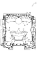
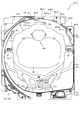
以下、本発明の実施形態について、添付図面を参照して説明する。まず、図1から図50を参照し、第1実施形態として、本発明をパチンコ遊技機(以下、単に「パチンコ機」という)10に適用した場合の一実施形態について説明する。図1は、第1実施形態におけるパチンコ機10の正面図であり、図2はパチンコ機10の遊技盤13の正面図であり、図3はパチンコ機10の背面図である。
Hereinafter, embodiments of the present invention will be described with reference to the accompanying drawings. First, an embodiment in which the present invention is applied to a pachinko gaming machine (hereinafter, simply referred to as “pachinko machine”) 10 will be described as a first embodiment with reference to FIGS. 1 to 50. FIG. 1 is a front view of the
図1に示すように、パチンコ機10は、略矩形状に組み合わせた木枠により外殻が形成される外枠11と、その外枠11と略同一の外形形状に形成され外枠11に対して開閉可能に支持された内枠12とを備えている。外枠11には、内枠12を支持するために正面視(図1参照)左側の上下2カ所に金属製のヒンジ18が取り付けられ、そのヒンジ18が設けられた側を開閉の軸として内枠12が正面手前側へ開閉可能に支持されている。
As shown in FIG. 1, the
内枠12には、多数の釘や入賞口63,64等を有する遊技盤13(図2参照)が裏面側から着脱可能に装着される。この遊技盤13の正面を球(遊技球)が流下することにより弾球遊技が行われる。なお、内枠12には、球を遊技盤13の正面領域に発射する球発射ユニット112a(図4参照)やその球発射ユニット112aから発射された球を遊技盤13の正面領域まで誘導する発射レール(図示せず)等が取り付けられている。
A game board 13 (see FIG. 2) having a large number of nails, winning
内枠12の正面側には、その正面上側を覆う正面枠14と、その下側を覆う下皿ユニット15とが設けられている。正面枠14及び下皿ユニット15を支持するために正面視(図1参照)左側の上下2カ所に金属製のヒンジ19が取り付けられ、そのヒンジ19が設けられた側を開閉の軸として正面枠14及び下皿ユニット15が正面手前側へ開閉可能に支持されている。なお、内枠12の施錠と正面枠14の施錠とは、シリンダ錠20の鍵穴21に専用の鍵を差し込んで所定の操作を行うことでそれぞれ解除される。
On the front side of the
正面枠14は、装飾用の樹脂部品や電気部品等を組み付けたものであり、その略中央部には略楕円形状に開口形成された窓部14cが設けられている。正面枠14の裏面側には2枚の板ガラスを有するガラスユニット16が配設され、そのガラスユニット16を介して遊技盤13の正面がパチンコ機10の正面側に視認可能となっている。
The
正面枠14には、球を貯留する上皿17が正面側へ張り出して上面を開放した略箱状に形成されており、この上皿17に賞球や貸出球などが排出される。上皿17の底面は正面視(図1参照)右側に下降傾斜して形成され、その傾斜により上皿17に投入された球が球発射ユニット112a(図4参照)へと案内される。また、上皿17の上面には、枠ボタン22が設けられている。この枠ボタン22は、例えば、第3図柄表示装置81(図2参照)で表示される演出のステージを変更したり、スーパーリーチの演出内容を変更したりする場合などに、遊技者により操作される。
On the
正面枠14には、その周囲(例えばコーナー部分)に各種ランプ等の発光手段が設けられている。これら発光手段は、大当たり時や所定のリーチ時等における遊技状態の変化に応じて、点灯又は点滅することにより発光態様が変更制御され、遊技中の演出効果を高める役割を果たす。窓部14cの周縁には、LED等の発光手段を内蔵した電飾部29〜33が設けられている。パチンコ機10においては、これら電飾部29〜33が大当たりランプ等の演出ランプとして機能し、大当たり時やリーチ演出時等には内蔵するLEDの点灯や点滅によって各電飾部29〜33が点灯または点滅して、大当たり中である旨、或いは大当たり一歩手前のリーチ中である旨が報知される。また、正面枠14の正面視(図1参照)左上部には、LED等の発光手段が内蔵され賞球の払い出し中とエラー発生時とを表示可能な表示ランプ34が設けられている。
Light emitting means such as various lamps is provided around the front frame 14 (for example, at a corner). These light-emitting means are controlled to change the light-emitting mode by lighting or blinking according to a change in the game state at the time of a big hit or at a predetermined reach, and play a role of enhancing the effect of the effect during the game. On the periphery of the
また、右側の電飾部32下側には、正面枠14の裏面側を視認できるように裏面側より透明樹脂を取り付けて小窓35が形成され、遊技盤13正面の貼着スペースK1(図2参照)に貼付される証紙等がパチンコ機10の正面から視認可能とされている。また、パチンコ機10においては、より煌びやかさを醸し出すために、電飾部29〜33の周りの領域にクロムメッキを施したABS樹脂製のメッキ部材36が取り付けられている。
Further, a
窓部14cの下方には、貸球操作部40が配設されている。貸球操作部40には、度数表示部41と、球貸しボタン42と、返却ボタン43とが設けられている。パチンコ機10の側方に配置されるカードユニット(球貸しユニット)(図示せず)に紙幣やカード等を投入した状態で貸球操作部40が操作されると、その操作に応じて球の貸出が行われる。具体的には、度数表示部41はカード等の残額情報が表示される領域であり、内蔵されたLEDが点灯して残額情報として残額が数字で表示される。球貸しボタン42は、カード等(記録媒体)に記録された情報に基づいて貸出球を得るために操作されるものであり、カード等に残額が存在する限りにおいて貸出球が上皿17に供給される。返却ボタン43は、カードユニットに挿入されたカード等の返却を求める際に操作される。なお、カードユニットを介さずに球貸し装置等から上皿17に球が直接貸し出されるパチンコ機、いわゆる現金機では貸球操作部40が不要となるが、この場合には、貸球操作部40の設置部分に飾りシール等を付加して部品構成は共通のものとしても良い。カードユニットを用いたパチンコ機と現金機との共通化を図ることができる。
A ball
上皿17の下側に位置する下皿ユニット15には、その中央部に上皿17に貯留しきれなかった球を貯留するための下皿50が上面を開放した略箱状に形成されている。下皿50の右側には、球を遊技盤13の正面へ打ち込むために遊技者によって操作される操作ハンドル51が配設される。
In the
操作ハンドル51の内部には、球発射ユニット112aの駆動を許可するためのタッチセンサ51aと、押下操作している期間中には球の発射を停止する発射停止スイッチ51bと、操作ハンドル51の回動操作量(回動位置)を電気抵抗の変化により検出する可変抵抗器(図示せず)などが内蔵されている。操作ハンドル51が遊技者によって右回りに回動操作されると、タッチセンサ51aがオンされると共に可変抵抗器の抵抗値が回動操作量に対応して変化し、その可変抵抗器の抵抗値に対応した強さ(発射強度)で球が発射され、これにより遊技者の操作に対応した飛び量で遊技盤13の正面へ球が打ち込まれる。また、操作ハンドル51が遊技者により操作されていない状態においては、タッチセンサ51aおよび発射停止スイッチ51bがオフとなっている。
Inside the operating
下皿50の正面下方部には、下皿50に貯留された球を下方へ排出する際に操作するための球抜きレバー52が設けられている。この球抜きレバー52は、常時、右方向に付勢されており、その付勢に抗して左方向へスライドさせることにより、下皿50の底面に形成された底面口が開口して、その底面口から球が自然落下して排出される。この球抜きレバー52の操作は、通常、下皿50の下方に下皿50から排出された球を受け取る箱(一般に「千両箱」と称される)を置いた状態で行われる。下皿50の右方には、上述したように操作ハンドル51が配設され、下皿50の左方には灰皿53が取り付けられている。
At the lower front part of the
図2に示すように、遊技盤13は、正面視略正方形状に切削加工したベース板60に、球案内用の多数の釘(図示せず)や風車(図示せず)の他、レール61,62、一般入賞口63、第1入賞口64、第2入賞口640、可変入賞装置330、スルーゲート67、可変表示装置ユニット80等を組み付けて構成され、その周縁部が内枠12(図1参照)の裏面側に取り付けられる。ベース板60は光透過性の樹脂材料からなり、その正面側からベース板60の背面側に配設された各種構造体を遊技者に視認させることが可能に形成される。一般入賞口63、可変表示装置ユニット80は、ルータ加工によってベース板60に形成された貫通穴に配設され、遊技盤13の正面側からタッピングネジ等により固定されている。第1入賞口64、第2入賞口640、可変入賞装置330は、後述するベース板60の受け入れ開口60aに嵌め込まれる盤面下部ユニット300に形成される。
As shown in FIG. 2, the
遊技盤13の正面中央部分は、正面枠14の窓部14c(図1参照)を通じて内枠12の正面側から視認することができる。以下に、主に図2を参照して、遊技盤13の構成について説明する。
The front central portion of the
遊技盤13の正面には、帯状の金属板を略円弧状に屈曲加工して形成した外レール62が植立され、その外レール62の内側位置には外レール62と同様に帯状の金属板で形成した円弧状の内レール61が植立される。この内レール61と外レール62とにより遊技盤13の正面外周が囲まれ、遊技盤13とガラスユニット16(図1参照)とにより前後が囲まれることにより、遊技盤13の正面には、球の挙動により遊技が行われる遊技領域が形成される。遊技領域は、遊技盤13の正面であって2本のレール61,62とレール間を繋ぐ樹脂製の外縁部材73とにより区画して形成される領域(入賞口等が配設され、発射された球が流下する領域)である。
An
2本のレール61,62は、球発射ユニット112a(図4参照)から発射された球を遊技盤13上部へ案内するために設けられたものである。内レール61の先端部分(図2の左上部)には戻り球防止部材68が取り付けられ、一旦、遊技盤13の上部へ案内された球が再度球案内通路内に戻ってしまうといった事態が防止される。外レール62の先端部(図2の右上部)には、球の最大飛翔部分に対応する位置に返しゴム69が取り付けられ、所定以上の勢いで発射された球は、返しゴム69に当たって、勢いが減衰されつつ中央部側へ跳ね返される。
The two
遊技領域の正面視左側下部(図2の左側下部)には、発光手段である複数のLED及び7セグメント表示器を備える第1図柄表示装置37A,37Bが配設されている。第1図柄表示装置37A,37Bは、主制御装置110(図4参照)で行われる各制御に応じた表示がなされるものであり、主にパチンコ機10の遊技状態の表示が行われる。本実施形態では、第1図柄表示装置37A,37Bは、球が、第1入賞口64へ入賞したか、第2入賞口640へ入賞したかに応じて使い分けられるように構成されている。具体的には、球が、第1入賞口64へ入賞した場合には、第1図柄表示装置37Aが作動し、一方で、球が、第2入賞口640へ入賞した場合には、第1図柄表示装置37Bが作動するように構成されている。
First
また、第1図柄表示装置37A,37Bは、LEDにより、パチンコ機10が確変中か時短中か通常中であるかを点灯状態により示したり、変動中であるか否かを点灯状態により示したり、停止図柄が確変大当たりに対応した図柄か普通大当たりに対応した図柄か外れ図柄であるかを点灯状態により示したり、保留球数を点灯状態により示すと共に、7セグメント表示装置により、大当たり中のラウンド数やエラー表示を行う。なお、複数のLEDは、それぞれのLEDの発光色(例えば、赤、緑、青)が異なるよう構成され、その発光色の組み合わせにより、少ないLEDでパチンコ機10の各種遊技状態を示唆することができる。
In addition, the first
尚、本パチンコ機10では、第1入賞口64及び第2入賞口640へ入賞があったことを契機として抽選が行われる。パチンコ機10は、その抽選において、大当たりか否かの当否判定(大当たり抽選)を行うと共に、大当たりと判定した場合はその大当たり種別の判定も行う。ここで判定される大当たり種別としては、15R確変大当たり、4R確変大当たり、15R通常大当たりが用意されている。第1図柄表示装置37A,37Bには、変動終了後の停止図柄として抽選の結果が大当たりであるか否かが示されるだけでなく、大当たりである場合はその大当たり種別に応じた図柄が示される。
In the
ここで、「15R確変大当たり」とは、最大ラウンド数が15ラウンドの大当たりの後に高確率状態へ移行する確変大当たりのことであり、「4R確変大当たり」とは、最大ラウンド数が4ラウンドの大当たりの後に高確率状態へ移行する確変大当たりのことである。また、「15R通常大当たり」は、最大ラウンド数が15ラウンドの大当たりの後に、低確率状態へ移行すると共に、所定の変動回数の間(例えば、100変動回数)は時短状態となる大当たりのことである。 Here, “15R probability variable jackpot” means a probability variable jackpot in which the maximum number of rounds shifts to the high probability state after 15 rounds of jackpot, and “4R probability variable jackpot” means a maximum round number of four rounds. Is a probable jackpot that transitions to a high probability state after. The “15R normal jackpot” refers to a jackpot in which the maximum number of rounds shifts to the low probability state after 15 rounds of jackpots and the time saving state is reached during a predetermined number of changes (for example, 100 changes). is there.
また、「高確率状態」とは、大当たり終了後に付加価値としてその後の大当たり確率がアップした状態、いわゆる確率変動中(確変中)の時をいい、換言すれば、特別遊技状態へ移行し易い遊技の状態のことである。本実施形態における高確率状態(確変中)は、後述する第2図柄の当たり確率がアップして第2入賞口640へ球が入賞し易い遊技の状態を含む。「低確率状態」とは、確変中でない時をいい、大当たり確率が通常の状態、即ち、確変の時より大当たり確率が低い状態をいう。また、「低確率状態」のうちの時短状態(時短中)とは、大当たり確率が通常の状態であると共に、大当たり確率がそのままで第2図柄の当たり確率のみがアップして第2入賞口640へ球が入賞し易い遊技の状態のことをいう。一方、パチンコ機10が通常中とは、確変中でも時短中でもない遊技の状態(大当たり確率も第2図柄の当たり確率もアップしていない状態)である。
The “high-probability state” refers to a state in which the subsequent jackpot probability increases as an added value after the end of the jackpot, that is, a state in which the probability is changing (probable change), in other words, a game that is easily shifted to the special game state. State. The high probability state (probable change) in the present embodiment includes a game state in which the winning probability of a second symbol, which will be described later, increases and a ball can easily enter the second winning
確変中や時短中は、第2図柄の当たり確率がアップするだけではなく、第2入賞口640に付随する電動役物640aが開放される時間も変更され、通常中と比して長い時間が設定される。電動役物640aが開放された状態(開放状態)にある場合は、その電動役物640aが閉鎖された状態(閉鎖状態)にある場合と比して、第2入賞口640へ球が入賞しやすい状態となる。よって、確変中や時短中は、第2入賞口640へ球が入賞し易い状態となり、大当たり抽選が行われる回数を増やすことができる。
During probable change or during working hours, not only the probability of hitting the second symbol increases, but also the time during which the
なお、確変中や時短中において、第2入賞口640に付随する電動役物640aの開放時間を変更するのではなく、または、その開放時間を変更することに加えて、1回の当たりで電動役物640aが開放する回数を通常中よりも増やす変更を行うものとしてもよい。また、確変中や時短中において、第2図柄の当たり確率は変更せず、第2入賞口640に付随する電動役物640aが開放される時間および1回の当たりで電動役物640aが開放する回数の少なくとも一方を変更するものとしてもよい。また、確変中や時短中において、第2入賞口640に付随する電動役物640aが開放される時間や、1回の当たりで電動役物640aを開放する回数はせず、第2図柄の当たり確率だけを、通常中と比してアップするよう変更するものであってもよい。
In addition, during the probable change or during working hours, instead of changing the opening time of the
遊技領域には、球が入賞することにより5個から15個の球が賞球として払い出される複数の一般入賞口63が配設されている。また、遊技領域の中央部分には、可変表示装置ユニット80が配設されている。可変表示装置ユニット80には、第1入賞口64及び第2入賞口640への入賞(始動入賞)をトリガとして、第1図柄表示装置37A,37Bにおける変動表示と同期させながら、第3図柄の変動表示を行う液晶ディスプレイ(以下単に「表示装置」と略す)で構成された第3図柄表示装置81と、スルーゲート67の球の通過をトリガとして第2図柄を変動表示するLEDで構成される第2図柄表示装置(図示せず)とが設けられている。また、可変表示装置ユニット80には、第3図柄表示装置81の外周を囲むようにして、センターフレーム86が配設されている。
In the game area, a plurality of general winning
第3図柄表示装置81は9インチサイズの大型の液晶ディスプレイで構成されるものであり、表示制御装置114(図4参照)によって表示内容が制御されることにより、例えば上、中及び下の3つの図柄列が表示される。各図柄列は複数の図柄(第3図柄)によって構成され、これらの第3図柄が図柄列毎に横スクロールして第3図柄表示装置81の表示画面上にて第3図柄が可変表示されるようになっている。本実施形態の第3図柄表示装置81は、主制御装置110(図4参照)の制御に伴った遊技状態の表示が第1図柄表示装置37A,37Bで行われるのに対して、その第1図柄表示装置37A,37Bの表示に応じた装飾的な表示を行うものである。なお、表示装置に代えて、例えばリール等を用いて第3図柄表示装置81を構成するようにしても良い。
The third
第2図柄表示装置は、球がスルーゲート67を通過する毎に表示図柄(第2図柄(図示せず))としての「○」の図柄と「×」の図柄とを所定時間交互に点灯させる変動表示を行うものである。パチンコ機10では、球がスルーゲート67を通過したことが検出されると、当たり抽選が行われる。その当たり抽選の結果、当たりであれば、第2図柄表示装置において、第2図柄の変動表示後に「○」の図柄が停止表示される。また、当たり抽選の結果、外れであれば、第2図柄表示装置において、第3図柄の変動表示後に「×」の図柄が停止表示される。
The second symbol display device alternately lights a symbol “O” and a symbol “X” as a display symbol (second symbol (not shown)) for a predetermined time each time the ball passes through the through
パチンコ機10は、第2図柄表示装置における変動表示が所定図柄(本実施形態においては「○」の図柄)で停止した場合に、第2入賞口640に付随された電動役物640aが所定時間だけ作動状態となる(開放される)よう構成されている。
In the case of the
第2図柄の変動表示にかかる時間は、遊技状態が通常中の場合よりも、確変中または時短中の方が短くなるように設定される。これにより、確変中および時短中は、第2図柄の変動表示が短い時間で行われるので、当たり抽選を通常中よりも多く行うことができる。よって、当たり抽選において当たりとなる機会が増えるので、第2入賞口640の電動役物640aが開放状態となる機会を遊技者に多く与えることができる。よって、確変中および時短中は、第2入賞口640へ球が入賞しやすい状態とすることができる。
The time required for the fluctuation display of the second symbol is set to be shorter during the probable change or during the time reduction than during the normal game state. Thus, during the probable change and during the time reduction, the fluctuation display of the second symbol is performed in a short time, so that the winning lottery can be performed more than during the normal time. Therefore, since the chance of winning in the winning lottery increases, the player can be given many opportunities to open the
なお、確変中または時短中において、当たり確率を高める、1回に当たりに対する電動役物640aの開放時間や開放回数を増やすなど、その他の方法によっても、確変中または時短中に第2入賞口640へ球が入賞しやすい状態としている場合は、第2図柄の変動表示にかかる時間を遊技状態にかかわらず一定としてもよい。一方、第2図柄の変動表示にかかる時間を、確変中または時短中において通常中よりも短く設定する場合は、当たり確率を遊技状態にかかわらず一定にしてもよいし、また、1回の当たりに対する電動役物640aの開放時間や開放回数を遊技状態にかかわらず一定にしてもよい。
In addition, during the probability change or during the working hours, the probability of winning is increased, and the opening time and the number of times of opening of the
スルーゲート67は、可変表示装置ユニット80の左右の領域において遊技盤13に組み付けられ、遊技盤13に発射された球の一部が通過可能に構成されている。スルーゲート67を球が通過すると、第2図柄の当たり抽選が行われる。当たり抽選の後、第2図柄表示装置にて変動表示を行い、当たり抽選の結果が当たりであれば、変動表示の停止図柄として「○」の図柄を表示し、当たり抽選の結果が外れであれば、変動表示の停止図柄として「×」の図柄を表示する。
The through
球のスルーゲート67の通過回数は、合計で最大4回まで保留され、その保留球数が上述した第1図柄表示装置37A,37Bにより表示されると共に第2図柄保留ランプ(図示せず)においても点灯表示される。第2図柄保留ランプは、最大保留数分の4つ設けられ、第3図柄表示装置81の下方に左右対称に配設されている。
The number of times the ball has passed through the through
なお、第2図柄の変動表示は、本実施形態のように、第2図柄表示装置において複数のランプの点灯と非点灯を切り換えることにより行うものの他、第1図柄表示装置37A,37B及び第3図柄表示装置81の一部を使用して行うようにしても良い。同様に、第2図柄保留ランプの点灯を第3図柄表示装置81の一部で行うようにしても良い。また、スルーゲート67の球の通過に対する最大保留球数は4回に限定されるものでなく、3回以下、又は、5回以上の回数(例えば、8回)に設定しても良い。また、スルーゲート67の組み付け数は2つに限定されるものではなく、例えば1つであっても良い。また、スルーゲート67の組み付け位置は可変表示装置ユニット80の左右に限定されるものではなく、例えば、可変表示装置ユニット80の下方でも良い。また、第1図柄表示装置37A,37Bにより保留球数が示されるので、第2図柄保留ランプにより点灯表示を行わないものとしてもよい。
The variable display of the second symbol is performed by switching on and off of a plurality of lamps in the second symbol display device as in the present embodiment, and is also performed by the first
可変表示装置ユニット80の下方には、球が入賞し得る第1入賞口64が配設されている。この第1入賞口64へ球が入賞すると遊技盤13の裏面側に設けられる第1入賞口スイッチ(図示せず)がオンとなり、その第1入賞口スイッチのオンに起因して主制御装置110(図4参照)で大当たりの抽選がなされ、その抽選結果に応じた表示が第1図柄表示装置37Aで示される。
Below the
一方、第1入賞口64の正面視下方には、球が入賞し得る第2入賞口640が配設されている。この第2入賞口640へ球が入賞すると遊技盤13の裏面側に設けられる第2入賞口スイッチ(図示せず)がオンとなり、その第2入賞口スイッチのオンに起因して主制御装置110(図4参照)で大当たりの抽選がなされ、その抽選結果に応じた表示が第1図柄表示装置37Bで示される。
On the other hand, below the first winning
また、第1入賞口64および第2入賞口640は、それぞれ、球が入賞すると5個の球が賞球として払い出される入賞口の1つにもなっている。なお、本実施形態においては、第1入賞口64へ球が入賞した場合に払い出される賞球数と第2入賞口640へ球が入賞した場合に払い出される賞球数とを同じに構成したが、第1入賞口64へ球が入賞した場合に払い出される賞球数と第2入賞口640へ球が入賞した場合に払い出される賞球数とを異なる数、例えば、第1入賞口64へ球が入賞した場合に払い出される賞球数を3個とし、第2入賞口640へ球が入賞した場合に払い出される賞球数を5個として構成してもよい。
Each of the first winning
第2入賞口640には電動役物640aが付随されている。この電動役物640aは開閉可能に構成されており、通常は電動役物640aが閉鎖状態(縮小状態)となって、球が第2入賞口640へ入賞しにくい状態となっている。一方、スルーゲート67への球の通過を契機として行われる第2図柄の変動表示の結果、「○」の図柄が第2図柄表示装置に表示された場合、電動役物640aが開放状態(拡大状態)となり、球が第2入賞口640へ入賞しやすい状態となる。
The second winning
上述した通り、確変中および時短中は、通常中と比して第2図柄の当たり確率が高く、また、第2図柄の変動表示にかかる時間も短いので、第2図柄の変動表示において「○」の図柄が表示され易くなって、電動役物640aが開放状態(拡大状態)となる回数が増える。更に、確変中および時短中は、電動役物640aが開放される時間も、通常中より長くなる。よって、確変中および時短中は、通常時と比して、第2入賞口640へ球が入賞しやすい状態を作ることができる。
As described above, the probability of hitting the second symbol is higher during the probable change and during the working hours, and the time required to display the variation of the second symbol is shorter than that during the normal period. Are easily displayed, and the number of times the
ここで、第1入賞口64に球が入賞した場合と第2入賞口640へ球が入賞した場合とで、大当たりとなる確率は、低確率状態であっても高確率状態でも同一である。しかしながら、大当たりとなった場合に選定される大当たりの種別として15R確変大当たりとなる確率は、第2入賞口640へ球が入賞した場合のほうが第1入賞口64へ球が入賞した場合よりも高く設定されている。一方、第1入賞口64は、第2入賞口640にあるような電動役物は有しておらず、球が常時入賞可能な状態となっている。
Here, the probability of the big hit in the case where the ball has won in the first winning
よって、通常中においては、第2入賞口640に付随する電動役物が閉鎖状態にある場合が多く、第2入賞口640に入賞しづらいので、電動役物のない第1入賞口64へ向けて、可変表示装置ユニット80の左方を球が通過するように球を発射し(所謂「左打ち」)、第1入賞口64への入賞によって大当たり抽選の機会を多く得て、大当たりとなることを狙った方が、遊技者にとって有利となる。
Therefore, during normal times, the motorized accessory associated with the second winning
一方、確変中や時短中は、スルーゲート67に球を通過させることで、第2入賞口640に付随する電動役物640aが開放状態となりやすく、第2入賞口640に入賞しやすい状態であるので、第2入賞口640へ向けて、可変表示装置80の右方を球が通過するように球を発射し(所謂「右打ち」)、スルーゲート67を通過させて電動役物を開放状態にすると共に、第2入賞口640への入賞によって15R確変大当たりとなることを狙った方が、遊技者にとって有利となる。
On the other hand, during probable changes or during working hours, passing the ball through the through
なお、本実施形態におけるパチンコ機10は、遊技盤13の構成が左右対称とされるため、「右打ち」で第1入賞口64を狙うことも、「左打ち」で第2入賞口640を狙うこともできる。そのため、本実施形態のパチンコ機10は、パチンコ機10の遊技状態(確変中であるか、時短中であるか、通常中であるか)に応じて、遊技者に対し、球の発射の仕方を「左打ち」と「右打ち」とに変えさせることを不要にできる。よって、球の打ち方を変化させる煩わしさを解消することができる。
In the
第1入賞口64の下方には可変入賞装置330(図11参照)が配設されており、その略中央部分に特定入賞口65aが設けられている。パチンコ機10においては、第1入賞口64又は第2入賞口640への入賞に起因して行われた大当たり抽選が大当たりとなると、所定時間(変動時間)が経過した後に、大当たりの停止図柄となるよう第1図柄表示装置37A又は第1図柄表示装置37Bを点灯させると共に、その大当たりに対応した停止図柄を第3図柄表示装置81に表示させて、大当たりの発生が示される。その後、球が入賞し易い特別遊技状態(大当たり)に遊技状態が遷移する。この特別遊技状態として、通常時には閉鎖されている特定入賞口65aが、所定時間(例えば、30秒経過するまで、或いは、球が10個入賞するまで)開放される。
A variable winning device 330 (see FIG. 11) is provided below the first winning
この特定入賞口65aは、所定時間が経過すると閉鎖され、その閉鎖後、再度、その特定入賞口65aが所定時間開放される。この特定入賞口65aの開閉動作は、最高で例えば15回(15ラウンド)繰り返し可能にされている。この開閉動作が行われている状態が、遊技者にとって有利な特別遊技状態の一形態であり、遊技者には、遊技上の価値(遊技価値)の付与として通常時より多量の賞球の払い出しが行われる。特定入賞口65aを開閉する可変入賞装置330(図11参照)の詳細については後述するが、簡潔に説明すると、可変入賞装置330の移動上蓋部材332がスライド移動することで、特定入賞口65aが開閉される。
The
なお、上記した形態に特別遊技状態は限定されるものではない。特定入賞口65aとは別に開閉される大開放口を遊技領域に設け、第1図柄表示装置37A,37Bにおいて大当たりに対応したLEDが点灯した場合に、特定入賞口65aが所定時間開放され、その特定入賞口65aの開放中に、球が特定入賞口65a内へ入賞することを契機として特定入賞口65aとは別に設けられた大開放口が所定時間、所定回数開放される遊技状態を特別遊技状態として形成するようにしても良い。また、特定入賞口65aは1つに限るものではなく、1つ若しくは2以上の複数(例えば3つ)を配置しても良く、また配置位置も第1入賞口64の下方右側や、第1入賞口64の下方左側に限らず、例えば、可変表示装置ユニット80の左方でも良い。
Note that the special game state is not limited to the above-described embodiment. A large opening that is opened and closed separately from the specific winning
遊技盤13の下側における右隅部には、証紙や識別ラベル等を貼着するための貼着スペースK1が設けられ、貼着スペースK1に貼られた証紙等は、正面枠14の小窓35(図1参照)を通じて視認することができる。
At the lower right corner of the
遊技盤13には、アウト口314が設けられている。遊技領域を流下する球であって、いずれの入賞口63,64,65a,640にも入賞しなかった球は、アウト口314を通って図示しない球排出路へと案内される。アウト口314は、特定入賞口65aの左右に一対で配設される。
The
遊技盤13には、球の落下方向を適宜分散、調整等するために多数の釘が植設されているとともに、風車等の各種部材(役物)とが配設されている。
In the
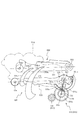
図3に示すように、パチンコ機10の背面側には、制御基板ユニット90,91と、裏パックユニット94とが主に備えられている。制御基板ユニット90は、主基板(主制御装置110)と音声ランプ制御基板(音声ランプ制御装置113)と表示制御基板(表示制御装置114)とが搭載されてユニット化されている。制御基板ユニット91は、払出制御基板(払出制御装置111)と発射制御基板(発射制御装置112)と電源基板(電源装置115)とカードユニット接続基板116とが搭載されてユニット化されている。
As shown in FIG. 3, on the back side of the
裏パックユニット94は、保護カバー部を形成する裏パック92と払出ユニット93とがユニット化されている。また、各制御基板には、各制御を司る1チップマイコンとしてのMPU、各種機器との連絡をとるポート、各種抽選の際に用いられる乱数発生器、時間計数や同期を図る場合などに使用されるクロックパルス発生回路等が、必要に応じて搭載されている。
In the
なお、主制御装置110、音声ランプ制御装置113及び表示制御装置114、払出制御装置111及び発射制御装置112、電源装置115、カードユニット接続基板116は、それぞれ基板ボックス100〜104に収納されている。基板ボックス100〜104は、ボックスベースと該ボックスベースの開口部を覆うボックスカバーとを備えており、そのボックスベースとボックスカバーとが互いに連結されて、各制御装置や各基板が収納される。
The
また、基板ボックス100(主制御装置110)及び基板ボックス102(払出制御装置111及び発射制御装置112)は、ボックスベースとボックスカバーとを封印ユニット(図示せず)によって開封不能に連結(かしめ構造による連結)している。また、ボックスベースとボックスカバーとの連結部には、ボックスベースとボックスカバーとに亘って封印シール(図示せず)が貼着されている。この封印シールは、脆性な素材で構成されており、基板ボックス100,102を開封するために封印シールを剥がそうとしたり、基板ボックス100,102を無理に開封しようとすると、ボックスベース側とボックスカバー側とに切断される。よって、封印ユニット又は封印シールを確認することで、基板ボックス100,102が開封されたかどうかを知ることができる。
Further, the substrate box 100 (main control device 110) and the substrate box 102 (dispensing
払出ユニット93は、裏パックユニット94の最上部に位置して上方に開口したタンク130と、タンク130の下方に連結され下流側に向けて緩やかに傾斜するタンクレール131と、タンクレール131の下流側に縦向きに連結されるケースレール132と、ケースレール132の最下流部に設けられ、払出モータ216(図4参照)の所定の電気的構成により球の払出を行う払出装置133とを備えている。タンク130には、遊技ホールの島設備から供給される球が逐次補給され、払出装置133により必要個数の球の払い出しが適宜行われる。タンクレール131には、当該タンクレール131に振動を付加するためのバイブレータ134が取り付けられている。
The dispensing
また、払出制御装置111には状態復帰スイッチ120が設けられ、発射制御装置112には可変抵抗器の操作つまみ121が設けられ、電源装置115にはRAM消去スイッチ122が設けられている。状態復帰スイッチ120は、例えば、払出モータ216(図4参照)部の球詰まり等、払出エラーの発生時に球詰まりを解消(正常状態への復帰)するために操作される。操作つまみ121は、発射ソレノイドの発射力を調整するために操作される。RAM消去スイッチ122は、パチンコ機10を初期状態に戻したい場合に電源投入時に操作される。
Further, the
次に、図4を参照して、本パチンコ機10の電気的構成について説明する。図4は、パチンコ機10の電気的構成を示すブロック図である。
Next, an electrical configuration of the
主制御装置110には、演算装置である1チップマイコンとしてのMPU201が搭載されている。MPU201には、該MPU201により実行される各種の制御プログラムや固定値データを記憶したROM202と、そのROM202内に記憶される制御プログラムの実行に際して各種のデータ等を一時的に記憶するためのメモリであるRAM203と、そのほか、割込回路やタイマ回路、データ送受信回路などの各種回路が内蔵されている。主制御装置110では、MPU201によって、大当たり抽選や第1図柄表示装置37A,37B及び第3図柄表示装置81における表示の設定、第2図柄表示装置における表示結果の抽選といったパチンコ機10の主要な処理を実行する。
The
なお、払出制御装置111や音声ランプ制御装置113などのサブ制御装置に対して動作を指示するために、主制御装置110から該サブ制御装置へ各種のコマンドがデータ送受信回路によって送信されるが、かかるコマンドは、主制御装置110からサブ制御装置へ一方向にのみ送信される。
Various commands are transmitted from the
RAM203は、各種エリア、カウンタ、フラグのほか、MPU201の内部レジスタの内容やMPU201により実行される制御プログラムの戻り先番地などが記憶されるスタックエリアと、各種のフラグおよびカウンタ、I/O等の値が記憶される作業エリア(作業領域)とを有している。なお、RAM203は、パチンコ機10の電源の遮断後においても電源装置115からバックアップ電圧が供給されてデータを保持(バックアップ)できる構成となっており、RAM203に記憶されるデータは、すべてバックアップされる。
The
停電などの発生により電源が遮断されると、その電源遮断時(停電発生時を含む。以下同様)のスタックポインタや、各レジスタの値がRAM203に記憶される。一方、電源投入時(停電解消による電源投入を含む。以下同様)には、RAM203に記憶される情報に基づいて、パチンコ機10の状態が電源遮断前の状態に復帰される。RAM203への書き込みはメイン処理(図示せず)によって電源遮断時に実行され、RAM203に書き込まれた各値の復帰は電源投入時の立ち上げ処理(図示せず)において実行される。なお、MPU201のNMI端子(ノンマスカブル割込端子)には、停電等の発生による電源遮断時に、停電監視回路252からの停電信号SG1が入力されるように構成されており、その停電信号SG1がMPU201へ入力されると、停電時処理としてのNMI割込処理(図示せず)が即座に実行される。
When the power is cut off due to the occurrence of a power failure or the like, the stack pointer and the value of each register when the power is cut off (including when a power failure occurs; the same applies hereinafter) are stored in the
主制御装置110のMPU201には、アドレスバス及びデータバスで構成されるバスライン204を介して入出力ポート205が接続されている。入出力ポート205には、払出制御装置111、音声ランプ制御装置113、第1図柄表示装置37A,37B、第2図柄表示装置、第2図柄保留ランプ、特定入賞口65aの開閉板の下辺を軸として正面側に開閉駆動するための大開放口ソレノイドや電動役物を駆動するためのソレノイドなどからなるソレノイド209が接続され、MPU201は、入出力ポート205を介してこれらに対し各種コマンドや制御信号を送信する。
An input /
また、入出力ポート205には、図示しないスイッチ群およびスライド位置検出センサSや回転位置検出センサRを含むセンサ群などからなる各種スイッチ208、電源装置115に設けられた後述のRAM消去スイッチ回路253が接続され、MPU201は各種スイッチ208から出力される信号や、RAM消去スイッチ回路253より出力されるRAM消去信号SG2に基づいて各種処理を実行する。
The input /
払出制御装置111は、払出モータ216を駆動させて賞球や貸出球の払出制御を行うものである。演算装置であるMPU211は、そのMPU211により実行される制御プログラムや固定値データ等を記憶したROM212と、ワークメモリ等として使用されるRAM213とを有している。
The
払出制御装置111のRAM213は、主制御装置110のRAM203と同様に、MPU211の内部レジスタの内容やMPU211により実行される制御プログラムの戻り先番地などが記憶されるスタックエリアと、各種のフラグおよびカウンタ、I/O等の値が記憶される作業エリア(作業領域)とを有している。RAM213は、パチンコ機10の電源の遮断後においても電源装置115からバックアップ電圧が供給されてデータを保持(バックアップ)できる構成となっており、RAM213に記憶されるデータは、すべてバックアップされる。なお、主制御装置110のMPU201と同様、MPU211のNMI端子にも、停電等の発生による電源遮断時に停電監視回路252から停電信号SG1が入力されるように構成されており、その停電信号SG1がMPU211へ入力されると、停電時処理としてのNMI割込処理(図示せず)が即座に実行される。
Like the
払出制御装置111のMPU211には、アドレスバス及びデータバスで構成されるバスライン214を介して入出力ポート215が接続されている。入出力ポート215には、主制御装置110や払出モータ216、発射制御装置112などがそれぞれ接続されている。また、図示はしないが、払出制御装置111には、払い出された賞球を検出するための賞球検出スイッチが接続されている。なお、該賞球検出スイッチは、払出制御装置111に接続されるが、主制御装置110には接続されていない。
An input /
発射制御装置112は、主制御装置110により球の発射の指示がなされた場合に、操作ハンドル51の回動操作量に応じた球の打ち出し強さとなるよう球発射ユニット112aを制御するものである。球発射ユニット112aは、図示しない発射ソレノイドおよび電磁石を備えており、その発射ソレノイドおよび電磁石は、所定条件が整っている場合に駆動が許可される。具体的には、遊技者が操作ハンドル51に触れていることをタッチセンサ51aにより検出し、球の発射を停止させるための発射停止スイッチ51bがオフ(操作されていないこと)を条件に、操作ハンドル51の回動操作量(回動位置)に対応して発射ソレノイドが励磁され、操作ハンドル51の操作量に応じた強さで球が発射される。
The
音声ランプ制御装置113は、音声出力装置(図示しないスピーカなど)226における音声の出力、ランプ表示装置(電飾部29〜33、表示ランプ34など)227における点灯および消灯の出力、変動演出(変動表示)や予告演出といった表示制御装置114で行われる第3図柄表示装置81の表示態様の設定などを制御するものである。演算装置であるMPU221は、そのMPU221により実行される制御プログラムや固定値データ等を記憶したROM222と、ワークメモリ等として使用されるRAM223とを有している。
The sound
音声ランプ制御装置113のMPU221には、アドレスバス及びデータバスで構成されるバスライン224を介して入出力ポート225が接続されている。入出力ポート225には、主制御装置110、表示制御装置114、音声出力装置226、ランプ表示装置227、その他装置228、枠ボタン22などがそれぞれ接続されている。その他装置228には駆動モータ433,462,551及びソレノイド474が含まれる。
The input /
音声ランプ制御装置113は、主制御装置110から受信した各種のコマンド(変動パターンコマンド、停止種別コマンド等)に基づいて、第3図柄表示装置81の表示態様を決定し、決定した表示態様をコマンド(表示用変動パターンコマンド、表示用停止種別コマンド等)によって表示制御装置114へ通知する。また、音声ランプ制御装置113は、枠ボタン22からの入力を監視し、遊技者によって枠ボタン22が操作された場合は、第3図柄表示装置81で表示されるステージを変更したり、スーパーリーチ時の演出内容を変更したりするように、表示制御装置114へ指示する。ステージが変更される場合は、変更後のステージに応じた背面画像を第3図柄表示装置81に表示させるべく、変更後のステージに関する情報を含めた背面画像変更コマンドを表示制御装置114へ送信する。ここで、背面画像とは、第3図柄表示装置81に表示させる主要な画像である第3図柄の背面側に表示される画像のことである。表示制御装置114は、この音声ランプ制御装置113から送信されるコマンドに従って、第3図柄表示装置81に各種の画像を表示する。
The voice
また、音声ランプ制御装置113は、表示制御装置114から第3図柄表示装置81の表示内容を表すコマンド(表示コマンド)を受信する。音声ランプ制御装置113では、表示制御装置114から受信した表示コマンドに基づき、第3図柄表示装置81の表示内容に合わせて、その表示内容に対応する音声を音声出力装置226から出力し、また、その表示内容に対応させてランプ表示装置227の点灯および消灯を制御する。
Further, the sound
表示制御装置114は、音声ランプ制御装置113及び第3図柄表示装置81が接続され、音声ランプ制御装置113より受信したコマンドに基づいて、第3図柄表示装置81における第3図柄の変動演出などの表示を制御するものである。また、表示制御装置114は、第3図柄表示装置81の表示内容を通知する表示コマンドを適宜音声ランプ制御装置113へ送信する。音声ランプ制御装置113は、この表示コマンドによって示される表示内容にあわせて音声出力装置226から音声を出力することで、第3図柄表示装置81の表示と音声出力装置226からの音声出力とをあわせることができる。
The
電源装置115は、パチンコ機10の各部に電源を供給するための電源部251と、停電等による電源遮断を監視する停電監視回路252と、RAM消去スイッチ122(図3参照)が設けられたRAM消去スイッチ回路253とを有している。電源部251は、図示しない電源経路を通じて、各制御装置110〜114等に対して各々に必要な動作電圧を供給する装置である。その概要としては、電源部251は、外部より供給される交流24ボルトの電圧を取り込み、各種スイッチ208などの各種スイッチや、ソレノイド209などのソレノイド、モータ等を駆動するための12ボルトの電圧、ロジック用の5ボルトの電圧、RAMバックアップ用のバックアップ電圧などを生成し、これら12ボルトの電圧、5ボルトの電圧及びバックアップ電圧を各制御装置110〜114等に対して必要な電圧を供給する。
The
停電監視回路252は、停電等の発生による電源遮断時に、主制御装置110のMPU201及び払出制御装置111のMPU211の各NMI端子へ停電信号SG1を出力するための回路である。停電監視回路252は、電源部251から出力される最大電圧である直流安定24ボルトの電圧を監視し、この電圧が22ボルト未満になった場合に停電(電源断、電源遮断)の発生と判断して、停電信号SG1を主制御装置110及び払出制御装置111へ出力する。停電信号SG1の出力によって、主制御装置110及び払出制御装置111は、停電の発生を認識し、NMI割込処理を実行する。なお、電源部251は、直流安定24ボルトの電圧が22ボルト未満になった後においても、NMI割込処理の実行に充分な時間の間、制御系の駆動電圧である5ボルトの電圧の出力を正常値に維持するように構成されている。よって、主制御装置110及び払出制御装置111は、NMI割込処理(図示せず)を正常に実行し完了することができる。
The power failure monitoring circuit 252 is a circuit for outputting a power failure signal SG1 to each NMI terminal of the
RAM消去スイッチ回路253は、RAM消去スイッチ122(図3参照)が押下された場合に、主制御装置110へ、バックアップデータをクリアさせるためのRAM消去信号SG2を出力するための回路である。主制御装置110は、パチンコ機10の電源投入時に、RAM消去信号SG2を入力した場合に、バックアップデータをクリアすると共に、払出制御装置111においてバックアップデータをクリアさせるための払出初期化コマンドを払出制御装置111に対して送信する。
The RAM
次いで、図5から図9を参照して、遊技盤13及び動作ユニット200について説明する。まず、図5及び図6を参照して、背面ケース210への各ユニット400及び500の収容構造について説明する。
Next, the
図5は、動作ユニット200の正面斜視図であり、図6は、分解した動作ユニット200を正面視した動作ユニット200の分解正面斜視図である。
FIG. 5 is a front perspective view of the
図5及び図6に示すように、動作ユニット200は、底壁部211と、その底壁部211の外縁から立設される外壁部212とから一面側(図6紙面手前側)が開放された箱状に形成される背面ケース210を備える。背面ケース210は、その底壁部211の中央に矩形状の開口211aが開口形成されることで、正面視矩形の枠状に形成される。開口211aは、第3図柄表示装置81(図2参照)の外形に対応した(即ち、第3図柄表示装置81を配設可能な)大きさに形成される。
As shown in FIGS. 5 and 6, the
左右および上部の外壁部212は、前後方向の中間に底壁部211と平行に形成される中間壁部212aと、その中間壁部212aに部材を締結可能な締結部212bと、を備える。その中間壁部212aの手前側においては、外壁部212は中間壁部212aの開口211aの反対側の端部から延設され、中間壁部212aの奥側においては、外壁部212は中間壁部212aの開口211aに近接する側の端部から延設される。
The left, right, and upper
なお、左右の中間壁部212aに形成される締結部212bには、保持固定部446や固定板461が締結固定され、上部の中間壁部212aに形成される締結部212bには、案内板424が締結固定される。
The holding and fixing
ここで、固定板461は複合動作ユニット400を駆動させる駆動力を発生させる駆動モータ462を支持する部材であり、保持固定部446は付勢バネ445の一端を固定する部材であり、案内板424は複合動作ユニット400の連結部材423(図20参照)の移動を案内する部材である。即ち、いずれも、遊技者に直接視認される演出部分ではなく、複合動作ユニット400の動作の駆動力を発生させたり、その動作を案内したりする、演出の補助的な役割を備える部分である。
Here, the fixing
このような役割を備える固定板461や、保持固定部446や、案内板424を背面ケース210の前側寄りに配置することで、背面ケース210の後ろ側寄りのスペースを空けることができる。この空いた後ろ側寄りのスペースを遮蔽部材420等の実際に遊技者に視認される部分を退避させるスペースとして用いることで、複合動作ユニット400の構成部材を前後で積層させることができ、開口211aの外側に複合動作ユニット400を退避させるために必要となる幅を狭くすることができる。従って、底板部211の形成幅を狭めることができる。これにより、開口211aを拡大することができ、第3図柄表示装置81の形成範囲を拡大することができる。
By arranging the fixing
動作ユニット200は、背面ケース210の内部空間に、複合動作ユニット400及び揺動動作ユニット500がそれぞれ収容され、これを1ユニットとして構成される。
In the
具体的には、複合動作ユニット400は、背面ケース210の外壁部212の内側面が形成する領域の左右および上部に配設され、揺動動作ユニット500は、背面ケース210の外壁部212の内側面が形成する領域の下部に配設される(図5参照)。
Specifically, the
次いで、図7から図9を参照して、複合動作ユニット400及び揺動動作ユニット500の動作態様の概略について説明する。なお、図7から図9の説明においては、図5及び図6を適宜参照する。
Next, with reference to FIGS. 7 to 9, an outline of operation modes of the
図7から図9は、動作ユニット200の正面図である。なお、図7では複合動作ユニット400の本体部材410が張出位置に配置された状態が、図8では揺動動作ユニット500の移動部材540が張出位置に配置された状態が、図9では複合動作ユニット400の本体部材410及び揺動動作ユニット500の移動部材540が張出位置に配置された状態がそれぞれ図示される。
7 to 9 are front views of the
図7に示すように、複合動作ユニット400は、本体部材410を、図5に示す退避位置と図7に示す張出位置との間で動作させる。即ち、図5に示す退避位置では、本体部材410は、背面ケース210の開口211aの上方に退避される(図2参照)。一方、図7に示す張出位置では、本体部材410が下降され、本体部材410が背面ケース210の開口211aの中央(即ち、第3図柄表示装置81の正面、図2参照)に配置される。複合動作ユニット400は、後述するように、本体部材410がスライド移動することで遮蔽部材420が移動態様の違う2種類の動作(スライド動作、揺動動作)をするユニットである。
As shown in FIG. 7, the combined
図8に示すように、揺動動作ユニット500は、移動部材540を、図5に示す退避位置と図8に示す張出位置との間で動作させる。図5に示す退避位置では、移動部材540は、背面ケース210の開口211aの下方に退避される(図2参照)。一方、図8に示す張出位置では、移動部材540が上昇され、移動部材540が背面ケース210の開口211aの中央(即ち、第3図柄表示装置81の正面、図2参照)に配置される。移動部材540は左右一対で形成され、図8に示す張出位置では、左右一対の移動部材540が合体して視認される。
As shown in FIG. 8, the
図9に示すように、複合動作ユニット400及び揺動動作ユニット500は、共に張出位置に配置することができる。この場合、複合動作ユニット400及び揺動動作ユニット500を一体の装飾部材として視認させる(正面視で部分的に重ねる)ことができ、開口211aの外方の幅以上の幅の装飾部材を形成することができる。これにより、複合動作ユニット400及び揺動動作ユニット500の演出効果を向上させることができる。また、複合動作ユニット400及び揺動動作ユニット500が違う向き(下降、上昇)で開口211aの中央へ向けて張り出すことで、例えば可動部材を全て同じ向きで張り出させる場合に比較して、退避位置から張出位置まで各部材が移動する距離を短くすることができる。これにより、複合動作ユニット400及び揺動動作ユニット500の移動速度が同じ場合に、退避位置から張出位置まで移動する期間を短縮することができる。
As shown in FIG. 9, both the
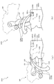
次いで、図10から図18を参照して、遊技盤13の下部に配設される盤面下部ユニット300について説明する。図10及び図11は、遊技盤13及び盤面下部ユニット300の正面分解斜視図であり、図12は、遊技盤13及び盤面下部ユニット300の背面分解斜視図である。なお、図10では、前板部材320のみが遊技版13から分解された状態が図示され、図11及び図12では、図10から更に盤面下部ユニット300の前側ユニット310及び可変入賞装置330が遊技盤13から分解される。また、理解を容易にするために、遊技盤13は簡略化して図示される。
Next, with reference to FIG. 10 to FIG. 18, the board
図10に示すように、内レール61の下縁に沿って特定入賞口65aが形成される。内レール61の下縁は下に凸の曲線形状から形成されるので、特定入賞口65aの下辺が左右方向に沿う直線で形成される場合に比較して、特定入賞口65aの配設位置を下方に下げることができる。この特定入賞口65aの外縁は、上辺が移動上蓋部材332で形成され、下辺が内レール61の下縁で形成されると共に、左右の辺が開口上側部313の左右の壁部で形成される。
As shown in FIG. 10, a specific winning
特定入賞口65aは、後述するように、移動上蓋部材332が前後にスライド移動することで、上述した閉鎖状態と開放状態とが切り替えられ、この特定入賞口65aの開閉動作は、最高で例えば15回(15ラウンド)繰り返し可能にされている。
As will be described later, the specific winning
図11に示すように、盤面下部ユニット300は、球が排出されるアウト口314と、特定入賞口65aとを構成するユニットであって、遊技盤13の下部に前後方向に穿設される受け入れ開口60aに正面側から嵌め込まれ締結固定される前側ユニット310と、その前側ユニット310に正面側から締結固定されると共に背面側に球の経路が形成される前板部材320と、受け入れ開口60aに背面側から嵌め込まれ締結固定されると共に球の流下方向を変化させる移動上蓋部材332を備える可変入賞装置330と、を主に備える。
As shown in FIG. 11, the
前側ユニット310は、正面側を球が流下可能に形成される板状の本体板部311と、その本体板部311の正面側中央で一対の部材が左右に開閉動作される電動役物640aと、本体板部311の左右上部において正面側に突設される板状の傾斜板部312と、本体板部311の下底部から上方へ向けて凹設される開口上側部313と、その開口上側部313の左右両側において前後方向に穿設され球が遊技領域外に排出される一対のアウト口314と、を主に備える。
The
本体板部311は、電動役物640aの上方に形成され第1入賞口64の下辺を形成する第1入賞口下辺311aと、電動役物640aの一対の部材に囲われる位置において前後方向に穿設される第2入賞口640と、その第2入賞口640の下方に配置され第2入賞口640の正面側を照らす光照射装置311bと、アウト口314の外側においてリブ状に正面側へ向けて凸設される球流しリブ311cと、を主に備える。
The main
光照射装置311bは、前板部材320の収容凹部323a(図12参照)に収容され、第2入賞口640に球が入賞することに起因して、上方(第2入賞口640側)へ向けて光が照射されるLED部材である。
The
球流しリブ311cは、内レール61に沿って転動する球の流下方向を調整するものであり、詳細は図18で後述する。
The
傾斜板部312は、上側面を球が転動可能に形成され、電動役物640aの左右上方に配置されると共に、電動役物640aへ近接されるほど下降傾斜される。これにより、電動役物640aが左右に倒れる開状態の時は、傾斜板部312を転動して流下される球を高確率で第2入賞口640へ入賞させることができる。一方、電動役物640aが起立される閉状態の時は、傾斜板部312を転動して流下される球を高確率で開口上側部313の正面側へ落下させることができる。
The
開口上側部313は、左右中央へ向かうにつれて上昇傾斜して形成される。ここで、特定入賞口65aの左右方向中央部の上下幅を球の直径以上とすることで、開口上側部313の左右の壁部の上下幅(特定入賞口65aの左右の壁部に対応する)を球の直径以下の長さに設定することが可能である(図17参照)。この場合、特定入賞口65aの左右端部から球を入賞させることは困難であるが、球が内レール61に沿って遊技盤13の中央部へ流下され、特定入賞口65aの左右方向中央部から入賞可能とされるので、遊技を継続できる。
The
ここで、特定入賞口65aの上下側面が平行面(左右方向へ延設される平面)である場合、内レール61と交差する直線が特定入賞口65aの下側面の長さと同じになるまで、特定入賞口65aを内レール61の下縁から上昇させて配置する必要がある。そのため、特定入賞口65aの位置が高くなる。
Here, when the upper and lower side surfaces of the specific winning
一方、本実施形態では、特定入賞口65aの下側側面が内レール61の下側面と同様に湾曲形成されるので、特定入賞口65aを上昇配置させる必要がなく、特定入賞口65aを低位置に配置することができる。
On the other hand, in the present embodiment, since the lower side surface of the specific winning
また、特定入賞口65aの上側側面が左右端部へ近接するにつれて下降傾斜されるので、上側側面が左右方向へ延設される平面で形成される場合に比較して、特定入賞口65aへ球を案内する道釘の配置を下方へ下げることができる。これにより、第3図柄表示装置81の下縁を下げることができる。
Further, since the upper side surface of the specific winning
アウト口314は、開口上側部313の左右に一対で形成され、開口上側部313の左右端部に対して、アウト口314の下辺は下方に配置され、アウト口314の上辺は上方に配置される。即ち、開口上側部313がアウト口314よりも下方に形成される。これにより、後述する可変入賞装置330の配置を下方へ下げることができ、第3図柄表示装置81の下縁を下げることができる。なお、このような配置であっても、本実施形態では開口上側部313の形状と略同一形状の上側面を備え前後方向にスライド移動される移動上蓋部材332の上面を球が流下され、球がアウト口314へ排出されるので(図17参照)、遊技が継続可能となる。
The out
前板部材320は、光透過性の樹脂材料から形成される板状部材であって、前側ユニット310の正面側に配設されると共に本体板部311との間を球が流下可能に形成される板状の本体板部321と、その本体板部321の上端部に配設され第1入賞口下辺311aへ球を案内する第1入賞口前部322と、電動役物640aの下方に配置される電動役物下支え部323と、アウト口314の下側面に沿って配置されるアウト口下板324と、内レール61の下縁に沿って本体板部321から背面側に突設される球送り部325と、を主に備える。
The
本体板部321は、アウト口下板324の外側において、背面側にリブ状に凸設される球流しリブ321aを備える。球流しリブ321aは、内レール61に沿って転動する球の流下方向を調整するものであるが、その詳細については図18で後述する。
The main
電動役物下支え部323は、横長の凹部である収容凹部323aを備え、その収容凹部323aには、光照射装置311bが収容される。
The electric accessory
アウト口下板324は、上側面に前後方向に延設される細厚のリブが左右方向に連設される。また、アウト口下板324は、左右内側端部に上方へ向けて突設される段部324aを備える。アウト口下板324の上側側面に形成される凸凹により、流下してきた球を減速させることができる。また、アウト口下板324に形成されるリブは、背面側へ向かうほど下降傾斜して形成される。これにより、流下してきた球をアウト口314へ排出する速度を向上させることができる。
The outer mouth
なお、上述した傾斜板部312がアウト口下板324の真上に形成される(図17参照)ので、傾斜板部312を転動してから落下する球がアウト口下板324へ向けて落下することが抑制される。即ち、傾斜板部312を転動してから落下する球は、一対のアウト口下板324の左右方向内側(移動上蓋部材332が配置される位置)に落下するか、アウト口下板324の外側端部(球流しリブ321a付近であって、リブの形成範囲と球が流れるレールとの境界位置)に落下するかのどちらかである。これらは、どちらもリブの形成範囲外である。これにより、アウト口下板324に高所から球が落下することを抑制することができ、アウト口下板324の耐久性を向上させることができる。
Since the above-mentioned
段部324aは、アウト口314と特定入賞口65aとの間に形成される段であって、左右方向から流下してアウト口下板324の上側側面を流下する球は、段部324aを越えて左右方向中央部へ流下されることが防止される(図17参照)。即ち、左右方向から流下してアウト口下板324の上側側面を流下する球は、専らアウト口314へ案内される。
The
球送り部325は、背面側に形成される背面側側面325aと、その背面側側面325aと連結されると共に左右側に形成される左右側側面325bと、を主に備える。
The
背面側側面325aは、背面側へ向かうにつれて下降傾斜され、左右側側面325bは、背面側へ向かうにつれて中央へ向けて傾斜される。これにより、球送り部325に到達した球の流下方向を背面側へ向けることができる。従って、特定入賞口65aの手前で球が留まることを抑制し、所謂オーバー入賞を防止することができる。
The
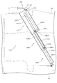
次いで、図13から図15を参照して、可変入賞装置330について説明する。図13は、可変入賞装置330の正面分解斜視図であり、図14は、可変入賞装置330の背面分解斜視図であり、図15(a)は、可変入賞装置330の上面図であり、図15(b)は可変入賞装置330の正面図であり、図15(c)は、図15(b)の矢印XVc方向視における可変入賞装置330の側面図である。
Next, the
図13及び図14に示すように、可変入賞装置330は、骨格を形成する本体部材331と、その本体部材331に前方から挿通され、前後方向へスライド移動可能に形成される移動上蓋部材332と、その移動上蓋部材332をスライド移動させる駆動力を発生させるソレノイド333と、そのソレノイド333により揺動されるレバー部材334bが収容されると共に本体部材331の背面側に締結固定される後蓋部材334と、を主に備える。
As shown in FIGS. 13 and 14, the
本体部材331は、移動上蓋部材332が挿通される異形貫通孔331aと、特定入賞口65aに入賞された球が流下される下方通路331bと、その下方通路331bの下方に配設され上方へ向けて光を照射する光照射装置331cと、背面側に正面側へ向けて凹んで形成される窪みであってソレノイド333及びレバー部材334b等が収容される背面側収容部331dと、を主に備える。
The
異形貫通孔331aは、図15(a)及び図15(b)に図示されるように、移動上蓋部材332の形状に沿って形成される貫通孔であって、前側板部332aを収容する前方開口部331a1と、後側板部332bを収容する後方開口部331a2と、を主に備える。
As shown in FIGS. 15A and 15B, the deformed through-
前方開口部331a1は、正面視において下辺が水平に延設され、上辺が中心へ向かうにつれて上昇傾斜されると共に左右の側辺は上下に延設される五角形状に形成される窪みである。 The front opening 331a1 is a pentagon-shaped dent having a lower side extending horizontally in a front view, being inclined upward as the upper side approaches the center, and having left and right sides extending vertically.
後方開口部331a2は、前方開口部331a1の背面側中央部から、前方開口部331a1の左右部分を切り落とした形状で穿設される開口である。即ち、後方開口部331a2の下辺および上辺の外形と、前方開口部331aの下辺および上辺の外形とは前後方向で段が形成されるものではなく、面位置で形成される。これにより、移動上蓋部材332をスムーズに案内することができる。
The rear opening 331a2 is an opening formed by cutting off the left and right portions of the front opening 331a1 from the center on the rear side of the front opening 331a1. That is, the outer shape of the lower side and the upper side of the rear opening 331a2 and the outer shape of the lower side and the upper side of the
下方通路331bは、球が通過可能に左右一対で形成されると共に(図18(a)参照)、内レール61の下縁よりも下方へ張り出して形成される通路であって、その奥に球の通過を検出するセンサSが配設される(図15(b)参照)。
The
光照射装置331cは、下方通路331bや板状部332a1等を光で照らして演出する装置であって、内レール61の下方(受け入れ開口60aの下部)に配設される。これにより、光照射装置331cに必要な装置等を内レール61の下方に配設することができるので、遊技盤13の背面側のスペースを確保することができ、第3図柄表示装置81(図2参照)の下縁を下方へ下げることができる。
The
なお、光照射装置331cは、光を照射する光照射部331c1を備える。その光照射部331c1は、下方通路331bの真下に左右一対で形成され、上方に光を照射する。
The
背面側収容部331dは、後方開口部331a2を挟んで前方開口部331a1と連通されている。
The back
移動上蓋部材332は、光透過性の樹脂材料から形成される長尺部材であって、前方開口部331a1に収容される前側板部332aと、後方開口部331a2に収容される後側板部332bと、前側板部332a及び後側板部332bの中心軸に沿って下方へ突設される中心リブ332cと、後側板部332bの背面側端部に上下方向に穿設される連結孔332dと、を主に備える。
The moving
前側板部332aは、前方開口部331a1の上辺の形状に沿って左右方向中央部へ向けて上昇傾斜する態様で形成される板状部332a1と、その板状部332a1の上下方向に穿設される肉抜き孔332a2と、板状部332a1の左右方向端部において下方へ向けて張り出され前後方向へ向けて延設される案内リブ332a3と、を主に備える。
The front-
板状部332a1は、下方へ向かうほど背面側へ傾斜して形成されると共に(図16参照)左右方向中央部へ向かうほど背面側へ凹んで形成される前側傾斜側面332a1fを備える。前側傾斜側面332a1fが左右方向中央部へ向かうほど背面側へ凹んで形成されることにより、球が前板部材320と前側傾斜側面332a1fとに挟まれた場合に球を中央側へ流すことができ、球により移動上蓋部材332のスライド動作が妨害されることを防止できる。
The plate-shaped portion 332a1 includes a front inclined side surface 332a1f which is formed so as to be inclined toward the rear side as it goes downward (see FIG. 16) and is depressed toward the rear side as it goes toward the center in the left-right direction. Since the front inclined side surface 332a1f is formed so as to be concave toward the rear side toward the center in the left-right direction, the ball can flow toward the center when the ball is sandwiched between the
なお、前側傾斜側面332a1fは後述するように光を反射させる部分として形成されるので、光を効果的に反射させるために、前側傾斜側面332a1fに金属膜を形成するようにしたり、鏡面加工したりしても良い。本実施形態では、光を反射するテープが貼付けられる。 Since the front inclined side surface 332a1f is formed as a portion for reflecting light as described later, in order to effectively reflect light, a metal film is formed on the front inclined side surface 332a1f or mirror-finished. You may. In this embodiment, a tape that reflects light is attached.
案内リブ332a3は、組立状態(図15参照)において、前方開口部331a1の左右側側面に沿って形成され、前方開口部331a1の下側側面と当接される。これにより、移動上蓋部材332のスライド移動時の左右方向の位置ずれを抑制することができる。
The guide rib 332a3 is formed along the left and right side surfaces of the front opening 331a1 in the assembled state (see FIG. 15), and is in contact with the lower side surface of the front opening 331a1. Accordingly, it is possible to suppress the displacement of the movable
中心リブ332cは、板形状が屈曲されて形成される前側板部332aの屈曲部に形成される。これにより、前側板部332aの剛性を向上させることができる。また、移動上蓋部材332が前方へスライド移動される場合(可変入賞装置330の移動上蓋部材332が退避状態とされる場合)に、開口上側部313の背面側に留められる。これにより、中心リブ332cと球とが衝突して移動上蓋部材332が動作不良を起こすことを防止することができる。
The
連結孔332dは、レバー部材334bの連結部334b4が挿通され、レバー部材334bの揺動による変位が移動上蓋部材332に伝達される貫通孔である(図16参照)。
The
ソレノイド333は、駆動源となる本体部333aと、その本体部333aの下方に配設され、レバー部材334bの下方において上下に移動される鉤形の鉤形部材333bと、を主に備える。
The
後蓋部材334は、板状の本体部334aと、その本体部334aに揺動可能に軸支され先端が前後方向に移動可能に形成されるレバー部材334bと、を主に備える。
The
レバー部材334bは、上下方向に延設される本体部334b1と、その本体部334b1の下端部において左右両方向に円柱状に突設され本体部334aに軸支される一対の軸部334b2と、その一対の軸部334b2の略中間位置において本体部334b1の下方に延設され本体部334b1との間に鉤形部材333bを収容可能に形成される下爪部334b3と、本体部334b1の上端部において円柱状に膨出形成される連結部334b4と、を主に備える。
The
次いで、図16を参照して、移動上蓋部材332のスライド移動について説明する。図16(a)は、図15(b)のXVIa−XVIa線における可変入賞装置330の断面図であり、図16(b)は、図16(a)の状態から移動上蓋部材332をスライド移動させた後の可変入賞装置330の断面図である。なお、図16(a)では、移動上蓋部材332が後方配置される退避状態が図示され、図16(b)では、移動上蓋部材332が前方配置される張出状態が図示されると共に、光の経路E1について理解を容易にするために、中心リブ332cの図示が一部省略される。また、図16(a)及び図16(b)では、組立状態(図2参照)における内レール61及び前板部材320が仮想的に想像線で図示される。
Next, the sliding movement of the movable
図16(a)に示すように、移動上蓋部材332が退避状態を形成する場合、鉤形部材333bは上方へ配置され、レバー部材334bが後ろ倒れされる。この状態では、球は可変入賞装置330の前方を流下可能であり、即ち、球は特定入賞口65a(図10及び図17参照)に入賞可能(開放状態)とされる。
As shown in FIG. 16A, when the movable
一方、図16(b)に示すように、移動上蓋部材332が張出状態を形成する場合、鉤形部材333bが下方へ押し付けられることでレバー部材334bが軸部334b2を中心に前倒れされ背面側収容部331bの側面に当接されると共に移動上蓋部材332が正面側へスライド移動される。この状態では、球は特定入賞口65a(図10及び図17参照)に入賞不可能(閉鎖状態)とされる。
On the other hand, as shown in FIG. 16B, when the movable
この場合、鉤形部材333bの下方端部の背面側側面がレバー部材334bの下爪部334b3の端部と前後方向で当接されることで、レバー部材334bの揺動が機械的に規制される(下爪部334b3の移動方向に鉤形部材333bが配置されると共に下爪部334b3の移動方向と鉤形部材333bの移動方向とが直交する)。従って、ソレノイド333の駆動力によってレバー部材334bの揺動を停止させる場合に比較して、ソレノイド333の駆動力を抑制できる。
In this case, the back side surface of the lower end of the hook-shaped
ここで、図16を参照して、光照射装置331cから照射された光の経路について説明する。
Here, with reference to FIG. 16, a path of light emitted from the
図16(a)に示すように、移動上蓋部材332が退避状態とされる場合、光照射部331c1から上方に照射された光は経路E1に沿って板状部332a1の前側傾斜側面332a1fに到達する。このとき、前側傾斜側面332a1fが下方へ向かうほど背面側へ傾斜して形成されるので、下方から照射され前側傾斜側面332a1fに到達した光は前方(遊技者側)へ向けて反射される。この場合、移動上蓋部材332の前側傾斜側面332a1fが発光しているかのように遊技者に視認させることができる。また、前側傾斜側面332a1fで反射した光が前板部材320の投光範囲E0に投光されることから、前板部材320に注目させることができる。これにより、移動上蓋部材332及び前板部材320の演出能力を向上させることができる。
As shown in FIG. 16A, when the movable
ここで、移動上蓋部材332にLED等を配設して移動上蓋部材332を発光させる場合、移動上蓋部材332が大型化する恐れがある。一方、本実施形態では、移動上蓋部材332にLEDを配設することはしないので、移動上蓋部材332が大型化することを抑制しながら、移動上蓋部材332の演出部分としての能力を向上させることができる。
Here, when disposing an LED or the like on the movable
図16(b)に示すように、移動上蓋部材332が張出状態とされる場合、光照射部331c1から上方に経路E2に沿って照射され、前側傾斜側面332a1fに向かう光は、内レール61に遮蔽されることで板状部332a1の前側傾斜側面332a1fには到達しない。この場合、光照射部331c1から経路E1に沿って照射された光が、前側板部332aの板状部332a1の中間位置に到達し、そのまま透過するのみなので、前側傾斜側面332a1f及び前板部材320が遊技者に暗く視認される。
As shown in FIG. 16B, when the movable
即ち、移動上蓋部材332が退避状態とされるか、張出状態とされるかにより、前側傾斜側面332a1fに光照射部331c1から照射される光が到達するか否かが変化すると共に、前板部材320の投光範囲E0が明るく視認されるかが変化する。そのため、前側傾斜側面332a1fや前板部材320の投光範囲E0の明るさの状態を確認することで、特定入賞口65aに球を入賞可能か否か確認することができる。
That is, depending on whether the movable
従って、本実施形態のように、移動上蓋部材332が前後にスライド移動するために、移動上蓋部材332の状態の変化が正面視で把握しづらい場合でも(図17(a)及び図17(b)参照)、投光範囲E0の明るさの変化により特定入賞口65aに球を入賞可能か否か容易に確認することができる。
Therefore, even when the movable
ここで、移動上蓋部材332は、球の特定入賞口65aへの通過を妨げる閉鎖状態と、球の特定入賞口65aへの通過を可能とする開放状態と、を形成するために必要な動作(前後スライド移動)のみにより、投光範囲E0の明るさの状態を変化させている。換言すれば、遊技を継続するために移動上蓋部材332に必要とされる動作のみにより投光範囲E0の状態を変化させるので、追加の機構が必要とならない。即ち、移動上蓋部材332を、球の特定入賞口65aへの通過の可否を切り替える目的と、光照射部331c1から照射される光により演出を行う目的とで兼用することができる。
Here, the movable
なお、球が下方通路331bを通過する際に経路E1を横切ることで、光照射部331cから照射された光を球で反射させて演出を行っても良い。この場合、正面視で内レール61付近(図16(a)及び図17(b)の投光範囲E0の下方)を明るく照らすことができる。
When the sphere passes through the
図17を参照して、移動上蓋部材332が張出状態を形成する場合と、退避状態を形成する場合との球の流下について説明する。図17(a)及び図17(b)は、遊技盤13の部分正面図である。なお、図17(a)では、移動上蓋部材332が張出状態を形成する場合(図16(b)参照)が図示され、図17(b)では、移動上蓋部材332が退避状態(図16(a)参照)を形成する場合が図示され、図17(a)及び図17(b)において、前板部材320の本体板部321が想像線で図示される。なお、図17(a)及び図17(b)では、移動上蓋部材332が張出しているかどうかが網掛けの有無で図示される。即ち、図17(a)及び図17(b)において網掛けが形成される部分は、前板部材320に当接しているか又は前板部材320との間で球の通過を遮る程に前板部材320に近接している部分である。
With reference to FIG. 17, a description will be given of the flow of the ball when the movable
図17(a)に示す状態では、経路C2で落下する球は移動上蓋部材332の上側面に沿って流下され、アウト口314に排出される。この場合、球の重みで移動上蓋部材332が下倒れする恐れがあり、それにより、移動上蓋部材332の左右端部が段部324aよりも下方へ移動されると、球をアウト口314へ排出できなくなり遊技に支障をきたす。
In the state shown in FIG. 17A, the sphere that falls on the route C2 flows down along the upper side surface of the movable
これに対し、本実施形態では、移動上蓋部材332は、異形貫通孔331aの正面側に張り出される長さの数倍の長さ(約4倍の長さ、図16(b)参照)で異形貫通孔331aに収容されると共に可変入賞装置330の前後方向に亘って異形貫通孔331aの側面と上下方向で当接可能に形成される。そのため、移動上蓋部材332と異形貫通孔331aとのクリアランスを小さくすることで、移動上蓋部材332に衝突される球の重みにより移動上蓋部材332が下倒れすることを抑制することができる。これにより、移動上蓋部材332の左右両端部を段部324aと面位置に形成することができ、特定入賞口65aへの道釘を下方へ下げることができるので、第3図柄表示装置81の下縁を下方へ下げることができる。
On the other hand, in the present embodiment, the movable
図17(b)に示すように、移動上蓋部材332が退避状態を形成する場合において、球は、特定入賞口65aへ向けて流下することが可能となる。このとき、内レール61に沿って左右から経路C1で転動する球は段部324aに衝突し、アウト口314へ排出されるため、特定入賞口65aへ向けて上方から経路C2で落下する球が内レール61を転動し、特定入賞口65aに到達する。
As shown in FIG. 17 (b), when the movable
ここで、本実施形態では、特定入賞口65aの左右端部の上下幅が球の直径以下に形成される。即ち、移動上蓋部材332の左右端部における内レール61からの上下方向の距離が球の直径以下に形成される。そのため、段部324aの内レール61からの高さを低くすることができ、その段部324aから落下する球が到達するアウト口314の配置も低くすることができる。
Here, in the present embodiment, the vertical width of the left and right ends of the specific winning
また、この場合、球は特定入賞口65aの左右端部から入球することが困難となる(加えて、本実施形態では、ベース板60に球の入球が遮られる)。しかし、特定入賞口65aの下辺が内レール61に沿って形成されるので、特定入賞口65aの左右端部の正面側に流下した球は重力で内レール61に沿って遊技領域中央方向へ転動され、そこから特定入賞口65aへ入球する。なお、内レール61の下縁は後方に傾斜して形成されるので(図16参照)、球を特定入賞口65a(図17参照)にスムーズに入球させることができる。
In this case, it is difficult for the ball to enter from the left and right ends of the specific winning
これにより、特定入賞口65aの上辺を形成する移動上蓋部材332は、少なくとも遊技領域の中央付近(内レール61が最も下方に配置される付近)において球の直径以上に内レール61から上方に離間すれば良いので、移動上蓋部材332の配設位置を下方へ下げることができる。従って、内レール61の中央付近以外の位置において球の直径以上に内レール61から上方に離間する必要がある場合に比較して、可変入賞装置330の配設位置を下方に下げることができる。これにより、遊技盤13の背面側のスペースを確保することができ、第3図柄表示装置81(図2参照)の下縁を下方へ下げることができる。
Thereby, the movable
次いで、図18を参照して、球流しリブ311c,321aや球送り部325の機能及び前側傾斜側面332a1fにより光が集光されることについて説明する。図18(a)は、図17(b)のXVIIIa−XVIIIa線における盤面下部ユニット300の断面図であり、図18(b)は、図17(a)のXVIIIb−XVIIIb線における盤面下部ユニット300の断面図であり、図18(c)は、図18(b)から光照射部331c1の配置を仮想的に変化させた盤面下部ユニット300の断面図である。
Next, with reference to FIG. 18, a description will be given of the function of the ball-flowing
なお、図18(a)では、球の転動経路が経路C1a,C1b,C2aで記載されると共に、退避状態とされた移動上蓋部材332が想像線で図示される。移動上蓋部材332は図18(a)の断面よりも手前側(図17(b)上側)にあり、実際は視認されるものではないが、説明の便宜のために、上下方向視(図18紙面垂直方向視)の位置が合致した状態で、図18(a)に想像線で図示される。また、図18(b)及び図18(c)では、下方通路331bを流下する球が仮想的に3個図示される。
In FIG. 18A, the rolling path of the ball is described by paths C1a, C1b, and C2a, and the movable
左右方向から内レール61(図11参照)に沿って転動され、アウト口314へ排出される球の経路について説明する。図18(a)に示すように、左右方向から図18(a)中央へ向けて転動する球は、球流しリブ311c又は球流しリブ321aの少なくとも一方に当接する。即ち、前側ユニット310の本体板部311に当接しながら転動する球は、球流しリブ311cに当接し、前板部材320の本体板部321に当接しながら転動する球は、球流しリブ321aに当接する。
The path of a sphere that is rolled from the left and right along the inner rail 61 (see FIG. 11) and discharged to the
ここで、球が球流しリブ311cに当接すると、経路C1aに沿った方向に球の速度方向が向き、次いで球流しリブ321aに当接する。そのため、球が前側ユニット310の本体板部311に当接しながら転動するか、前板部材320の本体板部321に当接しながら転動するかに関わらず、転動する球を球長しリブ321aに当接させることができる。
Here, when the sphere flows and abuts against the
内レール61(図11参照)に沿って転動する球を球流しリブ321aに当接させることで、球の速度方向を経路C1bに沿った方向に向けることができる。この場合、球がアウト口314の正面側に配置される前から球の速度を背面側(図18(a)上側)へ向けることができる。そのため、球がアウト口314の正面側に配置されてから球が遊技領域から排出されるまでの期間を短くすることができ、球がアウト口314の正面側に滞留することを抑制することができると共に、アウト口314の開口幅を抑制することができる。これにより、特定入賞口65a(図10参照)とアウト口314とが左右に並設される場合に、特定入賞口65aの配置を遊技領域の下方へ下げることができる。
By causing the ball rolling along the inner rail 61 (see FIG. 11) to flow into contact with the
球が左右一対で並列される段部324aの間に落下する場合について説明する。この場合、段部324aの間に落下した球は左右方向中央へ向けて転動し、球が球送り部325の左右側側面325bに当接することで、球の速度方向が経路C2aに沿って変化する。これにより、球が特定入賞口65a(図10参照)の正面側に滞留することを抑制することができるので、オーバー入賞を抑制することができる。
The case where the ball falls between the stepped
球が下方通路331bに沿って流下し、光照射部331c1から照射される光を横切る際には、その球が光を遮蔽することで、光は前側傾斜側面332a1fに到達しなくなる。そのため、前側傾斜側面332a1fや前板部材320の投光範囲E0が明るく視認されるか暗く視認されるかで球が特定入賞口65a(図17参照)に入賞したか否かを確認することができる。
When the sphere flows down along the
これにより、本実施形態のように、特定入賞口65aの前に光透過性の樹脂材料から形成される前板部材320が配設され、特定入賞口65aの内側が視認し難い場合であっても、投光範囲E0の明るさの変化により球が特定入賞口65aに入球したことを確認することができる。そのため、特定入賞口65aに球が入球することを確認するために特定入賞口65aを斜め上から除き込む必要が無く、遊技者の負担を緩和することができる。
Thus, as in the present embodiment, the
なお、本実施形態では、光照射部331c1から照射される光の照射方向と、下方通路331bを流下する球の流下方向とが、直角に近い角度で交差する(図18(b)参照)。そのため、球が光の進行方向に対向して流下する場合(図18(c)参照)や、球が光の照射方向に沿って流下する場合に比較して、特定入賞口65aに入球し下方通路331bを流下する球が光を遮蔽する期間を短くすることができる。換言すれば、前側傾斜側面332a1fや前板部材320の投光範囲E0が明るく視認される期間を長くすることができ、前側傾斜側面332a1fや前板部材320の演出能力を確保することができる。
In the present embodiment, the irradiation direction of the light irradiated from the light irradiation unit 331c1 and the flowing direction of the sphere flowing down the
図18(b)に示すように、光の経路E1と、下方通路331bを流下する球の流下方向とが直角に近い角度で交差する(横切る)場合、光の経路E1が球に遮られた後、球が下方通路331bの前端部(図18(b)右側)を通過する辺りで、光は球に遮られなくなる(光が前側傾斜側面332a1fに到達するようになる)。
As shown in FIG. 18B, when the light path E1 and the flowing direction of the sphere flowing down the
この場合、球が連なって下方通路331bを流下するとしても、1球ごとに経路E1を遮蔽することになるので、前側傾斜側面332a1fや前板部材320の投光範囲E0の明るさの変化を確認することにより、特定入賞口65aに入球した球の個数を確認することができる。
In this case, even if the balls continue to flow down the
一方、図18(c)に示すように、光の経路E3と、下方通路331bを流下する球の流下方向とが平行に近い関係である場合、光の経路E3が球に遮られた後、球が下方通路331bの後端部(図18(c)左側、センサS付近)に到達し下方へ落下することで、光は球に遮られなくなる(光が前側傾斜側面332a1fに到達するようになる)。即ち、それまでは光の経路E3は球に遮られたままとなる。
On the other hand, as shown in FIG. 18C, when the light path E3 and the flowing direction of the sphere flowing down the
この場合、球が連なって下方通路331bを流下すると、下方通路331bに球が配置される限り、一つ目の球(図18(c)の左側の球)に光の経路E3が遮られる。更に、一つ目の球が下方通路331bの後端部(図18(c)左側)から下方へ落下した後は二つ目の球(図18(c)の右側の球)に光の経路E3が遮られる。その上、二つ目の球が下方通路331bの後端部から落下する際に、次の球(3つ目の球)が下方通路331bに入球する場合には、その球に光の経路E3が遮られる。このように、球が光の経路E3を遮蔽し続けることとなり、球が下方通路331bを流下している間は常に暗く視認される。即ち、光が明るく視認されるか暗く視認されるかが変化した回数と、特定入賞口65aに入球した球の個数とが必ずしも一致せず、特定入賞口65aに入球した球の個数の確認が困難となる。これに対して、本実施形態は、上述した優位性を備える。
In this case, when the spheres continue to flow down the
図18(a)に示すように、前側傾斜側面332a1fが左右方向中央部へ向かうほど背面側へ凹んで形成されるので、左右一対の光照射部331c1から照射された光が前側傾斜側面332a1fで反射されることで、経路E1に沿って前板部材320の中央へ集光され、投光範囲E0(図17(b)参照)に到達する。
As shown in FIG. 18A, the front inclined side surface 332a1f is formed so as to be depressed toward the rear side toward the center in the left-right direction, so that the light emitted from the pair of left and right light irradiation units 331c1 is emitted by the front inclined side surface 332a1f. By being reflected, the light is focused on the center of the
ここで、本実施形態では、移動上蓋部材332の正面側に前板部材320が配設されるので、特定入賞口65aを隠すことができる一方、前側傾斜側面332a1fを前板部材320越しに視認することになり、前側傾斜側面332a1fの明るさの変化を把握し難い恐れがある。その場合、光照射部331c1に用いるLED等の発光素子の光の強度を上げる必要があり、光照射部331c1に用いることができる発光素子が限定されるという問題点があった。
Here, in the present embodiment, since the
これに対し、前側傾斜側面332a1fが、光照射部331c1から照射された光を前板部材320の中央へ集光させるので、一対の光照射部331c1から照射される光のそれぞれを重ね合わせて、投光範囲E0で視認される光の強度を向上させることができる。従って、光照射部331c1に用いることができる発光素子の選択自由度を向上させることができる(光の強度が弱い発光素子を選択することが可能となる)。
On the other hand, the front inclined side surfaces 332a1f converge the light irradiated from the light irradiation unit 331c1 to the center of the
また、一対の光照射部331c1から照射された光は、正面視で部分的に重なって視認されるので(図17(b)参照)、光の色を互いに異ならせることで、一対の光照射部331c1からそれぞれ照射される光の色と、それらが合成された色との計3色の光を投光範囲E0(図17(b)参照)で視認させることができる。 In addition, since the light emitted from the pair of light irradiation units 331c1 is partially overlapped and visible when viewed from the front (see FIG. 17B), by making the colors of the light different from each other, the pair of light irradiation Light of a total of three colors, that is, the color of the light emitted from the unit 331c1 and the color obtained by combining them, can be visually recognized in the light projection range E0 (see FIG. 17B).
ここで、一対の光照射部331c1のそれぞれから照射される光は、それぞれ単独で経路C2aに沿って転動する球に遮蔽されるので(図18参照)、球が光を遮蔽するタイミングで、投光範囲E0で視認される光の色を様々に切り替えることができる。 Here, since the light emitted from each of the pair of light emitting units 331c1 is shielded by the sphere rolling along the path C2a independently (see FIG. 18), at the timing when the sphere shields the light, The color of light visually recognized in the light projection range E0 can be variously switched.
例えば、図18において、右側の光照射部331c1からは「青」色の光を照射し、左側の光照射部331c1からは「赤」色の光を照射する場合を考える。この場合、移動上蓋部材332が退避状態となると、投光範囲E0(図17(b)参照)に、右側から「青」、「紫(重なっている部分)」、「赤」という順で光が視認される。
For example, in FIG. 18, a case is considered in which “blue” light is emitted from the right light irradiation unit 331c1 and “red” light is emitted from the left light irradiation unit 331c1. In this case, when the movable
この場合に、球が図18右側の経路C2aを転動して、光照射部331c1から照射される光を遮蔽すると、「青」色の光が遮蔽されることになるので、投光範囲E0には「赤」色の光のみが視認される。 In this case, when the sphere rolls on the path C2a on the right side of FIG. 18 and blocks the light emitted from the light irradiation unit 331c1, the light of the “blue” color is blocked. Only the "red" light is visible.
一方、球が図18左側の経路C2aを転動して、光照射部331c1から照射される光を遮蔽すると、「赤」色の光が遮蔽されることになるので、投光範囲E0には「青」色の光のみが視認される。 On the other hand, when the sphere rolls on the path C2a on the left side of FIG. 18 and blocks the light emitted from the light irradiation unit 331c1, the light of “red” is blocked. Only "blue" light is visible.
このように、球がどの経路で転動し、どの光照射部331c1からの光を遮蔽するかにより、投光範囲E0で視認される光の態様を変化させることができる。この光の態様の変化は、釘などに衝突しながら遊技領域をランダムな経路で流下する球により生じるので、光の態様の変化をランダムなタイミングで生じさせることができる。即ち、光照射部331c1から照射される光の態様の変化を電子制御により生じさせる場合に比較して、よりランダム性に富んだ演出を行うことができ、演出効果を向上させることができる。 In this way, the manner in which light is visually recognized in the light projection range E0 can be changed depending on which path the sphere rolls and which light from the light irradiation unit 331c1 is blocked. Since the change in the light mode is caused by a ball flowing down the game area along a random route while colliding with a nail or the like, the change in the light mode can be generated at random timing. That is, as compared with a case where the change in the mode of the light emitted from the light irradiation unit 331c1 is caused by electronic control, a more random effect can be performed, and the effect can be improved.
なお、本実施形態では、前側傾斜側面332a1fが上面視くの字形状に形成されたが、光を集光させるという観点から、上面視で放物線状に形成するようにしても良い。 In the present embodiment, the front inclined side surface 332a1f is formed in a U-shape as viewed from above, but may be formed in a parabolic shape as viewed from above from the viewpoint of condensing light.
次いで、図19から図37を参照して、複合動作ユニット400について説明する。
Next, the
図19は、複合動作ユニット400の正面斜視図であり、図20は、複合動作ユニット400の背面斜視図である。なお図19及び図20では、複合動作ユニット400の本体部材410が退避位置に配置された状態が図示されると共に、駆動モータ462及び固定板461の図示が省略される。なお、複合動作ユニット400は、案内部材450及び後方上板470が背面ケース210の底壁部211(図6参照)に締結固定される。
FIG. 19 is a front perspective view of the
図21は、複合動作ユニット400の正面分解斜視図であり、図22は、複合動作ユニット400の背面分解斜視図である。図21及び図22に示すように、複合動作ユニット400は、上下方向にスライド移動可能とされる横長矩形の本体部材410と、その本体部材410の左右両端部に一方の端部が案内可能に連結される一対の部材であって他方の端部が互いに軸支される遮蔽部材420と、本体部材410の中央正面側に首振り可能に配設される首振り部材430と、本体部材410の両端に一対が締結固定され上下方向へ延設される脚部材440と、その脚部材440が案内される案内孔452が形成される案内部材450と、脚部材440の移動に必要な駆動力を発生させる駆動装置460と、背面ケース210の開口211aの上方に締結固定される後方上板470と、その後方上板470と本体部材410との間を連結し内部に配線が収容される配線案内アーム480と、を主に備えて構成される。
FIG. 21 is an exploded front perspective view of the
図23は、本体部材410、遮蔽部材420及び首振り部材430の正面分解斜視図であり、図24は、本体部材410、遮蔽部材420及び首振り部材430の背面分解斜視図である。
FIG. 23 is an exploded front perspective view of the
図23及び図24に示すように、本体部材410は、左右方向に長尺に形成される板状のベース部材411と、そのベース部材411の左右両端部に前後方向に穿設され上下方向に延設される長孔状の脚挿通孔412と、ベース部材411の脚挿通孔412よりも左右方向内側に配置され前後方向に穿設されベース部材411の左右中心軸へ向けて上昇傾斜する方向に延設される長孔状の案内孔413と、ベース部材411の上端部から正面側へ抜けて延設される円柱状部材であって配線案内アーム480の一方の端部が軸支されるアーム軸支部414と、ベース部材411の左右方向中心から上方へ向けて延設され先端が鉤状に形成される保持部415と、ベース部材411の下端部に一対で配設され首振り部材430の軸支孔431aを軸支する軸支部416と、ベース部材411の正面に配設され首振り部材430のセンサ通過部435dを検出するフォトセンサ417と、正面視において略半円形状に形成される装飾板部418と、を主に備える。
As shown in FIGS. 23 and 24, the
ベース部材411は、左右方向中央部が左右両端部よりも下方へ垂下した形状とされる。これにより、左右方向中央部の上方に空間を形成でき、その空間に配線案内アーム480を配設することができる(図29参照)。
The
脚挿通孔412は、長孔状に形成され、脚部材440の連結固定部442(図21参照)が挿通されることで、脚部材440がベース部材411に対して軸回転することが抑制される。これにより、脚部材440と本体部材410との姿勢を安定させることができる。
The
案内孔413は、遮蔽部材420の挿通軸部421cが挿通され、スライド移動される長孔であって、挿通軸部421cの直径より若干大きな幅で形成される。案内孔413の上側には、脚挿通孔412の正面側を被覆し案内孔413に対向する側面が案内孔413の上辺に沿って形成される前蓋413aが配設され、案内孔413の下側には、ベース部材411の正面側に突設される板状部であり案内孔413に沿って上昇傾斜する支え板413bが配設される。
The
支え板413bは、正面側の端部が揺動ベース部材421の背面と当接される。これにより、揺動ベース部材421の前後揺れが支え板413bにより抑制されるので、遮蔽部材420移動中の姿勢を安定させることができる。
The front end of the
アーム軸支部414は、ベース部材411の中心部よりも正面視左側に配設され、より詳細には、ベース部材411の上端部が垂下し始める部分と左右方向中央部との中間部に配設される。なお、アーム軸支部414には、配線案内アーム480の第3案内アーム483(図21参照)の端部(下側の端部)が軸支され、アーム軸支部414の先端にはカラー部材が締結固定される。
The arm
保持部415は、後方上板470に配設されるスライドレバー473(図21参照)に引っかけられる部分である。即ち、本体部材410が退避位置に配置された状態(図29参照)において、スライドレバー473の上端部と保持部415の鉤状に形成された部分の下端部とが当接されることで、本体部材410の下方への移動が規制される。なお、鉤状に形成される先端部の上面に傾斜面415aが形成される。この傾斜面415aにより、スライドレバー473を張り出したままの状態で本体部材410が退避位置に移動される場合にも本体部材410の移動を妨げることが無い。
The holding
装飾板部418は、本体部材410が張出位置に配置される場合において、遮蔽部材420と共に正面視で視認される装飾部分であって、本体部材410が退避位置に配置される状態において(図29参照)、当接板421dの下面と当接される部分である。
The
遮蔽部材420は、一対の板状部材の端部同士が軸支される態様で形成される揺動ベース部材421と、その揺動ベース部材421の正面側に上端部が締結固定される装飾部材422と、一方の端部が揺動ベース部材421の軸支位置と同軸で揺動可能に軸支される一対の連結部材423と、その連結部材423の他方の端部が軸支される案内孔424bが形成されると共に背面ケース210の正面側上端部に締結固定される案内板424と、を主に備える。
The shielding
揺動ベース部材421は、略円弧形状に形成される一対の板状部材421aから形成され、連結部材423の一方の端部に形成される軸支孔423dと同軸で軸支される揺動軸孔421bと、本体部材410の案内孔413に挿通され案内される左右一対の挿通軸部421cと、背面側に突設され本体部材410の上面と当接する当接板421dと、を主に備える。
The
揺動軸孔421bは、連結部材423の一方の端部に挿通される軸支棒423cが貫通され連結部材423に吊り下げ支持されると共に、一対の板状部材421aの揺動軸となる部分である。
The
挿通軸部421cは、本体部材410の案内孔413に挿通されるので、遮蔽部材420の左右端部は、本体部材410が中間位置(図30参照)よりも下方へ移動されるに伴って、左右方向中央へむけて近接移動される。
Since the
当接板421dは、板状部材421aから背面側に突設される曲面であって、装飾板部418の上面の形状に沿って形成される。これにより、退避位置において本体部材410の上面と当接板421dの下面とが面で当接される。
The
装飾部材422は、揺動ベース部材421の正面側に配設される一対の幅厚部422aと、正面視において揺動ベース部材421よりも下方に形成される部分であって下方の端部が揺動ベース部材421よりも後方へ湾曲して形成される下垂部422bと、を備える。
The
下垂部422bは、揺動ベース部材421よりも本体部材410に近接配置される。
The hanging
連結部材423は、屈曲部423bにおいて正面視くの字状に屈曲される一対の棒部材423aから形成され、軸支棒423cを備え、棒部材423aの一方の端部には、軸支棒423cが挿通される軸支孔423dが穿設され、棒部材423aの他方の端部には、案内板424の案内孔424bに挿通され案内されるスライド軸部423eが形成される。
The connecting
屈曲部423bは、軸支孔423dとスライド軸部423eとを結ぶ直線よりも上方で屈曲される。即ち、屈曲部423bの方が、軸支孔423dとスライド軸部423eとを結ぶ直線よりも揺動ベース部材421から離反して配設される。そのため、揺動ベース部材421と連結部材423との間のスペースを大きく確保することができ、揺動ベース部材421の設計自由度を向上させることができる。
The
スライド軸部423eは、案内孔424bに挿通される円柱部分と、その円柱部分の先端に締結固定される円板形状のカラー部材とから形成される。
The
案内板424は、背面ケース210に締結固定されるベース板424aと、そのベース板424aの左右両端部に前後方向に穿設され左右方向に延設される一対の長孔である案内孔424bと、を主に備える。案内孔424bは、一対が同じ高さで形成される。
The
案内孔424bは、左右方向、即ち背面ケース210の開口211aの上側外縁に沿った方向に形成される。そのため、連結部材423を案内するために案内板424に必要な幅を抑制することができる。この場合、案内板424を第3図柄表示装置81からより離れた位置に配置できるので、その分、遮蔽部材420をより大型に形成することができる。
The
首振り部材430は、軸支部416に揺動可能に軸支される部材であって、揺動動作される本体部材431と、ベース部材411の中央部の正面側に突出して配設されるベース部材432と、そのベース部材432に締結固定され本体部材431を駆動させる駆動力を発生させる駆動モータ433と、その駆動モータ433に軸支される駆動ギア434と、その駆動ギア434に歯合されると共にその駆動ギア434に対してベース部材432の上方で軸支される伝達ギア435と、その伝達ギア435の連結軸435c及び本体部材431の連結軸431bを連結する連結部材436と、を主に備える。
The oscillating
本体部材431は、正面側に半球状の装飾部が形成される部材であって、背面側左右方向両端部下方において左右方向に穿設され軸支部416が挿通される軸支孔431aと、背面側における中央部に配設され連結部材436の一方の端部が軸支される連結軸431bと、を主に備える。
The
連結軸431bは、本体部材431の背面側において、軸支孔431aの反対側(上側)の端部よりも、軸支孔431aに近接する位置に配設される。これにより、連結部材436が実際に前後に移動される移動幅に比較して、本体部材431の上側の端部の移動幅を大きくすることができる。
The connecting
伝達ギア435は、ベース部材432に軸支され略半周に亘って駆動ギア434に歯合されるギアが形成される本体部435aと、その本体部435aに形成されるギアの反対側に延設される張出部435bと、その張出部435bの張出先端部から正面視右方に突設される円柱状の連結軸435cと、張出部435bの正面左方の側面に沿って形成され左右方向視で扇形に形成されると共に周縁部がフォトセンサ417を通過するセンサ通過部435d(図34参照)と、を主に備える。
The
連結部材436は、両端部に互いに平行な孔が穿設される棒状の部材であって、一方の端部に穿設され本体部材431の連結軸431bに軸支される一側連結孔436aと、他方の端部に穿設され伝達ギア435の連結軸435cに軸支される他側連結孔436bと、を主に備える。
The connecting
図21及び図22に戻って説明する。腕部材440は、一対が上下方向に延設される長尺板状の本体部441と、その本体部441の上端部から正面側へ突設される断面が上下方向に長い長孔形状に形成される連結固定部442と、本体部441の上下端部から背面側へ突設され案内部材450の案内孔452に挿通される一対の挿通軸部443と、本体部441の下端部から正面側へ突設され付勢バネ445の一端が係止される係止部444と、その係止部444に一端が係止される付勢バネ445の他端が係止されると共に背面ケース210の正面側に締結固定される保持固定部446と、を主に備える。
Returning to FIG. 21 and FIG. The
本体部441は、本体部材410と対向配置される側の側面にラックギア441aが刻設され、そのラックギア441aが駆動装置460の駆動ギア463に歯合されることで、駆動装置460が発生する駆動力が脚部材440に伝達される。
The
挿通軸部443は、上下に長尺な長孔形状に形成され、上下に延設される案内部材450の案内孔452に挿通されるので、案内部材450に対する脚部材440の姿勢を安定させることができる。更に、挿通軸部443は、上下一対で形成されるので案内部材450に対する脚部材440の姿勢を安定させることができる。
The
付勢バネ445は、脚部材440を退避位置(図19参照)へ向けて移動させる付勢力を発生させる。このとき、付勢バネ445の他端が保持固定部446に係止される固定側端部として働き、一端が係止部444に係止される移動側端部として働く。
The biasing
案内部材450は、左右一対で配置される上下方向に長尺な板部材である本体部材451と、その本体部材451に上下一対で前後方向に穿設され上下方向に延設される長孔状の案内孔452と、本体部材451の上下方向中央部において駆動装置460を固定する一対の固定部453と、本体部材451の上端部の正面側に配設されると共に脚部材440が退避位置(図19参照)に配置された状態において脚部材440の正面側に配設されるカバー部材454と、を主に備える。
The
駆動装置460は、本体部材410に近接する側が後方へ一段下げられた形状からなり本体部材410に近接する側が案内部材450の固定部453に固定され、その反対側が背面ケース210の締結部212b(図6参照)に固定される固定板461と、その固定板461に締結固定される駆動モータ462と、その駆動モータ462に軸支される駆動ギア463と、を主に備える。
The
固定板461は、本体部材410と離反する側が正面側に一段上げられた形状からなるので、その本体部材410と離反する側に背面ケース210と固定板461とで囲まれる隙間を形成することができる。ここで、付勢バネ445を脚部材440の左右に配置する場合、付勢バネ4454も含めた脚部材440の左右方向の配設幅は大きくなり、これにより、開口211aの左右幅が小さくなっていた。本実施形態では、背面ケース210と固定板461とで囲まれる隙間(脚部材440の正面側に形成される)に付勢バネ445を配設することができ、その分、脚部材440の左右方向のスペースを抑制することができる。
Since the fixing
後方上板470は、背面ケース210の開口211aの上方に形成される底壁部211(図6参照)に締結固定される部材であって、板状の本体部471と、その本体部471の正面視左上端部から正面側へ突設される円柱状の軸支部472と、本体部471の中央部に配設される左右方向に長尺のスライドレバー473と、そのスライドレバー473が左右方向に移動される駆動力を発生させるソレノイド474と、スライドレバー473の正面側に被せられる形で本体部471に締結固定される前カバー475と、を主に備える。
The rear
軸支部472は、配線案内アーム480の一側筒状部481b(図25参照)が軸支される部分であって、先端にカラー部材Cが締結固定される。本体部材410へ導入される配線が軸支部472付近を通って配設される。
The
スライドレバー473は、本体部材410が退避位置に配置された状態において(図29参照)、本体部材410の保持部415の下面と当接され、本体部材410の下方への移動を防止する部材である。なお、スライドレバー473の先端の下面には、傾斜面473aが形成される。この傾斜面473aと本体部材410の傾斜面415aとが当接することで、当接面で互いに生じる抵抗を抑制することができる。
The
スライドレバー473は、ソレノイド474に電気が導通されるか否かにより張出代が変化されるものである。例えば、電気が導通されることでスライドレバー473が正面視左方に張り出される場合、電気が導通されている状態であればスライドレバー473が保持部415の下面に当接され、本体部材410の下方への移動が防止される(図29参照)。一方で、電気が導通されていない状態であれば、スライドレバー473と保持部415とは当接されず、本体部材410は下方への移動を可能とされる。
The overhang of the
ここで、本体部材410が退避位置に配置されることに伴いソレノイド474が駆動され、スライドレバー473が保持部415に当接されることも考えられる。しかし、この場合、本体部材410が退避位置に配置されてからソレノイド474がスライドレバー473を移動させるまでの間は駆動装置460からの駆動力を解除することはできない。そのため、本体部材410の配置を検出して駆動装置460の動作を変化させる場合には、ソレノイド474がスライドレバー473を移動させる時間を考慮して駆動装置460を制御する必要があり、制御が困難となる。
Here, it is conceivable that the
これに対し、本実施形態では、スライドレバー473が張り出された状態で本体部材410を上昇移動させることで保持部415の傾斜面415aがスライドレバー473の傾斜面473aと対向配置され(図31参照)、やがて当接され、スライドレバー473が押し戻される。本体部材410が退避位置に配置されスライドレバー473の長手方向での保持部415とスライドレバー473との当接が解除されると、スライドレバー473が再度張り出され保持部415の下面とスライドレバー473の上面とが当接される(図29参照)。これにより、本体部材410の配置によらず、スライドレバーを張り出した状態にし続けることで、本体部材410が退避位置に移動された後の下方への移動を防止することができる。従って、駆動装置460の制御が容易となる。
On the other hand, in the present embodiment, the
前カバー475は、背面にスライドレバー473を案内する凹設溝であるスライド溝475aが左右方向に沿って形成される部材であって、この前カバー475のスライド溝475aにより、スライドレバー473がスライド移動中に上下方向に位置ずれすることが抑制される。
The
配線案内アーム480は、樹脂材料から形成され、背面ケース210に締結固定される後方上板470から本体部材410まで配線Wを案内する可動機構部であって、上から順に、一方の端部に形成される一側筒状部481bが軸支部472に軸支される第1案内アーム481と、その第1案内アーム481の他方の端部を一方の端部で軸支する第2案内アーム482と、その第2案内アーム482の他方の端部を一方の端部で軸支すると共に他方の端部がアーム軸支部414に軸支される第3案内アーム483と、を主に備える。
The
ここで、配線Wは帯状に形成される(図27紙面垂直方向に幅広に形成される)電気配線(例えば、フラットハーネス)である。なお、第1案内アーム481よりも第2案内アーム482の方が長手方向の長さがカラー部材Cの直径以上短く形成され、第2案内アーム482よりも第3案内アーム483の方が長手方向の長さがカラー部材Cの直径以上短く形成される。
Here, the wiring W is an electric wiring (for example, a flat harness) formed in a belt shape (widely formed in a direction perpendicular to the paper surface of FIG. 27). The length of the
配線案内アーム480は内部に配線Wを収容可能に構成され、配線Wが折れて断線することを防止する部材である。これにより、本体部材410に導入される配線Wを脚部材440を通して配設する必要がなく、脚部材440を配置するスペースを抑制することができる。従って、開口211aを左右方向に拡大することができる。
The
次いで、図25から図27を参照して、第1案内アーム481及び第2案内アーム482について説明する。なお、第3案内アーム483については、技術的思想としては第1案内アーム481及び第2案内アーム482で説明したものを含んで構成されるので、ここでは説明を省略する。
Next, the
図25(a)は、第1案内アーム481の正面図であり、図25(b)は、第1案内アーム481の底面図であり、図25(c)は、図25(a)のXXVc−XXVc線における第1案内アーム481の断面図であり、図25(d)は、図25(a)のXXVd−XXVd線における第1案内アーム481の断面図である。
FIG. 25A is a front view of the
図25(a)から図25(d)に示されるように、第1案内アーム481は、長尺板状に形成される板状腕部481aと、その板状腕部481aの正面視左側端部において板状腕部481aの下底面(図25(a)下側の側面)の鉛直線上に軸が配置されると共に前後方向に延設される一側筒状部481bと、板状腕部481aの端部の内で一側筒状部481bの反対側の端部において板状腕部481aの下底面の鉛直線上に軸が配置されると共に前後方向に延設される他側筒状部481cと、板状腕部481aの上方に所定間隔を空けて板状に形成される添え部481dと、板状腕部481a及び添え部481dの背面側を連結する底部481eと、添え部481dの正面側側面から板状腕部481aへ向けて延設される正面係止部481fと、を主に備える。
As shown in FIGS. 25A to 25D, the
配線Wは、板状腕部481aと、添え部481dと、底部481eとで形成される凹状断面部の内部を挿通される(図27参照)。これにより、配線Wが他の部材と擦れたり、他の部材に挟まれたりすることを抑制することができる。
The wiring W is inserted through the inside of the concave cross section formed by the plate-shaped
板状腕部481aは、正面係止部481fと対向配置される部分に切り欠き部481a1が形成され、その切り欠き部481a1が形成される部分において板状腕部481aの板厚が薄くされる。
The plate-shaped
切り欠き部481a1は、正面視において正面係止部481fより若干大きな形状で板状腕部481aに形成される窪みであって、板状腕部481aの幅方向に亘って形成される。なお、切り欠き部481a1が形成される部分では、底部481eの形成が省略される(底部481eが貫通形成される)。
The cutout portion 481a1 is a depression formed in the plate-shaped
切り欠き部481a1を上述したように構成することで、第1案内アーム481を型成型で(一方向の型抜きで)容易に製造することができる。また、切り欠き部481a1から配線Wを挿入することで、第1案内アーム481に容易に配線Wを収容することができる。
By configuring the cutout portion 481a1 as described above, the
板状腕部481aの内、切り欠き部481a1が形成される部分以外の部分は、正面係止部481fの張出幅よりも添え部481dとの間隔が短くされる。そのため、配線Wが第1案内アーム481に収容され、長手方向に延伸された状態(図27(a)参照)において、配線Wが正面側(図27(a)手前側)に脱落することを防止することができる。
The portion of the plate-shaped
板状腕部481aは、添え部481dと対面する側の側面に、幅方向に亘ってリブ状に形成されるリブ部Nを備える。そのリブ部Nは、第2案内アーム482と軸支される他側筒状部481c付近で形成されると共に、板状腕部481aの中間部において、第2案内アーム482から突設されるリブ部Nと交互に形成される。
The plate-shaped
他側筒状部481cは、内径が部分的に大きくされる拡径部481c1を備え、第2案内アームとの重なり代を形成するために、背面側の端面が、底部481eよりも正面側に形成される(図25(b)参照)。
The other-side
拡径部481c1は、他側筒状部481cの内周側に半周(図25(a)において上側半周)に亘って形成されると共に、他側筒状部481cの他側底部481e2側から他側筒状部481cの筒の長さの略半分の長さまで形成される窪みである(図25(c)参照)。
The enlarged diameter portion 481c1 is formed over a half circumference (upper half circumference in FIG. 25A) on the inner peripheral side of the other
添え部481dは、他側筒状部481cの周囲に他側筒状部481cと同軸の円弧として形成される円弧状添え部481d1を備え、板状腕部481aよりも正面側へ延設される。これにより、平面係止部481fが形成されている場合であっても、配線を正面側から挿通する隙間を確保することができる。
The
添え部481dは、板状腕部481aと対面する側の側面に、幅方向に亘ってリブ状に形成されるリブ部Nを備える。そのリブ部Nは、添え部481dの中間部において、板状腕部481aから突設されるリブ部N同士の中間位置に形成される。
The
円弧状添え部481d1は、配線Wが他側筒状部481cの外側(図27(b)右上方)に撓んだ場合に形成される略円弧状の形状の半径よりも大きな半径で形成される。
The arc-shaped attachment portion 481d1 is formed with a radius larger than the radius of the substantially arc-shaped shape formed when the wiring W is bent to the outside (the upper right in FIG. 27B) of the other
また、配線案内アーム480は背面ケース210(図7参照)の内側上端部に形成されるので、配線Wの交換やメンテナンスの際には、背面ケース210に塞がれていない経路で配線を付け外しする必要がある。本実施形態では、背面ケース210の上側壁面に近接する添え部481dが、背面ケース210の上側壁面から離反する板状腕部481aよりも前側に張り出して形成される。そのため、例えば、配線Wを外す際には、配線Wを正面側へ引っ張り出し、添え部481dから板状腕部481aへ向かう方向に引き抜けば良いので、背面ケース210の上側壁面が作業の邪魔になることは無い。配線を入れる際にはその逆方向に入れ込めば良い。よって、配線Wの交換のメンテナンス性を向上させることができる。
Also, since the
底部481eは、一側筒状部481bの上方に配置され一側筒状部の軸を中心とした扇形状に形成される一側底部481e1と、他側筒状部481cの上方に配置され他側筒状部481cの軸から上方に所定間隔あけた軸を中心とした扇形状に形成される他側底部481e2と、を主に備える。なお、円弧状添え部481d1の端部は他側底部481e2の端部よりも正面視左方に形成される。
The
平面係止部481fは、配線Wが正面側から脱落するのを防止する爪状の部材である。即ち、配線Wは、底部481eから正面係止部481fまでの長さよりも短い幅で形成される。
The
図26(a)は、第2案内アーム482の正面図であり、図26(b)は、第2案内アーム482の底面図であり、図26(c)は、図26(a)のXXVIc−XXVIc線における第2案内アーム482の断面図であり、図26(d)は、図26(a)のXXVId−XXVId線における第2案内アーム482の断面図である。
26 (a) is a front view of the
図26(a)から図26(d)に示されるように、第2案内アーム482は、第1案内アーム481と同様の技術的思想の構成を複数備えるため、その構成については、説明を省略する。即ち、板状腕部481aが板状腕部482aに、他側筒状部481cが他側筒状部482cに、添え部481dが添え部482dに、底部481eが底部482eに、正面係止部481fが正面係止部482fに、それぞれ対応する。
As shown in FIGS. 26 (a) to 26 (d), the
板状腕部482aは、正面係止部482fに対向配置される部分に切り欠き部482a2を備える。切り欠き部482a2の技術的思想は切り欠き部481a1の技術的思想と同様なので、説明は省略する。
The plate-shaped
板状腕部482a及び添え部482dは、互いに対面する側の側面にリブ部Nを備える。第1案内アーム481と軸支される一側軸支部482b付近においては、添え部482dにリブ部Nが形成され、第2案内アーム482の中間部においては、リブ部Nが板状腕部482a及び添え部482dに交互に形成される。
The plate-shaped
第2案内アーム482は、底部482eの右上方部から正面側に円柱状に突設されると共にその先端に締結部が形成される一側軸支部482bと、その一側軸支部482bを軸とした略円弧状に形成されると共に底部482eから同一平面上に延設される一側底部482e1と、その一側底部482e1の外周付近から正面側に突設され板状腕部482aの右側端部と連結される円弧状板部482a1と、を主に備えて形成される。
The
円弧状板部482a1は、配線Wが他側筒状部481cの外側(図27(b)右上方)に撓んだ場合に形成される略円弧状の形状の半径よりも大きな半径で形成される。
The arc-shaped plate portion 482a1 is formed with a radius larger than the radius of the substantially arc-shaped shape formed when the wiring W is bent outward (upper right in FIG. 27B) of the other
一側軸支部482bは、縮径部482b1が形成されると共に、第1案内アーム481の他側筒状部481cが挿通される部分であって、一側底部482e1の正面側側面が他側筒状部481cの背面側側面に当接可能に形成される。そのため、組立状態(図27参照)において、底部481e,482eが同一平面上に形成され、第1案内アーム481及び第2案内アーム482のそれぞれの回転方向で底部481e,482eが互いに当接可能に形成される。そのため、第1案内アーム481及び第2案内アーム482の過回転が防止され、配線Wが過度に折り曲げられることを防止することができる(図27参照)。
The one-side
縮径部482b1は、一側軸支部482bの外周側に半周(図26(a)において下側半周)に亘って形成されると共に、一側軸支部482bの一側底部482e1側から一側軸支部482bの長さの略半分の長さまで形成される窪みである(図26(c)参照)。
The reduced diameter portion 482b1 is formed over a half circumference (the lower half circumference in FIG. 26 (a)) on the outer peripheral side of the one-side
次いで、図27を参照して、第1案内アーム481に対する第2案内アーム482の揺動について説明する。図27(a)及び図27(b)は、第1案内アーム481、第2案内アーム482及び配線Wの正面図である。なお、図27(a)では、第1案内アーム481に対して第2案内アーム482が折りたたまれた状態(図29の状態に対応する)が図示され、図27(b)では、図27(a)の状態から第1案内アーム481に対して第2案内アーム482が揺動可能な可動範囲の終端部まで正面視反時計回りに揺動された状態(図33の状態に対応する)が図示される。図27(b)において、第2案内アーム482の一側底部482e1と第1案内アーム481の他側底部481e2とが当接されることで、第2案内アーム482のそれ以上の揺動が防止される。
Next, the swing of the
図27(a)に示すように、配線Wは、板状腕部481a,482a、添え部481d,482d及び底部481e,482eによって形成される凹設部(図25(d)及び図26(d)参照)の内部に配設される。そのため、第1案内アーム481又は第2案内アーム482の剛性により、本体部材410の移動中に配線Wが断線されるほどに折り曲げられることを防止することができる。
As shown in FIG. 27A, the wiring W is formed by a concave portion (FIG. 25D and FIG. 26D) formed by the plate-shaped
また、第1案内アーム481及び第2案内アーム482の軸支位置(図27(a)右端)において、配線Wは他側筒状部481cに回り込んで配設される。そのため、第1案内アーム481及び第2案内アーム482の軸支位置において、配線Wが他側筒状部481cの直径以下の曲率半径で曲げられることが抑制される。従って、配線Wが屈曲されることを防止でき、配線Wの断線を抑制することができる。
In addition, at the pivotal support positions of the
図27(a)の状態は図29で図示される状態、即ち本体部材410が退避位置に配置された状態に対応する。本体部材410が、退避位置から張出位置へ移動される速度は、高速である方が演出効果を向上させ易い。本体部材410を退避位置で停止された状態から始動させる場合、本体部材410の慣性力と、配線案内アーム480の慣性力とを上回る駆動力を駆動装置460で発生させる必要がある。そのため、図27(a)の状態において、配線案内アーム480を構成する第1案内アーム481及び第2案内アーム482の軸支位置での回転抵抗は小さい方が望ましい。
The state of FIG. 27A corresponds to the state illustrated in FIG. 29, that is, the state where the
本実施形態では、図27(a)に示すように、第1案内アーム481に対して第2案内アーム482が折りたたまれた状態において、一側筒状部481bの軸周りを拡径部481c1及び縮径部482b1が囲う。拡径部481c1及び縮径部482b1は軸支関係を形成する相手部材から離間する方向に窪む部分であって、軸回転時の回転摩擦を抑制する効果がある。第1案内アーム481に対して第2案内アーム482が折りたたまれた状態では、一側筒状部481bの軸周りに(全周に亘って)拡径部481c1及び縮径部482b1が形成されるので、第1案内アーム481に対して第2案内アーム482を回転させる際の抵抗が抑制される。
In the present embodiment, as shown in FIG. 27A, in a state where the
一方、図27(b)の状態では、一側筒状部481bの軸周りで拡径部481c1及び縮径部482b1が配置される範囲が、略半周とされる(図27(b)上側半周)。図27(b)に示すように、拡径部481c1及び縮径部482b1が大部分で重なる。この場合、図27(a)の状態に比較して第1案内アーム481及び第2案内アーム482の回転抵抗を大きくすることができる。
On the other hand, in the state of FIG. 27B, the range in which the enlarged diameter portion 481c1 and the reduced diameter portion 482b1 are arranged around the axis of the one
第1案内アーム481に対して第2案内アーム482が折りたたまれた状態から、第1案内アーム481に対して第2案内アーム482が回転されるほど拡径部481c1及び縮径部482b1が重なる長さが長くなり、第1案内アーム481及び第2案内アーム482の回転抵抗が増加する。即ち、第1案内アーム481に対して第2案内アーム482が回転されるにつれて第2案内アーム482の速度を遅くすることができる。
From the state in which the
従って、他側底部481e2と一側底部482e1とが当接する際の速度を遅くすることができ、第1案内アーム481及び第2案内アーム482が、他側底部481e2と一側底部482e1とが当接することで受ける負荷を抑制することができる。これにより、第1案内アーム481及び第2案内アーム482の耐久性を向上させることができると共に、勢いで第1案内アーム481及び第2案内アーム482が反対側(第2案内アーム482が図27(b)の状態から更に反時計回りに回転される側)に折れ曲がることを防止することができる。
Therefore, the speed at which the other side bottom portion 481e2 and one side bottom portion 482e1 come into contact with each other can be reduced, and the
なお、本実施形態では、配線案内アーム480は3本の部材が軸支されることで形成されるので、本体部材410の移動速度が一定の場合でも、配線案内アーム480の移動速度を可変とすることができる。
In the present embodiment, since the
例えば、本体部材410が張出位置に配置された状態(図33参照)において、配線案内アーム480の姿勢は一通りに限定されるものではなく、第3案内アーム483が上向きに回転可能(姿勢変化可能)な分は変化可能である。そのため、本体部材410の移動中も第3案内アーム483の姿勢変化により第1案内アーム481の移動速度を調節することができる。そのため、配線案内アーム480の移動速度を本体部材410の移動中に変化させたとしても、それに伴って本体部材410の移動速度を変化させることを不要とできる。
For example, in a state where the
図27(b)に示すように、他側底部481e2と一側底部482e1とが当接される際に、円弧状添え部481d1と円弧状板部482a1との間に隙間が形成される。この隙間により、配線Wが他側筒状部481cの外側(図27(b)右上方)に撓んだとしても、配線Wが円弧状添え部481d1と円弧状板部482a1との間に挟まれることを防止することができ、配線Wの断線を防止することができる。
As shown in FIG. 27B, when the other-side bottom portion 481e2 and the one-side bottom portion 482e1 come into contact with each other, a gap is formed between the arc-shaped attachment portion 481d1 and the arc-shaped plate portion 482a1. Even if the wiring W is bent outward (upper right in FIG. 27B) of the other
図27(b)に示すように、配線案内アーム480が開かれた状態であるとき、配線Wが他側筒状部481cの外側に大きく移動し、特に、第1案内アーム481及び第2案内アーム482の端部(軸支位置)付近で配線Wが位置ずれし易い。配線Wが第1案内アーム481及び第2案内アーム482に対して位置ずれすることを繰り返すと、配線Wと第1案内アーム481及び第2案内アーム482の内側面とが擦れ、配線Wの耐久性が低下する恐れがある。
As shown in FIG. 27B, when the
これに対し、本実施形態では、第1案内アーム481及び第2案内アーム482の内側面にリブ状に形成されるリブ部Nが配線Wに引っかかることで、配線Wと第1案内アーム481及び第2案内アーム482との抵抗を向上させ、配線Wが位置ずれすることを抑制することができる。
On the other hand, in the present embodiment, the wiring W and the
第1案内アーム481及び第2案内アーム482の軸支位置付近において、配線Wが他側筒状部481cから離反する方向の反対側の側面にリブ部Nを形成することで、配線Wを効果的に支えることができる。即ち、例えば、円弧状添え部481d1と添え部481dの連結位置から添え部481d側へ向けて張り出す配線Wの部分は、円弧状添え部481d1の形状に沿って板状腕部481aに押し付けられる。そのため、その押し付けられる部分にリブ部Nを形成することで、配線Wと板状腕部481aとの間の抵抗を上昇させることができる。
In the vicinity of the pivotal support positions of the
なお、上述した配線Wが押し付けられる板状腕部481aの軸支位置付近の部分の側面を添え部481dの反対側に湾曲して窪ませることで、配線Wをその窪みに嵌り込ませ、配線Wと板状腕部481aとの位置ずれを抑制することができる。この場合、湾曲した窪みの面と配線Wとが面接触で接触するので、配線Wがリブ部Nから点接触で抵抗を受けるのに比較して、配線Wの局所的な摩耗を抑制することができる。
Note that the wiring W is fitted into the recess by bending the side surface of the portion near the pivotal position of the plate-
また、軸支位置付近で、板状腕部481a及び添え部481dの間隔を広くしても良い。例えば、図27(b)右側の正面係止部481fから他側筒状部481cに近づくほど添え部481dが板状腕部481aから離反する態様で傾斜しても良い。この場合、添え部481dと板状腕部481aとの間隔を広げた部分(他側筒状部481c付近の部分)によって、配線Wを湾曲させることで、支持部付近での配線Wのたるみを吸収することができ、第1案内アーム481の中間部(正面係止部481fに挟まれる部分)での配線Wの位置ずれを抑制することができる(配線Wが支持部付近でのたるみを相殺するために第1案内アーム481の長手方向に位置ずれすることを抑制できる)。従って、配線Wが第1案内アーム481の内側面と擦れ、摩耗することを抑制し、配線Wの耐久性を向上させることができる。
Further, the space between the plate-shaped
第1案内アーム481及び第2案内アーム482の中間部分では、リブ部Nが対向配置される内側面に交互に形成される。そのため、対向配置される内側面の一方のみにリブ部Nが形成される場合に比較して、配線Wを、より多くのリブ部Nに引っかけ易くすることができる。これにより、配線Wと、第1案内アーム481及び第2案内アーム482との間の抵抗を上昇させることができ、配線Wと第1案内アーム481及び第2案内アーム482との位置ずれを抑制することができる。
In an intermediate portion between the
図27では、配線案内アーム480の正面側に締結固定される円板状のカラー部材Cが想像線で図示される。カラー部材Cは、例えば、一側軸支部482bの先端や、一側筒状部481bに挿通される軸支部472(図21参照)の先端に締結固定され、各筒状部481b,481cの正面側への移動を防止する部材である。
In FIG. 27, a disk-shaped collar member C fastened and fixed to the front side of the
本実施形態では、カラー部材Cは、隣接する添え部481d,482dに少なくとも一部が正面視で重なる位置まで延設されるか、正面視で重ならずとも、カラー部材Cと添え部481d,482dとの間から配線Wが抜け落ちない位置まで延設される。例えば、図27(b)の左端において、カラー部材Cと添え部481dとの間に隙間が生じているが、配線Wが一側筒状部481bから離間する(外側に膨らむ)変形をする箇所ではないので、その隙間から配線Wが脱落する恐れは小さい。即ち、カラー部材Cが配線Wと正面視(図27)で重なるまで延設されることで、配線Wの脱落を防止するのに十分な直径を有している。これにより、配線Wが配線案内アーム480から脱落することが防止される。
In the present embodiment, the collar member C extends to a position where at least a part thereof overlaps the
ここで、第1案内アーム481と第2案内アーム482とが同じ長さで形成されるとすると、第1案内アーム481と第2案内アーム482とを折りたたむ際にカラー部材Cが当接され、折りたたむことができなくなる。これに対し、本実施形態では、第1案内アーム481と第2案内アーム482との長手方向の長さが異なっている。即ち、第1案内アーム481と第2案内アーム482との互いの延設方向が平行となるまで折りたたまれた状態(図27(a)参照)において、一側筒状部481bの正面側に配設されるカラー部材Cと他側筒状部482cの正面側に配設されるカラー部材Cとが干渉しない程度に異なる。
Here, assuming that the
これにより、カラー部材Cを配設することで配線Wが配線案内アーム480から脱落することを抑制しながら、配線案内アーム480を折りたたむことによる配置スペースの抑制も行うことができる。なお、第1案内アーム481と第2案内アーム482との長手方向の長さ(カラー部材Cの軸までの長さ)は、カラー部材Cの直径以上に異なっていることが望ましい。
Thus, by disposing the collar member C, the wiring W can be prevented from falling off from the
次いで、複合動作ユニット400の動作について説明する。まず、図28から図33を参照して、本体部材410のスライド移動に対する遮蔽部材420の姿勢の変化について説明する。
Next, the operation of the
図28は、複合動作ユニット400の正面図であり、図29は、複合動作ユニット400の背面図であり、図30は、複合動作ユニット400の正面図であり、図31は、複合動作ユニット400の背面図であり、図32は、複合動作ユニット400の正面図であり、図33は、複合動作ユニット400の背面図である。
28 is a front view of the combined
なお、図28及び図29では、本体部材410が退避位置に配置された状態が図示され、図30及び図31では、図28及び図29の状態から本体部材410に対する揺動ベース部材421の姿勢が維持された状態で連結部材423のスライド軸部423eが案内孔424bの内側の端部に配置される中間位置に本体部材410が配置された状態が図示され、図32及び図33では、本体部材410が張出位置に配置された状態が図示される。
28 and 29 illustrate a state in which the
また、図28では、首振り部材430の本体部材431が想像線で図示され、図28、図30及び図32では、本体部材410の一部が隠れ線で図示されると共に重畳部Pが想像線で図示され、図29、図31及び図33では、後方上板470が想像線で図示される。
In FIG. 28, the
さらに、図30では、連結部材423付近が拡大視され、その拡大視された図の中で連結部材423が一対の案内孔424bの中心側の端部から所定量移動した状態が想像線で図示される。また、図31では、案内孔413付近が拡大視され、その拡大視された図の中で挿通軸部421cが案内孔413の下端部から所定量移動した状態が想像線で図示される。
Further, in FIG. 30, the vicinity of the connecting
本体部材410は、駆動ギア463が回転されることで、その駆動ギア463に歯合される脚部材440の移動に伴い案内孔452に沿って上下方向に移動される。
The
図28及び図29に示すように、本体部材410が退避位置に配置された状態において、遮蔽部材420の揺動ベース部材421の当接板421dがベース部材411の装飾板部418に支えられることで、揺動ベース部材421の左右方向中央部が支えられる。この状態において、連結部材423のスライド軸部423eは案内板424の案内孔424bの左右方向外側の端部に配置され、遮蔽部材420の挿通軸部421cは本体部材410の案内孔413の下端部に配置され、配線案内アーム480は各案内アームの延設方向が互いに平行とされる姿勢で折りたたまれた状態とされる。また、スライドレバー473の上側面と保持部415の下側面とが当接されることで、本体部材410の下方への移動が防止される。
As shown in FIGS. 28 and 29, the
図28に示すように、首振り部材430の伝達ギア435等の機構部分の少なくとも一部が、遮蔽部材420の一対の装飾部材422の間に形成される隙間(左右方向中央に形成され下方へ行くほど広くなる隙間)に配設される(図28及び図34参照)。これにより、本体部材410が退避位置に配置された状態において、首振り部材430を遮蔽部材420に上下方向で詰めて配置することができ、遮蔽部材420及び首振り部材430の上下方向の幅を抑制することができる。この場合、本体部材410、遮蔽部材420及び首振り部材430が形成する正面視の面積を小さくすることができるので、これに伴い、開口211a(図6参照)をより大型化することができる。
As shown in FIG. 28, at least a part of a mechanical part such as the
ここで、例えば、首振り部材430の伝達ギア435等の機構部分が本体部材410の正面側に配設される場合がある。この場合に、本体部材410と装飾部材422との重畳部Pの面積を広げる(本体部材410の移動方向において本体部材410と装飾部材422とを寄せる)ためには、装飾部材422をその機構部分の正面側に配置することが考えられる。一方で、この場合、装飾部材422を収容する首振り部材430を正面側(本体部材410から離反する方向)に移動させる必要が生じるので、首振り部材430の正面側の空間が抑制され、首振り部材430を正面側に立体的に形成することが困難となる。
Here, for example, a mechanical portion such as the
これに対し、本実施形態によれば、一対の装飾部材422が互いに離反されることで生じる間のスペースに首振り部材430の少なくとも一部(伝達ギア435等の機構部分)を収容することができる。これにより、例えば、本体部材410と装飾部材422との重畳部Pの面積を広げるために首振り部材430の機構部分の正面側に装飾部材422を移動させることが不要となるので、首振り部材430を本体部材410に近接配置させることができる。これにより、首振り部材430を正面側に立体的に形成することができる。
On the other hand, according to the present embodiment, it is possible to accommodate at least a part (mechanical part such as the transmission gear 435) of the
なお、図28では、首振り部材430は本体部材431が傾倒する姿勢(図34参照)をとるので、起立する姿勢(図32及び図35参照)に比較して正面視の上下幅が抑制される。従って、首振り部材430単体で見ても、首振り部材430が形成する正面視の面積を抑制することができる。
In FIG. 28, since the
図30及び図31に示すように、本体部材410が中間位置に配置された状態において、遮蔽部材420の揺動ベース部材421の当接板421dがベース部材411の装飾板部418に支えられることで、揺動ベース部材421の左右方向中央部が支えられる(即ち、遮蔽部材420が図28及び図29の姿勢と同じ姿勢とされる)。この状態において、連結部材423のスライド軸部423eは案内板424の案内孔424bの左右方向内側の端部に配置され、遮蔽部材420の挿通軸部421cは本体部材410の案内孔413の下端部に配置される。また、配線案内アーム480は第3案内アーム483が本体部材410の上側側面に載置され、第1案内アーム481及び第2案内アーム482が左右方向に対してそれぞれ傾斜した姿勢をとる。
As shown in FIGS. 30 and 31, in a state where the
なお、第3案内アーム483が他の案内アーム481,482に比較して短く形成されるので、第3案内アーム483が本体部材410の上側面に安定して載置される状態を、本体部材410の移動中においてより長く維持させることができる。これにより、配線案内アーム480の内部に配設される配線Wをより安定させることができ、配線Wの断線を防ぐことができる。
Since the
ここで、本体部材410が高速で下方へ移動され、中間位置に配置された場合、連結部材423のスライド軸部423eが、案内孔424bの内側の端部で跳ね返り、遮蔽部材420の揺動ベース部材421と連結部材423との軸支位置(軸支棒423c、図23参照)が上方へ跳ね、遮蔽部材420の姿勢が安定しない恐れがある。これに対し、本実施形態では、揺動ベース部材421の挿通軸部421cを案内する案内孔413が左右方向内側へ向かうほど上昇傾斜して形成されると共に、スライド軸部423eが案内される案内孔424bが左右方向に形成される。
Here, when the
換言すれば、スライド軸部423eが案内孔424bの内側の端部に到達する時に、挿通軸部421cが、揺動ベース部材421と連結部材423との軸支位置の跳ね返る方向に垂直な方向成分を有する方向に移動可能に案内される。
In other words, when the
そのため、揺動ベース部材421の上方への移動に伴い上方へ移動される挿通軸部421cに対して、案内孔413の上側面から下方へ向けた抵抗Fがかけられ、挿通軸部421cの上方への移動が抑制される。この場合、揺動ベース部材421が上方へ跳ねること及び連結部材423のスライド軸部423eが案内孔424bの内側の端部で跳ね返ることが抑制される。加えて、揺動ベース部材421が上方へ跳ね、連結部材423が上方へ跳ねたとしても、スライド軸部423eが案内孔424bの上下の側面に当接されることで、連結部材の移動が抑制される。
Therefore, a resistance F is applied downward from the upper side surface of the
また、本実施形態では、連結部材423に屈曲部423bが形成され、連結部材423のスライド軸部423eが案内孔424bの内側の端部で跳ね返ったとしても、屈曲部423bは揺動ベース部材421の上側面から離反される方向へ移動する(屈曲部213bが左右方向中央側へ距離Xだけ移動する)。そのため、連結部材423のスライド軸部423eが案内孔424bの左右方向内側の端部で跳ね返った場合に連結部材423と揺動ベース部材421との間に十分な間隔を形成でき、連結部材423と揺動ベース部材421とが衝突することを防止できる。これにより、揺動ベース部材421の設計自由度を向上させることができる。
Further, in the present embodiment, even if the
本体部材410が中間位置に配置された状態では、揺動ベース部材421の左右方向への移動を、その揺動ベース部材421に連結される連結部材423が抑制する。即ち、例えば、揺動ベース部材421が外乱により正面視左方へ移動され始める場合には、正面視右方の案内孔424bに挿通される連結部材423が一対の案内孔424bの左右方向中央の端部に移動をせき止められ、揺動ベース部材421の左右方向への移動が抑制される。そのため、揺動ベース部材421の配置を安定させることができる。
In a state where the
図32及び図33に示すように、本体部材410が張出位置に配置された状態において、遮蔽部材420の揺動ベース部材421が、連結部材423に吊り下げ支持される。この状態において、連結部材423のスライド軸部423eは案内板424の案内孔424bの左右方向内側の端部に配置され、遮蔽部材420の挿通軸部421cは本体部材410の案内孔413の上端部に配置される。また、配線案内アーム480は、第1案内アーム481の他側底部481e2(図25参照)と第2案内アーム482の一側底部482e1(図26参照)とが揺動方向で当接される姿勢をとる。
32 and 33, the
ここで、本体部材410が中間位置から張出位置へ移動する場合、その移動に伴い、左右一対の挿通軸部421cは案内孔413に沿って互いに左右方向反対向きに上昇移動する。即ち、本体部材410の左右一対の案内孔413から一対の揺動ベース部材421に負荷される力は、それぞれ左右逆方向へ向き、互いに相殺し合う。そのため、一対の揺動ベース部材421の中心軸上に形成される揺動軸孔421b(図33参照)が左右方向に位置ずれすることが抑制されるので、遮蔽部材420が左右方向に位置ずれすることが抑制される。
Here, when the
図33に示すように、本体部材410が張出位置に配置された状態において、遮蔽部材420の一対の揺動ベース部材421及び一対の装飾部材422が互いに当接される。これにより、例えば、一方の揺動ベース部材421が他方の揺動ベース部材421よりも速く移動し、一対の揺動ベース部材421で互いに位置ずれ(上下方向のずれ)が生じても、他方の揺動ベース部材421との当接によりその位置ずれを抑制することができる。これにより、遮蔽部材420の張出位置での姿勢を安定させることができる。
As shown in FIG. 33, in a state where the
重畳部Pの面積の変化について説明する。重畳部Pは、正面視において本体部材410と遮蔽部材420とが重なる部分を意味する。図28及び図30に示すように、本体部材410が退避位置に配置される状態から本体部材410が中間位置に配置される状態までは、本体部材410の大部分が重畳部Pに該当する。これに対し、図32に示すように、本体部材410が張出位置に配置される状態では、特に左右方向中央部において、遮蔽部材420が本体部材410の上方へ移動され、重畳部Pの面積が小さくされる。即ち、本体部材410と遮蔽部材420とが別々に視認可能とされる。
The change in the area of the overlapping portion P will be described. The overlapping portion P means a portion where the
これにより、本体部材410が退避位置に配置される場合に比較して、本体部材410が張出位置に配置される場合の方が、本体部材410と遮蔽部材420との正面視での面積が大きくされ、特に左右方向中央部における上下方向の幅が拡大される。この場合、遊技者の注目を集めやすい第3図柄表示装置81(図2参照)の中央部において本体部材410と遮蔽部材420とで形成される領域の正面視での面積変化を大きくでき、演出効果を向上させることができる。
Thereby, compared with the case where the
本実施形態では、上述した重畳部Pの面積の変化が、本体部材410及び遮蔽部材420が第3図柄表示装置81(図2参照)の正面に張り出し始めてから生じる。これにより、あたかも本体部材410及び遮蔽部材420が膨張する態様で演出を行うことができ、演出効果を向上させることができる。
In the present embodiment, the above-described change in the area of the overlapping portion P occurs after the
次いで、図34及び図35を参照して、複合動作ユニット400の首振り部材430の動作について説明する。図34は、図28のXXXIV−XXXIV線における複合動作ユニット400の部分断面図であり、図35は、図32のXXXV−XXXV線における複合動作ユニット400の部分断面図である。なお、図34では、首振り部材430の本体部材431が傾倒された状態が実線で図示され、首振り部材430の本体部材431と本体部材410との間に装飾部材422の下垂部422bが収容された状態が図示される。また、図35では、首振り部材430の本体部材431が起立された状態が実線で図示され首振り部材430が傾倒された状態が参考として想像線で図示されると共に、張出状態に配置される揺動動作ユニット500の移動部材540が想像線で図示される。
Next, the operation of the
図34及び図35に図示されるように、駆動ギア434が駆動モータ433(図23参照)に回転され、それに伴い伝達ギア435が回転することで、連結軸435cが前後に移動し、その連結軸435cに軸支される連結部材436が前後方向に移動することで、その連結部材436に軸支される本体部材431が軸支部416(図23参照)を中心に揺動する。この場合、本体部材431は装飾部材422bと近接および離反する方向に移動されることになる。なお、首振り部材430は、図34に示す傾倒状態と、図35に示す起立状態とを、任意の位置で切り替えることができ、遮蔽部材420と干渉しない限りにおいて姿勢変化が可能とされる。
As shown in FIGS. 34 and 35, the
軸支部416(図23参照)は首振り部材430の下端側に連結されるので、首振り部材430が傾倒状態(図34参照)とされる場合に、遮蔽部材420と対向配置される上端側と本体部材410との間隔Dを大きく確保することができる。また、一方で、遮蔽部材420の反対側である首振り部材430の下端部の移動幅を小さくすることができ、首振り部材430が前後にスライド移動する場合に比較して、首振り部材430を配設するのに必要なスペースを抑制することができる。
Since the shaft support portion 416 (see FIG. 23) is connected to the lower end side of the
換言すれば、前後方向へのスライド移動により遮蔽部材420を収納するスペースを確保する場合、遮蔽部材420の反対側である首振り部材430の下端部も上端部と同様に間隔Dだけ移動するので、その分、首振り部材430の配設スペースが嵩む。これに対し、本実施形態では、首振り部材430を揺動させるので、遮蔽部材420を本体部材410及び首振り部材430の間にスムーズに収容することと、首振り部材430の配設領域を抑制することとを両立することができる。
In other words, when securing a space for accommodating the shielding
本実施形態では、特に、首振り部材430が傾倒動作する間において、本体部材431の正面側下部の外形の変化幅dが小さい。そのため、本体部材431の下方に他の部材が近接または当接した状態(図9参照)で、本体部材431を傾倒動作させても、部材間で負荷がかかることを抑制することができる。
In the present embodiment, the change width d of the outer shape of the lower portion on the front side of the
本実施形態では、図9の状態で、本体部材431と対向配置される移動部材540(図40参照)の上面が下に凸の曲面を形成しており、この曲面に本体部材431が近接する位置(正面視で本体部材431と移動部材540とが部分的に重なる位置)で本体部材431を傾倒動作させることができる。これにより、本体部材431の下部において本体部材431と移動部材540とを近接させ一体的に視認させる効果を確保しながら、本体部材431の上部において大きな幅で本体部材431の姿勢を変化させることができる。
In the present embodiment, in the state of FIG. 9, the upper surface of the moving member 540 (see FIG. 40) arranged to face the
図34及び図35に図示されるように、遮蔽部材420の装飾部材422は下方へ向かうほど(軸支部416へ近接するほど(図23参照))、背面(本体部材410側)へ向かって傾斜され、首振り部材430から離反する向きに湾曲して形成される。この場合、装飾部材422が首振り部材430と本体部材410との間に収容され始める際の、装飾部材422と首振り部材430との間の距離を確保することができ、装飾部材422と首振り部材430との衝突を避けることができる。
As shown in FIGS. 34 and 35, the
また、装飾部材422の上端部を前面に張り出させながら、本体部材410と首振り部材430との間に形成される隙間の深く(下方)まで装飾部材422の下端部を収納することができる。首振り部材430の正面側には他の部材が配置されないので、首振り部材430の正面部分の形状の設計自由度を向上させることができる。
In addition, the lower end of the
図35に図示されるように、首振り部材430が起立された状態では、装飾部材422が首振り部材430と本体部材410との間から上方へ離間され、首振り部材430の本体部材431の上端部と本体部材410とが近接配置される。これにより、本体部材410と首振り部材430との間に装飾部材422が収容されない場合のデッドスペースを埋めることができる。また、首振り部材430の本体部材431を本体部材410と近接配置させる姿勢を形成可能とすることで、前後幅が規定されるパチンコ機10における首振り部材430の前後方向への移動幅を大きく確保することができ、首振り部材430の揺動動作の演出効果を向上させることができる。
As illustrated in FIG. 35, in a state where the
ここで、図34では、首振り部材430が第3図柄表示装置81の上方に配置され、首振り部材430が傾倒された状態が図示される。この場合、首振り部材430の正面側の演出面の向きA1は、正面へ向けて斜め下方へ傾斜した向きとされる。これに対し、図35では、首振り部材430が第3図柄表示装置81(図2参照)の正面側に配置され、首振り部材430が起立された状態が実線で図示される。この場合、首振り部材430の正面側の演出面の向きA2は、正面へ向けられる。即ち、首振り部材430の揺動の度合いを調整することで、首振り部材430の正面側の向きA1,A2を遊技者の目(第3図柄表示装置81の中央の正面側)へ向かう向きに調整することができる。よって、首振り部材430の注目力を向上させることができ、演出効果を向上させることができる。
Here, FIG. 34 illustrates a state where the
また、首振り部材430の注目力の向上のために新たに回転軸を設けることはせず、軸支部416(図23参照)を活用している。即ち、軸支部416は、装飾部材422が首振り部材430と本体部材410との間に収容され始める際の、装飾部材422と首振り部材430との間の距離を確保する目的と、首振り部材430の正面側の向きA1,A2を遊技者の目(第3図柄表示装置81の中央の正面側)へ向かう向きに調整する目的とに兼用されている。
Further, a new rotating shaft is not provided to improve the attention power of the
首振り部材430の揺動の度合いは、センサ通過部435dがフォトセンサ417を通過するか否かで判断することができる。即ち、図34に示す状態では、センサ通過部435dはフォトセンサ417を通過していない。一方で、図35に示す状態では、センサ通過部435は、フォトセンサ417を通過している。そのため、本実施形態では、センサ通過部435がフォトセンサ417を通過していない状態において首振り部材430と本体部材410との間の隙間が確保される。
The degree of swing of the
従って、センサ通過部435がフォトセンサ417を通過していない状態で本体部材410を上昇移動させることで、首振り部材430と遮蔽部材420とを干渉させることなく、遮蔽部材420を本体部材410と首振り部材430との間に収容することができる。
Therefore, by moving up the
ここで、図36及び図37を参照して、下垂部422bの形状により、複合動作ユニット400の動作の不具合が抑制されることについて説明する。図36は、複合動作ユニット400の正面図であり、図37は、図36のXXXVII−XXXVII線における複合動作ユニット400の部分断面図である。なお、図36及び図37では、首振り部材430の本体部材431が起立状態(図35参照)から所定角度傾倒されると共に本体部材431の背面側が下垂部422bに当接した状態が図示される。
Here, with reference to FIGS. 36 and 37, a description will be given of how the shape of the hanging
図36及び図37に示すように、首振り部材430の本体部材431が起立状態(図35参照)及び傾倒状態(図34参照)の途中の姿勢とされる状態で、本体部材410を上下移動させる制御を行う場合がある。この制御は、例えば、複合動作ユニット400を図34の状態から図35の状態に即座に変える場合に行われる。
As shown in FIGS. 36 and 37, the
ここで、図35に示す起立状態から、首振り部材430の本体部材431が傾倒状態(図35破線参照)に至るのを確認してから本体部材410を駆動する駆動モータ462(図21参照)を回転させれば、本体部材431の背面側が下垂部422bに当接する状態は生じ得ない(図34参照)。
Here, the drive motor 462 (see FIG. 21) that drives the
しかし、この場合、首振り部材430の動作の完了を待ってから駆動モータ462(図21参照)を回転させる。そのため、首振り部材430を傾倒させる駆動モータ433(図23参照)及び本体部材410を駆動する駆動モータ462を同時に回転させる場合に比較して、複合動作ユニット400を図34の状態から図35の状態に変える期間が長くなる。換言すれば、複合動作ユニット400を図34の状態から図35の状態に即座に変えるためには、駆動モータ433及び駆動モータ462を同時に駆動させる必要がある。この場合には、首振り部材430の本体部材431が起立状態(図35参照)から傾倒状態(図34参照)へ至る途中に、本体部材410を上下移動させることになる。この場合、首振り部材430の本体部431が下垂部422bに当接し、複合動作ユニット400が動作不良を起こす恐れがある。
However, in this case, the drive motor 462 (see FIG. 21) is rotated after the operation of the
これに対し、本実施形態では、下垂部422bが湾曲して形成される(図37参照)。そのため、図37に示すように、首振り部材430の本体部材431の背面側(平面で形成される)との当接を、面での当接ではなく、点(線)での当接とすることができ、当接位置での摩擦抵抗を抑制することができる。従って、首振り部材430の本体部材431と下垂部422bとの当接により、複合動作ユニット400が動作不良を起こすことを抑制することができる。
On the other hand, in the present embodiment, the hanging
例えば、図36及び図37の状態が、図35から本体部材410が上昇移動する途中の状態である場合、首振り部材430の本体部材431と下垂部422bとの当接位置での摩擦抵抗が大きいと、本体部材410の移動速度を低下させる要因となる。一方で、本実施形態では、首振り部材430の本体部材431と下垂部422bとの当接位置での摩擦抵抗が抑制されるので、本体部材410の移動速度を大きくすることができる。また、本体部材410が上昇移動するのに伴い首振り部材430の本体部材431が下垂部422bの湾曲形状になついて傾倒するので、下垂部422bが首振り部材430の本体部材431に駆動力を与える関係が生じる。これにより、駆動モータ433が首振り部材430を傾倒動作させる負担を低減することができる。
For example, when the state of FIGS. 36 and 37 is a state in which the
また、例えば、図36及び図37の状態が、図34から本体部材410が下降移動する途中の状態である場合、首振り部材430の本体部材431と下垂部422bとの当接位置での摩擦抵抗が大きいと、本体部材410の移動速度を低下させる要因となる。一方で、本実施形態では、首振り部材430の本体部材431と下垂部422bとの当接位置での摩擦抵抗が抑制されるので、本体部材410の移動速度を大きくすることができる。また、下垂部422bが斜め後ろに下降傾斜する態様で形成されると共に本体部材431の背面側が平面状に形成されるので、それらが互いに当接しながら本体部材410が下降移動しても、下垂部422b及び本体部材431が互いに引っかかることがない。
In addition, for example, when the state of FIGS. 36 and 37 is a state where the
これらから、首振り部材430の本体部材431が傾倒する途中で本体部材410を移動させることにより複合動作ユニット400が動作不良を起こすことが防止される。従って、首振り部材430の本体部材431が傾倒する途中で本体部材410を移動させることにより複合動作ユニット400の状態を即座に変化させることができる。
Thus, it is possible to prevent the
次いで、図38から図50を参照して、揺動動作ユニット500について説明する。図38は、揺動動作ユニット500の正面斜視図であり、図39は、揺動動作ユニット500の背面斜視図である。なお、図38及び図39では、移動部材540が退避位置に配置された状態が図示される。
Next, the
揺動動作ユニット500は左右一対の動作ユニットにより構成されるが(図5参照)、それらの技術的構成は共通なので、図38から図50においては、左右一対の動作ユニットの内の左側の動作ユニットを揺動動作ユニット500として説明する。
Although the
図40は、揺動動作ユニット500の正面分解斜視図であり、図41は、揺動動作ユニット500の背面分解斜視図である。なお、図40では、締結孔部527が部分的に拡大視され、図41では、橋架け部材528が部分的に拡大視される。
FIG. 40 is an exploded front perspective view of the
図40及び図41に図示されるように、揺動動作ユニット500は、矩形板状のベース部材510と、両端部に軸支孔522,526が形成されベース部材510に一側軸支孔522が揺動可能に軸支される長尺板形状の駆動側アーム部材520と、両端部に形成される軸支孔532,533の中心軸同士の距離が駆動側アーム部材520の軸支孔522,526の中心軸同士の距離と同等の長さとされると共に一方の端部の一側軸支孔532がベース部材510に揺動可能に軸支される長尺板形状の従動側アーム部材530と、駆動側アーム部材520の他側軸支孔526及び従動側アーム部材530の他側軸支孔533に揺動可能に軸支される横長ブロック形状の移動部材540と、駆動側アーム部材520を揺動させるための駆動力を発生させる駆動装置550と、駆動側アーム部材520及び従動側アーム部材530を挟んでベース部材510の正面側に配設されると共に駆動モータ551が締結固定される前板部材560と、を主に備える。
As shown in FIGS. 40 and 41, the
ベース部材510は板状の本体部511と、その本体部511の正面視右側部から正面側に円柱状に突設される複数の軸支部512と、その軸支部512の内の最も下方の第3軸部512cの正面視左方において穿設される駆動ギア受け孔513と、軸支部512の右方に配設されるフォトセンサ514と、本体部511の正面視左側部から正面側に矩形状に突設される下支え部515と、を主に備える。
The
本体部511は、第1軸部512aの正面視左側と正面視右側では上端部の高さが異なって形成される。即ち、第1軸部512aの正面視左側に、上側側面が一段下げられた段下げ部511aを備える。
The
段下げ部511aは、揺動動作ユニット500の移動部材540が張出位置に配置された状態で第3図柄表示装置81の表示領域を広げる効果(図8参照)を備える。また、移動部材540が退避位置に配置された状態において、例えば、従動側アーム部材530が後ろ倒れした場合に、従動側アーム部材530と本体部511とが前後方向で当接する恐れのある面積を減らすことができる(図39参照)。これにより、移動部材540が退避位置から張出位置へ向けて移動する場合、もしくは移動部材540が張出位置から退避位置へ向けて移動する場合に、従動側アーム部材530と本体部511とがこすれる恐れのある面積を減らすことができ、移動部材540をスムーズに移動させることができる。
The step-down
軸支部512は、上下方向に離間して配設されると共に軸が互いに平行な3本の棒部材から形成され、上から順に、従動側アーム部材の一方の端部が軸支される第1軸部512aと、駆動側アーム部材の一方の端部が軸支される第2軸部512bと、駆動ギア552に歯合される伝達ギア553が軸支される第3軸部512cと、を主に備える。
The
駆動ギア受け孔513は、駆動ギア552の背面側に張り出す段部分を内嵌する貫通孔である。
The drive
下支え部515は、駆動側アーム部材520が退避位置に配置された状態において、駆動側アーム部材520の他方の端部の下側面の下側に当接され、駆動側アーム部材520の他方の端部がそれ以上下方へ揺動されることが防止される。
The
駆動側アーム部材520は、樹脂材料から形成される部材であって、長尺板状に形成される本体板部521と、その本体板部521の一方の端部(正面視右方の端部)において前後方向に穿設され第2軸部512bが挿通される一側軸支孔522と、その一側軸支孔522の下方に形成される一側軸支孔522を中心とした半円の外周にギア歯が刻設されるギア部523と、そのギア部523の外周付近から正面側へ嵩上げされる嵩上げ部521aに締結固定されるセンサ通過板524と、一側軸支孔522と同軸配置される貫通孔を備え本体板部521の背面側に締結固定されるカラー部材525と、本体板部521の他方の端部(正面視左方の端部)において前後方向に穿設され移動部材540の第2軸部542bがカラーを介して軸支される他側軸支孔526と、本体板部521の他方の端部寄りに配置され前後方向に穿設される一対の締結孔527a1,527b1を含む一対の締結孔部527と、その締結孔部527に挿通部528a2,528b2が挿通され締結固定される橋架け部材528と、を主に備える。
The drive-
本体板部521は、一方の端部(図40右側端部)に、案内孔部563に挿通され先端にセンサ通過板524が締結固定される嵩上げ部521aを備える。
The main
ギア部523は、駆動装置550の伝達ギア553の第2ギア部553bに歯合される部分であって(図48参照)、正面側に覆設される傘部523aを備える。
The
傘部523aは、本実施形態では、ギア歯523の全体を覆う態様で形成される(図48参照)。但し、傘部523aは、必ずしもギア歯523の全体を覆う必要は無く、少なくとも伝達ギア553の第2ギア部553bのギア歯に被さる態様で形成されることで、傘部523aが第2ギア部553bに当接可能となり、駆動側アーム部材520のぐらつきを防止することができる。
In the present embodiment, the
センサ通過板524は、組立状態において前板部材560の正面側に配設される部材であって(図42参照)、本体板部521の一方の端部に嵩上げされて締結固定される締結部524aと、その締結部524aから組立状態における一側軸支孔522を中心とした径方向に延設されるセンサ通過板部524bと、を主に備える。
The
センサ通過板部524bは、前板部材560の正面側の側面と対向配置されると共に、フォトセンサ514の内側を通過される部材である。ここで、センサ通過板部524bは、前板部材560の正面側側面と当接可能とされ、センサ通過板部524bが前板部材560に当接されることで、駆動側アーム部材520の第2軸部512bに対する軸倒れが抑制される。その一方で、センサ通過板部524bは、フォトセンサ514の内部を通過することで駆動側アーム部材520が退避位置に配置される姿勢とされたことを検出可能とする部材である。即ち、センサ通過板部524bを、駆動側アーム部材520の変形(軸倒れ)に対する抵抗力の上昇と、駆動側アーム部材520の姿勢の検出と、に兼用することができる。
The sensor
カラー部材525は、外形が角を丸くされた略ひし形状に形成される板状部材であって、その外形の短手方向の端部を直径とする円形外形を有する本体部525aと、その本体部525aの中心に穿設される外嵌孔525bと、本体部525aの左右両側に配設され先端が先細りして形成されると共に本体板部521に締結固定される一対の締結部525cと、を主に備える。
The
一対の締結孔部527は、第1橋架け部材528aが固定される第1締結孔部527aと、第2橋架け部材528bが固定される第2締結孔部527bと、を備える。
The pair of
図40に示すように、一対の締結孔527は、駆動側アーム部材520の他側軸支部526側(移動部材540が配設される側)に形成されるので、締結孔527と一側軸支孔522との距離を長く確保することができる。そのため、後述するように、従動側アーム部材530が橋架け部材528に当接し、駆動側アーム部材520に捻り変形が生じる恐れがある場合でも、その変形を締結孔527と一側軸支孔522との間の部分で長い距離を使って生じさせることができる(長手方向の所定長さあたりの捻り角度を小さくすることができる)。この場合、一側軸支孔522から第2軸部512bにかけられる負荷(第2軸部512bを倒して折る方向の負荷)を抑制することができ、第2軸部512bの耐久性を向上させることができる。
As shown in FIG. 40, the pair of
第1締結孔部527aは、第1橋架け部材528aが締結固定される第1締結孔527a1と、その第1締結孔527a1に隣接して穿設されると共に補助突部528a3が挿通されることで第1橋架け部材528aが回転不能に固定される第1ピン留め孔527a2と、を備える。
The
第1締結孔527a1と第1ピン留め孔527a2とは、駆動側アーム部材520の短手方向に対して所定角度θ1(θ1<90度)を成す線に沿って配置される(図43参照)。 The first fastening hole 527a1 and the first pin fastening hole 527a2 are arranged along a line forming a predetermined angle θ1 (θ1 <90 degrees) with respect to the short direction of the driving arm member 520 (see FIG. 43). .
第2締結孔部527bは、第2橋架け部材528bが締結固定される第2締結孔527b1と、その第2締結孔527b1に隣接して穿設されると共に補助突部528b3が挿通されることで第2橋架け部材528bが回転不能に固定される第2ピン留め孔527b2と、第2締結孔527b1及び第2ピン留め孔527b2の外縁を正面側へ盛り上げる態様で形成される台部527b3と、を備える。
The
第2締結孔527b1と第2ピン留め孔527b2とは、駆動側アーム部材520の短手方向に対して所定角度θ2(θ2<90度)を成す線に沿って配置される(図43参照)。即ち、第2橋架け部材528bが図43手前側に撓み変形する場合に、駆動側アーム部材520に与える負荷を、捻れ方向(駆動側アーム部材520の長手方向を軸とした回転の方向)と撓み方向(駆動側アーム部材520が正面側に撓む方向)とで分割させることができる。これにより、第2橋架け部材528bが従動側アーム部材530から負荷を受け、撓み変形した場合に、駆動側アーム部材520が長手方向を軸に捻れ変形することを抑制することができる。
The second fastening hole 527b1 and the second pin fastening hole 527b2 are arranged along a line that forms a predetermined angle θ2 (θ2 <90 degrees) with respect to the short direction of the driving arm member 520 (see FIG. 43). . That is, when the
橋架け部材528は、他側軸支部526に近い側に配設される第1橋架け部材528aと、その第1橋架け部材528aを挟んで他側軸支部526の反対側に配設されると共に第1橋架け部材528aに比較して大型(長尺であると共に短手方向に幅広)に形成される第2橋架け部材528bと、を備える。
The bridging
第1橋架け部材528aは、長尺板形状に形成される本体部528a1と、第1締結孔527a1に挿通されると共に締結固定される挿通部528a2と、その挿通部528a2に隣接して突設される補助突部528a3と、本体部581a1の他側軸支孔526に近い側の側縁に沿って形成され背面側に向けて突設されるリブ部528a4と、そのリブ部528a4の端部において突設方向に対して傾斜する傾斜部528a5と、を主に備える。
The
本体部528a1は、組立状態において、従動側アーム部材530に正面視で被さる長さで形成される(図48参照)。
The main body 528a1 is formed to have a length that covers the driven
補助突部528a3は、本体板部521の第1締結孔527a1に隣接して形成される第1ピン留め孔527a2に挿通される部分であって、これにより、橋架け部材528が本体板部521に2点支持される。従って、本体板部521に対して橋架け部材528を相対回転不能に固定することができる。
The auxiliary protrusion 528a3 is a portion that is inserted into a first pin fastening hole 527a2 formed adjacent to the first fastening hole 527a1 of the main
リブ部528a4は、本体部528a1の先端までは形成されないことで、退避位置(図48参照)では従動側アーム部材530との当接を抑制し、張出位置(図50参照)では従動側アーム部材530と容易に当接される態様で形成される。その詳細については後述する。
Since the rib 528a4 is not formed up to the tip of the main body 528a1, the rib 528a4 suppresses contact with the driven
第2橋架け部材528bは、長尺板形状に形成される本体部528b1と、第2締結孔527b1に挿通されると共に締結固定される挿通部528b2、その挿通部528b2に隣接して突設される補助突部528b3と、本体部581b1の他側軸支孔526に近い側の側縁に沿って形成され背面側に向けて突設されるリブ部528b4と、そのリブ部528b4の端部において突設方向に対して傾斜する傾斜部528b5と、を主に備える。
The
本体部528b1は、組立状態において、従動側アーム部材530に正面視で被さる長さで形成される(図48参照)。
The main body 528b1 is formed to have a length that covers the driven
補助突部528b3は、本体板部521の第2締結孔527b1に隣接して形成される第2ピン留め孔527b2に挿通される部分であって、これにより、橋架け部材528が本体板部521に2点支持される。従って、本体板部521に対して橋架け部材528を相対回転不能に固定することができる。
The auxiliary projecting portion 528b3 is a portion that is inserted into a second pin fastening hole 527b2 formed adjacent to the second fastening hole 527b1 of the main
リブ部528b4は、本体部528b1の先端までは形成されないことで、退避位置(図48参照)では従動側アーム部材530との当接を抑制し、張出位置(図50参照)では従動側アーム部材530と容易に当接される態様で形成される。その詳細については後述する。
Since the rib portion 528b4 is not formed up to the tip of the main body portion 528b1, contact with the driven
第2橋架け部材528bは、図43に示すように、本体部528b1(図41参照)の駆動側アーム部材520に締結される部分の幅よりも、従動側アーム部材530と重なる部分の幅の方が狭く形成される。これにより、第2橋架け部材528bに従動側アーム部材530が当接した場合に、第2橋架け部材528bが長手方向を軸に捻れることを抑制することができる(長手方向に沿って撓ませ易くすることができる)。
As shown in FIG. 43, the
そのため、従動側アーム部材530と第2橋架け部材528bとが当接することで、第2橋架け部材528bが捻り変形することを防ぐことができ、変形の態様を限定することができる。この場合、第2橋架け部材528bのめくれを防止する部分(第2ピン留め孔527b2)の配設位置を限定することができるので、第2橋架け部材528bの構成を簡素化することができる。即ち、挿通部528b2(図41参照)に対して第2橋架け部材528bの短手方向に補助突部528b3(図41参照)を形成することを不要とできる。
Therefore, the contact between the driven
従動側アーム部材530は、樹脂材料から形成される部材であって、長尺板状に形成される本体板部531と、その本体板部531の一方の端部(正面視右方の端部)において前後方向に穿設され第1軸部512aが挿通される一側軸支孔532と、本体板部531の他方の端部(正面視左方の端部)において前後方向に穿設され移動部材540の第1軸部542aがカラーを介して軸支される他側軸支孔533と、を主に備える。
The driven
本体板部531は、正面側の側面が、駆動側アーム部材520の正面側の側面と同一平面上に形成される。
The front side surface of the main
移動部材540は、左右方向に長尺のブロック形状から形成されると共に上面が下に凸の曲面で形成される本体部541と、その本体部541の背面視右側において背面側に円柱状に突設される一対の軸支部542と、その本体部451の右側側面から突設される位置合わせ部543と、を主に備える。
The moving
なお、本実施形態では、移動部材540は、一対の移動部材540が当接する側(図42(a)右側)へ向かうほど肉厚に形成されるので、移動部材540の重心Gは一対の移動部材540が当接する側に形成されると共に従動側アーム部材530から正面側に離間した位置に形成される(図42参照)。
In the present embodiment, the moving
軸支部542は、第1軸部512a及び第2軸部512bの軸間距離と同一の軸間距離で形成されると共に、図38に示す状態において相対的な一対の軸同士の配置が第1軸部512a及び第2軸部512bの軸同士の配置と同一で形成される一対の軸から形成され、上から順に、第1軸部542aと、第2軸部542bと、を主に備える。
The
第1軸部542aは、従動側アーム部材530の他側軸支孔533に挿通される部分であって、第2軸部542bは、駆動側アーム部材520の他側軸支孔526に挿通される部分である。
The first shaft portion 542a is a portion inserted into the other
ここで、上述したように、駆動側アーム部材520の両端の軸支孔522,526同士の軸間距離と、従動側アーム部材530の両端の軸支孔532,533同士の軸間距離とが同一とされる。また、ベース部材510に配設される第1軸部512a及び第2軸部512bと、移動部材540に配設される第1軸部542a及び第2軸部542bと、の相対的な配置の関係(軸同士を結ぶ直線の方向および距離)が同一とされる。そのため、駆動側アーム部材520と従動側アーム部材530とによって平行リンクが形成され、駆動側アーム部材520の揺動の途中において移動部材540の姿勢は変化されない(図48から図50)。
Here, as described above, the distance between the shaft support holes 522 and 526 at both ends of the drive
位置合わせ部543は、移動部材540が張出位置に配置された場合に、一対の移動部材540の相対的な位置関係を合わせるための部分である。なお、正面視右側(図8参照)の移動部材540には、左側の移動部材540の位置合わせ部543を受け入れ可能に凹設される窪みが形成される。
The
駆動装置550は、駆動軸を背面側へ向けて前板部材560の正面側に締結固定される駆動モータ551と、その駆動モータ551に軸支される駆動ギア552と、その駆動ギア552に1段目の第1ギア部553aが歯合されると共に2段目の第2ギア部553bが駆動側アーム部材520のギア部523に歯合される伝達ギア553と、を主に備える。
The
伝達ギア553は、径の異なる2段のギア歯が同軸で形成される部材であって、ベース部材510に対向配置される大径のギアから形成される第1ギア部553aと、その第1ギア部551aの正面側に配設される第1ギア部553aよりも小径のギアから形成される第2ギア部553bと、それらの第1ギア部553a及び第2ギア部553bの中心に穿設されると共にベース部材510の第3軸部512cに軸支される軸支孔553cと、を主に備える。
The
前板部材560は、横長の板状に形成される本体部561と、ベース部材510の軸支部512の配置と同様の配置で凹設される保持部562と、センサ通過板524の締結部524aの移動軌跡に沿って円弧状に穿設される案内孔部563と、を主に備える。
The
保持部562は、軸支部512の各円柱の直径と同等の直径で凹設され、軸支部512の各軸部の先端部が内嵌固定される。これにより、軸支部512を両端支持することができるので、軸を安定させることができる。従って、駆動側アーム部材520、従動側アーム部材530及び伝達ギア553の動作を安定させることができる。
The holding
案内孔部563は、駆動側アーム部材520からセンサ通過板524へ向けて突設される嵩上げ部521aが挿通される円弧状の長孔であって、下方の端部において前後方向に延設されるストッパ壁部563aを備える。これにより、駆動側アーム部材520が第2軸部512bに対して径方向に位置ずれしたとしても、駆動側アーム部材520の嵩上げ部521aが案内孔部563に当接され移動を規制されるので、駆動側アーム部材520の位置を安定させることができる。
The
ストッパ壁部563aは、移動部材540が張出位置(図43参照)へ向けて移動される場合に、その可動範囲を越えて移動部材540が揺動移動することを防止するための壁部である。移動部材540が図43に示す状態よりも右方へ移動する場合、ストッパ壁部563aとセンサ通過板524及びセンサ通過板524が締結固定される嵩上げ部521a(図40参照)とが当接される。ストッパ壁部563aは、正面側だけでなく、背面側へも延設される。これにより、駆動側アーム部材520の一方の端部とストッパ壁部563aとの当接面積を大きくすることができ、当接時にセンサ通過板524及びセンサ通過板524が締結固定される嵩上げ部521aに加えられる応力を低減することができる。
The
図42及び図43を参照して、揺動動作ユニット500の可動範囲の終端部について説明する。図42(a)及び図43は、揺動動作ユニット500の正面図であり、図42(b)は、図42(a)の矢印XXXXIIb方向視における揺動動作ユニット500の側面図である。なお、図42では、移動部材540が退避位置に配置された状態が図示され、図43では、移動部材540が張出位置に配置された状態が図示される。
With reference to FIG. 42 and FIG. 43, the end of the movable range of the
図42及び図43に示すように、移動部材540の退避位置から張出位置への揺動において、移動部材540の姿勢は変化されない。そのため、左右一対の移動部材540(図6参照)が互いに近接される場合(共に張出位置へ揺動される場合)、対向配置される側面(図43における右側側面)が平行な状態のまま近接されることになるので、位置合わせ部543を嵌め合わせて一対の移動部材540を合体させることを容易にすることができる。
As shown in FIGS. 42 and 43, when the moving
移動部材540が張出位置に配置された状態において、橋架け部材528が従動側アーム部材530の正面側の側面に被せられる。また、駆動側アーム部材520と従動側アーム部材530との間隔が狭められるので、張出位置を越えて揺動する場合に駆動側アーム部材520と従動側アーム部材530とを当接可能とすることで、駆動側アーム部材520の揺動を停止させることができる。
In a state where the moving
図42(a)及び図42(b)に示すように、移動部材540の重心Gは、左右方向において一対の移動部材540が当接される側(図42右側)に形成されると共に、前後方向において、駆動側アーム部材520及び従動側アーム部材530と離間して形成される。
As shown in FIGS. 42 (a) and 42 (b), the center of gravity G of the moving
図43に示すように、駆動側アーム部材520の正面側に締結固定される橋架け部材528は、従動側アーム部材530の正面側に被さる態様で延設される。
As shown in FIG. 43, the bridging
ここで、図44を参照して、第1橋架け部材528aと第2橋架け部材528bとの締結箇所における違いについて説明する。この締結箇所での違いにより、第1橋架け部材528aと第2橋架け部材528bとの駆動側アーム部材520からのめくれ易さが異なる。
Here, with reference to FIG. 44, a difference in a fastening position between the
なお、ここで「めくれる」とは、橋架け部材528が、従動側アーム部材530から図44の上方へ向けて力を受け、駆動側アーム部材520から剥がれることを意味する。
Here, “turning up” means that the bridging
図44(a)は、図43のXXXXIVa−XXXXIVa線における駆動側アーム部材520、従動側アーム部材530及び第1橋架け部材528aの断面図であり、図44(b)は、図43のXXXXIVb−XXXXIVb線における駆動側アーム部材520、従動側アーム部材530及び第2橋架け部材528bの断面図である。
FIG. 44A is a cross-sectional view of the driving
まず、第1の違いとして、図44(b)に示すように、第2橋架け部材528bを受け入れる第2締結孔527b1及び第2ピン留め孔527b2には、第1締結孔部527aとは異なり台部527b3が形成される。これにより、第2締結孔527b1への挿通部528b2の埋め込み幅である第2埋め込み幅Wb1が、第1締結孔527a1への挿通部528a2の埋め込み幅である第1埋め込み幅Wa1に比較して長くされる。従って、第2橋架け部材528bを第1橋架け部材528aに比較して強固に固定することができる(第2橋架け部材528bの方が第1橋架け部材528aに比較してめくれにくい)。
First, as a first difference, as shown in FIG. 44B, the second fastening holes 527b1 and the second pin fastening holes 527b2 for receiving the
第2の違いとして、締結固定された状態における本体板部521からの挿通部528b2の張出幅である第1張出幅Wa2が、本体板部521からの挿通部528a2の張出幅である第2張出幅Wb2に比較して短くされる。従って、第1橋架け部材528aに比較して第2橋架け部材528bの方が締結位置付近での変形を抑制することができる(第2橋架け部材528bの方が第1橋架け部材528aに比較してめくれにくい)。
As a second difference, the first overhang width Wa2, which is the overhang width of the insertion portion 528b2 from the main
第3の違いとして、第1締結孔527a1は第1ピン留め孔527a2を基準に従動側アーム部材530の反対側に形成されるが(図44(a)参照)、第2締結孔527b1は第2ピン留め孔527b2を基準に従動側アーム部材530に近接する側に形成される(図44(b)参照)。
A third difference is that the first fastening hole 527a1 is formed on the opposite side of the driven
この場合、従動側アーム部材530が橋架け部材528に近接する方向(図44上方)に移動(撓み変形、倒れ変形)し、従動側アーム部材530から橋架け部材に負荷がかけられる際の締結部分での堪え方に差が生じる。
In this case, the driven
即ち、第1橋架け部材528aは、従動側アーム部材530に押進されることにより本体部528a1が挿通部528a2を起点として撓むと、補助突部528a3が駆動側アーム部材520から離反する(図44(a)参照)。そのため、補助突部528a3の側面と第1ピン留め孔527a2の内側面との摩擦抵抗により本体部528a1のめくれに対する抵抗力が生じる。
That is, when the
一方、第2橋架け部材528bは、従動側アーム部材530に押進されることにより本体部528b1が挿通部528b2を起点として撓むと、補助突部528b3の座面が駆動側アーム部材520に押し付けられる向きに移動する(図44(b)参照)。そのため、補助突部528b3の側面と第2ピン留め孔527b2の内側面との摩擦抵抗に加え、補助突部528b3の座面が本体板部521の正面側(図44(b)上側)の側面に押し付けられることにより本体部528b1のめくれに対する抵抗力が生じる。
On the other hand, when the
従って、第1橋架け部材528aのめくれに対する抵抗力に比較して、第2橋架け部材528bのめくれに対する抵抗力を大きくすることができる。
Therefore, the resistance of the
なお、第1締結孔527a1及び第1ピン留め孔527a2の軸間距離に比較して、第2締結孔527b1及び第2ピン留め孔527b2の軸間距離が長く形成される。 The distance between the axes of the second fastening hole 527b1 and the second pinning hole 527b2 is longer than the distance between the axes of the first fastening hole 527a1 and the first pinning hole 527a2.
上述した第1から第3までの違いにより、従動側アーム部材530から第1橋架け部材528a又は第2橋架け部材528bのどちらかに正面側(図44上方)へ向けて同様の負荷がかけられる場合、第2橋架け部材528bの方が、第1橋架け部材528aに比較して、めくれに対する根本部分での抵抗力(駆動側アーム部材520との締結位置でめくれることを堪える力)が大きくなる。
Due to the above-described first to third differences, a similar load is applied from the driven
図45を参照して、従動側アーム部材530が撓み変形する際の従動側アーム部材530と橋架け部材528との当接の態様について説明する。図45(a)は、図43の矢印XXXXVa方向視における揺動動作ユニット500の部分側面図であり、図45(b)及び図45(c)は、図45(a)の状態から従動側アーム部材530が正面側に撓む様子を時系列で図示した揺動動作ユニット500の部分側面図である。
With reference to FIG. 45, a description will be given of an aspect of contact between the driven
なお、図45(a)では、駆動側アーム部材520及び従動側アーム部材530の長手方向が平行である状態が図示され、図45(b)では、従動側アーム部材530が正面側(図45(b)左側)に撓み第1橋架け部材528aと当接した状態が図示され、図45(c)では、図45(b)の状態から更に従動側アーム部材530が正面側に撓み第2橋架け部材528bと当接した状態が図示される。また、図45では、ベース部材510、移動部材540及び前板部材560が仮想的に想像線で図示される。
Note that FIG. 45 (a) illustrates a state in which the longitudinal directions of the drive
図45に示すように、第1橋架け部材528aは第2橋架け部材528bに比較して移動部材540に近接配置される。そのため、従動側アーム部材530の上端が移動部材540の重みや他の部材との当接等の要因で正面側(図45左側)に撓む場合、撓み量が小さい段階で先に第1橋架け部材528aに従動側アーム部材530が当接する(図45(b)参照)。その後、従動側アーム部材530の撓み量が大きくなると、第1橋架け部材528aは撓み変形し、第2橋架け部材528bが従動側アーム部材530に当接する(図45(c)参照)。
As shown in FIG. 45, the
即ち、第1橋架け部材528aと当接する部分の方が従動側アーム部材530の変位が大きくなるので、第2橋架け部材528bに比較して第1橋架け部材528aに、より大きい荷重が与えられる。
That is, since the displacement of the driven
ここで、第1橋架け部材528aの撓み変形に対する抵抗が第2橋架け部材528bと同程度に大きい場合、従動側アーム部材530の撓み量が大きくなっても第1橋架け部材528aが撓み変形しない(代わりに駆動側アーム部材520が撓む)恐れがある。この場合、従動側アーム部材530と第2橋架け部材528bとが当接せず、従動側アーム部材530からの負荷を第1橋架け部材528aのみが単独で受ける状況が生じ、第1橋架け部材528aの耐久性が低下する。
Here, if the resistance of the
一方、本実施形態では、上述したように、第1橋架け部材528aが第2橋架け部材528bに比較して根本部分でめくれ易い態様で駆動側アーム部材520に締結される。そのため、従動側アーム部材530が第2橋架け部材528bに当接する前に、第1橋架け部材528aがめくれ易い(根本付近で駆動側アーム部材520に対して変形する)。
On the other hand, in the present embodiment, as described above, the
加えて、第1橋架け部材528aの方が第2橋架け部材528bに比較して、短手方向の幅が狭く形成され、板厚は同等に形成される(図44参照)。即ち、従動側アーム部材530から橋架け部材528に与えられる荷重の方向における第1橋架け部材528aの断面係数に比較して、同じ方向における第2橋架け部材528bの断面係数の方が大きく形成される。そのため、第1橋架け部材528aの方が第2橋架け部材528bに比較して短手方向の垂直方向(図45(a)左右方向)に撓み易い。
In addition, the width of the
これにより、一対の橋架け部材528で従動側アーム部材530に当接し、荷重を受けることができ(図45(c)参照)、荷重を一対の橋架け部材528に分配して負担させることができるので、第1橋架け部材528a及び第2橋架け部材528bの耐久性を向上させることができる。
This allows the pair of bridging
なお、従動側アーム部材530からの荷重を一対の橋架け部材528が受ける方法は第1橋架け部材528aを撓ませることに限らない。例えば、第1橋架け部材528aの第1張出幅Wa2(図44参照)を、本実施形態よりも長くすることで、図45(b)の撓み量では従動側アーム部材530と第1橋架け部材528aとが当接されず、図45(c)の撓み量で一対の橋架け部材528が同時に従動側アーム部材530に当接され始めるようにしても良い。この場合、第1橋架け部材528aと第2橋架け部材528bとの両方で従動側アーム部材530からの荷重を受けることができ、荷重を第1橋架け部材528aと第2橋架け部材528bとに分配して負担させることができる。
The method of receiving the load from the driven
一方、撓み量が小さな場合(図45(b)参照)に従動側アーム部材530が一対の橋架け部材528のいずれとも当接しないので、従動側アーム部材530の撓みを抑制することは困難となる(図45(c)の撓み量に至るまでは、従動側アーム部材530の剛性のみにより撓みが抑制される)。
On the other hand, when the amount of bending is small (see FIG. 45 (b)), the driven
これに対し、本実施形態では、従動側アーム部材530の撓み量が小さい内は、第1橋架け部材528aに従動側アーム部材530を当接させることで撓みを抑制することができる(図45(b)参照)。その上、上述したように、従動側アーム部材530の撓み量が大きくなると、第1橋架け部材528aが撓み変形し、従動側アーム部材530と第2橋架け部材528bとが当接される。これにより、一対の橋架け部材528で従動側アーム部材530からの荷重を受けることができ、荷重を一対の橋架け部材528に分配して負担させることができるので、第1橋架け部材528a及び第2橋架け部材528bの耐久性を向上させることができる。
In contrast, in the present embodiment, while the amount of bending of the driven
次いで、図46を参照して、駆動側アーム部材520、従動側アーム部材530及び橋架け部材528の前後関係を説明する。図46は、図43のXXXXIV−XXXXIV線における駆動側アーム部材520及び従動側アーム部材530の断面図である。なお、図46では、理解を容易にするために、駆動側アーム部材520及び従動側アーム部材530の長尺部分の断面図のみを図示し、各アーム部材520,530の端部の形状は省略する。
Next, with reference to FIG. 46, a description will be given of the front-rear relationship of the driving
図46に示すように、駆動側アーム部材520及び従動側アーム部材530は、正面側の側面(図46上方の側面)が略同一平面状に形成され、橋架け部材528が従動側アーム部材530の正面側に被せられる。従って、従動側アーム部材530が矢印B1に沿って正面側へ移動(撓み変形や倒れ変形)したり、駆動側アーム部材520が矢印B2に沿って背面側へ移動(撓み変形や倒れ変形)したり、駆動側アーム部材520が矢印B3に沿って回転(捻り変形)したりすることを抑制することができる。即ち、橋架け部材528と従動側アーム部材530とが当接されることで、駆動側アーム部材520と従動側アーム部材530との相対的な移動(変形)を抑制することができる。
As shown in FIG. 46, the drive-
ここで、移動部材540(図43参照)は駆動側アーム部材520及び従動側アーム部材530の正面側に配置され、移動部材540の重心Gは各アーム部材520,530の正面側に形成される(図42参照)。上述したように、移動部材540の重心Gは一対の移動部材540が当接する側(図43右側)に寄って形成されるので、駆動側アーム部材520に比較して従動側アーム部材530が前倒れする恐れが大きい。一方で、従動側アーム部材530が前倒れする場合には橋架け部材528に従動側アーム部材530が正面側から支えられる(当接される)。これにより、従動側アーム部材530が正面側(図43紙面手前側)に移動することを抑制することができ、それに伴い、移動部材540が正面側に移動することを抑制することができる。
Here, the moving member 540 (see FIG. 43) is disposed on the front side of the driving
駆動側アーム部材520は駆動力が伝達される部材なので、その伝達の具合により、駆動側アーム部材520が揺動軸方向(図46上下方向)にぐらつく恐れがある。そのぐらつきを、橋架け部材528と従動側アーム部材530とが当接することにより抑制することができる。
Since the driving-
一方で、駆動側アーム部材520が矢印B1に沿って正面側へ移動(撓み変形や倒れ変形)したり、矢印B3の逆向きに時計回りに回転(捻り変形)したりする場合には、橋架け部材528は従動側アーム部材530から離反する方向へ移動されるので、駆動側アーム部材520の移動を抑制することが困難となる。従って、これらの移動を防止する機構があることが好ましい。次いで、図47を参照して、駆動側アーム部材520が矢印B1に沿って正面側へ移動(撓み移動や倒れ変形)することを抑制したり、駆動側アーム部材520が矢印B3の逆向きの時計回りの回転(捻り変形)を抑制したりする機構について説明する。
On the other hand, when the drive-
図47は、図43のXXXXV−XXXXV線における揺動動作ユニット500の部分断面図である。図47に示すように、駆動側アーム部材520の一方の端部は伝達ギア553に正面側(図47上側)から当接される。即ち、ギア部523が伝達ギア553の第1ギア部553aの正面側から当接され、加えて、傘部523aが第2ギア部553bの正面側から当接される。ここで、駆動側アーム部材520の配置によらず、伝達ギア553は駆動アーム部材520の両端に形成される軸支孔522,526を結ぶ直線に対して従動側アーム部材530の反対側に配設される(図48から図50参照)。
FIG. 47 is a partial cross-sectional view of the
そのため、駆動側アーム部材520の従動側アーム部材530に近接される側が正面側に移動する(図46の矢印B3の逆方向に捻り変形する)と、ギア部523が第1ギア部553aに押し付けられる方向に移動され、かつ、傘部523aが第2ギア部553bに押し付けられる方向に移動されることになる。この場合、駆動側アーム部材520の変形抵抗が増大する。従って、駆動側アーム部材520の図46の矢印B3の逆方向への移動(捻り変形)を抑制することができる。
Therefore, when the side of the drive
図47に示すように、センサ通過板524が駆動側アーム部材520の一方の端部の先端部において、前板部材560の正面側に配設される。これにより、駆動側アーム部材520の他方の端部(図47右方)が矢印B1に沿って正面側へ移動(撓み変形や倒れ変形)する場合、第2軸部512bを挟んだ一方の端部においてセンサ通過板524が前板部材560に当接することで駆動側アーム部材520の変形抵抗を上昇させることができる。従って、駆動側アーム部材520の他方の端部が矢印B1方向へ移動(撓み変形や倒れ変形)することを抑制することができる。
As shown in FIG. 47, a
図47に示すように、カラー部材525が、伝達ギア553の第1ギア部553aの厚みと略同等の厚みで形成される。カラー部材525は、図41に示すように、駆動側アーム部材520の一方の端部の正面視における外形よりも小さな形状で形成されるので、カラー部材525によって、ベース部材510と駆動側アーム部材520との接触面積を抑制することができる。従って、駆動側アーム部材520を揺動させる際の接触抵抗を抑制し、駆動モータ551の小型化を図ることができる。
As shown in FIG. 47, the
次いで、図48から図50を参照して、駆動側アーム部材520と従動側アーム部材530との揺動動作について説明する。図48から図50は、駆動側アーム部材520及び従動側アーム部材530の正面図である。なお、図48では、図42と同様に駆動側アーム部材520及び従動側アーム部材530が退避位置に配置された状態が、図49では、図48の状態から駆動側アーム部材520及び従動側アーム部材530が所定量揺動された状態が、図50では、図43と同様に駆動側アーム部材520及び従動側アーム部材530が張出位置に配置された状態がそれぞれ図示される。また、図48から図50では、移動部材540の外形が想像線で図示され、センサ通過板524の図示が省略され、カラー部材525及び伝達ギア553の第1ギア部553aの一部が隠れ線で図示されると共に、ギア部523の傘部523aが部分的に省略されギア歯が視認可能とされる。
Next, the swing operation of the driving
図48から図50に示すように、駆動側アーム部材520と従動側アーム部材530との距離は、退避位置から張出位置へ向かうほど短縮される。そのため、退避位置から張出位置へ向かうほど橋架け部材528が従動側アーム部材530に被さる面積が大きくなり、従動側アーム部材530が正面側へ移動し、橋架け部材528に当接する際に橋架け部材528から生じる抵抗力を大きくすることができる。
As shown in FIG. 48 to FIG. 50, the distance between the drive
図48に図示されるように、第1橋架け部材528aのリブ部528a4及び第2橋架け部材528bのリブ部528b4は、従動側アーム部材530の一側軸支孔532と他側軸支孔533とを結ぶ直線の下方に形成される。そのため、退避位置において、一側軸支孔532と他側軸支孔533とを結ぶ直線の上方の部分が正面側(図48手前側)に倒れる態様で姿勢変化する恐れがある従動側アーム部材530と橋架け部材528との間隔を大きく保つことができる。これにより、駆動側アーム部材520及び従動側アーム部材530が退避位置から始動する際に、従動側アーム部材530が前倒れし橋架け部材528と当接することで、駆動側アーム部材520及び従動側アーム部材530の揺動抵抗が増加することを防止することができる。
As shown in FIG. 48, the rib portion 528a4 of the
一方、図50に図示されるように、第1橋架け部材528aのリブ部528a4及び第2橋架け部材528bのリブ部528b4は、従動側アーム部材530の長手方向の中間位置に配設される。そのため、張出位置において、一側軸支部532を起点として倒れ変形する態様で姿勢変化する恐れがある従動側アーム部材530と橋架け部材528との間隔を狭めることができる。これにより、張出位置においては、従動側アーム部材530の倒れ変形の変形量が小さい内から、従動側アーム部材530と橋架け部材528とを当接させることができる。
On the other hand, as shown in FIG. 50, the rib portion 528a4 of the
即ち、リブ部528a4,528b4により、駆動側アーム部材520及び従動側アーム部材530が退避位置から始動する際の揺動抵抗を抑制することと、従動側アーム部材530が張出位置に配置された状態において、従動側アーム部材530の倒れ変形の変形量が小さい内から従動側アーム部材530と橋架け部材528とを当接させることとを両立させることができる。
That is, the rib portions 528a4 and 528b4 suppress the rocking resistance when the driving
また、駆動側アーム部材520が退避位置に配置される状態から張出位置に配置される状態へ向かう間中、橋架け部材528は従動側アーム部材530の正面側に少なくとも一部が配置される。これにより、橋架け部材528が従動側アーム部材530の正面側に配置されない間に従動側アーム部材530が軸方向に移動し、従動側アーム部材530の駆動側アーム部材520に対向配置される側面と橋架け部材528とが当接することを防止することができる。また、従動側アーム部材530が橋架け部材528に常に当接可能とされるので、従動側アーム部材530の軸方向の位置ずれを抑制する効果を向上させることができる。
Further, while the drive
図50に示すように、移動部材540が張出位置に配置される状態において、駆動側アーム部材520及び従動側アーム部材530は、一対の移動部材540が当接される側(図50右側)の反対側に傾斜した姿勢をとる。そのため、移動部材540の配置を維持するため(駆動側アーム部材520が正面視反時計回りに回転することを防止するため)に駆動モータ551を動作させ続ける必要がある恐れがある。
As shown in FIG. 50, in a state where the moving
これに対し、本実施形態では、移動部材540の重心Gが、一対の移動部材540が当接する側(図50右側)に形成される。そのため、移動部材540が張出位置に配置される状態において、駆動側アーム部材520及び従動側アーム部材530は移動部材540から正面視時計回り方向に荷重を受ける。これにより、駆動側アーム部材520が正面視反時計回りに回転することを抑制することができるので、移動部材540が張出位置に配置される状態において駆動モータ551を動作させ続けることを不要とでき、駆動モータ551の消費電力を低減することができる。
In contrast, in the present embodiment, the center of gravity G of the moving
伝達ギア553と駆動側アーム部材520の一方の端部に形成されるギア部523とは、上述したように、前後方向で当接される。図48から図50に示すように、駆動側アーム部材520の揺動動作中に伝達ギア553とギア部523との互いの当接面は略同一方向(図48左方)に移動される。
The
即ち、ギア部523の回転に必要な駆動力を、伝達ギア553の第2ギア部553bとの歯合からのみでなく、第1ギア部553aの正面側(図48手前側)の側面とギア部523の背面側の側面との接触によっても伝達することができる。これは、駆動側アーム部材520の揺動抵抗が低減されたと言い替えることができる。これにより、駆動モータ551に必要な駆動力を低減することができ、駆動モータ551を小型化することができる。
That is, the driving force required for the rotation of the
図48に示すように、カラー部材525は、一対の締結部525cを結ぶ長手方向と、その直角方向である短手方向とを備え、長手方向が駆動側アーム部材520の長手方向に沿う姿勢で駆動側アーム部材520に締結固定される。これにより、駆動側アーム部材520の短手方向に沿ってカラー部材525とベース部材510とが接触される範囲に比較して、駆動側アーム部材520の長手方向に沿ってカラー部材525とベース部材510とが接触される範囲が大きくされる。
As shown in FIG. 48, the
そのため、駆動側アーム部材520の他方の端部(図48左方の端部)が一側軸支孔522に挿通される第2軸部512b(図40参照)を起点に前後方向(図48紙面垂直方向)に撓む変形をする場合に、カラー部材525がベース部材510(図40参照)に押し付けられる範囲を大きくすることができる。これにより、駆動側アーム部材520の変形抵抗を増加させることができる。
For this reason, the other end (the left end in FIG. 48) of the drive-
また、カラー部材525の中心軸と伝達ギア553の中心軸とを結ぶ直線Lは、カラー部材525の本体部525aの円形外形と常に交差する。即ち、締結部525cの外形と交差されない。これにより、カラー部材525と伝達ギア553との軸間距離を最低限の長さに抑えることができる。
The straight line L connecting the central axis of the
換言すれば、カラー部材525の長手方向に配置される締結部525cをカラー部材525の中心軸と伝達ギア553の中心軸との間に入れる必要が無いので、カラー部材525の中心軸と伝達ギア553の中心軸との軸間距離を短く形成することができる。この軸間距離は、少なくともカラー部材525の本体部525aと伝達ギア553とが対向配置可能な距離とされる。これにより、カラー部材525の配置の自由度を向上させることができ、駆動側アーム部材520の配置の自由度を向上させることができる。
In other words, there is no need to insert the
また、カラー部材525の中心軸と伝達ギア553の中心軸との軸間距離が同じ場合にも、締結部525cがカラー部材525の中心軸と伝達ギア553の中心軸との間に入る場合に比較して、伝達ギア553の第1ギア部553aと、駆動側アーム部材520との軸方向での当接面積を大きくすることができる。
Further, even when the center distance between the center axis of the
次いで、図51を参照して、第2実施形態における揺動動作ユニット2500について説明する。第1実施形態では、揺動動作ユニット500の橋架け部材528の端部が固定されない場合を説明したが、第2実施形態における揺動動作ユニット2500は、前板部2560の本体部2561が、橋架け部材2528の先端を収容する増厚部2561aを備える。なお、上述した各実施形態と同一の部分には同一の符号を付して、その説明は省略する。
Next, a
図51(a)及び図51(b)は、第2実施形態における揺動動作ユニット2500の部分正面図である。なお、図51(a)では、移動部材540が退避位置に配置される状態が図示され、図51(b)では、移動部材540が張出位置に配置される状態が図示されると共に、図51(a)及び図51(b)では、移動部材540が想像線で図示される。
FIGS. 51A and 51B are partial front views of the
図51(a)及び図51(b)に示すように、橋架け部材2528の本体部2528aは、従動側アーム部材530の幅方向に亘って形成される。これにより、従動側アーム部材530が正面側(図51紙面手前側)に移動(倒れ変形または撓み変形)する場合に、従動側アーム部材530に当接する本体部2528aの面積を第1実施形態に比較して拡大することができ、従動側アーム部材530の移動を抑制することができる。
As shown in FIGS. 51A and 51B, the
前板部材2560の本体部2561は、その上端部において前後方向(図51紙面垂直方向)に増厚して形成される増厚部2561aと、その増厚部2561aの上端面から下方へ凹設される収容部2561bと、を備える。
The
収容部2561bは、上面視において四方が閉鎖された状態で凹設される窪みであって、移動部材540が張出位置に配置された状態において、橋架け部材2528の先端部が収容される窪みである。収容部2561bの内側面は、橋架け部材2528の先端部(図51(a)の上側の先端部)の移動軌跡を内包する態様(移動部材540の移動中に橋架け部材2528の先端部が収容部2561bの内側面に当接しない態様)で形成される。これにより、移動部材540を退避位置から張出位置へ移動させる間中、橋架け部材2528が収容部2561bの内側面の内の駆動側アーム部材2520の回転方向の内側面に当接することを防止することができる。
The
図51(b)に示すように、移動部材540が張出位置に配置された状態で、橋架け部材2528の端部が収容部2561bに収容される。そのため、例えば従動側アーム部材530が正面側に移動(例えば倒れ変形)して、橋架け部材2528に負荷を掛ける場合に、その負荷に対する抵抗力を向上させることができる。
As shown in FIG. 51 (b), the end of the bridging
即ち、橋架け部材2528の先端が収容部2561bに収容されない場合、橋架け部材2528は、従動側アーム部材530からの負荷(図51手前側へ向く負荷)に対して、片持ち支持で抵抗力を生ずる(橋架け部材2528は駆動側アーム部材2520に締結される)。一方で、橋架け部材2528の先端が収容部2561bに収容される場合、従動側アーム部材530からの負荷に対して、両持ち支持で抵抗力を生ずることができる(駆動側アーム2520との締結位置と、収容部2561bとで支持される)。これにより、従動側アーム部材530が正面側へ移動することを抑制することができる。
That is, when the tip of the bridging
また、駆動側アーム部材2520に橋架け部材2528が締結固定されるので、橋架け部材2528の先端部が収容部2561bに収容されることで、駆動側アーム部材2520の前後方向の位置合わせを行うことができる。
Further, since the bridging
この場合、左右一対で形成される揺動動作ユニット2500の移動部材540同士の前後方向の位置合わせを行うことができ、一対の移動部材540が張出位置に配置される状態(図8参照)において、一対の移動部材540に前後方向の相対的な位置ずれが生ずることを抑制することができる。収容部2561bは、駆動側アーム部材2520に比較して一対の移動部材540同士の当接位置(図8参照)に近接する位置に配置されるので、収容部2561bを起点として生じる移動部材540同士の位置ずれを小さくすることができる。
In this case, the positioning of the moving
これにより、一対の移動部材540同士の位置ずれを修正する効果を確保でき、一対の移動部材540が張出位置に配置された状態において一対の移動部材540を一体に視認させることで、演出効果を向上させることができる。
Thereby, the effect of correcting the positional deviation between the pair of moving
次いで、図52を参照して、第3実施形態における揺動動作ユニット3500について説明する。第1実施形態では、駆動側アーム部材520の傘部523aの外側面が円弧状に形成される場合を説明したが、第3実施形態における揺動動作ユニット3500は、傘部523aから外側に張り出す張出部3523bを備える。なお、上述した各実施形態と同一の部分には同一の符号を付して、その説明は省略する。
Next, a
図52(a)から図52(c)までは、第3実施形態における揺動動作ユニット3500の正面図であり、図52(d)は、図52(b)のLd−Ld線における揺動動作ユニット3500の断面図である。図52では、理解を容易とするために、ベース部材3510、駆動側アーム部材3520、駆動装置550のみが図示され、その他の部材の図示が省略されると共に、ベース部材3510のフォトセンサ514及び駆動側アーム部材3520のセンサ通過板524の図示が省略される。
FIGS. 52A to 52C are front views of the
また、図52(a)では、駆動側アーム部材3520及び移動部材540(図7参照)が退避位置に配置された状態が図示され、図52(b)では、駆動側アーム部材3520及び移動部材540(図7参照)が退避位置から所定角度回転された状態が図示され、図52(c)では、駆動側アーム部材3520及び移動部材540(図7参照)が張出位置に配置された状態が図示される。
FIG. 52A shows a state in which the
図52に示すように、駆動側アーム部材3520は、傘部523aから軸径方向外方へ向けて延設される張出部3523bを備える。その張出部3523bは、駆動側アーム部材3520の姿勢に寄らず第2軸部512bよりも下方に配設されると共に、外周壁3516と伝達ギア553の第2ギア部553bとの間の幅以上の幅で形成される(図52(b)参照)。即ち、駆動側アーム部材3520の揺動動作の間中、張出部3523bの背面側に外周壁3516又は伝達ギア553の第2ギア部553bのいずれかが対向配置される。
As shown in FIG. 52, the drive-
ベース部材3510は、傘部523aの軸径方向外側に傘部523aの外周に沿って湾曲形成される外周壁3516を備える。その外周壁3516は、ベース部材3510の本体部511の正面側から伝達ギア553の第2ギア部553bの正面側の側面と同等の高さまで凸設される(図52(d)参照)。
The
これらから、駆動側アーム部材3520が軸支部512の第2軸部512bを起点として正面側に移動(倒れ変形または撓み変形)することを抑制することができる。即ち、駆動側アーム部材3520は、移動部材540(図43参照)の重みにより、第2軸部512bの上方においては正面側へ移動(倒れ変形または撓み変形)し、第2軸部512bの下方においては背面側へ移動する(倒れ変形または撓み変形)。この場合、傘部523aが伝達ギア553の正面側の側面に当接するのに加えて、張出部3523bが外周壁3516の正面側の端面に当接する。これにより、駆動側アーム部材3520の移動(倒れ変形または撓み変形)を2位置での当接で抑制することができる。
As a result, it is possible to prevent the drive-
また、図52(c)に示すように、駆動側アーム部材3520が張出位置に配置される場合、駆動側アーム部材3520が他の位置に配置される場合に比較して、駆動側アーム部材3520と伝達ギア553との前後方向での当接位置を第2軸部512bから軸径方向に離間した位置にすることができる。
Further, as shown in FIG. 52 (c), when the driving
即ち、駆動側アーム部材3520が張出位置に配置される場合、傘部523aが第2ギア部553bのギア歯部分の正面側側面に対向配置される一方、張出部3523bが第2ギア部553bの本体部分の正面側側面に対抗配置される。この場合、張出部3523bが第2ギア部553bの本体部分と前後方向で当接可能である。このような配置は図52(a)や図52(b)では見られない。
That is, when the drive-
また、駆動側アーム部材3520が張出位置に配置される状態は、駆動側アーム部材3520の長手方向が上下方向に沿うため、移動部材540(図43参照)の重みで駆動側アーム部材3520の前後方向への移動(倒れ変形または撓み変形)が大きな幅で生じやすい状態である。本実施形態では、上述したように、駆動側アーム部材3520と伝達ギア553との前後方向での当接位置を第2軸部512bから軸径方向に離間した位置にできるので、駆動側アーム部材3520の前後方向への移動に対する抵抗力を増加させ、その移動を抑制することができる。
Further, the state in which the drive
次いで、図53及び図54を参照して、第4実施形態における複合動作ユニット4400について説明する。第1実施形態では、案内板424の案内孔424bが引っ掛かりの無い滑らかな長孔である場合を説明したが、第4実施形態における複合動作ユニット4400は、案内孔4424bの上側側面に凹設部4424cが形成される。なお、上述した各実施形態と同一の部分には同一の符号を付して、その説明は省略する。
Next, a
図53は、本体部材410が中間位置に配置された状態における第4実施形態における複合動作ユニット4400の正面図である。なお、図53及び図54では、スライド軸部423eのカラー部材の図示が省略され、軸部分が視認可能とされる。
FIG. 53 is a front view of the combined
図53に示すように、複合動作ユニット4400の本体部410が退避位置から下降移動し、中間位置に配置されると、連結部材423のスライド軸部423eが案内孔4424bの内側の端部に当接する。その当接する位置の真上に配置される案内孔4424bの上側側面にスライド軸部423eの一部を収容可能な窪みである凹設部4424cが形成される。なお、凹設部4424cは円弧状に形成され、凹設部4424cの曲率半径がスライド軸部423eの半径以上で形成される。
As shown in FIG. 53, when the
ここで、本体部材410が退避位置から下降移動すると、連結部材423のスライド軸部423eの反対側の端部に配置される軸支孔423dは上下方向に移動する。そのため、連結部材423のスライド軸部423eが案内孔4424bの内側の端部に当接して跳ね返る場合には、軸支孔423dは上下方向に跳ね返る。そのため、上下方向の跳ね返りの勢いにより、スライド軸部423eも上方に跳ねることになる。
Here, when the
図54を参照して、凹設部4424cの効果について説明する。図54(a)及び図54(b)は、複合動作ユニット4400の部分正面図である。図54(a)では、連結部材423のスライド軸部423eが案内孔4424bの内側の端部に当接する直前の状態が図示され、図54(b)では、連結部材423のスライド軸部423eが案内孔4424bの内側の端部に当接した直後の状態が図示される。なお、図54では、理解を容易にするために、スライドレバー473、ソレノイド474及び配線案内アーム480等の図示が省略され、スライド軸部423e及びスライド軸部423eの反対側の端部の移動方向が矢印C41〜C44で図示される。
With reference to FIG. 54, the effect of the
図54(a)に示すように、本体部材410が下方へ下降移動され、それに伴い連結部材423のスライド軸部423eの反対側の端部が矢印C42に沿って下降移動する場合、スライド軸部423eは案内孔4424bの下側側面に当接し矢印C41に沿って摺動する。そのため、スライド軸部423eが凹設部4424cに収容されることは無い。
As shown in FIG. 54 (a), when the
一方、図54(b)に示すように、スライド軸部423eが案内孔4424bの内側の端部に当接して跳ね返り、連結部材423のスライド軸部423eの反対側の端部が矢印C44に沿って上方に跳ねる場合、スライド軸部423eも上方に押し付けられる。この場合、スライド軸部423eは案内孔4424bの上側側面に当接し矢印C43に沿って摺動しようとする。そのため、スライド軸部423eが、凹設部4424cに収容される。
On the other hand, as shown in FIG. 54 (b), the
そのため、案内孔4424bの長尺方向である左右方向でスライド軸部423eと凹設部4424cとを当接させることができる。この場合、案内孔4424bの長尺方向に移動しようとするスライド軸部423eに対して大きな抵抗を生じさせることができる。
Therefore, the
これにより、スライド軸部423eが案内孔4424bの左右方向に沿って移動することを抑制することができる。従って、スライド軸部423eの跳ね返る幅を小さくでき、遮蔽部材420の配置を安定させることができる。なお、本体部材410(図21参照)を駆動装置460で上方へ移動させることで、スライド軸部423eは案内孔4424bの内部を左右方向に沿って駆動される。
Accordingly, it is possible to suppress the
次いで、図55及び図56を参照して、第5実施形態における複合動作ユニット5400について説明する。第1実施形態では、連結部材423のスライド軸部423e側の端部が案内板424のみに当接される場合を説明したが、第5実施形態における複合動作ユニット5400は、連結部材5423のスライド軸部423e側の端部に当接する板状のバネ部材である板バネ部材5425が形成される。なお、上述した各実施形態と同一の部分には同一の符号を付して、その説明は省略する。
Next, a
図55は、本体部材410が退避位置に配置された状態における第5実施形態における複合動作ユニット5400の背面図である。本体部材410が退避位置から下降移動するに伴い、連結部材5423のスライド軸部423eが案内板5424の案内孔424bの内側を左右方向に移動する。
FIG. 55 is a rear view of the combined
連結部材5423は、棒部材423aのスライド軸部423e側の端部から突設される突設部5423fを備える。その突設部5423fは、連結部材5423のスライド軸部423eが案内孔424bの内側の端部に配置された状態で鉛直上方へ向けて突設されると共に、背面視右側(図56(c)右側)の角が丸く面取りされ、背面視左側の角が直角で形成される。
The connecting
案内板5424は、一対の案内孔424bの上方外側の端部においてベース板424aの背面側にコ字状に突設される把持部5424cを備える。把持部5424cは、コ字状部分の開放側が左右方向内側へ向けられ、コ字状部分の内側面で板バネ部材5425の一方の端部を挟持する態様で形成される。
The
図56を参照して、板バネ部材5425の詳細について説明する。図56(a)から図56(c)は、複合動作ユニット5400の部分背面図である。なお、図56(a)から図56(c)では、連結部材5423の移動が時系列に沿って図示されており、背面視左側の案内孔424b周辺が部分的に図示され、図56(a)では、本体部材410(図55参照)が退避位置に配置された状態が、図56(b)では、本体部材410が退避位置から中間位置へ向けて所定距離移動した状態が、図56(c)では、本体部材410が中間位置に配置された状態が、それぞれ図示される。
The details of the
なお、理解を容易とするために、図56では、装飾部材422、連結部材5423、案内板5424及び板バネ部材5425のみを図示し、その他の部材の図示を省略する。また、装飾部材422及び連結部材5423は外形のみを図示し、内部の模様などの図示を省略する。
56, only the
図56(a)に示すように、板バネ部材5425は、長尺方向を左右方向に向けた姿勢で配設され一方の端部が把持部5424cに把持される直線板状の被固定部5425aと、その被固定部5425aの他方の端部に連結され連結部材側に張り出して湾曲形成される湾曲部5425bと、その湾曲部5425bの内側(図56(a)右側)の端部から左右方向へ延説される落下防止部5425cと、を主に備える。
As shown in FIG. 56 (a), the
湾曲部5425bは、左右方向外側に形成される第1傾斜面5425b1と、左右方向内側に形成される第2傾斜面5425b2とで左右方向に対する傾斜角度が異なって形成される。即ち、第1傾斜面5425b1は、左右方向からなだらかに傾斜し(傾斜角度が小さくされ)、第2傾斜面5425b2は、左右方向から急激に傾斜する(傾斜角度が直角近くまで大きくされる)。
The
落下防止部5425cは、連結部材5423のスライド軸部423eが案内孔424bの内側(図56(a)右側)端部に配置された状態において、突設部5423fの上端部に当接される。これにより、経年劣化等で板バネ部材5425の把持部5424cの反対側の端部が下方へ垂れる恐れがあっても、図56(c)の状態では、突設部5423fが板バネ部材5425を持ち上げるので、板バネ部材5425と突設部5423fとの配置関係を維持することができる。即ち、板バネ部材5425の把持部5424cの反対側の端部が下方へ垂れることを抑制することができる。
The
ここで、連結部材5423の移動の間における、突設部5423f及び板バネ部材5425の間で生じる力の向きの変化について説明する。連結部材5423のスライド軸部423eが案内孔424bの左端に配置される場合には、突設部5423f及び板バネ部材5425は互いに離れているので、突設部5423f及び板バネ部材5425の間で力は生じない(図56(a)参照)。
Here, a change in the direction of the force generated between the projecting
連結部材5423のスライド軸部423eが案内孔424bの左右方向内側(図56(a)右側)へ向けて移動するに伴い連結部材5423の姿勢が変化し、突設部5423fが板バネ部材5425に徐々に近接し、やがて当接される(図56(b)参照)。引き続き連結部材5423が左右方向内側へ向けて移動し、突設部5423fの上端部が徐々に上方へ移動されることで板バネ部材5425の自由端側(図56(b)右側端側)の端部が徐々に上方へ移動する。
As the
突設部5423fと板バネ部材5425の湾曲部5425bの第1傾斜面5425b1が当接される場合、突設部5423fから板バネ部材5425へ与えられる力F51は湾曲部5425bの第1傾斜面5425b1の法線方向で伝わる。即ち、力F51は板バネ部材5425の厚さ方向、即ち板バネ部材5425を撓ませる方向に向く。この場合、力F51の反作用として連結部材5423へ負荷される力の内、左右方向へ向く成分が小さいので、連結部材5423のスライド軸部423eが右方へ移動する場合に、板バネ部材5425により連結部材5423の移動が妨げられることが抑制される。これにより、本体部材410(図55参照)が中間位置に到達するまでの間中、挿通軸部421c(図55参照)を案内孔413(図55参照)の下方の端部に維持したままにすることができる。
When the projecting
連結部材5423のスライド軸部423eが案内孔424bの左右方向内側の端部(図56(c)右側の端部)に到達し、跳ね返る場合、突設部5423fは板バネ部材5425の湾曲部5425bの第2傾斜面5425b2が当接される(図56(c)参照)。
When the
この場合、突設部5423fから板バネ部材5425へ与えられる力F52は湾曲部5425bの第2傾斜面5425b2の法線方向で伝わる。即ち、力F52は板バネ部材5425の長手方向、即ち板バネ部材5425の長手方向に向く成分が大きい。
In this case, the force F52 applied from the protruding
ここで、板バネは厚さ方向への弾性変形は容易に生じるが、板バネの長手方向への弾性変形は生じ難い。本実施形態では、湾曲部5425bの右側の側面の傾斜角度を左右方向に対して直角近くまで大きくすることで、力F52の方向を板バネ部材5425の長手方向に向けることができる。これにより、連結部材5423の跳ね返りに対する板バネ部材5425の抵抗力を増加させることができ、連結部材5423が移動することを防止することができる。従って、連結部材5423を案内孔424bの内側(図56(c)右側)の端部に維持することができる。
Here, the leaf spring easily elastically deforms in the thickness direction, but hardly elastically deforms in the longitudinal direction of the leaf spring. In the present embodiment, the direction of the force F52 can be directed to the longitudinal direction of the
また、上述したように、突設部5423fは、背面視右側(図56(c)右側)の角が丸く面取りされ、背面視左側の角が直角で形成される。これにより、突設部5423fの背面視右側の角が板バネ部材5425に当接する場合(図56(b)参照)には滑らか(食い込まず)に当接し、突設部5423fの背面視左側の角が板バネ部材5425に当接する場合(図56(c)参照)には突設部5423fが板バネ部材5425に食い込む。即ち、突設部5423fの背面視左側の角が、板バネ部材5425の第2傾斜面5425b2と落下防止部5425cとの間にはまり込む。
Further, as described above, the protruding
なお、本体部材410(図55参照)を上方へ駆動装置460(図21参照)で移動させることで、スライド軸部423eは案内孔4424bの内部を左右方向に沿って駆動される。この場合には、突設部5423fが板バネ部材5425の湾曲部5425bを押しのけて移動する。
By moving the main body member 410 (see FIG. 55) upward by the driving device 460 (see FIG. 21), the
次いで、図57及び図58を参照して、第6実施形態における複合動作ユニット6400について説明する。第1実施形態では、配線を案内する配線案内アーム480を折りたたみにより伸縮させる場合を説明したが、第6実施形態における複合動作ユニット6400は、配線を案内する配線案内スライド6480がスライド移動により伸縮可能に形成される。なお、上述した各実施形態と同一の部分には同一の符号を付して、その説明は省略する。
Next, a
図57は、本体部材410が張出位置に配置された状態における第6実施形態における複合動作ユニット6400の部分正面図である。なお、図57では、配線案内スライド6480の伸張状態が図示される。配線案内スライド6480の伸張状態において、配線案内スライド6480の内側に配設される配線Wは、折り曲げられる箇所が少なく、ほぼ直線的に形成される。そのため、配線Wの必要長さを抑制することができる。
FIG. 57 is a partial front view of the combined
配線案内スライド6480は、軸支部472を中心に揺動可能に軸支され内部に配線Wが挿通される第1案内スライド6481と、その第1案内スライド6481のスライド長孔6481bの延設方向に沿ってスライドされ内部に配線Wが挿通される第2案内スライド6482と、その第2案内スライド6482のスライド長孔6482bの延設方向に沿ってスライドされ内部に配線Wが挿通される第3案内スライド6483と、を主に備える。
The
第1案内スライド6481は、長手方向に略矩形状の貫通孔6481a1が形成される矩形筒状の本体部6481aと、その本体部6481aの側面の内で対向配置される一対の側面(前後に配置される側面)に向かい合わせで形成され本体部6481aの長手方向に沿って穿設される一対のスライド長孔6481bと、本体部6481aの端部に前後方向に穿設され軸支部472が挿通される軸支孔6481cと、本体部6481aの貫通孔6481a1の下方の端部に前後方向に橋渡しされる円柱形状の円柱部6481dと、を主に備える。
The
スライド長孔6481bの延設方向と、本体部6481aの下方の側面(図57左側の側面)とは平行に形成される。円柱部6481dは、下方から配線Wが巻き付けられる。
The extending direction of the slide elongated
第2案内スライド6482は、第1案内スライド6481の貫通孔6481a1にスライド可能に内嵌され長手方向に略矩形状の貫通孔6482a1が形成される矩形筒状の本体部6482aと、その本体部6482aの側面の内で対向配置される一対の側面(前後に配置される側面)に向かい合わせで形成され本体部6482aの長手方向に沿って穿設される一対のスライド長孔6482bと、本体部6482aの前後の側面から外側に突設され第1案内スライド6481のスライド長孔6481bに挿通される一対の突設部6482cと、を主に備える。
The
スライド長孔6482bの延設方向と、本体部6482aの下方の側面(図57左側の側面)とは平行に形成される。突設部6482cは、スライド長孔6481bの幅よりも若干小さな直径の円柱形状に形成される。
The extending direction of the slide elongated
第2案内スライド6482は、突設部6482cが第1案内スライド6481のスライド長孔6481bの内側をスライド移動可能に形成され、その移動の間中、第2案内スライド6482の外側面が本体部6481aの貫通孔6481a1の内側面に当接される。即ち、第1案内スライド6481のスライド長孔6481bの中心軸から本体部6481aの下方の側面(図57左側の側面)の内側面までの距離が、突設部6482cの中心軸から本体部6482aの下方の側面の外側面までの距離と略同等に形成される。これにより、第1案内スライド6481に対して第2案内スライド6482をスライド移動させる際に、第2案内スライド6482の姿勢を安定させることができる。
The
第3案内スライド6483は、第2案内スライド6482の貫通孔6482a1にスライド可能に内嵌されると共に長手方向に略矩形状の貫通孔6483a1が形成される矩形筒状の本体部6483aと、その本体部6483aの前後の側面から外側に突設され第2案内スライド6482のスライド長孔6482bに挿通される一対の突設部6483bと、を主に備える。
The
第3案内スライド6483は、突設部6483bが第2案内スライド6482のスライド長孔6482bの内側をスライド移動可能に形成され、その移動の間中、第3案内スライド6483の外側面が本体部6482aの貫通孔6482a1の内側面に当接される。即ち、第2案内スライド6482のスライド長孔6482bの中心軸から本体部6482aの下方の側面(図57左側の側面)の内側面までの距離が、突設部6483bの中心軸から本体部6483aの下方の側面の外側面までの距離と略同等に形成される。これにより、第2案内スライド6482に対して第3案内スライド6483をスライド移動させる際に、第3案内スライド6482の姿勢を安定させることができる。
The
ここで、第1案内スライド6481の内側面と第2案内スライド6482の外側面とはそれぞれ平滑面で形成される一方、第2案内スライド6482の内側面と第3案内スライド6483の外側面とは粗い面で形成される。この場合、第1案内スライド6481に対する第2案内スライド6482のスライド移動の摩擦抵抗の方が、第2案内スライド6482に対する第3案内スライド6483のスライド移動の摩擦抵抗に比較して小さく形成される。
Here, the inner surface of the
これにより、第2案内スライド6482の方が第3案内スライド6483に優先してスライド移動する。即ち、図57の状態から本体部材410が上昇移動すると、先に第1案内スライド6481に第2案内スライド6482が収納され、その収納が完了した後で、第2案内スライド6482に第3案内スライド6483が収納される。
Thus, the
図58(a)及び図58(b)は、複合動作ユニット6400の部分正面図である。なお、図58(a)では、本体部材410が中間位置(図30参照)に配置された状態が図示され、図58(b)では、本体部材410が退避位置に配置された状態が図示される。
FIGS. 58A and 58B are partial front views of the
図58に図示されるように、配線案内スライド6480には、配線Wを挟み込む恐れのある箇所が存在せず、配線Wが断線することを抑制することができる。また、配線Wを挟む恐れがないので、配線Wと各案内スライド6481,6482,6483の内側面との配置間隔を詰めることができる。これにより、配線案内スライド6480の短手方向の幅を抑制することができる。
As shown in FIG. 58, the
本体部材410が中間位置に配置される状態で、配線Wが配線案内スライド6480の内部に余る(図58(a)参照)。そのため、一時的に配線Wにかけられる張力を取り去ることができる。
When the
次いで、図59を参照して、第7実施形態における揺動動作ユニット7500について説明する。第1実施形態では、一対の橋架け部材528が駆動側アーム部材520に固定される場合を説明したが、第7実施形態における揺動動作ユニット7500は、一対の橋架け部材7528の第1橋架け部材7528aが、駆動側アーム部材7520に対して揺動可能に形成される。なお、上述した各実施形態と同一の部分には同一の符号を付して、その説明は省略する。
Next, a
図59(a)及び図59(b)は、第7実施形態における揺動動作ユニット7500の部分正面図である。なお、図59(a)では、移動部材540が退避位置に配置された状態が、図59(b)では、移動部材540が張出位置に配置された状態が、それぞれ図示され、移動部材540が想像線で図示される。
FIGS. 59A and 59B are partial front views of the
図59(a)に示すように、一対の橋架け部材7528の内の小さい側である第1橋架け部材7528aは、駆動側アーム部材7520の本体板部7521に形成される軸支孔7529に揺動可能に軸支され、ねじりバネ(図視せず)により正面視時計回りに付勢される。なお、本体板部7521は、第1橋架け部材7528aに対応する第1締結孔527a1の形成が省略され、代わりに軸支孔7529が形成される以外は第1実施形態における本体板部521と同様に形成される。また、一対の橋架け部材7528の内の大きい側である第2橋架け部材7528bは、駆動側アーム部材7520の本体板部7521に締結固定される。
As shown in FIG. 59 (a), the
従動側アーム部材7530は、本体板部531の正面側に突設され、第1橋架け部材7528aと揺動方向で当接する突設部7534を備える。
The driven
ここで、駆動側アーム部材7520と従動側アーム部材7530とが、退避位置に配置される状態と、張出位置に配置される状態とで、突設部7534の軸支孔7529に対する相対的な位置が変化する(駆動側アーム部材7520の長手方向に沿って他側軸支孔526と他側軸支孔533とが相対的に移動することと同様に、位置が変化する)。
Here, when the driving
第1橋架け部材7528aを突設部7534に沿って揺動させることで、張出位置(図59(b)参照)において、第1橋架け部材7528aと第2橋架け部材7528bとの間隔を広げることができる。これにより、従動側アーム部材7530が正面側に撓む場合に、橋架け部材7528と当接可能な位置(第1橋架け部材7528aの端部および第2橋架け部材7528bの端部)の間隔を広げることができる。この場合、橋架け部材7528に当接されず従動側アーム部材7530が自由に撓むことができる長手方向の長さを短く分割することができ、従動側アーム部材7530の撓み量(前後方向への移動量)を抑制することができる。
By swinging the
図59に示すように、移動部材540が退避位置に配置されるか張出位置に配置されるかによらず、第1橋架け部材7528aと他側軸支孔533との距離を保つことができる。ここで、従動側アーム部材7530の駆動側アーム部材7520に対する位置ずれは、移動部材540との連結位置である他側軸支孔533で生じ易く、位置ずれ幅が大きくなりやすい。本実施形態では、他側軸支孔533から第1橋架け部材7528aが離れることを抑制することができ、従動側アーム部材7530の駆動側アーム部材7520に対する位置ずれを抑制する効果を大きくすることができる。
As shown in FIG. 59, the distance between the
また、駆動側アーム部材7520と従動側アーム部材7530とを退避位置(図59(a)参照)に配置する場合には、第1橋架け部材7528aがねじりバネ(図示せず)の付勢力で第2橋架け部材7528bに近接する方向に揺動する。これにより、第1橋架け部材7528aの第2橋架け部材7528bとの間隔が広げられたまま駆動側アーム部材7520が退避位置へ移動され、第1橋架け部材7528aと他側軸支孔533とが干渉することを防止することができる。
When the drive-
次いで、図60及び図61を参照して、第8実施形態における遊技盤8013について説明する。第1実施形態では、光照射装置331cから光が特定入賞口65aに照射される場合を説明したが、第8実施形態における遊技盤8013は、ベース板8060に植立して形成される外レール62の上半分部付近に光が照射される。なお、上述した各実施形態と同一の部分には同一の符号を付して、その説明は省略する。
Next, a
図60は、第8実施形態における遊技盤8013の正面図である。図60に示すように、光照射装置8610は、外レール62の外方に配設されるので、光照射装置8610を部分的に隠すための遮蔽部材により遊技領域の装飾自由度が低下することを防止することができる。また、光照射装置8610は、遊技盤8013に形成される埋め込み孔8013aに配設されるので、光照射装置8610により遊技盤8013の前後方向の厚さが増すことを防止することができる。
FIG. 60 is a front view of a
光照射装置8610からは、外レール62の背面側を通って遊技領域の内側に光が照射される。その照射された光が正面側(図60手前側)に進行方向を変える仕組みについて、図61を参照して説明する。
The
図61は、図60のLXI−LXI線における遊技盤8013の部分断面図である。図61に示すように、光照射装置8610は、埋め込み孔8013aに固定される本体部8611と、その本体部8611の側面に配設される光照射部8612と、を主に備える。
FIG. 61 is a partial cross-sectional view of the
遊技盤8013は、光透過性の樹脂材料から形成され、光照射装置8610が配設される埋め込み孔8013aと、その埋め込み孔8013aから遊技盤8013の背面に沿って外レール62を越えて下方(遊技領域の内方)に延設される凹部である投光通路8013bと、その投光通路8013bの延設端部に形成され下方(遊技領域の内方)へいくほど正面側へ近づく態様で傾斜する態様で形成される方向変化部8013cと、を主に備える。
The
なお、埋め込み孔8013a、投光通路8013b及び方向変化部8013cは、切削加工およびドリル加工等の加工や、樹脂型に適切な形状の突部を形成すること等により形成することができる。
The embedding
光照射部8612から照射される光の経路E81は、投光通路8013bの内部に形成され、方向変化部8013cに到達し反射されることで、光の進行方向が経路E81から正面側(図61左側)に向く経路E82に変化する。ここで、光の進行方向を変化させる方向変化部8013cは、光透過性の樹脂材料から形成される遊技盤8013により形成されるので、目立たず、遊技領域の装飾に与える影響を小さくすることができる。これにより、遊技領域の設計自由度を向上させることができる。
The path E81 of the light emitted from the
経路E82で進行する光は、図61に示すように、遊技盤8013の正面に植設される釘に下方から照射される。これにより、ホールの照明により釘の下方に形成される影を明るくすることができる。そのため、釘の下方の領域の演出能力を向上させることができると共に、釘の下方の領域を球が通過する場合に球を見やすくすることができ、球が見づらいことで遊技者が感じる負担を和らげることができる。
As shown in FIG. 61, the light traveling on the route E82 is applied from below to a nail implanted in front of the
特に、遊技盤8013の上部に植設される釘は、遊技者から見上げられる位置に配置されるので、釘の下方から光が照射されることにより、釘で反射した反射光を遊技者へ向けることができる。このように、球の流路を規定する釘を、光の演出を行う部材として利用することができる。
In particular, the nails implanted on the upper part of the
なお、釘の下側部分(下半部)は、球が衝突する可能性が少ないので、加工を施しても球の流下に与える影響が少ない。例えば、釘の下側部分(下半部)にクリスタル形状の加工を施すことで、光を複数の方向に反射させることができ、釘の演出能力を高めることができる。 The lower part (lower half) of the nail is less likely to collide with the ball, so that even if the processing is performed, the influence on the flow of the ball is small. For example, by processing the lower part (lower half) of the nail in a crystal shape, light can be reflected in a plurality of directions, and the performance of the nail can be enhanced.
また、光照射部8612から照射される光の色を、釘の色(例えば、黄色)と異なる色(例えば、赤色)とすることで、光が照射された釘と、その他の釘とを判別しやすくすることができる。
In addition, by setting the color of the light emitted from the
この場合、例えば、光照射装置8610を遊技盤8013に複数(本実施形態では6個、図60参照)配設し、順番に光を照射するようにしても良い。即ち、正面視で左端の光照射装置8610から光が照射された後でその右隣(正面視で左端から2個目)の光照射装置8610から光が照射され、その後でその右隣(正面視で左端から3個目)の光照射装置8610から光が照射され、その後も同様に続くようにしても良い。
In this case, for example, a plurality of light irradiation devices 8610 (six in this embodiment, see FIG. 60) may be arranged on the
これによれば、光照射装置8610から照射される光により、遊技盤8013に植設される釘が曲線矢印R81に沿って順番に光る。例えば、右打ちを行う方が遊技者にとって有利な遊技状態である場合に、遊技盤8013に植設される釘を曲線矢印R81に沿って順番に光らせることで、遊技者に右打ちを行うように合図することができる。これにより、球の流路を形成する釘に、球をどこに打ち込むと良いかを遊技者に伝える効果が付与されるので、釘の注目力を向上させることができる。
According to this, the nails implanted in the
なお、光照射装置8610から照射される光が当たるのは、必ずしも釘に限るものではない。例えば、遊技盤8613に配設される風車や、スルーゲート67(図60参照)等に光が当たるようにしても良い。
The light irradiated from the
次いで、図62から図64を参照して、第9実施形態における配線案内アーム9480について説明する。第1実施形態では、配線案内アーム480の第1案内アーム481と第2案内アーム482とが軸支部分以外では前後方向で重ならない場合を説明したが、第9実施形態における配線案内アーム9480は、第2案内アーム9482に配設される張出正面係止部9482fが、第1案内アーム9481と前後方向で重なる。なお、上述した各実施形態と同一の部分には同一の符号を付して、その説明は省略する。また、図62から図64においては、理解を容易とするために、拡径部481c1及び縮径部482b1の図示が省略される。
Next, a
図62(a)は、第9実施形態における第1案内アーム9481の正面図であり、図62(b)は、第1案内アーム9481の底面図であり、図62(c)は、脱着正面係止部材9481fの斜視図である。なお、図62(a)では、脱着正面係止部材9481fが部分的に断面視され、添え部9481dと脱着正面係止部材9481fとの嵌め合い部分が視認可能とされる。
FIG. 62 (a) is a front view of the
図62(a)に示すように、第1案内アーム9481は、添え部9481dに脱着可能に形成される脱着正面係止部材9481fと、添え部9481dの直線部分の両端部から板状腕部9481aへ向けて延設される板状の滑り止め板部9481gと、他側底部481e2の背面側から延設される他側補助底部9481hと、を主に備える。
As shown in FIG. 62 (a), the
板状腕部9481aは、切り欠き部481a1(図25(a)参照)の形成が省略される。本実施形態では、後述するように脱着正面係止部材9481fが添え部9481dと別体で成型されるので、切り欠き部481a1が不要なためである。これにより、板状腕部9481aの強度を確保することができる。
In the plate-shaped
添え部9481dは、図62(a)に示すように、前後方向に延設される断面半円状の窪みである嵌め合い窪み9481d1を備える。
As shown in FIG. 62A, the
嵌め合い窪み9481d1は、後述する脱着正面係止部材9481fの円柱状の嵌め合い腕部9481f2が嵌り込む断面半円状の窪みであり、添え部9481dの短手方向(図62(a)紙面垂直方向)に延設される。これにより、添え部9481dの成型金型に嵌め合い窪み9481d1用の形状を追加して、一方向(図62(a)紙面垂直方向)に抜くことで、嵌め合い窪み9481d1が形成された添え部9481dを容易に製造することができる。
The fitting dent 9481d1 is a semicircular dent into which a cylindrical fitting arm 9481f2 of a detachable
この嵌め合い窪み9481d1は、嵌め合い腕部9481f2の半径と同じか又は若干小さい半径の半円状に形成される。これにより、嵌め合い腕部9481f2を嵌め合い窪み9481d1に嵌め込むことができ、脱着正面係止部材9481fが添え部9481dの長手方向にスライド移動することを抑制することができる。
The fitting recess 9481d1 is formed in a semicircular shape having a radius equal to or slightly smaller than the radius of the fitting arm 9481f2. Thus, the fitting arm 9481f2 can be fitted into the fitting recess 9481d1, and the sliding movement of the detachable
この場合、添え部9481dと嵌め合い腕部9481f2とが平面同士で当たる場合に比較して、嵌め合い腕部9481f2の太さに対する互いの接触面積を大きくすることができ、摩擦力を大きくすることができる。従って、脱着正面係止部材9481fが添え部9481dから脱落することを防止することができる。
In this case, the contact area with respect to the thickness of the fitting arm 9481f2 can be increased as compared with the case where the
脱着正面係止部材9481fは、図62(c)に示すように、長尺板形状の本体板部9481f1と、その本体板部9481f1の厚み方向の側面から垂直に円柱状に延設される複数の嵌め合い腕部9481f2と、を主に備える。
As shown in FIG. 62 (c), the detachable
脱着正面係止部材9481fが添え部9481dから取り外し可能とされることで、配線Wが断線した場合など、配線Wを取り替える際には、脱着正面係止部材9481fを取り外すことで、脱着正面係止部材9481fを避けて配線Wを取り替える手間が省け、配線Wの取り替えを容易とすることができる。
Since the detachable
複数の嵌め合い腕部9481f2は、添え部9481dを挟持することで脱着正面係止部材9481fを添え部9481dに固定する部分であり、添え部9481dの板厚よりも若干短い間隔で並設される一対の棒状部材が2組で連設される。脱着正面係止部材9481fが添え部9481dに固定される際には、複数の嵌め合い腕部9481f2の一対の棒状部材が添え部9481dから押されることで弾性変形され、その弾性回復力で添え部9481dを挟持する。
The plurality of fitting arms 9481f2 are portions for fixing the detachable
なお、嵌め合い腕部9481f2の長さは添え部9481fの幅方向の長さより若干長く形成され、嵌め合い腕部9481f2の先端に、添え部9481fを挟持する相手側の嵌め合い腕部9481f2へ向けて突設される突設部9481f3が形成される。その突設部9481f3が添え部9481fに引っかかることで、添え部9481fから脱着正面係止部材9481fが正面側(図62(a)手前側)に抜けることを防止することができる。
The length of the fitting arm 9481f2 is formed to be slightly longer than the length of the
この場合、嵌め合い腕部9481f2が円柱状に形成され、嵌め合い窪み9481d1が断面半円状の窪みとして形成されるので、嵌め合い腕部9481f2が弾性回復力で添え部9481dを挟持する際に、嵌め合い腕部9481f2の軸心が嵌め合い窪み9481d1の中心に寄せられる。これにより、脱着正面係止部材9481fを添え部9481dに取り付ける際の位置合わせを容易にすることができ、取り付けに要する時間を短縮することができる。
In this case, the fitting arm 9481f2 is formed in a columnar shape, and the fitting recess 9481d1 is formed as a semicircular recess. Therefore, when the fitting arm 9481f2 clamps the
滑り止め板部9481gは、板状腕部481aとの間で配線Wを挟持する部分であって、添え部9481dの幅方向(図62(b)上下方向)に亘って連続して形成され、添え部9481d及び板状腕部481aの厚さ方向に弾性変形可能とされる。滑り止め板部9481gの先端部と板状腕部481aとの間隔は通常は配線Wの厚さ以下の厚さとなるように形成され、ここに配線Wを挿通することで滑り止め板部9481gが弾性変形し、その弾性回復力で配線Wが板状腕部481aに対して滑ることが抑制される。
The
滑り止め板部9481gの向きは、添え部9481dの長手方向に沿って弾性変形可能に配置される。これにより、配線Wを、幅方向に亘って滑り止め板部9481dと板状腕部481aとで挟持することができ、配線Wが添え部9481dの長手方向に動いて擦れることを抑制できるので、配線Wの耐久性を向上させることができる。
The direction of the
一対の滑り止め板部9481gの向きは、添え部9481dの両端で互いに反対の向きとされる。これにより、配線Wの移動方向によらず、添え部9481dと配線Wとが添え部9481dの長手方向に動くことを抑制することができる。なお、滑り止め板部9481gは、リブ部Nと対向配置される。これにより、滑り止め板部9481gの先端部では無く、中間部(腹)で配線Wを抑えることができるので、配線Wにかかる抵抗を大きくすることができる(図64参照)。
The directions of the pair of
他側補助底部9481hは、他側底部481e2と外周形状が同一で形成される板状部であって、他側底部481e2の背面から他側筒状部481cの周方向に他側筒状部481cを軸に約120度にかけて延設されると共に、その延設先端に傾斜側面9481h1を備える。なお、図64(a)に示すように、他側補助底部9481hの延設先端と、第2案内アーム9482の一側底部482e1の端部とが正面視で重なる。これにより、配線Wが背面側(図64(a)紙面奥側)に脱落することを防止することができる。
The other-side
傾斜側面9481h1は、他側底部481e2から遠ざかるほど背面側(図62(b)下側)へ傾斜する。 The inclined side surface 9481h1 is inclined to the rear side (downward in FIG. 62 (b)) as the distance from the other side bottom portion 481e2 increases.
図63(a)は、第2案内アーム9482の正面図であり、図63(b)は、第2案内アーム9482の底面図であり、図63(c)は、図63(a)のLXIIIc−LXIIIc線における第2案内アーム9482の断面図である。
FIG. 63 (a) is a front view of the
図63(a)に示すように、第2案内アーム9482は、添え部482dの正面端部から添え部482dの厚さ方向の両方向に延設される張出正面係止部9482fと、添え部482d及び板状腕部482aの直線部分の端部から、対向配置される板状腕部482a及び添え部482dへ向けて延設される滑り止め板部9482gと、を主に備える。
As shown in FIG. 63 (a), the
張出正面係止部9482fは、添え部482dを挟んで板状腕部482aの反対側に延設される延設端部に、その延設先端から添え部482へ近づくにつれて背面側(図63(c)右側)へ傾斜する傾斜側面9482f1を備える。
The overhanging
滑り止め板部9482gの技術的思想は、上述した滑り止め板部9481gの技術的思想と同一なので、ここでは説明を省略する。
Since the technical idea of the
図64(a)及び図64(b)は、配線案内アーム9480の第1案内アーム9481及び第2案内アーム9482の正面図であり、図64(c)は、図64(a)のLXIVc−LXIVc線における配線案内アーム9480の第1案内アーム9481及び第2案内アーム9482の断面図である。図64(a)では、第1案内アーム9481及び第2案内アーム9482が折りたたまれた状態が図示され、図64(b)では、第1案内アーム9481及び第2案内アーム9482が軸回転され開かれた状態が図示される。また、図64(a)及び図64(b)では、配線Wが図示され、図64(c)では、配線Wの図示が省略される。
FIGS. 64 (a) and 64 (b) are front views of the
ここで、他の可動役物の配設領域を確保するために、配線案内アーム9480の配設領域を抑制することが望ましい。そのため、配線Wを収容する領域(例えば、第1案内アーム9481の板状腕部481a及び添え部9481dの間)に余裕を持たせることが困難となる。この場合、配線案内アーム9480が折りたたまれたり、開かれたりと、状態が変化するごとに配線Wが配線案内アーム9480の内側面と擦れ、配線Wが早期に劣化し、配線Wの耐久性が低下する恐れがある。
Here, it is desirable to suppress the arrangement area of the
これに対し、本実施形態における配線案内アーム9480では、滑り止め板部9481g,9482gと板状腕部481a,482aとの間に配線Wが挟持されることで、配線Wが板状腕部481a,482aや添え部9481d,482dに対して相対移動することが抑制される。これにより、配線Wの耐久性を確保することができる。
On the other hand, in the
また、第1案内アーム9481に対して第2案内アーム9482が捻れる態様で変形する場合、配線Wも捻れ、配線Wの耐久性が低下する恐れがある。
When the
これに対し、本実施形態における配線案内アーム9480では、第1案内アーム9481及び第2案内アーム9482が開かれた状態(図64(b)参照)において、他側補助底部9481hが第2案内アーム9482の一側底部482e1と前後方向で重なる。ここで、他側補助底部9481hは他側底部481e2の背面に沿って他側筒状部481cの周方向に延設される(図62(b)参照)。
On the other hand, in the
そのため、第1案内アーム9481及び第2案内アーム9482が開かれた状態(図64(b)参照)において、他側補助底部9481h及び一側底部482e1は、前後方向で当接可能な位置関係に形成される。即ち、第1案内アーム9481に対して、第2案内アーム9482が、一側底部482e1を他側補助底部9481hに押し付ける方向に捻れ変形すると、一側底部482e1及び他側補助底部9481hが当接され、捻れ変形の変形抵抗が増大する。この場合、第1案内アーム9481及び第2案内アーム9482が捻れ変形することを抑制することができる。従って、配線Wが捻れ変形することを抑制でき、配線Wの耐久性を確保することができる。
Therefore, in a state where the
本実施形態では、第1案内アーム9481及び第2案内アーム9482が折りたたまれた状態(図64(a)参照)において、張出正面係止部9482fが第1案内アーム9481の添え部9481dと前後方向で重なり、前後方向で当接可能な位置関係に形成される(図64(c)参照)。即ち、第1案内アーム9481に対して、第2案内アーム9482が、張出正面係止部9482fを添え部9481dに押し付ける方向に捻れ変形すると、張出正面係止部9482f及び添え部9481dが当接され、捻れ変形の変形抵抗が増大する。この場合、第1案内アーム9481及び第2案内アーム9482が捻れ変形することを抑制することができる。従って、配線Wが捻れ変形することを抑制でき、配線Wの耐久性を確保することができる。
In the present embodiment, in a state where the
また、本実施形態から他側補助底部9481hが更に周方向に延設される場合、第1案内アーム9481及び第2案内アーム9482が折りたたまれた状態(図64(a)参照)で、第2案内アーム9482及び他側補助底部9481hが当接され、第1案内アーム9481及び張出正面係止部9482fが当接される。
Further, when the other
この場合、第2案内アーム9482の背面側と他側補助底部9481hとが当接されるので、第2案内アーム9482の正面側が下倒れすることを抑制することができる。一方で、第1案内アーム9481の正面側と張出正面係止部9482fとが当接されるので、第2案内アーム9482の背面側が下倒れすることを抑制することができる。そのため、第1案内アーム9481及び第2案内アーム9482が折りたたまれた状態(図64(a)参照)において、方向によらず、第2案内アーム9482が第1案内アーム9481に対して捻れることを抑制することができる。
In this case, since the back side of the
また、張出正面係止部9482fを第2案内アーム9482の背面側に追加することによっても、同様の効果を得ることができるが、この場合、一対の張出正面係止部9482fで第1案内アーム9482を挟み込むことになり、第1案内アーム9481及び第2案内アーム9482の位置合わせの精度を高める必要がある。
The same effect can be obtained by adding the overhanging
一方、本実施形態では、第2案内アーム9482の捻りを抑制する部分が、第2案内アーム9482の長手方向にずれて形成されるので、第1案内アーム9481及び第2案内アーム9482の位置合わせの精度として必要とされる程度を低めることができる。
On the other hand, in the present embodiment, the portion for suppressing the twist of the
本実施形態では、第1案内アーム9481及び第2案内アーム9482が折りたたまれた状態(図64(a)参照)から、第1案内アーム9481及び第2案内アーム9482が開かれた状態(図64(b)参照)に至るまでの間に、他側補助底部9481hの延設先端が第2案内アーム9482の一側底部482e1の端面と当接する恐れがある。
In the present embodiment, the
これに対し、他側補助底部9481hの延設先端に傾斜側面9481h1(図62(a)参照)が形成されることで、他側補助底部9481hの延設先端が一側底部482e1の端面と当接した場合にも、他側補助底部9481hを一側底部482e1の背面側(図64(b)紙面奥側)に乗り上げさせることができる。これにより、第1案内アーム9481及び第2案内アーム9482が開かれた状態(図64(a)参照)を形成することを容易にできる。
On the other hand, by forming the inclined side surface 9481h1 (see FIG. 62 (a)) at the extension end of the other-side
また、第1案内アーム9481及び第2案内アーム9482が開かれた状態(図64(b)参照)から、第1案内アーム9481及び第2案内アーム9482が折りたたまれた状態(図64(a)参照)に至るまでの間に、張出正面係止部9482fの延設先端が添え部9481dの側面と当接する恐れがある。
Further, the
これに対し、張出正面係止部9482fの延設先端に傾斜側面9482f1(図63(c)参照)が形成されることで、張出正面係止部9482fの延設先端が添え部9481dの側面と当接した場合にも、張出正面係止部9482fを添え部9481dの正面側(図64(a)紙面手前側)に乗り上げさせることができる(図64(c)参照)。これにより、第1案内アーム9481及び第2案内アーム9482が折りたたまれた状態(図64(a)参照)を形成することを容易にできる。
On the other hand, by forming the inclined side surface 9482f1 (see FIG. 63 (c)) at the extension tip of the overhang
なお、本実施形態では添え部9481dに当接する張出正面係止部9482fが正面側に形成される場合を説明したが、必ずしもこれに限られるものではない。例えば、張出正面係止部9482fが正面側および背面側の一対で形成されても良い。これにより、第2案内アーム9482の捻れ変形の方向によらず、張出正面係止部9482fを添え部9481dに当接させることができ、第1案内アーム9481及び第2案内アーム9482が捻れ変形することを抑制することができる。
Note that, in the present embodiment, a case has been described in which the overhanging
以上、上記実施形態に基づき本発明を説明したが、本発明は上記形態に何ら限定されるものではなく、本発明の趣旨を逸脱しない範囲内で種々の変形改良が可能であることは容易に推察できるものである。 As described above, the present invention has been described based on the above embodiments. However, the present invention is not limited to the above embodiments, and it is easily understood that various modifications and improvements can be made without departing from the spirit of the present invention. It can be inferred.
上記各実施形態において、一の実施形態における構成の一部または全部を、他の実施形態における構成の一部または全部の構成と組み合わせて或いは置き換えて、別の実施形態としても良い。 In each of the above embodiments, some or all of the configuration in one embodiment may be combined with or replaced by part or all of the configuration in another embodiment to form another embodiment.
上記各実施形態では、複合動作ユニット400の一対の装飾部材422が揺動することで隙間を形成する場合を説明したが、必ずしもこれに限られるものではない。例えば、装飾部材422が左右方向にスライド移動可能に案内され、一対の装飾部材422が互いに離反する方向にスライド移動することで首振り部材430を収容する隙間を形成しても良い。この場合、一対の装飾部材422の間に形成される隙間の幅を上下方向に亘って確保することができる。
In each of the above embodiments, the case where the gap is formed by swinging the pair of
上記各実施形態では、盤面下部ユニット300の移動上蓋部材332が前後方向にスライド移動する場合を説明したが、必ずしもこれに限られるものではない。例えば、一対の段部324aの内側面に揺動可能に軸支され左右一対で形成される長尺板状の可動部材を備え、その可動部材は、一対の段部324aが連設される方向に長手方向を沿わせる姿勢で配置され球の特定入賞口65aへの通過を妨げる閉鎖状態と、その状態から上昇または下降方向に揺動され球の特定入賞口65aへの通過を可能とする開放状態と、を形成可能としても良い。また、同様の構成で、特定入賞口65aではなく第2入賞口640を構成しても良い。
In each of the above embodiments, the case where the movable
上記各実施形態では、盤面下部ユニット300の移動上蓋部材332が退避状態とされる場合に光照射装置331cから照射される光を正面側へ反射される場合を説明したが、必ずしもこれに限られるものではない。例えば、移動上蓋部材332が張出状態とされる場合に光照射装置331cから照射される光を正面側へ反射する部分を移動上蓋部材332の下部に形成しても良い。この場合、移動上蓋部材332により反射される光が球に遮られることが無く、光の演出効果を向上させることができる。
In each of the above embodiments, the case where the light emitted from the
上記各実施形態では、揺動動作ユニット500の移動部材540に位置合わせ部543が凹凸嵌合で合体される場合を説明したが、必ずしもこれに限られるものではない。例えば、一対の移動部材540の互いに近接配置される位置に磁石が配設され、磁力により移動部材540を合体させても良い。この場合、磁力により移動部材540同士を吸着させることができ、移動部材540が張出位置に配置される場合における保持力を駆動装置550で発生させることが不要となる。そのため、駆動装置550の消費電力を抑制することができる。
In each of the above-described embodiments, the case where the
上記各実施形態では、複合動作ユニット400の案内孔413が直線状に形成される場合を説明したが、必ずしもこれに限られるものではない。例えば、案内孔413を曲線状に形成しても良い。この場合、本体部材410の移動速度が同じでも、遮蔽部材420の揺動速度に緩急をつけることができる。
In each of the above embodiments, the case where the
上記各実施形態では、複合動作ユニット400の首振り部材430の本体部材431が揺動する場合を説明したが、必ずしもこれに限られるものではない。例えば、首振り部材430が本体部材410から離反する方向にスライド移動するスライド部材を備え、そのスライド部材と本体部材410との間に装飾部材422が収容されても良い。
In the above embodiments, the case where the
上記各実施形態では、複合動作ユニット400の配線案内アーム480の各案内アームが上下方向に積層される場合を説明したが、必ずしもこれに限られるものではない。例えば、配線案内アーム480の各案内アームが前後方向に積層されても良い。この場合、配線案内アーム480の上下幅を狭めることができるので、開口211aの外方に配線案内アーム480を収容するために必要な底壁部211の幅を狭めることができる。これにより、第3図柄表示装置81の配置面積を拡大することができる。
In each of the above embodiments, the case where the respective guide arms of the wiring guide
上記各実施形態では、移動部材540が駆動側アーム部材520,2520,3520,7520及び従動側アーム部材530,7530の一対のアーム部材に支持される場合を説明したが、必ずしもこれに限られるものではない。例えば、移動部材540が3本以上の複数のアーム部材に支持されても良い。この場合、例えば、橋架け部材528,2528,7528を中間のアーム部材に締結固定し、両端のアーム部材の正面側に被さる態様で配設することで、アーム部材同士の位置ずれを抑制する効果を向上させることができる。即ち、両端のアーム部材の内、一方のアーム部材が橋架け部材528,2528,7528の一方の端部を押し、橋架け部材528,2528,7528が撓む場合、他方の端部は他方のアーム部材に近づく向きに移動し、他方のアーム部材に支えられる。このように、両端のアーム部材同士が橋架け部材528,2528,7528の撓みを抑制するように働くことで、結果的に複数のアーム部材の位置ずれを抑制でき、移動部材540の姿勢を安定させることができる。
In each of the above embodiments, the case where the moving
上記第1実施形態から第5実施形態まで及び第7実施形態では、配線案内アーム480の各案内アーム481〜483が、円柱状の部分(例えば、一側軸支部482b)と円筒状の部分(例えば、他側筒状部481c)とで軸支される場合を説明したが、必ずしもこれに限られるものではない。例えば、円柱状の部分を支持する部分が、各案内アーム481〜483の長手方向に延設される長孔で形成されても良い。この場合、各案内アーム481〜483が折れ曲げられる上下方向の伸縮に加え、長孔の延設方向に各案内アーム481〜483がスライド移動する左右方向の伸縮を行うことができる。
In the first to fifth embodiments and the seventh embodiment described above, each of the
上記第1実施形態から第5実施形態まで及び第7実施形態では、配線案内アーム480を構成する各アーム部材(例えば、第1案内アーム481)の下方の側面(例えば、板状腕部481a)が上方の側面(例えば添え部9481d)に比較して幅が短くなる場合を説明したが、必ずしもこれに限られるものではない。例えば、各アーム部材(例えば、第1案内アーム481)の下方の側面(例えば、板状腕部481a)が上方の側面(例えば添え部9481d)に比較して幅が長くされても良い。この場合、配線Wが重力により下方の側面(例えば、板状腕部481a)からずり落ちることを抑制することができる。
In the first to fifth embodiments and the seventh embodiment, the lower side surface (for example, the plate-shaped
上記第1実施形態から第5実施形態まで、第7実施形態および第9実施形態では、配線Wの幅が添え部481d,9481dよりも短い場合を説明したが、必ずしもこれに限られるものではない。例えば、正面係止部481fの形成が省略され、配線Wの幅が板状腕部481a及び添え部481d,9481dの幅より長くされても良い。この場合、板状腕部481a及び添え部481d,9481dから配線Wの一部がはみ出すので、そのはみ出す部分を指でつまんで(指で引っかけて)容易に配線Wを取り出すことができる。これにより、配線Wのメンテナンスを容易に行うことができる。
Although the seventh embodiment and the ninth embodiment have described the case where the width of the wiring W is shorter than the
上記第1実施形態から第5実施形態まで、第7実施形態および第9実施形態では、添え部481d,9481dの幅が一定とされる場合を説明したが、必ずしもこれに限られるものではない。例えば、添え部481d,9481dの正面係止部481fが固定される箇所以外の部分を板状腕部481aと同じ幅で形成しても良い。この場合、配線Wの幅を板状腕部481aより長くすることで、板状腕部481a及び添え部481d,9481dから配線Wの一部をはみ出させることができる。よって、そのはみ出す部分を指でつまんで(指で引っかけて)容易に配線Wを取り出すことができる。これにより、配線Wのメンテナンスを容易に行うことができる。
In the seventh and ninth embodiments from the first embodiment to the fifth embodiment, the case where the widths of the
上記第4実施形態では、案内孔4424bの上側面に凹設部4424cが形成される場合を説明したが、必ずしもこれに限られるものではない。例えば、案内孔4424bの上側面の厚さを下側面の厚さに比較して分厚くしても良い。この場合、案内孔4424bの上側面と連結部材423との間で生じる摩擦を、案内孔4424bの下側面と連結部材423との間で生じる摩擦に比較して大きくできるので、本体部材410が下方に移動する際に生じる連結部材423の跳ね返りを抑制できる。
In the fourth embodiment, the case where the
上記第4実施形態では、案内孔4424bの上側面に凹設部4424cが形成される場合を説明したが、必ずしもこれに限られるものではない。例えば、本体部材410の案内孔413の下方端部の上側面にスライド軸部423eを収容可能な窪みが形成されても良い。この場合、挿通軸部421cが案内孔413の下方端部に配置される場合に挿通軸部421cに案内孔413の側面からかけられる抵抗Fを大きくすることができる。
In the fourth embodiment, the case where the
上記第8実施形態では、投光通路8013bの延設端部のみに方向変化部8013cが配設される場合を説明したが、必ずしもこれに限られるものではない。例えば、投光通路8013bの途中に方向変化部8013cが追加で配設されても良い。この場合、投光通路8013bの途中に配設される方向変化部8013cから正面側に反射される光と、その方向変化部8013cを透過して投光通路8013bの延設端部に配設される方向変化部8013cから正面側に反射される光とに光を分けることができる。即ち、光照射装置8610から照射される光を複数個に分割することができるので、光照射装置8610の個数に対して、正面視で視認される光の個数を多くすることができる。これにより、光照射装置8610の演出効果を維持しつつ、光照射装置8610の配設個数を抑制することができる。
In the eighth embodiment, the case where the
本発明を上記各実施形態とは異なるタイプのパチンコ機等に実施してもよい。例えば、一度大当たりすると、それを含めて複数回(例えば2回、3回)大当たり状態が発生するまで、大当たり期待値が高められるようなパチンコ機(通称、2回権利物、3回権利物と称される)として実施してもよい。また、大当たり図柄が表示された後に、所定の領域に球を入賞させることを必要条件として遊技者に所定の遊技価値を付与する特別遊技を発生させるパチンコ機として実施してもよい。また、Vゾーン等の特別領域を有する入賞装置を有し、その特別領域に球を入賞させることを必要条件として特別遊技状態となるパチンコ機に実施してもよい。更に、パチンコ機以外にも、アレパチ、雀球、スロットマシン、いわゆるパチンコ機とスロットマシンとが融合した遊技機などの各種遊技機として実施するようにしても良い。 The present invention may be implemented in a pachinko machine or the like of a type different from the above embodiments. For example, once a jackpot is hit, a pachinko machine (commonly known as a twice-rights item or a three-times rights item) that increases the jackpot expectation value until a jackpot condition occurs a plurality of times (for example, two or three times) including that. ). Further, after the big hit symbol is displayed, the game may be implemented as a pachinko machine that generates a special game for giving a predetermined game value to a player on condition that a ball is won in a predetermined area. Further, a prize winning device having a special area such as a V zone may be provided, and the pachinko machine may be put into a special game state on condition that a ball is won in the special area. Furthermore, in addition to the pachinko machine, the present invention may be implemented as various game machines such as areaches, sparrow balls, slot machines, so-called game machines in which a so-called pachinko machine and a slot machine are combined.
なお、スロットマシンは、例えばコインを投入して図柄有効ラインを決定させた状態で操作レバーを操作することにより図柄が変動され、ストップボタンを操作することにより図柄が停止されて確定される周知のものである。従って、スロットマシンの基本概念としては、「複数の識別情報からなる識別情報列を変動表示した後に識別情報を確定表示する表示装置を備え、始動用操作手段(例えば操作レバー)の操作に起因して識別情報の変動表示が開始され、停止用操作手段(例えばストップボタン)の操作に起因して、或いは、所定時間経過することにより、識別情報の変動表示が停止して確定表示され、その停止時の識別情報の組合せが特定のものであることを必要条件として、遊技者に所定の遊技価値を付与する特別遊技を発生させるスロットマシン」となり、この場合、遊技媒体はコイン、メダル等が代表例として挙げられる。 In the slot machine, for example, a symbol is changed by operating an operation lever in a state where a symbol is inserted and a symbol valid line is determined, and the symbol is stopped and determined by operating a stop button. Things. Therefore, the basic concept of the slot machine is as follows: "a display device for variably displaying an identification information string composed of a plurality of identification information and then confirming and displaying the identification information is provided by operating a starting operation means (for example, an operation lever). The variable display of the identification information is started, and the variable display of the identification information is stopped and fixedly displayed due to the operation of the stop operation means (for example, a stop button) or after a predetermined time has elapsed. A slot machine that generates a special game that gives a predetermined game value to a player on the condition that the combination of the identification information at the time is a specific one ". In this case, coins, medals, etc. are representative game media. As an example.
また、パチンコ機とスロットマシンとが融合した遊技機の具体例としては、複数の図柄からなる図柄列を変動表示した後に図柄を確定表示する表示装置を備えており、球打出用のハンドルを備えていないものが挙げられる。この場合、所定の操作(ボタン操作)に基づく所定量の球の投入の後、例えば操作レバーの操作に起因して図柄の変動が開始され、例えばストップボタンの操作に起因して、或いは、所定時間経過することにより、図柄の変動が停止され、その停止時の確定図柄がいわゆる大当たり図柄であることを必要条件として遊技者に所定の遊技価値を付与する特別遊技が発生させられ、遊技者には、下部の受皿に多量の球が払い出されるものである。かかる遊技機をスロットマシンに代えて使用すれば、遊技ホールでは球のみを遊技価値として取り扱うことができるため、パチンコ機とスロットマシンとが混在している現在の遊技ホールにおいてみられる、遊技価値たるメダルと球との別個の取扱による設備上の負担や遊技機設置個所の制約といった問題を解消し得る。 In addition, as a specific example of a gaming machine in which a pachinko machine and a slot machine are integrated, a display device for variably displaying a symbol row including a plurality of symbols and then displaying the symbols in a fixed manner is provided, and a handle for hitting a ball is provided. Not included. In this case, after throwing in a predetermined amount of balls based on a predetermined operation (button operation), the fluctuation of the symbol is started, for example, due to the operation of the operation lever, and, for example, due to the operation of the stop button, or By the passage of time, the fluctuation of the symbol is stopped, and a special game for giving a predetermined game value to the player is generated on the condition that the confirmed symbol at the time of the stop is a so-called big hit symbol is generated. Is a method in which a large amount of balls are paid out to a lower saucer. If such a gaming machine is used in place of a slot machine, only balls can be treated as a game value in a game hall, so it is a game value seen in a current game hall where pachinko machines and slot machines are mixed. Problems such as the burden on equipment due to the separate handling of medals and balls and restrictions on the location of gaming machines can be solved.
以下に、本発明の遊技機に加えて上述した実施形態に含まれる各種発明の概念を示す。 Hereinafter, the concept of various inventions included in the above-described embodiment in addition to the gaming machine of the present invention will be described.
<前傾動作する部材とベース部材との間に移動部材が収容される技術思想の一例>
液晶表示装置の外方に形成される退避位置および液晶表示装置の正面側に形成される張出位置の間を移動可能に形成される第1移動部材と、その第1移動部材と相対移動可能に形成されると共に前記第1移動部材の正面側に配設される第2移動部材と、を備え、前記第1移動部材は、正面視で前記第2移動部材と重なる重畳部を形成し、その重畳部の面積は、前記第1移動部材が前記張出位置に配置される場合に比較して前記退避位置に配置される場合の方が大きい遊技機において、前記第1移動部材は、正面側に配設されると共に前記第1移動部材と近接および離反する方向に移動可能に形成される補助部材を備え、前記第1移動部材が退避位置に配置された状態において、前記第1移動部材と前記補助部材との間に前記第2移動部材が収容されることを特徴とする遊技機A1。
<An example of a technical idea in which a moving member is housed between a member that moves forward and a base member>
A first moving member movably formed between a retracted position formed outside the liquid crystal display device and an extended position formed on the front side of the liquid crystal display device, and relatively movable with the first moving member; And a second moving member disposed on the front side of the first moving member, wherein the first moving member forms an overlapping portion overlapping the second moving member in a front view, In a gaming machine in which the area of the superimposed portion is larger when the first moving member is arranged at the retracted position than when the first moving member is arranged at the extended position, the first moving member may have a front surface. And an auxiliary member that is disposed on the side and is formed so as to be movable in a direction approaching and moving away from the first moving member, and wherein the first moving member is disposed in a state where the first moving member is located at a retracted position. The second moving member is housed between the Gaming machine A1, wherein is that the.
パチンコ機等の遊技機において、複数の移動部材が前後で配置され、退避位置では、重ねられる重畳部が大きく形成され、複数の移動部材の正面視で視認される面積が小さくされる一方、張出位置では、重畳部が退避位置より小さく形成されることで演出面積が大きく確保される遊技機がある(例えば、特開2011−229580号公報を参照)。しかし、上述した従来の遊技機では、正面側の移動部材と背面側の移動部材との干渉を避けるため、特に背面側の移動部材の退避位置における重畳部が平坦に形成される。そのため、張出位置における背面側の移動部材の演出が平面的なものに限定され、演出効果が低減されるという問題点があった。 In a gaming machine such as a pachinko machine, a plurality of moving members are arranged in front and rear, and in a retracted position, a superimposed portion to be overlapped is formed to be large, and the area of the plurality of moving members that can be viewed from the front is reduced, while In the exit position, there is a gaming machine in which the superimposition portion is formed smaller than the evacuation position to ensure a large effect area (for example, see Japanese Patent Application Laid-Open No. 2011-229580). However, in the above-described conventional gaming machine, in order to avoid interference between the front-side moving member and the rear-side moving member, the overlap portion is formed flat particularly at the retracted position of the rear-side moving member. Therefore, the effect of the moving member on the back side at the overhang position is limited to a planar effect, and there is a problem that the effect of the effect is reduced.
ここで、演出が平面的なものに限定されることを解決する方法として、例えば、正面側の移動部材を正面側へ向けて立体的に形成するという方法が考えられる。しかし、この場合、正面側の移動部材の正面側の空間は限定されているので、背面側の移動部材を立体的に形成するほどの前後差を形成することはできない。 Here, as a method of solving the effect that the effect is limited to a planar one, for example, a method of three-dimensionally forming the moving member on the front side toward the front side can be considered. However, in this case, since the space on the front side of the moving member on the front side is limited, it is not possible to form a front-back difference enough to form the moving member on the back side three-dimensionally.
また、演出が平面的なものに限定されることを解決する方法として、例えば、正面側の移動部材と重ならない部分を背面側の移動部材に作り、その箇所において背面側の移動部材から正面へ向けて近接離反する方向に移動する部材を配設するという方法が考えられる。しかし、この場合、正面側の移動部材と重ならない箇所として設けられた背面側の移動部材の部分が、移動部材を退避位置に配置した場合に正面側の移動部材の外方に張り出される。これにより、正面側の移動部材と背面側の移動部材とを退避位置に配置した場合の配置スペースを狭めることが困難となり、液晶表示装置を配設するスペースを確保することができなくなる。 Also, as a method of solving the effect that the effect is limited to a planar one, for example, a portion that does not overlap with the front-side moving member is formed on the rear-side moving member, and at that point, the rear-side moving member moves from the front to the front. A method is conceivable in which a member that moves in a direction approaching and moving away is provided. However, in this case, the portion of the rear-side moving member provided as a portion that does not overlap with the front-side moving member protrudes outward from the front-side moving member when the moving member is disposed at the retracted position. This makes it difficult to reduce the arrangement space when the front-side moving member and the rear-side moving member are arranged at the retracted position, and it is impossible to secure a space for disposing the liquid crystal display device.
これに対し、遊技機A1によれば、補助部材が第1移動部材の正面側に配置され第1移動部材から近接および離反する方向に移動可能に形成され、第1移動部材が退避位置に配置された状態で第2移動部材を第1移動部材と補助部材との間に収容可能とされる。そのため、第1移動部材に配設される補助部材と第2移動部材との干渉を回避し、それらの部材の配置スペースを狭めることができると共に、第2移動部材の正面側に補助部材を配設する場合に比較して、広い前後空間を利用して立体的な演出を行うことができる。 On the other hand, according to the gaming machine A1, the auxiliary member is arranged on the front side of the first moving member so as to be movable in a direction approaching and moving away from the first moving member, and the first moving member is arranged at the retreat position. In this state, the second moving member can be accommodated between the first moving member and the auxiliary member. Therefore, it is possible to avoid interference between the auxiliary member provided on the first moving member and the second moving member, to reduce the arrangement space for these members, and to arrange the auxiliary member on the front side of the second moving member. A three-dimensional effect can be performed by using a large front and rear space as compared with the case where the display is provided.
また、第1移動部材と補助部材との間に第2移動部材が収容されない張出状態においては、補助部材を第1移動部材に近接配置させることにより、第1移動部材と補助部材との間のデッドスペースを抑制することができ、補助部材の正面側に他の部材を配設することを容易にすることができる。 Further, in the extended state in which the second moving member is not accommodated between the first moving member and the auxiliary member, the auxiliary member is disposed close to the first moving member, so that the distance between the first moving member and the auxiliary member is increased. Can be suppressed, and it is easy to arrange another member on the front side of the auxiliary member.
なお、補助部材の移動の態様は特に限られるものでは無く、スライド移動など移動方向が一軸で形成される態様でも、回転軸が規定されその回転軸を中心に回転する態様でも、それらの組み合わせでも良い。 The mode of movement of the auxiliary member is not particularly limited, and may be a mode in which the moving direction is formed as a single axis such as sliding movement, a mode in which a rotation axis is defined and the rotation is performed around the rotation axis, or a combination thereof. good.
遊技機A1において、前記第1移動部材は、前記補助部材を支持する第1支持部を備え、その第1支持部は、前記第1移動部材が退避位置へ向けて移動され、前記第2移動部材を前記第1移動部材および前記補助部材の間に収容開始する端部の反対側の端部を支持し、前記第1支持部を支点に、その第1支持部付近の点に駆動力が作用され前記補助部材が揺動されることで、前記補助部材の前記第2移動部材側の端部が前記第1移動部材から近接および離反する方向へ移動することを特徴とする遊技機A2。 In the gaming machine A1, the first moving member includes a first support portion that supports the auxiliary member, and the first support portion is configured such that the first moving member is moved toward a retreat position and the second moving member is moved. An end opposite to the end where the member starts to be accommodated between the first moving member and the auxiliary member is supported, and a driving force is applied to a point near the first support with the first support as a fulcrum. The gaming machine A2, wherein the end portion of the auxiliary member on the side of the second moving member moves in a direction approaching and moving away from the first moving member by swinging the auxiliary member.
遊技機A2によれば、遊技機A1の奏する効果に加え、第1支持部を支点とした補助部材の揺動動作により、補助部材の第2移動部材側の端部が第1移動部材から離反されることで、第1移動部材と補助部材との間に第2移動部材を収容する空間が形成される。 According to the gaming machine A2, in addition to the effect achieved by the gaming machine A1, the end of the auxiliary member on the side of the second moving member is separated from the first moving member by the swinging operation of the auxiliary member about the first support portion. By doing so, a space for accommodating the second moving member is formed between the first moving member and the auxiliary member.
ここで、第1支持部は、第1移動部材が退避位置へ向けて移動され、第2移動部材を第1移動部材および補助部材の間に収容開始する端部の反対側の端部を揺動可能に支持する。そのため、補助部材の第1支持部における動作量が小さくとも、第2移動部材を収容する側の補助部材の端部の動作量を大きくすることができる。 Here, the first support portion is configured to move the first moving member toward the retracted position and swing the end opposite to the end where the second moving member starts to be accommodated between the first moving member and the auxiliary member. Support movably. Therefore, even if the amount of operation of the auxiliary member in the first support portion is small, the amount of operation of the end of the auxiliary member on the side that houses the second moving member can be increased.
この場合、補助部材の第1支持部付近の点に駆動力を作用させ補助部材を揺動させることで、補助部材の第1支持部付近の点の駆動距離に比較して、第2移動部材を収容する側の補助部材の端部を第1移動部材から大きく離間させることができる。 In this case, by applying a driving force to a point near the first support portion of the auxiliary member to swing the auxiliary member, the second moving member can be compared with the drive distance of the point near the first support portion of the auxiliary member. The end of the auxiliary member on the side that accommodates the first moving member can be largely separated from the first moving member.
そのため、第2移動部材と補助部材とが当接することを抑制することができる。即ち、補助部材の駆動距離の抑制と、第2移動部材と補助部材との当接防止との両立を図ることができる。 Therefore, contact between the second moving member and the auxiliary member can be suppressed. That is, it is possible to achieve both suppression of the driving distance of the auxiliary member and prevention of contact between the second moving member and the auxiliary member.
遊技機A2において、前記第2移動部材の前記補助部材と対向配置される側の側面は、前記第1支持部に近接する側の端部の方が、前記第1支持部から離反する側の端部に比較して前記第1移動部材に近接配置されることを特徴とする遊技機A3。 In the gaming machine A2, the side surface of the second moving member facing the auxiliary member has an end nearer to the first support portion than the first support portion. A gaming machine A3 which is arranged closer to the first moving member than an end.
遊技機A3によれば、遊技機A2の奏する効果に加え、第1移動部材と補助部材との間に第2移動部材が収容され始めるときは、第2移動部材の第1支持部に近接する側の端部、即ち、第1移動部材に近接配置される側の端部から収容され始める。そのため、第2移動部材が第1移動部材および補助部材の間に収容され始めるときの、第2移動部材と補助部材との間の間隔を確保することができる。従って、第2移動部材が第1移動部材または補助部材に衝突することを抑制することができる。 According to the gaming machine A3, in addition to the effect of the gaming machine A2, when the second moving member starts to be accommodated between the first moving member and the auxiliary member, the gaming machine A2 comes close to the first support portion of the second moving member. It starts to be accommodated from the side end, that is, the end located close to the first moving member. Therefore, when the second moving member starts to be accommodated between the first moving member and the auxiliary member, it is possible to secure an interval between the second moving member and the auxiliary member. Therefore, it is possible to prevent the second moving member from colliding with the first moving member or the auxiliary member.
遊技機A2及びA3において、前記第2移動部材は、前記補助部材と離反する側の端部に形成される第2支持部に移動可能に支持される一対の部材から形成され、それら一対の第2移動部材は、それぞれが前記補助部材から離反する方向へ移動可能に形成され、その移動動作により前記一対の第2移動部材の間に前記補助部材の少なくとも一部を収容可能に形成されることを特徴とする遊技機A4。 In the gaming machines A2 and A3, the second moving member is formed of a pair of members movably supported by a second supporting portion formed at an end on the side away from the auxiliary member. The two moving members are each formed so as to be movable in a direction away from the auxiliary member, and are formed so as to be able to accommodate at least a part of the auxiliary member between the pair of second moving members by the moving operation. A gaming machine A4 characterized by the following.
ここで、例えば、補助部材を揺動させるための機構部が第1移動部材の正面側に配設される場合、第1移動部材と第2移動部材との重畳部の面積を広げる(第1移動部材の移動方向において第1移動部材と第2移動部材とを寄せる)ためには、第2移動部材をその機構部の正面側に配置することが考えられる。一方で、この場合、第2移動部材を収容する補助部材を正面側(第1移動部材から離反する方向)に移動させる必要が生じるので、補助部材の正面側の空間が抑制され、補助部材を正面側に立体的に形成することが困難となる。 Here, for example, when a mechanism for swinging the auxiliary member is disposed on the front side of the first moving member, the area of the overlapping portion of the first moving member and the second moving member is increased (first area). In order to move the first moving member and the second moving member in the moving direction of the moving member), it is conceivable to arrange the second moving member on the front side of the mechanism. On the other hand, in this case, it is necessary to move the auxiliary member accommodating the second moving member to the front side (in a direction away from the first moving member), so that the space on the front side of the auxiliary member is suppressed, and It is difficult to form three-dimensionally on the front side.
これに対し、遊技機A4によれば、遊技機A2及びA3の奏する効果に加え、一対の第2移動部材が互いに離反されることで生じる間のスペースに補助部材の少なくとも一部を収容することができる。これにより、例えば、第1移動部材と第2移動部材との重畳部の面積を広げるために補助部材の機構部の正面側に第2移動部材を移動させることが不要となるので、補助部材を第1移動部材に近接配置させることができる。これにより、補助部材を正面側に立体的に形成することができる。 On the other hand, according to the gaming machine A4, in addition to the effects achieved by the gaming machines A2 and A3, at least a part of the auxiliary member is accommodated in a space generated when the pair of second moving members are separated from each other. Can be. Thus, for example, it is not necessary to move the second moving member to the front side of the mechanism of the auxiliary member in order to increase the area of the overlapping portion of the first moving member and the second moving member. It can be arranged close to the first moving member. Thereby, the auxiliary member can be formed three-dimensionally on the front side.
遊技機A2からA4のいずれかにおいて、前記第1支持部が、前記補助部材の前記液晶表示装置に近接する側に配設されることを特徴とする遊技機A5。 The gaming machine A5, wherein in any of the gaming machines A2 to A4, the first support portion is disposed on a side of the auxiliary member close to the liquid crystal display device.
遊技機A5によれば、遊技機A2からA4のいずれかの奏する効果に加え、第1支持部が補助部材の液晶表示装置に近接する側に配設される。この場合、第1移動部材が退避位置に配置され補助部材が第1移動部材から離反される方向へ揺動されることで、補助部材に形成される表示面が液晶表示装置の内方(遊技者側)へ向けられる。これにより、第1移動部材が退避位置へ移動された場合において、補助部材の表示面を遊技者側へ向けることができ、補助部材の演出効果を向上させることができる。従って、第1支持部を、第1移動部材および補助部材の第2移動部材を収容し始める側の端部の間隔を大きくする目的と、補助部材の表示面を遊技者側へ向ける目的とに兼用することができる。 According to the gaming machine A5, in addition to the effect of any one of the gaming machines A2 to A4, the first support portion is provided on the auxiliary member on the side close to the liquid crystal display device. In this case, the first moving member is disposed at the retracted position and the auxiliary member is swung in a direction away from the first moving member, so that the display surface formed on the auxiliary member is inward of the liquid crystal display device (game Side). Accordingly, when the first moving member is moved to the retreat position, the display surface of the auxiliary member can be directed to the player side, and the effect of the auxiliary member can be improved. Therefore, the first support portion is provided for the purpose of increasing the interval between the ends of the first moving member and the auxiliary member on the side where the second moving member starts to be accommodated, and for the purpose of turning the display surface of the auxiliary member toward the player. It can be shared.
<移動部材のバウンドを抑制する技術思想の一例>
移動可能に形成される第1移動部材と、その第1移動部材が相対移動可能に形成されるベース部材と、一方の端部が前記第1移動部材に案内可能に連結される第2移動部材と、その第2移動部材の他方の端部に一方の端部を支持され他方の端部が前記ベース部材に案内可能に連結される連結部材と、前記第1移動部材を移動させる駆動力を発生させる駆動装置と、を備え、前記第1移動部材の移動により前記第2移動部材および前記連結部材が移動され、前記第2移動部材の一方の端部または前記連結部材の他方の端部のどちらか一方が案内される範囲の終端位置に到達する時に、前記第2移動部材の一方の端部または前記連結部材の他方の端部の他方が、前記第2移動部材の前記他方の端部および前記連結部材の前記一方の端部の支持点の移動方向の垂直方向成分を含む方向に案内されることを特徴とする遊技機B1。
<An example of the technical idea to suppress the bounce of the moving member>
A first moving member formed to be movable, a base member formed to be relatively movable with the first moving member, and a second moving member having one end connected to the first moving member so as to be able to be guided. A connecting member, one end of which is supported by the other end of the second moving member and the other end of which is guideably connected to the base member; and a driving force for moving the first moving member. A driving device for generating the first moving member, the second moving member and the connecting member are moved by the movement of the first moving member, and one end of the second moving member or the other end of the connecting member is moved. When one of the ends reaches the end position of the range in which one is guided, the other end of the second moving member or the other end of the connecting member is connected to the other end of the second moving member. And the support point of the one end of the connecting member Gaming machine B1, characterized in that guided in the direction including the dynamic direction of the vertical component.
パチンコ機等の遊技機において、第1移動部材と、その第1移動部材に一方の端部を案内可能に連結される第2移動部材と、その第2移動部材の他方の端部に一方の端部を支持され他方の端部がベース部材に案内可能に連結される連結部材と、第1移動部材を駆動させる駆動装置と、を備え、第1移動部材の移動により第2移動部材および連結部材が移動され、第2移動部材の一方の端部と連結部材の他方の端部とが案内される範囲の終端位置にそれぞれ異なるタイミングで配置される遊技機がある(例えば、特開2008−194313号公報を参照)。しかし、上述した従来の遊技機では、第1移動部材が移動される場合において、第2移動部材の一方の端部または連結部材の他方の端部の内、先に可動範囲の終端に到達する端部が可動範囲の終端位置に到達すると、第2移動部材の他方の端部および連結部材の一方の端部の支持点が、それまでの移動方向の反対方向に跳ね返る。この場合、第2移動部材および連結部材の配置が不安定となるという問題点があった。 In a gaming machine such as a pachinko machine, a first moving member, a second moving member having one end connected to the first moving member so as to be able to be guided, and one end connected to the other end of the second moving member. A connecting member having an end supported and the other end connected to the base member so as to be able to be guided, and a driving device for driving the first moving member, wherein the second moving member and the connection are connected by moving the first moving member. There is a gaming machine in which a member is moved and arranged at different timings at end positions of a range in which one end of the second moving member and the other end of the connecting member are guided (for example, JP-A-2008-2008). 194313). However, in the conventional gaming machine described above, when the first moving member is moved, the end of the movable range is first reached at one end of the second moving member or the other end of the connecting member. When the end reaches the end position of the movable range, the support point at the other end of the second moving member and one end of the connecting member rebounds in the direction opposite to the moving direction up to that point. In this case, there is a problem that the arrangement of the second moving member and the connecting member becomes unstable.
これに対し、遊技機B1によれば、第2移動部材の一方の端部または連結部材の他方の端部のどちらか一方が案内される範囲の終端位置に到達する時に、第2移動部材の一方の端部または前記連結部材の他方の端部の他方が、第2移動部材の他方の端部および連結部材の一方の端部の支持点の移動方向の垂直方向成分を含む方向に案内される。これにより、第2移動部材の他方の端部および連結部材の一方の端部の支持点が跳ね返る方向と、第2移動部材の一方の端部または連結部材の他方の端部の案内方向とが交差し、第2移動部材または連結部材に抵抗が生じる。この抵抗により、第2移動部材の他方の端部および連結部材の一方の端部の支持点が跳ね返ることが抑制される。従って、第2移動部材の配置を安定させることができる。 On the other hand, according to the gaming machine B1, when one of the one end of the second moving member and the other end of the connecting member reaches the end position of the range in which the second moving member is guided, The other end of the one end or the other end of the connecting member is guided in a direction including a vertical component of the moving direction of the supporting point of the other end of the second moving member and the one end of the connecting member. You. Thereby, the direction in which the support point of the other end of the second moving member and the one end of the connecting member rebounds, and the direction in which the one end of the second moving member or the other end of the connecting member guides. They cross and a resistance is generated in the second moving member or the connecting member. The resistance prevents the support points at the other end of the second moving member and the one end of the connecting member from bouncing. Therefore, the arrangement of the second moving member can be stabilized.
なお、連結部材と第2移動部材とが互いに支持される点で固定されていても良い。即ち、連結部材と第2移動部材とを一体として取り扱い可能に構成されていても良い。 The connecting member and the second moving member may be fixed at a point where they are supported by each other. That is, the connecting member and the second moving member may be configured to be integrally handled.
遊技機B1において、前記ベース部材は、前記連結部材の他方の端部を案内する案内経路を備え、その案内経路は、前記連結部材の他方の端部が前記ベース部材の前記案内経路の少なくとも一方の終端位置に到達し、前記支持点が跳ね返る際に、前記連結部材の他方の端部を受け止める側の側面に、前記連結部材の他方の端部の前記案内経路に沿った移動を抑制する制動部を備えることを特徴とする遊技機B2。 In the gaming machine B1, the base member includes a guide path for guiding the other end of the connection member, and the guide path is configured such that the other end of the connection member is at least one of the guide paths of the base member. When the support point bounces when reaching the end position of the connecting member, the side surface that receives the other end of the connecting member suppresses the movement of the other end of the connecting member along the guide path. A gaming machine B2 comprising a unit.
遊技機B2によれば、遊技機B1の奏する効果に加え、ベース部材は、連結部材の他方の端部を案内する案内経路を備える。その案内経路は、連結部材の他方の端部がベース部材の案内方向の少なくとも一方の終端位置に到達し、支持点が跳ね返る際に、連結部材の他方の端部を受け止める側の側面に、連結部材の他方の端部の案内経路に沿った移動を抑制する制動部を備える。 According to the gaming machine B2, in addition to the effects achieved by the gaming machine B1, the base member includes a guide path for guiding the other end of the connecting member. The guide path is connected to a side surface that receives the other end of the connecting member when the other end of the connecting member reaches at least one end position in the guide direction of the base member and the support point rebounds. A braking unit is provided for suppressing movement of the other end of the member along the guide path.
そのため、連結部材の他方の端部がベース部材の案内方向の終端位置に到達するまでは連結部材の案内方向への移動の抵抗を抑制しつつ、連結部材の他方の端部がベース部材の案内方向の終端位置に到達した後に、連結部材の他方の端部を制動させる効果を生じさせることができる。 Therefore, while suppressing the resistance of the connecting member in the guiding direction until the other end of the connecting member reaches the terminal position in the guiding direction of the base member, the other end of the connecting member is guided by the base member. After reaching the end position in the direction, an effect of braking the other end of the connecting member can be produced.
なお、案内経路の側面に形成される制動部としては、連結部材の他方の端部を部分的に収容可能な凹設部や、シボ加工により摩擦抵抗を増加させた高摩擦部や、バネ部材により弾性力が負荷されるバネ部等が例示される。 In addition, as the braking portion formed on the side surface of the guide path, a concave portion capable of partially receiving the other end of the connecting member, a high friction portion having increased frictional resistance by embossing, a spring member For example, a spring portion or the like to which an elastic force is applied.
遊技機B1又はB2において、前記第2移動部材は、前記支持点の移動方向と垂直な方向に並列配置される一対の部材から形成され、その第2移動部材の前記一方の端部が案内される方向の内の前記支持点の移動方向に対して垂直な方向成分の向きが、前記一対の第2移動部材同士で互いに反対の向きであることを特徴とする遊技機B3。 In the gaming machine B1 or B2, the second moving member is formed of a pair of members arranged in parallel in a direction perpendicular to the moving direction of the support point, and the one end of the second moving member is guided. A gaming machine B3, wherein a direction of a direction component perpendicular to a direction of movement of the support point in the direction of movement is opposite to each other between the pair of second moving members.
遊技機B3によれば、遊技機B1又はB2の奏する効果に加え、第2移動部材の一方の端部の案内方向の内の支持点の移動方向に対して垂直な方向成分の向きが、一対の第2移動部材同士で互いに反対の向きで形成される。そのため、一対の第2移動部材の一方の端部が第1移動部材に案内され移動することに伴い、第2移動部材の他方の端部に支持点の移動方向の垂直方向に沿って負荷される力が相殺される。これにより、第2移動部材の他方の端部が第1移動部材の移動中に、支持点の移動方向の垂直方向に位置ずれすることを抑制することができる。従って、第2移動部材を安定させることができる。 According to the gaming machine B3, in addition to the effect played by the gaming machine B1 or B2, the direction of the direction component perpendicular to the moving direction of the support point in the guide direction of one end of the second moving member is one pair. Are formed in opposite directions to each other. Therefore, as one end of the pair of second moving members is guided and moved by the first moving member, a load is applied to the other end of the second moving member along the direction perpendicular to the moving direction of the support point. Power is offset. Accordingly, it is possible to prevent the other end of the second moving member from being displaced in the vertical direction of the moving direction of the support point during the movement of the first moving member. Therefore, the second moving member can be stabilized.
遊技機B1からB3のいずれかにおいて、前記ベース部材は前記連結部材の他方の端部を案内する一対の案内経路を備え、前記連結部材は、他方の端部が別々の前記案内経路で案内される一対の部材から形成され、前記一対の連結部材は、前記他方の端部が前記案内経路の終端位置にそれぞれ到達した場合において、前記連結部材の前記他方の端部が前記案内経路に沿って跳ね返り可能な方向の内の、前記支持点の移動方向に垂直な方向成分が互いに逆向きであることを特徴とする遊技機B4。 In any of the gaming machines B1 to B3, the base member includes a pair of guide paths for guiding the other end of the connecting member, and the connecting member is guided by the separate guide paths at the other end. The pair of connecting members, the pair of connecting members, when the other end reaches the end position of the guide path, respectively, the other end of the connecting member along the guide path A gaming machine B4, wherein, among reboundable directions, directional components perpendicular to the moving direction of the support point are opposite to each other.
遊技機B4によれば、遊技機B1からB3のいずれかの奏する効果に加え、一対の連結部材の他方の端部がベース部材の案内経路の終端位置にそれぞれ到達した場合において、連結部材の他方の端部が案内経路に沿って跳ね返り可能な方向の内の、支持点の移動方向に垂直な方向成分が互いに逆向きとされる。 According to the gaming machine B4, in addition to the effect of any one of the gaming machines B1 to B3, when the other end of the pair of connecting members reaches the terminal position of the guide path of the base member, the other of the connecting members The components perpendicular to the direction of movement of the support point in the directions in which the end of the support point can rebound along the guide path are opposite to each other.
この場合、一対の連結部材の他方の端部がベース部材の案内経路の終端位置に到達し、一対の連結部材の第2移動部材との支持点が、それまでの移動方向と垂直な方向に移動(位置ずれ)しかけると、一対の連結部材のどちらか一方がベース部材の案内経路の端部に押し付けられ、一対の連結部材の移動抵抗が増加する。そのため、第2移動部材と一対の連結部材との支持点がそれまでの移動方向と垂直な方向に移動(位置ずれ)されることが抑制される。これにより、第2移動部材の配置を安定させることができる。 In this case, the other end of the pair of connecting members reaches the terminal position of the guide path of the base member, and the support point of the pair of connecting members with the second moving member is in a direction perpendicular to the moving direction up to that point. When the movement (position shift) starts, one of the pair of connecting members is pressed against the end of the guide path of the base member, and the movement resistance of the pair of connecting members increases. Therefore, the support point between the second moving member and the pair of connecting members is prevented from being moved (positionally displaced) in a direction perpendicular to the moving direction up to that point. Thereby, the arrangement of the second moving member can be stabilized.
遊技機B4において、前記一対の連結部材は、前記一方の端部と前記他方の端部との間に形成される中間部が、前記連結部材の前記一方の端部および前記他方の端部を結ぶ直線に比較して、前記第2移動部材から離反する側に配置されることを特徴とする遊技機B5。 In the gaming machine B4, the pair of connecting members has an intermediate portion formed between the one end and the other end, and the intermediate portion formed between the one end and the other end of the connecting member. A gaming machine B5, wherein the gaming machine B5 is disposed on a side away from the second moving member as compared to a straight line connecting the gaming machines.
ここで、例えば、連結部材が直線形状の板状部材から形成されると、一対の連結部材が液晶表示装置内方へ向けて張り出す側の終端位置に配置された場合に、連結部材の一方の端部が移動されると、連結部材と第2移動部材との間隔が狭まり、連結部材と第2移動部材とが当接する場合がある。 Here, for example, when the connecting member is formed from a linear plate-shaped member, when the pair of connecting members is disposed at the terminal position on the side protruding inward of the liquid crystal display device, one of the connecting members is formed. Is moved, the distance between the connecting member and the second moving member is reduced, and the connecting member and the second moving member may come into contact with each other.
これに対し、遊技機B5によれば、遊技機B4の奏する効果に加え、連結部材の中間部が、一対の連結部材の一方の端部および他方の端部を結ぶ直線に比較して第2移動部材から離反する側に配置される。 On the other hand, according to the gaming machine B5, in addition to the effect achieved by the gaming machine B4, the intermediate portion of the connecting member is second compared to a straight line connecting one end and the other end of the pair of connecting members. It is arranged on the side away from the moving member.
そのため、一対の連結部材が液晶表示装置内方へ向けて張り出す側の可動範囲の終端位置に配置された場合に、連結部材の一方の端部が移動されたとしても、連結部材と第2移動部材との間隔を十分確保することができ、連結部材が第2移動部材と当接することを防止することができる。従って、第2移動部材の設計自由度を向上させることができる。 Therefore, when the pair of connecting members is disposed at the end position of the movable range on the side protruding inward of the liquid crystal display device, even if one end of the connecting member is moved, the connecting member and the second A sufficient distance from the moving member can be ensured, and the connecting member can be prevented from contacting the second moving member. Therefore, the degree of freedom in designing the second moving member can be improved.
遊技機B1からB5のいずれかにおいて、前記第2移動部材は、一対の部材から形成され、前記第2移動部材の前記一方の端部が前記案内方向の少なくとも一方の終端位置へそれぞれ配置されることで、前記一対の第2移動部材が当接されることを特徴とする遊技機B6。 In any of the gaming machines B1 to B5, the second moving member is formed of a pair of members, and the one end of the second moving member is arranged at at least one end position in the guiding direction. The gaming machine B6, wherein the pair of second moving members are in contact with each other.
遊技機B6によれば、遊技機B1からB5のいずれかの奏する効果に加え、一対の第2移動部材の一方の端部が案内方向の少なくとも一方の終端位置にそれぞれ配置されることで、一対の第2移動部材が当接される。そのため、一対の第2移動部材の内、一方の第2移動部材の位置ずれを、他方の第2移動部材との当接により修正することができる。即ち、一対の第2移動部材同士が互いに位置ずれを補正し合う関係が形成されるので、第2移動部材の配置を安定させることができる。 According to the gaming machine B6, in addition to the effect of any one of the gaming machines B1 to B5, one end of the pair of second moving members is disposed at at least one end position in the guiding direction, respectively. Is in contact with the second moving member. Therefore, the displacement of one of the pair of second moving members can be corrected by contact with the other second moving member. That is, a relationship is formed in which the pair of second moving members correct each other's positional deviation, so that the arrangement of the second moving members can be stabilized.
<配線が可動部材に沿って配設される技術思想の一例>
移動可能に形成される移動部材と、その移動部材に接続される配線と、を備える遊技機において、一方の端部が前記移動部材に連結され、他方の端部が液晶表示装置の外方において背面ケースに連結されると共に、伸縮可能に形成される配線補助部材を備え、前記配線は、前記配線補助部材に沿って配設されることを特徴とする遊技機C1。
<An example of the technical idea in which the wiring is arranged along the movable member>
In a gaming machine including a movable member movably formed and wiring connected to the movable member, one end is connected to the movable member, and the other end is provided outside the liquid crystal display device. A gaming machine C1 comprising a wiring auxiliary member connected to a rear case and formed to be extendable and contracted, wherein the wiring is provided along the wiring auxiliary member.
パチンコ機等の遊技機において、背面ケースから移動部材まで電気配線が支え無しで配設される遊技機がある(例えば、特開2011−245160号公報を参照)。しかし、上述した従来の遊技機では、移動部材が移動する際に配線が予想外の配置をとり、例えば、配線が他の部材と擦れたり、他の部材に配線が挟まれたりして、耐久性が落ちる恐れがあるという問題点があった。 In a gaming machine such as a pachinko machine, there is a gaming machine in which electric wiring is disposed without support from a rear case to a moving member (for example, see Japanese Patent Application Laid-Open No. 2011-245160). However, in the conventional gaming machine described above, when the moving member moves, the wiring takes an unexpected arrangement, for example, the wiring rubs with other members, or the wiring is sandwiched by other members, resulting in a durable endurance. There was a problem that sex could fall.
これに対し、遊技機C1によれば、配線が、背面ケースと移動部材とを連結する配線補助部材に沿って配設されるので、配線の配置を予想可能とでき、配線が他の部材と擦れたり、他の部材に配線が挟まれたりすることを防止することができる。これにより、配線の耐久性向上を図ることができる。 On the other hand, according to the gaming machine C1, the wiring is provided along the wiring auxiliary member connecting the rear case and the moving member, so that the wiring arrangement can be predicted, and the wiring can be connected to other members. Rubbing and pinching of the wiring by other members can be prevented. Thereby, the durability of the wiring can be improved.
なお、伸縮の態様としては、折りたたみ式で伸縮される場合、スライド式で伸縮される場合、蛇腹で伸縮される場合等が例示される。 In addition, as a mode of expansion / contraction, the case where it expands / contracts in a folding type, the case where it expands / contracts in a slide type, the case where it expands / contracts in a bellows, etc. are illustrated.
また、配線としては、丸線状の配線や、フラットハーネス等が例示される。フラットハーネスは、丸線状の配線に比較して、ある軸を中心に曲がるように設定しやすい利点がある。 Examples of the wiring include a round wiring, a flat harness, and the like. The flat harness has an advantage that it can be easily set to bend around a certain axis as compared with a round wire.
遊技機C1において、前記配線補助部材は、複数の腕部材を備え、その腕部材は、長尺棒状の連結棒部と、その連結棒部の少なくとも一方の端部に前記連結棒部の短手方向に軸を備える柱状または筒状に形成され前記腕部材同士を回転可能に支持する支持部と、を備え、前記支持部を回り込む態様で前記配線が配設されることを特徴とする遊技機C2。 In the gaming machine C1, the wiring auxiliary member includes a plurality of arm members, and the arm members include a long bar-shaped connecting rod portion and a short side of the connecting rod portion at at least one end of the connecting rod portion. A support portion formed in a columnar or cylindrical shape having a shaft in a direction and rotatably supporting the arm members, wherein the wiring is arranged in a manner to go around the support portion. C2.
遊技機C2によれば、遊技機C1の奏する効果に加え、配線補助部材が、端部に形成される支持部で互いに回転可能に支持される複数の腕部材から形成され、配線が、支持部を回り込む態様で配設されるので、腕部材同士が回転することで配線が鋭角に曲げられることを抑制することができる。 According to the gaming machine C2, in addition to the effect provided by the gaming machine C1, the wiring auxiliary member is formed of a plurality of arm members rotatably supported by the support portion formed at the end, and the wiring is formed by the support portion. Is arranged so as to go around, so that it is possible to prevent the wiring from being bent at an acute angle due to the rotation of the arm members.
遊技機C2において、前記連結棒部は、長尺方向に沿って並設される一対の側壁部を備え、前記一対の側壁部は上下に配置され、その一対の側壁部の内、下方に形成される前記側壁部の幅が、上方に形成される前記側壁部の幅に比較して長くされ、少なくとも一方の側壁部の幅が配線の幅寸法よりも短くされることを特徴とする遊技機C3。 In the gaming machine C2, the connecting rod portion includes a pair of side wall portions arranged side by side in the longitudinal direction, and the pair of side wall portions is arranged vertically, and formed below the pair of side wall portions. The width of the side wall portion to be formed is made longer than the width of the side wall portion formed above, and the width of at least one side wall portion is made shorter than the width dimension of the wiring. .
遊技機C3によれば、遊技機C2の奏する効果に加え、遊技機の製造時や修理時の配線の付け外しを容易にすることができる。 According to the gaming machine C3, in addition to the effects of the gaming machine C2, it is possible to easily attach and detach the wiring at the time of manufacturing and repairing the gaming machine.
ここで、配線の腕部材からの付け外しをしやすくするためには、腕部材の一対の側壁部の幅を配線部材の幅寸法以下とし、腕部材から配線部材をはみ出させることが有効である。しかし、側壁部の幅を短くしすぎると、配線が腕部材から脱落する恐れがある。 Here, in order to easily attach and detach the wiring from the arm member, it is effective to make the width of the pair of side walls of the arm member equal to or smaller than the width of the wiring member and to protrude the wiring member from the arm member. . However, if the width of the side wall portion is too short, the wiring may fall off from the arm member.
これに対し、遊技機C3によれば、少なくとも一方の側壁部が配線の幅寸法よりも幅が短くされると共に、下方に形成される側壁部の幅が上方に形成される側壁部の幅より長く形成される。これにより、重力により下方へ押し付けられる配線を支える腕部材の側壁部の面積が確保され、配線が腕部材から脱落されることを防止しつつ、配線を腕部材に付け外しし易くすることができる。 On the other hand, according to the gaming machine C3, at least one of the side walls has a width shorter than the width of the wiring, and the width of the side wall formed below is longer than the width of the side wall formed above. It is formed. Thereby, the area of the side wall portion of the arm member that supports the wiring pressed down by gravity is secured, and the wiring can be easily attached to and detached from the arm member while preventing the wiring from dropping from the arm member. .
遊技機C3において、前記複数の腕部材は、前記一対の側壁部の短手方向の一方の端部を連結する底部を備え、前記配線は、前記底部と前記側壁部とが形成する凹状断面部分に収容され、前記支持部は、前記底部の反対側の先端に配設される蓋部材を備え、その蓋部材は、少なくとも前記支持部から、その支持部に対向配置され前記配線を前記支持部との間で挟む前記側壁部へ向けて、前記配線に重なる位置まで延設されることを特徴とする遊技機C4。 In the gaming machine C3, the plurality of arm members include a bottom connecting one end of the pair of side walls in the short direction, and the wiring is a concave cross-section formed by the bottom and the side wall. And the support portion includes a lid member disposed at a front end opposite to the bottom portion, and the lid member is disposed at least from the support portion to face the support portion and connects the wiring to the support portion. A gaming machine C4 extending to a position overlapping with the wiring toward the side wall portion sandwiched between the game machine C4 and the game machine C4.
遊技機C4によれば、腕部材が一対の側壁部と底部とで凹状断面を形成し、その凹状断面部分に配線が収容され、支持部の底部と反対側の先端部に蓋部材が配設される。蓋部材は、少なくとも支持部から、その支持部に対向配置され配線を支持部との間で挟む側壁部へ向けて、配線に重なる位置まで延設される。これにより、一対の側壁部から配線が脱落しそうになっても、蓋部材が配線に引っかかる。 According to the gaming machine C4, the arm member forms a concave cross section with the pair of side wall portions and the bottom portion, the wiring is accommodated in the concave cross section portion, and the lid member is disposed at the tip portion opposite to the bottom portion of the support portion. Is done. The lid member extends from at least the support portion to a side wall portion which is disposed to face the support portion and sandwiches the wiring between the support portion and the wiring member, to a position overlapping the wiring. Thus, even if the wiring is likely to fall off from the pair of side wall portions, the lid member is caught by the wiring.
従って、遊技機C4によれば、遊技機C3の奏する効果に加え、腕部材同士が回動されることで配線が回動軸の軸径方向に撓み、配線が位置ずれしやすい支持部において、配線が腕部材から脱落することを蓋部材により防止することができる。 Therefore, according to the gaming machine C4, in addition to the effect achieved by the gaming machine C3, the wiring is bent in the radial direction of the rotation axis due to the rotation of the arm members, and the wiring is likely to be displaced in the support portion. The lid member can prevent the wiring from falling off from the arm member.
また、蓋部材を一対の腕部材が互いに支持される支持部に配設することで、蓋部材の配設個数を抑制することができる。即ち、腕部材の中間に蓋部材を形成する場合には、一対の腕部材のそれぞれに蓋部材を形成する必要があり、蓋部材の配設個数が腕部材の個数分必要になる。一方、支持部に蓋部材を配設することで、蓋部材の配設個数を、連結される複数の腕部材の個数から一つ減算した個数にすることができる。 In addition, by disposing the lid members on the support portions where the pair of arm members are supported by each other, the number of the disposed lid members can be reduced. That is, when the lid member is formed in the middle of the arm member, it is necessary to form the lid member on each of the pair of arm members, and the number of the disposed lid members is required by the number of the arm members. On the other hand, by disposing the lid member on the support portion, the number of the disposed lid members can be reduced by one from the number of the plurality of arm members to be connected.
遊技機C4において、隣り合って配設される前記腕部材の長尺方向の長さが、前記腕部材の長尺方向に沿って形成される前記蓋部材の長さ以上に異なって形成されることを特徴とする遊技機C5。 In the gaming machine C4, the length in the longitudinal direction of the arm members arranged adjacent to each other is formed to be different from or greater than the length of the lid member formed along the longitudinal direction of the arm member. A gaming machine C5, characterized in that:
遊技機C5によれば、遊技機C4の奏する効果に加え、隣り合って配設される腕部材の長さが、腕部材の長尺方向に沿って形成される蓋部材の長さ以上に異なるので、隣り合って配設される腕部材の支持部に固定される蓋部材の配置を腕部材の長尺方向にずらすことができる。そのため、隣り合う腕部材を近接配置する場合に蓋部材同士が干渉することを抑制できる。この場合、省スペースに腕部材を配設することと、蓋部材を大きくすることで配線の脱落を防止することとの両立を図ることができる。 According to the gaming machine C5, in addition to the effect of the gaming machine C4, the length of the arm members arranged adjacent to each other is different from the length of the lid member formed along the longitudinal direction of the arm members. Therefore, it is possible to shift the arrangement of the lid members fixed to the support portions of the adjacently arranged arm members in the longitudinal direction of the arm member. Therefore, when the adjacent arm members are arranged close to each other, it is possible to suppress interference between the lid members. In this case, both disposing the arm member in a space-saving manner and preventing the wiring from falling off by enlarging the lid member can be achieved.
遊技機C2からC5のいずれかにおいて、前記腕部材は、前記底部の長尺方向に沿って前記連結棒部側から前記支持部を越えて延設される軸底部と、前記支持部の周囲に壁状に形成される壁部と、を備え、前記支持部において前記腕部材は互いに回動可能に軸支され、前記軸底部は、互いに軸支される前記腕部材が離反する回動方向の終端位置に配置される場合に、前記腕部材の回動方向で当接可能に形成され、前記壁部は、互いに軸支される前記腕部材が互いに離反する回動方向の終端位置に配置される場合に、前記腕部材の回動方向で隙間を形成することを特徴とする遊技機C6。 In any one of the gaming machines C2 to C5, the arm member may include a shaft bottom extending from the connecting rod portion side beyond the support portion along a longitudinal direction of the bottom portion, and a periphery of the support portion. A wall portion formed in a wall shape, wherein the arm member is rotatably supported on the support portion in a rotatable manner, and the shaft bottom portion is formed in a rotation direction in which the arm members supported on each other are separated from each other. When arranged at the terminal position, the arm member is formed so as to be capable of abutting in the rotation direction of the arm member, and the wall portion is disposed at a terminal position in the rotation direction in which the arm members supported by each other are separated from each other. A game machine C6, wherein a gap is formed in the rotation direction of the arm member when the arm member rotates.
遊技機C6によれば、支持部において腕部材は互いに回動可能に軸支され、腕部材が底部の長尺方向に沿って連結棒部側から延設される軸底部が、支持部を越えて形成される。そのため、互いに軸支される腕部材が互いに離反する回動方向の終端位置において支持部の軸底部が当接されることで、腕部材同士が一直線に配置される状態を越えて回動されることが防止される。 According to the gaming machine C6, the arm members are rotatably supported at the support portion so that the arm members extend from the connecting rod portion side along the longitudinal direction of the bottom portion so that the shaft bottom portion exceeds the support portion. Formed. Therefore, the arm members supported by each other are rotated beyond the state where the arm members are arranged in a straight line by the shaft bottom portions of the support portions abutting on the terminal positions in the rotation direction in which the arm members are separated from each other. Is prevented.
これにより、遊技機C6によれば、遊技機C2からC5のいずれかの奏する効果に加え、腕部材の回動角度が規定され、配線が逆方向に折れ曲がることが規制されるので、配線の断線を防止することができる。 Thereby, according to the gaming machine C6, in addition to the effect of any one of the gaming machines C2 to C5, the rotation angle of the arm member is defined, and the bending of the wiring in the opposite direction is restricted, so that the wiring is disconnected. Can be prevented.
腕部材が互いに離反される回動方向の終端位置において、壁部に回動方向で隙間が形成されるので、配線が撓んで壁部に近接したとしても、配線が壁部に挟まれることで断線することを防止できる。 Since a gap is formed in the wall in the turning direction at the end position in the turning direction in which the arm members are separated from each other, even if the wiring is bent and approaches the wall, the wiring is sandwiched by the wall. Disconnection can be prevented.
遊技機C2からC6のいずれかにおいて、前記配線補助部材の縮小状態付近で前記支持部に生ずる回転摩擦が、前記補助部材の伸張状態付近で前記支持部に生ずる回転摩擦に比較して抑制されることを特徴とする遊技機C7。 In any of the gaming machines C2 to C6, the rotational friction generated in the support portion near the contracted state of the wiring auxiliary member is suppressed compared to the rotational friction generated in the support portion near the extended state of the auxiliary member. A gaming machine C7 characterized by the above-mentioned.
遊技機C7によれば、遊技機C2からC6のいずれかの奏する効果に加え、配線補助部材の縮小状態付近で支持部に生じる回転摩擦が、配線補助部材の伸張状態付近で支持部に生じる回転摩擦に比較して抑制されるので、縮小状態から伸張状態へ向けて配線補助部材を変形させる態様で移動部材が移動する際に、支持部に生じる抵抗を抑制することができ、移動部材の移動に必要な駆動力を抑制することができる。 According to the gaming machine C7, in addition to the effect of any one of the gaming machines C2 to C6, the rotational friction generated in the support portion near the contracted state of the wiring auxiliary member causes the rotation generated in the support portion near the extended state of the wiring auxiliary member. Since it is suppressed as compared with the friction, when the moving member moves in a mode of deforming the wiring auxiliary member from the contracted state to the extended state, it is possible to suppress the resistance generated in the support portion, and the movement of the moving member Required driving force can be suppressed.
また、移動部材が高速で移動する際に、配線補助部材が伸張状態に近づいた場合、支持部での回転摩擦が上昇することで、配線補助部材の変形速度を遅くすることができる。これにより、配線補助部材の変形速度が高速なまま配線補助部材が伸張状態に至り、勢いで一対の腕部材が反対側に折れ曲がることを抑制することができる。 In addition, when the moving member moves at a high speed and the wiring auxiliary member approaches an extended state, the rotational friction at the support portion increases, so that the deformation speed of the wiring auxiliary member can be reduced. Thus, the wiring auxiliary member reaches the extended state while the deformation speed of the wiring auxiliary member is high, and it is possible to suppress the pair of arm members from being bent to the opposite side by vigor.
なお、支持部での回転摩擦を配線補助部材の状態により変化させる方法としては、支持部の柱および筒の摺動面に互いの接触を抑制させるための窪みや孔を部分的に設け、柱および筒に形成される窪みや孔が摺動面において重なる面積を、配線補助部材の状態により変化させる方法が例示される。この場合、摺動面において支持部の柱および筒に形成される窪みや孔が重なる面積が小さいほど、回転摩擦を抑制することができる(窪みや孔が重なるほど、柱と筒との接触面積が大きくなり、回転摩擦が大きくなる)。 In addition, as a method of changing the rotational friction in the support portion according to the state of the wiring auxiliary member, a depression or a hole is provided partially on the sliding surface of the column and the cylinder of the support portion to suppress contact with each other, and the column is provided. And a method of changing the area where the depression or hole formed in the cylinder overlaps on the sliding surface depending on the state of the wiring auxiliary member. In this case, the smaller the area where the depressions and holes formed in the column and the cylinder of the support portion overlap on the sliding surface is, the more the rotational friction can be suppressed. (The more the depressions and holes overlap, the more the contact area between the column and the cylinder becomes. And the rotational friction increases).
ここで、例えば、筒および柱に半周ずつ窪みが形成される場合、筒の窪みと柱の窪みとが完全に重なると、残りの半周で筒と柱との間に回転摩擦が生じる。一方で、筒の窪みと柱の窪みとが重ならないと、摺動面の全周に亘って窪みが形成されるので、全周に亘って回転摩擦が抑制される。また、部分的に筒の窪みと柱の窪みとが重なると、半周よりも狭い領域で筒と柱との間に回転摩擦が生じる。このように、摺動面における窪みの形成範囲を変化させることで、筒と柱との回転摩擦を変化させることができる。 Here, for example, when a hollow is formed in the cylinder and the column by a half circumference, if the hollow of the cylinder and the hollow of the column completely overlap, rotational friction occurs between the cylinder and the column in the remaining half circumference. On the other hand, if the hollow of the cylinder and the hollow of the column do not overlap, the hollow is formed over the entire circumference of the sliding surface, so that the rotational friction is suppressed over the entire circumference. Further, when the hollow of the cylinder and the hollow of the column partially overlap, rotational friction occurs between the cylinder and the column in an area smaller than half a circumference. Thus, by changing the formation range of the depression on the sliding surface, the rotational friction between the cylinder and the column can be changed.
また、窪みや孔の代わりに、粉体を摺動面に吹き付けて、部分的に梨地面を形成する方法等が例示される。梨地面は、表面に複数の粉体が分散して配置され凹凸面が形成されるので、摺動面において梨地面の面積が大きいほど、回転摩擦を上昇させることができる。柱および筒に形成される梨地面の重なる面積が小さいほど、摺動面において回転摩擦に効く梨地面の総面積は大きくなるので、柱と筒との回転摩擦を大きくすることができる。 In addition, a method in which powder is sprayed on the sliding surface instead of the pits and holes to partially form the matte surface is exemplified. Since a plurality of powders are dispersed and arranged on the surface of the matte surface to form an uneven surface, the larger the area of the matte surface on the sliding surface, the higher the rotational friction can be. The smaller the overlapping area of the matte surface formed on the column and the cylinder, the larger the total area of the matte surface effective for the rotational friction on the sliding surface, so that the rotational friction between the column and the cylinder can be increased.
また、窪みや孔の代わりに摩擦係数の低いテープを貼り付ける方法等が例示される。摺動面において、支持部の柱および筒に貼り付けられるテープが重なる面積が小さいほど、摺動面において貼り付けられるテープの回転摩擦に効く総面積は大きくなるので、柱と筒との回転摩擦を抑制することができる。 In addition, a method of attaching a tape having a low coefficient of friction instead of the depression or the hole is exemplified. On the sliding surface, the smaller the overlapping area of the tape attached to the pillar and the cylinder of the support portion, the larger the total area effective for the rotational friction of the tape attached to the sliding surface, so the rotational friction between the pillar and the cylinder Can be suppressed.
遊技機C7において、柱状に形成される前記支持部が、外周側面の形成が部分的に省略される第1非接触部を備え、筒状に形成される前記支持部が、内周側面の形成が部分的に省略される第2非接触部を備え、前記腕部材同士が支持された状態において前記第1非接触部と前記第2非接触部とが径方向に部分的に重なって配置され、その重なる面積は、前記配線補助部材が前記縮小状態を形成する場合に比較して、前記配線補助部材が前記伸張状態を形成する場合の方が小さいことを特徴とする遊技機C8。 In the gaming machine C7, the pillar-shaped support portion includes a first non-contact portion in which formation of an outer peripheral side surface is partially omitted, and the cylindrical support portion includes an inner peripheral side surface. Is provided, and the first non-contact portion and the second non-contact portion are arranged so as to partially overlap in the radial direction in a state where the arm members are supported by each other. The gaming machine C8, wherein the overlapping area is smaller when the wiring auxiliary member forms the extended state than when the wiring auxiliary member forms the contracted state.
ここで、支持部での回転摩擦を配線補助部材の状態により変化させるために、例えば、支持部にシボ加工を形成する場合、支持部が回転することによる摩擦で表面形状がならされて(平面になって)しまう恐れがあり、耐久性に問題がある。また、例えば、摩擦の低いテープを貼り付ける場合、支持部が回転することによりテープが剥がれてしまう恐れがあり、耐久性に問題がある。 Here, in order to change the rotational friction at the support portion depending on the state of the wiring auxiliary member, for example, when forming a texture on the support portion, the surface shape is smoothed by the friction caused by the rotation of the support portion (planar). ) And there is a problem in durability. In addition, for example, when a tape with low friction is applied, there is a possibility that the tape may be peeled off due to rotation of the support portion, and there is a problem in durability.
これに対し、遊技機C8によれば、遊技機C7の奏する効果に加え、柱状に形成される支持部が外周側面の形成が部分的に省略される第1非接触部を備え、筒状に形成される支持部が内周側面の形成が部分的に省略される第2非接触部を備え、これら第1非接触部および第2非接触部は互いに接触しない。これら第1非接触部および第2非接触部が径方向で重なる面積は、配線補助部材が縮小状態を形成する場合に比較して、配線補助部材が伸張状態を形成する場合の方が小さい。 On the other hand, according to the gaming machine C8, in addition to the effect achieved by the gaming machine C7, the support portion formed in a columnar shape has a first non-contact portion in which the formation of the outer peripheral side surface is partially omitted, and is formed in a cylindrical shape. The formed supporting portion includes a second non-contact portion in which formation of the inner peripheral side surface is partially omitted, and the first non-contact portion and the second non-contact portion do not contact each other. The area where the first non-contact portion and the second non-contact portion overlap in the radial direction is smaller when the wiring auxiliary member forms the extended state than when the wiring auxiliary member forms the contracted state.
そのため、遊技機C8によれば、遊技機C7の奏する効果に加え、配線補助部材の縮小状態付近で支持部に生じる回転摩擦を、配線補助部材の伸張状態付近で支持部に生じる回転摩擦に比較して抑制することができる。 Therefore, according to the gaming machine C8, in addition to the effect of the gaming machine C7, the rotational friction generated in the support portion near the contracted state of the wiring auxiliary member is compared with the rotational friction generated in the support portion near the extended state of the wiring auxiliary member. Can be suppressed.
第1非接触部および第2非接触部は、型を製造することにより、同一形状のものを容易に製造することができるので、配線補助部材の状態により支持部の回転摩擦を変化させることを容易に達成することができる。 Since the first non-contact portion and the second non-contact portion can be easily manufactured in the same shape by manufacturing a mold, it is necessary to change the rotational friction of the support portion depending on the state of the wiring auxiliary member. It can be easily achieved.
なお、第1非接触部および第2非接触部としては、支持部の摺動面に凹設される窪みや、支持部の摺動面に穿設される孔等が例示される。 As the first non-contact portion and the second non-contact portion, a dent formed in the sliding surface of the support portion, a hole formed in the slide surface of the support portion, and the like are exemplified.
遊技機C2からC8において、前記連結棒部に脱着可能に固定される正面係止部材を備え、前記連結棒部は、長手方向に沿って並設される一対の側壁部から形成され、前記正面係止部材は、一方の前記側壁部の短手方向端部に脱着可能に固定されると共に他方の前記側壁部へ向けて張り出して形成されることを特徴とする遊技機C9。 In the gaming machines C2 to C8, a front locking member detachably fixed to the connecting rod portion is provided, and the connecting rod portion is formed by a pair of side wall portions juxtaposed along a longitudinal direction. The gaming machine C9, wherein the locking member is detachably fixed to an end portion in the short direction of one of the side wall portions and is formed so as to protrude toward the other side wall portion.
遊技機C9によれば、遊技機C2からC8のいずれかの奏する効果に加え、連結棒部が長手方向に沿って並設される一対の側壁部から形成され、それら一対の側壁部の内一方の側壁部の短手方向端部に脱着可能に固定され流と共に他方の側壁部へ向けて張り出して形成される正面係止部材を備える。 According to the gaming machine C9, in addition to the effect of any one of the gaming machines C2 to C8, the connecting rod portion is formed of a pair of side walls arranged side by side in the longitudinal direction, and one of the pair of side walls is formed. And a front locking member which is detachably fixed to the short-side end of the side wall of the second member and protrudes toward the other side wall together with the flow.
そのため、遊技機C9によれば、遊技機C2からC8のいずれかの奏する効果に加え、正面係止部の装着時には配線が連結棒部から脱落することを防止し、取り外し時には配線を連結棒部から引き抜き易くすることができる。 Therefore, according to the gaming machine C9, in addition to the effect of any one of the gaming machines C2 to C8, the wiring is prevented from dropping off from the connecting rod when the front locking portion is attached, and the wiring is connected when the front locking portion is removed. It can be easily pulled out from.
これにより、移動部材の動作時には正面係止部を装着し配線の脱落防止を図り、移動部材の停止時(例えば、メンテナンス時)には正面係止部を取り外すことで配線の交換を容易とすることができる。 Thus, when the moving member operates, the front locking portion is attached to prevent the wiring from falling off, and when the moving member is stopped (for example, at the time of maintenance), the front locking portion is removed to facilitate replacement of the wiring. be able to.
遊技機C9において、前記正面係止部材は、少なくとも一対で形成される腕部を備え、前記一方の側壁部に前記正面係止部材が固定される際には前記一方の側壁部が前記一対の腕部に挟持され、前記一方の側壁部は、前記腕部を嵌め込み可能な窪みとして形成される嵌め合い窪みを備えることを特徴とする遊技機C10。 In the gaming machine C9, the front locking member includes at least one pair of arms, and when the front locking member is fixed to the one side wall, the one side wall is connected to the pair of arms. The gaming machine C10, which is sandwiched between arms and the one side wall includes a fitting recess formed as a recess into which the arm can be fitted.
遊技機C10によれば、遊技機C9の奏する効果に加え、正面係止部材の腕部に一方の側壁部が挟持され、その際に嵌め合い窪みに腕部が嵌め込まれることで、正面係止部材が一方の側壁部の長手方向にスライド移動することを抑制することができる。これにより、正面係止部材の、側壁部に対する位置ずれを防止することができる。 According to the gaming machine C10, in addition to the effect of the gaming machine C9, one of the side walls is sandwiched between the arms of the front locking member, and the arms are fitted into the fitting recesses at that time, so that the front locking is achieved. The sliding movement of the member in the longitudinal direction of the one side wall can be suppressed. This can prevent the front locking member from being displaced with respect to the side wall.
なお、正面係止部材が側壁部から抜けることを防止する方法として、正面係止部材の腕部が側壁部の幅方向の長さを越えて延設され、その延設端部において対向配置される腕部へ向けて突設される突設部を備え、その突設部を側壁部に引っ掛けることにより抜け止めを行う方法が例示される。他にも、側壁部から正面係止部材を引き抜き方向の逆方向に押さえつける鉤状の抜け止め部が形成され、その抜け止め部を正面係止部材に引っ掛けることで、抜け止めを行う方法等が例示される。 As a method for preventing the front locking member from coming off from the side wall portion, the arm portion of the front locking member is extended beyond the length in the width direction of the side wall portion, and is opposed to the extended end portion. A method is provided in which a protruding portion is provided protruding toward the arm portion, and the protruding portion is hooked on the side wall portion to prevent the arm from coming off. In addition, a hook-shaped retaining portion for pressing the front locking member from the side wall portion in a direction opposite to the pull-out direction is formed, and a method of retaining the hook by hooking the retaining portion on the front locking member, etc. Is exemplified.
遊技機C10において、前記一対の腕部は、円柱形状に形成され、前記嵌め合い窪みは、断面半円形状で延設される窪みとして形成されることを特徴とする遊技機C11。 In the gaming machine C10, the pair of arms are formed in a cylindrical shape, and the fitting dent is formed as a dent extending in a semicircular cross section.
遊技機C11によれば、遊技機C10の奏する効果に加え、腕部が円柱状に形成され、嵌め合い窪みが断面半円状に形成されるので、一方の側壁部が一対の腕部に挟持され嵌め合い窪みに腕部が嵌め込まれると、腕部の中心が嵌め合い窪みの中心に寄せられるので、正面係止部材を一方の側壁部に装着する際の位置合わせを容易にすることができ、装着に要する時間を短縮することができる。 According to the gaming machine C11, in addition to the effect of the gaming machine C10, the arm is formed in a columnar shape, and the fitting recess is formed in a semicircular cross section, so that one side wall is sandwiched between the pair of arms. When the arm portion is fitted into the fitting recess, the center of the arm portion is brought closer to the center of the fitting recess, so that the positioning when the front locking member is mounted on the one side wall portion can be facilitated. Therefore, the time required for mounting can be reduced.
遊技機C2からC11のいずれかにおいて、前記配線補助部材が、前記配線の前記配線補助部材の長手方向に沿った位置ずれを抑制する位置ずれ抑制部を備えることを特徴とする遊技機C12。 The gaming machine C12 according to any one of the gaming machines C2 to C11, wherein the wiring auxiliary member includes a position shift suppressing unit that suppresses a position shift of the wiring along the longitudinal direction of the wiring auxiliary member.
遊技機C12によれば、遊技機C2からC11のいずれかの奏する効果に加え、配線補助部材が、配線の配線補助部材の長手方向に沿った位置ずれを抑制する位置ずれ抑制部を備えるので、配線が配線補助部材に擦れて、摩耗することを抑制することができる。 According to the gaming machine C12, in addition to the effect of any one of the gaming machines C2 to C11, the wiring auxiliary member includes the position shift suppressing unit that suppresses the position shift of the wiring along the longitudinal direction of the wiring auxiliary member. Wiring can be suppressed from being worn by rubbing against the wiring auxiliary member.
なお、位置ずれ抑制部としては、例えば、配線補助部材の連結棒部が一対の壁部で配線を挟み込む場合に、配線と対向配置される側面に形成される窪みが例示される。この場合、例えば、一対の連結棒部が支持部で互いに開く方向に回転され、一対の連結棒部の支持部側の端部の距離(支持部の周方向に回り込む距離)が縮み、支持部を回り込む配線の長さが余ることで、配線補助部材の長手方向に配線が位置ずれすることを抑制することができる。即ち、支持部を回り込む配線の長さの余り分を、配線と対向配置される側面に形成される窪みに収容可能とし、吸収させることで、配線補助部材の長手方向に配線が位置ずれすることを抑制することができる。 In addition, as the position shift suppressing portion, for example, when the connecting rod portion of the wiring assisting member sandwiches the wiring between the pair of walls, a depression formed on a side surface arranged to face the wiring is exemplified. In this case, for example, the pair of connecting rods are rotated in the direction in which they are opened by the support, and the distance between the ends of the pair of connecting rods on the side of the support (the distance around the support in the circumferential direction) is reduced. When the length of the wiring that goes around is excessive, it is possible to suppress the wiring from being displaced in the longitudinal direction of the wiring auxiliary member. That is, by allowing the excess of the length of the wiring wrapping around the support portion to be accommodated in the recess formed on the side face arranged opposite to the wiring and absorbing it, the wiring is displaced in the longitudinal direction of the wiring auxiliary member. Can be suppressed.
また、位置ずれ抑制部としては、例えば、配線補助部材の連結棒部が一対の壁部で配線を挟み込む場合に、一対の壁部の向かい合った側面により形成され配線が挟み込まれる隙間が曲線形状や折曲形状で形成される部分が例示される。例えば、配線が挟み込まれる隙間がS字状に形成されたり、矩形波状や、くの字状に形成されたりする場合が例示される。 Further, as the displacement suppressing portion, for example, when the connecting rod portion of the wiring auxiliary member sandwiches the wire between the pair of walls, the gap formed by the opposed side surfaces of the pair of walls and the wire is sandwiched has a curved shape or A portion formed in a bent shape is exemplified. For example, a case where a gap in which a wiring is sandwiched is formed in an S shape, a rectangular wave shape, or a U shape is exemplified.
この場合、一対の壁部により形成される隙間が直線で形成される場合に比較して、配線が一対の壁部の長手方向に移動する場合に、一対の壁部の内側面と配線とが接触する箇所を多くすることができるので、配線にかかる抵抗を大きくすることができる。そのため、配線が一対の壁部の長手方向に移動することを抑制することができる。 In this case, compared with the case where the gap formed by the pair of wall portions is formed in a straight line, when the wiring moves in the longitudinal direction of the pair of wall portions, the inner side surface of the pair of wall portions and the wiring are displaced. Since the number of contact points can be increased, the resistance applied to the wiring can be increased. Therefore, it is possible to suppress the wiring from moving in the longitudinal direction of the pair of wall portions.
また、位置ずれ抑制部としては、例えば、配線補助部材の連結棒部が一対の壁部で配線を挟み込む場合に、支持部付近において、一対の壁部の間隔が配線の太さと同程度まで狭くされる部分が例示される。この場合、例えば、配線補助部材が支持部で回転される場合に、支持部の径方向に配線が移動したとしても、支持部付近において一対の壁部の間隔が配線の太さと同程度まで狭くされるので、支持部付近において一対の壁部で配線を狭持することができる。そのため、配線補助部材の中間部分で配線が位置ずれすることを抑制することができる。 In addition, as the position shift suppressing portion, for example, when the connecting rod portion of the wiring auxiliary member sandwiches the wiring between the pair of walls, the distance between the pair of walls near the support portion is reduced to about the same as the thickness of the wiring. The part to be performed is exemplified. In this case, for example, when the wiring auxiliary member is rotated by the support portion, even if the wiring moves in the radial direction of the support portion, the distance between the pair of wall portions near the support portion is reduced to about the same as the thickness of the wiring. Therefore, the wiring can be held between the pair of wall portions near the support portion. Therefore, it is possible to suppress the wiring from being displaced at the intermediate portion of the wiring auxiliary member.
また、位置ずれ抑制部としては、例えば、配線補助部材の連結棒部が一対の壁部で配線を挟み込む場合に、一方の壁部の内側面から張り出される部分が例示される。この場合、張り出される部分を配線に引っ掛けることで、配線と連結棒部との抵抗を大きくすることができ、配線が配線補助部材の長手方向に位置ずれすることを抑制することができる。 Further, as the position shift suppressing part, for example, when the connecting rod part of the wiring auxiliary member sandwiches the wiring between the pair of walls, a part protruding from the inner surface of one wall is exemplified. In this case, by hooking the protruding portion on the wiring, the resistance between the wiring and the connecting rod portion can be increased, and the wiring can be prevented from being displaced in the longitudinal direction of the wiring auxiliary member.
遊技機C12において、前記連結棒部は、長手方向に沿って並設される一対の側壁部から形成され、前記位置ずれ抑制部は、前記一方の側壁部から前記他方の側壁部へ向けて張り出し形成されることを特徴とする遊技機C13。 In the gaming machine C12, the connecting rod portion is formed of a pair of side wall portions arranged side by side along the longitudinal direction, and the displacement suppressing portion projects from the one side wall portion to the other side wall portion. A gaming machine C13 characterized by being formed.
遊技機C13によれば、遊技機C12の奏する効果に加え、連結棒部が、長手方向に沿って並設される一対の側壁部から形成され、位置ずれ抑制部が、一方の側壁部から他方の側壁部へ向けて張り出し形成されので、一対の側壁部の内側面に配線が引っかかる箇所を形成することができ、連結棒部の長手方向に配線が位置ずれすることを抑制することができる。 According to the gaming machine C13, in addition to the effect achieved by the gaming machine C12, the connecting rod portion is formed from a pair of side wall portions arranged side by side along the longitudinal direction, and the displacement suppressing portion is formed from one side wall portion to the other. Is formed so as to protrude toward the side wall portion, a portion where the wiring is hooked on the inner side surfaces of the pair of side wall portions can be formed, and the displacement of the wiring in the longitudinal direction of the connecting rod portion can be suppressed.
遊技機C13において、前記位置ずれ抑制部が、前記側壁部の長手方向に沿って連設され、一対の前記側壁部に交互に形成されることを特徴とする遊技機C14。 The gaming machine C14, wherein in the gaming machine C13, the misalignment suppressing portions are continuously provided along a longitudinal direction of the side wall portions, and are formed alternately on a pair of the side wall portions.
遊技機C14によれば、遊技機C13の奏する効果に加え、位置ずれ抑制部が側壁部の長手方向に沿って連設され、一対の側壁部に交互に形成されるので、一方の側壁部のみに位置ずれ抑制部が形成される場合に比較して、配線を位置ずれ抑制部に引っかけ易くすることができる。 According to the gaming machine C14, in addition to the effect provided by the gaming machine C13, the positional deviation suppressing portions are continuously provided along the longitudinal direction of the side wall portions and are alternately formed on the pair of side wall portions. The wiring can be more easily hooked on the displacement suppressing portion than in the case where the displacement suppressing portion is formed on the wiring.
遊技機C13又はC14において、前記位置ずれ抑制部と前記他方の側壁部との間隔が、前記配線の太さより小さく形成され、前記位置ずれ抑制部が前記他方の側壁部と離反する方向に弾性変形可能とされることを特徴とする遊技機C15。 In the gaming machine C13 or C14, an interval between the displacement suppressing portion and the other side wall portion is formed to be smaller than a thickness of the wiring, and the displacement suppressing portion is elastically deformed in a direction away from the other side wall portion. A gaming machine C15 characterized by being enabled.
遊技機C15によれば、遊技機C13又はC14の奏する効果に加え、位置ずれ抑制部と他方の側壁部との間隔が配線の太さより小さく形成され、位置ずれ抑制部が他方の側壁部と離反する方向に弾性変形可能とされるので、配線が位置ずれ抑制部および他方の側壁部の間に挿通された場合に、位置ずれ抑制部が弾性変形し、その弾性回復力により配線を側壁部と位置ずれ抑制部との間に挟持することができる。これにより、配線が連結棒部の長手方向に動いて擦れることを防止することができるので、配線の耐久性を向上させることができる。 According to the gaming machine C15, in addition to the effect provided by the gaming machine C13 or C14, the gap between the positional deviation suppressing portion and the other side wall portion is formed smaller than the thickness of the wiring, and the positional deviation suppressing portion is separated from the other side wall portion. Is elastically deformable in the direction in which the wire is inserted between the position shift suppressing portion and the other side wall portion, the position shift suppressing portion is elastically deformed, and the wiring recovers by the elastic recovery force. It can be sandwiched between the displacement suppressing portion. Accordingly, it is possible to prevent the wiring from moving and rubbing in the longitudinal direction of the connecting rod portion, so that the durability of the wiring can be improved.
遊技機C12からC15のいずれかにおいて、前記連結棒部は、長尺方向に沿って並設される一対の側壁部を備え、その一対の側壁部の前記支持部付近に、前記位置ずれ抑制部が形成されることを特徴とする遊技機C16。 In any one of the gaming machines C12 to C15, the connecting rod portion includes a pair of side wall portions arranged side by side along a longitudinal direction, and the position shift suppressing portion is provided near the support portion of the pair of side wall portions. Is formed, a gaming machine C16.
遊技機C16によれば、遊技機C2からC15のいずれかの奏する効果に加え、連結棒部が長尺方向に沿って並設される一対の側壁部を備え、その一対の側壁部の支持部付近に、位置ずれ抑制部が形成される。 According to the gaming machine C16, in addition to the effect of any one of the gaming machines C2 to C15, the connecting rod portion is provided with a pair of side walls arranged side by side in the longitudinal direction, and a support portion of the pair of side walls is provided. A misregistration suppressing part is formed in the vicinity.
この場合、支持部を回り込んで配設される配線が、一対の連結棒部の回転時に特に位置ずれし易い支持部付近において位置ずれを抑制されるので、配線が配線補助部材の長手方向に沿って位置ずれすることを抑制することができる。 In this case, the wiring provided around the supporting portion is prevented from being displaced in the vicinity of the supporting portion, which is particularly likely to be displaced when the pair of connecting rods are rotated, so that the wiring is disposed in the longitudinal direction of the wiring auxiliary member. It is possible to suppress displacement along the direction.
なお、一対の側壁部の形成間隔を支持部付近で広げることで位置ずれ抑制部を形成しても良い。一対の側壁部の形成間隔が広げられた部分で、配線を湾曲させることができる。そのため、一対の連結棒部が回転する際に支持部付近で配線がたるみ、それに伴い連結棒部の長手方向に配線が位置ずれしそうになったとしても、位置ずれ抑制部で配線が湾曲されることで、配線が支持部付近でたるんだ分を吸収することができる。これにより、配線が一対の側壁部の長手方向に位置ずれすることを抑制することができ、配線の摩耗を抑制できるので、配線の耐久性を向上させることができる。 Note that the misalignment suppressing portion may be formed by widening the formation interval between the pair of side wall portions near the support portion. The wiring can be curved at the portion where the formation interval between the pair of side wall portions is widened. Therefore, when the pair of connecting rods rotate, the wiring slackens in the vicinity of the support part, and even if the wiring is likely to be displaced in the longitudinal direction of the connecting rod, the wiring is curved by the displacement suppressing part. Thus, the slack of the wiring near the support portion can be absorbed. Accordingly, it is possible to suppress the wiring from being displaced in the longitudinal direction of the pair of side wall portions, and it is possible to suppress the abrasion of the wiring, thereby improving the durability of the wiring.
遊技機C2からC16のいずれかにおいて、互いに支持される前記一対の腕部材の内、前記一方の腕部材が、前記他方の腕部材へ向けて延設されると共に前記支持部の軸方向視において前記他方の腕部材と重なる延設部を備え、その延設部は、前記他方の腕部材と前記支持部の軸方向で当接可能に形成されることを特徴とする遊技機C17。 In any of the gaming machines C2 to C16, of the pair of arm members supported by each other, the one arm member is extended toward the other arm member, and the support portion is viewed in the axial direction. A gaming machine C17, comprising: an extended portion overlapping the other arm member, wherein the extended portion is formed so as to be able to abut on the other arm member in the axial direction of the support portion.
遊技機C17によれば、一方の腕部材から他方の腕部材へ向けて延設される延設部が、支持部の軸方向視で他方の腕部材と重なり、支持部の軸方向で他方の腕部材と当接可能に形成される。 According to the gaming machine C17, the extending portion extending from one arm member to the other arm member overlaps with the other arm member when viewed in the axial direction of the support portion, and the other arm member extends in the axial direction of the support portion. It is formed so as to be able to contact the arm member.
この場合、一方の腕部材が、延設部を他方の腕部材に近接させる向きに捻られると、延設部と他方の腕部材とが当接し、一方の腕部材の変形抵抗が上昇する。 In this case, if one of the arm members is twisted in a direction to bring the extending portion closer to the other arm member, the extending portion comes into contact with the other arm member, and the deformation resistance of the one arm member increases.
そのため、遊技機C17によれば、遊技機C2からC16のいずれかの奏する効果に加え、一方の腕部材が、延設部を他方の腕部材に近接させる向きに捻れる態様で変形することを抑制することができ、それに伴い、腕部材に沿って配設される配線が捻れ変形することを抑制することができる。これにより、配線の耐久性を確保することができる。 Therefore, according to the gaming machine C17, in addition to the effect of any one of the gaming machines C2 to C16, one of the arm members is deformed in a manner to be twisted in a direction in which the extending portion approaches the other arm member. Accordingly, it is possible to prevent the wiring provided along the arm member from being twisted and deformed. Thereby, the durability of the wiring can be ensured.
<平行リンクで回動する部材の、一対の腕の位置ずれを防止する技術思想の一例>
ベース板と、そのベース板に一方の端部が揺動可能に軸支される一対の腕部材と、それら一対の腕部材の他方の端部が前記一方の端部の軸支方向と平行な軸で揺動可能に軸支されると共に、第1位置と、その第1位置とは異なる位置である第2位置との間を移動可能に形成される移動部材と、その移動部材の駆動力を発生させる駆動装置と、を備え、前記一対の腕部材が平行リンクを形成する遊技機において、前記一対の腕部材の内の一方の腕部材は、前記揺動軸方向の側面に配設される橋架け部材を備え、その橋架け部材は、前記一対の腕部材の内の他方の腕部材の前記揺動軸方向の側面に当接可能に形成されることを特徴とする遊技機D1。
<One example of a technical idea for preventing a position of a pair of arms of a member that rotates by a parallel link>
A base plate, a pair of arm members having one end pivotally supported by the base plate, and the other end of the pair of arm members being parallel to the pivot direction of the one end. A movable member pivotally supported by a shaft and formed to be movable between a first position and a second position different from the first position, and a driving force of the movable member And a driving device that generates a parallel link, in the gaming machine in which the pair of arm members form a parallel link, one arm member of the pair of arm members is disposed on a side surface in the swing axis direction. A gaming machine D1 comprising: a bridging member, the bridging member being formed to be able to abut on a side surface of the other arm member of the pair of arm members in the swing axis direction.
パチンコ機等の遊技機において、平行リンクで揺動されることで移動可能に形成される移動部材を備える遊技機がある(例えば、特開2012−210238号公報を参照)。しかし、上述した従来の遊技機では、移動部材の回動中に、平行リンクを形成する一対の腕部材が揺動軸方向に位置ずれする恐れがあるという問題点があった。 Among gaming machines such as pachinko machines, there is a gaming machine provided with a moving member formed to be movable by being swung by a parallel link (for example, see Japanese Patent Application Laid-Open No. 2012-210238). However, in the above-described conventional gaming machine, there is a problem in that the pair of arm members forming the parallel link may be displaced in the direction of the swing axis during the rotation of the moving member.
これに対し、遊技機D1によれば、一方の腕部材の揺動軸方向の側面に固定される橋架け部材が、他方の腕部材の揺動軸方向の側面に当接可能に形成される。この場合、他方の腕部材の揺動軸方向への移動を橋架け部材により防止することができるので、一対の腕部材の揺動軸方向への位置ずれを防止することができる。 On the other hand, according to the gaming machine D1, the bridging member fixed to the side surface of the one arm member in the swing axis direction is formed so as to be able to contact the side surface of the other arm member in the swing axis direction. . In this case, since the movement of the other arm member in the swing axis direction can be prevented by the bridge member, the pair of arm members can be prevented from being displaced in the swing axis direction.
遊技機D1において、前記橋架け部材は、前記移動部材が前記第1位置と前記第2位置とを移動される間、常に前記他方の腕部材の前記揺動軸方向の側面とその揺動軸方向視において重なる重なり部を備えることを特徴とする遊技機D2。 In the gaming machine D1, the bridging member always includes a side surface of the other arm member in the swing axis direction and the swing axis thereof while the moving member is moved between the first position and the second position. A gaming machine D2 comprising an overlapping portion overlapping in a direction view.
遊技機D2によれば、遊技機D1の奏する効果に加え、橋架け部材に常に重なり部が形成されるので、他方の腕部材が常に橋架け部材に当接可能となるので、他方の腕部材の揺動軸方向への位置ずれを確実に防止することができる。 According to the gaming machine D2, in addition to the effect of the gaming machine D1, the bridge member is always formed with an overlapping portion, so that the other arm member can always contact the bridge member. Can be reliably prevented from being displaced in the swing axis direction.
遊技機D1又はD2において、前記駆動装置は、前記一方の腕部材に駆動力を伝達させる伝達ギアを備え、前記一方の腕部材の前記一方の端部は、その一方の端部の揺動軸である伝達揺動軸を中心とした円弧状にギア歯が形成される部分であって前記伝達ギアに歯合される受動ギア部を備え、前記一方の腕部材の前記ベース部材に対向配置される側面と前記伝達ギアとが当接可能に形成されることを特徴とする遊技機D3。 In the gaming machine D1 or D2, the driving device includes a transmission gear that transmits a driving force to the one arm member, and the one end of the one arm member has a swing shaft at one end thereof. A portion where gear teeth are formed in an arc shape centered on the transmission swing axis, which includes a passive gear portion meshed with the transmission gear, and which is disposed to face the base member of the one arm member. A gaming machine D3, wherein a side surface and the transmission gear are formed so as to be in contact with each other.
遊技機D3によれば、遊技機D1又はD2の奏する効果に加え、一方の腕部材とベース部材との間に伝達ギアが配置され、一方の腕部材のベース部材と対向配置される側面が、伝達ギアと当接可能とされるので、一方の腕部材の一方の端部が揺動軸方向に位置ずれ(姿勢変化)することを防止することができる。 According to the gaming machine D3, in addition to the effect played by the gaming machine D1 or D2, a transmission gear is arranged between one arm member and the base member, and a side surface of the one arm member that is arranged to face the base member, Since the transmission gear can be brought into contact with the transmission gear, it is possible to prevent one end of the one arm member from being displaced (posture change) in the swing axis direction.
また、一方の腕部材の一方の端部のベース部材と対向配置される側面が伝達ギアと当接され、伝達ギアが回転されることで、一方の腕部材の一方の端部がベース部材に当接される場合に比較して、一方の腕部材の揺動抵抗を低減することができる。そのため、一方の腕部材の揺動軸方向の位置ずれの防止と、揺動抵抗の低減とを両立することができる。 Further, a side surface of the one arm member, which is opposed to the base member at one end, is brought into contact with the transmission gear, and the transmission gear is rotated, so that one end of the one arm member becomes the base member. The swing resistance of one of the arm members can be reduced as compared with the case where the arm members are in contact with each other. Therefore, it is possible to achieve both prevention of displacement of one arm member in the swing axis direction and reduction of the swing resistance.
遊技機D1からD3のいずれかにおいて、前記一方の腕部材は、その一方の腕部材の前記一方の端部の面積よりも小さな面積で形成され、前記ベース部材との間に配設される小面積部材を備えることを特徴とする遊技機D4。 In any of the gaming machines D1 to D3, the one arm member is formed with an area smaller than the area of the one end of the one arm member, and is provided between the one arm member and the base member. A gaming machine D4 comprising an area member.
遊技機D4によれば、遊技機D1からD3のいずれかの奏する効果に加え、小面積部材により、ベース部材と一方の腕部材との接触面積が削減されることで、一方の腕部材の揺動時の抵抗が削減される。これにより、駆動装置の駆動力を抑制することができる。 According to the gaming machine D4, in addition to the effect provided by any of the gaming machines D1 to D3, the contact area between the base member and one of the arm members is reduced by the small area member, so that the swing of one of the arm members is reduced. Motion resistance is reduced. Thereby, the driving force of the driving device can be suppressed.
遊技機D4において、前記小面積部材が、長手方向と、その長手方向より短く形成される短手方向とを備える形状から形成され、前記長手方向が前記一方の腕部材の前記一方の端部と前記他方の端部とを結ぶ方向に沿った姿勢で前記一方の腕部材に固定されることを特徴とする遊技機D5。 In the gaming machine D4, the small-area member is formed from a shape including a longitudinal direction and a short direction formed shorter than the longitudinal direction, and the longitudinal direction is defined as the one end of the one arm member. A gaming machine D5 fixed to the one arm member in a posture along a direction connecting the other end.
遊技機D5によれば、遊技機D4の奏する効果に加え、一方の腕部材の一方の端部と他方の端部とを結ぶ方向に長手方向を沿わせた姿勢で小面積部材が一方の腕部材に固定され、一方の腕部材の一方の端部と他方の端部とを結ぶ方向に沿った小面積部材とベース部材との接触範囲が大きくされので、一方の腕部材の他方の端部がベース部材に近接または離反して、一方の腕部材が撓む変形に対する抵抗力を向上させることができる。 According to the gaming machine D5, in addition to the effect achieved by the gaming machine D4, the small-area member has one arm in a posture along the longitudinal direction in a direction connecting one end and the other end of one arm member. Since the contact area between the base member and the small-area member fixed along the direction connecting the one end and the other end of the one arm member is increased, the other end of the one arm member is Can move closer to or away from the base member to improve the resistance to deformation of one of the arm members.
また、小面積部材を長手方向と短手方向とを備える形状とすることで、小面積部材を直径の大きな円形とする場合に比較して一方の腕部材とベース部材との接触面積を減らすことができる。 Further, by making the small area member a shape having a longitudinal direction and a short direction, it is possible to reduce the contact area between one arm member and the base member as compared with a case where the small area member is a circle having a large diameter. Can be.
遊技機D5において、前記小面積部材の外形は、前記短手方向の直径で形成される本体円と、前記長手方向の端部から前記本体円へ引かれる線と、からなる異形の形状とされ、前記一方の腕部材の前記伝達揺動軸と、前記伝達ギアの回転軸とを結ぶ直線が、前記小面積部材の外形の内、前記本体円の外形部分と常に交差することを特徴とする遊技機D6。 In the gaming machine D5, the external shape of the small-area member has an irregular shape including a main body circle formed by the short-side diameter and a line drawn from the longitudinal end to the main body circle. A straight line connecting the transmission swing axis of the one arm member and the rotation axis of the transmission gear always intersects with the external part of the main body circle among the external parts of the small area member. Gaming machine D6.
遊技機D6によれば、遊技機D5の奏する効果に加え、小面積部材の短手方向の直径で形成される本体円部分の外形が、一方の腕部材の伝達揺動軸と伝達ギアの回転軸とを結ぶ直線と常に交差されるので、小面積部材と伝達ギアとの軸間距離が同じであっても、それらの軸を結ぶ直線が小面積部材の長手方向の端部から本体円へ引かれる線と交差する場合に比較して、伝達ギアと、一方の腕部材のベース部材側の側面との当接する面積を大きくすることができる。これにより、一方の腕部材が揺動軸方向に位置ずれすることを抑制することができる。 According to the gaming machine D6, in addition to the effect of the gaming machine D5, the outer shape of the main body circle formed by the diameter of the small area member in the short direction is changed by the rotation of the transmission swing shaft and the transmission gear of one arm member. Since it always intersects with the straight line connecting the axes, even if the distance between the axes of the small area member and the transmission gear is the same, the straight line connecting those axes extends from the longitudinal end of the small area member to the body circle. As compared with the case where the line intersects with the line to be drawn, the area of contact between the transmission gear and the side surface of the one arm member on the base member side can be increased. Accordingly, it is possible to prevent one arm member from being displaced in the swing axis direction.
遊技機D3からD6のいずれかにおいて、前記受動ギア部は、揺動軸方向側面の内、前記伝達ギアの反対側の側面に沿って軸径方向へ延設され前記受動ギア部のギア歯を覆う態様で形成される傘部を備え、前記伝達ギアはギアが2段に積層される2段ギア形状で形成され、第1段目の第1ギア部が、前記一方の腕部材と前記ベース部材との間に形成され、第2段目の第2ギア部が、前記受動ギア部と歯合されると共に前記伝達ギアの回転軸方向で前記傘部と当接可能に形成されることを特徴とする遊技機D7。 In any of the gaming machines D3 to D6, the passive gear portion extends in the axial direction along the side surface opposite to the transmission gear among the swinging axial side surfaces, and the gear teeth of the passive gear portion are The transmission gear is formed in a two-stage gear shape in which gears are stacked in two stages, and a first gear portion of a first stage includes the one arm member and the base. A second gear portion of a second stage is formed between the passive gear portion and the second gear portion so as to be able to abut on the umbrella portion in the rotation axis direction of the transmission gear. A gaming machine D7 characterized by the following.
遊技機D7によれば、遊技機D3からD6のいずれかに奏する効果に加え、伝達ギアが2段ギアで形成され、その2段ギアの内の第1ギア部は一方の腕部材のベース部材側の側面と当接可能とされ、第2ギア部は受動ギア部の傘部と当接可能とされるので、伝達ギアと一方の腕部材との当接箇所を増大させることができる。これにより、一方の腕部材のぐらつきを抑制することができる。 According to the gaming machine D7, in addition to the effect achieved by any of the gaming machines D3 to D6, the transmission gear is formed by a two-stage gear, and the first gear portion of the two-stage gear is a base member of one arm member. The second gear portion can contact the umbrella portion of the passive gear portion, so that the number of contact portions between the transmission gear and one of the arm members can be increased. Thereby, wobbling of one arm member can be suppressed.
遊技機D7において、前記第1位置は、液晶表示装置の正面側に形成される張出位置であって、前記傘部は、前記受動ギア部の径方向へ向けて前記一方の腕部材の前記伝達揺動軸と前記伝達部材の回転軸との軸間距離を越えて延設される支え部を備え、その支え部は、前記移動部材が前記張出位置に配置された状態において前記伝達ギアの前記第2ギア部の軸方向側面に当接可能に形成されることを特徴とする遊技機D8。 In the gaming machine D7, the first position is a protruding position formed on the front side of the liquid crystal display device, and the umbrella portion is provided on the one arm member in a radial direction of the passive gear portion. A supporting portion extending beyond a center distance between a transmission swinging shaft and a rotating shaft of the transmitting member, the supporting portion including the transmitting gear in a state where the moving member is disposed at the extended position. A gaming machine D8 formed so as to be able to abut on the axial side surface of the second gear portion.
遊技機D8によれば、遊技機D7の奏する効果に加え、移動部材が張出位置に配置され最も揺動軸方向への移動が生じ易い状態において、支え部が伝達ギアの第2ギア部に当接可能に形成されるので、その当接により一方の腕部材の揺動軸方向への移動を抑制することができる。 According to the gaming machine D8, in addition to the effect of the gaming machine D7, in a state where the moving member is arranged at the extended position and the movement in the swing axis direction is most likely to occur, the support portion is provided to the second gear portion of the transmission gear. Since it is formed so as to be able to abut, the abutment can suppress the movement of one arm member in the swing axis direction.
遊技機D1からD8のいずれかにおいて、前記橋架け部材は、前記一方の腕部材に2点で支持され、その支持点を結ぶ直線が前記一方の腕部材の長手方向と0度より大きく90度より小さい所定角度を成すことを特徴とする遊技機D9。 In any of the gaming machines D1 to D8, the bridging member is supported by the one arm member at two points, and a straight line connecting the supporting points is greater than 0 degree and 90 degrees with the longitudinal direction of the one arm member. A gaming machine D9, which forms a smaller predetermined angle.
遊技機D9によれば、遊技機D1からD8のいずれかの奏する効果に加え、橋架け部材が一方の腕部材に2点で支持され、その支持点を結ぶ直線が一方の腕部材の長手方向と0度より大きく90度より小さい所定角度を成すので、他方の腕部材と橋架け部材とが当接することで一方の腕部材にかけられる負荷を、一方の腕部材の長手方向を軸とした回転方向である捻れ方向と、一方の腕部材が長手方向に倒れる撓み方向とに分割することができる。これにより、一方の腕部材が一方向に変形する度合いを小さくすることができる。 According to the gaming machine D9, in addition to the effect of any one of the gaming machines D1 to D8, the bridging member is supported at two points by one arm member, and a straight line connecting the supporting points is formed in the longitudinal direction of the one arm member. And a predetermined angle larger than 0 degree and smaller than 90 degrees, so that the load applied to one arm member due to the contact between the other arm member and the bridging member is rotated around the longitudinal direction of the one arm member. It can be divided into a twisting direction, which is a direction, and a bending direction in which one arm member falls down in the longitudinal direction. Thus, the degree of deformation of one arm member in one direction can be reduced.
遊技機D1からD9のいずれかにおいて、前記橋架け部材は、前記一方の腕部材の長手方向に一対で並設され、その一対の橋架け部材は前記一方の腕部材からの離間距離が略同等とされ、前記一対の橋架け部材の内、前記一方の腕部材の前記一方の端部に近い側である一方の橋架け部材の方が、前記一方の腕部材の前記他方の端部に近い側である他方の橋架け部材に比較して変形抵抗が大きく形成されることを特徴とする遊技機D10。 In any of the gaming machines D1 to D9, the bridging members are arranged in parallel in a pair in the longitudinal direction of the one arm member, and the pair of bridging members have substantially the same separation distance from the one arm member. And the one bridging member of the pair of bridging members, which is closer to the one end of the one arm member, is closer to the other end of the one arm member. The gaming machine D10, wherein deformation resistance is formed to be greater than that of the other bridge member on the side.
遊技機D10によれば、橋架け部材が一方の腕部材の長手方向に一対で並設され、その一対の橋架け部材の内、一方の橋架け部材の方が、他方の橋架け部材に比較して変形抵抗が大きく形成される。即ち、ベース部材に近い側に配設される一方の橋架け部材の方が、移動部材に近い側に配設される他方の橋架け部材に比較して変形しやすい。 According to the gaming machine D10, the bridging members are arranged in a pair in the longitudinal direction of the one arm member, and one of the bridging members is compared with the other bridging member. As a result, a large deformation resistance is formed. That is, one of the bridging members disposed closer to the base member is more likely to be deformed than the other bridging member disposed closer to the moving member.
他方の腕部材の撓み変形は、ベース部材に軸支される一方の端部を軸に、移動部材に軸支される他方の端部が、移動部材の重み等により、軸心方向に移動することで生じる。そのため、一対の橋架け部材が、一方の腕部材からの離間距離が略同等で形成される場合においては、他方の腕部材と他方の橋架け部材とが、一方の橋架け部材に比較して早期に当接する。 The bending deformation of the other arm member is such that the other end supported by the moving member is moved in the axial direction by the weight of the moving member, with one end supported by the base member as an axis. It is caused by things. Therefore, in the case where the pair of bridging members are formed so that the separation distance from one arm member is substantially equal, the other arm member and the other bridging member are compared with the one bridging member. Contact early.
ここで、他方の橋架け部材の変形抵抗が一方の橋架け部材の変形抵抗と同程度に大きい場合、他方の腕部材からの負荷を他方の橋架け部材のみが単独で受ける状況が生じ、他方の橋架け部材の耐久性が低下する。 Here, when the deformation resistance of the other bridging member is as large as the deformation resistance of one bridging member, a situation occurs in which only the other bridging member receives the load from the other arm member alone, The durability of the bridge member is reduced.
これに対し、遊技機D10によれば、遊技機D1からD9のいずれかの奏する効果に加え、他方の橋架け部材が一方の橋架け部材に比較して変形抵抗が小さくされ、他方の腕部材が一方の橋架け部材に当接する前に、他方の橋架け部材が変形することにより、一対の橋架け部材で他方の腕部材からの荷重を受けることができる。従って、他方の腕部材からの荷重を一対の橋架け部材に分配して負担させることができるので、一対の橋架け部材の耐久性を向上させることができる。 On the other hand, according to the gaming machine D10, in addition to the effect of one of the gaming machines D1 to D9, the other bridge member has a smaller deformation resistance than the one bridge member, and the other arm member. Since the other bridge member is deformed before abuts against one bridge member, the pair of bridge members can receive a load from the other arm member. Therefore, the load from the other arm member can be distributed to and shared by the pair of bridging members, so that the durability of the pair of bridging members can be improved.
なお、他方の橋架け部材の変形抵抗を一方の橋架け部材の変形抵抗に比較して小さくする方法としては、素材を異ならせ、他方の橋架け部材の素材に、一方の橋架け部材の素材よりも剛性の小さい素材を用いる方法が例示される。また、素材が同じ場合には、他方の橋架け部材の断面係数を一方の橋架け部材の断面係数に比較して小さくする方法や、一方の橋架け部材に、補強用のリブを形成する方法等が例示される。 In addition, as a method of reducing the deformation resistance of the other bridge member compared to the deformation resistance of one bridge member, different materials are used, and the material of the other bridge member is replaced with the material of the one bridge member. An example is a method using a material having a lower rigidity. Further, when the materials are the same, a method of reducing the sectional modulus of the other bridging member compared to the sectional modulus of one bridging member, or a method of forming a reinforcing rib on one bridging member Etc. are exemplified.
遊技機D10において、前記橋架け部材は、前記一方の腕部材に挿通される柱状の部分であって、前記一方の腕部材に固定される固定部と、その固定部に隣接して延設される柱状の部分であって、その延設方向で前記一方の腕部材と座面で当接する回り止めピン部と、を備え、前記一方の橋架け部材は、前記固定部が前記回り止めピン部よりも他方の腕部材から離間して配設され、前記他方の橋架け部材は、前記固定部が前記回り止めピン部よりも他方の腕部材に近接して配設されることを特徴とする遊技機D11。 In the gaming machine D10, the bridging member is a columnar portion that is inserted into the one arm member, and is fixed to the one arm member, and is extended adjacent to the fixing portion. And a detent pin portion that abuts on the one arm member at the seat surface in the direction in which the one of the arm members extends. The one of the bridging members is such that the fixing portion has the detent pin portion. And the other bridging member is characterized in that the fixing portion is disposed closer to the other arm member than the detent pin portion. Gaming machine D11.
遊技機D11によれば、橋架け部材が、一方の腕部材に固定される固定部と、一方の腕部材と座面で当接する回り止めピン部とを備える。 According to the gaming machine D11, the bridging member includes the fixing portion fixed to the one arm member, and the detent pin portion that comes into contact with the one arm member on the seat surface.
一方の橋架け部材は、固定部が回り止めピン部よりも他方の腕部材から離間して配設される(回り止めピン部が固定部と他方の腕部材との間に配設される)。そのため、他方の腕部材が一方の橋架け部材に当接して、一方の橋架け部材が固定部を起点としてめくれると、回り止めピン部が一方の腕部材から離反する。 In one of the bridging members, the fixing portion is disposed farther away from the other arm member than the detent pin portion (the detent pin portion is disposed between the fixing portion and the other arm member). . Therefore, when the other arm member comes into contact with one of the bridging members and the one bridging member is turned up from the fixed portion as a starting point, the detent pin portion separates from the one of the arm members.
これに対し、他方の橋架け部材は、固定部が回り止めピン部よりも他方の腕部材に近接して配設される(固定部が回り止めピン部と他方の腕部材との間に配設される)。そのため、他方の腕部材が他方の橋架け部材に当接して、他方の橋架け部材が固定部を起点としてめくれると、回り止めピン部の座面が一方の腕部材に押し付けられる向きに移動する。 On the other hand, in the other bridging member, the fixed portion is disposed closer to the other arm member than the detent pin portion (the fixed portion is disposed between the detent pin portion and the other arm member). Established). Therefore, when the other arm member comes into contact with the other bridging member and the other bridging member is turned up from the fixed portion as a starting point, the seat surface of the detent pin portion moves in a direction pressed against the one arm member. .
そのため、遊技機D11によれば、遊技機D10の奏する効果に加え、回り止めピン部の座面が一方の腕部材に押し付けられて変形抵抗が上昇する分、一方の橋架け部材に比較して他方の橋架け部材の方が、めくれにくくすることができる。 Therefore, according to the gaming machine D11, in addition to the effect of the gaming machine D10, the seating surface of the detent pin portion is pressed against one of the arm members and the deformation resistance is increased, so that the gaming machine D11 is compared with the one bridge member. The other bridging member can be more difficult to turn up.
なお、ここで「めくれる」とは、橋架け部材が、他方の腕部材から力を受け、一方の腕部材から剥がれることを意味する。 Here, "turning up" means that the bridging member receives a force from the other arm member and peels off from the one arm member.
遊技機D10又はD11において、前記橋架け部材は、前記一方の腕部材に挿通される柱状の部分であって、前記一方の腕部材に固定される固定部を備え、前記一方の橋架け部材の前記固定部の前記一方の腕部材への埋め込み深さに比較して、前記他方の橋架け部材の前記固定部の前記一方の腕部材への埋め込み深さの方が深いことを特徴とする遊技機D12。 In the gaming machine D10 or D11, the bridging member is a columnar portion that is inserted into the one arm member, and includes a fixing portion that is fixed to the one arm member. A game wherein a depth of embedding the fixing portion of the other bridging member in the one arm member is deeper than a depth of embedding the fixing portion in the one arm member. Machine D12.
遊技機D12によれば、遊技機D10又はD11の奏する効果に加え、橋架け部材が一方の腕部材に固定される固定部を備え、その固定部の一方の腕部材への埋め込み深さが、一方の橋架け部材に比較して他方の橋架け部材の方が深いので、一方の橋架け部材に比較して他方の橋架け部材を一方の腕部材に強固に固定することができ、一方の橋架け部材に比較して他方の橋架け部材の方がめくれにくくすることができる。 According to the gaming machine D12, in addition to the effect of the gaming machine D10 or D11, the bridging member includes a fixing portion to be fixed to one arm member, the embedded depth of the fixing portion into one arm member, Since the other bridging member is deeper than one bridging member, the other bridging member can be firmly fixed to one arm member as compared to one bridging member. The other bridging member can be less likely to be turned up than the bridging member.
遊技機D10からD12のいずれかにおいて、前記橋架け部材は、前記一方の腕部材に挿通される柱状の部分であって、前記一方の腕部材に固定される固定部を備え、固定後に、前記一方の橋架け部材の前記固定部が前記一方の腕部材の側面から張り出す長さに比較して、前記他方の橋架け部材の前記固定部が前記一方の腕部材の側面から張り出す長さの方が短いことを特徴とする遊技機D13。 In any of the gaming machines D10 to D12, the bridging member is a columnar portion that is inserted into the one arm member, and includes a fixing portion that is fixed to the one arm member. The length of the fixing portion of the one bridging member projecting from the side surface of the one arm member compared to the length of the fixing portion protruding from the side surface of the one arm member. Is a shorter gaming machine D13.
遊技機D13によれば、遊技機D10からD12のいずれかの奏する効果に加え、橋架け部材が固定部を備え、その固定部が一方の腕部材に固定された後で、固定部が一方の腕部材から張り出す長さが、一方の橋架け部材に比較して、他方の橋架け部材の方が短いので、一方の橋架け部材に比較して他方の橋架け部材の一方の腕部材に対する変形抵抗を大きくすることができる。従って、一方の橋架け部材に比較して他方の橋架け部材の方が、めくれにくくすることができる。 According to the gaming machine D13, in addition to the effect of any one of the gaming machines D10 to D12, the bridging member includes a fixing portion, and after the fixing portion is fixed to one arm member, the fixing portion is connected to one of the arm members. Since the length of the overhang from the arm member is shorter than that of one bridge member, the length of the other bridge member is shorter than that of the other bridge member. The deformation resistance can be increased. Therefore, the other bridging member can be less likely to be turned up than the one bridging member.
遊技機D10からD13のいずれかにおいて、前記他方の腕部材から与えられる荷重の方向における前記一方の橋架け部材の断面係数に比較して、前記他方の腕部材から与えられる荷重の方向における前記他方の橋架け部材の断面係数の方が大きく形成されることを特徴とする遊技機D14。 In any of the gaming machines D10 to D13, the other in the direction of the load applied from the other arm member, as compared with the section modulus of the one bridge member in the direction of the load applied from the other arm member The gaming machine D14, wherein the cross-sectional modulus of the bridging member is formed larger.
遊技機D14によれば、遊技機D10からD13のいずれかの奏する効果に加え、他方の腕部材から与えられる荷重の方向における一方の橋架け部材の断面係数に比較して、他方の腕部材から与えられる荷重の方向における他方の橋架け部材の断面係数の方が大きく形成されるので、一方の橋架け部材と他方の橋架け部材との形状の違いにより、一方の橋架け部材の変形抵抗に比較して、他方の橋架け部材の変形抵抗を大きくすることができる。 According to the gaming machine D14, in addition to the effect of any of the gaming machines D10 to D13, compared with the cross-sectional coefficient of one bridge member in the direction of the load applied from the other arm member, Since the cross-sectional modulus of the other bridge member in the direction of the applied load is formed to be larger, the difference in shape between the one bridge member and the other bridge member reduces the deformation resistance of one bridge member. In comparison, the deformation resistance of the other bridge member can be increased.
遊技機D1からD14のいずれかにおいて、前記橋架け部材は、前記他方の腕部材と当接される側面から突設される突設部を備え、その突設部は、前記移動部材が前記第1位置に配置される場合には、前記他方の腕部材と当接可能とされ、前記移動部材が前記第2位置に配置される場合には、前記他方の腕部材と当接不能とされることを特徴とする遊技機D15。 In any one of the gaming machines D1 to D14, the bridging member includes a projecting portion projecting from a side surface that is in contact with the other arm member, and the projecting portion is configured such that the moving member is the first member. When it is arranged at one position, it can contact with the other arm member, and when it is arranged at the second position, it cannot contact with the other arm member. A gaming machine D15.
遊技機D15によれば、橋架け部材から突設部が突設される。その突設部は、移動部材が第1位置に配置される場合には他方の腕部材と当接可能とされ、移動部材が第2位置に配置される場合には他方の腕部材と当接不能とされる。 According to the gaming machine D15, the protruding portion protrudes from the bridge member. The projecting portion is capable of abutting on the other arm member when the moving member is located at the first position, and abutting on the other arm member when the moving member is located at the second position. It is impossible.
これにより、遊技機D15によれば、遊技機D1からD14のいずれかの奏する効果に加え、移動部材が第1位置に配置される場合には、橋架け部材と他方の腕部材との間隔を突設部の分だけ狭めることができ、他方の腕部材の揺動軸方向への変形が小さな内から他方の腕部材と橋架け部材とを当接させることができる。一方で、移動部材が第2位置に配置される場合には、橋架け部材と他方の腕部材との間隔を大きく確保し、第2位置から移動部材を移動させる際の抵抗が増加することを抑制することができる。 Thereby, according to the gaming machine D15, in addition to the effect of any one of the gaming machines D1 to D14, when the moving member is disposed at the first position, the distance between the bridge member and the other arm member is increased. The other arm member and the bridging member can be brought into contact with each other from within the small deformation of the other arm member in the swing axis direction. On the other hand, when the moving member is disposed at the second position, the distance between the bridging member and the other arm member is ensured to be large, and the resistance when the moving member is moved from the second position is increased. Can be suppressed.
本構成は、例えば、移動部材が第1位置に配置される場合には、他方の腕部材の揺動軸方向への移動量が大きい一方で、移動部材が第2位置に配置される場合には、他方の腕部材の揺動軸方向への移動量が無視できる程度に小さい場合等に有効である。即ち、例えば、移動部材が第1位置に配置される場合には、移動部材から他方の腕部材を長手方向に沿って撓ませる方向に荷重が掛けられる一方、移動部材が第2位置に配置される場合には、移動部材から他方の腕部材を短手方向に沿って捻る方向に荷重が掛けられる場合に有効である。 For example, when the moving member is arranged at the first position, the moving amount of the other arm member in the swing axis direction is large, while the moving member is arranged at the second position. Is effective when the amount of movement of the other arm member in the swing axis direction is negligibly small. That is, for example, when the moving member is arranged at the first position, a load is applied from the moving member in a direction of bending the other arm member along the longitudinal direction, while the moving member is arranged at the second position. This is effective when a load is applied in the direction of twisting the other arm member along the lateral direction from the moving member.
遊技機D1からD15のいずれかにおいて、前記一方の腕部材の側面に重なる部分における前記橋架け部材の幅に比較して、前記他方の腕部材の側面に重なる部分における前記橋架け部材の幅の方が細く形成されることを特徴とする遊技機D16。 In any of the gaming machines D1 to D15, the width of the bridge member at a portion overlapping the side surface of the other arm member is smaller than the width of the bridge member at a portion overlapping the side surface of the one arm member. A gaming machine D16 characterized by being formed thinner.
遊技機D16によれば、遊技機D1からD15のいずれかの奏する効果に加え、一方の腕部材の側面に重なる部分における橋架け部材の幅に比較して、他方の腕部材の側面に重なる部分における橋架け部材の幅の方が細く形成されるので、他方の腕部材と橋架け部材とが当接し、橋架け部材が変形する場合に、一方の腕部材および他方の腕部材が連設される方向を軸に橋架け部材が捻れることを抑制することができる。 According to the gaming machine D16, in addition to the effect of any one of the gaming machines D1 to D15, compared to the width of the bridging member in the portion overlapping the side surface of one arm member, the portion overlapping the side surface of the other arm member Since the width of the bridging member at is smaller than that of the other, the other arm member abuts on the bridging member, and when the bridging member is deformed, the one arm member and the other arm member are continuously provided. It is possible to suppress that the bridging member is twisted about the direction of rotation.
即ち、橋架け部材の変形を、一方の腕部材および他方の腕部材が連設される方向に沿った撓み変形に限定し易くできる。そのため、例えば、橋架け部材の撓みや捻れに対する変形抵抗の向上を図る部分を形成する場合に、その配置を、橋架け部材の撓み変形の抵抗を大きくする箇所に限定することができ、橋架け部材の構成を簡素化することができる。 That is, the deformation of the bridging member can be easily limited to the bending deformation along the direction in which the one arm member and the other arm member are continuously provided. Therefore, for example, when forming a portion for improving the deformation resistance of the bridging member against bending and torsion, the arrangement can be limited to a portion where the resistance to the bending deformation of the bridging member is increased, and The configuration of the member can be simplified.
遊技機D1からD16のいずれかにおいて、前記移動部材が前記第1位置または前記第2位置の少なくとも一方に配置される場合に前記移動部材が前記ベース部材の上方で支持され、前記移動部材の重心が、前記一方の腕部材よりも前記他方の腕部材に近接した位置であって、前記他方の腕部材の揺動軸方向で前記橋架け部材側に前記他方の腕部材から離間した位置に形成されることを特徴とする遊技機D17。 In any of the gaming machines D1 to D16, when the moving member is disposed in at least one of the first position or the second position, the moving member is supported above the base member, and the center of gravity of the moving member Is formed at a position closer to the other arm member than the one arm member, and at a position separated from the other arm member on the bridging member side in the swing axis direction of the other arm member. A gaming machine D17.
遊技機D17によれば、移動部材の重心が、一方の腕部材よりも他方の腕部材に近接した位置であって、他方の腕部材の揺動軸方向で橋架け部材側に他方の腕部材から離間した位置に形成される。そのため、移動部材がベース部材よりも上方で支持される際に、移動部材の重みが一方の腕部材よりも他方の腕部材に大きくかけられる。この場合、一方の腕部材に比較して、他方の腕部材を撓み易くすることができる。 According to the gaming machine D17, the center of gravity of the moving member is located closer to the other arm member than the one arm member, and the other arm member is positioned on the bridge member side in the swing axis direction of the other arm member. It is formed at a position apart from. Therefore, when the moving member is supported above the base member, the weight of the moving member is applied more to the other arm member than to the one arm member. In this case, the other arm member can be more easily bent than one arm member.
従って、遊技機D17によれば、遊技機D1からD16のいずれかの奏する効果に加え、一対の腕部材が移動部材の重みで撓む際には、橋架け部材に他方の腕部材を当接しやすくすることができ、一方の腕部材の方が他方の腕部材に比較して橋架け部材側に撓むことで一対の腕部材の位置ずれが生じることを抑制することができる。 Therefore, according to the gaming machine D17, in addition to the effect of any one of the gaming machines D1 to D16, when the pair of arm members bend due to the weight of the moving member, the other arm member abuts on the bridge member. This can make it easier for one arm member to bend toward the bridging member side than the other arm member, thereby suppressing the occurrence of displacement of the pair of arm members.
<遊技領域の外方から遊技領域の内包へ向けて光を照射する技術思想の一例>
遊技領域の外枠を形成するレール部材と、前記レール部材の外方に配設されると共に前記レール部材の内方へ光を照射する照射装置と、を備える遊技機であって、前記照射装置から照射される光は前記レール部材の背面側を進行することを特徴とする遊技機E1。
<An example of the technical concept of irradiating light from outside the game area to the inside of the game area>
A gaming machine comprising: a rail member that forms an outer frame of a game area; and an irradiation device that is provided outside the rail member and irradiates light inside the rail member. The game machine E1 characterized in that light emitted from the device travels on the back side of the rail member.
正面視で遊技領域の内方に配置され遊技領域の背面側から光を照射する照射装置を備え、その照射装置により演出を行う遊技機がある(例えば、特開2012−081031号公報を参照)。しかし、上述した従来の遊技機では、LED等の照射装置が遊技領域の内方において正面視でむき出しで視認されることを防ぐために、照射装置の正面に目隠し用のカバー部材を配設したり、盤面を塗装したりする必要があるため、遊技領域の装飾の設計自由度が低減されるという問題点があった。 There is a gaming machine which is provided inside the game area in front view and irradiates light from the back side of the game area, and performs effects using the irradiation apparatus (for example, see Japanese Patent Application Laid-Open No. 2012-081031). . However, in the conventional gaming machine described above, in order to prevent the irradiation device such as an LED from being viewed from the front in the inside of the game area, a cover member for blindfold is provided on the front of the irradiation device. In addition, since it is necessary to paint the board surface, there is a problem that the degree of freedom in designing the decoration of the game area is reduced.
これに対し、遊技機E1によれば、遊技領域の外枠を形成するレール部材の背面側を通って遊技領域の内方へ光を照射する照射装置がレール部材の外方に配設され、遊技領域の内方でLED等の照射装置がむき出しで視認されることを防止できるので、遊技領域の装飾の設計自由度を向上させることができる。 On the other hand, according to the gaming machine E1, an irradiation device for irradiating light to the inside of the game area through the back side of the rail member forming the outer frame of the game area is disposed outside the rail member, Since it is possible to prevent an illuminating device such as an LED from being visible in the game area, the degree of freedom in designing the decoration of the game area can be improved.
なお、遊技領域の外方に配設された照射装置を、外縁部材等の板部材の背面側に配設することで、照射装置を正面から視認不能にすることができる。 By arranging the irradiation device outside the game area on the back side of a plate member such as an outer edge member, the irradiation device can be made invisible from the front.
遊技機E1において、前記照射装置から照射される光は球が入賞する大入賞口へ向けて照射され、その大入賞口の外縁に、前記照射装置から照射される光の進行方向を正面側へ向く方向へ変化させる方向変化部が形成されることを特徴とする遊技機E2。 In the gaming machine E1, the light radiated from the irradiation device is radiated toward a special winning opening where the ball wins, and the traveling direction of the light radiated from the irradiating device is directed to the front side at the outer edge of the large winning opening. A gaming machine E2, wherein a direction change portion for changing the direction of the game machine is formed.
ここで、照射装置がレール部材の外方に配設される場合、照射される光を遊技者側へ向けるためには照射装置の光の向きを正面側へ向く方向に向ける必要があるが、照射装置を配置可能な前後方向の奥行きが限られているので、照射装置の光の向きを正面側へ向く方向に向けることが困難となる。そのため、照射装置から照射される光を反射させて進行方向を正面側へ向く方向に変化させる変化部材が必要となり、その変化部材が遊技領域の内方に配置される。この場合、その変化部材が正面視でむき出しで視認されることを防ぐために、変化部材の正面に目隠し用のカバー部材を配設したり、盤面を塗装したりする必要がある場合があり、遊技領域の装飾の設計自由度が低減されるという問題点を有していた。 Here, when the irradiation device is disposed outside the rail member, in order to direct the light to be irradiated to the player side, it is necessary to direct the direction of the light of the irradiation device to the direction toward the front side, Since the depth in the front-back direction in which the irradiation device can be arranged is limited, it is difficult to direct the light of the irradiation device in the direction toward the front side. Therefore, a changing member that changes the traveling direction toward the front side by reflecting the light emitted from the irradiation device is required, and the changing member is disposed inside the game area. In this case, in order to prevent the changing member from being seen in a front view, it may be necessary to provide a cover member for blindfolding in front of the changing member or to paint the board surface. There is a problem that the degree of freedom in designing the decoration of the area is reduced.
これに対し、遊技機E2によれば、遊技機E1の奏する効果に加え、照射装置から照射される光は大入賞口へ向けて照射され、その大入賞口の外縁に照射装置から照射される光の進行方向を正面側へ向く方向へ変化させる方向変化部が形成されるが、大入賞口の外縁は遊技者が球を入賞させるために狙う部分であり、正面視でむき出しで見せることが可能な部分であるので、目隠し用のカバー部材等を不要とでき、遊技領域の装飾の設計自由度を向上させることができる。 On the other hand, according to the gaming machine E2, in addition to the effect of the gaming machine E1, the light emitted from the irradiation device is irradiated toward the special winning opening, and the outer edge of the large winning opening is irradiated from the irradiation device. A direction change portion that changes the traveling direction of light toward the front side is formed, but the outer edge of the big winning opening is a part that the player aims at to win the ball, and it can be shown barely in front view Since it is a possible portion, a cover member or the like for blindfolding can be dispensed with, and the degree of freedom in designing the decoration of the game area can be improved.
なお、大入賞口の外縁に方向変化部が形成される態様としては、大入賞口の開口の壁面が照射装置から照射される光を正面側へ向けて反射可能な角度で傾斜して形成される態様や、大入賞口を開閉させる上蓋部材が照射装置から照射される光を正面側へ向けて反射可能な角度で傾斜して形成される態様等が例示される。 As a mode in which the direction change portion is formed on the outer edge of the special winning opening, the wall surface of the opening of the special winning opening is formed to be inclined at an angle capable of reflecting light emitted from the irradiation device toward the front side. And an upper cover member for opening and closing the special winning opening is formed to be inclined at an angle capable of reflecting the light emitted from the irradiation device toward the front side, and the like.
遊技機E2において、前記大入賞口への球の流路を閉鎖する閉鎖状態および前記大入賞口への球の流路を開放する開放状態を形成可能とされると共に前記大入賞口の外縁を形成する上蓋部材を備え、その上蓋部材は、前記方向変化部を備え、前記上蓋部材が前記閉鎖状態を形成するか前記開放状態を形成するかいずれか一方の状態において、前記方向変化部に前記照射装置から照射される光が到達することを特徴とする遊技機E3。 In the gaming machine E2, it is possible to form a closed state for closing the flow path of the ball to the special winning opening and an open state for opening the flow path of the ball to the special winning opening, and to set the outer edge of the special winning opening. An upper lid member to be formed, the upper lid member includes the direction change portion, and the upper lid member forms the closed state or the open state, and in one of the states, the direction change portion includes A gaming machine E3 to which light emitted from an irradiation device reaches.
ここで、大入賞口に配設される上蓋部材にLED等の照射装置を配設することは、上蓋部材が大型化してしまうという理由から困難である。そのため、上蓋部材を発光させることは困難であった。 Here, it is difficult to arrange an irradiating device such as an LED on the upper lid member provided in the special winning opening because the upper lid member becomes large. Therefore, it was difficult to make the upper lid member emit light.
これに対し、遊技機E3によれば、遊技機E2の奏する効果に加え、照射装置から照射される光の進行方向を正面側へ向ける方向変化部が、大入賞口の閉鎖状態と開放状態とを切り替えると共に大入賞口の外縁を形成する上蓋部材に形成されるので、上蓋部材の方向変化部が発光しているように遊技者に視認させることができ、上蓋部材が大型化することを抑制しながら上蓋部材の演出部分としての能力を向上させることができる。 On the other hand, according to the gaming machine E3, in addition to the effect achieved by the gaming machine E2, the direction change portion that directs the traveling direction of the light emitted from the irradiation device toward the front side is different from the closed state and the opened state of the special winning opening. Is formed on the upper lid member forming the outer edge of the special winning opening, so that the player can visually recognize that the direction change portion of the upper lid member emits light, and suppresses an increase in the size of the upper lid member. It is possible to improve the performance of the upper cover member as a production part.
また、上蓋部材の状態が切り替わることで、方向変化部に光が到達するか否かが変化するので、上蓋部材の方向変化部が発光しているかのように視認されるか否かを確認することで大入賞口が開放されているか閉鎖されているかを確認することができる。これにより、大入賞口の状態を確認することを容易にできる。 In addition, since the state of the upper lid member is switched, whether or not light reaches the direction change part changes. Therefore, it is confirmed whether or not the direction change part of the upper lid member is visually recognized as if emitting light. This makes it possible to confirm whether the winning opening is open or closed. This makes it easy to confirm the state of the special winning opening.
なお、上蓋部材の状態が切り替わることで方向変化部に光が到達するか否かが変化する態様としては、方向変化部に到達する前に光を遮蔽可能な部材が配設される態様や、照射装置の出力を上蓋部材の状態の切り替えに合わせてオンオフさせる態様等が例示される。 In addition, as an aspect in which whether or not light reaches the direction changing portion by switching the state of the upper lid member, a mode in which a member capable of shielding light before reaching the direction changing portion is provided, A mode in which the output of the irradiation device is turned on / off in accordance with the switching of the state of the upper lid member, or the like is exemplified.
上蓋部材の形成態様としては、遊技領域の前後方向にスライド動作で出入する態様や、対向配置される一対の長板部材が前後方向に平行な軸で揺動動作する態様などが例示される。 Examples of the form of forming the upper lid member include a form in which a sliding operation is performed in the front-rear direction of the game area, and a form in which a pair of long plate members opposed to each other swings about axes parallel to the front-rear direction.
遊技機E3において、前記照射装置から照射される光を遮蔽可能に形成される遮蔽部を備え、前記大入賞口が前記開放状態または前記閉鎖状態の一方を形成すると、前記照射装置から照射される光が前記方向変化部に到達する一方、前記大入賞口が前記開放状態または前記閉鎖状態の他方を形成すると、前記照射装置から前記方向変化部へ向けて照射される光が前記遮蔽部に遮蔽されることを特徴とする遊技機E4。 The gaming machine E3 includes a shielding portion formed so as to be able to shield light emitted from the irradiation device, and is illuminated from the irradiation device when the special winning opening forms one of the open state or the closed state. When the light reaches the direction change portion and the special winning opening forms the other of the open state and the closed state, light emitted from the irradiation device toward the direction change portion is blocked by the shielding portion. A gaming machine E4 characterized by being performed.
遊技機E4によれば、遊技機E3の奏する効果に加え、遮蔽部が照射装置から照射される光を遮蔽可能な態様で形成され、大入賞口が閉鎖状態となるか開放状態となるかによって、照射装置から方向変化部へ向けて照射される光が方向変化部に到達するか、照射装置と方向変化部との間に遮蔽部が配置されることで光が方向変化部に到達しないかが変化するので、上蓋部材に遊技を継続するために必要とされる動作のみによって上蓋部材の方向変化部が発光しているかのように視認される状態を変化させることができる。従って、上蓋部材を、球の大入賞口への通過を制御する役割と、照射装置から照射される光により演出を行う役割とで兼用することができる。 According to the gaming machine E4, in addition to the effect of the gaming machine E3, the shielding portion is formed in a manner capable of shielding the light emitted from the irradiating device, and depends on whether the special winning opening is closed or opened. Whether the light emitted from the irradiation device toward the direction change portion reaches the direction change portion, or whether the light does not reach the direction change portion by disposing the shielding portion between the irradiation device and the direction change portion. Can be changed, so that the state in which the direction change portion of the upper lid member is visually recognized as if it emits light can be changed only by the operation required to continue the game on the upper lid member. Therefore, the upper lid member can be used for both the role of controlling the passage of the ball to the special winning opening and the role of performing the effect by the light emitted from the irradiation device.
なお、遮蔽部としては、遊技領域を区画する金属製のレール部材、遊技盤の盤面において塗装された塗装部分、遊技盤の盤面から正面側に張り出して形成される装飾板等が例示される。即ち、遮蔽部がレール部材から形成される場合には、レール部材が遊技領域の外枠を形成する目的と遮蔽部としての目的とに兼用される。 In addition, as a shielding part, the metal rail member which divides a game area | region, the painting part painted on the board surface of a game board, the decorative board extended from the board surface of a game board to the front side, etc. are illustrated. That is, when the shielding portion is formed from the rail member, the rail member is used for both the purpose of forming the outer frame of the game area and the purpose as the shielding portion.
遊技機E3又はE4において、前記大入賞口の正面側に配設されると共に前記方向変化部に到達して進行方向が変化した光が到達する前板部材を備え、その前板部材は、前記大入賞口を正面視で覆う態様で形成され、前記方向変化部は、前記前板部材の所定部分に光を集光させることを特徴とする遊技機E5。 In the gaming machine E3 or E4, a front plate member is provided on the front side of the special winning opening, and the front plate member reaches the direction change portion and receives light whose traveling direction has changed. The gaming machine E5, which is formed so as to cover a large winning opening in a front view, and wherein the direction change portion focuses light on a predetermined portion of the front plate member.
ここで、大入賞口の正面側に前板部材が配設され、その前板部材が正面視で大入賞口を覆う遊技機がある。このような遊技機では、大入賞口の内側が視認されることを抑制でき、大入賞口の内側の設計自由度を向上させることができる。一方で、この場合、照射装置から大入賞口へ照射される光が前板部材を通して視認されることになるので、照射装置から照射される光による演出効果を保つために光の強度を上げる必要があり、使用可能な照射装置が限定されるという問題点を有していた。 Here, there is a gaming machine in which a front plate member is disposed in front of the special winning opening, and the front plate member covers the special winning opening in a front view. In such a gaming machine, the inside of the special winning opening can be suppressed from being visually recognized, and the degree of freedom in designing the inside of the special winning opening can be improved. On the other hand, in this case, since the light emitted from the irradiation device to the special winning opening is visually recognized through the front plate member, it is necessary to increase the intensity of the light in order to maintain the effect of the light emitted from the irradiation device. However, there is a problem that usable irradiation devices are limited.
これに対し、遊技機E5によれば、遊技機E3又はE4の奏する効果に加え、前板部材へ向けて光の進行方向を変化させる方向変化部が、前板部材の所定部分に光を集光させるので、照射装置を変更せずとも前板部材の所定部分に到達する光の強度を上げることができる。 On the other hand, according to the gaming machine E5, in addition to the effect of the gaming machine E3 or E4, the direction changing unit that changes the traveling direction of the light toward the front plate member collects light on a predetermined portion of the front plate member. Since the light is emitted, the intensity of the light reaching the predetermined portion of the front plate member can be increased without changing the irradiation device.
なお、光を集光させる態様としては、方向変化部がくの字形に形成され前板部材と対面する側が開放される態様や、方向変化部が放物線状に形成され前板部材と対面する側が開放される態様等が例示される。 In addition, as a mode of condensing light, a mode in which the direction change portion is formed in a U shape and the side facing the front plate member is open, or a direction change portion is formed in a parabolic shape and the side facing the front plate member is open And the like.
遊技機E3からE5のいずれかにおいて、前記大入賞口が前記開放状態を形成する場合に前記照射装置から照射される光が前記方向変化部に到達し、前記大入賞口へ入賞した球が、前記照射装置から照射される光を横切ることで、前記照射装置から照射される光が前記方向変化部に到達することを遮ることを特徴とする遊技機E6。 In any of the gaming machines E3 to E5, when the special winning opening forms the open state, light emitted from the irradiation device reaches the direction changing portion, and a ball winning the special winning opening is A gaming machine E6, wherein the gaming machine E6 blocks light emitted from the irradiation device from reaching the direction change portion by crossing light emitted from the irradiation device.
遊技機E6によれば、遊技機E3からE5のいずれかの奏する効果に加え、大入賞口が開放状態とされる場合に方向変化部に照射装置から照射される光が到達し、大入賞口に入賞した球が照射装置から照射される光を横切ることで照射装置から照射される光が方向変化部に到達することを遮るので、方向変化部が明るく視認されるか暗く視認されるかで、球が大入賞口に入賞したことを確認することができる。これにより、例えば、大入賞口が正面視で視認不能とされる場合であっても照射装置から照射される光を視認することで球が大入賞口へ入賞されたことを確認できるので、大入賞口を斜め上方からのぞき込む必要が無く、遊技者の負担を緩和することができる。 According to the gaming machine E6, in addition to the effect of any one of the gaming machines E3 to E5, when the large winning opening is opened, the light emitted from the irradiation device reaches the direction changing portion, and the large winning opening is obtained. The ball that wins the game crosses the light emitted from the irradiation device, thereby blocking the light emitted from the irradiation device from reaching the direction change portion, so that the direction change portion is viewed brightly or darkly. , It can be confirmed that the ball has won the big winning opening. Thereby, for example, even when the large winning opening is made invisible in a front view, it is possible to confirm that the ball has won the large winning opening by visually recognizing the light emitted from the irradiation device. There is no need to look into the winning opening diagonally from above, and the burden on the player can be reduced.
ここで、例えば、光の照射方向が球の流下方向と対面する場合、大入賞口に球が一つ入賞する場合も、複数連なって入賞する場合も、光は一つ目の球に遮蔽されるのみであるので、入賞された球の個数を光により判別することは困難である。 Here, for example, when the irradiation direction of light faces the flowing direction of the sphere, when one ball wins in the special winning opening, or when two or more consecutive winnings are made, the light is blocked by the first ball. It is difficult to determine the number of winning balls by light.
これに対し、遊技機E6によれば、遊技機E3からE5のいずれかの奏する効果に加え、球が照射装置から照射される光を横切るので、球と光とが対面する場合や球が光の照射方向に沿って流下する場合と異なり、大入賞口に入賞された球ごとに照射装置から照射される光を遮蔽する。これにより、大入賞口に球が連なって入賞する場合にも、球ごとで光を遮蔽させることができ、大入賞口に入賞された球の個数を光により判別することができる。 On the other hand, according to the gaming machine E6, in addition to the effect of any one of the gaming machines E3 to E5, since the ball crosses the light emitted from the irradiation device, the ball may face the light or the ball may not emit light. Unlike the case of flowing down along the irradiation direction of, the light emitted from the irradiation device is blocked for each ball won in the special winning opening. Accordingly, even when a ball is successively placed at the special winning opening, the light can be blocked for each ball, and the number of the balls that have won the special winning opening can be determined by the light.
また、球が光を横切るので、球の流下方向と光の進行方向とが対面する場合や、球が光の照射方向に沿って流下する場合に比較して、大入賞口に入賞した球が光を遮蔽する期間を短くすることができ、方向変化部が明るく視認される期間を長くすることができるので、方向変化部の演出能力を確保することができる。 Also, since the sphere crosses the light, the ball that wins the grand prize opening is compared with the case where the flowing direction of the ball and the traveling direction of the light face each other or the case where the ball flows down along the light irradiation direction. The period in which the light is shielded can be shortened, and the period in which the direction change portion is viewed bright can be lengthened, so that the performance capability of the direction change portion can be secured.
遊技機E6において、前記大入賞口の正面側に配設されると共に前記方向変化部に到達して進行方向が変化した光が到達する前板部材を備え、前記方向変化部は、前記前板部材の所定部分に光を集光させ、前記照射装置は複数箇所から光を照射する態様で形成され、前記各箇所から照射される光を、球が個別に横切ることを特徴とする遊技機E7。 The gaming machine E6 further includes a front plate member that is provided in front of the special winning opening and that reaches the direction change portion and to which light whose traveling direction has changed reaches, the direction change portion includes the front plate. The gaming machine E7, wherein light is focused on a predetermined portion of the member, and the irradiating device is formed in such a manner as to irradiate light from a plurality of locations, and the sphere individually traverses the light emitted from each of the locations. .
遊技機E7によれば、遊技機E6の奏する効果に加え、大入賞口の正面側に配設されると共に方向変化部に到達して進行方向が変化した光が到達する前板部材を備え、方向変化部は、前板部材の所定部分に光を集光させるので、例えば、照射装置から複数の色の光が照射される場合、実際に照射される色の光と、各色の光が合性された色の光とを前板部材を通して視認させることができる。 According to the gaming machine E7, in addition to the effects of the gaming machine E6, the front plate member is provided on the front side of the big winning opening, and reaches the direction change portion and receives light whose traveling direction has changed, Since the direction changing portion focuses light on a predetermined portion of the front plate member, for example, when light of a plurality of colors is irradiated from the irradiation device, the light of the actually irradiated color and the light of each color are combined. The light of the different colors can be visually recognized through the front plate member.
また、照射装置は複数箇所から光を照射する態様で形成され、各箇所から照射される光を、球が個別に横切るので、球が流下するタイミングに合わせて、前板部材に照射される光の態様を変化させることができる。 Further, the irradiation device is formed in such a manner as to irradiate light from a plurality of locations, and the spheres individually traverse the light radiated from each location. Can be changed.
例えば、照射装置が光を照射する一対の箇所を備え、一方の箇所からは「青」色の光を照射し、他方の箇所からは「赤」色の光を照射する場合を考える。この場合、前板部材に集光される光は「青」、「紫(重なっている部分)」、「赤」という光を視認可能である。 For example, a case is considered in which the irradiation device includes a pair of locations for irradiating light, and one location emits “blue” light and the other location emits “red” light. In this case, the light condensed on the front plate member can be visually recognized as “blue”, “purple (overlapping portion)”, and “red”.
ここで、一方の箇所から照射される光を横切る態様で球が流下して、光を遮蔽すると、「青」色の光が遮蔽されることになるので、前板部材には「赤」色の光のみが視認される。 Here, when the sphere flows down in such a manner as to cross the light irradiated from one location and shields the light, the light of “blue” color is blocked, so the “red” color is applied to the front plate member. Only the light of is visible.
一方、他方の箇所から照射される光を横切る態様で球が流下して、光を遮蔽すると、「赤」色の光が遮蔽されることになるので、前板部材には「青」色の光のみが視認される。 On the other hand, when the sphere flows down in such a manner as to cross the light irradiated from the other part and shields the light, the “red” light is blocked, so the “blue” color is applied to the front plate member. Only light is visible.
このように、球がどの箇所から照射される光を遮蔽するかにより、前板部材で視認される光の態様を変化させることができる。この光の態様の変化は、釘などに衝突しながら遊技領域をランダムな経路で流下する球により生じるので、光の態様の変化をランダムなタイミングで生じさせることができる。即ち、照射装置から照射される光の態様の変化を電子制御により生じさせる場合に比較して、よりランダム性に富んだ演出を行うことができ、演出効果を向上させることができる。 As described above, the manner in which light is visually recognized by the front plate member can be changed depending on where the sphere blocks light emitted. Since the change in the light mode is caused by a ball flowing down the game area along a random route while colliding with a nail or the like, the change in the light mode can be generated at random timing. That is, as compared with a case where the change of the mode of the light emitted from the irradiation device is caused by electronic control, an effect with more randomness can be performed, and the effect of the effect can be improved.
遊技機E2からE7のいずれかにおいて、前記遊技領域の中央下方に前記大入賞口が配設され、前記レール部材の下縁により前記大入賞口の開口下辺が形成されることを特徴とする遊技機E8。 In any of the gaming machines E2 to E7, the special winning opening is provided below the center of the gaming area, and a lower edge of the rail member forms an opening lower side of the special winning opening. Machine E8.
パチンコ機等の遊技機において、液晶表示装置の下方に大入賞口が配設される遊技機がある(例えば、特開2012−210238号公報を参照)。しかし、上述した従来の遊技機では、遊技領域の下縁にアウト口が形成され、その上方に配設される大入賞口を挟んでその上方に液晶表示装置が形成されるので、大入賞口の駆動装置が液晶表示装置の下縁を下げることを妨げ、液晶表示装置の大型化を阻害するという問題点があった。 Among gaming machines such as pachinko machines, there are gaming machines in which a special winning opening is provided below a liquid crystal display device (for example, see Japanese Patent Application Laid-Open No. 2012-210238). However, in the conventional gaming machine described above, the out port is formed at the lower edge of the gaming area, and the liquid crystal display device is formed above the large winning port arranged thereabove. However, there is a problem in that the driving device does not lower the lower edge of the liquid crystal display device, which hinders an increase in the size of the liquid crystal display device.
これに対し、遊技機E7によれば、レール部材の下縁により、大入賞口の開口下辺が形成される。この場合、レール部材の最下点を基準に開口を形成することで、開口の左右両端部を遊技領域から下方にはみ出して形成可能であり、開口下辺を直線で形成する場合に比較して、大入賞口を省スペースに形成することができる。 On the other hand, according to the gaming machine E7, the lower edge of the rail member forms the lower side of the opening of the special winning opening. In this case, by forming the opening on the basis of the lowermost point of the rail member, both left and right ends of the opening can be formed to protrude downward from the game area, and compared to a case where the lower side of the opening is formed by a straight line, The big winning opening can be formed in a small space.
また、一般的にアウト口が配設される箇所であるレール部材の下縁を含む領域に大入賞口が配設されることで、大入賞口の背面に構成される駆動装置の位置を下方へ下げることができ、これにより、液晶表示装置の下縁を下げることができる。 In addition, since the special winning opening is provided in a region including the lower edge of the rail member, which is a place where the out opening is generally provided, the position of the driving device formed on the back of the special winning opening is lowered. , Whereby the lower edge of the liquid crystal display device can be lowered.
遊技機E8において、前記大入賞口の左右方向一側に配設され球を前記遊技領域外に排出する第1アウト口と、前記大入賞口の左右方向他側に配設され球を前記遊技領域外に排出する第2アウト口と、前記大入賞口の上方に配設されると共に前記大入賞口への球の流路を閉鎖する閉鎖状態および前記大入賞口への球の流路を開放する開放状態を形成可能とされる上蓋部材と、を備え、前記第1アウト口および前記第2アウト口の上辺が前記上蓋部材の端部の上側面より上方に形成されると共に前記第1アウト口および前記第2アウト口の下辺が前記上蓋部材の端部の上側面より下方に形成されることで、前記大入賞口の閉鎖状態において前記上蓋部材の上側面に沿って前記第1アウト口または前記第2アウト口へ球が流下可能とされることを特徴とする遊技機E9。 In the gaming machine E8, a first out port disposed on one side in the left-right direction of the special winning opening to discharge a ball out of the game area, and a ball disposed on the other side in the left-right direction of the special winning opening, A second out port for discharging outside the area, a closed state disposed above the special winning opening and closing a flow path of the ball to the special winning opening, and a flow path of the ball to the special winning opening. An upper lid member capable of forming an open state to be opened, wherein upper sides of the first out port and the second out port are formed above an upper side surface of an end of the upper lid member, and the first The lower side of the out opening and the second out opening is formed below the upper side surface of the end of the upper cover member, so that the first out port extends along the upper side surface of the upper cover member in the closed state of the special winning opening. That the ball can flow down to the mouth or the second out mouth Game machine E9 to butterflies.
遊技機E9によれば、遊技機E8の奏する効果に加え、第1アウト口および第2アウト口の上辺が上蓋部材の端部の上側面より上方に形成されると共に第1アウト口および第2アウト口の下辺が上蓋部材の端部の上側面よりも下方に形成されるので、第1アウト口または第2アウト口から球の排出を行うことを可能としつつ、上蓋部材を第1アウト口および第2アウト口と同程度の位置まで下げることができる。 According to the gaming machine E9, in addition to the effect of the gaming machine E8, the upper sides of the first out port and the second out port are formed above the upper side surface of the end of the upper lid member, and the first out port and the second out port are formed. Since the lower side of the out opening is formed below the upper side surface of the end of the upper lid member, the upper lid member can be discharged from the first out port or the second out port while discharging the ball. And it can be lowered to the same position as the second out port.
遊技機E9において、前記上蓋部材の上側面が、左右両方向へ下降傾斜する形状に形成されることを特徴とする遊技機E10。 In the gaming machine E9, the upper surface of the upper lid member is formed to have a shape inclined downward in both left and right directions.
遊技機E10によれば、遊技機E9の奏する効果に加え、上蓋部材の上側面が左右両方向へ下降傾斜する形状に形成されるので、大入賞口の左右端部の上下幅を抑制することができる。これにより、遊技領域に形成され、球を大入賞口へ向けて流下させる釘を下方へ平行移動させることができ、液晶表示装置の下縁を下方へ下げることができる。 According to the gaming machine E10, in addition to the effect of the gaming machine E9, since the upper surface of the upper lid member is formed to be inclined downward in both the left and right directions, it is possible to suppress the vertical width of the left and right ends of the special winning opening. it can. As a result, the nail formed in the game area and causing the ball to flow toward the special winning opening can be translated downward, and the lower edge of the liquid crystal display device can be lowered.
遊技機E9又はE10において、前記上蓋部材は、下側面に突設される複数のリブが形成されることを特徴とする遊技機E11。 The gaming machine E11, wherein in the gaming machine E9 or E10, the upper lid member is formed with a plurality of ribs protruding from a lower surface.
遊技機E11によれば、遊技機E9又はE10の奏する効果に加え、上蓋部材の下側面にリブが形成されることで上蓋部材の剛性を上昇させ、球の重みによる上蓋部材の下倒れを防止することができる。 According to the gaming machine E11, in addition to the effect of the gaming machine E9 or E10, the rib is formed on the lower surface of the upper lid member to increase the rigidity of the upper lid member and prevent the upper lid member from falling down due to the weight of the ball. can do.
遊技機E11において、前記複数のリブの内、前記大入賞口の内側に形成される前記リブは、前記上蓋部材が前記閉鎖状態を形成する状態において、前記遊技領域の背面側に形成されることを特徴とする遊技機E12。 In the gaming machine E11, among the plurality of ribs, the rib formed inside the special winning opening may be formed on the back side of the game area when the upper lid member forms the closed state. A gaming machine E12 characterized by the above-mentioned.
遊技機E12によれば、遊技機E11の奏する効果に加え、大入賞口の内側に形成されるリブは上蓋部材が閉鎖状態を形成する状態において遊技領域の背面側に形成されるので、球が上蓋部材の下方に流下され、大入賞口の手前側において球が配置される上下幅を十分に確保することができる。即ち、リブと球とが干渉することを防止することができる。 According to the gaming machine E12, in addition to the effect of the gaming machine E11, the rib formed inside the big winning opening is formed on the back side of the gaming area in a state where the upper lid member is in the closed state, so that the ball is formed. The ball flows down below the upper lid member, and a sufficient vertical width in which the ball is arranged on the front side of the special winning opening can be secured. That is, interference between the rib and the sphere can be prevented.
遊技機E9からE12のいずれかにおいて、前記第1アウト口または前記第2アウト口へ向けて流下する球がそれら第1アウト口または第2アウト口に到達する前に、球の向きを前記第1アウト口または前記第2アウト口の開口方向へ向ける球向き調整部を備える遊技機E13。 In any of the gaming machines E9 to E12, before the ball flowing down to the first out port or the second out port reaches the first out port or the second out port, the direction of the ball is changed to the first out port or the second out port. A gaming machine E13 including a ball-direction adjusting unit for directing the ball in the opening direction of the 1-out port or the second out port.
遊技機E13によれば、遊技機E9からE12のいずれかの奏する効果に加え、球向き調整部により球の向きが第1アウト口または第2アウト口の開口方向へ向けられるので、球を第1アウト口または第2アウト口に排出しやすくすることができる。これにより、第1アウト口または第2アウト口の開口幅を抑制できるので、大入賞口、第1アウト口および第2アウト口が左右方向に並設される場合において、それらの配設位置を遊技領域の下方に下げることができる。 According to the gaming machine E13, in addition to the effect achieved by any of the gaming machines E9 to E12, the ball direction is adjusted by the ball direction adjustment unit in the opening direction of the first out port or the second out port. It can be made easier to discharge to the first outlet or the second outlet. Thereby, since the opening width of the first out port or the second out port can be suppressed, when the special winning opening, the first out port, and the second out port are arranged side by side in the left-right direction, the arrangement positions thereof are changed. It can be lowered below the game area.
遊技機E1において、前記照射装置から照射される光の進行方向を正面側へ向く方向へ変化させる方向変化部を備え、前記遊技領域の背面を形成する盤面が透明樹脂から形成され、前記方向変化部が、前記盤面の厚み方向に凹設されることにより形成されることを特徴とする遊技機E14。 The gaming machine E1 includes a direction change portion that changes a traveling direction of light emitted from the irradiation device to a direction toward a front side, and a board surface forming a back surface of the game area is formed of a transparent resin, and the direction change is performed. The gaming machine E14, wherein the portion is formed by being recessed in the thickness direction of the board surface.
ここで、照射装置がレール部材の外方に配設される場合、照射される光を遊技者側へ向けるためには照射装置の光の向きを正面側へ向く方向に向ける必要があるが、照射装置を配置可能な前後方向の奥行きが限られているので、照射装置の光の向きを正面側へ向く方向に向けることが困難となる。そのため、照射装置から照射される光を反射させて進行方向を正面側へ向く方向に変化させる変化部材が必要となり、その変化部材が遊技領域の内方に配置される。この場合、その変化部材が正面視でむき出しで視認されることを防ぐために、変化部材の正面に目隠し用のカバー部材を配設したり、盤面を塗装したりする必要がある場合があり、遊技領域の装飾の設計自由度が低減されるという問題点を有していた。 Here, when the irradiation device is disposed outside the rail member, in order to direct the light to be irradiated to the player side, it is necessary to direct the direction of the light of the irradiation device to the direction toward the front side, Since the depth in the front-back direction in which the irradiation device can be arranged is limited, it is difficult to direct the light of the irradiation device in the direction toward the front side. Therefore, a changing member that changes the traveling direction toward the front side by reflecting the light emitted from the irradiation device is required, and the changing member is disposed inside the game area. In this case, in order to prevent the changing member from being seen in a front view, it may be necessary to provide a cover member for blindfolding in front of the changing member or to paint the board surface. There is a problem that the degree of freedom in designing the decoration of the area is reduced.
これに対し、遊技機E14によれば、遊技機E1の奏する効果に加え、遊技領域の背面を形成する盤面が透明樹脂から形成され、照射装置から照射される光の進行方向を正面側へ向く方向へ変化させる方向変化部が、盤面の厚み方向に凹設されることにより形成されるので、方向変化部が正面視でむき出しで視認された場合にも目立たず、遊技領域の装飾に与える影響を小さくすることができる。これにより、遊技領域の装飾の設計自由度を向上させることができる。 On the other hand, according to the gaming machine E14, in addition to the effect of the gaming machine E1, the board surface forming the back surface of the gaming area is formed of a transparent resin, and the traveling direction of the light emitted from the irradiation device is directed to the front side. Since the direction change portion that changes in the direction is formed by being recessed in the thickness direction of the board surface, it is inconspicuous even when the direction change portion is barely seen in front view, affecting the decoration of the game area. Can be reduced. Thus, the degree of freedom in designing the decoration of the game area can be improved.
なお、盤面に方向変化部が形成される態様としては、盤面が切削加工される態様や、盤面がドリル加工される態様や、盤面に釘がねじ込まれる態様や、盤面の樹脂型に方向変化部に対応する突部を形成することで成形品に凹部を形成する方法等が例示される。 In addition, as a mode in which the direction changing portion is formed on the board surface, a mode in which the board surface is cut, a mode in which the board surface is drilled, a mode in which a nail is screwed into the board surface, and a direction changing portion in the resin mold of the board surface. For example, a method of forming a concave portion in a molded article by forming a protrusion corresponding to the above-mentioned method is exemplified.
遊技機E14において、前記照射装置から照射された光であって、前記方向変化部で進行方向を変化された光が、前記盤面から突設される部材に下方から照射されることを特徴とする遊技機E15。 In the gaming machine E14, light emitted from the irradiating device, the light whose traveling direction has been changed by the direction changing unit is irradiated from below onto a member protruding from the board surface. Gaming machine E15.
遊技機E15によれば、遊技機E13の奏する効果に加え、照射装置から照射された光であって、方向変化部で進行方向を変化された光が、盤面から突設される部材に下方から照射されるので、ホールの照明により、盤面から突設される部材の下方に形成される影を、照射装置から照射された光により明るくすることができる。これにより、盤面から突設される部材の下方の領域の演出能力を向上させることができると共に、盤面から突設される部材の下方の領域を球が通過する場合に球を見やすくすることができるので、球が見づらいことで遊技者が感じる負担を和らげることができる。 According to the gaming machine E15, in addition to the effect of the gaming machine E13, the light emitted from the irradiation device, the light of which the traveling direction is changed by the direction changing unit, is applied from below to a member protruding from the board surface. Since the illumination is performed, the shadow formed below the member protruding from the board surface can be brightened by the light emitted from the irradiation device by the illumination of the hall. This makes it possible to improve the performance of the area below the member protruding from the board, and to make it easier to see the ball when the ball passes through the area below the member protruding from the board. Therefore, it is possible to reduce the burden felt by the player due to the difficulty in seeing the ball.
なお、盤面から突設される部材としては、釘や、風車や、スルーゲート等が例示される。 In addition, as a member protruded from the board surface, a nail, a windmill, a through gate, and the like are exemplified.
遊技機A1からA5,B1からB6,C1からC6,D1からD8,E1からE15のいずれかにおいて、前記遊技機はスロットマシンであることを特徴とする遊技機F1。中でも、スロットマシンの基本構成としては、「複数の識別情報からなる識別情報列を動的表示した後に識別情報を確定表示する可変表示手段を備え、始動用操作手段(例えば操作レバー)の操作に起因して識別情報の動的表示が開始され、停止用操作手段(ストップボタン)の操作に起因して、或いは、所定時間経過することにより、識別情報の動的表示が停止され、その停止時の確定識別情報が特定識別情報であることを必要条件として、遊技者に有利な特別遊技状態を発生させる特別遊技状態発生手段とを備えた遊技機」となる。この場合、遊技媒体はコイン、メダル等が代表例として挙げられる。 In any one of the gaming machines A1 to A5, B1 to B6, C1 to C6, D1 to D8, and E1 to E15, the gaming machine F1 is a slot machine. Above all, as a basic configuration of the slot machine, "a variable display means for confirming and displaying the identification information after dynamically displaying an identification information string composed of a plurality of identification information is provided, which is used for operating a starting operation means (for example, an operation lever). The dynamic display of the identification information is started, and the dynamic display of the identification information is stopped due to the operation of the stop operation means (stop button) or after a predetermined time has elapsed. And a special game state generating means for generating a special game state advantageous to the player on condition that the determined identification information is the specific identification information. In this case, coins and medals are typical examples of the game medium.
遊技機A1からA5,B1からB6,C1からC6,D1からD8,E1からE15のいずれかにおいて、前記遊技機はパチンコ遊技機であることを特徴とする遊技機F2。中でも、パチンコ遊技機の基本構成としては操作ハンドルを備え、その操作ハンドルの操作に応じて球を所定の遊技領域へ発射し、球が遊技領域内の所定の位置に配設された作動口に入賞(又は作動口を通過)することを必要条件として、表示手段において動的表示されている識別情報が所定時間後に確定停止されるものが挙げられる。また、特別遊技状態の発生時には、遊技領域内の所定の位置に配設された可変入賞装置(特定入賞口)が所定の態様で開放されて球を入賞可能とし、その入賞個数に応じた有価価値(景品球のみならず、磁気カードへ書き込まれるデータ等も含む)が付与されるものが挙げられる。 In any of the gaming machines A1 to A5, B1 to B6, C1 to C6, D1 to D8, and E1 to E15, the gaming machine is a pachinko gaming machine. Above all, as a basic configuration of a pachinko gaming machine, an operation handle is provided, and a ball is fired to a predetermined game area in accordance with the operation of the operation handle, and the ball is provided at an operation port arranged at a predetermined position in the game area. A requirement for winning (or passing through the operating port) is that identification information dynamically displayed on the display means is fixedly stopped after a predetermined time. In addition, when a special game state occurs, a variable winning device (specific winning opening) arranged at a predetermined position in the game area is opened in a predetermined mode to enable the ball to win, and a value corresponding to the winning number is obtained. A value (including not only a prize ball but also data written on a magnetic card) is given.
遊技機A1からA5,B1からB6,C1からC6,D1からD8,E1からE15のいずれかにおいて、前記遊技機はパチンコ遊技機とスロットマシンとを融合させたものであることを特徴とする遊技機F3。中でも、融合させた遊技機の基本構成としては、「複数の識別情報からなる識別情報列を動的表示した後に識別情報を確定表示する可変表示手段を備え、始動用操作手段(例えば操作レバー)の操作に起因して識別情報の変動が開始され、停止用操作手段(例えばストップボタン)の操作に起因して、或いは、所定時間経過することにより、識別情報の動的表示が停止され、その停止時の確定識別情報が特定識別情報であることを必要条件として、遊技者に有利な特別遊技状態を発生させる特別遊技状態発生手段とを備え、遊技媒体として球を使用すると共に、前記識別情報の動的表示の開始に際しては所定数の球を必要とし、特別遊技状態の発生に際しては多くの球が払い出されるように構成されている遊技機」となる。
<その他>
<手段>
技術的思想1記載の遊技機は、移動可能に形成される移動部材と、その移動部材に接続される配線と、を備える遊技機において、一方の端部が前記移動部材に連結され、他方の端部が液晶表示装置の外方において背面ケースに連結されると共に、伸縮可能に形成される配線補助部材を備え、前記配線は、前記配線補助部材に沿って配設される。
技術的思想2記載の遊技機は、技術的思想1記載の遊技機において、前記配線補助部材は、複数の腕部材を備え、その腕部材は、長尺棒状の連結棒部と、その連結棒部の少なくとも一方の端部に前記連結棒部の短手方向に軸を備える柱状または筒状に形成され前記腕部材同士を回転可能に支持する支持部と、を備え、前記支持部を回り込む態様で前記配線が配設される。
技術的思想3記載の遊技機は、技術的思想2記載の遊技機において、前記連結棒部は、長尺方向に沿って並設される一対の側壁部を備え、前記一対の側壁部は上下に配置され、その一対の側壁部の内、下方に形成される前記側壁部の幅が、上方に形成される前記側壁部の幅に比較して長くされ、少なくとも一方の側壁部の幅が配線の幅寸法よりも短くされる。
<効果>
技術的思想1記載の遊技機によれば、遊技機の配線を適切に配設することができる。
技術的思想2記載の遊技機によれば、技術的思想1記載の遊技機の奏する効果に加え、配線の変形を制限することができる。
技術的思想3記載の遊技機によれば、技術的思想2記載の遊技機の奏する効果に加え、配線を適切に扱うことができる。
In any of the gaming machines A1 to A5, B1 to B6, C1 to C6, D1 to D8, and E1 to E15, the gaming machine is a combination of a pachinko gaming machine and a slot machine. Machine F3. Above all, the basic configuration of the integrated gaming machine is as follows: "variable display means for dynamically displaying an identification information string comprising a plurality of identification information and then confirming and displaying the identification information, and starting operation means (for example, an operation lever) The change of the identification information is started due to the operation of, and the dynamic display of the identification information is stopped due to the operation of the stop operation means (for example, the stop button) or after a predetermined time elapses. A special game state generating means for generating a special game state advantageous to the player on condition that the fixed identification information at the time of stop is the specific identification information, and using a ball as a game medium, The game machine is configured so that a predetermined number of balls are required at the start of the dynamic display of the game, and many balls are paid out when the special game state occurs.
<Others>
<Means>
The gaming machine described in the technical idea 1 is a gaming machine including a movable member formed so as to be movable and wiring connected to the movable member, wherein one end is connected to the movable member, and the other end is connected to the other. An end is connected to the rear case outside the liquid crystal display device, and further includes a wiring auxiliary member formed so as to be extendable and contractable, and the wiring is disposed along the wiring auxiliary member.
According to the gaming machine described in the technical idea 2, in the gaming machine described in the technical idea 1, the wiring auxiliary member includes a plurality of arm members, and the arm members include a long rod-shaped connecting rod portion and the connecting rod. A supporting portion formed at at least one end of the portion in a columnar or cylindrical shape having a shaft in a short direction of the connecting rod portion and rotatably supporting the arm members, and wrapping around the supporting portion. The wiring is arranged in the.
The gaming machine according to the third technical concept is the gaming machine according to the second technical concept, wherein the connecting rod portion includes a pair of side walls arranged side by side in a longitudinal direction, and the pair of side walls is vertically And the width of the lower side wall portion of the pair of side wall portions is longer than the width of the upper side wall portion formed above, and the width of at least one of the side wall portions is equal to the width of the wiring. Is made shorter than the width dimension.
<Effect>
According to the gaming machine described in the technical idea 1, the wiring of the gaming machine can be appropriately arranged.
According to the gaming machine described in the technical idea 2, in addition to the effect of the gaming machine described in the technical idea 1, deformation of the wiring can be limited.
According to the gaming machine described in the technical idea 3, in addition to the effects of the gaming machine described in the technical idea 2, the wiring can be appropriately handled.
10 パチンコ機(遊技機)
13、8013 遊技盤
61 内レール(レール部材)
62 外レール(レール部材)
65a 特定入賞口(大入賞口)
81 第3図柄表示装置(液晶表示装置)
210 背面ケース
311c 球流しリブ(球向き調整部)
314 アウト口(第1アウト口、第2アウト口)
320 前板部材
321a 球流しリブ(球向き調整部)
331c 光照射装置(照射装置)
332 移動上蓋部材(上蓋部材)
332a1f 前側傾斜側面(方向変化部)
332a3 案内リブ(リブの一部)
332c 中心リブ(リブの一部)
410 本体部材(移動部材、第1移動部材)
416 軸支部(第1支持部)
421 揺動ベース部材(第2移動部材の一部)
421c 挿通軸部(一方の端部)
422 装飾部材(第2移動部材の一部)
423、5423 連結部材
423b 屈曲部(中間部)
423c 軸支棒(第2支持部)
423e スライド軸部(他方の端部)
424、5424 案内板(ベース部材)
424b、4424b 案内孔(案内経路)
430 首振り部材(補助部材)
440 脚部材(スライド機構部の一部)
460 駆動装置
480、9480 配線案内アーム(配線補助部材)
481、9481 第1案内アーム(腕部材、構成部)
481a 板状腕部(連結棒部の一部、側壁部、長尺部の一部)
481a1 切り欠き部(凹設部)
481b 一側筒状部(支持部)
481c 他側筒状部(支持部)
481c1 拡径部(第2非接触部)
481d 添え部(連結棒部の一部、側壁部、長尺部の一部)
481d1 円弧状添え部(壁部)
481e 底部(連結棒部の一部、底部、長尺部の一部)
481e2 他側底部(軸底部)
482、9482 第2案内アーム(腕部材、構成部)
482a 板状腕部(連結棒部の一部、側壁部、長尺部の一部)
482a1 円弧状板部(壁部)
482a2 切り欠き部(凹設部)
482b 一側筒状部(支持部)
482b1 縮径部(第1非接触部)
482c 他側筒状部(支持部)
482d 添え部(連結棒部の一部、側壁部、長尺部の一部)
482e 底部(連結棒部の一部、底部、長尺部の一部)
482e1 一側底部(軸底部)
483 第3案内アーム(腕部材、構成部)
510、3510 ベース部材(ベース板)
520、2520、3520、7520 駆動側アーム部材(腕部材)
523 ギア部(受動ギア部)
523a 傘部
525 カラー部材(小面積部材)
525a 本体部(本体円)
528、2528、7528 橋架け部材
528a、7528a 第1橋架け部材(他方の橋架け部材)
528a2 挿通部(固定部)
528a3 補助突部(回り止めピン部)
528a4 リブ部(突設部)
528b、7528b 第2橋架け部材(一方の橋架け部材)
528b2 挿通部(固定部)
528b3 補助突部(回り止めピン部)
528b4 リブ部(突設部)
530、7530 従動側アーム部材(腕部材)
540 移動部材
550 駆動装置
553 伝達ギア
553a 第1ギア部
553b 第2ギア部
3523b 張出部(支え部)
4424c 凹設部(制動部)
5425b2 第2傾斜面(制動部)
6480 配線案内スライド(配線補助部材)
8013c 方向変化部
8610 光照射装置(照射装置)
9481d1 嵌め合い窪み(嵌め合い窪み)
9481f 脱着正面係止部材(正面係止部材)
9481f2 嵌め合い腕部(腕部)
9481g 滑り止め板部(位置ずれ抑制部)
9481h 他側補助底部(延設部)
9482f 張出正面係止部(延設部)
9482g 滑り止め板部(位置ずれ抑制部)
C カラー部材(蓋部材)
N リブ部(位置ずれ抑制部、突設部)
W 配線
10. Pachinko machines (game machines)
13,8013
62 Outer rail (rail member)
65a Special winning opening (large winning opening)
81 3rd design display device (liquid crystal display device)
210
314 Out mouth (first out mouth, second out mouth)
320
331c Light irradiation device (irradiation device)
332 Moving top lid member (top lid member)
332a1f Front inclined side surface (direction change part)
332a3 Guide rib (part of rib)
332c center rib (part of rib)
410 body member (moving member, first moving member)
416 Shaft support (first support)
421 swing base member (part of second moving member)
421c Inserting shaft part (one end)
422 Decoration member (part of the second moving member)
423, 5423 Connecting
423c shaft support rod (second support part)
423e slide shaft (other end)
424, 5424 Guide plate (base member)
424b, 4424b Guide hole (guide route)
430 Swing member (auxiliary member)
440 Leg member (part of slide mechanism)
460
481, 9481 First guide arm (arm member, component)
481a Plate-shaped arm part (part of connecting rod part, side wall part, part of long part)
481a1 Notch (recess)
481b One side cylindrical part (support part)
481c Other cylindrical part (support part)
481c1 Large diameter part (second non-contact part)
481d Attached part (part of connecting rod part, side wall part, part of long part)
481d1 Arc-shaped attachment part (wall part)
481e Bottom part (part of connecting rod part, bottom part, part of long part)
481e2 Bottom of other side (bottom of shaft)
482, 9482 Second guide arm (arm member, component)
482a Plate arm (part of connecting rod part, side wall part, part of long part)
482a1 Arc-shaped plate (wall)
482a2 Notch (recess)
482b One side cylindrical part (support part)
482b1 Reduced diameter part (first non-contact part)
482c Other cylindrical part (support part)
482d Attached part (part of connecting rod part, side wall part, part of long part)
482e Bottom part (part of connecting rod part, bottom part, part of long part)
482e1 One side bottom (shaft bottom)
483 Third guide arm (arm member, component)
510, 3510 Base member (base plate)
520, 2520, 3520, 7520 Drive side arm member (arm member)
523 Gear part (passive gear part)
525a Body (Body circle)
528, 2528, 7528
528a2 insertion part (fixed part)
528a3 Auxiliary projection (detent pin)
528a4 rib part (projection part)
528b, 7528b Second bridge member (one bridge member)
528b2 insertion part (fixed part)
528b3 Auxiliary projection (rotation pin)
528b4 rib part (projection part)
530, 7530 driven arm member (arm member)
540 Moving
4424c Recessed part (braking part)
5425b2 Second inclined surface (braking unit)
6480 Wiring guide slide (wiring auxiliary member)
8013c
9481d1 Fitting recess (fitting recess)
9481f Detachable front locking member (front locking member)
9481f2 Fitting arm (arm)
9481g Non-slip plate part (position shift suppression part)
9481h Other side auxiliary bottom (extended part)
9482f Overhanging front locking part (extended part)
9482g Non-slip plate part (position shift suppression part)
C color member (lid member)
N-rib part (positional deviation suppressing part , protruding part )
W wiring
Claims (2)
一方の端部が前記移動部材に連結される配線補助部材を備え、
前記配線は、少なくとも一部が前記配線補助部材に沿って配設され、
前記配線補助部材は、複数の構成部を備え、
その構成部は、長尺の長尺部と、
その長尺部の少なくとも一方の端部に形成され前記構成部同士を回転可能に支持する支持部と、を備え、
前記長尺部の少なくとも一部は、長尺方向に沿って並設される一対の側壁部を備え、
前記側壁部の少なくとも一方は、前記配線に向かって突設される突設部を備えることを特徴とする遊技機。 In a gaming machine including a movable moving member and wiring connected to the moving member,
A wiring auxiliary member having one end connected to the moving member,
The wiring is at least partially disposed along the wiring auxiliary member,
The wiring auxiliary member includes a plurality of components,
Its constituent parts are a long long part,
A supporting portion formed at at least one end of the long portion and rotatably supporting the components,
At least a part of the long portion includes a pair of side wall portions arranged side by side along the long direction,
A gaming machine, wherein at least one of the side wall portions includes a projecting portion projecting toward the wiring.
Priority Applications (1)
| Application Number | Priority Date | Filing Date | Title |
|---|---|---|---|
| JP2016254613A JP6642414B2 (en) | 2016-12-28 | 2016-12-28 | Gaming machine |
Applications Claiming Priority (1)
| Application Number | Priority Date | Filing Date | Title |
|---|---|---|---|
| JP2016254613A JP6642414B2 (en) | 2016-12-28 | 2016-12-28 | Gaming machine |
Related Parent Applications (1)
| Application Number | Title | Priority Date | Filing Date |
|---|---|---|---|
| JP2014180559A Division JP6070657B2 (en) | 2014-09-04 | 2014-09-04 | Game machine |
Related Child Applications (1)
| Application Number | Title | Priority Date | Filing Date |
|---|---|---|---|
| JP2019073843A Division JP6729748B2 (en) | 2019-04-08 | 2019-04-08 | Amusement machine |
Publications (3)
| Publication Number | Publication Date |
|---|---|
| JP2017056285A JP2017056285A (en) | 2017-03-23 |
| JP2017056285A5 JP2017056285A5 (en) | 2018-06-07 |
| JP6642414B2 true JP6642414B2 (en) | 2020-02-05 |
Family
ID=58389211
Family Applications (1)
| Application Number | Title | Priority Date | Filing Date |
|---|---|---|---|
| JP2016254613A Active JP6642414B2 (en) | 2016-12-28 | 2016-12-28 | Gaming machine |
Country Status (1)
| Country | Link |
|---|---|
| JP (1) | JP6642414B2 (en) |
Family Cites Families (5)
| Publication number | Priority date | Publication date | Assignee | Title |
|---|---|---|---|---|
| JPS5731629Y2 (en) * | 1977-11-14 | 1982-07-12 | ||
| JPS6221926U (en) * | 1985-07-25 | 1987-02-09 | ||
| JP2005176491A (en) * | 2003-12-11 | 2005-06-30 | Nippon Telegr & Teleph Corp <Ntt> | Staple for cable |
| JP5406231B2 (en) * | 2011-01-31 | 2014-02-05 | 株式会社三共 | Game machine |
| JP5784935B2 (en) * | 2011-03-10 | 2015-09-24 | 株式会社三共 | Game machine |
-
2016
- 2016-12-28 JP JP2016254613A patent/JP6642414B2/en active Active
Also Published As
| Publication number | Publication date |
|---|---|
| JP2017056285A (en) | 2017-03-23 |
Similar Documents
| Publication | Publication Date | Title |
|---|---|---|
| JP6451132B2 (en) | Game machine | |
| JP7268782B2 (en) | game machine | |
| JP6070657B2 (en) | Game machine | |
| JP2020192432A (en) | Game machine | |
| JP6107772B2 (en) | Game machine | |
| JP6766643B2 (en) | Game machine | |
| JP6493436B2 (en) | Game machine | |
| JP6070658B2 (en) | Game machine | |
| JP6729748B2 (en) | Amusement machine | |
| JP6729749B2 (en) | Amusement machine | |
| JP6642414B2 (en) | Gaming machine | |
| JP6344124B2 (en) | Game machine | |
| JP6686370B2 (en) | Amusement machine | |
| JP6540454B2 (en) | Gaming machine | |
| JP7006735B2 (en) | Pachinko machine | |
| JP7010322B2 (en) | Pachinko machine | |
| JP2022121732A (en) | game machine | |
| JP6798542B2 (en) | Game machine | |
| JP2019147038A (en) | Game machine | |
| JP2020171738A (en) | Game machine | |
| JP2022093600A (en) | Game machine | |
| JP2019081096A (en) | Game machine | |
| JP2021045641A (en) | Game machine | |
| JP2018126622A (en) | Game machine | |
| JP2019122838A (en) | Game machine |
Legal Events
| Date | Code | Title | Description |
|---|---|---|---|
| A521 | Request for written amendment filed |
Free format text: JAPANESE INTERMEDIATE CODE: A523 Effective date: 20170904 |
|
| A621 | Written request for application examination |
Free format text: JAPANESE INTERMEDIATE CODE: A621 Effective date: 20170904 |
|
| A521 | Request for written amendment filed |
Free format text: JAPANESE INTERMEDIATE CODE: A523 Effective date: 20180418 |
|
| A131 | Notification of reasons for refusal |
Free format text: JAPANESE INTERMEDIATE CODE: A131 Effective date: 20180605 |
|
| A521 | Request for written amendment filed |
Free format text: JAPANESE INTERMEDIATE CODE: A523 Effective date: 20180806 |
|
| A131 | Notification of reasons for refusal |
Free format text: JAPANESE INTERMEDIATE CODE: A131 Effective date: 20190205 |
|
| A02 | Decision of refusal |
Free format text: JAPANESE INTERMEDIATE CODE: A02 Effective date: 20190716 |
|
| A521 | Request for written amendment filed |
Free format text: JAPANESE INTERMEDIATE CODE: A523 Effective date: 20191016 |
|
| A911 | Transfer to examiner for re-examination before appeal (zenchi) |
Free format text: JAPANESE INTERMEDIATE CODE: A911 Effective date: 20191017 |
|
| TRDD | Decision of grant or rejection written | ||
| A01 | Written decision to grant a patent or to grant a registration (utility model) |
Free format text: JAPANESE INTERMEDIATE CODE: A01 Effective date: 20191203 |
|
| A61 | First payment of annual fees (during grant procedure) |
Free format text: JAPANESE INTERMEDIATE CODE: A61 Effective date: 20191216 |
|
| R150 | Certificate of patent or registration of utility model |
Ref document number: 6642414 Country of ref document: JP Free format text: JAPANESE INTERMEDIATE CODE: R150 |
|
| R250 | Receipt of annual fees |
Free format text: JAPANESE INTERMEDIATE CODE: R250 |