JP6640887B2 - Control device and control method - Google Patents
Control device and control method Download PDFInfo
- Publication number
- JP6640887B2 JP6640887B2 JP2018000184A JP2018000184A JP6640887B2 JP 6640887 B2 JP6640887 B2 JP 6640887B2 JP 2018000184 A JP2018000184 A JP 2018000184A JP 2018000184 A JP2018000184 A JP 2018000184A JP 6640887 B2 JP6640887 B2 JP 6640887B2
- Authority
- JP
- Japan
- Prior art keywords
- control
- vehicle
- deceleration
- motor
- operation mode
- Prior art date
- Legal status (The legal status is an assumption and is not a legal conclusion. Google has not performed a legal analysis and makes no representation as to the accuracy of the status listed.)
- Expired - Fee Related
Links
Images


Classifications
-
- B—PERFORMING OPERATIONS; TRANSPORTING
- B60—VEHICLES IN GENERAL
- B60L—PROPULSION OF ELECTRICALLY-PROPELLED VEHICLES; SUPPLYING ELECTRIC POWER FOR AUXILIARY EQUIPMENT OF ELECTRICALLY-PROPELLED VEHICLES; ELECTRODYNAMIC BRAKE SYSTEMS FOR VEHICLES IN GENERAL; MAGNETIC SUSPENSION OR LEVITATION FOR VEHICLES; MONITORING OPERATING VARIABLES OF ELECTRICALLY-PROPELLED VEHICLES; ELECTRIC SAFETY DEVICES FOR ELECTRICALLY-PROPELLED VEHICLES
- B60L7/00—Electrodynamic brake systems for vehicles in general
- B60L7/10—Dynamic electric regenerative braking
- B60L7/18—Controlling the braking effect
-
- B—PERFORMING OPERATIONS; TRANSPORTING
- B60—VEHICLES IN GENERAL
- B60L—PROPULSION OF ELECTRICALLY-PROPELLED VEHICLES; SUPPLYING ELECTRIC POWER FOR AUXILIARY EQUIPMENT OF ELECTRICALLY-PROPELLED VEHICLES; ELECTRODYNAMIC BRAKE SYSTEMS FOR VEHICLES IN GENERAL; MAGNETIC SUSPENSION OR LEVITATION FOR VEHICLES; MONITORING OPERATING VARIABLES OF ELECTRICALLY-PROPELLED VEHICLES; ELECTRIC SAFETY DEVICES FOR ELECTRICALLY-PROPELLED VEHICLES
- B60L7/00—Electrodynamic brake systems for vehicles in general
- B60L7/24—Electrodynamic brake systems for vehicles in general with additional mechanical or electromagnetic braking
- B60L7/26—Controlling the braking effect
-
- B—PERFORMING OPERATIONS; TRANSPORTING
- B60—VEHICLES IN GENERAL
- B60W—CONJOINT CONTROL OF VEHICLE SUB-UNITS OF DIFFERENT TYPE OR DIFFERENT FUNCTION; CONTROL SYSTEMS SPECIALLY ADAPTED FOR HYBRID VEHICLES; ROAD VEHICLE DRIVE CONTROL SYSTEMS FOR PURPOSES NOT RELATED TO THE CONTROL OF A PARTICULAR SUB-UNIT
- B60W10/00—Conjoint control of vehicle sub-units of different type or different function
- B60W10/04—Conjoint control of vehicle sub-units of different type or different function including control of propulsion units
- B60W10/06—Conjoint control of vehicle sub-units of different type or different function including control of propulsion units including control of combustion engines
-
- B—PERFORMING OPERATIONS; TRANSPORTING
- B60—VEHICLES IN GENERAL
- B60W—CONJOINT CONTROL OF VEHICLE SUB-UNITS OF DIFFERENT TYPE OR DIFFERENT FUNCTION; CONTROL SYSTEMS SPECIALLY ADAPTED FOR HYBRID VEHICLES; ROAD VEHICLE DRIVE CONTROL SYSTEMS FOR PURPOSES NOT RELATED TO THE CONTROL OF A PARTICULAR SUB-UNIT
- B60W10/00—Conjoint control of vehicle sub-units of different type or different function
- B60W10/04—Conjoint control of vehicle sub-units of different type or different function including control of propulsion units
- B60W10/08—Conjoint control of vehicle sub-units of different type or different function including control of propulsion units including control of electric propulsion units, e.g. motors or generators
-
- B—PERFORMING OPERATIONS; TRANSPORTING
- B60—VEHICLES IN GENERAL
- B60W—CONJOINT CONTROL OF VEHICLE SUB-UNITS OF DIFFERENT TYPE OR DIFFERENT FUNCTION; CONTROL SYSTEMS SPECIALLY ADAPTED FOR HYBRID VEHICLES; ROAD VEHICLE DRIVE CONTROL SYSTEMS FOR PURPOSES NOT RELATED TO THE CONTROL OF A PARTICULAR SUB-UNIT
- B60W10/00—Conjoint control of vehicle sub-units of different type or different function
- B60W10/18—Conjoint control of vehicle sub-units of different type or different function including control of braking systems
-
- B—PERFORMING OPERATIONS; TRANSPORTING
- B60—VEHICLES IN GENERAL
- B60W—CONJOINT CONTROL OF VEHICLE SUB-UNITS OF DIFFERENT TYPE OR DIFFERENT FUNCTION; CONTROL SYSTEMS SPECIALLY ADAPTED FOR HYBRID VEHICLES; ROAD VEHICLE DRIVE CONTROL SYSTEMS FOR PURPOSES NOT RELATED TO THE CONTROL OF A PARTICULAR SUB-UNIT
- B60W20/00—Control systems specially adapted for hybrid vehicles
- B60W20/10—Controlling the power contribution of each of the prime movers to meet required power demand
- B60W20/12—Controlling the power contribution of each of the prime movers to meet required power demand using control strategies taking into account route information
-
- B—PERFORMING OPERATIONS; TRANSPORTING
- B60—VEHICLES IN GENERAL
- B60W—CONJOINT CONTROL OF VEHICLE SUB-UNITS OF DIFFERENT TYPE OR DIFFERENT FUNCTION; CONTROL SYSTEMS SPECIALLY ADAPTED FOR HYBRID VEHICLES; ROAD VEHICLE DRIVE CONTROL SYSTEMS FOR PURPOSES NOT RELATED TO THE CONTROL OF A PARTICULAR SUB-UNIT
- B60W30/00—Purposes of road vehicle drive control systems not related to the control of a particular sub-unit, e.g. of systems using conjoint control of vehicle sub-units
- B60W30/06—Automatic manoeuvring for parking
-
- B—PERFORMING OPERATIONS; TRANSPORTING
- B60—VEHICLES IN GENERAL
- B60W—CONJOINT CONTROL OF VEHICLE SUB-UNITS OF DIFFERENT TYPE OR DIFFERENT FUNCTION; CONTROL SYSTEMS SPECIALLY ADAPTED FOR HYBRID VEHICLES; ROAD VEHICLE DRIVE CONTROL SYSTEMS FOR PURPOSES NOT RELATED TO THE CONTROL OF A PARTICULAR SUB-UNIT
- B60W30/00—Purposes of road vehicle drive control systems not related to the control of a particular sub-unit, e.g. of systems using conjoint control of vehicle sub-units
- B60W30/18—Propelling the vehicle
- B60W30/18009—Propelling the vehicle related to particular drive situations
- B60W30/18072—Coasting
-
- B—PERFORMING OPERATIONS; TRANSPORTING
- B60—VEHICLES IN GENERAL
- B60W—CONJOINT CONTROL OF VEHICLE SUB-UNITS OF DIFFERENT TYPE OR DIFFERENT FUNCTION; CONTROL SYSTEMS SPECIALLY ADAPTED FOR HYBRID VEHICLES; ROAD VEHICLE DRIVE CONTROL SYSTEMS FOR PURPOSES NOT RELATED TO THE CONTROL OF A PARTICULAR SUB-UNIT
- B60W30/00—Purposes of road vehicle drive control systems not related to the control of a particular sub-unit, e.g. of systems using conjoint control of vehicle sub-units
- B60W30/18—Propelling the vehicle
- B60W30/18009—Propelling the vehicle related to particular drive situations
- B60W30/18109—Braking
- B60W30/18127—Regenerative braking
-
- B—PERFORMING OPERATIONS; TRANSPORTING
- B60—VEHICLES IN GENERAL
- B60W—CONJOINT CONTROL OF VEHICLE SUB-UNITS OF DIFFERENT TYPE OR DIFFERENT FUNCTION; CONTROL SYSTEMS SPECIALLY ADAPTED FOR HYBRID VEHICLES; ROAD VEHICLE DRIVE CONTROL SYSTEMS FOR PURPOSES NOT RELATED TO THE CONTROL OF A PARTICULAR SUB-UNIT
- B60W30/00—Purposes of road vehicle drive control systems not related to the control of a particular sub-unit, e.g. of systems using conjoint control of vehicle sub-units
- B60W30/18—Propelling the vehicle
- B60W30/182—Selecting between different operative modes, e.g. comfort and performance modes
-
- B—PERFORMING OPERATIONS; TRANSPORTING
- B60—VEHICLES IN GENERAL
- B60W—CONJOINT CONTROL OF VEHICLE SUB-UNITS OF DIFFERENT TYPE OR DIFFERENT FUNCTION; CONTROL SYSTEMS SPECIALLY ADAPTED FOR HYBRID VEHICLES; ROAD VEHICLE DRIVE CONTROL SYSTEMS FOR PURPOSES NOT RELATED TO THE CONTROL OF A PARTICULAR SUB-UNIT
- B60W40/00—Estimation or calculation of non-directly measurable driving parameters for road vehicle drive control systems not related to the control of a particular sub unit, e.g. by using mathematical models
-
- B—PERFORMING OPERATIONS; TRANSPORTING
- B60—VEHICLES IN GENERAL
- B60W—CONJOINT CONTROL OF VEHICLE SUB-UNITS OF DIFFERENT TYPE OR DIFFERENT FUNCTION; CONTROL SYSTEMS SPECIALLY ADAPTED FOR HYBRID VEHICLES; ROAD VEHICLE DRIVE CONTROL SYSTEMS FOR PURPOSES NOT RELATED TO THE CONTROL OF A PARTICULAR SUB-UNIT
- B60W60/00—Drive control systems specially adapted for autonomous road vehicles
-
- G—PHYSICS
- G01—MEASURING; TESTING
- G01S—RADIO DIRECTION-FINDING; RADIO NAVIGATION; DETERMINING DISTANCE OR VELOCITY BY USE OF RADIO WAVES; LOCATING OR PRESENCE-DETECTING BY USE OF THE REFLECTION OR RERADIATION OF RADIO WAVES; ANALOGOUS ARRANGEMENTS USING OTHER WAVES
- G01S17/00—Systems using the reflection or reradiation of electromagnetic waves other than radio waves, e.g. lidar systems
- G01S17/88—Lidar systems specially adapted for specific applications
- G01S17/93—Lidar systems specially adapted for specific applications for anti-collision purposes
- G01S17/931—Lidar systems specially adapted for specific applications for anti-collision purposes of land vehicles
-
- B—PERFORMING OPERATIONS; TRANSPORTING
- B60—VEHICLES IN GENERAL
- B60L—PROPULSION OF ELECTRICALLY-PROPELLED VEHICLES; SUPPLYING ELECTRIC POWER FOR AUXILIARY EQUIPMENT OF ELECTRICALLY-PROPELLED VEHICLES; ELECTRODYNAMIC BRAKE SYSTEMS FOR VEHICLES IN GENERAL; MAGNETIC SUSPENSION OR LEVITATION FOR VEHICLES; MONITORING OPERATING VARIABLES OF ELECTRICALLY-PROPELLED VEHICLES; ELECTRIC SAFETY DEVICES FOR ELECTRICALLY-PROPELLED VEHICLES
- B60L2240/00—Control parameters of input or output; Target parameters
- B60L2240/40—Drive Train control parameters
- B60L2240/42—Drive Train control parameters related to electric machines
- B60L2240/423—Torque
-
- B—PERFORMING OPERATIONS; TRANSPORTING
- B60—VEHICLES IN GENERAL
- B60L—PROPULSION OF ELECTRICALLY-PROPELLED VEHICLES; SUPPLYING ELECTRIC POWER FOR AUXILIARY EQUIPMENT OF ELECTRICALLY-PROPELLED VEHICLES; ELECTRODYNAMIC BRAKE SYSTEMS FOR VEHICLES IN GENERAL; MAGNETIC SUSPENSION OR LEVITATION FOR VEHICLES; MONITORING OPERATING VARIABLES OF ELECTRICALLY-PROPELLED VEHICLES; ELECTRIC SAFETY DEVICES FOR ELECTRICALLY-PROPELLED VEHICLES
- B60L2250/00—Driver interactions
- B60L2250/26—Driver interactions by pedal actuation
-
- B—PERFORMING OPERATIONS; TRANSPORTING
- B60—VEHICLES IN GENERAL
- B60L—PROPULSION OF ELECTRICALLY-PROPELLED VEHICLES; SUPPLYING ELECTRIC POWER FOR AUXILIARY EQUIPMENT OF ELECTRICALLY-PROPELLED VEHICLES; ELECTRODYNAMIC BRAKE SYSTEMS FOR VEHICLES IN GENERAL; MAGNETIC SUSPENSION OR LEVITATION FOR VEHICLES; MONITORING OPERATING VARIABLES OF ELECTRICALLY-PROPELLED VEHICLES; ELECTRIC SAFETY DEVICES FOR ELECTRICALLY-PROPELLED VEHICLES
- B60L2260/00—Operating Modes
- B60L2260/20—Drive modes; Transition between modes
- B60L2260/32—Auto pilot mode
-
- B—PERFORMING OPERATIONS; TRANSPORTING
- B60—VEHICLES IN GENERAL
- B60W—CONJOINT CONTROL OF VEHICLE SUB-UNITS OF DIFFERENT TYPE OR DIFFERENT FUNCTION; CONTROL SYSTEMS SPECIALLY ADAPTED FOR HYBRID VEHICLES; ROAD VEHICLE DRIVE CONTROL SYSTEMS FOR PURPOSES NOT RELATED TO THE CONTROL OF A PARTICULAR SUB-UNIT
- B60W2554/00—Input parameters relating to objects
- B60W2554/80—Spatial relation or speed relative to objects
- B60W2554/802—Longitudinal distance
-
- B—PERFORMING OPERATIONS; TRANSPORTING
- B60—VEHICLES IN GENERAL
- B60W—CONJOINT CONTROL OF VEHICLE SUB-UNITS OF DIFFERENT TYPE OR DIFFERENT FUNCTION; CONTROL SYSTEMS SPECIALLY ADAPTED FOR HYBRID VEHICLES; ROAD VEHICLE DRIVE CONTROL SYSTEMS FOR PURPOSES NOT RELATED TO THE CONTROL OF A PARTICULAR SUB-UNIT
- B60W2555/00—Input parameters relating to exterior conditions, not covered by groups B60W2552/00, B60W2554/00
- B60W2555/60—Traffic rules, e.g. speed limits or right of way
-
- G—PHYSICS
- G01—MEASURING; TESTING
- G01S—RADIO DIRECTION-FINDING; RADIO NAVIGATION; DETERMINING DISTANCE OR VELOCITY BY USE OF RADIO WAVES; LOCATING OR PRESENCE-DETECTING BY USE OF THE REFLECTION OR RERADIATION OF RADIO WAVES; ANALOGOUS ARRANGEMENTS USING OTHER WAVES
- G01S13/00—Systems using the reflection or reradiation of radio waves, e.g. radar systems; Analogous systems using reflection or reradiation of waves whose nature or wavelength is irrelevant or unspecified
- G01S13/88—Radar or analogous systems specially adapted for specific applications
- G01S13/93—Radar or analogous systems specially adapted for specific applications for anti-collision purposes
- G01S13/931—Radar or analogous systems specially adapted for specific applications for anti-collision purposes of land vehicles
- G01S2013/9316—Radar or analogous systems specially adapted for specific applications for anti-collision purposes of land vehicles combined with communication equipment with other vehicles or with base stations
-
- G—PHYSICS
- G01—MEASURING; TESTING
- G01S—RADIO DIRECTION-FINDING; RADIO NAVIGATION; DETERMINING DISTANCE OR VELOCITY BY USE OF RADIO WAVES; LOCATING OR PRESENCE-DETECTING BY USE OF THE REFLECTION OR RERADIATION OF RADIO WAVES; ANALOGOUS ARRANGEMENTS USING OTHER WAVES
- G01S13/00—Systems using the reflection or reradiation of radio waves, e.g. radar systems; Analogous systems using reflection or reradiation of waves whose nature or wavelength is irrelevant or unspecified
- G01S13/88—Radar or analogous systems specially adapted for specific applications
- G01S13/93—Radar or analogous systems specially adapted for specific applications for anti-collision purposes
- G01S13/931—Radar or analogous systems specially adapted for specific applications for anti-collision purposes of land vehicles
- G01S2013/93185—Controlling the brakes
-
- Y—GENERAL TAGGING OF NEW TECHNOLOGICAL DEVELOPMENTS; GENERAL TAGGING OF CROSS-SECTIONAL TECHNOLOGIES SPANNING OVER SEVERAL SECTIONS OF THE IPC; TECHNICAL SUBJECTS COVERED BY FORMER USPC CROSS-REFERENCE ART COLLECTIONS [XRACs] AND DIGESTS
- Y02—TECHNOLOGIES OR APPLICATIONS FOR MITIGATION OR ADAPTATION AGAINST CLIMATE CHANGE
- Y02T—CLIMATE CHANGE MITIGATION TECHNOLOGIES RELATED TO TRANSPORTATION
- Y02T10/00—Road transport of goods or passengers
- Y02T10/60—Other road transportation technologies with climate change mitigation effect
- Y02T10/62—Hybrid vehicles
-
- Y—GENERAL TAGGING OF NEW TECHNOLOGICAL DEVELOPMENTS; GENERAL TAGGING OF CROSS-SECTIONAL TECHNOLOGIES SPANNING OVER SEVERAL SECTIONS OF THE IPC; TECHNICAL SUBJECTS COVERED BY FORMER USPC CROSS-REFERENCE ART COLLECTIONS [XRACs] AND DIGESTS
- Y02—TECHNOLOGIES OR APPLICATIONS FOR MITIGATION OR ADAPTATION AGAINST CLIMATE CHANGE
- Y02T—CLIMATE CHANGE MITIGATION TECHNOLOGIES RELATED TO TRANSPORTATION
- Y02T10/00—Road transport of goods or passengers
- Y02T10/60—Other road transportation technologies with climate change mitigation effect
- Y02T10/64—Electric machine technologies in electromobility
-
- Y—GENERAL TAGGING OF NEW TECHNOLOGICAL DEVELOPMENTS; GENERAL TAGGING OF CROSS-SECTIONAL TECHNOLOGIES SPANNING OVER SEVERAL SECTIONS OF THE IPC; TECHNICAL SUBJECTS COVERED BY FORMER USPC CROSS-REFERENCE ART COLLECTIONS [XRACs] AND DIGESTS
- Y02—TECHNOLOGIES OR APPLICATIONS FOR MITIGATION OR ADAPTATION AGAINST CLIMATE CHANGE
- Y02T—CLIMATE CHANGE MITIGATION TECHNOLOGIES RELATED TO TRANSPORTATION
- Y02T10/00—Road transport of goods or passengers
- Y02T10/60—Other road transportation technologies with climate change mitigation effect
- Y02T10/72—Electric energy management in electromobility
Landscapes
- Engineering & Computer Science (AREA)
- Transportation (AREA)
- Mechanical Engineering (AREA)
- Automation & Control Theory (AREA)
- Chemical & Material Sciences (AREA)
- Combustion & Propulsion (AREA)
- Physics & Mathematics (AREA)
- Electromagnetism (AREA)
- Power Engineering (AREA)
- Computer Networks & Wireless Communication (AREA)
- General Physics & Mathematics (AREA)
- Radar, Positioning & Navigation (AREA)
- Remote Sensing (AREA)
- Mathematical Physics (AREA)
- Human Computer Interaction (AREA)
- Electric Propulsion And Braking For Vehicles (AREA)
- Steering Control In Accordance With Driving Conditions (AREA)
- Regulating Braking Force (AREA)
- Control Of Driving Devices And Active Controlling Of Vehicle (AREA)
- Traffic Control Systems (AREA)
Description
本発明は、制御装置及び制御方法に関するものである。 The present invention relates to a control device and a control method.
特許文献1には、ブレーキペダルがオン(ON)になった場合に、ドライバー要求制動力を算出し、回生制動力を求めて回生制御を行う構成が開示されている。
しかしながら、特許文献1の構成では、ブレーキペダルがオン(ON)になった後に、回生制動力を求めて回生制御を行っているため、減速初期の段階で回生減速トルクを利用した制動を行うことができない。
However, in the configuration of
本発明は、上記の課題に鑑み、自動運転モードで減速制御を行う際に、停車位置で停車するために減速を開始する位置で、ブレーキ減速トルクおよびモータの回生減速トルクを発生させる制御技術を提供することを目的とする。 In view of the above problems, the present invention provides a control technology that generates a brake deceleration torque and a motor regenerative deceleration torque at a position where deceleration is started to stop at a stop position when deceleration control is performed in the automatic driving mode. The purpose is to provide.
本発明の一態様に係る制御装置は、モータと前記モータの回転を出力軸に伝達する変速機とをパワープラントとして有する車両の制御装置であって、
前記車両が停車する停車位置の情報を取得する取得手段と、
前記停車位置に停車するために減速を開始する減速開始位置を決定する決定手段と、
前記停車位置へ向けて前記車両の減速制御を行う際に、手動運転モードと自動運転モードとで前記パワープラントの減速制御を切り替える制御手段と、を備え、
前記制御手段は、
前記手動運転モードで減速制御を行う場合、前記減速開始位置で、ブレーキ装置によるブレーキ減速トルクを発生させ、
前記自動運転モードで減速制御を行う場合、
前記モータの回転軸の起動、
前記モータの回転軸の回転数と前記変速機の所定の変速段における回転軸の回転数とを合わせる同期制御、及び
前記同期制御された前記モータの回転軸と前記変速機の回転軸とを係合させる係合制御を、
前記手動運転モードにおける減速制御の実行タイミングに比べて早いタイミングで実行し、前記減速開始位置で、前記ブレーキ減速トルクおよび前記モータの回生減速トルクを発生させることを特徴とする。
A control device according to one embodiment of the present invention is a control device for a vehicle including, as a power plant, a motor and a transmission that transmits rotation of the motor to an output shaft,
Acquisition means for acquiring information of a stop position where the vehicle stops,
Determining means for determining a deceleration start position to start deceleration to stop at the stop position,
When performing deceleration control of the vehicle toward the stop position, control means that switches deceleration control of the power plant between a manual operation mode and an automatic operation mode,
The control means includes:
When performing deceleration control in the manual operation mode, at the deceleration start position, generate a brake deceleration torque by a brake device,
When performing deceleration control in the automatic operation mode,
Starting the rotation axis of the motor,
Synchronous control for matching the rotation speed of the rotation shaft of the motor with the rotation speed of the rotation shaft at a predetermined shift speed of the transmission; and
Engagement control for engaging the rotation shaft of the motor and the rotation shaft of the transmission, the synchronous control of which is performed,
The deceleration control is executed at a timing earlier than the execution timing of the deceleration control in the manual operation mode , and the brake deceleration torque and the regenerative deceleration torque of the motor are generated at the deceleration start position.
本発明によれば、自動運転モードで減速制御を行う際に、停車位置で停車するために減速を開始する位置で、ブレーキ減速トルクおよびモータの回生減速トルクを発生させることが可能になる。すなわち、減速初期の段階で回生減速トルクを利用した制動を行うことが可能になる。 According to the present invention, when performing deceleration control in the automatic driving mode, it is possible to generate a brake deceleration torque and a regenerative deceleration torque of the motor at a position where deceleration is started to stop at a stop position. That is, it is possible to perform braking using the regenerative deceleration torque at the initial stage of deceleration.
以下、図面を参照しながら本発明の実施形態について説明する。この実施形態に記載されている構成要素はあくまで例示であり、以下の実施形態によって限定されるわけではない。 Hereinafter, embodiments of the present invention will be described with reference to the drawings. The components described in this embodiment are merely examples, and are not limited by the following embodiments.
(車両制御装置の構成)
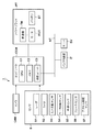
本実施形態の車両は自動運転により走行可能な車両であり、図1は、車両1の基本構成を例示する図である。車両1は、センサS、カメラCAM、コンピュータCOM(ECU)を有する。センサSは、例えば、レーダS1、ライダS2、入力回転センサS3、モータ回転センサS4、車速センサS5、ブレーキセンサS6、アクセル開度センサS7等を有する。センサS(レーダS1、ライダS2)およびカメラCAMは、車両1(自車両)および先行車両の情報、前方の信号機等の情報を取得し、コンピュータCOMに入力する。
(Configuration of vehicle control device)
The vehicle according to the present embodiment is a vehicle that can travel by automatic driving, and FIG. 1 is a diagram illustrating a basic configuration of the
また、コンピュータCOMは、車両1の自動運転制御に関する処理を司るCPU(C1)、メモリC2、通信ユニットC3を有する。コンピュータCOMのCPU(C1)は、センサS(レーダS1、ライダS2)およびカメラCAMから入力された先行車両の情報に基づいて、先行車両に追従して停車する自車両の停車位置を判定することができる。また、コンピュータCOMのCPU(C1)は、センサS(レーダS1、ライダS2)およびカメラCAMから入力された信号機の情報として、信号機が赤信号である場合、信号機の手前で停車する自車両の停車位置を判定することができる。
Further, the computer COM has a CPU (C1) that performs processing related to automatic driving control of the
通信ユニットC3は、ネットワークNTと接続して、道路交通情報を提供するネットワーク上のサーバSVや、通信機能を有するインフラ装置ITや、通信機能を有する他車両との間で通信可能に構成されている。通信ユニットC3は、例えば、光ビーコンから提供される信号情報を取得し、CPU(C1)は、通信ユニットC3が取得した信号情報に基づいて前方が赤信号かを判定することも可能である。コンピュータCOMのCPU(C1)は、通信ユニットC3により取得された信号情報に基づいて、信号機が赤信号である場合、あるいは、赤信号になるタイミングを求め、信号機の手前で停車する自車両の停車位置を判定することができる。 The communication unit C3 is connected to the network NT and configured to be able to communicate with a server SV on the network that provides road traffic information, an infrastructure device IT having a communication function, and another vehicle having a communication function. I have. The communication unit C3 acquires, for example, signal information provided from an optical beacon, and the CPU (C1) can determine whether the front is a red light based on the signal information acquired by the communication unit C3. Based on the signal information acquired by the communication unit C3, the CPU (C1) of the computer COM determines whether the traffic light is a red traffic light or determines the timing at which the traffic light becomes a red traffic light, and stops the own vehicle that stops before the traffic light. The position can be determined.
通信ユニットC3は、外部から地図情報を取得することが可能であり、CPU(C1)は、通信ユニットC3が取得した地図情報に基づいて、自車両が走行する道路の前方が一時停止かを判定することができる。また、通信ユニットC3は、道路交通情報通信システムから提供される渋滞情報を取得することが可能であり、CPU(C1)は、通信ユニットC3により取得された渋滞情報に基づいて、自車両が走行する道路の前方が渋滞しているかを判定することができる。 The communication unit C3 can acquire map information from the outside, and the CPU (C1) determines whether or not the front of the road on which the vehicle runs is temporarily stopped based on the map information acquired by the communication unit C3. can do. Further, the communication unit C3 can acquire the traffic jam information provided from the road traffic information communication system, and the CPU (C1) operates the vehicle based on the traffic jam information acquired by the communication unit C3. It can be determined whether there is traffic congestion ahead of the road where the traffic is going.
また、通信ユニットC3は、車車間通信が可能であり、車両1(自車両)の停車位置の情報を、車両1(自車両)の後続車両へ発信することが可能である。また、通信ユニットC3は、先行車両が停車する停車位置の情報を車車間通信により取得し、取得した先行車両の停車位置の情報に基づいて、車両1(自車両)の停車位置の情報を取得することが可能である。 The communication unit C3 is capable of inter-vehicle communication, and is capable of transmitting information on a stop position of the vehicle 1 (own vehicle) to a vehicle following the vehicle 1 (own vehicle). Further, the communication unit C3 acquires information on the stop position where the preceding vehicle stops, by inter-vehicle communication, and acquires information on the stop position of the vehicle 1 (own vehicle) based on the acquired information on the stop position of the preceding vehicle. It is possible to
本実施形態において、通信ユニットC3は、自車両が停車する停車位置の情報を取得する取得部として機能する。また、コンピュータCOMのCPU(C1)は、通信ユニットC3が取得した情報に基づいて、停車位置へ向けて自車両の減速制御を行う制御部として機能する。 In the present embodiment, the communication unit C3 functions as an acquisition unit that acquires information on the stop position where the host vehicle stops. Further, the CPU (C1) of the computer COM functions as a control unit that controls deceleration of the own vehicle toward the stop position based on the information acquired by the communication unit C3.
コンピュータCOMは、センサS(レーダS1、ライダS2)およびカメラCAMから入力された情報に画像処理を行い、自車両の周囲に存在する物標(オブジェクト)を抽出することが可能である。コンピュータCOMは、センサS(レーダS1、ライダS2)およびカメラCAMにより取得された画像から、物標を抽出し、自車両の周囲にどのような物標が配置されているか、自車両と周囲の物標との相対的な位置関係を解析する。例えば、物標として、自車両の前方を走行する先行車両を抽出し、自車両と先行車両との間の車間距離(実車間距離)や先行車両の停車状態等を取得することができる。 The computer COM can perform image processing on information input from the sensors S (radar S1 and lidar S2) and the camera CAM to extract a target (object) existing around the own vehicle. The computer COM extracts a target from the images acquired by the sensor S (radar S1, lidar S2) and the camera CAM, and determines what target is placed around the own vehicle, Analyze the relative positional relationship with the target. For example, a preceding vehicle running ahead of the host vehicle is extracted as a target, and the inter-vehicle distance (actual inter-vehicle distance) between the host vehicle and the preceding vehicle, the stopped state of the preceding vehicle, and the like can be acquired.
入力回転センサS3は、モータMOTから変速機TMに入力される入力軸の回転数(回転速度)を検出するセンサであり、モータ回転センサS4は、モータMOTの回転軸の回転数(回転速度)を検出するセンサである。また、車速センサS5は車両1の車速を検出するセンサである。入力回転センサS3、モータ回転センサS4および車速センサS5の検出結果はコンピュータCOMに入力される。
The input rotation sensor S3 is a sensor that detects the rotation speed (rotation speed) of the input shaft input from the motor MOT to the transmission TM, and the motor rotation sensor S4 is the rotation speed (rotation speed) of the rotation shaft of the motor MOT. Is a sensor that detects The vehicle speed sensor S5 is a sensor that detects the vehicle speed of the
ブレーキセンサS6は、ドライバーによるブレーキペダルの踏み込み量や踏み込み操作の有無を検出し、検出した情報をコンピュータCOMに入力する。アクセル開度センサS7は、ドライバーによるアクセルペダルの踏み込み量(アクセル開度)を検出し、検出した情報をコンピュータ(COM)に入力する。 The brake sensor S6 detects the amount of depression of the brake pedal by the driver and the presence or absence of the depression operation, and inputs the detected information to the computer COM. The accelerator opening sensor S7 detects an amount of depression of an accelerator pedal (accelerator opening) by a driver, and inputs the detected information to a computer (COM).
コンピュータ(COM)は、車両1を駆動するためのパワープラントPTを制御する。パワープラントPTは車両1の駆動輪を回転させる駆動力を出力する機構であり、例えば、モータMOTと変速機TMとを含む。パワープラントPTには、更にエンジンを含んでもよい。
The computer (COM) controls a power plant PT for driving the
モータMOTは、電動機としての機能と発電機としての機能を兼ね備えた電動発電機(モータジェネレータ)である。モータMOTは、バッテリBTと電気的に接続されており、コンピュータCOMにより制御される。モータMOTの回転軸は、変速機TMの所定の変速段を介して車両1の駆動輪と機械的に接続されている。
The motor MOT is a motor generator (motor generator) having both a function as a motor and a function as a generator. Motor MOT is electrically connected to battery BT, and is controlled by computer COM. The rotating shaft of the motor MOT is mechanically connected to driving wheels of the
モータMOTは、電動機として機能する場合には、バッテリBTの電力を消費して駆動輪を駆動する。一方、発電機として機能する場合には、駆動輪の回転を利用して回生発電を行い、駆動輪に回生減速トルクを働かせるとともにバッテリBTを充電する。 When functioning as a motor, the motor MOT consumes power of the battery BT to drive the drive wheels. On the other hand, when functioning as a generator, regenerative power generation is performed using the rotation of the drive wheels to apply regenerative deceleration torque to the drive wheels and charge the battery BT.
車両1は、センサSおよびカメラCAMの情報、通信ユニットC3が通信により取得した情報、CPU(C1)が演算した情報を用いて、パワープラントPTを制御して、ドライバーの操作に基づく手動運転モード、または、車両1が有する自動運転機能による自動運転モードにより走行することが可能である。CPU(C1)は、停車位置に停車するために減速を開始する減速開始位置を決定し、停車位置へ向けて車両の減速制御を行う際に、手動運転モードと自動運転モードとでパワープラントPTの減速制御を切り替える。
The
図1に示すコンピュータCOMを車両1に搭載する場合、コンピュータCOMを、例えば、センサSやカメラCAMの情報を処理する認識処理系のECUや画像処理系のECU内に配置してもよいし、通信ユニットや入出力装置を制御するECU内に配置してもよいし、車両の駆動制御を行う制御ユニット内のECUや、ブレーキ装置の制御を行うECUや、自動運転用のECU内に配置してもよい。
When the computer COM shown in FIG. 1 is mounted on the
図2は、車両1(自車両)を制御するための制御ブロック図の構成例を示す図である。図2において、車両1はその概略が平面図と側面図とで示されている。車両1は一例としてセダンタイプの四輪の乗用車である。例えば、以下に説明する図2のように、センサS用のECU、カメラ用のECU、及び自動運転用のECU等、車両制御装置100を構成する複数のECUに機能を分散させてもよい。
FIG. 2 is a diagram illustrating a configuration example of a control block diagram for controlling the vehicle 1 (own vehicle). In FIG. 2, the
図2の制御ユニット2は、車両1の各部を制御する。制御ユニット2は車内ネットワークにより通信可能に接続された複数のECU20〜29を含む。各ECU(Engine Control Unit)は、CPU(Central Processing Unit)に代表されるプロセッサ、半導体メモリ等の記憶デバイス、外部デバイスとのインタフェース等を含む。記憶デバイスにはプロセッサが実行するプログラムやプロセッサが処理に使用するデータ等が格納される。各ECUはプロセッサ、記憶デバイスおよびインタフェース等を複数備えていてもよい。
The
以下、各ECU20〜29が担当する機能等について説明する。なお、ECUの数や、担当する機能については、車両1の適宜設計可能であり、本実施形態よりも細分化したり、あるいは、統合することが可能である。
Hereinafter, functions and the like assigned by the
ECU20は、本実施形態に係る車両1(自車両)の自動運転に関わる車両制御を実行する。自動運転においては、車両1の操舵と、加減速の少なくともいずれか一方を自動制御する。自動運転に関わる具体的な制御に関する処理については後に詳細に説明する。
The
車両の走行制御において、ECU20は、車両の周囲の状況を示す車両1(自車両)の位置、車両1に周辺に存在する他車両の相対的な位置、車両1が走行する道路の情報や地図情報等に基づいて、自動運転レベルを設定して車両の自動運転走行を制御する。
In the traveling control of the vehicle, the
ここで、自動運転レベルとは、車両の加速、操舵、制動に関する操作に関して制御部(例えば、ECU20)が制御する度合と、車両を操作する運転者(ドライバー)における車両操作の関与度と、に応じて複数の段階に分類されている操作制御情報である。 Here, the automatic driving level refers to the degree to which the control unit (for example, the ECU 20) controls operations related to acceleration, steering, and braking of the vehicle, and the degree of involvement of the vehicle operation by the driver (driver) operating the vehicle. The operation control information is classified into a plurality of stages according to the operation control information.
ECU21は、電動パワーステアリング装置3を制御する。電動パワーステアリング装置3は、ステアリングホイール31に対する運転者の運転操作(操舵操作)に応じて前輪を操舵する機構を含む。また、電動パワーステアリング装置3は操舵操作をアシストしたり、あるいは、前輪を自動操舵するための駆動力を発揮するモータや、操舵角を検知するセンサ等を含む。車両1の運転状態が自動運転の場合、ECU21は、ECU20からの指示に対応して電動パワーステアリング装置3を自動制御し、車両1の進行方向を制御する。
The
ECU22および23は、車両の周囲状況を検知する検知ユニット41〜43の制御および検知結果の情報処理を行う。検知ユニット41は、例えば、車両1の前方を撮影するカメラであり(以下、カメラ41と表記する場合がある。)、本実施形態の場合、車両1のルーフ前部に2つ設けられている。カメラ41が撮影した画像の解析(画像処理)により、物標の輪郭抽出や、道路上の車線の区分線(白線等)を抽出可能である。
The
検知ユニット42(ライダ検出部)は、例えば、ライダ(レーザレーダ)であり(以下、ライダ42と表記する場合がある)、光により車両1の周囲の物標を検知したり、物標との距離を測距する。本実施形態の場合、ライダ42は車両の周囲に複数設けられている。図2に示す例では、ライダ42は、例えば、5つ設けられており、車両1の前部の各隅部に1つずつ、後部中央に1つ、後部各側方に1つずつ設けられている。検知ユニット43(レーダ検出部)は、例えば、ミリ波レーダであり(以下、レーダ43と表記する場合がある)、電波により車両1の周囲の物標を検知したり、物標との距離を測距する。本実施形態の場合、レーダ43は車両の周囲に複数設けられている。図2に示す例では、レーダ43は、例えば、5つ設けられており、車両1の前部中央に1つ、前部各隅部に1つずつ、後部各隅部に一つずつ設けられている。
The detection unit 42 (a lidar detection unit) is, for example, a lidar (laser radar) (hereinafter, sometimes referred to as a lidar 42), and detects a target around the
ECU22は、一方のカメラ41と、各ライダ42の制御および検知結果の情報処理を行う。ECU23は、他方のカメラ41と、各レーダ43の制御および検知結果の情報処理を行う。車両の周囲状況を検知する装置を二組備えたことで、検知結果の信頼性を向上でき、また、カメラ、ライダ、レーダといった種類の異なる検知ユニットを備えたことで、車両の周辺環境の解析を多面的に行うことができる。尚、ECU22およびECU23を一つのECUにまとめてもよい。
The
ECU24は、ジャイロセンサ5、GPSセンサ24b、通信ユニット24cの制御および検知結果あるいは通信結果の情報処理を行う。ジャイロセンサ5は車両1の回転運動を検知する。ジャイロセンサ5の検知結果や、車輪速等により車両1の進路を判定することができる。GPSセンサ24bは、車両1の現在位置を検知する。通信ユニット24cは、地図情報や交通情報を提供するサーバと無線通信を行い、これらの情報を取得する。ECU24は、記憶デバイスに構築された地図情報のデータベース24aにアクセス可能であり、ECU24は現在地から目的地へのルート探索等を行う。データベース24aはネットワーク上に配置可能であり、通信ユニット24cがネットワーク上のデータベース24aにアクセスして、情報を取得することが可能である。
The
ECU25は、車車間通信用の通信ユニット25aを備える。通信ユニット25aは、周辺の他車両と無線通信を行い、車両間での情報交換を行う。
The
ECU26は、パワープラント6を制御する。パワープラント6は車両1の駆動輪を回転させる駆動力を出力する機構であり、例えば、モータMOTと、変速機TMを含む。パワープラント6には、更にエンジンを含んでもよい。ECU26は、例えば、アクセルペダル7Aに設けた操作検知センサ7aにより検知した運転者の運転操作(アクセル操作あるいは加速操作)に対応してエンジンの出力を制御したり、車速センサ7cが検知した車速等の情報に基づいて変速機TMの変速段を切り替える。車両1の運転状態が自動運転の場合、ECU26は、ECU20からの指示に対応してパワープラント6を自動制御し、車両1の加減速を制御する。
The
ECU27は、方向指示器8を含む灯火器(ヘッドライト、テールライト等)を制御する。図2の例の場合、方向指示器8は車両1の前部、ドアミラーおよび後部に設けられている。
The
ECU28は、入出力装置9の制御を行う。入出力装置9は運転者に対する情報の出力と、運転者からの情報の入力の受け付けを行う。音声出力装置91は運転者に対して音声により情報を報知する。表示装置92は運転者に対して画像の表示により情報を報知する。表示装置92は例えば運転席表面に配置され、インストルメントパネル等を構成する。なお、ここでは、音声と表示を例示したが振動や光により情報を報知してもよい。また、音声、表示、振動または光のうちの複数を組み合わせて情報を報知してもよい。更に、報知すべき情報のレベル(例えば緊急度)に応じて、組み合わせを異ならせたり、報知態様を異ならせてもよい。
The
入力装置93は運転者が操作可能な位置に配置され、車両1に対する指示を行うスイッチ群であるが、音声入力装置も含まれてもよい。
The
ECU29は、ブレーキ装置10やパーキングブレーキ(不図示)を制御する。ブレーキ装置10は例えばディスクブレーキ装置であり、車両1の各車輪に設けられ、車輪の回転に抵抗を加えることで車両1を減速あるいは停止させる。ECU29は、例えば、ブレーキペダル7Bに設けた操作検知センサ7bにより検知した運転者の運転操作(ブレーキ操作)に対応してブレーキ装置10の作動を制御する。
The
車両1の運転状態が自動運転の場合、ECU29は、ECU20からの指示に対応してブレーキ装置10を自動制御し、車両1の減速および停止を制御する。ブレーキ装置10やパーキングブレーキは車両1の停止状態を維持するために作動することもできる。また、パワープラント6の変速機TMがパーキングロック機構を備える場合、これを車両1の停止状態を維持するために作動することもできる。
When the driving state of the
パワープラント6を自動制御するECU26および、ブレーキ装置10を自動制御して車両1の減速・停止を制御するECU29は、車両1(自車両)が停車する停車位置へ向けて車両1(自車両)の減速制御を行う制御部(以下、「制御部(26、29)」)として機能する。制御部(26、29)は、図1で説明したコンピュータCOMのCPU(C1)の構成に対応する。
The
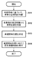
図3は、自動運転モードによる制御部(26、29)の減速制御の処理の流れを説明する図である。まず、ステップS11において、制御部(26、29)は、カメラ41、センサ(ライダ42、レーダ43)、通信ユニット(24c、25a)により取得された、外部情報に基づいて、停車の必要性を判断する。
FIG. 3 is a diagram illustrating a flow of a deceleration control process of the control units (26, 29) in the automatic operation mode. First, in step S11, the control units (26, 29) determine the necessity of stopping based on the external information acquired by the
外部情報としては、例えば、カメラ41、センサ(ライダ42、レーダ43)により取得される先行車両の停車情報、前方の信号機の赤信号の情報、通信ユニット(24c、25a)により取得される地図情報に基づく情報(例えば、前方に一時停止の標識がある等)、道路交通情報に基づく前方の渋滞情報、先行車両との間の車車間通信による先行車両の停車情報等が含まれる。
As the external information, for example, the stop information of the preceding vehicle acquired by the
ステップS12において、制御部(26、29)は、カメラ41、センサ(ライダ42、レーダ43)により取得される車両1(自車両)の周辺の情報を考慮して、車両1(自車両)の停車位置を判断する。
In step S12, the control units (26, 29) consider the information about the vehicle 1 (own vehicle) around the vehicle 1 (own vehicle) acquired by the
ステップS13で、制御部(26、29)は、停車位置に停車するために減速を開始する位置(減速開始位置)を決定する。減速開始位置は、モータMOTによる回生減速トルクとともに、ブレーキ装置10の動作によりブレーキ減速トルクが出力軸に作用する位置である。
In step S13, the control units (26, 29) determine a position (deceleration start position) where deceleration is started to stop at the stop position. The deceleration start position is a position where the brake deceleration torque acts on the output shaft by the operation of the
そして、ステップS14で、制御部(26、29)は、減速開始位置での制動に向けて、回生準備制御を行う。制御部(26、29)は、自動運転モードで減速制御を行う場合、モータの回転軸の起動、モータの回転軸の回転数と変速機の所定の変速段における回転軸の回転数とを合わせる同期制御、及び同期制御されたモータの回転軸と変速機の回転軸とを係合させる係合制御を、手動運転モードにおける減速制御の実行タイミングに比べて早いタイミングで実行する。 Then, in step S14, the control units (26, 29) perform regeneration preparation control for braking at the deceleration start position. When performing deceleration control in the automatic operation mode, the control units (26, 29) match the rotation speed of the rotation shaft of the transmission at a predetermined shift speed with the rotation speed of the rotation shaft of the motor and the rotation speed of the rotation shaft of the motor. The synchronous control and the engagement control for engaging the synchronously controlled rotating shaft of the motor and the rotating shaft of the transmission are executed at a timing earlier than the execution timing of the deceleration control in the manual operation mode.
自動運転モードでは、減速開始位置で、回生減速トルクがブレーキ減速トルクとともに出力軸を介して駆動輪に作用するように、制御部(26、29)は、回生準備制御として、モータMOTの回転軸の起動、およびモータ回転軸の回転数と変速機TMの回転軸(N速段)の回転数とを合わせる同期制御、モータMOTの回転軸とN速段で回転する変速機TMの回転軸とを係合状態(インギヤ状態)にする係合制御を、手動運転モードにおける減速制御に比べて回生準備時間だけ早く前倒しで実行するように制御する。 In the automatic operation mode, the control unit (26, 29) performs the regeneration preparation control so that the regenerative deceleration torque acts on the drive wheels via the output shaft together with the brake deceleration torque at the deceleration start position. And synchronous control for matching the rotation speed of the motor rotation shaft with the rotation speed of the rotation shaft (N speed) of the transmission TM, the rotation shaft of the motor MOT and the rotation shaft of the transmission TM rotating at the N speed. Is controlled to be executed forward by the regeneration preparation time earlier than the deceleration control in the manual operation mode.
ここで、回生準備時間は、回生準備制御(モータ起動、同期制御、係合制御)に要する時間である。 Here, the regeneration preparation time is the time required for the regeneration preparation control (motor start, synchronization control, engagement control).
回生準備制御により、車両1が減速を開始する減速開始位置で、モータMOTの回転軸とN速段で回転する変速機TMの回転軸とを係合した状態(インギヤ状態)にすることができ、減速初期の段階で回生減速トルクを発生させることができる。
By the regenerative preparation control, it is possible to bring the rotating shaft of the motor MOT into engagement with the rotating shaft of the transmission TM rotating at the Nth speed (in-gear state) at the deceleration start position where the
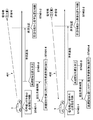
図4A及び図4B停車は、自動運転モードによる制御部(26、29)の減速制御の処理の流れを模式的に説明する図である。 FIGS. 4A and 4B schematically illustrate a flow of a deceleration control process of the control units (26, 29) in the automatic driving mode.
図4Aに示す決定手法例401では、車両1のカメラ41、センサ(ライダ42、レーダ43)により信号機が赤信号である信号情報が取得されると、車両1の制御部(26、29)は、信号機からの情報に基づいて、停車の必要性を判断する(ST401−1)。制御部(26、29)は、周辺情報から車両1(自車両)の停車位置を判断し(ST401−2)、停車位置から手前側に停車距離だけ離れた位置を減速開始位置として決定する(ST401−3)。
In the determination method example 401 illustrated in FIG. 4A, when the
ここで、制御部(26、29)は、車両1の走行速度やブレーキ作用時の減速トルクに関する情報に基づいて、演算処理により停車位置に停車するために要する停車距離を求めることが可能である。あるいは、走行速度および減速トルクに関する情報と停車距離とを対応付けたテーブルをメモリC2に保存し、制御部(26、29)は、メモリC2のテーブルを参照して、走行時の走行速度から停車距離を取得することも可能である。
Here, the control units (26, 29) can calculate the stop distance required to stop at the stop position by arithmetic processing based on information on the traveling speed of the
そして、減速開始位置が決まると、制御部(26、29)は、減速開始位置に向けて回生準備制御を行う(ST401−4)。 When the deceleration start position is determined, the control units (26, 29) perform regeneration preparation control toward the deceleration start position (ST401-4).
図4Aに示す決定手法例402では、車両1は、通信ユニット24cによって信号機から受信した信号情報に基づいて、停車の必要性を判断する(ST402−1)。制御部(26、29)は、周辺情報から車両1(自車両)の停車位置を判断し(ST402−2)、停車位置から手前側に停車距離だけ離れた位置を減速開始位置として決定する(ST402−3)。そして、減速開始位置が決まると、制御部(26、29)は、減速開始位置に向けて回生準備制御を行う(ST402−4)。
In determination method example 402 shown in FIG. 4A,
図4Bに示す決定手法例403では、車両1のカメラ41、センサ(ライダ42、レーダ43)により先行車両11(他車両)が停車状態であることが検出されると(ST403−1)、車両1の制御部(26、29)は、先行車両11の停車状態情報に基づいて、停車の必要性を判断する(ST403−1)。制御部(26、29)は、先行車両11の停車位置と、周辺情報から車両1(自車両)の停車位置を判断し(ST403−2)、停車位置から手前側に停車距離だけ離れた位置を減速開始位置として決定する(ST403−3)。そして、減速開始位置が決まると、制御部(26、29)は、減速開始位置に向けて回生準備制御を行う(ST403−4)。
In the determination method example 403 illustrated in FIG. 4B, when the
また、決定手法例404では、車車間通信により先行車両11から送信(ST404−1)された停車位置情報が車両1の通信ユニット25aにより受信されると、車両1の制御部(26、29)は、受信した停車位置情報に基づいて、停車の必要性を判断する(ST404−2)。
Further, in the determination method example 404, when the stop position information transmitted from the preceding
制御部(26、29)は、先行車両11の停車位置と、周辺情報から車両1(自車両)の停車位置を判断し(ST404−3)、停車位置から手前側に停車距離だけ離れた位置を減速開始位置として決定する(ST404−4)。そして、減速開始位置が決まると、制御部(26、29)は、減速開始位置に向けて回生準備制御を行う(ST404−5)。
The control unit (26, 29) determines the stop position of the vehicle 1 (own vehicle) from the stop position of the preceding
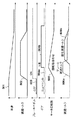
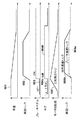
図5は、手動運転モードで減速する場合のブレーキ減速トルクと回生減速トルクの出力タイミングを説明する図である。 FIG. 5 is a diagram illustrating the output timing of the brake deceleration torque and the regenerative deceleration torque when decelerating in the manual operation mode.
図5において、波形501は、車両1(自車両)の車速の変化を示し、波形502は減速トルクの変化を示している。波形503はブレーキペダル7B(図2)のオン(ON)、オフ(OFF)を示しており、ブレーキペダル7Bがオン(ON)の状態で、減速トルク(波形502)が立ち上がり、車速は低下する(波形501)。ブレーキペダル7Bがオフ(OFF)の状態では、車両1はコースティング状態で走行する。
In FIG. 5, a
コースティング状態では、制御部(26、29)は、変速機TMを制御して、ギヤ段を非係合状態にするとともにクラッチをオフにしてニュートラル状態として、モータMOTと駆動輪とを切り離した状態(惰性走行状態)にする。ブレーキペダルオフ(OFF)の状態で、制御部(26、29)は、モータMOTの回転数をゼロに制御する。 In the coasting state, the control units (26, 29) control the transmission TM to disengage the gear and disengage the clutch to set the clutch in the neutral state, thereby disconnecting the motor MOT from the drive wheels. State (coasting state). In the state where the brake pedal is off (OFF), the control units (26, 29) control the number of revolutions of the motor MOT to zero.
波形504aは、変速機TMがニュートラルの状態を示し、波形504bは、変速機TMのギヤ段がN速段に係合した状態を示している。ここで、変速機TMのN速段は、駆動輪が接続する出力軸の回転を、変速機TMの動力伝達経路を介してモータMOTの回転軸に伝達する変速段である。
A waveform 504a shows a state where the transmission TM is in a neutral state, and a
N速段で回転する回転軸の回転数は、入力回転センサS3により検出され、制御部(26、29)(図1のコンピュータCOM)に入力される。 The number of rotations of the rotating shaft rotating at the Nth speed is detected by the input rotation sensor S3 and input to the control units (26, 29) (computer COM in FIG. 1).
波形505は、モータMOTの回転軸の回転数の変化を示す波形であり、制御部(26、29)は、ブレーキペダル7Bがオン(ON)になったタイミングで、モータMOTが回転を開始するように回転制御を行う。モータMOTの回転軸の回転数は、モータ回転センサS4により検出され、制御部(26、29)(図1のコンピュータCOM)に入力される。
A
制御部(26、29)は、N速段で回転する回転軸の回転数と、モータMOTの回転軸の回転数とを合わせる同期制御を行う。両回転軸の回転数の差分が予め定めた許容回転数以下になったとき、制御部(26、29)は、モータMOTの回転軸とN速段で回転する変速機TMの回転軸とを係合した状態(インギヤ状態)にするようモータMOTおよび変速機TMを制御する。 The control units (26, 29) perform synchronous control to match the rotation speed of the rotation shaft rotating at the Nth speed with the rotation speed of the rotation shaft of the motor MOT. When the difference between the rotation speeds of the two rotation shafts becomes equal to or less than a predetermined allowable rotation speed, the control unit (26, 29) determines the rotation shaft of the motor MOT and the rotation shaft of the transmission TM rotating at the Nth speed. The motor MOT and the transmission TM are controlled so as to be engaged (in-gear state).
波形506aは、ブレーキ減速トルクの出力波形を示し、波形506bは、回生減速トルクの出力波形を示す。ブレーキペダル7Bがオン(ON)の状態になると、ブレーキ装置10からブレーキ減速トルクが出力される。制御部(26、29)は、手動運転モードで減速制御を行う場合、減速開始位置で、ブレーキ装置によるブレーキ減速トルクを発生させる。
A
回生減速トルク(波形506b)は、モータMOTの回転軸とN速段で回転する変速機TMの回転軸とを係合した状態(インギヤ状態)になると出力される。モータMOTは発電機として機能し、駆動輪の回転を利用して回生発電を行い、回生減速トルクを発生させる。発生した回生減速トルクは変速機TMの出力軸を介して駆動輪に作用する。手動運転モードで減速制御を行う場合、減速開始位置では、回生減速トルク(波形506b)は発生せず、ブレーキ減速トルクの発生よりも遅れて回生減速トルク(波形506b)は発生する。
The regenerative deceleration torque (
図6は、自動運転モードで減速する場合のブレーキ減速トルクと回生減速トルクの出力タイミングを説明する図である。 FIG. 6 is a diagram illustrating output timings of the brake deceleration torque and the regenerative deceleration torque when decelerating in the automatic operation mode.
図6において、波形601は、車両1(自車両)の車速の変化を示し、波形602は減速トルクの変化を示している。波形603はブレーキペダル7Bのオン(ON)、オフ(OFF)を示しており、ブレーキペダル7Bがオン(ON)の状態で、減速トルク(波形602)が立ち上がり、車速は低下する(波形601)。ブレーキペダル7Bがオフ(OFF)の状態では、車両1はコースティング状態で走行する。
In FIG. 6, a
コースティング状態では、制御部(26、29)は、変速機TMを制御して、ギヤ段を非係合状態にするとともにクラッチをオフにしてニュートラル状態として、モータMOTと駆動輪とを切り離した状態(惰性走行状態)にする。ブレーキペダル7Bがオフ(OFF)の状態で、制御部(26、29)は、モータMOTの回転数をゼロに制御する。フリクション要素を切り離すことで減速は抑えられ航続距離は拡大される。
In the coasting state, the control units (26, 29) control the transmission TM to disengage the gear and disengage the clutch to set the clutch in the neutral state, thereby disconnecting the motor MOT from the drive wheels. State (coasting state). When the
自動運転モードでは、回生準備制御として、モータMOTの回転軸の起動、およびモータ回転軸の回転数と変速機TMの回転軸(N速段)の回転数とを合わせる同期制御、モータMOTの回転軸とN速段で回転する変速機TMの回転軸とをインギヤ状態にする係合制御を、手動運転モードにおける減速制御に比べて回生準備時間だけ早く前倒しで実行するように制御する。回生準備時間は、回生準備制御(モータ起動、同期制御、係合制御)に要する時間であり、回生準備制御により、ブレーキペダルオン(ON)のタイミング、すなわち、車両1が減速を開始するタイミングで、モータMOTの回転軸とN速段で回転する変速機TMの回転軸とを係合した状態(インギヤ状態)にすることができる。
In the automatic operation mode, the regenerative preparation control includes starting the rotation shaft of the motor MOT, synchronizing the rotation speed of the motor rotation shaft with the rotation speed of the rotation shaft (Nth speed) of the transmission TM, and rotating the motor MOT. The engagement control for bringing the shaft and the rotating shaft of the transmission TM rotating at the Nth gear into an in-gear state is controlled so as to be executed ahead of schedule by the regeneration preparation time earlier than the deceleration control in the manual operation mode. The regenerative preparation time is a time required for regenerative preparation control (motor start, synchronization control, engagement control), and is performed at a timing when the brake pedal is turned on (ON) by the regenerative preparation control, that is, a timing when the
波形604aは、変速機TMがニュートラルの状態を示し、波形604bは、変速機TMのギヤ段がN速段に係合した状態を示している。ここで、変速機TMのN速段は、駆動輪が接続する出力軸の回転を、変速機TMの動力伝達経路を介してモータMOTに伝達する変速段である。
A waveform 604a shows a state where the transmission TM is in a neutral state, and a
N速段で回転する回転軸の回転数は、入力回転センサS3により検出され、制御部(26、29)(図1のコンピュータCOM)に入力される。 The number of rotations of the rotating shaft rotating at the Nth speed is detected by the input rotation sensor S3 and input to the control units (26, 29) (computer COM in FIG. 1).
波形605は、モータMOTの回転軸の回転数の変化を示す波形であり、制御部(26、29)は、手動運転モードにおける減速制御に比べて回生準備時間だけ早く前倒しで、回生準備制御を実行するようにモータMOTおよび変速機TMを制御する。
A
モータMOTの回転軸の回転数は、モータ回転センサS4により検出され、制御部(26、29)(図1のコンピュータCOM)に入力される。制御部(26、29)は、モータ回転軸の回転数と変速機TMの回転軸(N速段)の回転数との回転数合わせ(同期制御)を行い、ブレーキペダル7Bがオン(ON)になったタイミングで、モータMOTの回転軸とN速段で回転する変速機TMの回転軸とを係合した状態(インギヤ状態)にする。
The number of rotations of the rotation shaft of the motor MOT is detected by the motor rotation sensor S4 and input to the control units (26, 29) (computer COM in FIG. 1). The control units (26, 29) adjust the rotation speed of the motor rotation shaft and the rotation speed of the rotation shaft (Nth speed) of the transmission TM (synchronous control), and turn on (ON) the
波形606aはブレーキ減速トルクの出力波形を示し、波形606bは、回生減速トルクの出力波形を示す。ブレーキペダル7Bがオン(ON)の状態になると、ブレーキ装置10からブレーキ減速トルクが出力され、モータMOTから回生減速トルクが出力される。すなわち、制御部(26、29)は、自動運転モードで減速制御を行う場合、ブレーキペダル7Bがオン(ON)になる減速開始位置で、ブレーキ減速トルク606aおよびモータの回生減速トルク606bを発生させる。
A
減速開始位置を予測して、回生準備制御を、手動運転モードにおける減速制御に比べて回生準備時間だけ早く前倒しで実行することにより、回生減速トルクを減速初期の段階から発生させることが可能になる。 By predicting the deceleration start position and executing the regenerative preparation control ahead of time by the regenerative preparation time compared to the deceleration control in the manual operation mode, the regenerative deceleration torque can be generated from the initial stage of the deceleration. .
また、各実施形態で説明された1以上の機能を実現するプログラムは、ネットワーク又は記憶媒体を介してシステム又は装置に供給され、該システム又は装置のコンピュータにおける1以上のプロセッサは、このプログラムを読み出して実行することができる。このような態様によっても本発明は実現可能である。 Further, a program for realizing one or more functions described in each embodiment is supplied to a system or an apparatus via a network or a storage medium, and one or more processors in a computer of the system or the apparatus read out the program and read the program. Can be executed. The present invention can also be realized by such an embodiment.
<実施形態のまとめ>
構成1.上記実施形態の制御装置は、モータ(例えば、MOT)と前記モータの回転を出力軸に伝達する変速機(例えば、TM)とをパワープラント(例えば、PT)として有する車両(例えば、1)の制御装置(例えば、COM)であって、
前記車両が停車する停車位置の情報を取得する取得手段(例えば、CAM、S1、S2、41、42、43)と、
前記停車位置に停車するために減速を開始する減速開始位置を決定する決定手段(例えば、C1、26、29)と、
前記停車位置へ向けて前記車両の減速制御を行う際に、手動運転モードと自動運転モードとで前記パワープラントの減速制御を切り替える制御手段(例えば、C1、26、29)と、を備え、
前記制御手段(C1、26、29)は、
前記手動運転モードで減速制御を行う場合、前記減速開始位置で、ブレーキ装置によるブレーキ減速トルクを発生させ(例えば、図5の506a)、
前記自動運転モードで減速制御を行う場合、前記減速開始位置で、前記ブレーキ減速トルクおよび前記モータの回生減速トルクを発生(例えば、図6の606a、606b)させることを特徴とする。
<Summary of Embodiment>
Acquiring means (for example, CAM, S1, S2, 41, 42, 43) for acquiring information of a stop position where the vehicle stops,
Determining means (for example, C1, 26, 29) for determining a deceleration start position at which deceleration is started to stop at the stop position;
Control means (for example, C1, 26, 29) for switching the deceleration control of the power plant between a manual operation mode and an automatic operation mode when performing the deceleration control of the vehicle toward the stop position;
The control means (C1, 26, 29)
When deceleration control is performed in the manual operation mode, a brake deceleration torque is generated by the brake device at the deceleration start position (for example, 506a in FIG. 5).
When deceleration control is performed in the automatic operation mode, the brake deceleration torque and the regenerative deceleration torque of the motor are generated at the deceleration start position (for example, 606a and 606b in FIG. 6).
構成2.上記実施形態の制御装置(COM)であって、車車間通信が可能な通信手段(例えば、C3、25a)を更に備え、前記通信手段は、前記停車位置の情報を、前記車両の後続車両へ発信することを特徴とする。
構成3.上記実施形態の制御装置(COM)であって、前記通信手段(例えば、C3、25a)は、先行車両が停車する停車位置の情報を前記車車間通信により取得し、前記取得手段は、前記通信手段が取得した先行車両の停車位置の情報に基づいて、前記車両の停車位置の情報を取得することを特徴とする。
構成4.上記実施形態の制御装置(COM)であって、前記制御手段(C1、26、29)は、前記自動運転モードで減速制御を行う場合、
前記モータの回転軸の起動、
前記モータの回転軸の回転数と前記変速機の所定の変速段における回転軸の回転数とを合わせる同期制御、及び
前記同期制御された前記モータの回転軸と前記変速機の回転軸とを係合させる係合制御を、前記手動運転モードにおける減速制御の実行タイミングに比べて早いタイミングで実行することを特徴とする。
Starting the rotation axis of the motor,
Synchronous control for adjusting the rotational speed of the rotating shaft of the motor to the rotational speed of the rotating shaft at a predetermined shift speed of the transmission; and controlling the synchronously controlled rotating shaft of the motor and the rotating shaft of the transmission. The engagement control to be combined is executed at a timing earlier than the execution timing of the deceleration control in the manual operation mode.
構成5.上記実施形態の制御装置(COM)であって、前記変速機の所定の変速段(例えば、N速段)は、駆動輪が接続する前記出力軸の回転を、前記変速機の動力伝達経路を介して前記モータの回転軸に伝達する変速段であることを特徴とする。
構成6.上記実施形態の制御方法は、モータと前記モータの回転を出力軸に伝達する変速機とをパワープラントとして有する車両の制御方法であって、
前記車両が停車する停車位置の情報を取得する取得工程(例えば、図3のステップS12)と、
前記停車位置に停車するために減速を開始する減速開始位置を決定する決定工程(例えば、図3のステップS13)と、
前記停車位置へ向けて前記車両の減速制御を行う際に、手動運転モードと自動運転モードとで前記パワープラントの減速制御を切り替える制御工程(図3のステップS14)と、を有し、
前記制御工程では、
前記手動運転モードで減速制御を行う場合、前記減速開始位置で、ブレーキ装置によるブレーキ減速トルクを発生させ(例えば、図5の506a)、
前記自動運転モードで減速制御を行う場合、前記減速開始位置で、前記ブレーキ減速トルクおよび前記モータの回生減速トルクを発生(例えば、図6の606a、606b)させることを特徴とする。
Configuration 6. The control method of the embodiment is a control method of a vehicle having a motor and a transmission that transmits rotation of the motor to an output shaft as a power plant,
An acquisition step (for example, step S12 in FIG. 3) for acquiring information on a stop position where the vehicle stops,
A determining step of determining a deceleration start position at which deceleration is started to stop at the stop position (for example, step S13 of FIG. 3);
When performing deceleration control of the vehicle toward the stop position, a control step (step S14 in FIG. 3) of switching the deceleration control of the power plant between a manual operation mode and an automatic operation mode;
In the control step,
When deceleration control is performed in the manual operation mode, a brake deceleration torque is generated by the brake device at the deceleration start position (for example, 506a in FIG. 5).
When deceleration control is performed in the automatic operation mode, the brake deceleration torque and the regenerative deceleration torque of the motor are generated at the deceleration start position (for example, 606a and 606b in FIG. 6).
構成1から構成5の制御装置、および構成6の制御方法によれば、自動運転モードで減速制御を行う際に、停車位置で停車するために減速を開始する位置で、ブレーキ減速トルクおよびモータの回生減速トルクを発生させることが可能になる。すなわち、減速初期の段階で回生減速トルクを利用した制動を行うことが可能になる。
According to the control devices of
構成2の制御装置によれば、自車両の停車位置の情報を、車車間通信により、後続車両へ発信することが可能になる。 According to the control device of the second aspect, it is possible to transmit information on the stop position of the own vehicle to the following vehicle by inter-vehicle communication.
また、構成3の制御装置によれば、先行車両が停車する停車位置の情報を車車間通信により取得し、取得した先行車両の停車位置の情報に基づいて、車両の停車位置の情報を取得することが可能になる。
According to the control device of
1:車両(自車両)、26、29:ECU、1:車両、42:ライダ、43:レーダ、COM:コンピュータ、CAM:カメラ、S:センサ 1: vehicle (own vehicle), 26, 29: ECU, 1: vehicle, 42: lidar, 43: radar, COM: computer, CAM: camera, S: sensor
Claims (5)
前記車両が停車する停車位置の情報を取得する取得手段と、
前記停車位置に停車するために減速を開始する減速開始位置を決定する決定手段と、
前記停車位置へ向けて前記車両の減速制御を行う際に、手動運転モードと自動運転モードとで前記パワープラントの減速制御を切り替える制御手段と、を備え、
前記制御手段は、
前記手動運転モードで減速制御を行う場合、前記減速開始位置で、ブレーキ装置によるブレーキ減速トルクを発生させ、
前記自動運転モードで減速制御を行う場合、
前記モータの回転軸の起動、
前記モータの回転軸の回転数と前記変速機の所定の変速段における回転軸の回転数とを合わせる同期制御、及び
前記同期制御された前記モータの回転軸と前記変速機の回転軸とを係合させる係合制御を、
前記手動運転モードにおける減速制御の実行タイミングに比べて早いタイミングで実行し、前記減速開始位置で、前記ブレーキ減速トルクおよび前記モータの回生減速トルクを発生させる
ことを特徴とする制御装置。 A control device for a vehicle having a motor and a transmission that transmits rotation of the motor to an output shaft as a power plant,
Acquisition means for acquiring information of a stop position where the vehicle stops,
Determining means for determining a deceleration start position to start deceleration to stop at the stop position,
When performing deceleration control of the vehicle toward the stop position, control means that switches deceleration control of the power plant between a manual operation mode and an automatic operation mode,
The control means includes:
When performing deceleration control in the manual operation mode, at the deceleration start position, generate a brake deceleration torque by a brake device,
When performing deceleration control in the automatic operation mode,
Starting the rotation axis of the motor,
Synchronous control for matching the rotation speed of the rotation shaft of the motor with the rotation speed of the rotation shaft at a predetermined shift speed of the transmission; and
Engagement control for engaging the rotation shaft of the motor and the rotation shaft of the transmission, the synchronous control of which is performed,
A control device, which is executed at a timing earlier than the execution timing of the deceleration control in the manual operation mode, and generates the brake deceleration torque and the regenerative deceleration torque of the motor at the deceleration start position.
前記通信手段は、前記停車位置の情報を、前記車両の後続車両へ発信することを特徴とする請求項1に記載の制御装置。 Further comprising communication means capable of inter-vehicle communication,
The control device according to claim 1, wherein the communication unit transmits the information on the stop position to a vehicle following the vehicle.
ことを特徴とする請求項2に記載の制御装置。 The communication means acquires information on a stop position where the preceding vehicle stops by the inter-vehicle communication, and the acquisition means acquires the stop position of the vehicle based on the information on the stop position of the preceding vehicle acquired by the communication means. The control device according to claim 2, wherein the control unit obtains the information of:
前記車両が停車する停車位置の情報を取得する取得工程と、
前記停車位置に停車するために減速を開始する減速開始位置を決定する決定工程と、
前記停車位置へ向けて前記車両の減速制御を行う際に、手動運転モードと自動運転モードとで前記パワープラントの減速制御を切り替える制御工程と、を有し、
前記制御工程では、
前記手動運転モードで減速制御を行う場合、前記減速開始位置で、ブレーキ装置によるブレーキ減速トルクを発生させ、
前記自動運転モードで減速制御を行う場合、
前記モータの回転軸の起動、
前記モータの回転軸の回転数と前記変速機の所定の変速段における回転軸の回転数とを合わせる同期制御、及び
前記同期制御された前記モータの回転軸と前記変速機の回転軸とを係合させる係合制御を、
前記手動運転モードにおける減速制御の実行タイミングに比べて早いタイミングで実行し、前記減速開始位置で、前記ブレーキ減速トルクおよび前記モータの回生減速トルクを発生させる
ことを特徴とする制御方法。 A control method for a vehicle having a motor and a transmission that transmits rotation of the motor to an output shaft as a power plant,
An acquisition step of acquiring information of a stop position at which the vehicle stops,
Determining a deceleration start position to start deceleration to stop at the stop position,
When performing deceleration control of the vehicle toward the stop position, a control step of switching the power plant deceleration control between a manual operation mode and an automatic operation mode,
In the control step,
When performing deceleration control in the manual operation mode, at the deceleration start position, generate a brake deceleration torque by a brake device,
When performing deceleration control in the automatic operation mode,
Starting the rotation axis of the motor,
Synchronous control for matching the rotation speed of the rotation shaft of the motor with the rotation speed of the rotation shaft at a predetermined shift speed of the transmission; and
Engagement control for engaging the rotation shaft of the motor and the rotation shaft of the transmission, the synchronous control of which is performed,
A control method which is executed at a timing earlier than the execution timing of the deceleration control in the manual operation mode, and generates the brake deceleration torque and the regenerative deceleration torque of the motor at the deceleration start position.
Priority Applications (3)
| Application Number | Priority Date | Filing Date | Title |
|---|---|---|---|
| JP2018000184A JP6640887B2 (en) | 2018-01-04 | 2018-01-04 | Control device and control method |
| CN201811556025.4A CN110027542A (en) | 2018-01-04 | 2018-12-19 | Control device and control method |
| US16/225,513 US10836263B2 (en) | 2018-01-04 | 2018-12-19 | Control apparatus and control method |
Applications Claiming Priority (1)
| Application Number | Priority Date | Filing Date | Title |
|---|---|---|---|
| JP2018000184A JP6640887B2 (en) | 2018-01-04 | 2018-01-04 | Control device and control method |
Publications (2)
| Publication Number | Publication Date |
|---|---|
| JP2019119341A JP2019119341A (en) | 2019-07-22 |
| JP6640887B2 true JP6640887B2 (en) | 2020-02-05 |
Family
ID=67059228
Family Applications (1)
| Application Number | Title | Priority Date | Filing Date |
|---|---|---|---|
| JP2018000184A Expired - Fee Related JP6640887B2 (en) | 2018-01-04 | 2018-01-04 | Control device and control method |
Country Status (3)
| Country | Link |
|---|---|
| US (1) | US10836263B2 (en) |
| JP (1) | JP6640887B2 (en) |
| CN (1) | CN110027542A (en) |
Families Citing this family (8)
| Publication number | Priority date | Publication date | Assignee | Title |
|---|---|---|---|---|
| US11345327B2 (en) | 2018-08-06 | 2022-05-31 | Xl Hybrids, Inc. | Throttle signal controller for a dynamic hybrid vehicle |
| CN111433095A (en) * | 2018-10-26 | 2020-07-17 | 深圳市大疆创新科技有限公司 | Automated vehicle actions and related systems and methods |
| CN112055327B (en) * | 2019-06-05 | 2022-09-16 | 华为技术有限公司 | Automatic driving information indicating method, automatic driving information acquiring method, automatic driving information sending method and device |
| CN111038512B (en) * | 2019-12-25 | 2022-06-28 | 联合汽车电子有限公司 | Vehicle deceleration control method and vehicle control unit |
| JP7421725B2 (en) * | 2020-01-21 | 2024-01-25 | マツダ株式会社 | Vehicle sound generator |
| JP2024119461A (en) * | 2023-02-22 | 2024-09-03 | 本田技研工業株式会社 | Information processing device, information processing method, and program |
| JP2025098867A (en) * | 2023-12-20 | 2025-07-02 | 株式会社Subaru | vehicle |
| WO2025225018A1 (en) * | 2024-04-26 | 2025-10-30 | 日産自動車株式会社 | Vehicle travel assistance method and vehicle travel assistance device |
Family Cites Families (8)
| Publication number | Priority date | Publication date | Assignee | Title |
|---|---|---|---|---|
| JP4039215B2 (en) | 2002-11-07 | 2008-01-30 | 日産自動車株式会社 | Vehicle regeneration control device |
| JP5408343B2 (en) * | 2010-04-21 | 2014-02-05 | トヨタ自動車株式会社 | Vehicle parking assist device and electric vehicle including the same |
| JP5360235B2 (en) * | 2010-12-02 | 2013-12-04 | トヨタ自動車株式会社 | Vehicle control device |
| JP2013099166A (en) * | 2011-11-02 | 2013-05-20 | Toyota Motor Corp | Vehicle and method for controlling the same |
| JP5919150B2 (en) * | 2012-09-18 | 2016-05-18 | ダイムラー・アクチェンゲゼルシャフトDaimler AG | Driving assistance device |
| JP6177666B2 (en) * | 2013-11-12 | 2017-08-09 | 日立オートモティブシステムズ株式会社 | Drive control device for moving body |
| JP6650331B2 (en) * | 2016-04-15 | 2020-02-19 | 本田技研工業株式会社 | Vehicle control system, vehicle control method, and vehicle control program |
| JP6390668B2 (en) * | 2016-06-20 | 2018-09-19 | トヨタ自動車株式会社 | Hybrid vehicle |
-
2018
- 2018-01-04 JP JP2018000184A patent/JP6640887B2/en not_active Expired - Fee Related
- 2018-12-19 US US16/225,513 patent/US10836263B2/en active Active
- 2018-12-19 CN CN201811556025.4A patent/CN110027542A/en active Pending
Also Published As
| Publication number | Publication date |
|---|---|
| US10836263B2 (en) | 2020-11-17 |
| CN110027542A (en) | 2019-07-19 |
| US20190202297A1 (en) | 2019-07-04 |
| JP2019119341A (en) | 2019-07-22 |
Similar Documents
| Publication | Publication Date | Title |
|---|---|---|
| JP6640887B2 (en) | Control device and control method | |
| JP6625148B2 (en) | Self-driving vehicle and vehicle control method | |
| JP7154177B2 (en) | Control device, control method and program | |
| JP7055043B2 (en) | Vehicle control device and vehicle | |
| US10967859B2 (en) | Vehicle control apparatus and vehicle control method | |
| CN111532267B (en) | Vehicle and its control device and control method | |
| WO2019043916A1 (en) | Vehicle, and control device and control method therefor | |
| CN113479202B (en) | Travel control device, vehicle, travel control method, and storage medium | |
| JP6933677B2 (en) | Vehicle control devices, vehicle control methods, vehicles and programs | |
| JP6852107B2 (en) | Vehicle control devices, vehicle control methods, vehicles and programs | |
| JP7189088B2 (en) | VEHICLE CONTROL DEVICE, VEHICLE, OPERATING METHOD AND PROGRAM OF VEHICLE CONTROL DEVICE | |
| JP2021149178A (en) | Vehicle controller, vehicle, vehicle controller operation method, and program | |
| US11590979B2 (en) | Vehicle control device, vehicle, vehicle control method, and storage medium | |
| JP2019156355A (en) | Vehicle control device | |
| JP2020199809A (en) | Vehicle control apparatus, vehicle, method for operating vehicle control apparatus, and program | |
| CN113135196B (en) | Vehicle, vehicle control device, and storage medium | |
| US20190278266A1 (en) | Vehicle controlling apparatus and vehicle | |
| JP6982051B2 (en) | Vehicle and its control device | |
| JP2020200029A (en) | Vehicle control apparatus, vehicle, method for operating vehicle control apparatus, and program | |
| JP2022126350A (en) | Recognition device, moving body, recognition method, and program | |
| JP2021143908A (en) | Vehicle control devices, vehicles, vehicle control methods and programs | |
| JP7245859B2 (en) | VEHICLE CONTROL DEVICE, VEHICLE, VEHICLE CONTROL METHOD AND PROGRAM | |
| JP2020199811A (en) | Vehicle control apparatus, vehicle, method for operating vehicle control apparatus, and program | |
| JP2019043368A (en) | Vehicle control device, vehicle, and method |
Legal Events
| Date | Code | Title | Description |
|---|---|---|---|
| A621 | Written request for application examination |
Free format text: JAPANESE INTERMEDIATE CODE: A621 Effective date: 20180927 |
|
| A131 | Notification of reasons for refusal |
Free format text: JAPANESE INTERMEDIATE CODE: A131 Effective date: 20191129 |
|
| A521 | Request for written amendment filed |
Free format text: JAPANESE INTERMEDIATE CODE: A523 Effective date: 20191216 |
|
| TRDD | Decision of grant or rejection written | ||
| A01 | Written decision to grant a patent or to grant a registration (utility model) |
Free format text: JAPANESE INTERMEDIATE CODE: A01 Effective date: 20191223 |
|
| A61 | First payment of annual fees (during grant procedure) |
Free format text: JAPANESE INTERMEDIATE CODE: A61 Effective date: 20191226 |
|
| R150 | Certificate of patent or registration of utility model |
Ref document number: 6640887 Country of ref document: JP Free format text: JAPANESE INTERMEDIATE CODE: R150 |
|
| LAPS | Cancellation because of no payment of annual fees |