JP6638784B2 - Composite cable, composite harness, and vehicle - Google Patents
Composite cable, composite harness, and vehicle Download PDFInfo
- Publication number
- JP6638784B2 JP6638784B2 JP2018173234A JP2018173234A JP6638784B2 JP 6638784 B2 JP6638784 B2 JP 6638784B2 JP 2018173234 A JP2018173234 A JP 2018173234A JP 2018173234 A JP2018173234 A JP 2018173234A JP 6638784 B2 JP6638784 B2 JP 6638784B2
- Authority
- JP
- Japan
- Prior art keywords
- signal line
- composite cable
- power supply
- vehicle
- lines
- Prior art date
- Legal status (The legal status is an assumption and is not a legal conclusion. Google has not performed a legal analysis and makes no representation as to the accuracy of the status listed.)
- Active
Links
Images


Description
本発明は、複合ケーブル、複合ハーネス、及び車両に関し、特に自動車等の車両において車輪側と車体側とを接続する複合ケーブル、複合ハーネス、及び車両に関するものである。 The present invention relates to a composite cable, a composite harness, and a vehicle, and more particularly to a composite cable, a composite harness, and a vehicle for connecting a wheel side and a vehicle body side in a vehicle such as an automobile.
近年、自動車等の車両において、電動式の制動装置が用いられている。 BACKGROUND ART In recent years, electric braking devices have been used in vehicles such as automobiles.
電動式の制動装置としては、電気機械式ブレーキ(Electro−Mechanical Brake、EMB)や、電動パーキングブレーキ(Electric Parking Brake、EPB)が知られている。 As an electric braking device, an electromechanical brake (Electro-Mechanical Brake, EMB) and an electric parking brake (Electric Parking Brake, EPB) are known.
電気機械式ブレーキは、単に電動ブレーキあるいは電気ブレーキとも呼称されるものであり、運転者によるブレーキペダルの操作量(踏力又は変位量)に応じて、車両の各車輪に備えられた専用の電気モータの回転駆動力を制御し、当該電気モータにより駆動されるピストンによりブレーキパッドを車輪のディスクロータに押し付けることにより、運転者の意図に応じた制動力を発生させるように構成されている。 The electromechanical brake is simply called an electric brake or an electric brake, and a dedicated electric motor provided on each wheel of the vehicle according to an operation amount (a pedaling force or a displacement amount) of a brake pedal by a driver. , And a brake force is generated according to the driver's intention by pressing a brake pad against a disk rotor of a wheel by a piston driven by the electric motor.
電動パーキングブレーキは、車両の停止後に運転者がパーキングブレーキ作動スイッチを操作することにより、車両の各車輪に備えられた専用の電気モータを駆動させて、当該電気モータにより駆動されるピストンによりブレーキパッドを車輪のディスクロータに押し付けた状態とし、制動力を発生させるように構成されている。 The electric parking brake drives a dedicated electric motor provided on each wheel of the vehicle by operating a parking brake operation switch after the vehicle stops, and a brake pad is driven by a piston driven by the electric motor. Is pressed against the disk rotor of the wheel to generate a braking force.
また、近年の車両においては、走行中の車輪の回転速度を検出するABS(Anti−lockBrake System)センサや、タイヤの空気圧を検出する空気圧センサ、温度センサなどのセンサ類が車輪に搭載されることが多い。 In recent vehicles, sensors such as an ABS (Anti-lock Brake System) sensor that detects the rotational speed of the running wheel, an air pressure sensor that detects the tire air pressure, and a temperature sensor are mounted on the wheel. There are many.
そこで、車輪に搭載されたセンサ用の信号線や電気機械式ブレーキの制御用の信号線と、電気機械式ブレーキや電動パーキングブレーキ用の電気モータに電力を供給する電源線とを共通のシースに収容した複合ケーブルを用い、車輪側と車体側とを接続することが行われている。この複合ケーブルの端部にコネクタを一体に設けたものは、複合ハーネスと呼称されている。 Therefore, a signal line for sensors mounted on the wheels and a signal line for controlling the electromechanical brake and a power line for supplying electric power to the electric motor for the electromechanical brake and the electric parking brake are shared by a common sheath. The wheel side and the vehicle body side are connected using the accommodated composite cable. A cable in which a connector is integrally provided at the end of the composite cable is called a composite harness.
複合ケーブルでは、電源線と信号線とが共通のシースに収容されるため、電源線を流れる電流に起因する電磁波ノイズが発生するおそれがある。そこで、この電磁波ノイズ対策として、シールド部材により被覆した信号線を用いた複合ケーブルが提案されている(例えば、特許文献1参照)。 In the composite cable, since the power supply line and the signal line are housed in the common sheath, there is a possibility that electromagnetic wave noise due to the current flowing through the power supply line is generated. Therefore, as a countermeasure against the electromagnetic wave noise, a composite cable using a signal line covered with a shield member has been proposed (for example, see Patent Document 1).
しかしながら、上述の従来の複合ケーブルでは、電源線を大電流を流す用途で使用する場合には、電磁波ノイズの影響が非常に大きくなってしまい、この対策のために、シールド部材の大型化や高コスト化を招く場合がある、といった問題がある。シールド部材の大型化は、複合ケーブル全体の大径化につながり、複合ケーブルの配策性の低下の一因ともなる。 However, in the above-described conventional composite cable, when the power supply line is used for flowing a large current, the influence of electromagnetic noise becomes extremely large. There is a problem that the cost may be increased. An increase in the size of the shield member leads to an increase in the diameter of the entire composite cable, which also contributes to a decrease in the layout of the composite cable.
例えば、電気機械式ブレーキ用の電気モータに給電する電源線は、車両の走行中に比較的大きな駆動電流を頻繁に流すことになるため、大径化することなく電磁波ノイズの影響を低減することが可能な複合ケーブルが望まれている。 For example, a power supply line that supplies power to an electric motor for an electromechanical brake frequently flows a relatively large drive current while the vehicle is running, so that the influence of electromagnetic noise can be reduced without increasing the diameter. There is a demand for a composite cable capable of performing the above.
そこで、本発明の目的は、上記課題を解決し、大径化を抑制しつつも電磁波ノイズの影響を低減することが可能な複合ケーブル、複合ハーネス、及び車両を提供することにある。 Therefore, an object of the present invention is to solve the above problems and provide a composite cable, a composite harness, and a vehicle that can reduce the influence of electromagnetic noise while suppressing an increase in diameter.
本発明は上記目的を達成するために創案されたものであり、電気信号を伝送する少なくとも1本の信号線と、電力供給用の少なくとも1対の第1電源線と、前記信号線と前記第1電源線とを一括して被覆するシースと、前記信号線と前記第1電源線との間に配置され、前記信号線と前記第1電源線とを離間させる線状体と、を備え、前記線状体は、車両の停止後に制動力を発生させる電動パーキングブレーキの電気モータに駆動電流を供給する第2電源線、または、信号伝送および電力伝送に使用しないダミー線からなる、複合ケーブルである。 The present invention has been devised to achieve the above object, and has at least one signal line for transmitting an electric signal, at least one pair of first power lines for supplying power, the signal line and the first line. A power supply line and a sheath that collectively covers the power supply line, and a linear body disposed between the signal line and the first power supply line, for separating the signal line and the first power supply line, The linear body is a composite cable including a second power supply line that supplies a drive current to an electric motor of an electric parking brake that generates a braking force after the vehicle stops, or a dummy line that is not used for signal transmission and power transmission. is there.
また、本発明は、前記複合ケーブルと、前記信号線と前記第1電源線の端部のうち、少なくとも何れかの端部に取り付けられたコネクタと、を備えた、複合ハーネスである。
また、本発明は、前記複合ケーブルを用いて、車輪側と車体側とを接続した、車両である。
Further, the present invention is a composite harness comprising: the composite cable; and a connector attached to at least one of the ends of the signal line and the first power supply line.
Further, the present invention is a vehicle in which a wheel side and a vehicle body side are connected using the composite cable.
本発明によれば、大径化を抑制しつつも電磁波ノイズの影響を低減することが可能な複合ケーブル、複合ハーネス、及び車両を提供できる。 According to the present invention, it is possible to provide a composite cable, a composite harness, and a vehicle that can reduce the influence of electromagnetic wave noise while suppressing an increase in diameter.
以下、本発明の実施の形態を添付図面にしたがって説明する。 Hereinafter, embodiments of the present invention will be described with reference to the accompanying drawings.
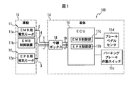
図1は、本実施の形態に係る複合ケーブルを用いた車両の構成を示すブロック図である。 FIG. 1 is a block diagram showing a configuration of a vehicle using the composite cable according to the present embodiment.
図1に示すように、車両100には、電動式の制動装置として、電気機械式ブレーキ(以下、EMBという)11と、電動パーキングブレーキ(以下、EPBという)12と、が備えられている。
As shown in FIG. 1, the
EMB11は、EMB用電気モータ11aと、EMB制御装置11bと、EMB制御部11cと、を備えている。
The EMB 11 includes an EMB
EMB用電気モータ11aとEMB制御装置11bとは、車両100の車輪16に搭載されている。また、EMB制御部11cは、車両100の電子制御ユニット(以下、ECUという)15に搭載されている。ECU15は、車両100の車体14に搭載され、車両100の内燃機関の制御を含む各種の制御を行うものである。なお、EMB制御部11cは、ECU15以外のコントロールユニットに搭載されていてもよく、専用のハードウェアユニットに搭載されていてもよい。
The EMB
図示していないが、EMB用電気モータ11aには、ブレーキパッドが取り付けられたピストンが設けられており、当該ピストンをEMB用電気モータ11aの回転駆動により移動させることで、ブレーキパッドを車輪16の車輪のディスクロータに押し付け、制動力を発生させるように構成されている。EMB用電気モータ11aには、EMB用電気モータ11aに駆動電流を供給するための電源線として1対の第1電源線2が接続されている。第1電源線2は、本発明の第1電源線の一具体例である。
Although not shown, the EMB
EMB制御装置11bは、EMB制御部11cからの制御信号に応じてEMB用電気モータ11aの制御を行い、またEMB用電気モータ11aの故障検出等を行うものである。EMB制御装置11bとEMB制御部11cとは、CAN(Controller Area Network)により接続されており、EMB制御装置11bとEMB制御部11cとの間で通信を行うように構成されている。EMB制御装置11bに接続される制御用の信号線(ここではCANケーブル)4は、本発明の信号線の一具体例である。
The EMB control device 11b controls the EMB
EMB制御部11cは、車両100のブレーキペダルの操作量(踏力又は変位量)を検出するブレーキペダルセンサ11dからの出力信号に応じて、EMB制御装置11bを介してEMB用電気モータ11aの回転駆動力を制御し、運転者の意図に応じた制動力を車輪16に発生させるように構成されている。
The
EPB12は、EPB用電気モータ12aと、EPB制御部12bと、を備えている。
The
EPB用電気モータ12aは、車両100の車輪16に搭載されている。EPB制御部12bは、車両100のECU15に搭載されている。なお、EPB制御部12bは、ECU15以外のコントロールユニットに搭載されていてもよく、専用のハードウェアユニットに搭載されていてもよい。
The EPB
図示していないが、EPB用電気モータ12aは、ブレーキパッドが取り付けられたピストンが設けられており、当該ピストンをEPB用電気モータ12aの回転駆動により移動させることで、ブレーキパッドを車輪16の車輪のディスクロータに押し付け、制動力を発生させるように構成されている。EPB用電気モータ12aには、EPB用電気モータ12aに駆動電流を供給するための電源線として1対の第2電源線3が接続されている。第2電源線3は、本発明の線状体の一具体例である。
Although not shown, the EPB
EPB制御部12bは、車両100の停止時に、パーキングブレーキ作動スイッチ12cがオフ状態からオン状態に操作されたとき、所定時間(例えば1秒間)にわたってEPB用電気モータ12aに駆動電流を出力することにより、ブレーキパッドを車輪16のディスクロータに押し付けた状態とし、車輪16に制動力を発生させるように構成されている。また、EPB制御部12bは、パーキングブレーキ作動スイッチ12cがオン状態からオフ状態に操作されたとき、あるいは、アクセルペダルが踏込操作されたときに、EPB用電気モータ12aに駆動電流を出力し、ブレーキパッドを車輪のディスクロータから離間させて、車輪16への制動力を解除するように構成される。つまり、EPB12の作動状態は、パーキングブレーキ作動スイッチ12cがオンされてから、パーキングブレーキ作動スイッチ12cがオフされるかアクセルペダルが踏み込まれるまで維持されるように構成されている。なお、パーキングブレーキ作動スイッチ12cは、レバー式又はペダル式のスイッチであってもよい。
The EPB control unit 12b outputs a drive current to the EPB
電源線2,3および信号線4を一括してシース10(図2参照)で被覆したものが、本実施の形態に係る複合ケーブル1である。車輪16側から延出された複合ケーブル1は、車体14に設けられた中継ボックス18内にて電線群19に接続され、電線群19を介してECU15やバッテリ(図示せず)に接続されている。
The
図1では、図の簡略化のために1つの車輪16のみを示しているが、EMB用電気モータ11a、EMB制御装置11b、およびEPB用電気モータ12aは、車両100の各車輪16に搭載されていてもよく、例えば、車両100の前輪のみ、あるいは後輪のみに搭載されていてもよい。
Although only one wheel 16 is shown in FIG. 1 for simplification of the drawing, the EMB
次に、本実施の形態に係る複合ケーブル1について説明する。
Next, the
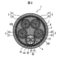
図2は、本実施の形態に係る複合ケーブル1の横断面図である。
FIG. 2 is a cross-sectional view of the
図2に示すように、複合ケーブル1は、電気信号を伝送する少なくとも1本(ここでは1本)の信号線4と、電力供給用の少なくとも1対(ここでは1対)の第1電源線2と、信号線4と第1電源線2とを一括して被覆するシース10と、を備えている。
As shown in FIG. 2, the
本実施の形態では、複合ケーブル1は、EMB用電気モータ11aに接続される1対の第1電源線2と、EMB制御装置11bに接続される信号線4と、を備え、車輪16側と車体14側とを接続するように構成されている。
In the present embodiment, the
第1電源線2は、銅等の良導電性の素線を撚り合わせた中心導体20を、絶縁性の樹脂からなる絶縁体21で被覆した絶縁電線からなる。第1電源線2の中心導体20の外径、および絶縁体21の厚さは、要求される駆動電流の大きさに応じて適宜設定すればよい。
The first
信号線4は、銅等の良導電性の中心導体41を架橋ポリエチレン等の絶縁性の樹脂からなる絶縁体42で被覆して構成され、電気信号を伝送する2本の電線40を有し、これら2本の電線40を撚り合わせたツイストペア線43の周囲に、シールド部材45を設けて構成されている。シールド部材45は、信号線4の最外層に設けられている。なお、ここでは、信号線4がEMBの制御用の信号線である場合を説明するが、車両100の車輪16に搭載されたセンサ用の信号線であってもよい。
The
ツイストペア線43の周囲に直接シールド部材45を設けた場合、シールド部材45が2本の電線40の間の凹部に入り込んでしまい、複合ケーブル1が繰り返し屈曲を受けた際に、シールド部材45の一部に過大な負荷がかかり、シールド部材45が損傷してしまうおそれがある。
When the
そこで、本実施の形態では、ツイストペア線43とシールド部材45との間に介在物44を備えることで、シールド部材45が2本の電線40の間の凹部に入り込むことを抑制し、耐屈曲性を向上させている。介在物44としては、ケーブルの介在物として一般的に用いられるポリプロピレンヤーン、アラミド繊維、ナイロン繊維、あるいは繊維系プラスチック等の繊維状体や、紙もしくは綿糸を用いることができる。
Therefore, in the present embodiment, by providing the
なお、信号線4の具体的な構成はこれに限定されるものではなく、例えば、介在物44を省略してツイストペア線43を絶縁体で被覆し、絶縁体の周囲にシールド部材45を設けるように構成しても構わない。ただし、この場合、製法上、ツイストペア線43の全体を絶縁体で被覆する必要があるため、信号線4の外径が若干大径化してしまう。本実施の形態のように、介在物44を用いた場合、2本の電線40の間の凹部を埋めるように介在物44を配置するだけでよいので、信号線4の外径の大径化を抑制し、複合ケーブル1全体の大径化を抑制することができる。
Note that the specific configuration of the
さて、本実施の形態に係る複合ケーブル1では、信号線4と第1電源線2との間に配置され、信号線4と第1電源線2とを離間させる線状体200をさらに備えている。
By the way, the
本実施形態では、線状体200として、EPB用電気モータ12aに駆動電流を供給する1対の第2電源線3を用いている。第2電源線3は、銅等の良導電性の素線を撚り合わせた中心導体30を、絶縁性の樹脂からなる絶縁体31で被覆した絶縁電線からなる。
In the present embodiment, a pair of second
EPB12は車両の停止中に短時間使用されるのみであり、第2電源線3を流れる駆動電流に起因する電磁波ノイズの影響が比較的小さいため、線状体200として用いることができる。なお、線状体200は第2電源線3に限定されるものではなく、例えば、信号伝送および電力伝送に使用しないダミー線を用いてもよい。なお、ダミー線としては、中心導体に絶縁体を被覆した絶縁電線のみならず、中心導体を省略した樹脂のみからなるものも用いることができる。
The
信号線4と電源線2,3とは、螺旋状に巻き回され、撚り合わされている。なお、信号線4と電源線2,3とを撚り合わせる形態はこれに限定されるものではなく、例えば、撚り方向を周期的に反転させる所謂SZ撚りとしてもよい。
The
本実施の形態では、線状体200の表面、すなわち第2電源線3の絶縁体31が、信号線4のシールド部材45に直接接触することになる。よって、シールド部材45の摩耗を抑制するために、絶縁体31は、なるべく滑りやすい(摩擦係数が小さい)材料で構成されることが望ましい。絶縁体31に用いる材料としては、例えば、ETFE(エチレン−テトラフルオロエチレン共重合体)等のフッ素樹脂が挙げられる。
In the present embodiment, the surface of the
また、信号線4と第2電源線3との間に、摩擦抵抗を低減して潤滑性を高めるための潤滑剤を配置して、シールド部材45の摩耗を抑制するように構成してもよい。潤滑剤としては、例えば、タルク(Mg3Si4O10(OH)2)やシリカ(SiO2)を用いることができる。
Further, a lubricant may be arranged between the
さらにまた、信号線4の周囲に、当該信号線4が周囲の部材に直接接触することを抑制するための第1セパレータ部材(図示せず)を設け、シールド部材45の摩耗を抑制するように構成してもよい。第1セパレータ部材は、例えば、信号線4の外周に紙を巻き付けて構成される。信号線4の外周に巻き付けた紙は、複合ケーブル1の屈曲により細かくちぎれてしまう場合も考えられるが、この細かくちぎれた紙も緩衝材としての役割を果たし、シールド部材45の摩耗の抑制に寄与することになる。
Furthermore, a first separator member (not shown) for suppressing the
複合ケーブル1は、信号線4と第1電源線2と第2電源線3とを一括して被覆する一括シールド部材9をさらに備え、一括シールド部材9の周囲にシース10を被覆するように構成されている。
The
信号線4と電源線2,3の周囲に直接一括シールド部材9を設けた場合、一括シールド部材9と信号線4のシールド部材45とが接触し摩耗が発生してしまう。そこで、本実施の形態では、一括シールド部材9と、信号線4および電源線2,3との間に、一括シールド部材9と信号線4および電源線2,3とを離間させるための第2セパレータ部材8を設けている。第2セパレータ部材8としては、例えば紙を用いることができる。
When the
第2セパレータ部材8の内部には、介在物7が充填されている。介在物7を備えることにより、複合ケーブル1の中心軸に直行する断面におけるシース10の外形を円形状に近づけること、すなわち複合ケーブル1の円形性をより向上させ、複合ケーブル1の配策性をより向上させることが可能になる。
The inside of the
介在物7としては、ケーブルの介在物として一般的に用いられるポリプロピレンヤーン、アラミド繊維、ナイロン繊維、あるいは繊維系プラスチック等の繊維状体や、紙もしくは綿糸を用いることができるが、本実施の形態では、介在物7に人造ポリペプチド繊維を含有させている。この人造ポリペプチド繊維は、クモ(蜘蛛)糸繊維とも呼ばれ、天然クモ糸タンパク質に由来するポリペプチドを主成分として含む人造繊維である。介在物7に人造ポリペプチド繊維を含有させることで、複合ケーブル1の強度を高めることができる。
As the inclusion 7, a fibrous material such as polypropylene yarn, aramid fiber, nylon fiber, or fibrous plastic, or paper or cotton yarn, which is generally used as an inclusion of a cable, can be used. In the above, the inclusion 7 contains an artificial polypeptide fiber. This artificial polypeptide fiber is also called a spider silk fiber, and is an artificial fiber containing a polypeptide derived from a natural spider silk protein as a main component. By including the artificial polypeptide fiber in the inclusion 7, the strength of the
一括シールド部材9としては、例えば、銅等の良導電性の複数の素線を格子状に編み合わせた編組シールドを用いることができる。本実施の形態では、図3に示すように、一括シールド部材9として、銅等の良導電性の複数の素線61と人造ポリペプチド繊維(人工クモ糸繊維)62とを「所定の割合」で共に格子状に混み合わされた人工クモ糸繊維混入編組シールドを用いた。ここで、「所定の割合」とは、本来のシールド機能を失わない程度の割合のことである。一括シールド部材9として人工クモ糸繊維混入編組シールドを用いることで、一括シールド部材9の軽量化を図ることができる。
As the
なお、ここでは、一括シールド部材9として人工クモ糸繊維混入編組シールドを用いる場合について説明したが、これに限らず、例えば、一括シールド部材9を、素線61を格子状に編み込んだ編組シールド層と、人造ポリペプチド繊維62を格子状に編み込んだ人工クモ糸編組層とを積層した積層編組シールドとしてもよい。
Here, the case where an artificial spider yarn fiber-containing braided shield is used as the
シース10としては、柔軟性および耐久性に優れた軟質ポリウレタンからなるものを好適に用いることができる。また、シース10に人造ポリペプチド繊維を含有させてもよい。人造ポリペプチド繊維を含有させることによって強度が高まるため、シース10に人造ポリペプチド繊維を含有させることにより、シース10を薄肉化することが可能になり、複合ケーブル1の強度を保ちながら屈曲性を高めると共に、軽量化を図ることも可能になる。
As the
次に、本実施の形態に係る複合ハーネスについて説明する。 Next, the composite harness according to the present embodiment will be described.
図4は、本実施の形態に係る複合ハーネスの概略構成図である。 FIG. 4 is a schematic configuration diagram of the composite harness according to the present embodiment.
図4に示すように、複合ハーネス60は、本実施の形態に係る複合ケーブル1と、信号線4と電源線2,3の端部のうち、少なくとも何れかの端部に取り付けられたコネクタと、を備えて構成される。
As shown in FIG. 4, the
図4では、図示左側が車輪16側の端部を示し、図示右側が車体14側(中継ボックス18側)の端部を示している。以下の説明では、複合ハーネス60の車輪16側の端部を「一端部」、車体14側(中継ボックス18側)の端部を「他端部」という。
In FIG. 4, the left side in the figure shows the end on the wheel 16 side, and the right side in the figure shows the end on the
1対の第1電源線2の一端部には、EMB用電気モータ11aとの接続のための車輪側第1電源コネクタ61aが取り付けられ、1対の第1電源線2の他端部には、中継ボックス18内における電線群19との接続のための車体側第1電源コネクタ61bが取り付けられている。
A wheel-side first power connector 61a for connection to the EMB
1対の第2電源線3の一端部には、EPB用電気モータ12aとの接続のための車輪側第2電源コネクタ62aが取り付けられ、1対の第2電源線3の他端部には、中継ボックス18内における電線群19との接続のための車体側第2電源コネクタ62bが取り付けられている。
A wheel-side
信号線4の一端部には、EMB制御装置11bとの接続のための車輪側CAN用コネクタ63aが取り付けられ、信号線4の他端部には、中継ボックス18内における電線群19との接続のための車体側CAN用コネクタ63bが取り付けられている。
At one end of the
なお、ここでは、電源線2,3と信号線4に個別にコネクタを設ける場合を説明したが、電源線2,3と信号線4とを一括して接続する専用のコネクタを備えるようにしても構わない。
Here, the case where the connectors are individually provided for the
以上説明したように、本実施の形態に係る複合ケーブル1では、信号線4と第1電源線2との間に、信号線4と第1電源線2とを離間させる線状体200を配置している。
As described above, in the
線状体200を備えることで、第1電源線2と信号線4とを離間させることが可能となり、第1電源線2を流れる電流に起因する電磁波ノイズの影響を低減することが可能になる。その結果、信号線4に大型のシールド部材45を設ける等の対策が不要となるため、信号線4の大径化を抑制し、複合ケーブル1全体の大径化を抑制することが可能になる。すなわち、本実施形態によれば、大径化を抑制しつつも電磁波ノイズの影響を低減することが可能な複合ケーブル1を実現できる。
By providing the
次に、以上説明した実施の形態から把握される技術思想について、実施の形態における符号等を援用して記載する。ただし、以下の記載における各符号は、特許請求の範囲における構成要素を実施の形態に具体的に示した部材等に限定するものではない。 Next, technical ideas grasped from the embodiments described above will be described with reference to the reference numerals and the like in the embodiments. However, each reference numeral in the following description does not limit the constituent elements in the claims to members specifically shown in the embodiments.
[1]電気信号を伝送する少なくとも1本の信号線(4)と、電力供給用の少なくとも1対の第1電源線(2)と、前記信号線(4)と前記第1電源線(2)とを一括して被覆するシース(10)と、前記信号線(4)と前記第1電源線(2)との間に配置され、前記信号線(4)と前記第1電源線(2)とを離間させる線状体(200)と、を備え、前記線状体(200)は、車両の停止後に制動力を発生させる電動パーキングブレーキ(12)の電気モータ(12a)に駆動電流を供給する第2電源線(3)、または、信号伝送および電力伝送に使用しないダミー線からなる、複合ケーブル(1)。 [1] At least one signal line (4) for transmitting an electric signal, at least one pair of first power lines (2) for supplying power, the signal line (4) and the first power line (2) ) Is disposed between the signal line (4) and the first power line (2), and the signal line (4) and the first power line (2). And a linear body (200) that separates the driving current from the electric motor (12a) of the electric parking brake (12) that generates a braking force after the vehicle stops. A composite cable (1) comprising a second power supply line (3) to be supplied or a dummy line not used for signal transmission and power transmission.
[2]前記第1電源線(2)は、電気機械式ブレーキ(11)の電気モータ(11a)に駆動電流を供給する電源線を含み、前記信号線(4)は、前記車両の車輪に搭載されたセンサ用の信号線、または、前記電気機械式ブレーキの制御用の信号線を含む、前記[1]記載の複合ケーブル(1)。 [2] The first power supply line (2) includes a power supply line for supplying a drive current to an electric motor (11a) of the electromechanical brake (11), and the signal line (4) is connected to a wheel of the vehicle. The composite cable (1) according to [1], further including a signal line for a mounted sensor or a signal line for controlling the electromechanical brake.
[3]前記信号線(4)は、最外層にシールド部材(45)を備え、前記信号線(4)の周囲に、当該信号線が周囲の部材に直接接触することを抑制するための第1セパレータ部材を設けた、前記[1]または[2]記載の複合ケーブル(1)。 [3] The signal line (4) includes a shield member (45) on the outermost layer, and is provided around the signal line (4) to prevent the signal line from directly contacting surrounding members. The composite cable (1) according to the above [1] or [2], further comprising one separator member.
[4]前記信号線(4)と前記第1電源線(2)とを一括して被覆する一括シールド部材(9)を備え、前記一括シールド部材(9)の周囲に前記シース(10)を被覆するように構成され、前記一括シールド部材(9)と、前記信号線(4)および前記第1電源線(2)との間に、前記一括シールド部材(9)と前記信号線(4)および前記第1電源線(2)とを離間させるための第2セパレータ部材(8)を設けた、前記[1]乃至[3]いずれかに記載の複合ケーブル(1)。 [4] A collective shield member (9) for collectively covering the signal line (4) and the first power supply line (2) is provided, and the sheath (10) is provided around the collective shield member (9). The collective shield member (9) and the signal line (4) are configured to cover between the collective shield member (9) and the signal line (4) and the first power supply line (2). The composite cable (1) according to any of [1] to [3], further comprising a second separator member (8) for separating the first power supply line (2) from the first power supply line (2).
[5]前記信号線(4)は、電気信号を伝送する2本の電線(40)を撚り合わせたツイストペア線(43)と、前記ツイストペア線(43)の周囲に設けられた前記シールド部材(45)と、前記ツイストペア線(43)と前記シールド部材(45)との間に設けられた介在物(44)と、を備える、前記[1]乃至[4]いずれかに記載の複合ケーブル(1)。 [5] The signal line (4) includes a twisted pair wire (43) formed by twisting two electric wires (40) that transmit an electric signal, and the shield member (43) provided around the twisted pair wire (43). 45) and an interposition (44) provided between the twisted pair wire (43) and the shield member (45). The composite cable according to any one of [1] to [4], 1).
[6]前記[1]乃至[5]いずれかに記載の複合ケーブル(1)と、前記信号線(4)と前記第1電源線(2)の端部のうち、少なくとも何れかの端部に取り付けられたコネクタと、を備えた、複合ハーネス(60)。 [6] At least one of the ends of the composite cable (1) according to any one of [1] to [5], the signal line (4), and the first power supply line (2). And a connector attached to the composite harness (60).
以上、本発明の実施の形態を説明したが、上記の実施の形態は特許請求の範囲に係る発明を限定するものではない。また、実施の形態の中で説明した特徴の組合せの全てが発明の課題を解決するための手段に必須であるとは限らない点に留意すべきである。 The embodiments of the present invention have been described above, but the above embodiments do not limit the invention according to the claims. Also, it should be noted that not all combinations of the features described in the embodiments are necessarily indispensable to the means for solving the problems of the invention.
また、本発明は、その趣旨を逸脱しない範囲で適宜変形して実施することが可能である。 Further, the present invention can be appropriately modified and implemented without departing from the spirit thereof.
例えば、上記実施の形態では、信号線4がEMB制御用のCANケーブルである場合を説明したが、信号線4の用途はこれに限定されるものではなく、例えば、信号線4は、車輪16に設けられたタイヤの空気圧を検出する空気圧センサ用、走行中の車輪の回転速度を検出するABS(Anti-lock Brake System)センサ用、温度センサ用の信号線、あるいは車両100の制振装置の制御に用いられるダンパ線であってもよい。
For example, in the above embodiment, the case where the
また、信号線4の本数も1本に限定されず、2本以上であってもよい。2本以上の信号線4を備える場合で、かつ、信号線4同士が隣接して配置される場合には、複合ケーブル1の屈曲時におけるシールド部材45の摩耗を抑制するために、各信号線4の周囲にそれぞれ第1セパレータ部材を設けることが望ましい。
Further, the number of
また、第1電源線2の用途についても、EMB用電気モータ11aの給電用に限定されるものではなく、例えば、車輪16に搭載されたインホイルモータに駆動電流を供給するものであってもよい。さらには、EPB用電気モータ12aの給電用の電源線(第2電源線3)を第1電源線2に含めてもよい。この場合、線状体200として、樹脂からなる線状体や、ダミー線等を用いることになる。第1電源線2の対数は1対に限らず、2対以上であってもよい。また、線状体200の本数についても、1本であってもよいし、3本以上であってもよい。
Further, the use of the first
また、上記実施の形態では、信号線4にシールド部材45を備える場合を説明したが、第1電源線2と信号線4との離間により、第1電源線2を流れる電流に起因する電磁波ノイズの信号線4への影響が十分に小さい場合には、シールド部材45を省略してもよい。
In the above-described embodiment, the case where the
また、上記実施の形態では、一括シールド部材9を設ける場合について説明したが、一括シールド部材9およびセパレータ部材8は省略可能である。この場合、介在物7を省略して、充実のシース10を設けるようにしてもよい。
Further, in the above embodiment, the case where the
さらに、上記実施の形態では言及しなかったが、シールド部材45を有さない信号線をさらに備えてもよい。この場合、図5に示す複合ケーブル80のように、頻繁に駆動電流を流す第1電源線2と隣接しない位置に、信号線81,82を配置することが好ましい。より具体的には、線状体200の第1電源線2と反対側の領域(信号線4側の領域)に、信号線81,82を配置することが望ましい。図5では、一例として、線状体200である第2電源線3と信号線4とセパレータ部材8とに囲まれた領域に、信号線81,82を配置した場合を示している。
Further, although not described in the above embodiment, a signal line having no
1…複合ケーブル
2…第1電源線
3…第2電源線
4…信号線
7…介在物
8…第2セパレータ部材
9…一括シールド部材
10…シース
45…シールド部材
200…線状体
DESCRIPTION OF
Claims (7)
それぞれ中心導体と当該中心導体を被覆する絶縁体とを有する絶縁電線であり車両の走行中に駆動電流を供給する2本の第1電源線と、
それぞれ中心導体と当該中心導体を被覆する絶縁体とを有する絶縁電線であり前記車両の停止後に制動力を発生させる電動パーキングブレーキの電気モータに駆動電流を供給する電動パーキングブレーキ用の2本の第2電源線と、
前記車両の走行中の車輪の回転速度を検出するABS(Anti−lock Brake System)センサ用であり、それぞれ中心導体と当該中心導体を被覆する絶縁体とを有する2本の電線が撚り合わされて構成され電気信号を伝送する1本の信号線と、
前記2本の第1電源線と前記2本の第2電源線と前記信号線とを一括して被覆するシースと、
を備え、
前記2本の第2電源線は、前記信号線と前記2本の第1電源線との間に配置され、前記信号線と前記2本の第1電源線とを離間させており、
前記電線の外径は、前記第2電源線の外径よりも小さく、前記第1電源線の外径及び前記信号線の外径は、前記2本の第2電源線間の距離よりも大きい
複合ケーブル。 A composite cable wired from the vehicle body side to the wheel side,
Two first power lines, each of which is an insulated wire having a center conductor and an insulator covering the center conductor and supplying a drive current while the vehicle is traveling;
Two electric parking brakes, each of which is an insulated wire having a center conductor and an insulator covering the center conductor and which supplies a drive current to an electric motor of the electric parking brake which generates a braking force after the vehicle stops. Two power lines,
It is for an ABS (Anti-Lock Break System) sensor for detecting a rotation speed of a wheel while the vehicle is traveling, and is configured by twisting two electric wires each having a center conductor and an insulator covering the center conductor. One signal line for transmitting an electric signal;
A sheath that collectively covers the two first power lines, the two second power lines, and the signal lines;
With
The two second power supply lines are arranged between the signal line and the two first power supply lines, and separate the signal line and the two first power supply lines;
An outer diameter of the electric wire is smaller than an outer diameter of the second power line, and an outer diameter of the first power line and an outer diameter of the signal line are larger than a distance between the two second power lines. Composite cable.
前記信号線の一部は、前記2本の第2電源線間に入り込んでいる、
請求項1記載の複合ケーブル。 An interval between the two second power lines is wider than an interval between the two first power lines;
A part of the signal line enters between the two second power supply lines;
The composite cable according to claim 1.
前記2本の第1電源線のそれぞれの外径は、前記2本の電線のそれぞれの外径よりも大きい、
請求項1または2記載の複合ケーブル。 The two first power lines are power lines for an electromechanical brake that supplies a drive current to an electric motor of the electromechanical brake during traveling of the vehicle,
The outer diameter of each of the two first power lines is larger than the outer diameter of each of the two electric wires,
The composite cable according to claim 1.
請求項1〜3いずれかに記載の複合ケーブル。 The signal line, the two first power lines, and the two second power lines between the signal line, the two first power lines, and the two second power lines and the sheath. A second separator member for separating the wire and the sheath was provided,
The composite cable according to claim 1.
電気信号を伝送する2本の電線を撚り合わせたツイストペア線と、
前記ツイストペア線の周囲に設けられたシールド部材と、
前記ツイストペア線と前記シールド部材との間に設けられた介在物と、を備える、
請求項3に記載の複合ケーブル。 The signal line is
A twisted pair wire in which two electric wires that transmit an electric signal are twisted,
A shield member provided around the twisted pair wire,
And an intervening body provided between the twisted pair wire and the shield member.
The composite cable according to claim 3.
前記信号線と前記第1電源線の端部のうち、少なくとも何れかの端部に取り付けられたコネクタと、を備えた、
複合ハーネス。 A composite cable according to any one of claims 1 to 5,
A connector attached to at least one end of the signal line and the end of the first power supply line,
Composite harness.
車両。 The wheel side and the vehicle body side were connected using the composite cable according to any one of claims 1 to 5,
vehicle.
Priority Applications (1)
| Application Number | Priority Date | Filing Date | Title |
|---|---|---|---|
| JP2018173234A JP6638784B2 (en) | 2018-09-18 | 2018-09-18 | Composite cable, composite harness, and vehicle |
Applications Claiming Priority (1)
| Application Number | Priority Date | Filing Date | Title |
|---|---|---|---|
| JP2018173234A JP6638784B2 (en) | 2018-09-18 | 2018-09-18 | Composite cable, composite harness, and vehicle |
Related Parent Applications (1)
| Application Number | Title | Priority Date | Filing Date |
|---|---|---|---|
| JP2017507210A Division JP6493708B2 (en) | 2015-03-24 | 2015-03-24 | Composite cable, composite harness, and vehicle |
Related Child Applications (1)
| Application Number | Title | Priority Date | Filing Date |
|---|---|---|---|
| JP2019224971A Division JP6876259B2 (en) | 2019-12-13 | 2019-12-13 | Composite cables, composite harnesses, and vehicles |
Publications (3)
| Publication Number | Publication Date |
|---|---|
| JP2018200894A JP2018200894A (en) | 2018-12-20 |
| JP2018200894A5 JP2018200894A5 (en) | 2019-02-07 |
| JP6638784B2 true JP6638784B2 (en) | 2020-01-29 |
Family
ID=64667348
Family Applications (1)
| Application Number | Title | Priority Date | Filing Date |
|---|---|---|---|
| JP2018173234A Active JP6638784B2 (en) | 2018-09-18 | 2018-09-18 | Composite cable, composite harness, and vehicle |
Country Status (1)
| Country | Link |
|---|---|
| JP (1) | JP6638784B2 (en) |
Family Cites Families (6)
| Publication number | Priority date | Publication date | Assignee | Title |
|---|---|---|---|---|
| JP3871886B2 (en) * | 2001-01-19 | 2007-01-24 | 沖電線株式会社 | Broadband shielded composite cable |
| JP2007026736A (en) * | 2005-07-13 | 2007-02-01 | Hitachi Cable Ltd | Bending resistant cable |
| JPWO2012105142A1 (en) * | 2011-01-31 | 2014-07-03 | オリンパスメディカルシステムズ株式会社 | Endoscope signal cable |
| JP2013122825A (en) * | 2011-12-09 | 2013-06-20 | Sumitomo Electric Ind Ltd | Active cable |
| JP5541331B2 (en) * | 2012-04-20 | 2014-07-09 | 日立金属株式会社 | Composite harness |
| JP6219263B2 (en) * | 2014-12-22 | 2017-10-25 | 日立金属株式会社 | Composite cable for vehicle and composite harness for vehicle |
-
2018
- 2018-09-18 JP JP2018173234A patent/JP6638784B2/en active Active
Also Published As
| Publication number | Publication date |
|---|---|
| JP2018200894A (en) | 2018-12-20 |
Similar Documents
| Publication | Publication Date | Title |
|---|---|---|
| JP6493707B2 (en) | Composite cable, composite harness, and vehicle | |
| JP6822770B2 (en) | Composite cable and composite harness | |
| JP5943170B1 (en) | Composite cable and composite harness | |
| JP5943171B1 (en) | Composite cable and composite harness | |
| US10569724B2 (en) | Composite cable and wire harness | |
| JP6493708B2 (en) | Composite cable, composite harness, and vehicle | |
| JP2017188200A (en) | Complex cable and complex harness | |
| JP6424950B2 (en) | Composite cable, composite harness, and vehicle | |
| JP2017059318A (en) | Composite cable and composite harness | |
| JP6804858B2 (en) | Composite cable and composite harness | |
| JP6638784B2 (en) | Composite cable, composite harness, and vehicle | |
| JP7111236B2 (en) | Composite cable and composite harness | |
| JP6876259B2 (en) | Composite cables, composite harnesses, and vehicles | |
| JP7219876B2 (en) | Composite cable and wire harness | |
| JP7096989B2 (en) | Composite cable and composite harness | |
| JP2020092046A (en) | Composite cable and composite harness | |
| JP2017059319A (en) | Composite cable and composite harness | |
| JP7096988B2 (en) | Composite cable and composite harness | |
| JP6222532B2 (en) | Composite cable and composite harness | |
| JP6183730B2 (en) | Composite cable and composite harness | |
| JP2022050662A (en) | Cable and harness |
Legal Events
| Date | Code | Title | Description |
|---|---|---|---|
| A621 | Written request for application examination |
Free format text: JAPANESE INTERMEDIATE CODE: A621 Effective date: 20180918 |
|
| A521 | Request for written amendment filed |
Free format text: JAPANESE INTERMEDIATE CODE: A523 Effective date: 20181207 |
|
| A871 | Explanation of circumstances concerning accelerated examination |
Free format text: JAPANESE INTERMEDIATE CODE: A871 Effective date: 20181207 |
|
| A975 | Report on accelerated examination |
Free format text: JAPANESE INTERMEDIATE CODE: A971005 Effective date: 20181228 |
|
| A131 | Notification of reasons for refusal |
Free format text: JAPANESE INTERMEDIATE CODE: A131 Effective date: 20190201 |
|
| RD02 | Notification of acceptance of power of attorney |
Free format text: JAPANESE INTERMEDIATE CODE: A7422 Effective date: 20190320 |
|
| A521 | Request for written amendment filed |
Free format text: JAPANESE INTERMEDIATE CODE: A523 Effective date: 20190329 |
|
| A131 | Notification of reasons for refusal |
Free format text: JAPANESE INTERMEDIATE CODE: A131 Effective date: 20190625 |
|
| A521 | Request for written amendment filed |
Free format text: JAPANESE INTERMEDIATE CODE: A523 Effective date: 20190823 |
|
| TRDD | Decision of grant or rejection written | ||
| A01 | Written decision to grant a patent or to grant a registration (utility model) |
Free format text: JAPANESE INTERMEDIATE CODE: A01 Effective date: 20191126 |
|
| A61 | First payment of annual fees (during grant procedure) |
Free format text: JAPANESE INTERMEDIATE CODE: A61 Effective date: 20191209 |
|
| R150 | Certificate of patent or registration of utility model |
Ref document number: 6638784 Country of ref document: JP Free format text: JAPANESE INTERMEDIATE CODE: R150 |
|
| S531 | Written request for registration of change of domicile |
Free format text: JAPANESE INTERMEDIATE CODE: R313531 |
|
| S533 | Written request for registration of change of name |
Free format text: JAPANESE INTERMEDIATE CODE: R313533 |
|
| R350 | Written notification of registration of transfer |
Free format text: JAPANESE INTERMEDIATE CODE: R350 |