JP6637012B2 - Semiconductor device - Google Patents
Semiconductor device Download PDFInfo
- Publication number
- JP6637012B2 JP6637012B2 JP2017202112A JP2017202112A JP6637012B2 JP 6637012 B2 JP6637012 B2 JP 6637012B2 JP 2017202112 A JP2017202112 A JP 2017202112A JP 2017202112 A JP2017202112 A JP 2017202112A JP 6637012 B2 JP6637012 B2 JP 6637012B2
- Authority
- JP
- Japan
- Prior art keywords
- region
- type
- semiconductor device
- opening
- layer
- Prior art date
- Legal status (The legal status is an assumption and is not a legal conclusion. Google has not performed a legal analysis and makes no representation as to the accuracy of the status listed.)
- Active
Links
- 239000004065 semiconductor Substances 0.000 title claims description 239
- 239000012535 impurity Substances 0.000 claims description 220
- 239000010410 layer Substances 0.000 claims description 215
- 239000002344 surface layer Substances 0.000 claims description 26
- 238000011084 recovery Methods 0.000 claims description 11
- 239000000758 substrate Substances 0.000 claims description 11
- 239000002356 single layer Substances 0.000 claims description 8
- 239000005360 phosphosilicate glass Substances 0.000 claims description 7
- 229910004298 SiO 2 Inorganic materials 0.000 claims description 6
- 238000009413 insulation Methods 0.000 claims description 3
- 239000010408 film Substances 0.000 description 54
- 108091006146 Channels Proteins 0.000 description 26
- 230000015572 biosynthetic process Effects 0.000 description 16
- 230000002093 peripheral effect Effects 0.000 description 16
- 238000010586 diagram Methods 0.000 description 8
- 230000015556 catabolic process Effects 0.000 description 6
- 230000001681 protective effect Effects 0.000 description 6
- 241000293849 Cordylanthus Species 0.000 description 5
- 230000000694 effects Effects 0.000 description 5
- 238000002955 isolation Methods 0.000 description 5
- 230000002040 relaxant effect Effects 0.000 description 5
- XUIMIQQOPSSXEZ-UHFFFAOYSA-N Silicon Chemical compound [Si] XUIMIQQOPSSXEZ-UHFFFAOYSA-N 0.000 description 4
- 229910045601 alloy Inorganic materials 0.000 description 4
- 239000000956 alloy Substances 0.000 description 4
- 239000011810 insulating material Substances 0.000 description 4
- 229910052710 silicon Inorganic materials 0.000 description 4
- 239000010703 silicon Substances 0.000 description 4
- 229910052782 aluminium Inorganic materials 0.000 description 3
- XAGFODPZIPBFFR-UHFFFAOYSA-N aluminium Chemical compound [Al] XAGFODPZIPBFFR-UHFFFAOYSA-N 0.000 description 3
- 230000012447 hatching Effects 0.000 description 3
- 239000012212 insulator Substances 0.000 description 3
- RYGMFSIKBFXOCR-UHFFFAOYSA-N Copper Chemical compound [Cu] RYGMFSIKBFXOCR-UHFFFAOYSA-N 0.000 description 2
- 108010075750 P-Type Calcium Channels Proteins 0.000 description 2
- 229910052802 copper Inorganic materials 0.000 description 2
- 239000010949 copper Substances 0.000 description 2
- 238000000034 method Methods 0.000 description 2
- 238000004088 simulation Methods 0.000 description 2
- 229910000789 Aluminium-silicon alloy Inorganic materials 0.000 description 1
- 229910000676 Si alloy Inorganic materials 0.000 description 1
- CSDREXVUYHZDNP-UHFFFAOYSA-N alumanylidynesilicon Chemical compound [Al].[Si] CSDREXVUYHZDNP-UHFFFAOYSA-N 0.000 description 1
- 238000005229 chemical vapour deposition Methods 0.000 description 1
- 239000003822 epoxy resin Substances 0.000 description 1
- 238000005530 etching Methods 0.000 description 1
- 230000005669 field effect Effects 0.000 description 1
- 229910052751 metal Inorganic materials 0.000 description 1
- 239000002184 metal Substances 0.000 description 1
- 230000003647 oxidation Effects 0.000 description 1
- 238000007254 oxidation reaction Methods 0.000 description 1
- 230000001590 oxidative effect Effects 0.000 description 1
- 238000000206 photolithography Methods 0.000 description 1
- 229920000647 polyepoxide Polymers 0.000 description 1
- 229920001721 polyimide Polymers 0.000 description 1
- 239000009719 polyimide resin Substances 0.000 description 1
- 239000010409 thin film Substances 0.000 description 1
Images


Classifications
-
- H—ELECTRICITY
- H01—ELECTRIC ELEMENTS
- H01L—SEMICONDUCTOR DEVICES NOT COVERED BY CLASS H10
- H01L29/00—Semiconductor devices adapted for rectifying, amplifying, oscillating or switching, or capacitors or resistors with at least one potential-jump barrier or surface barrier, e.g. PN junction depletion layer or carrier concentration layer; Details of semiconductor bodies or of electrodes thereof ; Multistep manufacturing processes therefor
- H01L29/02—Semiconductor bodies ; Multistep manufacturing processes therefor
- H01L29/06—Semiconductor bodies ; Multistep manufacturing processes therefor characterised by their shape; characterised by the shapes, relative sizes, or dispositions of the semiconductor regions ; characterised by the concentration or distribution of impurities within semiconductor regions
- H01L29/0603—Semiconductor bodies ; Multistep manufacturing processes therefor characterised by their shape; characterised by the shapes, relative sizes, or dispositions of the semiconductor regions ; characterised by the concentration or distribution of impurities within semiconductor regions characterised by particular constructional design considerations, e.g. for preventing surface leakage, for controlling electric field concentration or for internal isolations regions
- H01L29/0607—Semiconductor bodies ; Multistep manufacturing processes therefor characterised by their shape; characterised by the shapes, relative sizes, or dispositions of the semiconductor regions ; characterised by the concentration or distribution of impurities within semiconductor regions characterised by particular constructional design considerations, e.g. for preventing surface leakage, for controlling electric field concentration or for internal isolations regions for preventing surface leakage or controlling electric field concentration
- H01L29/0611—Semiconductor bodies ; Multistep manufacturing processes therefor characterised by their shape; characterised by the shapes, relative sizes, or dispositions of the semiconductor regions ; characterised by the concentration or distribution of impurities within semiconductor regions characterised by particular constructional design considerations, e.g. for preventing surface leakage, for controlling electric field concentration or for internal isolations regions for preventing surface leakage or controlling electric field concentration for increasing or controlling the breakdown voltage of reverse biased devices
- H01L29/0615—Semiconductor bodies ; Multistep manufacturing processes therefor characterised by their shape; characterised by the shapes, relative sizes, or dispositions of the semiconductor regions ; characterised by the concentration or distribution of impurities within semiconductor regions characterised by particular constructional design considerations, e.g. for preventing surface leakage, for controlling electric field concentration or for internal isolations regions for preventing surface leakage or controlling electric field concentration for increasing or controlling the breakdown voltage of reverse biased devices by the doping profile or the shape or the arrangement of the PN junction, or with supplementary regions, e.g. junction termination extension [JTE]
- H01L29/063—Reduced surface field [RESURF] pn-junction structures
- H01L29/0634—Multiple reduced surface field (multi-RESURF) structures, e.g. double RESURF, charge compensation, cool, superjunction (SJ), 3D-RESURF, composite buffer (CB) structures
-
- H—ELECTRICITY
- H01—ELECTRIC ELEMENTS
- H01L—SEMICONDUCTOR DEVICES NOT COVERED BY CLASS H10
- H01L29/00—Semiconductor devices adapted for rectifying, amplifying, oscillating or switching, or capacitors or resistors with at least one potential-jump barrier or surface barrier, e.g. PN junction depletion layer or carrier concentration layer; Details of semiconductor bodies or of electrodes thereof ; Multistep manufacturing processes therefor
- H01L29/66—Types of semiconductor device ; Multistep manufacturing processes therefor
- H01L29/86—Types of semiconductor device ; Multistep manufacturing processes therefor controllable only by variation of the electric current supplied, or only the electric potential applied, to one or more of the electrodes carrying the current to be rectified, amplified, oscillated or switched
- H01L29/861—Diodes
- H01L29/8611—Planar PN junction diodes
-
- H—ELECTRICITY
- H01—ELECTRIC ELEMENTS
- H01L—SEMICONDUCTOR DEVICES NOT COVERED BY CLASS H10
- H01L27/00—Devices consisting of a plurality of semiconductor or other solid-state components formed in or on a common substrate
- H01L27/02—Devices consisting of a plurality of semiconductor or other solid-state components formed in or on a common substrate including semiconductor components specially adapted for rectifying, oscillating, amplifying or switching and having at least one potential-jump barrier or surface barrier; including integrated passive circuit elements with at least one potential-jump barrier or surface barrier
- H01L27/04—Devices consisting of a plurality of semiconductor or other solid-state components formed in or on a common substrate including semiconductor components specially adapted for rectifying, oscillating, amplifying or switching and having at least one potential-jump barrier or surface barrier; including integrated passive circuit elements with at least one potential-jump barrier or surface barrier the substrate being a semiconductor body
- H01L27/06—Devices consisting of a plurality of semiconductor or other solid-state components formed in or on a common substrate including semiconductor components specially adapted for rectifying, oscillating, amplifying or switching and having at least one potential-jump barrier or surface barrier; including integrated passive circuit elements with at least one potential-jump barrier or surface barrier the substrate being a semiconductor body including a plurality of individual components in a non-repetitive configuration
- H01L27/0611—Devices consisting of a plurality of semiconductor or other solid-state components formed in or on a common substrate including semiconductor components specially adapted for rectifying, oscillating, amplifying or switching and having at least one potential-jump barrier or surface barrier; including integrated passive circuit elements with at least one potential-jump barrier or surface barrier the substrate being a semiconductor body including a plurality of individual components in a non-repetitive configuration integrated circuits having a two-dimensional layout of components without a common active region
- H01L27/0617—Devices consisting of a plurality of semiconductor or other solid-state components formed in or on a common substrate including semiconductor components specially adapted for rectifying, oscillating, amplifying or switching and having at least one potential-jump barrier or surface barrier; including integrated passive circuit elements with at least one potential-jump barrier or surface barrier the substrate being a semiconductor body including a plurality of individual components in a non-repetitive configuration integrated circuits having a two-dimensional layout of components without a common active region comprising components of the field-effect type
- H01L27/0629—Devices consisting of a plurality of semiconductor or other solid-state components formed in or on a common substrate including semiconductor components specially adapted for rectifying, oscillating, amplifying or switching and having at least one potential-jump barrier or surface barrier; including integrated passive circuit elements with at least one potential-jump barrier or surface barrier the substrate being a semiconductor body including a plurality of individual components in a non-repetitive configuration integrated circuits having a two-dimensional layout of components without a common active region comprising components of the field-effect type in combination with diodes, or resistors, or capacitors
-
- H—ELECTRICITY
- H01—ELECTRIC ELEMENTS
- H01L—SEMICONDUCTOR DEVICES NOT COVERED BY CLASS H10
- H01L27/00—Devices consisting of a plurality of semiconductor or other solid-state components formed in or on a common substrate
- H01L27/02—Devices consisting of a plurality of semiconductor or other solid-state components formed in or on a common substrate including semiconductor components specially adapted for rectifying, oscillating, amplifying or switching and having at least one potential-jump barrier or surface barrier; including integrated passive circuit elements with at least one potential-jump barrier or surface barrier
- H01L27/04—Devices consisting of a plurality of semiconductor or other solid-state components formed in or on a common substrate including semiconductor components specially adapted for rectifying, oscillating, amplifying or switching and having at least one potential-jump barrier or surface barrier; including integrated passive circuit elements with at least one potential-jump barrier or surface barrier the substrate being a semiconductor body
- H01L27/06—Devices consisting of a plurality of semiconductor or other solid-state components formed in or on a common substrate including semiconductor components specially adapted for rectifying, oscillating, amplifying or switching and having at least one potential-jump barrier or surface barrier; including integrated passive circuit elements with at least one potential-jump barrier or surface barrier the substrate being a semiconductor body including a plurality of individual components in a non-repetitive configuration
- H01L27/0611—Devices consisting of a plurality of semiconductor or other solid-state components formed in or on a common substrate including semiconductor components specially adapted for rectifying, oscillating, amplifying or switching and having at least one potential-jump barrier or surface barrier; including integrated passive circuit elements with at least one potential-jump barrier or surface barrier the substrate being a semiconductor body including a plurality of individual components in a non-repetitive configuration integrated circuits having a two-dimensional layout of components without a common active region
- H01L27/0617—Devices consisting of a plurality of semiconductor or other solid-state components formed in or on a common substrate including semiconductor components specially adapted for rectifying, oscillating, amplifying or switching and having at least one potential-jump barrier or surface barrier; including integrated passive circuit elements with at least one potential-jump barrier or surface barrier the substrate being a semiconductor body including a plurality of individual components in a non-repetitive configuration integrated circuits having a two-dimensional layout of components without a common active region comprising components of the field-effect type
- H01L27/0635—Devices consisting of a plurality of semiconductor or other solid-state components formed in or on a common substrate including semiconductor components specially adapted for rectifying, oscillating, amplifying or switching and having at least one potential-jump barrier or surface barrier; including integrated passive circuit elements with at least one potential-jump barrier or surface barrier the substrate being a semiconductor body including a plurality of individual components in a non-repetitive configuration integrated circuits having a two-dimensional layout of components without a common active region comprising components of the field-effect type in combination with bipolar transistors and diodes, or resistors, or capacitors
-
- H—ELECTRICITY
- H01—ELECTRIC ELEMENTS
- H01L—SEMICONDUCTOR DEVICES NOT COVERED BY CLASS H10
- H01L29/00—Semiconductor devices adapted for rectifying, amplifying, oscillating or switching, or capacitors or resistors with at least one potential-jump barrier or surface barrier, e.g. PN junction depletion layer or carrier concentration layer; Details of semiconductor bodies or of electrodes thereof ; Multistep manufacturing processes therefor
- H01L29/02—Semiconductor bodies ; Multistep manufacturing processes therefor
- H01L29/06—Semiconductor bodies ; Multistep manufacturing processes therefor characterised by their shape; characterised by the shapes, relative sizes, or dispositions of the semiconductor regions ; characterised by the concentration or distribution of impurities within semiconductor regions
- H01L29/0603—Semiconductor bodies ; Multistep manufacturing processes therefor characterised by their shape; characterised by the shapes, relative sizes, or dispositions of the semiconductor regions ; characterised by the concentration or distribution of impurities within semiconductor regions characterised by particular constructional design considerations, e.g. for preventing surface leakage, for controlling electric field concentration or for internal isolations regions
- H01L29/0607—Semiconductor bodies ; Multistep manufacturing processes therefor characterised by their shape; characterised by the shapes, relative sizes, or dispositions of the semiconductor regions ; characterised by the concentration or distribution of impurities within semiconductor regions characterised by particular constructional design considerations, e.g. for preventing surface leakage, for controlling electric field concentration or for internal isolations regions for preventing surface leakage or controlling electric field concentration
- H01L29/0611—Semiconductor bodies ; Multistep manufacturing processes therefor characterised by their shape; characterised by the shapes, relative sizes, or dispositions of the semiconductor regions ; characterised by the concentration or distribution of impurities within semiconductor regions characterised by particular constructional design considerations, e.g. for preventing surface leakage, for controlling electric field concentration or for internal isolations regions for preventing surface leakage or controlling electric field concentration for increasing or controlling the breakdown voltage of reverse biased devices
- H01L29/0615—Semiconductor bodies ; Multistep manufacturing processes therefor characterised by their shape; characterised by the shapes, relative sizes, or dispositions of the semiconductor regions ; characterised by the concentration or distribution of impurities within semiconductor regions characterised by particular constructional design considerations, e.g. for preventing surface leakage, for controlling electric field concentration or for internal isolations regions for preventing surface leakage or controlling electric field concentration for increasing or controlling the breakdown voltage of reverse biased devices by the doping profile or the shape or the arrangement of the PN junction, or with supplementary regions, e.g. junction termination extension [JTE]
- H01L29/0619—Semiconductor bodies ; Multistep manufacturing processes therefor characterised by their shape; characterised by the shapes, relative sizes, or dispositions of the semiconductor regions ; characterised by the concentration or distribution of impurities within semiconductor regions characterised by particular constructional design considerations, e.g. for preventing surface leakage, for controlling electric field concentration or for internal isolations regions for preventing surface leakage or controlling electric field concentration for increasing or controlling the breakdown voltage of reverse biased devices by the doping profile or the shape or the arrangement of the PN junction, or with supplementary regions, e.g. junction termination extension [JTE] with a supplementary region doped oppositely to or in rectifying contact with the semiconductor containing or contacting region, e.g. guard rings with PN or Schottky junction
-
- H—ELECTRICITY
- H01—ELECTRIC ELEMENTS
- H01L—SEMICONDUCTOR DEVICES NOT COVERED BY CLASS H10
- H01L29/00—Semiconductor devices adapted for rectifying, amplifying, oscillating or switching, or capacitors or resistors with at least one potential-jump barrier or surface barrier, e.g. PN junction depletion layer or carrier concentration layer; Details of semiconductor bodies or of electrodes thereof ; Multistep manufacturing processes therefor
- H01L29/02—Semiconductor bodies ; Multistep manufacturing processes therefor
- H01L29/06—Semiconductor bodies ; Multistep manufacturing processes therefor characterised by their shape; characterised by the shapes, relative sizes, or dispositions of the semiconductor regions ; characterised by the concentration or distribution of impurities within semiconductor regions
- H01L29/08—Semiconductor bodies ; Multistep manufacturing processes therefor characterised by their shape; characterised by the shapes, relative sizes, or dispositions of the semiconductor regions ; characterised by the concentration or distribution of impurities within semiconductor regions with semiconductor regions connected to an electrode carrying current to be rectified, amplified or switched and such electrode being part of a semiconductor device which comprises three or more electrodes
- H01L29/0804—Emitter regions of bipolar transistors
-
- H—ELECTRICITY
- H01—ELECTRIC ELEMENTS
- H01L—SEMICONDUCTOR DEVICES NOT COVERED BY CLASS H10
- H01L29/00—Semiconductor devices adapted for rectifying, amplifying, oscillating or switching, or capacitors or resistors with at least one potential-jump barrier or surface barrier, e.g. PN junction depletion layer or carrier concentration layer; Details of semiconductor bodies or of electrodes thereof ; Multistep manufacturing processes therefor
- H01L29/02—Semiconductor bodies ; Multistep manufacturing processes therefor
- H01L29/06—Semiconductor bodies ; Multistep manufacturing processes therefor characterised by their shape; characterised by the shapes, relative sizes, or dispositions of the semiconductor regions ; characterised by the concentration or distribution of impurities within semiconductor regions
- H01L29/08—Semiconductor bodies ; Multistep manufacturing processes therefor characterised by their shape; characterised by the shapes, relative sizes, or dispositions of the semiconductor regions ; characterised by the concentration or distribution of impurities within semiconductor regions with semiconductor regions connected to an electrode carrying current to be rectified, amplified or switched and such electrode being part of a semiconductor device which comprises three or more electrodes
- H01L29/0821—Collector regions of bipolar transistors
-
- H—ELECTRICITY
- H01—ELECTRIC ELEMENTS
- H01L—SEMICONDUCTOR DEVICES NOT COVERED BY CLASS H10
- H01L29/00—Semiconductor devices adapted for rectifying, amplifying, oscillating or switching, or capacitors or resistors with at least one potential-jump barrier or surface barrier, e.g. PN junction depletion layer or carrier concentration layer; Details of semiconductor bodies or of electrodes thereof ; Multistep manufacturing processes therefor
- H01L29/02—Semiconductor bodies ; Multistep manufacturing processes therefor
- H01L29/06—Semiconductor bodies ; Multistep manufacturing processes therefor characterised by their shape; characterised by the shapes, relative sizes, or dispositions of the semiconductor regions ; characterised by the concentration or distribution of impurities within semiconductor regions
- H01L29/08—Semiconductor bodies ; Multistep manufacturing processes therefor characterised by their shape; characterised by the shapes, relative sizes, or dispositions of the semiconductor regions ; characterised by the concentration or distribution of impurities within semiconductor regions with semiconductor regions connected to an electrode carrying current to be rectified, amplified or switched and such electrode being part of a semiconductor device which comprises three or more electrodes
- H01L29/0843—Source or drain regions of field-effect devices
- H01L29/0847—Source or drain regions of field-effect devices of field-effect transistors with insulated gate
- H01L29/0852—Source or drain regions of field-effect devices of field-effect transistors with insulated gate of DMOS transistors
- H01L29/0856—Source regions
- H01L29/0865—Disposition
-
- H—ELECTRICITY
- H01—ELECTRIC ELEMENTS
- H01L—SEMICONDUCTOR DEVICES NOT COVERED BY CLASS H10
- H01L29/00—Semiconductor devices adapted for rectifying, amplifying, oscillating or switching, or capacitors or resistors with at least one potential-jump barrier or surface barrier, e.g. PN junction depletion layer or carrier concentration layer; Details of semiconductor bodies or of electrodes thereof ; Multistep manufacturing processes therefor
- H01L29/02—Semiconductor bodies ; Multistep manufacturing processes therefor
- H01L29/06—Semiconductor bodies ; Multistep manufacturing processes therefor characterised by their shape; characterised by the shapes, relative sizes, or dispositions of the semiconductor regions ; characterised by the concentration or distribution of impurities within semiconductor regions
- H01L29/08—Semiconductor bodies ; Multistep manufacturing processes therefor characterised by their shape; characterised by the shapes, relative sizes, or dispositions of the semiconductor regions ; characterised by the concentration or distribution of impurities within semiconductor regions with semiconductor regions connected to an electrode carrying current to be rectified, amplified or switched and such electrode being part of a semiconductor device which comprises three or more electrodes
- H01L29/0843—Source or drain regions of field-effect devices
- H01L29/0847—Source or drain regions of field-effect devices of field-effect transistors with insulated gate
- H01L29/0852—Source or drain regions of field-effect devices of field-effect transistors with insulated gate of DMOS transistors
- H01L29/0873—Drain regions
- H01L29/0882—Disposition
-
- H—ELECTRICITY
- H01—ELECTRIC ELEMENTS
- H01L—SEMICONDUCTOR DEVICES NOT COVERED BY CLASS H10
- H01L29/00—Semiconductor devices adapted for rectifying, amplifying, oscillating or switching, or capacitors or resistors with at least one potential-jump barrier or surface barrier, e.g. PN junction depletion layer or carrier concentration layer; Details of semiconductor bodies or of electrodes thereof ; Multistep manufacturing processes therefor
- H01L29/02—Semiconductor bodies ; Multistep manufacturing processes therefor
- H01L29/06—Semiconductor bodies ; Multistep manufacturing processes therefor characterised by their shape; characterised by the shapes, relative sizes, or dispositions of the semiconductor regions ; characterised by the concentration or distribution of impurities within semiconductor regions
- H01L29/10—Semiconductor bodies ; Multistep manufacturing processes therefor characterised by their shape; characterised by the shapes, relative sizes, or dispositions of the semiconductor regions ; characterised by the concentration or distribution of impurities within semiconductor regions with semiconductor regions connected to an electrode not carrying current to be rectified, amplified or switched and such electrode being part of a semiconductor device which comprises three or more electrodes
- H01L29/1095—Body region, i.e. base region, of DMOS transistors or IGBTs
-
- H—ELECTRICITY
- H01—ELECTRIC ELEMENTS
- H01L—SEMICONDUCTOR DEVICES NOT COVERED BY CLASS H10
- H01L29/00—Semiconductor devices adapted for rectifying, amplifying, oscillating or switching, or capacitors or resistors with at least one potential-jump barrier or surface barrier, e.g. PN junction depletion layer or carrier concentration layer; Details of semiconductor bodies or of electrodes thereof ; Multistep manufacturing processes therefor
- H01L29/40—Electrodes ; Multistep manufacturing processes therefor
- H01L29/402—Field plates
- H01L29/404—Multiple field plate structures
-
- H—ELECTRICITY
- H01—ELECTRIC ELEMENTS
- H01L—SEMICONDUCTOR DEVICES NOT COVERED BY CLASS H10
- H01L29/00—Semiconductor devices adapted for rectifying, amplifying, oscillating or switching, or capacitors or resistors with at least one potential-jump barrier or surface barrier, e.g. PN junction depletion layer or carrier concentration layer; Details of semiconductor bodies or of electrodes thereof ; Multistep manufacturing processes therefor
- H01L29/40—Electrodes ; Multistep manufacturing processes therefor
- H01L29/41—Electrodes ; Multistep manufacturing processes therefor characterised by their shape, relative sizes or dispositions
- H01L29/423—Electrodes ; Multistep manufacturing processes therefor characterised by their shape, relative sizes or dispositions not carrying the current to be rectified, amplified or switched
- H01L29/42312—Gate electrodes for field effect devices
- H01L29/42316—Gate electrodes for field effect devices for field-effect transistors
- H01L29/4232—Gate electrodes for field effect devices for field-effect transistors with insulated gate
- H01L29/42356—Disposition, e.g. buried gate electrode
- H01L29/4236—Disposition, e.g. buried gate electrode within a trench, e.g. trench gate electrode, groove gate electrode
-
- H—ELECTRICITY
- H01—ELECTRIC ELEMENTS
- H01L—SEMICONDUCTOR DEVICES NOT COVERED BY CLASS H10
- H01L29/00—Semiconductor devices adapted for rectifying, amplifying, oscillating or switching, or capacitors or resistors with at least one potential-jump barrier or surface barrier, e.g. PN junction depletion layer or carrier concentration layer; Details of semiconductor bodies or of electrodes thereof ; Multistep manufacturing processes therefor
- H01L29/66—Types of semiconductor device ; Multistep manufacturing processes therefor
- H01L29/68—Types of semiconductor device ; Multistep manufacturing processes therefor controllable by only the electric current supplied, or only the electric potential applied, to an electrode which does not carry the current to be rectified, amplified or switched
- H01L29/70—Bipolar devices
- H01L29/72—Transistor-type devices, i.e. able to continuously respond to applied control signals
- H01L29/739—Transistor-type devices, i.e. able to continuously respond to applied control signals controlled by field-effect, e.g. bipolar static induction transistors [BSIT]
- H01L29/7393—Insulated gate bipolar mode transistors, i.e. IGBT; IGT; COMFET
- H01L29/7395—Vertical transistors, e.g. vertical IGBT
- H01L29/7396—Vertical transistors, e.g. vertical IGBT with a non planar surface, e.g. with a non planar gate or with a trench or recess or pillar in the surface of the emitter, base or collector region for improving current density or short circuiting the emitter and base regions
- H01L29/7397—Vertical transistors, e.g. vertical IGBT with a non planar surface, e.g. with a non planar gate or with a trench or recess or pillar in the surface of the emitter, base or collector region for improving current density or short circuiting the emitter and base regions and a gate structure lying on a slanted or vertical surface or formed in a groove, e.g. trench gate IGBT
-
- H—ELECTRICITY
- H01—ELECTRIC ELEMENTS
- H01L—SEMICONDUCTOR DEVICES NOT COVERED BY CLASS H10
- H01L29/00—Semiconductor devices adapted for rectifying, amplifying, oscillating or switching, or capacitors or resistors with at least one potential-jump barrier or surface barrier, e.g. PN junction depletion layer or carrier concentration layer; Details of semiconductor bodies or of electrodes thereof ; Multistep manufacturing processes therefor
- H01L29/66—Types of semiconductor device ; Multistep manufacturing processes therefor
- H01L29/68—Types of semiconductor device ; Multistep manufacturing processes therefor controllable by only the electric current supplied, or only the electric potential applied, to an electrode which does not carry the current to be rectified, amplified or switched
- H01L29/76—Unipolar devices, e.g. field effect transistors
- H01L29/772—Field effect transistors
- H01L29/78—Field effect transistors with field effect produced by an insulated gate
- H01L29/7801—DMOS transistors, i.e. MISFETs with a channel accommodating body or base region adjoining a drain drift region
- H01L29/7802—Vertical DMOS transistors, i.e. VDMOS transistors
- H01L29/7803—Vertical DMOS transistors, i.e. VDMOS transistors structurally associated with at least one other device
- H01L29/7804—Vertical DMOS transistors, i.e. VDMOS transistors structurally associated with at least one other device the other device being a pn-junction diode
-
- H—ELECTRICITY
- H01—ELECTRIC ELEMENTS
- H01L—SEMICONDUCTOR DEVICES NOT COVERED BY CLASS H10
- H01L29/00—Semiconductor devices adapted for rectifying, amplifying, oscillating or switching, or capacitors or resistors with at least one potential-jump barrier or surface barrier, e.g. PN junction depletion layer or carrier concentration layer; Details of semiconductor bodies or of electrodes thereof ; Multistep manufacturing processes therefor
- H01L29/66—Types of semiconductor device ; Multistep manufacturing processes therefor
- H01L29/68—Types of semiconductor device ; Multistep manufacturing processes therefor controllable by only the electric current supplied, or only the electric potential applied, to an electrode which does not carry the current to be rectified, amplified or switched
- H01L29/76—Unipolar devices, e.g. field effect transistors
- H01L29/772—Field effect transistors
- H01L29/78—Field effect transistors with field effect produced by an insulated gate
- H01L29/7801—DMOS transistors, i.e. MISFETs with a channel accommodating body or base region adjoining a drain drift region
- H01L29/7802—Vertical DMOS transistors, i.e. VDMOS transistors
- H01L29/7811—Vertical DMOS transistors, i.e. VDMOS transistors with an edge termination structure
-
- H—ELECTRICITY
- H01—ELECTRIC ELEMENTS
- H01L—SEMICONDUCTOR DEVICES NOT COVERED BY CLASS H10
- H01L29/00—Semiconductor devices adapted for rectifying, amplifying, oscillating or switching, or capacitors or resistors with at least one potential-jump barrier or surface barrier, e.g. PN junction depletion layer or carrier concentration layer; Details of semiconductor bodies or of electrodes thereof ; Multistep manufacturing processes therefor
- H01L29/66—Types of semiconductor device ; Multistep manufacturing processes therefor
- H01L29/68—Types of semiconductor device ; Multistep manufacturing processes therefor controllable by only the electric current supplied, or only the electric potential applied, to an electrode which does not carry the current to be rectified, amplified or switched
- H01L29/76—Unipolar devices, e.g. field effect transistors
- H01L29/772—Field effect transistors
- H01L29/78—Field effect transistors with field effect produced by an insulated gate
- H01L29/7801—DMOS transistors, i.e. MISFETs with a channel accommodating body or base region adjoining a drain drift region
- H01L29/7802—Vertical DMOS transistors, i.e. VDMOS transistors
- H01L29/7813—Vertical DMOS transistors, i.e. VDMOS transistors with trench gate electrode, e.g. UMOS transistors
-
- H—ELECTRICITY
- H01—ELECTRIC ELEMENTS
- H01L—SEMICONDUCTOR DEVICES NOT COVERED BY CLASS H10
- H01L29/00—Semiconductor devices adapted for rectifying, amplifying, oscillating or switching, or capacitors or resistors with at least one potential-jump barrier or surface barrier, e.g. PN junction depletion layer or carrier concentration layer; Details of semiconductor bodies or of electrodes thereof ; Multistep manufacturing processes therefor
- H01L29/66—Types of semiconductor device ; Multistep manufacturing processes therefor
- H01L29/86—Types of semiconductor device ; Multistep manufacturing processes therefor controllable only by variation of the electric current supplied, or only the electric potential applied, to one or more of the electrodes carrying the current to be rectified, amplified, oscillated or switched
- H01L29/861—Diodes
-
- H—ELECTRICITY
- H01—ELECTRIC ELEMENTS
- H01L—SEMICONDUCTOR DEVICES NOT COVERED BY CLASS H10
- H01L29/00—Semiconductor devices adapted for rectifying, amplifying, oscillating or switching, or capacitors or resistors with at least one potential-jump barrier or surface barrier, e.g. PN junction depletion layer or carrier concentration layer; Details of semiconductor bodies or of electrodes thereof ; Multistep manufacturing processes therefor
- H01L29/02—Semiconductor bodies ; Multistep manufacturing processes therefor
- H01L29/06—Semiconductor bodies ; Multistep manufacturing processes therefor characterised by their shape; characterised by the shapes, relative sizes, or dispositions of the semiconductor regions ; characterised by the concentration or distribution of impurities within semiconductor regions
- H01L29/0603—Semiconductor bodies ; Multistep manufacturing processes therefor characterised by their shape; characterised by the shapes, relative sizes, or dispositions of the semiconductor regions ; characterised by the concentration or distribution of impurities within semiconductor regions characterised by particular constructional design considerations, e.g. for preventing surface leakage, for controlling electric field concentration or for internal isolations regions
- H01L29/0607—Semiconductor bodies ; Multistep manufacturing processes therefor characterised by their shape; characterised by the shapes, relative sizes, or dispositions of the semiconductor regions ; characterised by the concentration or distribution of impurities within semiconductor regions characterised by particular constructional design considerations, e.g. for preventing surface leakage, for controlling electric field concentration or for internal isolations regions for preventing surface leakage or controlling electric field concentration
- H01L29/0638—Semiconductor bodies ; Multistep manufacturing processes therefor characterised by their shape; characterised by the shapes, relative sizes, or dispositions of the semiconductor regions ; characterised by the concentration or distribution of impurities within semiconductor regions characterised by particular constructional design considerations, e.g. for preventing surface leakage, for controlling electric field concentration or for internal isolations regions for preventing surface leakage or controlling electric field concentration for preventing surface leakage due to surface inversion layer, e.g. with channel stopper
-
- H—ELECTRICITY
- H01—ELECTRIC ELEMENTS
- H01L—SEMICONDUCTOR DEVICES NOT COVERED BY CLASS H10
- H01L29/00—Semiconductor devices adapted for rectifying, amplifying, oscillating or switching, or capacitors or resistors with at least one potential-jump barrier or surface barrier, e.g. PN junction depletion layer or carrier concentration layer; Details of semiconductor bodies or of electrodes thereof ; Multistep manufacturing processes therefor
- H01L29/02—Semiconductor bodies ; Multistep manufacturing processes therefor
- H01L29/06—Semiconductor bodies ; Multistep manufacturing processes therefor characterised by their shape; characterised by the shapes, relative sizes, or dispositions of the semiconductor regions ; characterised by the concentration or distribution of impurities within semiconductor regions
- H01L29/0603—Semiconductor bodies ; Multistep manufacturing processes therefor characterised by their shape; characterised by the shapes, relative sizes, or dispositions of the semiconductor regions ; characterised by the concentration or distribution of impurities within semiconductor regions characterised by particular constructional design considerations, e.g. for preventing surface leakage, for controlling electric field concentration or for internal isolations regions
- H01L29/0642—Isolation within the component, i.e. internal isolation
- H01L29/0649—Dielectric regions, e.g. SiO2 regions, air gaps
-
- H—ELECTRICITY
- H01—ELECTRIC ELEMENTS
- H01L—SEMICONDUCTOR DEVICES NOT COVERED BY CLASS H10
- H01L29/00—Semiconductor devices adapted for rectifying, amplifying, oscillating or switching, or capacitors or resistors with at least one potential-jump barrier or surface barrier, e.g. PN junction depletion layer or carrier concentration layer; Details of semiconductor bodies or of electrodes thereof ; Multistep manufacturing processes therefor
- H01L29/02—Semiconductor bodies ; Multistep manufacturing processes therefor
- H01L29/36—Semiconductor bodies ; Multistep manufacturing processes therefor characterised by the concentration or distribution of impurities in the bulk material
Description
本発明は、半導体装置に関する。 The present invention relates to a semiconductor device.
特許文献1には、半導体装置が開示されている。この半導体装置は、n型の半導体層を含む。半導体層の表面部には、p型のコレクタ領域(不純物領域)が形成されている。半導体層の表層部には、コレクタ領域と接続されるように、p型のウェル層(終端領域)が形成されている。半導体層の上には、コレクタ領域と接続されるように、エミッタ電極(表面電極)が形成されている。
特許文献1に係る半導体装置では、表面電極が不純物領域だけに接続された構造を有している。したがって、半導体装置のオンオフ動作時には、終端領域を流れる電流が不純物領域を介して表面電極に流れ込む。
そのため、終端領域を流れる電流および不純物領域を流れる電流が合流する領域において電流密度が急激に高まる可能性がある。その結果、表面電極や不純物領域の近傍の温度が急激に上昇し、半導体層が破壊に至ることが懸念される。このような問題は、半導体装置の破壊耐量の低下の一要因となっている。
The semiconductor device according to
Therefore, there is a possibility that the current density is sharply increased in a region where the current flowing in the termination region and the current flowing in the impurity region merge. As a result, there is a concern that the temperature in the vicinity of the surface electrode and the impurity region rapidly increases, and the semiconductor layer may be broken. Such a problem is one of the causes of a decrease in breakdown strength of a semiconductor device.
本発明の一実施形態は、破壊耐量を向上できる半導体装置を提供することを一つの目的とする。 An object of one embodiment of the present invention is to provide a semiconductor device capable of improving the breakdown strength.
本発明の一実施形態は、第1導電型の半導体層と、前記半導体層の表層部に形成された第2導電型の不純物領域と、前記不純物領域の周縁に沿って前記半導体層の表層部に形成され、前記不純物領域の第2導電型不純物濃度よりも高い第2導電型不純物濃度を有する第2導電型の終端領域と、前記半導体層の上に形成され、前記不純物領域および前記終端領域と接続された接続部を有する表面電極と、を含む、半導体装置を提供する。 One embodiment of the present invention includes a first conductive type semiconductor layer, a second conductive type impurity region formed in a surface layer portion of the semiconductor layer, and a surface layer portion of the semiconductor layer along a periphery of the impurity region. A second conductivity type termination region having a second conductivity type impurity concentration higher than a second conductivity type impurity concentration of the impurity region; and the impurity region and the termination region formed on the semiconductor layer. And a surface electrode having a connection portion connected to the semiconductor device.
この半導体装置によれば、表面電極が、不純物領域に加えて、不純物領域および終端領域の境界を横切って、終端領域と接続された接続部を有している。したがって、半導体装置のオンオフ動作時において、不純物領域からの電流を表面電極に直接流し込むことができ、かつ、終端領域からの電流も表面電極に直接流し込むことができる。
これにより、終端領域を流れる電流および不純物領域を流れる電流が合流する領域において電流密度の増加の抑制および温度上昇の抑制を図ることができる。その結果、破壊耐量を向上できる半導体装置を提供できる。
According to this semiconductor device, the surface electrode has, in addition to the impurity region, a connection portion connected to the terminal region across the boundary between the impurity region and the terminal region. Therefore, at the time of the ON / OFF operation of the semiconductor device, the current from the impurity region can flow directly to the surface electrode, and the current from the termination region can also flow directly to the surface electrode.
Thus, it is possible to suppress an increase in current density and an increase in temperature in a region where the current flowing through the termination region and the current flowing through the impurity region merge. As a result, it is possible to provide a semiconductor device capable of improving the breakdown strength.
本発明の一実施形態は、第1導電型の半導体層と、前記半導体層の表層部に形成された第2導電型の不純物領域と、前記不純物領域の周縁に沿って前記半導体層の表層部に形成され、前記不純物領域の第2導電型不純物濃度よりも高い第2導電型不純物濃度を有する第2導電型の終端領域と、前記不純物領域および前記終端領域の間の境界領域に形成され、かつ、前記不純物領域の第2導電型不純物濃度および前記終端領域の第2導電型不純物濃度の間の濃度差を緩和する第2導電型の濃度緩和領域と、前記半導体層の上に形成され、前記不純物領域と接続された表面電極と、を含む、半導体装置を提供する。 One embodiment of the present invention includes a first conductive type semiconductor layer, a second conductive type impurity region formed in a surface layer portion of the semiconductor layer, and a surface layer portion of the semiconductor layer along a periphery of the impurity region. And a second conductivity type termination region having a second conductivity type impurity concentration higher than the second conductivity type impurity concentration of the impurity region, and a boundary region between the impurity region and the termination region, A second conductivity type concentration reducing region configured to reduce a concentration difference between a second conductivity type impurity concentration of the impurity region and a second conductivity type impurity concentration of the termination region; and And a surface electrode connected to the impurity region.
この半導体装置によれば、不純物領域および終端領域の間の境界領域に、第2導電型の濃度緩和領域が設けられている。第2導電型の濃度緩和領域は、不純物領域の第2導電型不純物濃度および終端領域の第2導電型不純物濃度の間の濃度差を緩和する。
不純物領域の第2導電型不純物濃度および終端領域の第2導電型不純物濃度の間の濃度差が大きい場合、終端領域を流れる電流の電流密度が、不純物領域を流れる電流の電流密度よりも高くなる。したがって、半導体装置のオンオフ動作時では、終端領域を流れる電流および不純物領域を流れる電流が合流する境界領域において電流密度が高まる。
According to this semiconductor device, the concentration relaxation region of the second conductivity type is provided in the boundary region between the impurity region and the termination region. The concentration relaxation region of the second conductivity type reduces a concentration difference between the second conductivity type impurity concentration of the impurity region and the second conductivity type impurity concentration of the termination region.
When the concentration difference between the second conductivity type impurity concentration of the impurity region and the second conductivity type impurity concentration of the termination region is large, the current density of the current flowing through the termination region becomes higher than the current density of the current flowing through the impurity region. . Therefore, during the on / off operation of the semiconductor device, the current density is increased in the boundary region where the current flowing through the termination region and the current flowing through the impurity region meet.
そこで、不純物領域および終端領域の間の境界領域に濃度緩和領域を設けることにより、当該境界領域において、電流密度の増加の抑制および温度上昇の抑制を図ることができる。その結果、破壊耐量を向上できる半導体装置を提供できる。 Therefore, by providing the concentration relaxation region in the boundary region between the impurity region and the termination region, it is possible to suppress an increase in current density and a temperature increase in the boundary region. As a result, it is possible to provide a semiconductor device capable of improving the breakdown strength.
以下では、本発明の実施形態を、添付図面を参照して詳細に説明する。
図1は、本発明の第1実施形態に係る半導体装置1の模式的な平面図である。
半導体装置1は、半導体素子としてのpn接合ダイオードを備えたダイオード素子である。図1を参照して、半導体装置1は、チップ状の半導体層2を含む。半導体層2は、一方側の第1主面3と、他方側の第2主面4と、第1主面3および第2主面4を接続する側面5とを含む。
Hereinafter, embodiments of the present invention will be described in detail with reference to the accompanying drawings.
FIG. 1 is a schematic plan view of a
The
半導体層2は、第1主面3の法線方向から見た平面視(以下、単に「平面視」という。)において、四角形状に形成されている。半導体層2の1辺の長さは、5mm以上20mm以下であってもよい。
半導体層2は、素子形成領域6、外側領域7およびスクライブ領域8を含む。素子形成領域6は、pn接合ダイオードが形成された領域である。素子形成領域6は、アクティブ領域とも称される。外側領域7は、素子形成領域6の外側の領域である。スクライブ領域8は、外側領域7の外側の領域である。
The
The
素子形成領域6は、平面視において半導体層2の各辺に平行な4辺を有する四角形状に設定されていてもよい。素子形成領域6は、半導体層2の周縁から当該半導体層2の内側に間隔を空けて設定されている。
外側領域7は、平面視において素子形成領域6を取り囲むように、無端状(たとえば四角環状)に設定されていてもよい。スクライブ領域8は、平面視において外側領域7を取り囲むように、無端状(たとえば四角環状)に設定されていてもよい。
The
The
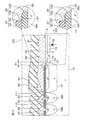
図2は、図1のII-II線に沿う断面図である。図3は、図2の領域IIIの拡大図である。
図2を参照して、半導体層2は、n−型半導体基板10を含む単層構造を有している。n−型半導体基板10は、FZ(Floating Zone)法によって形成されたシリコン製のFZ基板であってもよい。
半導体層2の第2主面4の表層部には、n+型高濃度領域11が形成されている。半導体層2においてn+型高濃度領域11外のn−型領域は、n−型ドリフト領域12として形成されている。
FIG. 2 is a sectional view taken along the line II-II in FIG. FIG. 3 is an enlarged view of a region III in FIG.
Referring to FIG. 2,
An n + -type high-
半導体層2は、n−型半導体基板10の単層構造に代えて、n+型半導体基板およびn−型エピタキシャル層を含む積層構造を有していてもよい。n+型半導体基板は、シリコン製であってもよい。n−型エピタキシャル層は、n+型半導体基板の主面からシリコンをエピタキシャル成長させることによって形成されていてもよい。
このような構造の場合、n+型半導体基板がn+型高濃度領域11に相当し、n−型エピタキシャル層がn−型ドリフト領域12に相当する。
The
In the case of such a structure, the n + type semiconductor substrate corresponds to the n + type
素子形成領域6において、半導体層2の第1主面3の表層部には、p型不純物領域13が形成されている。p型不純物領域13は、平面視において半導体層2の各辺に平行な4辺を有する四角形状に形成されていてもよい。
p型不純物領域13は、半導体層2との間でpn接合部を形成している。このpn接合部により、p型不純物領域13をアノードとし、半導体層2をカソードとするpn接合ダイオードDiが形成されている。pn接合ダイオードDiは、ファーストリカバリダイオードであってもよい。
In the
The p-
外側領域7において、半導体層2の第1主面3の表層部には、p+型終端領域14が形成されている。p+型終端領域14は、p型不純物領域13のp型不純物濃度よりも高いp型不純物濃度を有している。p+型終端領域14は、p型不純物領域13よりも高濃度かつ低抵抗な領域として形成されている。
p+型終端領域14は、平面視においてp型不純物領域13の周縁に沿って延びる帯状に形成されている。p+型終端領域14は、平面視においてp型不純物領域13を取り囲む無端状(たとえば四角環状)に形成されている。p+型終端領域14の内周縁によって取り囲まれた領域により、素子形成領域6が画定されている。
In the
The p + -
p+型終端領域14の底部は、p型不純物領域13の底部に対して半導体層2の第2主面4に近い位置に形成されている。p+型終端領域14の底部は、n+型高濃度領域11から半導体層2の第1主面3側に間隔を空けて形成されている。
p+型終端領域14は、n−型ドリフト領域12の一部の領域を挟んでn+型高濃度領域11と対向している。p+型終端領域14においてp型不純物領域13側に位置する内縁領域14aは、p型不純物領域13にオーバラップしている。
The bottom of p + -
The p + -
半導体層2の厚さ方向に関して、p型不純物領域13の厚さ(深さ)は、2.0μm以上2.5μm以下であってもよい。半導体層2の厚さ方向に関して、p+型終端領域14の厚さ(深さ)は、2.5μm以上15μm以下であってもよい。
図3を参照して、半導体層2の第1主面3の表層部において、p型不純物領域13およびp+型終端領域14の間の境界領域15には、p型濃度緩和領域16が形成されている。図3では、p型濃度緩和領域16がドット状のハッチングによって示されている。
The thickness (depth) of the p-
Referring to FIG. 3, in the surface layer portion of first
p型濃度緩和領域16は、少なくともp型不純物領域13の接続領域17内に形成されている。接続領域17は、p型不純物領域13がp+型終端領域14に接続されている領域である。
p型濃度緩和領域16は、p型不純物領域13のp型不純物濃度およびp+型終端領域14のp型不純物濃度の間の濃度差を緩和している。p型濃度緩和領域16は、p型不純物領域13の接続領域17内の領域に加えて当該接続領域17外の領域にも形成されていてもよい。
The p-type
The p-type
p型濃度緩和領域16の濃度比Y/Xは、0.225以上1.0以下であってもよい。p型濃度緩和領域16の濃度比Y/Xは、0.25以上0.5以下であることが好ましい。p型濃度緩和領域16の濃度比Y/Xは、p+型終端領域14のp型不純物濃度Xに対するp型濃度緩和領域16のp型不純物濃度Yの濃度比である。
p+型終端領域14のp型不純物濃度Xは、1.0×1017cm−3以上5.0×1017cm−3以下(たとえば2.0×1017cm−3程度)であってもよい。p型濃度緩和領域16のp型不純物濃度Yは、1×1016cm−3以上1.0×1017cm−3以下であってもよい。p型濃度緩和領域16のp型不純物濃度Yは、4.5×1016cm−3以上8.0×1016cm−3以下であることが好ましい。
The concentration ratio Y / X of the p-type
The p-type impurity concentration X of the p + -
p型濃度緩和領域16と同様の機能を有するp型不純物領域13が形成されてもよい。つまり、p+型終端領域14のp型不純物濃度Xに対するp型不純物領域13のp型不純物濃度Zの濃度比Z/Xは、p型濃度緩和領域16の濃度比Y/Xと等しい範囲(Z/X=Y/X)に設定されてもよい。
図2を再度参照して、外側領域7において、半導体層2の第1主面3の表層部には、p+型フィールドリミット領域群18が形成されている。
P-
Referring again to FIG. 2, in the
p+型フィールドリミット領域群18は、複数(この形態では4個)のp+型フィールドリミット領域18A〜18D(以下、単に「p+型フィールドリミット領域18A〜18D」という。)を含む。p+型フィールドリミット領域18A〜18Dは、p+型終端領域14からスクライブ領域8に向けてこの順に間隔を空けて形成されている。
p+型フィールドリミット領域18A〜18Dは、それぞれ、p+型終端領域14およびスクライブ領域8の間の領域において、平面視においてp+型終端領域14を取り囲むように無端状(たとえば四角環状)に形成されている。p+型フィールドリミット領域18A〜18Dは、FLR(Field Limiting Ring)とも称される。
The p + -type field
The p + -type
p+型フィールドリミット領域18Aおよびp+型終端領域14の間の距離W1は、15μm程度であってもよい。互いに隣り合うp+型フィールドリミット領域18A〜18Dの距離W2,W3,W4は、p+型終端領域14側からスクライブ領域8側に向けて順に広くなっている。距離W2は17μm程度であり、距離W3は19μm程度であり、距離W4は23μm程度であってもよい。
The distance W1 between the p + type
外側領域7において、半導体層2の第1主面3の表層部には、n+型チャネルストップ領域19が形成されている。n+型チャネルストップ領域19は、p+型フィールドリミット領域群18および半導体層2の周縁の間の領域に形成されている。
n+型チャネルストップ領域19は、半導体層2のn型不純物濃度よりも高いn型不純物濃度を有している。これにより、n+型チャネルストップ領域19は、半導体層2よりも高濃度かつ低抵抗な領域として形成されている。
In the
The n + type
n+型チャネルストップ領域19は、平面視においてp+型フィールドリミット領域群18を取り囲むように無端状(たとえば四角環状)に形成されている。n+型チャネルストップ領域19は、外側領域7およびスクライブ領域8の間の境界領域を横切り、半導体層2の側面5から露出していてもよい。n+型チャネルストップ領域19は、半導体層2の内方領域に形成されたpn接合部からの空乏層の拡がりを抑制する。
The n + type
図2および図3を参照して、半導体層2の第1主面3の上には、絶縁層21が形成されている。絶縁層21は、半導体層2側からこの順に積層された第1絶縁膜22および第2絶縁膜23を含む積層構造を有している。第1絶縁膜22は、SiO2を含んでいてもよい。第2絶縁膜23は、PSG(Phosphosilicate Glass)を含んでいてもよい。
絶縁層21は、第1開口24、複数の第2開口25、および、第3開口26を有している。第1開口24は、p型不純物領域13およびp+型終端領域14を露出させている。複数の第2開口25は、p+型フィールドリミット領域18A〜18Dをそれぞれ露出させている。第3開口26は、n+型チャネルストップ領域19を露出させている。
Referring to FIGS. 2 and 3, an insulating
The insulating
第1開口24は、平面視において半導体層2の各辺に平行な4辺を有する四角形状に形成されている。第1開口24を区画する内壁面は、p+型終端領域14の上に位置している。第1開口24の内壁面は、傾斜面からなる。第1開口24は、p型不純物領域13の全域に加えてp+型終端領域14の内周領域を露出させている。
複数の第2開口25は、それぞれ、p+型フィールドリミット領域18A〜18Dに沿って形成されている。各第2開口25は、平面視において四角環状に形成されている。
The
The plurality of
各第2開口25を区画する内壁面は、対応するp+型フィールドリミット領域18A〜18Dの上に位置している。複数の第2開口25は、それぞれ、対応するp+型フィールドリミット領域18A〜18Dの内方領域を露出させている。
第3開口26は、n+型チャネルストップ領域19に沿って形成されている。第3開口26は、平面視において四角環状に形成されている。第3開口26を区画する内壁面は、n+型チャネルストップ領域19の上に位置している。第3開口26は、n+型チャネルストップ領域19の内方領域を露出させている。
The inner wall surface that defines each
The
半導体層2の第1主面3の上には、電極層31が形成されている。電極層31は、アノード電極32、複数のフィールドプレート33、および、等電位ポテンシャル電極34を含む。アノード電極32は、表面電極の一例として形成されている。複数のフィールドプレート33は、フィールド電極の一例として形成されている。等電位ポテンシャル電極34は、等電位電極の一例として形成されている。
アノード電極32は、平面視において半導体層2の各辺に平行な4辺を有する四角形状に形成されている。アノード電極32は、p型不純物領域13およびp+型終端領域14に電気的に接続されている。
An
The
図3を参照して、アノード電極32は、接続部35および引き出し部36を含む。アノード電極32の接続部35は、第1開口24内に配置され、p型不純物領域13およびp+型終端領域14に接続されている。アノード電極32の接続部35は、p型濃度緩和領域16にも接続されている。
アノード電極32の接続部35は、p+型終端領域14の上に位置する接続端部35aを有している。アノード電極32の接続部35は、p型不純物領域13との間およびp+型終端領域14との間でオーミック接合を形成している。
Referring to FIG. 3,
The
アノード電極32の引き出し部36は、接続部35に接続されている。アノード電極32の引き出し部36は、第1開口24内からスクライブ領域8側に向けて絶縁層21の上に連続的に引き出されている。アノード電極32の引き出し部36は、第1開口24の傾斜面を介して絶縁層21の上に引き出されている。アノード電極32の引き出し部36は、平面視において複数のp + 型フィールドリミット領域18A〜18Dからp型不純物領域13側に間隔を空けて形成されている。アノード電極32の引き出し部36は、絶縁層21を挟んでp+型終端領域14と対向している。
アノード電極32の接続寸法S1は、30μm以上であってもよい。アノード電極32の接続寸法S1は、60μm以上であることが好ましい。アノード電極32の接続寸法S1は、p+型終端領域14に対するアノード電極32の接続部35の接続寸法である。アノード電極32の接続寸法S1は、p+型終端領域14の内周縁と、アノード電極32の接続端部35a(絶縁層21の第1開口24の内壁面)との間の距離でもある。
The
The connection dimension S1 of the
図2を再度参照して、複数のフィールドプレート33は、それぞれ、平面視においてp+型フィールドリミット領域18A〜18Dに沿って形成されている。各フィールドプレート33は、平面視において四角環状に形成されている。
各フィールドプレート33は、絶縁層21の上から対応する第2開口25に入り込んでいる。各フィールドプレート33は、対応する第2開口25内において、対応するp+型フィールドリミット領域18A〜18Dに接続されている。
Referring to FIG. 2 again, the plurality of
Each
最も外側に形成されたフィールドプレート33は、引き出し部37を含んでいてもよい。引き出し部37は、第2開口25内からスクライブ領域8側に向けて絶縁層21の上に連続的に引き出されている。
図2を参照して、等電位ポテンシャル電極34は、平面視においてn+型チャネルストップ領域19に沿って形成されている。等電位ポテンシャル電極34は、平面視において四角環状に形成されている。等電位ポテンシャル電極34は、EQR(EQui−potential Ring:等電位ポテンシャルリング)電極とも称される。
The
Referring to FIG. 2, equipotential
等電位ポテンシャル電極34は、絶縁層21の上から第3開口26に入り込んでいる。等電位ポテンシャル電極34は、第3開口26内においてn+型チャネルストップ領域19に接続されている。等電位ポテンシャル電極34の内周縁と、最も外側に形成されたフィールドプレート33の外周縁との絶縁距離Lは、30μm以上60μm以下であってもよい。
The
半導体層2の第1主面3の上には、表面保護膜41が形成されている。表面保護膜41は、電極層31を被覆している。表面保護膜41は、この形態では、素子形成領域6および外側領域7を覆い、スクライブ領域8を露出させている。表面保護膜41は、エポキシ樹脂やポリイミド樹脂等の有機系の絶縁材料を含んでいてもよい。表面保護膜41は、SiO2やSiN等の無機系の絶縁材料を含んでいてもよい。
On the first
表面保護膜41には、アノード電極32の一部の領域をアノードパッドとして露出させるパッド開口42が形成されている。半導体層2の第2主面4には、裏面電極としてのカソード電極43が接続されている。カソード電極43は、半導体層2の第2主面4を被覆しており、n+型高濃度領域11に接続されている。
図4は、参考例に係る半導体装置45を説明するための図である。図4は、図3に対応する領域の図でもある。図4において、図3等に示された構成と同様の構成については、同一の参照符号を付して説明を省略する。
The surface
FIG. 4 is a diagram for explaining a
図4を参照して、参考例に係る半導体装置45では、p型濃度緩和領域16が形成されていない。参考例に係る半導体装置45では、アノード電極32の接続部35がp+型終端領域14と接続されていない。
参考例に係る半導体装置45において、絶縁層21は、p型不純物領域13を被覆する被覆部46を有している。したがって、絶縁層21の第1開口24の内壁面は、p型不純物領域13の上に位置している。
Referring to FIG. 4, in a
In the
絶縁層21の被覆部46は、p+型終端領域14の上の領域からp型不純物領域13の上の領域に向けて延びている。絶縁層21の被覆部46は、p型不純物領域13およびp+型終端領域14の間の境界領域15を横切っている。
絶縁層21の被覆部46は、SiO2によって形成されていてもよい。絶縁層21の被覆部46は、絶縁層21のバーズビーク部であってもよい。バーズビーク部は、p型不純物領域13側に位置する部分の厚さが、p+型終端領域14側に位置する部分の厚さよりも小さい構造を有していてもよい。
The covering
The covering
参考例に係る半導体装置45では、絶縁層21の被覆部46の内壁面(内縁)によって、第1開口24の内壁面(内縁)が区画されている。この被覆部46の存在によって、アノード電極32の接続部35がp型不純物領域13だけに接続された構造になっている。
絶縁層21の接続寸法S2は、10μm程度である。絶縁層21の接続寸法S2とは、p型不純物領域13に対する絶縁層21の被覆部46の接続寸法である。絶縁層21の接続寸法S2は、p+型終端領域14の内周縁と、アノード電極32の接続端部35a(絶縁層21の第1開口24の内壁面)との間の距離でもある。
In the
The connection dimension S2 of the insulating
以下、参考例に係る半導体装置45およびに係る半導体装置1について、電気的特性を調べたので、その結果について説明する。
ここでは、電気的特性の一つであるリカバリー特性(逆回復特性)をシミュレーションにより求めた。リカバリー特性とは、アノード電極32およびカソード電極43の間の電圧がオンからオフに切り替わった際に、アノード電極32およびカソード電極43の間を流れる電流の特性のことである。
Hereinafter, the electrical characteristics of the
Here, a recovery characteristic (reverse recovery characteristic), which is one of the electrical characteristics, was obtained by simulation. The recovery characteristic is a characteristic of a current flowing between the
図5は、p+型終端領域14に対するアノード電極32の接続寸法と、リカバリー動作時の電流密度の関係を説明するためのグラフである。
図5において、縦軸は電流密度[A/cm2]であり、横軸は距離[μm]である。電流密度は、p型不純物領域13およびp+型終端領域14の間の境界領域15の近傍の電流密度である。
FIG. 5 is a graph for explaining the relationship between the connection dimension of the
In FIG. 5, the vertical axis represents current density [A / cm 2 ], and the horizontal axis represents distance [μm]. The current density is a current density near the
距離は、p+型終端領域14の内周縁を零としたときの、p+型終端領域14の内周縁と、アノード電極32の接続端部35a(絶縁層21の第1開口24の内壁面)との間の距離である。横軸の零点を基準とすると、左側の領域がアノード電極32の接続寸法S1(図3参照)に対応し、右側の領域が絶縁層21の接続寸法S2(図4参照)に対応する。
The distance between the inner peripheral edge of the p + -
図5には、プロットP1、プロットP2およびプロットP3が示されている。
プロットP1は、参考例に係る半導体装置45において、絶縁層21の接続寸法S2が10μmのときの電流密度を示している。プロットP2は、半導体装置1において、アノード電極32の接続寸法S1が30μmのときの電流密度を示している。プロットP3は、半導体装置1において、アノード電極32の接続寸法S1が60μmのときの電流密度を示している。
FIG. 5 shows a plot P1, a plot P2, and a plot P3.
Plot P1 shows the current density when the connection dimension S2 of the insulating
プロットP1を参照して、参考例に係る半導体装置45では、境界領域15の近傍の電流密度が、8000Acm−2程度であった。
これに対して、プロットP2を参照して、半導体装置1では、アノード電極32の接続寸法S1が30μmのとき、境界領域15の近傍の電流密度が、1600Acm−2程度であった。さらに、プロットP3を参照して、半導体装置1では、アノード電極32の接続寸法S1が60μmのとき、境界領域15の近傍の電流密度が、1300Acm−2程度であった。
Referring to plot P1, in
In contrast, referring to plot P2, in
図6は、p+型終端領域14に対するアノード電極32の接続寸法と、リカバリー動作時の逆方向電流IRの関係を説明するためのグラフである。
図6において、縦軸は電流[A]であり、横軸は時間[ns/div]である。縦軸において、正の領域が順方向電流IFの領域であり、負の領域が逆方向電流IRの領域である。
FIG. 6 is a graph for explaining the relationship between the connection size of the
In FIG. 6, the vertical axis represents current [A], and the horizontal axis represents time [ns / div]. On the vertical axis, the positive region is the region of the forward current IF, and the negative region is the region of the reverse current IR.
ここでは、アノード電極32およびカソード電極43の間に800Aの順方向電流IFを流していた状態から、リカバリー動作に移行し半導体層2が破壊に至るときの電流波形をシミュレーションにより調べた。
図6には、第1特性SP1(破線参照)および第2特性SP2(実線参照)が示されている。第1特性SP1は、参考例に係る半導体装置45において、絶縁層21の接続寸法S2が10μmのときの電流波形を示している。第2特性SP2は、半導体装置1において、アノード電極32の接続寸法S1が60μmのときの電流波形を示している。
Here, a current waveform when the forward current IF of 800 A was flowing between the
FIG. 6 shows a first characteristic SP1 (see a broken line) and a second characteristic SP2 (see a solid line). The first characteristic SP1 shows a current waveform when the connection dimension S2 of the insulating
第1特性SP1を参照して、参考例に係る半導体装置45では、逆方向電流IRのピーク値であるピーク逆方向電流IRPが、300Aであった。したがって、参考例に係る半導体装置45では、ピーク逆方向電流IRPが300A以上になると破壊に至る。
これに対して、第2特性SP2を参照して、半導体装置1では、逆方向電流IRのピーク値であるピーク逆方向電流IRPが、380Aであった。
Referring to the first characteristic SP1, in the
On the other hand, referring to the second characteristic SP2, in the
図5および図6を参照して、参考例に係る半導体装置45では、電流密度が比較的大きく、かつ、ピーク逆方向電流IRPの許容範囲が比較的に狭くなることが分かった。この問題の原因について、以下のような考察が成され得る。
すなわち、図4を再度参照して、参考例に係る半導体装置45では、アノード電極32がp型不純物領域13だけに接続された構造を有している。したがって、オンからオフに切り替わると、p+型終端領域14を流れる正孔がp型不純物領域13を介してアノード電極32に流れ込む。
Referring to FIGS. 5 and 6, it was found that in
That is, referring to FIG. 4 again, the
そのため、p+型終端領域14を流れる正孔およびp型不純物領域13を流れる正孔が合流する領域において電流密度が急激に高まる。p+型終端領域14を流れる正孔およびp型不純物領域13を流れる正孔は、ともに、アノード電極32およびカソード電極43の間を流れる逆方向電流IRを形成している。
また、参考例に係る半導体装置45では、p型不純物領域13のp型不純物濃度およびp+型終端領域14のp型不純物濃度の間に比較的大きな濃度差が存在している。p+型終端領域14を流れる正孔の密度(電流の電流密度)は、p型不純物領域13を流れる正孔の密度(電流の電流密度)よりも高い。したがって、オンからオフに切り替わるとき、p+型終端領域14を流れる正孔およびp型不純物領域13を流れる正孔が合流する境界領域15において電流密度が急激に高まる。
Therefore, the current density sharply increases in a region where the holes flowing through p + -
In the
しかも、参考例に係る半導体装置45では、半導体層2の第1主面3の上において、p+型終端領域14を流れる正孔およびp型不純物領域13を流れる正孔が合流する領域には、絶縁層21の被覆部46が形成されている。
合流後の正孔は、絶縁層21の被覆部46を迂回してアノード電極32に至る。そのため、絶縁層21の被覆部46が、p型不純物領域13およびp+型終端領域14の間の境界領域15において電流密度が急激に高まる1つの原因を形成している。
Moreover, in the
The holes after the merge reach the
参考例に係る半導体装置45では、上述のような電流密度の増加によってアノード電極32やp型不純物領域13の近傍において急激な温度上昇が引き起こされる。その結果、半導体層2が破壊に至り易くなり、ピーク逆方向電流IRPが低下したと考えられる。
これに対して、半導体装置1では、アノード電極32が、p型不純物領域13およびp+型終端領域14の間の境界領域15を横切っている。そして、アノード電極32は、p型不純物領域13に接続されていると同時に、p+型終端領域14と接続された接続部35を有している。
In the
On the other hand, in the
したがって、半導体装置1がオンからオフに切り替わるときには、p型不純物領域13からの正孔をアノード電極32に直接流し込むことができる。また、p+型終端領域14からの正孔もアノード電極32に直接流し込むことができる。これにより、p型不純物領域13およびp+型終端領域14の間の境界領域15において、電流密度の増加の抑制および温度上昇の抑制を図ることができる。
Therefore, when the
しかも、半導体装置1では、p型不純物領域13およびp+型終端領域14の間の境界領域15に、p型濃度緩和領域16が設けられている。p型濃度緩和領域16は、p型不純物領域13のp型不純物濃度およびp+型終端領域14のp型不純物濃度の間の濃度差を緩和する。これにより、p型不純物領域13およびp+型終端領域14の間の境界領域15において、電流密度の増加の更なる抑制および温度上昇の更なる抑制を図ることができる。
Moreover, in the
その結果、図5に示されるように、p型不純物領域13およびp+型終端領域14の境界領域15の電流密度を低下させることができる。よって、図6に示されるように、ピーク逆方向電流IRPの許容範囲の増加によって破壊耐量を向上できる半導体装置1を提供できる。
図7は、図3に対応する領域の図であって、本発明の第2実施形態に係る半導体装置51を説明するための図である。図7において、図3等に示された構成と同様の構成については、同一の参照符号を付して説明を省略する。
As a result, as shown in FIG. 5, the current density in
FIG. 7 is a diagram of a region corresponding to FIG. 3, and is a diagram for explaining a
図7を参照して、半導体装置51では、アノード電極32の接続部35が、p+型終端領域14と接続されていない。半導体装置51では、アノード電極32の接続部35が、p型不純物領域13の上に位置する接続端部35aを有している。
半導体装置51では、絶縁層21は、p型不純物領域13を被覆する被覆部52を有している。図7では、p型不純物領域13がドット状のハッチングによって示されている。絶縁層21の第1開口24の内壁面は、p型不純物領域13の上に形成されている。
Referring to FIG. 7, in
In the
絶縁層21の被覆部52は、p型不純物領域13およびp+型終端領域14の間の境界領域15を横切っている。絶縁層21の被覆部52は、p+型終端領域14の上の領域からp型不純物領域13の上の領域に向けて延びている。
絶縁層21の被覆部52は、第1絶縁膜22を含む。絶縁層21の被覆部52は、第1絶縁膜22の厚さおよび第2絶縁膜23の厚さの合計値よりも小さい厚さを有する薄膜部として形成されている。絶縁層21の被覆部52は、第1絶縁膜22に加えて第2絶縁膜23を含んでいてもよい。絶縁層21は、一様な厚さで形成されていてもよい。
The covering
The covering
半導体装置51では、絶縁層21の被覆部52の内壁面(内縁)によって、第1開口24の内壁面(内縁)が区画されている。p型不純物領域13に対する絶縁層21の被覆部52の接続寸法S3は、10μm程度であってもよい。
p型不純物領域13に対する絶縁層21の被覆部52の接続寸法S3は、p+型終端領域14の内周縁と、アノード電極32の接続端部35a(絶縁層21の第1開口24の内壁面)との間の距離でもある。
In the
The connection dimension S3 of the covering
p型濃度緩和領域16は、p型不純物領域13の接続領域17内に加えて、p型不純物領域13内にも形成されている。p型濃度緩和領域16は、被覆部52から露出するp型不純物領域13内にも形成されていることが好ましい。つまり、p型濃度緩和領域16は、被覆部52の内壁面(内縁)によって取り囲まれた領域内にも形成されていることが好ましい。
The p-type
このような構造により、絶縁層21の被覆部52の存在する場合でも、アノード電極32の接続部35が、p型不純物領域13およびp型濃度緩和領域16に接続された構造となる。
これにより、p+型終端領域14(p型濃度緩和領域16)を流れる電流と、p型不純物領域13を流れる電流とが合流する領域を、被覆部52の内壁面(内縁)から遠ざけることができる。したがって、被覆部52の内壁面(内縁)の近傍で電流密度が高まるのを抑制できる。
With such a structure, even when the covering
Thus, the region where the current flowing through the p + -type termination region 14 (the p-type concentration relaxing region 16) and the current flowing through the p-
この形態では、p型濃度緩和領域16と同様の機能を有するp型不純物領域13が形成されている。つまり、p+型終端領域14のp型不純物濃度Xに対するp型不純物領域13のp型不純物濃度Zの濃度比Z/Xは、p+型終端領域14のp型不純物濃度Xに対するp型濃度緩和領域16のp型不純物濃度Yの濃度比Y/Xと等しい値に設定されている(Z/X=Y/X)。
In this embodiment, p-
この場合、アノード電極32の接続部35は、その全域において、p型濃度緩和領域16に接続されていると見なすことができる。p+型終端領域14のp型不純物濃度X、p型濃度緩和領域16のp型不純物濃度Yおよびp型不純物領域13のp型不純物濃度Zは、第1実施形態において述べた通りであるので、具体的な説明は省略する。
図8は、p型濃度緩和領域16のp型不純物濃度と、電流密度との関係を説明するためのグラフである。
In this case, it can be considered that the
FIG. 8 is a graph for explaining the relationship between the p-type impurity concentration of p-type
図8において、縦軸は電流密度[cm−3]であり、横軸はp型濃度緩和領域16のp型不純物濃度[cm−3]である。縦軸は、より具体的には、p型不純物領域13およびp+型終端領域14の間の境界領域15の近傍の電流密度である。
図8を参照して、p型濃度緩和領域16のp型不純物濃度を増加させると、境界領域15の近傍の電流密度が低下した。一方、p型濃度緩和領域16のp型不純物濃度を低下させると、境界領域15の近傍の電流密度が増加した。
In FIG. 8, the vertical axis represents the current density [cm −3 ], and the horizontal axis represents the p-type impurity concentration [cm −3 ] of the p-type
Referring to FIG. 8, when the p-type impurity concentration in p-type
このことから、絶縁層21が被覆部52を有している場合であっても、p型濃度緩和領域16のp型不純物濃度を増加させることによって、境界領域15の近傍の電流密度の低下を図ることができることが分かった。
以上、半導体装置51では、p型不純物領域13およびp+型終端領域14の間の境界領域15に、p型濃度緩和領域16が設けられている。p型濃度緩和領域16は、p型不純物領域13の接続領域17内に加えて、絶縁層21の被覆部52の内壁面(内縁)によって取り囲まれた領域内にも形成されている。
Therefore, even when the insulating
As described above, in the
この形態では、p型不純物領域13そのものが、p型濃度緩和領域16として形成されている。p型濃度緩和領域16は、p型不純物領域13のp型不純物濃度およびp+型終端領域14のp型不純物濃度の間の濃度差を緩和する。これにより、p型不純物領域13およびp+型終端領域14の間の境界領域15の電流密度を低下させることができる(図8も併せて参照)。
In this embodiment, p-
その結果、p型不純物領域13およびp+型終端領域14の間の境界領域15の近傍において温度上昇の抑制を図ることができる。よって、ピーク逆方向電流IRPの許容範囲を増加させることができ、かつ、破壊耐量を向上できる半導体装置51を提供できる。
図9は、本発明の第3実施形態に係る半導体装置55を示す模式的な断面図である。図9において、第1実施形態において述べた構成と同様の構成については、同一の参照符号を付して説明を省略する。
As a result, it is possible to suppress a rise in temperature near the
FIG. 9 is a schematic sectional view showing a
半導体装置55は、pn接合ダイオードDiに代えて、IGBT(Insulated Gate Bipolar Transistor)が素子形成領域6に形成された構造を有するスイッチング素子である。
半導体装置55において、半導体層2の第2主面4の表層部には、n+型高濃度領域11に代えて、p+型コレクタ領域56が形成されている。半導体層2においてp+型コレクタ領域56外のn−型領域は、n−型ドリフト領域12として形成されている。
The
In the
素子形成領域6において、半導体層2の第1主面3の表層部には、p型不純物領域13が、IGBTのp型チャネル領域として形成されている。p型不純物領域13の表面部には、n+型エミッタ領域57およびp+型コンタクト領域58が形成されている。p+型コンタクト領域58は、n+型エミッタ領域57を貫通しており、p型不純物領域13に接続されている。
In the
素子形成領域6において、p型不純物領域13の表面部には、さらに、トレンチゲート構造59が形成されている。トレンチゲート構造59は、半導体層2の第1主面3の表層部を掘り下げて形成されたゲートトレンチ60を含み、当該ゲートトレンチ60にゲート絶縁膜61を挟んでゲート電極62が埋め込まれた構造を有している。
ゲート電極62は、ゲート絶縁膜61を挟んでp型不純物領域13と対向している。より具体的には、ゲート電極62は、ゲート絶縁膜61を挟んでn+型エミッタ領域57、p型不純物領域13およびn−型ドリフト領域12と対向している。ゲートトレンチ60の内壁面は、半導体層2の第1主面3の一部を形成している。
In the
半導体層2の第1主面3の上には、絶縁層21が形成されている。絶縁層21は、第1絶縁膜22および第2絶縁膜23を含む積層構造を有していてもよい。絶縁層21は、第1絶縁膜22からなる単層構造を有していてもよい。絶縁層21は、第1開口24、第2開口25および第3開口26に加えて、n+型エミッタ領域57およびp+型コンタクト領域58を露出させる第3開口63を有している。
On the first
半導体層2の第1主面3の上には、アノード電極32に代えて、表面電極の一例としてのエミッタ電極64が形成されている。エミッタ電極64は、絶縁層21の上から第3開口63に入り込んでいる。エミッタ電極64は、第3開口63内においてn+型エミッタ領域57およびp+型コンタクト領域58と電気的に接続されている。
半導体層2の第2主面4側には、カソード電極43に代えて、裏面電極としてのコレクタ電極65が形成されている。コレクタ電極65は、半導体層2の第2主面4を被覆しており、p+型コレクタ領域56と接続されている。
On the first
On the second
以上、半導体装置55のように、pn接合ダイオードDiに代えて、IGBTを備えた構造によっても、第1実施形態において述べた作用効果と同様の作用効果を奏することができる。むろん、半導体装置55に対して、第2実施形態に係る半導体装置51の構造を適用してもよい。
図10は、本発明の第4実施形態に係る半導体装置66を示す模式的な断面図である。図10において、第1実施形態および第3実施形態において述べた構成と同様の構成については、同一の参照符号を付して説明を省略する。
As described above, the same functions and effects as those described in the first embodiment can also be achieved by a structure including an IGBT instead of the pn junction diode Di as in the
FIG. 10 is a schematic sectional view showing a
半導体装置66は、第3実施形態に係るIGBTに代えて、MISFET(Metal Insulator Semiconductor Field Effect Transistor)が素子形成領域6に形成された構造を有するスイッチング素子である。
半導体層2の第2主面4の表層部には、p+型コレクタ領域56に代えて、n+型ドレイン領域67が形成されている。n+型エミッタ領域57がn+型ソース領域68に相当し、エミッタ電極64がソース電極69に相当し、コレクタ電極65がドレイン電極70に相当する構造となる。
The
In the surface portion of the second
以上、半導体装置66のように、IGBTに代えて、MISFETを備えた構造によっても、第1実施形態において述べた作用効果と同様の作用効果を奏することができる。むろん、半導体装置66に対して、第2実施形態に係る半導体装置51の構造を適用してもよい。
図11は、本発明の第5実施形態に係る半導体装置71を示す模式的な断面図である。図11において、第3実施形態において述べた構成と同様の構成については同一の参照符号を付して説明を省略する。
As described above, the same functions and effects as those described in the first embodiment can be obtained by the structure including the MISFET instead of the IGBT as in the
FIG. 11 is a schematic sectional view showing a
半導体装置71は、素子形成領域6において、トレンチゲート型のIGBTに代えて、プレーナゲート型のIGBTを含む。素子形成領域6において、半導体層2の第1主面3の表層部には、IGBTのp型チャネル領域としてのp型不純物領域13が間隔を空けて複数形成されている。
素子形成領域6は、p+型終端領域14(外側領域7)により取り囲まれた領域によって定義されている。p型不純物領域13の表層部には、当該p型不純物領域13の周縁から内側に間隔を空けてn+型エミッタ領域57およびp+型コンタクト領域58が形成されている。
The
The
素子形成領域6において、半導体層2の第1主面3上には、プレーナゲート構造72が形成されている。プレーナゲート構造72は、ゲート絶縁膜61を挟んでp型不純物領域13と対向するゲート電極62を含む。
ゲート電極62は、より具体的には、ゲート絶縁膜61を挟んでn+型エミッタ領域57、p型不純物領域13およびn−型ドリフト領域12と対向している。プレーナゲート構造72は、絶縁層21によって被覆されている。
In the
More specifically,
絶縁層21は、第1絶縁膜22および第2絶縁膜23を含む積層構造を有していてもよい。絶縁層21は、第1絶縁膜22からなる単層構造を有していてもよい。絶縁層21は、第1開口24、第2開口25および第3開口26に加えて、n+型エミッタ領域57およびp+型コンタクト領域58を露出させる第3開口63を有している。
半導体層2の第1主面3の上には、エミッタ電極64が形成されている。エミッタ電極64は、絶縁層21の上から第3開口63に入り込み、当該第3開口63内においてn+型エミッタ領域57およびp+型コンタクト領域58と電気的に接続されている。半導体層2の第2主面4側には、コレクタ電極65が形成されている。
The insulating
On the first
以上、半導体装置71のように、プレーナゲート型のIGBTを備えた構造によっても、第1実施形態において述べた作用効果と同様の作用効果を奏することができる。むろん、半導体装置66に対して、第2実施形態に係る半導体装置51の構造を適用してもよい。
また、第4実施形態のように、p+型コレクタ領域56に代えて、n+型ドレイン領域67を形成することによって、プレーナゲート型のMISFETを備えた半導体装置を採用してもよい。このような構造でも、第1実施形態において述べた作用効果と同様の作用効果を奏することができる。
As described above, even with the structure including the planar gate IGBT as in the
Further, as in the fourth embodiment, a semiconductor device having a planar gate type MISFET may be adopted by forming an n +
図12は、本発明の第6実施形態に係る半導体装置101の模式的な平面図である。図13は、図12のXIII-XIII線に沿う断面図である。図14は、図12の領域XIVの拡大図である。図15は、図12の領域XVの拡大図である。図16は、図12の領域XVIの拡大図である。図17は、図12の領域XVIIの拡大図である。
以下では、半導体装置1に対応する構造については、必要な場合を除き、同一の参照符号を付して説明を省略する。
FIG. 12 is a schematic plan view of a
Hereinafter, the structure corresponding to the
半導体装置101は、pn接合ダイオードDiを備えたダイオード素子である。図12を参照して、半導体装置101は、チップ状の半導体層2を含む。半導体層2は、素子形成領域6および外側領域7を含む。半導体層2は、この形態では、スクライブ領域8を含まない。半導体層2は、スクライブ領域8を含んでいてもよい。
図13および図14を参照して、素子形成領域6において、半導体層2の第1主面3の表層部には、p型不純物領域13が形成されている。p型不純物領域13は、表層部のp型不純物濃度が、底部のp型不純物濃度よりも高い濃度プロファイルを有している。図14では、p型不純物領域13において、p型不純物濃度が高い部分を「p」で表し、p型不純物濃度が低い部分を「p−」で表している。
The
Referring to FIGS. 13 and 14, in
p型不純物領域13および半導体層2との間のpn接合部により、p型不純物領域13をアノードとし、半導体層2をカソードとするpn接合ダイオードDiが形成されている。pn接合ダイオードDiは、ファーストリカバリダイオードであってもよい。
図13および図14を参照して、外側領域7において、半導体層2の第1主面3の表層部には、p+型終端領域14が形成されている。p+型終端領域14は、表層部のp型不純物濃度が、底部のp型不純物濃度よりも高い濃度プロファイルを有している。図14では、p+型終端領域14において、p型不純物濃度が高い部分を「p+」で表し、p型不純物濃度が低い部分を「p」で表している。
The pn junction between the p-
Referring to FIGS. 13 and 14, in
p+型終端領域14の深さは、5μm以上15μm以下(たとえば8μm程度)であってもよい。p+型終端領域14の幅は、50μm以上80μm以下(たとえば65μm程度)であってもよい。半導体層2の任意の側面5に直交する方向に沿う幅によって、p+型終端領域14の幅が定義されてもよい。
図13および図14を参照して、半導体層2の第1主面3の表層部において、p型不純物領域13およびp+型終端領域14の間の境界領域15には、p型濃度緩和領域16が形成されている。p型濃度緩和領域16の構造は、半導体装置1に係るp型濃度緩和領域16の構造と同様であるので、具体的な説明は省略する。
The depth of the p +
Referring to FIGS. 13 and 14, in the surface layer portion of first
図13、図15および図16を参照して、外側領域7において、半導体層2の第1主面3の表層部には、p+型フィールドリミット領域群18が形成されている。
p+型フィールドリミット領域群18は、複数(この形態では10個)のp+型フィールドリミット領域18A,18B,18C,18D,18E、18F,18G,18H,18I,18J(以下、単に「p+型フィールドリミット領域18A〜18J」という。)を含む。p+型フィールドリミット領域18A〜18Jは、p+型終端領域14に対してp型不純物領域13とは反対側の方向に向けてこの順に間隔を空けて形成されている。
Referring to FIGS. 13, 15 and 16, in
The p + -type field
p+型フィールドリミット領域18A〜18Jは、それぞれ、平面視においてp+型終端領域14を取り囲むように無端状(たとえば四角環状)に形成されている。p+型フィールドリミット領域18A〜18Jは、FLR(Field Limiting Ring)とも称される。
p+型フィールドリミット領域18A〜18Jは、それぞれ、表層部のp型不純物濃度が、底部のp型不純物濃度よりも高い濃度プロファイルを有している。図14や図16等では、p+型フィールドリミット領域18A〜18Jにおいて、p型不純物濃度が高い部分を「p+」で表し、p型不純物濃度が低い部分を「p」で表している。
Each of the p + type
Each of the p + -type
p+型フィールドリミット領域18A〜18Jの深さは、それぞれ、5μm以上15μm以下(たとえば8μm程度)であってもよい。p+型フィールドリミット領域18A〜18Jの幅は、それぞれ、10μm以上40μm以下(たとえば25μm程度)であってもよい。
フィールドリミット領域18Aおよびp+型終端領域14の間の距離W1は、14μm以上16μm以下(たとえば15μm程度)であってもよい。距離W1は、この形態では、フィールドリミット領域18Aの高濃度領域およびp+型終端領域14の高濃度領域の間の距離を基準に測定されている。
The depth of each of the p + type
Distance W1 between
互いに隣り合うp+型フィールドリミット領域18B〜18Jの間の距離W2〜W10は、p型不純物領域13とは反対側の方向に向けて順に広くなっている。距離W2〜W10は、この形態では、p+型フィールドリミット領域18B〜18Jの高濃度領域の間の距離を基準に測定されている。
距離W2は、15μm以上17μm以下(たとえば16μm程度)であってもよい。距離W3は、17μm以上19μm以下(たとえば18μm程度)であってもよい。距離W4は、18μm以上20μm以下(たとえば19μm程度)であってもよい。
The distances W2 to W10 between the p + -type
The distance W2 may be 15 μm or more and 17 μm or less (for example, about 16 μm). The distance W3 may be 17 μm or more and 19 μm or less (for example, about 18 μm). The distance W4 may be 18 μm or more and 20 μm or less (for example, about 19 μm).
距離W5は、20μm以上22μm以下(たとえば21μm程度)であってもよい。距離W6は、22μm以上24μm以下(たとえば23μm程度)であってもよい。距離W7は、25μm以上27μm以下(たとえば26μm程度)であってもよい。
距離W8は、28μm以上30μm以下(たとえば29μm程度)であってもよい。距離W9は、33μm以上35μm以下(たとえば34μm程度)であってもよい。距離W10は、39μm以上41μm以下(たとえば40μm程度)であってもよい。
The distance W5 may be not less than 20 μm and not more than 22 μm (for example, about 21 μm). The distance W6 may be not less than 22 μm and not more than 24 μm (for example, about 23 μm). The distance W7 may be not less than 25 μm and not more than 27 μm (for example, about 26 μm).
The distance W8 may be 28 μm or more and 30 μm or less (for example, about 29 μm). The distance W9 may be 33 μm or more and 35 μm or less (for example, about 34 μm). Distance W10 may be 39 μm or more and 41 μm or less (for example, about 40 μm).
図13および図17を参照して、外側領域7において、半導体層2の第1主面3の表層部には、n+型チャネルストップ領域19が形成されている。n+型チャネルストップ領域19は、表層部のn型不純物濃度が、底部のn型不純物濃度よりも高い濃度プロファイルを有している。図17では、n+型チャネルストップ領域19において、n型不純物濃度が高い部分を「n+」で表し、n型不純物濃度が低い部分を「n」で表している。
Referring to FIGS. 13 and 17, in
n+型チャネルストップ領域19は、半導体層2の側面5から露出している。n+型チャネルストップ領域19の幅は、80μm以上110μm以下(たとえば95μm程度)であってもよい。半導体層2の任意の側面5に直交する方向に沿う幅によって、n+型チャネルストップ領域19の幅が定義されてもよい。
図13〜図17を参照して、半導体層2の第1主面3の上には、絶縁層21が形成されている。
The n + type
Referring to FIGS. 13 to 17, insulating
絶縁層21は、半導体層2側からこの順に積層された第1絶縁膜22および第2絶縁膜23を含む積層構造を有している。第1絶縁膜22は、SiO2を含んでいてもよい。第2絶縁膜23は、PSG(Phosphosilicate Glass)を含んでいてもよい。
第1絶縁膜22の厚さは、0.5μm以上5μm以下(たとえば1.5μm程度)であってもよい。第2絶縁膜23の厚さは、0.5μm以上5μm以下(たとえば1.5μm程度)であってもよい。
The insulating
The thickness of the first insulating
絶縁層21は、第1開口24、複数(この形態では10個)の第2開口25、および、第3開口26を有している。第1開口24は、p型不純物領域13およびp+型終端領域14を露出させている。複数の第2開口25は、p+型フィールドリミット領域18B〜18Jをそれぞれ露出させている。第3開口26は、n+型チャネルストップ領域19を露出させている。
The insulating
図14を参照して、第1開口24は、平面視において半導体層2の各辺に平行な4辺を有する四角形状に形成されている。第1開口24を区画する内壁面は、p+型終端領域14の上に位置している。第1開口24は、p型不純物領域13の全域に加えてp+型終端領域14の内周領域を露出させている。
第1開口24は、より具体的には、第1絶縁膜22の内壁によって区画された第1開口部102、および、第2絶縁膜23の内壁によって区画され、第1開口部102に連通する第2開口部103を含む。
Referring to FIG. 14,
More specifically, the
第1開口24の第1開口部102の内壁面は、p+型終端領域14の上に位置している。第1開口24の第2開口部103の内壁面は、第1絶縁膜22の上に位置している。第1開口24の第2開口部103は、第1開口部102の平面面積よりも大きい平面面積を有している。
これにより、第1開口24内において、第1開口部102および第2開口部103の間には、第1開口部102の内壁面および第2開口部103の内壁面を接続する段部104が形成されている。
The inner wall surface of the
Thus, in the
図15および図16を参照して、複数の第2開口25は、それぞれ、p+型フィールドリミット領域18A〜18Jに沿って形成されている。各第2開口25は、平面視において四角環状に形成されている。
各第2開口25を区画する内壁面は、対応するp+型フィールドリミット領域18A〜18Jの上に位置している。各第2開口25は、対応するp+型フィールドリミット領域18A〜18Jの内方領域を露出させている。
Referring to FIGS. 15 and 16, a plurality of
The inner wall surface defining each
各第2開口25は、より具体的には、第1絶縁膜22の内壁によって区画された第1開口部105、および、第2絶縁膜23の内壁によって区画され、第1開口部105に連通する第2開口部106を含む。
各第2開口25の第1開口部105の内壁面は、対応するp+型フィールドリミット領域18A〜18Jの上に位置している。各第2開口25の第2開口部106の内壁面は、第1絶縁膜22の上に位置している。各第2開口25の第2開口部106は、第1開口部105の平面面積よりも大きい平面面積を有している。
More specifically, each
The inner wall surface of the
これにより、各第2開口25内において、第1開口部105および第2開口部106の間には、第1開口部105の内壁面および第2開口部106の内壁面を接続する段部107が形成されている。
各第2開口25の第1開口部105の開口幅は、3.0μm以上6.0μm以下(たとえば4.5μm程度)であってもよい。各第2開口25の第2開口部106の開口幅は、10.0μm以上12.0μm以下(たとえば11.0μm程度)であってもよい。
Accordingly, in each
The opening width of the
図17を参照して、第3開口26は、n+型チャネルストップ領域19に沿って形成されている。第3開口26は、平面視において四角環状に形成されている。
第3開口26を区画する内壁面は、n+型チャネルストップ領域19の上に位置している。第3開口26は、n+型チャネルストップ領域19の内方領域を露出させている。
第3開口26は、より具体的には、第1絶縁膜22の内壁によって区画された第1開口部108、および、第2絶縁膜23の内壁によって区画され、第1開口部108に連通する第2開口部109を含む。
Referring to FIG. 17,
The inner wall surface defining the
More specifically, the
第3開口26の第1開口部108の内壁面は、n+型チャネルストップ領域19の上に位置している。第3開口26の第2開口部109は、第1開口部108の平面面積よりも大きい平面面積を有している。
第3開口26の第2開口部109は、この形態では、半導体層2の側面5に連通している。第3開口26の第2開口部109の内壁面は、第1絶縁膜22の上に位置している。
The inner wall surface of the
In this embodiment, the
これにより、第1開口24内において、第1開口部108および第2開口部103の間には、第1開口部108の内壁面および第2開口部109の内壁面を接続する段部110が形成されている。
第3開口26の第1開口部108の開口幅は、3.0μm以上7.0μm以下(たとえば5.0μm程度)であってもよい。第3開口26の第2開口部109の開口幅は、60μm以上100μm以下(たとえば80μm程度)であってもよい。第2開口部109の開口幅は、この形態では、半導体層2の側面5から第2開口部109の内壁面までの距離でもある。
Thus, in the
The opening width of the
図12〜図17を参照して、半導体層2の第1主面3の上には、電極層31が形成されている。図12では、電極層31が、ハッチングによってそれぞれ示されている。
電極層31は、アルミニウム、銅、アルミニウムを含む合金、または、銅を含む合金の内の少なくとも1種を含んでいてもよい。電極層31は、アルミニウムを含む合金としてのAlSi合金(アルミニウムシリコン合金)を含んでいてもよい。電極層31の厚さは、5μm以上15μm以下(たとえば8μm程度)であってもよい。
Referring to FIGS. 12 to 17,
The
電極層31は、アノード電極32、複数(この形態では10本)のフィールドプレート33、および、等電位ポテンシャル電極34を含む。アノード電極32は、平面視において半導体層2の各辺に平行な4辺を有する四角形状に形成されている。アノード電極32は、p型不純物領域13およびp+型終端領域14に電気的に接続されている。
アノード電極32の周縁には、その上面から半導体層2側に向かった窪んだ切欠部111が形成されている。この切欠部111によって、アノード電極32は、断面視においてテーパ形状に形成されている。切欠部111の幅は、1μm以上10μm以下(たとえば5μm程度)であってもよい。
The
At the periphery of the
図14を参照して、アノード電極32は、半導体装置1と同様に、接続部35および引き出し部36を含む。アノード電極32の引き出し部36は、第1開口24内からp型不純物領域13とは反対側に向けて絶縁層21の上に連続的に引き出されている。
アノード電極32の引き出し部36は、第1開口24の第1開口部102の内壁面および第2開口部103の内壁面に沿って形成されている。アノード電極32の引き出し部36の幅は、50μm以上80μm以下(たとえば65μm程度)であってもよい。
Referring to FIG. 14,
The
図15を参照して、複数のフィールドプレート33は、それぞれ、平面視においてp+型フィールドリミット領域18A〜18Jに沿って形成されている。各フィールドプレート33は、平面視において四角環状に形成されている。
各フィールドプレート33は、絶縁層21の上から対応する第2開口25に入り込んでいる。各フィールドプレート33は、対応する第2開口25内において、対応するp+型フィールドリミット領域18A〜18Jに接続されている。
Referring to FIG. 15, a plurality of
Each
p+型フィールドリミット領域18A〜18Iに沿って形成された複数のフィールドプレート33の幅は、それぞれ、10μm以上30μm以下(たとえば20μm程度)であってもよい。
図15および図16を参照して、p+型フィールドリミット領域18Jに沿って形成されたフィールドプレート33は、引き出し部37を含み、他のフィールドプレート33よりも幅広に形成されている。引き出し部37は、第2開口25内からp型不純物領域13とは反対側の方向に向けて絶縁層21の上に連続的に引き出されている。
Each of the plurality of
Referring to FIGS. 15 and 16,
引き出し部37を含むフィールドプレート33のトータル幅は、20μm以上60μm以下(たとえば40μm程度)であってもよい。引き出し部37の幅は、10μm以上30μm以下(たとえば20μm程度)であってもよい。
各フィールドプレート33の内周縁および外周縁には、その上面から半導体層2側に向かった窪んだ切欠部112が形成されている。この切欠部112によって、各フィールドプレート33は、断面視においてテーパ形状に形成されている。切欠部112の幅は、1μm以上10μm以下(たとえば5μm程度)であってもよい。
The total width of the
At the inner peripheral edge and the outer peripheral edge of each
図17を参照して、等電位ポテンシャル電極34は、平面視においてn+型チャネルストップ領域19に沿って形成されている。等電位ポテンシャル電極34は、平面視において四角環状に形成されている。等電位ポテンシャル電極34は、EQR(EQui−potential Ring:等電位ポテンシャルリング)電極とも称される。
等電位ポテンシャル電極34は、絶縁層21の上から第3開口26に入り込んでいる。等電位ポテンシャル電極34は、第3開口26の第1開口部108の内壁面および第2開口部109の内壁面に接している。等電位ポテンシャル電極34は、第3開口26内においてn+型チャネルストップ領域19に接続されている。
Referring to FIG. 17,
The
等電位ポテンシャル電極34の外周縁は、半導体層2の側面5からp型不純物領域13側に間隔を空けて形成されている。電位ポテンシャル電極34の内周縁および外周縁には、その上面から半導体層2側に向かった窪んだ切欠部113が形成されている。この切欠部113によって、等電位ポテンシャル電極34は、断面視においてテーパ形状に形成されている。
The outer peripheral edge of the
等電位ポテンシャル電極34の幅は、60μm以上100μm以下(たとえば80μm程度)であってもよい。切欠部113の幅は、1μm以上10μm以下(たとえば5μm程度)であってもよい。等電位ポテンシャル電極34の外周縁および半導体層2の側面5の間の距離は、15μm以上40μm以下(たとえば25μm程度)であってもよい。
絶縁層21の上には、電極層31の表面に沿って表面保護膜41が形成されている。表面保護膜41は、この形態では、素子形成領域6および外側領域7を被覆している。表面保護膜41は、半導体層2の側面5に対して面一に形成された側面114を有している。半導体層2の側面5および表面保護膜41の側面114は、それぞれ、研削面によって形成されている。
The width of the
On the insulating
表面保護膜41には、アノード電極32の一部の領域をアノードパッドとして露出させるパッド開口42が形成されている。半導体層2の第2主面4には、裏面電極としてのカソード電極43が接続されている。カソード電極43は、半導体層2の第2主面4を被覆しており、n+型高濃度領域11に接続されている。
以上、半導体装置101によっても、半導体装置1について述べた効果と同様の効果を奏することができる。
The surface
As described above, the same effects as those described for the
第2〜第5実施形態から選択される1つの実施形態に係る構造が、半導体装置101に適用されてもよい。また、第2〜第5実施形態から選択される複数の実施形態に係る構造を組み合わせた構造が、半導体装置101に適用されてもよい。
本発明の実施形態について説明したが、本発明は、さらに他の形態で実施することもできる。
The structure according to one embodiment selected from the second to fifth embodiments may be applied to the
Although the embodiments of the present invention have been described, the present invention can be embodied in other forms.
前述の各実施形態において、絶縁層21は、次のような方法によって形成されてもよい。まず、たとえばCVD法によって絶縁材料が半導体層2の第1主面3の上に堆積される。これにより、絶縁層21のベースとなる絶縁層が形成される。次に、たとえばフォトリソグラフィおよびエッチングによって絶縁層の不要な部分が選択的に除去される。これにより、第1開口24、第2開口25および第3開口26を有する絶縁層21が形成される。
In each of the above embodiments, the insulating
前述の各実施形態において、第1絶縁膜22は、SiO2に代えてまたはこれに加えてSiNを含んでいてもよい。第2絶縁膜23は、PSGに代えてまたはこれに加えてSiNを含んでいてもよい。
前述の各実施形態において、絶縁層21は、第1絶縁膜22または第2絶縁膜23のいずれか一方だけを含む単層構造を有していてもよい。絶縁層21が単層構造を有している場合、絶縁層21は、半導体層2の第1主面3を選択的に酸化させることによって形成したLOCOS(Local Oxidation of Silicon)膜であってもよい。
In each of the above embodiments, the first insulating
In each of the above-described embodiments, the insulating
前述の各実施形態において、絶縁層21は、トレンチアイソレーション構造を有していてもよい。トレンチアイソレーション構造は、半導体層2の第1主面3の表層部を掘り下げて形成されたトレンチに絶縁体が埋設された構造を有していてもよい。
トレンチに埋設される絶縁体は、第1絶縁膜22および/または第2絶縁膜23であってもよい。トレンチアイソレーション構造は、トレンチの深さに応じて、STI(Shallow Trench Isolation)構造やDTI(Deep Trench Isolation)構造等と称されてもよい。
In each of the above embodiments, the insulating
The insulator buried in the trench may be the first insulating
前述の第2実施形態において、絶縁層21の被覆部52は、絶縁層21のバーズビーク部であってもよい。バーズビーク部は、p型不純物領域13側に位置する部分の厚さが、p+型終端領域14側に位置する部分の厚さよりも小さい構造を有していてもよい。絶縁層21がバーズビーク部を有する場合には、絶縁層21は単一の絶縁材料からなる単層構造を有していてもよい。
In the above-described second embodiment, the covering
前述の各実施形態において、p+型フィールドリミット領域群18が形成されていることが好ましいが、p+型フィールドリミット領域群18に代えて、単一のp+型フィールドリミット領域が形成された構造が採用されてもよい。
前述の各実施形態において、各半導体部分の導電型が反転された構成が採用されてもよい。つまり、p型の部分がn型とされ、n型の部分がp型とされてもよい。
In each of the above-described embodiments, the p + type field
In each of the above-described embodiments, a configuration in which the conductivity type of each semiconductor portion is inverted may be adopted. That is, the p-type portion may be n-type, and the n-type portion may be p-type.
その他、特許請求の範囲に記載された事項の範囲で種々の設計変更を施すことが可能である。 In addition, various design changes can be made within the scope of the matters described in the claims.
1 半導体装置
2 半導体層
13 p型不純物領域
14 p+型終端領域
15 境界領域
16 p型濃度緩和領域
17 p型不純物領域の接続領域
21 絶縁層
24 第1開口
32 アノード電極(表面電極)
35 アノード電極の接続部
35a 接続部の接続端部
36 アノード電極の引き出し部
51 半導体装置
55 半導体装置
56 p+型コレクタ領域
57 n+型エミッタ領域
61 ゲート絶縁膜
62 ゲート電極
64 エミッタ電極(表面電極)
66 半導体装置
67 n+型ドレイン領域
68 n+型ソース領域
69 ソース電極(表面電極)
71 半導体装置
101 半導体装置
S1 接続寸法
REFERENCE SIGNS
35
66 semiconductor device 67 n + type drain region 68 n + type source region 69 source electrode (surface electrode)
71 Connection dimensions of
Claims (21)
前記半導体層の表層部を形成する第1導電型のドリフト領域と、
前記ドリフト領域の表層部に形成され、4.5×10 16 cm −3 以上8.0×10 16 cm −3 以下の第2導電型不純物濃度を有する第2導電型の不純物領域と、
前記不純物領域の周縁に接続されるように前記不純物領域の周縁に沿って前記ドリフト領域の表層部に形成され、前記不純物領域の第2導電型不純物濃度よりも高い1.0×10 17 cm −3 以上5.0×10 17 cm −3 以下の第2導電型不純物濃度を有する第2導電型の終端領域と、
前記終端領域の周縁に沿うように前記終端領域から前記不純物領域の反対側に間隔を空けて前記ドリフト領域の表層部に形成され、前記不純物領域の第2導電型不純物濃度よりも高い第2導電型不純物濃度を有する第2導電型のフィールドリミット領域と、
前記不純物領域から離れる方向に、前記不純物領域および前記終端領域の接続領域から間隔を空けて前記終端領域の上に形成された壁面によって区画され、前記不純物領域、前記接続領域および前記終端領域を露出させる第1開口、ならびに、前記第1開口から間隔を空けて前記フィールドリミット領域を露出させる第2開口を有し、前記半導体層の上に形成された絶縁層と、
前記絶縁層の前記第1開口内において前記不純物領域、前記接続領域および前記終端領域に接続された接続部、ならびに、前記絶縁層を挟んで前記終端領域に対向するように前記第1開口から前記絶縁層の上に引き出され、平面視において前記フィールドリミット領域から前記不純物領域側に間隔を空けて形成された引き出し部を有する表面電極と、
前記表面電極から間隔を空けて前記絶縁層の上に形成され、前記第2開口内において前記フィールドリミット領域に接続されたフィールド電極と、を含み、
前記終端領域の第2導電型不純物濃度に対する前記不純物領域の第2導電型不純物濃度の濃度比が、0.25以上0.5以下であり、
前記第1開口から露出する前記接続領域および前記終端領域に対する前記表面電極の前記接続部の接続寸法が、30μm以上である、半導体装置。 A semiconductor layer;
A first conductivity type drift region forming a surface portion of the semiconductor layer;
A second conductivity type impurity region formed in a surface layer of the drift region and having a second conductivity type impurity concentration of 4.5 × 10 16 cm −3 or more and 8.0 × 10 16 cm −3 or less ;
1.0 × 10 17 cm − , which is formed on the surface of the drift region along the periphery of the impurity region so as to be connected to the periphery of the impurity region, and is higher than the impurity concentration of the second conductivity type of the impurity region. A second conductivity type termination region having a second conductivity type impurity concentration of 3 or more and 5.0 × 10 17 cm −3 or less ;
A second conductive layer, which is formed in the surface layer of the drift region at a distance from the terminal region to the opposite side of the impurity region along the periphery of the terminal region and is higher than a second conductive type impurity concentration of the impurity region. A second conductivity type field limit region having a type impurity concentration;
In a direction away from the impurity region, the region is partitioned by a wall surface formed on the terminal region at a distance from the connection region of the impurity region and the terminal region, and the impurity region , the connection region, and the terminal region are exposed. A first opening, and an insulating layer formed on the semiconductor layer, the second opening having a second opening for exposing the field limit region at an interval from the first opening;
The impurity region , the connection portion connected to the connection region and the termination region in the first opening of the insulation layer , and the first opening from the first opening so as to face the termination region with the insulation layer interposed therebetween. A surface electrode having a lead portion drawn out on the insulating layer and formed with an interval from the field limit region to the impurity region side in plan view,
The formed from the surface electrode on the insulating layer at an interval, seen including and a field electrode connected to the field limit area in said second opening,
A concentration ratio of the second conductivity type impurity concentration of the impurity region to the second conductivity type impurity concentration of the termination region is 0.25 or more and 0.5 or less;
The semiconductor device , wherein a connection dimension of the connection portion of the surface electrode to the connection region and the termination region exposed from the first opening is 30 μm or more .
前記表面電極の前記引き出し部は、前記第1開口の前記傾斜面を介して前記絶縁層の上に引き出されている、請求項1〜3のいずれか一項に記載の半導体装置。 The wall surface of the first opening includes an inclined surface,
4. The semiconductor device according to claim 1, wherein the lead portion of the surface electrode is led out onto the insulating layer via the inclined surface of the first opening. 5.
前記等電位電極は、前記第3開口内で前記チャネルストップ領域に接続されている、請求項7に記載の半導体装置。 The insulating layer includes a third opening exposing the channel stop region at a distance from the second opening,
The semiconductor device according to claim 7, wherein the equipotential electrode is connected to the channel stop region in the third opening.
前記ドリフト領域の一部の領域を挟んで前記不純物領域の底部と対向するように、前記半導体層に形成された第2導電型のコレクタ領域と、
ゲート絶縁膜を挟んで前記チャネル領域と対向するゲート電極と、をさらに含む、請求項1〜12のいずれか一項に記載の半導体装置。 A first conductivity type emitter region formed in a surface portion of the impurity region and defining a channel region of the IGBT with the drift region in the impurity region;
A second conductivity type collector region formed in the semiconductor layer so as to face a bottom of the impurity region with a part of the drift region interposed therebetween;
Through the gate insulating film further including: a gate electrode facing the channel region, the semiconductor device according to any one of claims 1 to 12.
前記ドリフト領域の一部の領域を挟んで前記不純物領域の底部と対向するように、前記半導体層に形成された第1導電型のドレイン領域と、
ゲート絶縁膜を挟んで前記チャネル領域と対向するゲート電極と、をさらに含む、請求項1〜12のいずれか一項に記載の半導体装置。 A first conductivity type source region formed in a surface layer of the impurity region and defining a channel region of the MISFET between the drift region and the impurity region in the impurity region;
A first conductivity type drain region formed in the semiconductor layer so as to face a bottom of the impurity region with a part of the drift region interposed therebetween;
Through the gate insulating film further including: a gate electrode facing the channel region, the semiconductor device according to any one of claims 1 to 12.
前記終端領域は、2.5μm以上15μm以下の厚さを有している、請求項1〜18のいずれか一項に記載の半導体装置。 The semiconductor device according to claim 1, wherein the terminal region has a thickness of not less than 2.5 μm and not more than 15 μm.
前記第2絶縁膜は、PSG(Phosphosilicate Glass)を含む、請求項20に記載の半導体装置。 21. The semiconductor device according to claim 20, wherein said second insulating film includes PSG (Phosphosilicate Glass).
Priority Applications (2)
| Application Number | Priority Date | Filing Date | Title |
|---|---|---|---|
| US15/808,146 US10347714B2 (en) | 2016-11-10 | 2017-11-09 | Semiconductor device |
| US16/428,369 US11145714B2 (en) | 2016-11-10 | 2019-05-31 | Semiconductor device |
Applications Claiming Priority (2)
| Application Number | Priority Date | Filing Date | Title |
|---|---|---|---|
| JP2016219800 | 2016-11-10 | ||
| JP2016219800 | 2016-11-10 |
Publications (3)
| Publication Number | Publication Date |
|---|---|
| JP2018082158A JP2018082158A (en) | 2018-05-24 |
| JP2018082158A5 JP2018082158A5 (en) | 2019-07-04 |
| JP6637012B2 true JP6637012B2 (en) | 2020-01-29 |
Family
ID=62197872
Family Applications (1)
| Application Number | Title | Priority Date | Filing Date |
|---|---|---|---|
| JP2017202112A Active JP6637012B2 (en) | 2016-11-10 | 2017-10-18 | Semiconductor device |
Country Status (2)
| Country | Link |
|---|---|
| US (1) | US11145714B2 (en) |
| JP (1) | JP6637012B2 (en) |
Families Citing this family (7)
| Publication number | Priority date | Publication date | Assignee | Title |
|---|---|---|---|---|
| WO2018207712A1 (en) * | 2017-05-08 | 2018-11-15 | ローム株式会社 | Semiconductor device |
| JP7146488B2 (en) * | 2018-06-29 | 2022-10-04 | 新電元工業株式会社 | Semiconductor device and its manufacturing method |
| JP7150539B2 (en) * | 2018-09-15 | 2022-10-11 | 株式会社東芝 | semiconductor equipment |
| US10580906B1 (en) * | 2018-10-01 | 2020-03-03 | Nxp B.V. | Semiconductor device comprising a PN junction diode |
| WO2021261222A1 (en) * | 2020-06-26 | 2021-12-30 | ローム株式会社 | Semiconductor device |
| WO2022196237A1 (en) * | 2021-03-17 | 2022-09-22 | ローム株式会社 | Semiconductor device and manufacturing method for semiconductor device |
| WO2022202088A1 (en) * | 2021-03-26 | 2022-09-29 | ローム株式会社 | Semiconductor device |
Family Cites Families (18)
| Publication number | Priority date | Publication date | Assignee | Title |
|---|---|---|---|---|
| US4742377A (en) * | 1985-02-21 | 1988-05-03 | General Instrument Corporation | Schottky barrier device with doped composite guard ring |
| JP2812093B2 (en) * | 1992-09-17 | 1998-10-15 | 株式会社日立製作所 | Semiconductor device having planar junction |
| US5747853A (en) * | 1996-08-07 | 1998-05-05 | Megamos Corporation | Semiconductor structure with controlled breakdown protection |
| JP3287269B2 (en) * | 1997-06-02 | 2002-06-04 | 富士電機株式会社 | Diode and manufacturing method thereof |
| JP3804375B2 (en) * | 1999-12-09 | 2006-08-02 | 株式会社日立製作所 | Semiconductor device and power switching drive system using the same |
| JP4684505B2 (en) | 2001-11-26 | 2011-05-18 | ルネサスエレクトロニクス株式会社 | Semiconductor device and power conversion device |
| JP5092610B2 (en) * | 2007-08-01 | 2012-12-05 | トヨタ自動車株式会社 | Semiconductor device |
| JP5606240B2 (en) * | 2010-09-22 | 2014-10-15 | 三菱電機株式会社 | Semiconductor device |
| JP2012199434A (en) * | 2011-03-22 | 2012-10-18 | Toshiba Corp | Semiconductor device |
| JP5637154B2 (en) * | 2012-02-22 | 2014-12-10 | トヨタ自動車株式会社 | Semiconductor device |
| CN104221156B (en) * | 2012-04-13 | 2017-03-01 | 三菱电机株式会社 | Diode |
| JP6061181B2 (en) * | 2012-08-20 | 2017-01-18 | ローム株式会社 | Semiconductor device |
| JP2014099444A (en) * | 2012-11-13 | 2014-05-29 | Renesas Electronics Corp | Semiconductor device |
| JP2014127573A (en) * | 2012-12-26 | 2014-07-07 | Rohm Co Ltd | Semiconductor device |
| WO2014142331A1 (en) * | 2013-03-14 | 2014-09-18 | 富士電機株式会社 | Semiconductor device |
| JP2014241367A (en) * | 2013-06-12 | 2014-12-25 | 三菱電機株式会社 | Semiconductor element, semiconductor element manufacturing method |
| WO2016114138A1 (en) * | 2015-01-14 | 2016-07-21 | 富士電機株式会社 | Semiconductor device |
| US9673315B2 (en) | 2015-03-24 | 2017-06-06 | Kabushiki Kaisha Toshiba | Semiconductor device, inverter circuit, driving device, vehicle, and elevator |
-
2017
- 2017-10-18 JP JP2017202112A patent/JP6637012B2/en active Active
-
2019
- 2019-05-31 US US16/428,369 patent/US11145714B2/en active Active
Also Published As
| Publication number | Publication date |
|---|---|
| JP2018082158A (en) | 2018-05-24 |
| US11145714B2 (en) | 2021-10-12 |
| US20190288062A1 (en) | 2019-09-19 |
Similar Documents
| Publication | Publication Date | Title |
|---|---|---|
| JP6637012B2 (en) | Semiconductor device | |
| JP4930894B2 (en) | Semiconductor device | |
| JP4892172B2 (en) | Semiconductor device and manufacturing method thereof | |
| JP6460016B2 (en) | Switching element | |
| US10347714B2 (en) | Semiconductor device | |
| TW201611275A (en) | Semiconductor device | |
| JP6228850B2 (en) | Semiconductor device | |
| JP2007250672A (en) | Semiconductor device | |
| JP2018120990A (en) | Semiconductor device | |
| JP2009188178A (en) | Semiconductor device | |
| JP2009176772A (en) | Semiconductor device | |
| JP2020136472A (en) | Semiconductor device | |
| JP2023065461A (en) | Semiconductor device | |
| JP2003174169A (en) | Semiconductor device | |
| TWI401807B (en) | Mesa type semiconductor device and manufacturing method thereof | |
| JP5365019B2 (en) | Semiconductor device | |
| JP2011243915A (en) | Semiconductor device and method of manufacturing the same | |
| JP2023014393A (en) | Semiconductor device | |
| JP2004039655A (en) | Semiconductor device | |
| US20220013666A1 (en) | Semiconductor device | |
| WO2018016283A1 (en) | Semiconductor device | |
| JP2019096732A (en) | Semiconductor device | |
| JP5751125B2 (en) | Semiconductor device | |
| JP7091714B2 (en) | Semiconductor equipment | |
| JP2007511913A (en) | IGBT cathode design with improved safe operating area capability |
Legal Events
| Date | Code | Title | Description |
|---|---|---|---|
| A521 | Request for written amendment filed |
Free format text: JAPANESE INTERMEDIATE CODE: A523 Effective date: 20190529 |
|
| A621 | Written request for application examination |
Free format text: JAPANESE INTERMEDIATE CODE: A621 Effective date: 20190529 |
|
| A871 | Explanation of circumstances concerning accelerated examination |
Free format text: JAPANESE INTERMEDIATE CODE: A871 Effective date: 20190529 |
|
| A975 | Report on accelerated examination |
Free format text: JAPANESE INTERMEDIATE CODE: A971005 Effective date: 20190912 |
|
| A977 | Report on retrieval |
Free format text: JAPANESE INTERMEDIATE CODE: A971007 Effective date: 20190913 |
|
| A131 | Notification of reasons for refusal |
Free format text: JAPANESE INTERMEDIATE CODE: A131 Effective date: 20190919 |
|
| A521 | Request for written amendment filed |
Free format text: JAPANESE INTERMEDIATE CODE: A523 Effective date: 20191113 |
|
| TRDD | Decision of grant or rejection written | ||
| A01 | Written decision to grant a patent or to grant a registration (utility model) |
Free format text: JAPANESE INTERMEDIATE CODE: A01 Effective date: 20191128 |
|
| A61 | First payment of annual fees (during grant procedure) |
Free format text: JAPANESE INTERMEDIATE CODE: A61 Effective date: 20191219 |
|
| R150 | Certificate of patent or registration of utility model |
Ref document number: 6637012 Country of ref document: JP Free format text: JAPANESE INTERMEDIATE CODE: R150 |
|
| R250 | Receipt of annual fees |
Free format text: JAPANESE INTERMEDIATE CODE: R250 |
|
| R250 | Receipt of annual fees |
Free format text: JAPANESE INTERMEDIATE CODE: R250 |