JP6636326B2 - Volume mapping using optical shape sensors - Google Patents
Volume mapping using optical shape sensors Download PDFInfo
- Publication number
- JP6636326B2 JP6636326B2 JP2015535130A JP2015535130A JP6636326B2 JP 6636326 B2 JP6636326 B2 JP 6636326B2 JP 2015535130 A JP2015535130 A JP 2015535130A JP 2015535130 A JP2015535130 A JP 2015535130A JP 6636326 B2 JP6636326 B2 JP 6636326B2
- Authority
- JP
- Japan
- Prior art keywords
- shape
- volume
- medical tube
- optical
- anatomical
- Prior art date
- Legal status (The legal status is an assumption and is not a legal conclusion. Google has not performed a legal analysis and makes no representation as to the accuracy of the status listed.)
- Expired - Fee Related
Links
- 230000003287 optical effect Effects 0.000 title claims description 111
- 238000013507 mapping Methods 0.000 title claims description 86
- 239000013307 optical fiber Substances 0.000 claims description 27
- 238000000034 method Methods 0.000 claims description 20
- 230000007704 transition Effects 0.000 claims description 16
- 239000012781 shape memory material Substances 0.000 claims description 7
- 239000000463 material Substances 0.000 claims description 6
- 238000005259 measurement Methods 0.000 claims description 6
- 230000005389 magnetism Effects 0.000 claims description 4
- 230000004044 response Effects 0.000 claims description 4
- 210000000056 organ Anatomy 0.000 description 41
- 239000000835 fiber Substances 0.000 description 11
- 238000003384 imaging method Methods 0.000 description 8
- 238000005452 bending Methods 0.000 description 4
- 210000002216 heart Anatomy 0.000 description 4
- 238000003325 tomography Methods 0.000 description 4
- 230000008569 process Effects 0.000 description 3
- 210000005245 right atrium Anatomy 0.000 description 3
- 238000005070 sampling Methods 0.000 description 3
- 210000003484 anatomy Anatomy 0.000 description 2
- 230000008901 benefit Effects 0.000 description 2
- 239000002872 contrast media Substances 0.000 description 2
- 239000011521 glass Substances 0.000 description 2
- 238000003780 insertion Methods 0.000 description 2
- 230000037431 insertion Effects 0.000 description 2
- 210000004072 lung Anatomy 0.000 description 2
- 238000002595 magnetic resonance imaging Methods 0.000 description 2
- 238000012986 modification Methods 0.000 description 2
- 230000004048 modification Effects 0.000 description 2
- 230000011218 segmentation Effects 0.000 description 2
- 238000011282 treatment Methods 0.000 description 2
- 230000001960 triggered effect Effects 0.000 description 2
- 238000002604 ultrasonography Methods 0.000 description 2
- 238000012800 visualization Methods 0.000 description 2
- 238000003491 array Methods 0.000 description 1
- 230000008859 change Effects 0.000 description 1
- 210000001072 colon Anatomy 0.000 description 1
- 230000006835 compression Effects 0.000 description 1
- 238000007906 compression Methods 0.000 description 1
- 238000002591 computed tomography Methods 0.000 description 1
- 239000013078 crystal Substances 0.000 description 1
- 238000013461 design Methods 0.000 description 1
- 238000003745 diagnosis Methods 0.000 description 1
- 239000012530 fluid Substances 0.000 description 1
- 230000006870 function Effects 0.000 description 1
- 238000003709 image segmentation Methods 0.000 description 1
- 238000002675 image-guided surgery Methods 0.000 description 1
- 230000010354 integration Effects 0.000 description 1
- 210000000936 intestine Anatomy 0.000 description 1
- 239000011159 matrix material Substances 0.000 description 1
- 239000012528 membrane Substances 0.000 description 1
- 239000002184 metal Substances 0.000 description 1
- 229910001092 metal group alloy Inorganic materials 0.000 description 1
- 238000001465 metallisation Methods 0.000 description 1
- 238000002324 minimally invasive surgery Methods 0.000 description 1
- 238000012544 monitoring process Methods 0.000 description 1
- HLXZNVUGXRDIFK-UHFFFAOYSA-N nickel titanium Chemical compound [Ti].[Ti].[Ti].[Ti].[Ti].[Ti].[Ti].[Ti].[Ti].[Ti].[Ti].[Ni].[Ni].[Ni].[Ni].[Ni].[Ni].[Ni].[Ni].[Ni].[Ni].[Ni].[Ni].[Ni].[Ni] HLXZNVUGXRDIFK-UHFFFAOYSA-N 0.000 description 1
- 229910001000 nickel titanium Inorganic materials 0.000 description 1
- RVTZCBVAJQQJTK-UHFFFAOYSA-N oxygen(2-);zirconium(4+) Chemical compound [O-2].[O-2].[Zr+4] RVTZCBVAJQQJTK-UHFFFAOYSA-N 0.000 description 1
- 229920000642 polymer Polymers 0.000 description 1
- 238000002600 positron emission tomography Methods 0.000 description 1
- 238000001959 radiotherapy Methods 0.000 description 1
- 238000004088 simulation Methods 0.000 description 1
- 210000002784 stomach Anatomy 0.000 description 1
- 230000001225 therapeutic effect Effects 0.000 description 1
- 210000003932 urinary bladder Anatomy 0.000 description 1
- 210000004291 uterus Anatomy 0.000 description 1
Images


Classifications
-
- A—HUMAN NECESSITIES
- A61—MEDICAL OR VETERINARY SCIENCE; HYGIENE
- A61B—DIAGNOSIS; SURGERY; IDENTIFICATION
- A61B5/00—Measuring for diagnostic purposes; Identification of persons
- A61B5/0059—Measuring for diagnostic purposes; Identification of persons using light, e.g. diagnosis by transillumination, diascopy, fluorescence
- A61B5/0082—Measuring for diagnostic purposes; Identification of persons using light, e.g. diagnosis by transillumination, diascopy, fluorescence adapted for particular medical purposes
- A61B5/0084—Measuring for diagnostic purposes; Identification of persons using light, e.g. diagnosis by transillumination, diascopy, fluorescence adapted for particular medical purposes for introduction into the body, e.g. by catheters
-
- A—HUMAN NECESSITIES
- A61—MEDICAL OR VETERINARY SCIENCE; HYGIENE
- A61B—DIAGNOSIS; SURGERY; IDENTIFICATION
- A61B34/00—Computer-aided surgery; Manipulators or robots specially adapted for use in surgery
- A61B34/20—Surgical navigation systems; Devices for tracking or guiding surgical instruments, e.g. for frameless stereotaxis
-
- A—HUMAN NECESSITIES
- A61—MEDICAL OR VETERINARY SCIENCE; HYGIENE
- A61B—DIAGNOSIS; SURGERY; IDENTIFICATION
- A61B5/00—Measuring for diagnostic purposes; Identification of persons
- A61B5/02—Detecting, measuring or recording pulse, heart rate, blood pressure or blood flow; Combined pulse/heart-rate/blood pressure determination; Evaluating a cardiovascular condition not otherwise provided for, e.g. using combinations of techniques provided for in this group with electrocardiography or electroauscultation; Heart catheters for measuring blood pressure
- A61B5/0205—Simultaneously evaluating both cardiovascular conditions and different types of body conditions, e.g. heart and respiratory condition
- A61B5/02055—Simultaneously evaluating both cardiovascular condition and temperature
-
- A—HUMAN NECESSITIES
- A61—MEDICAL OR VETERINARY SCIENCE; HYGIENE
- A61B—DIAGNOSIS; SURGERY; IDENTIFICATION
- A61B5/00—Measuring for diagnostic purposes; Identification of persons
- A61B5/103—Detecting, measuring or recording devices for testing the shape, pattern, colour, size or movement of the body or parts thereof, for diagnostic purposes
- A61B5/107—Measuring physical dimensions, e.g. size of the entire body or parts thereof
- A61B5/1073—Measuring volume, e.g. of limbs
-
- A—HUMAN NECESSITIES
- A61—MEDICAL OR VETERINARY SCIENCE; HYGIENE
- A61B—DIAGNOSIS; SURGERY; IDENTIFICATION
- A61B5/00—Measuring for diagnostic purposes; Identification of persons
- A61B5/103—Detecting, measuring or recording devices for testing the shape, pattern, colour, size or movement of the body or parts thereof, for diagnostic purposes
- A61B5/107—Measuring physical dimensions, e.g. size of the entire body or parts thereof
- A61B5/1076—Measuring physical dimensions, e.g. size of the entire body or parts thereof for measuring dimensions inside body cavities, e.g. using catheters
-
- A—HUMAN NECESSITIES
- A61—MEDICAL OR VETERINARY SCIENCE; HYGIENE
- A61B—DIAGNOSIS; SURGERY; IDENTIFICATION
- A61B5/00—Measuring for diagnostic purposes; Identification of persons
- A61B5/68—Arrangements of detecting, measuring or recording means, e.g. sensors, in relation to patient
- A61B5/6846—Arrangements of detecting, measuring or recording means, e.g. sensors, in relation to patient specially adapted to be brought in contact with an internal body part, i.e. invasive
- A61B5/6847—Arrangements of detecting, measuring or recording means, e.g. sensors, in relation to patient specially adapted to be brought in contact with an internal body part, i.e. invasive mounted on an invasive device
- A61B5/6852—Catheters
- A61B5/6853—Catheters with a balloon
-
- A—HUMAN NECESSITIES
- A61—MEDICAL OR VETERINARY SCIENCE; HYGIENE
- A61B—DIAGNOSIS; SURGERY; IDENTIFICATION
- A61B5/00—Measuring for diagnostic purposes; Identification of persons
- A61B5/68—Arrangements of detecting, measuring or recording means, e.g. sensors, in relation to patient
- A61B5/6846—Arrangements of detecting, measuring or recording means, e.g. sensors, in relation to patient specially adapted to be brought in contact with an internal body part, i.e. invasive
- A61B5/6847—Arrangements of detecting, measuring or recording means, e.g. sensors, in relation to patient specially adapted to be brought in contact with an internal body part, i.e. invasive mounted on an invasive device
- A61B5/6852—Catheters
- A61B5/6858—Catheters with a distal basket, e.g. expandable basket
-
- A—HUMAN NECESSITIES
- A61—MEDICAL OR VETERINARY SCIENCE; HYGIENE
- A61B—DIAGNOSIS; SURGERY; IDENTIFICATION
- A61B34/00—Computer-aided surgery; Manipulators or robots specially adapted for use in surgery
- A61B34/20—Surgical navigation systems; Devices for tracking or guiding surgical instruments, e.g. for frameless stereotaxis
- A61B2034/2046—Tracking techniques
- A61B2034/2051—Electromagnetic tracking systems
-
- A—HUMAN NECESSITIES
- A61—MEDICAL OR VETERINARY SCIENCE; HYGIENE
- A61B—DIAGNOSIS; SURGERY; IDENTIFICATION
- A61B34/00—Computer-aided surgery; Manipulators or robots specially adapted for use in surgery
- A61B34/20—Surgical navigation systems; Devices for tracking or guiding surgical instruments, e.g. for frameless stereotaxis
- A61B2034/2046—Tracking techniques
- A61B2034/2061—Tracking techniques using shape-sensors, e.g. fiber shape sensors with Bragg gratings
-
- A—HUMAN NECESSITIES
- A61—MEDICAL OR VETERINARY SCIENCE; HYGIENE
- A61B—DIAGNOSIS; SURGERY; IDENTIFICATION
- A61B90/00—Instruments, implements or accessories specially adapted for surgery or diagnosis and not covered by any of the groups A61B1/00 - A61B50/00, e.g. for luxation treatment or for protecting wound edges
- A61B90/06—Measuring instruments not otherwise provided for
- A61B2090/063—Measuring instruments not otherwise provided for for measuring volume
-
- A—HUMAN NECESSITIES
- A61—MEDICAL OR VETERINARY SCIENCE; HYGIENE
- A61B—DIAGNOSIS; SURGERY; IDENTIFICATION
- A61B2562/00—Details of sensors; Constructional details of sensor housings or probes; Accessories for sensors
- A61B2562/02—Details of sensors specially adapted for in-vivo measurements
- A61B2562/0261—Strain gauges
- A61B2562/0266—Optical strain gauges
-
- A—HUMAN NECESSITIES
- A61—MEDICAL OR VETERINARY SCIENCE; HYGIENE
- A61B—DIAGNOSIS; SURGERY; IDENTIFICATION
- A61B2562/00—Details of sensors; Constructional details of sensor housings or probes; Accessories for sensors
- A61B2562/04—Arrangements of multiple sensors of the same type
- A61B2562/043—Arrangements of multiple sensors of the same type in a linear array
-
- A—HUMAN NECESSITIES
- A61—MEDICAL OR VETERINARY SCIENCE; HYGIENE
- A61B—DIAGNOSIS; SURGERY; IDENTIFICATION
- A61B5/00—Measuring for diagnostic purposes; Identification of persons
- A61B5/68—Arrangements of detecting, measuring or recording means, e.g. sensors, in relation to patient
- A61B5/6846—Arrangements of detecting, measuring or recording means, e.g. sensors, in relation to patient specially adapted to be brought in contact with an internal body part, i.e. invasive
- A61B5/6847—Arrangements of detecting, measuring or recording means, e.g. sensors, in relation to patient specially adapted to be brought in contact with an internal body part, i.e. invasive mounted on an invasive device
- A61B5/6852—Catheters
- A61B5/6857—Catheters with a distal pigtail shape
-
- A—HUMAN NECESSITIES
- A61—MEDICAL OR VETERINARY SCIENCE; HYGIENE
- A61B—DIAGNOSIS; SURGERY; IDENTIFICATION
- A61B90/00—Instruments, implements or accessories specially adapted for surgery or diagnosis and not covered by any of the groups A61B1/00 - A61B50/00, e.g. for luxation treatment or for protecting wound edges
- A61B90/06—Measuring instruments not otherwise provided for
Landscapes
- Health & Medical Sciences (AREA)
- Life Sciences & Earth Sciences (AREA)
- Surgery (AREA)
- Engineering & Computer Science (AREA)
- General Health & Medical Sciences (AREA)
- Public Health (AREA)
- Veterinary Medicine (AREA)
- Animal Behavior & Ethology (AREA)
- Biomedical Technology (AREA)
- Heart & Thoracic Surgery (AREA)
- Medical Informatics (AREA)
- Molecular Biology (AREA)
- Physics & Mathematics (AREA)
- Biophysics (AREA)
- Pathology (AREA)
- Dentistry (AREA)
- Oral & Maxillofacial Surgery (AREA)
- Cardiology (AREA)
- Physiology (AREA)
- Robotics (AREA)
- Nuclear Medicine, Radiotherapy & Molecular Imaging (AREA)
- Pulmonology (AREA)
- Endoscopes (AREA)
- Measurement Of The Respiration, Hearing Ability, Form, And Blood Characteristics Of Living Organisms (AREA)
- Length Measuring Devices By Optical Means (AREA)
- Instruments For Viewing The Inside Of Hollow Bodies (AREA)
- Measuring And Recording Apparatus For Diagnosis (AREA)
- Image Processing (AREA)
Description
本発明は、広くは、解剖学的体積の境界の一部又は全体の三次元(3D)形状を感知するように部分的に又は完全に境界を持つ解剖学的体積内の1以上の医学的ツール(例えば、バルーン、バスケット、形状記憶チューブ等)により固定される光学的形状センサに関する。本発明は、特には、前記光学的形状センサの形状感知能力、及び妥当な場合には前記医学的ツールの物理的幾何構成に基づいて前記境界を持つ解剖学的体積の一部又は全体の3D形状をマッピングすることに関する。 The present invention generally relates to one or more medical devices within an anatomical volume that is partially or completely bounded to sense a three-dimensional (3D) shape of part or all of the anatomical volume boundary. An optical shape sensor secured by a tool (eg, balloon, basket, shape memory tube, etc.). The present invention particularly relates to the 3D of part or all of the anatomical volume with the boundaries based on the shape sensing capabilities of the optical shape sensor and, where appropriate, the physical geometry of the medical tool. Related to mapping shapes.
当技術分野において知られているように、撮像システムは、患者の目標器官(例えば、潜在的に癌性の器官又は異常機能器官)の画像を生成する既知の撮像モダリティ(例えば、X線、コンピュータ断層撮影、磁気共鳴撮像、超音波、陽電子放出断層撮影、及び単光子放出断層撮影)を実施するのに使用されうる。これらの画像は、患者の診断に対して及び/又は前記器官の様々な治療(例えば、画像ガイド手術、放射線治療等)を計画及び実行するのに医師により使用されうる。前記目標器官に対する正確な治療計画を容易化するために、前記目標器官は、前記画像内の前記目標器官の輪郭の識別及び視覚化に対してセグメント化される必要がありうる。 As is known in the art, imaging systems include known imaging modalities (eg, x-ray, computer, etc.) that generate images of a target organ (eg, a potentially cancerous or abnormally functioning organ) of a patient. Tomography, magnetic resonance imaging, ultrasound, positron emission tomography, and single photon emission tomography). These images may be used by a physician for diagnosis of a patient and / or for planning and performing various treatments of the organ (eg, image guided surgery, radiation therapy, etc.). To facilitate an accurate treatment plan for the target organ, the target organ may need to be segmented for identification and visualization of the contour of the target organ in the image.
しかしながら、前記画像は、金属が生体構造を不明瞭にする又は干渉する場合に、前記画像内の前記目標器官の輪郭の識別及び視覚化が不可能である又はエラーが発生しやすいかもしれないので、読み取るのが難しいかもしれない。画像セグメンテーションは、典型的には、前記目標器官の輪郭を電子的に描くように前記目標器官の表面上の様々な店を選択するように高度な訓練を受けた医師に要求する。これは、時間がかかり、エラーを受けやすい可能性がある。より具体的には、器官と内部流体との間の境界の設定は、前記器官の貧弱な視覚化のため難しいかもしれない。造影剤は、特定の生体構造を強調するのを助けるのに使用されうるが、一部の人々は、造影剤に敏感である。 However, the image may be incapable of identifying or visualizing the contours of the target organ in the image if the metal obscures or interferes with anatomy or may be error prone. , May be difficult to read. Image segmentation typically requires a highly trained physician to select various stores on the surface of the target organ to electronically outline the target organ. This can be time consuming and error prone. More specifically, setting a boundary between an organ and an internal fluid may be difficult due to poor visualization of said organ. Contrast agents can be used to help highlight certain anatomy, but some people are sensitive to contrast agents.
代わりに、例えば、米国特許出願公開2008/0008369A1により開示される境界再パラメータ化(reparameterization)方法のような、自動セグメンテーションプログラムが、使用されてもよい。しかしながら、前述の刊行物により認識されるように、前記目標器官の境界は、覆いかぶさるフィーチャによる陰影及び異なるグレイレベルの2つの領域により又は2つの異なるテクスチャの間の縁として、又はこれら2つのハイブリッドとして、形成される誤った縁のため、前記画像において弱く現れる、スペックルノイズの存在によりマスクされることを含む様々な理由で識別するのが難しいかもしれない。この複雑さは、画像ベースの自動セグメンテーションアルゴリズムに対して高い失敗率を引き起こす。 Alternatively, an automatic segmentation program may be used, such as, for example, the boundary reparameterization method disclosed by US Patent Application Publication 2008 / 0008369A1. However, as will be recognized by the aforementioned publications, the boundaries of the target organ may be shaded by overlying features and by two regions of different gray levels or as an edge between two different textures, or by a hybrid of the two. As a result, false edges that are formed may be difficult to identify for a variety of reasons, including being masked by the presence of speckle noise, which appears weak in the image. This complexity causes a high failure rate for image-based automatic segmentation algorithms.
本発明の目的は、解剖学的体積(例えば、中空器官)の形状を測定し、オプションとして、動き、歪、磁性、電圧、気体流、流量、温度、圧力、生化学的状態及び固有の組織特性又は外部要因に対する組織の応答に関する他の特徴を含むが、これらに限定されない様々なパラメータを測定するマッピング方法を提供することである。特に、形状/パラメータ測定は、経時的に生じてもよく、これにより前記解剖学的体積の四次元(4D)情報を生成してもよい。 It is an object of the present invention to measure the shape of an anatomical volume (eg, a hollow organ), and optionally to determine movement, strain, magnetism, voltage, gas flow, flow, temperature, pressure, biochemical conditions and native tissue It is to provide a mapping method that measures various parameters, including but not limited to characteristics or other characteristics of the tissue's response to external factors. In particular, shape / parameter measurements may occur over time, thereby generating four-dimensional (4D) information of the anatomical volume.
このために、本発明は、前記体積の境界の一部又は全体の三次元(3D)形状をマッピングするように医学的ツールにより部分的に又は完全に境界を持つ解剖学的体積内で規則的に配置され、固定される光学的形状センサを提供する。 To this end, the present invention provides a method for mapping regular or partially bounded anatomical volumes by medical tools to map a three-dimensional (3D) shape of some or all of the boundaries of the volume. To provide an optical shape sensor that is positioned and secured to the optical sensor.
本発明の一形式は、解剖学的体積の境界の一部又は全体をマッピングするように解剖学的体積内で配置可能な体積マッピング器具である。前記体積マッピング器具は、1以上の医学的ツールを使用し、各医学的ツールは、前記医学的ツールを前記解剖学的体積内に規則的に配置するための配置可能な構造形態と、前記解剖学的体積の境界に対して各医学的ツールを固定するためのマッピング構造形態との間で遷移する。 One form of the present invention is a volume mapping instrument that can be positioned within an anatomical volume to map a portion or the entire anatomical volume boundary. The volume mapping instrument uses one or more medical tools, each medical tool comprising a deployable structural form for regularly positioning the medical tool within the anatomical volume; Transition to and from a mapping configuration for securing each medical tool to the boundaries of the geometric volume.
前記医学的ツールの例は、(1)収縮した圧縮状態と膨張した拡張状態との間で遷移する医学的バルーン、(2)細長い形状と球状形状との間で医学的バスケットを遷移させる形状記憶材料を含む前記医学的バスケット、及び(3)細長い形状とらせん形状との間で医学的チューブを遷移させる形状記憶材料を含む前記医学的チューブを含むが、これらに限定されない。 Examples of such medical tools include (1) a medical balloon transitioning between a contracted compressed state and an expanded expanded state, (2) a shape memory transitioning a medical basket between an elongated shape and a spherical shape. Including, but not limited to, the medical basket containing material, and (3) the medical tube containing a shape memory material that transitions the medical tube between an elongated shape and a helical shape.
前記体積マッピング器具は、前記医学的ツールに隣接した光学的形状センサを使用し、前記光学的形状センサは、各医学的ツールが前記解剖学的体積内で前記配置可能な構造形態から前記マッピング構造形態に遷移されるのに応じて前記解剖学的体積の境界の一部又は全体の形状を示す1以上の符号化された光学的信号を生成するように構造的に構成される。 The volume mapping instrument uses an optical shape sensor adjacent to the medical tool, wherein the optical shape sensor determines the mapping structure from the positionable configuration of each medical tool within the anatomical volume. Structurally configured to generate one or more encoded optical signals indicative of the shape of some or all of the boundaries of the anatomical volume as transitioned to a configuration.
本発明の第2の形式は、前述の体積マッピング器具を使用し、前記符号化された光学的信号に基づいて前記解剖学的体積の境界の一部又は全体をマッピングするように体積マッピングモジュールを使用する体積マッピングシステムである。 A second form of the invention uses a volume mapping instrument as described above and configures a volume mapping module to map part or all of the anatomical volume boundary based on the encoded optical signal. The volume mapping system used.
本発明の第3の形式は、前述の体積マッピングシステムを使用する体積マッピング方法である。前記体積マッピング方法は、前記解剖学的体積内に各医学的ツールを規則的に配置すること、及び前記解剖学的体積の境界に対して前記解剖学的体積内に配置されるように各医学的ツールを固定することを含む。前記体積マッピング方法は、各医学的ツールが前記解剖学的体積の境界に対して固定されるのに応じて、前記解剖学的体積の境界の一部又は全体の形状を示す1以上の符号化された光学的信号を生成する前記光学的形状センサの動作、及び前記符号化された光学的信号に基づく前記解剖学的体積の境界の一部又は全体のマッピングを含む。 A third type of the present invention is a volume mapping method using the volume mapping system described above. The volume mapping method includes regularly placing each medical tool within the anatomical volume, and placing each medical tool within the anatomical volume relative to a boundary of the anatomical volume. Includes fixing mechanical tools. The volume mapping method may include one or more encodings that indicate the shape of some or all of the anatomical volume boundary as each medical tool is fixed relative to the anatomical volume boundary. Operation of the optical shape sensor to generate an encoded optical signal, and mapping of some or all of the boundaries of the anatomical volume based on the encoded optical signal.
本発明の前述の形式及び他の形式並びに本発明の様々なフィーチャ及び利点は、添付の図面と併せて読まれる本発明の様々な実施例の以下の詳細な記載から明らかになる。詳細な記載及び図面は、本発明を限定するのではなく、単に説明し、本発明の範囲は、添付の請求項及びその同等物により規定される。 The foregoing and other forms of the invention, as well as various features and advantages of the invention, will be apparent from the following detailed description of various embodiments of the invention, read in conjunction with the accompanying drawings. The detailed description and drawings are merely illustrative of the invention rather than limiting, the scope of the invention being defined by the appended claims and equivalents thereof.
図1は、1以上の光学的形状センサ及び1以上の医学的ツールを使用する本発明の体積マッピング器具を示す。一般に、部分的に又は完全に囲まれた解剖学的体積をマッピングする目的に対して、各光学的形状センサ30は、前記解剖学的体積の境界の一部又は全体の三次元(3D)形状をマッピングし、オプションとして、動き、歪、磁性、電圧、気体流、流量、温度、圧力、生化学的状態及び固有の組織特性又は外部要因に対する組織の応答に関する他の特徴を含むが、これらに限定されない様々なパラメータを測定するように、医学的ツール40により前記境界を持つ解剖学的体積内に規則的に配置され、固定される。前記解剖学的体積の例は、心臓、肺、膀胱、胃、腸、子宮及び結腸からなる図1に示されるような患者10の中空器官11を含むが、これらに限定されない。
FIG. 1 illustrates a volume mapping instrument of the present invention using one or more optical shape sensors and one or more medical tools. Generally, for the purpose of mapping a partially or completely enclosed anatomical volume, each
特に、本発明の目的に対して、光学的形状センサ30は、変形光学的センサアレイ31を介する連続した内部光反射を用いて光を送るように構造的に構成されたいかなる物品としてここに広く規定され、アレイ31の各変形光学的センサは、特定の波長の光を反射し、他の全ての波長の光を透過し、これにより反射波長が光学的形状センサ30に加えられる外部刺激の関数としてシフトされうるように構造的に構成されるいかなる物品としてここに広く規定される。光学的形状センサ30の例は、当技術分野において既知であるようなファイバの長さに沿って一体化されたファイバ・ブラッグ・グレーティングのアレイを組み込む可撓性光透過ガラス又はプラスチックファイバ、及び当技術分野において既知であるようなファイバの長さに沿って発生する光学的屈折率のランダム変化(例えば、レイリー散乱)を自然に持つ可撓性光透過ガラス又はプラスチックファイバを含むが、これらに限定されない。
In particular, for the purposes of the present invention,
明確性のため、3つのセンサ31のみが各光ファイバ30に対して示されているが、実際には、光ファイバ30は、当業者により理解されるように光ファイバ30の長さに対して小さいバージョンのセンサ31を多数、使用する。
For clarity, only three
実際に、各光学的形状センサ30は、光学的形状センサ30の3D曲げ感知を容易化するいかなる構成の1以上の変形光学的センサアレイを使用してもよい。
In fact, each
例えば、単一の光ファイバ実施例において、光学的形状センサ30は、光学的形状センサ30による3D曲げ感知に対して要求されるように120°間隔で配置された3つのファイバ・ブラッグ・グレーティングを持つ、又は光学的形状センサ30による3D曲げ感知に対して要求されるように60°間隔で配置された6つのファイバ・ブラッグ・グレーティングを持つ単一の光ファイバである。いずれの場合にも、追加のファイバ・ブラッグ・グレーティングが、構成内の中央ファイバ・ブラッグ・グレーティング・アレイとして使用されてもよい。
For example, in a single optical fiber embodiment, the
また、例により、複数光ファイバ実施例において、光学的形状センサ30は、各光ファイバが単一のファイバ・ブラッグ・グレーティングを持つ3つの光ファイバを含み、前記光ファイバが、光学的形状センサ30による3D曲げ感知に対して要求されるように120°間隔で配置され、又は各光ファイバが単一のファイバ・ブラッグ・グレーティングを持つ6つの光ファイバを含み、前記光ファイバが、光学的形状センサ30による3D曲げ感知に対して要求されるように60°間隔で配置される。いずれの場合にも、追加の光ファイバが、構成内の中央光ファイバとして使用されてもよい。
Also, by way of example, in a multiple optical fiber embodiment,
動作において、各光学的形状センサ30は、光学的形状センサ30の瞬間的な形状サンプリングにおいて光学的形状センサ30の形状を示す前記連続した内部光反射に基づいて各変形光学的センサアレイに対する符号化された光学的信号を発生する。より具体的には、瞬間的な形状サンプリングに対して又は複数の形状サンプリングにわたって、前記符号化された光学的信号は、光学的形状センサ30が、医学的ツール40により前記境界を持つ体積内で規則的に配置及び固定されるので、光学的形状センサ30の形状を示す。前記符号化された光学的信号は、したがって、後でより詳細にここで説明されるように及び前記マッピングされた体積を視覚的に表示する(例えば、図1に示されるマッピングされた体積52の表示53)ために前記体積(例えば、図1に示される心臓12のマッピングされた体積52)の境界をマッピングするために各光学的形状センサ30の使用を容易化する。
In operation, each
パラメータ測定に対して、変形光学的センサアレイ31は、参照にここに組み込まれるWO2011/048509により教示されるようにこのような測定を提供する材料からなる及び/又はコーティングされてもよい。このような材料の例は、電圧感知に対するBi12TiO20結晶、磁気感知に対するNi−Mn−Ga記憶形状金属合金、及び強化された温度感知に対するZn金属蒸着を含むが、これらに限定されない。
For parameter measurements, the modified
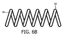
本発明の目的に対して、医学的ツール40は、解剖学的体積内に医学的ツール40を規則的に配置するための配置可能な構造形態と前記解剖学的体積の境界に対して医学的ツール40を固定するためのマッピング構造形態との間で遷移するように構造的に構成されたいかなる物品としてここに広く規定される。医学的ツール40の例は、収縮した圧縮状態と膨張した拡張状態との間で遷移する医学的バルーン41、変形された細長い形状と自然な球状形状との間で医学的バスケットを遷移させる形状記憶材料を含む医学的バスケット42、変形された細長い形状と自然ならせん形状との間で医学的チューブを遷移させる形状記憶材料を含む医学的チューブ43を含むが、これらに限定されない。
For the purposes of the present invention, the
各光学的形状センサ30は、前記解剖学的体積の境界の一部又は全体の3D形状をマッピングするために医学的ツール40による前記境界を持つ解剖学的体積内の規則的配置及び固定を容易化するような形で医学的ツール40に隣接する。本発明の目的に対して、用語「隣接」は、外部刺激が遷移中に光学的形状センサ30に加えられるように、医学的ツール40の前記配置可能な構造形態と前記マッピング構造形態との間の遷移が光学的形状センサ30により感知されるように、医学的ツール40に対して光学的形状センサ30を物理的に相互作用するいかなる手段としても広く規定される。
Each
例えば、図2に示される医学的バルーンの実施例において、光学的形状センサ30は、らせんパターンで医学的バルーン41を越え、これにより、医学的バルーン41の圧縮又は拡張が、光学的形状センサ30に加えられる外部刺激を変化させるので、収縮した状態(図2A)と膨張した状態(図2B)との間の医学的バルーン41の遷移が、光学的形状センサ30により感知される。実際に、設計されたらせんパターンにおける光学的形状センサ30は、体積マッピングに対する最大膨張状態における医学的バルーン41に隣接してもよく、これにより、前記らせんパターンは、医学的バルーン41が前記最大膨張状態からある程度収縮されるときはいつでも、それに応じて医学的バルーン41とともに圧縮する。前記らせんパターンの例は、図3に示されるアルキメデスのらせんパターン及び図4に示されるフェルマのらせんパターンを含むが、これらに限定されない。
For example, in the medical balloon embodiment shown in FIG. 2, the
図8に関連して後にここで説明されるように、体積マッピング器具20が、デリバリ器具64(図1)により前記解剖学的体積内に進められ、前記解剖学的体積内で前記膨張状態に遷移されるので、各医学的バルーン41は、収縮した状態で動作される。このように、光学的形状センサ30は、医学的バルーン41が前記解剖学的体積内で膨張されるような時間まで各医学的バルーン41の収縮した感知を提供する。
As will be described later in connection with FIG. 8, the
また、例により、図5に示される医学的バスケットの実施例において、医学的バスケット42は、形状記憶材料(例えば、ニチノールワイヤ)を含み、これにより、医学的バスケット42は、変形された細長い形状(図5A)と自然な球状形状(図5B)との間で遷移し、医学的バスケットの変形又は緩和が、光学的形状センサ30に加えられる外部刺激を変化させるので、前記細長い形状と前記球状形状との間のいかなる遷移も、光学的形状センサ30により感知される。実際に、光学的形状センサ30は、前記体積マッピングに対する前記自然な球状形状において医学的バスケット42に隣接してもよく、これにより、光学的形状センサ30は、医学的バスケット42が前記自然な球状形状からある程度、変形されるときはいつでも、局所的に伸長する。
Also by way of example, in the embodiment of the medical basket shown in FIG. 5, the
図8に関連して後でここに説明されるように、体積マッピング器具20が、デリバリ器具64(図1)により前記解剖学的体積内に進められ、前記解剖学的体積内で前記自然な球状形状に遷移されるので、各医学的バスケット42は、変形された細長い形状で動作される。このように、光学的形状センサ30は、医学的バスケット42が、前記解剖学的体積内で自然な球状形状を再開するような時間まで、各医学的バスケット42の細長い感知を提供する。
As will be described later in connection with FIG. 8, a
他の例により、図5に示される医学的チューブの実施例において、医学的チューブ43は、形状記憶材料(例えば、ニチノール管)を含み、これにより、医学的チューブ43は、変形された細長い形状(図6A)と自然ならせん形状(図6B)との間で遷移し、医学的チューブの変形又は緩和が、光学的形状センサ30に加えられる外部刺激を変化させるので、前記細長い形状と前記らせん形状との間のいかなる遷移も、光学的形状センサ30により感知される。実際に、光学的形状センサ30は、前記体積マッピングに対する前記自然ならせん形状において医学的チューブ43に隣接してもよく、これにより、光学的形状センサ30は、医学的チューブ43が前記自然ならせん形状からある程度変形されるときはいつでも、局所的に伸長する。
According to another example, in the embodiment of the medical tube shown in FIG. 5, the
図9と関連して後にここで説明されるように、体積マッピング器具20は、デリバリ器具64(図1)により前記解剖学的体積内に進めされ、前記解剖学的体積内で前記自然ならせん形状に遷移されるので、医学的チューブ43は、変形された細長い形状において動作される。このように、光学的形状センサ30は、医学的チューブ43が前記解剖学的体積内で自然ならせん形状を再開するような時間まで医学的チューブ43の細長い感知を提供する。
As will be described later in connection with FIG. 9, the
体積マッピング器具20の更なる理解を容易化するために、図7に示されるフローチャート80により表される本発明の体積マッピング方法が、ここに記載される。フローチャート80の記載は、図1に示される患者10の中空の肺11の体積マッピングに関連して提供される。
To facilitate a further understanding of the
図1及び7を参照すると、フローチャート80の段S81は、患者10の中空器官11の撮像と、中空器官11に体積マッピング器具20を進める経路の計画とを含む。中空器官11を撮像するために、撮像システム60が、撮像座標系61内の中空器官11の画像を生成する既知の撮像モダリティ(例えば、X線、コンピュータ断層撮影、磁気共鳴撮像、超音波、陽電子放出断層撮影、単光子放出断層撮影)を実施するのに使用される。
Referring to FIGS. 1 and 7, step S81 of
中空器官11に体積マッピング器具20を進める経路を計画するために、経路プランナ62及び/又は手術ナビゲータ63が、中空器官11に体積マッピング器具20を進める手段として使用されるべきデリバリ器具64のタイプに依存して既知の計画技術を実施するように使用される。
To plan a path for advancing the
例えば、カテーテル又は内視鏡であるデリバリ器具64に関連して、計画プランナ62は、2007年4月17日に公開され、"3D Tool Path Planning, Simulation and Control System"と題されたTrovato他に対する国際出願WO2007/022986A2により教示される技術を実施してもよく、これは、患者10の生成された画像内の前記カテーテル又は内視鏡に対する運動学的に正しい経路を生成するのに使用されうる。
For example, in connection with a
代わりに、カテーテル又は内視鏡であるデリバリ器具64に関連して、手術ナビゲータ62は、患者10の生成された画像内の前記カテーテル又は内視鏡を追跡する電磁又は光学的ガイダンスシステムを使用してもよい。このような手術ナビゲータの一例は、カテーテル又は内視鏡に対するグローバル・ポジショニング・システム(GPS)のように動作するPhilips Medicalにより商業的に提供されるPercuNavシステムである。
Alternatively, in connection with a
また、例により、入れ子式カニューレであるデリバリ器具64に関連して、経路プランナ62は、2008年3月20日に公開され、"Active Cannula Configuration For Minimally Invasive Surgery"と題されたTrovato他に対する国際出願WO2008/032230A1により教示される技術を実施してもよく、これは、患者10の生成された画像内の前記入れ子式カニューレに対する運動学的に正しい構成を生成するのに使用されうる。
Also, by way of example, in connection with a
フローチャート80の段S82は、中空器官11内の体積マッピング器具20の規則的な配置及び固定を含む。実際に、中空器官11に体積マッピング器具20を送る手順は、医学的ツール40及びデリバリ器具64のタイプに依存する。2つの例が、ここに記載される。
Step S82 of
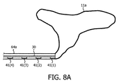
図8に示されるように中空器官11の全体的な境界を含む第1の例に対して、医学的ツール40は、4つの医学的バルーン41を含み、デリバリ器具64は、カテーテル64aである。医学的バルーン41は、単一の光学的形状センサ30の遠位端に沿って空間的に分配され、カテーテル64a内で圧縮された収縮状態である。1以上の光ファイバを持つ光学的形状センサ30の一実施例において、各光ファイバの光学的形状センサ30は、らせんパターンで(チャネルを開いたまま保つためのワイヤ又は高分子コイルチューブのような壁要素を持つ又は持たない)各医学的バルーン41の表面内のチャネルを通過してもよく、これは、医学的バルーン41が拡張することを可能にしながら、可撓性であるが、比較的伸縮不可能な光ファイバによる形状追跡を可能にする。前記パターン内の各光ファイバの末端は、可撓性膜内の全ての方向において機械的に拘束される固定点を構成してもよく、前記光ファイバに沿った他の点は、前記光ファイバが埋め込まれる可撓性マトリクス内のチャネル/溝に平行なスライドする境界条件で自由にスライドすることを可能にされる。
For the first example, which includes the general boundaries of the
更に、各光ファイバの緩い長さは、医学的バルーン41に向けて続くので、医学的バルーン41の各端部に取り付けられてもよい。前記長さは、好ましくは、最短経路長と各医学的バルーン41の拡張された表面上の距離との間である。各医学的バルーン41は、中空器官11他の医学的バルーン41によりある程度圧縮されるので、前記経路は、拡張された医学的バルーン41のサイズを示すべきである。
In addition, the loose length of each optical fiber continues toward the
光学的形状センサ30が、図8Bを単純化するように各医学的バルーン41を長手方向に横切るように図8Bに示されることに注意されたい。それにもかかわらず、実際には、図3及び4に示される球状パターンに配置される光学的形状センサ30は、医学的バルーン41の膨張の光学的感知を提供する。
Note that
カテーテル64aは、図8Aに示されるように中空器官11aの特定の侵入点に前記体積マッピング器具を送るようにナビゲートされてよく、これにより、前記体積マッピング器具は、中空器官11a内の前記体積マッピング器具、特に医学的バルーン41の規則的な配置を容易化するように設計されたパターンで中空器官11a内に進められる。代わりに、カテーテル64aは、中空器官11内の前記体積マッピング器具、特に医学的バルーン41の規則的な配置を容易化するように設計されたパターンで中空器官11内に進められてもよい。
The
いずれの場合にも、一度医学的バルーン41が中空器官11a内に規則的に配置されると、医学的バルーン41は、中空器官11aの境界に対して医学的バルーン41を固定するように膨張される。実際に、医学的バルーン41は、自動的にトリガされてもよく、これにより、膨張は、作動基準(例えば、器具挿入の深度)を評価するように医学的バルーン41内の埋め込まれたセンサからの測定値(例えば、温度、歪、幾何構成、湿度、pO2、pCO2等)を入力として取り込む空気圧式アクチュエータにより自動的に開始される。代わりに、医学的バルーン41の膨張は、中空器官11aの境界に対する最適な固定プロファイルを達成するようにプログラム可能な又は自動化されたシーケンスで時間調整されてもよい。トリガ又はタイマを用いて、医学的バルーン41は、各医学的バルーン41が中空器官11aに入るにつれて順次的に、又は代わりに2以上の医学的バルーン41の挿入後に膨張されてもよい。
In any case, once the
また、実際に、撮像システム60は、中空器官11a内で医学的バルーン41を規則的に配置する及び/又は中空器官11aの境界に対する医学的バルーン41の許容可能な固定を視覚化するのに使用されてもよい。
Also, in practice, the
当業者は、図8の例に対する医学的バルーン41の代わりに医学的バスケット42(図1)の代替的な使用を理解する。
One skilled in the art will appreciate the alternative use of a medical basket 42 (FIG. 1) instead of the
図9に示されるような心臓12を含む第2の例に対して、医学的ツール40は、らせん状チューブ43であり、デリバリ器具は、カニューレ64bである。図6に示されるように、細長い形状を持つ光学的形状センサ30は、カニューレ64bを通って細長い形状に延びるらせん状チューブ43を通って延びる。この例において、カニューレ64bは、心臓12の右心房12a内に進められるように長手方向に拡張され、前記体積マッピング器具は、コイル44により右心房43に固定される。カニューレ64bは、この後に、図9に示されるように右心房12aの開口まで後退され、らせん状チューブ43及び光学的形状センサ30は、らせん状チューブ43の通常のらせん形状を仮定し、右心房12aの境界に対して固定すると推定する。
For the second example, including the
図7を再び参照すると、フローチャート80の段S83は、前記生成された画像内の中空器官11の体積マッピングを含む。実際に、光学的形状センサ30が、画像座標系62(図1)内の長さに沿った光学的形状センサの3Dの位置を検出しうるという事実の観点から、中空器官11内の光学的形状センサ30の分布、医学的ツール40による光学的形状センサ30の固定点の設計、及び固定の度合いは、医学的ツール40が中空器官11に対して固定されるので中空器官11の正確なマッピングに対して考慮すべき重要なマッピング要因である。
Referring again to FIG. 7, step S83 of
図1を参照すると、形状センサコントローラ50及び体積マッピングモジュール51は、光学的形状センサ30の符号化された光学的信号を処理し、これにより光学的形状センサ30の一部又は全体的な形状を再構成するのに使用される。本発明の目的に対して、形状センサコントローラ50は、光学的形状センサ30を通して光を伝送し、変形光学的センサアレイによる伝送光の連続した内部反射により生成される前記符号化された光学的信号を受け取るように構造的に構成されたいかなる装置又はシステムとしてもここに広く規定される。形状センサコントローラ50の一例は、光学的形状センサ30を通して光を伝送し、変形光学的センサアレイによる前記伝送光の前記連続した内部反射により生成される前記符号化された光学的信号を受け取る、当技術分野において既知である、光結合器、広帯域基準反射器及び周波数領域反射率計を含むが、これらに限定されない。
Referring to FIG. 1, a
本発明の目的に対して、体積マッピングモジュール52は、光学的形状センサ30の形状を部分的に又は全体的に再構成するように前記符号化された光学的信号を処理するように構造的に構成されたいかなる物品としても広く規定される形状再構成器を含む。前記形状再構成器の一例は、既知の形状再構成技術を実施するようにいかなるタイプのコンピュータ(例えば、図1に示されるワークステーション53)上にソフトウェア及び/又はファームウェアとしてインストールされる再構成エンジンを含むが、これに限定されない。特に、光学的形状センサ30の形状に一体化される歪/曲げ測定に前記符号化された光学的信号を関連付ける既知の形状再構成技術である。
For the purposes of the present invention,
体積マッピングモジュール52は、光学的形状センサ21の再構成された形状及び適用可能である場合に前記マッピング構造形態における医学的ツール40の物理的幾何構成を処理し、画像座標系61内の中空器官11の境界の3D形状を提供するように構造的に構成されたいかなる物品又は装置としても広く規定漁れる画像マッパを含む。
The
例えば、図8Bに関連して、ドット90−97は、医学的ツール40の固定による中空器官11のエッジを表し、したがって中空器官12に対する光学的形状センサ30の様々な感知点を表す。前述のマッピング要因の観点から、体積マッピングは、直線及び/又は弧(例えば、ベジエ曲線)としてのドット90−97間の接続により達成されうる。当業者により理解されるように、ドット90−97の増加は、前記画像マッパによる前記解剖学的体積のより正確な体積マッピングをもたらす。
For example, with reference to FIG. 8B, dots 90-97 represent the edges of
段S83の完了後に、前記体積マッピングは、様々な診断及び/又は治療目的に対して使用されうる。例えば、形状マッピングされた境界は、マルチモダリティデータ位置合わせ/統合に対して固定された解剖学的体積/フィーチャを規定するのに使用されてもよく、これにより、形状追跡器具空間及び撮像/監視空間は、重畳され、所望の目標に向けた形状追跡装置の強化されたガイダンスを可能にする。 After completion of step S83, the volume mapping can be used for various diagnostic and / or therapeutic purposes. For example, shape-mapped boundaries may be used to define a fixed anatomical volume / feature for multi-modality data registration / integration, thereby providing shape tracking instrument space and imaging / monitoring. The space is superimposed, allowing enhanced guidance of the shape tracker towards a desired target.
当業者は、本発明の体積マッピング器具の原理をいかなるタイプの医学的処置に応用する方法も理解するだろう。 One skilled in the art will understand how to apply the principles of the volume mapping device of the present invention to any type of medical procedure.
当業者は、本発明の体積マッピング器具の利益を更に理解するだろう。 One skilled in the art will further appreciate the benefits of the volume mapping device of the present invention.
本発明の様々な実施例が、図示及び記載されているが、ここに記載された本発明の実施例が、説明に役立つものであり、本発明の真の範囲から逸脱することなしに、様々な変更及び修正が行われてもよく、同等物が要素に対して代用されてもよいと、当業者により理解されるだろう。加えて、多くの修正は、中心的な範囲から逸脱することなしに本発明の教示を適応させるように行われてもよい。したがって、本発明が、本発明を実行すると期待されるベストモードとして開示される特定の実施例に限定されないが、本発明が、添付の請求項の範囲に入る全ての実施例を含むことが意図される。 While various embodiments of the invention have been illustrated and described, it will be appreciated that the embodiments of the invention described herein are illustrative and that the invention can be practiced without departing from the true scope of the invention. It will be understood by those skilled in the art that various changes and modifications may be made and equivalents may be substituted for the elements. In addition, many modifications may be made to adapt the teachings of the present invention without departing from the central scope. Therefore, it is not intended that the invention be limited to the specific embodiments disclosed as the best mode expected to practice the invention, but that the invention should include all embodiments falling within the scope of the appended claims. Is done.
Claims (9)
少なくとも1つの医学的チューブであって、各医学的チューブが、形状記憶材料を含み、前記解剖学的体積内に前記医学的チューブを規則的に配置するための細長い形状と前記解剖学的体積の境界に対して前記医学的チューブを固定するためのらせん形状との間で遷移する、前記医学的チューブと、
各医学的チューブに隣接した光学的形状センサであって、各医学的チューブが前記解剖学的体積内で前記細長い形状から前記らせん形状に遷移するのに応じて前記解剖学的体積の前記境界の少なくとも一部の形状を示す少なくとも1つの符号化された光学的信号を生成するように構造的に構成される、当該光学的形状センサと、
を有する、体積マッピング器具。 A volume mapping instrument positionable within an enclosed anatomical volume for mapping at least a portion of an anatomical volume boundary,
At least one medical tube, wherein each medical tube includes a shape memory material, and has an elongated shape for regularly placing the medical tube within the anatomical volume; Transitioning between a helical shape to secure the medical tube relative to a boundary, the medical tube;
An optical shape sensor adjacent to each medical tube, wherein the medical tube transitions from the elongate shape to the helical shape within the anatomical volume to define the boundary of the anatomical volume. An optical shape sensor structurally configured to generate at least one encoded optical signal indicative of at least a portion of the shape;
A volume mapping instrument having:
解剖学的体積内で配置可能な体積マッピング器具であって、
少なくとも1つの医学的チューブであって、各医学的チューブが、形状記憶材料を含み、前記解剖学的体積内に前記医学的チューブを規則的に配置するための細長い形状と前記解剖学的体積の境界に対して前記医学的チューブを固定するためのらせん形状との間で遷移する、前記医学的チューブ、及び
各医学的チューブに隣接した光学的形状センサであって、各医学的チューブが前記解剖学的体積内で前記細長い形状から前記らせん形状に遷移するのに応じて前記解剖学的体積の前記境界の少なくとも一部の形状を示す少なくとも1つの符号化された光学的信号を生成するように構造的に構成される、当該光学的形状センサ、
を有する、当該体積マッピング器具と、
前記少なくとも1つの符号化された光学的信号を受け取るのに応じて前記解剖学的体積の前記境界の少なくとも一部をマッピングする体積マッピングモジュールと、
を有する、体積マッピングシステム。 In a volume mapping system that maps at least a portion of a boundary of an enclosed anatomical volume,
A volume mapping device that can be positioned within an anatomical volume,
At least one medical tube, wherein each medical tube includes a shape memory material, and has an elongated shape for regularly placing the medical tube within the anatomical volume; Wherein the medical tube transitions between a spiral shape for securing the medical tube relative to a boundary, and an optical shape sensor adjacent to each medical tube, wherein each medical tube is associated with the anatomical shape. Generating at least one encoded optical signal indicative of a shape of at least a portion of the boundary of the anatomical volume in response to transitioning from the elongated shape to the spiral shape within a anatomical volume. The optical shape sensor structurally configured,
Having the volume mapping device;
A volume mapping module that maps at least a portion of the boundary of the anatomical volume in response to receiving the at least one encoded optical signal;
A volume mapping system comprising:
各医学的チューブが、前記解剖学的体積内で前記医学的チューブを規則的に配置するための細長い形状から前記解剖学的体積の前記境界に対して前記医学的チューブを固定するためのらせん形状に遷移するステップであって、前記光学的形状センサが前記各医学的チューブの固定を感知する、ステップと、
各医学的チューブが前記解剖学的体積の前記境界に対して固定されるのに応じて、前記光学的形状センサが前記解剖学的体積の前記境界の少なくとも一部の形状を示す少なくとも1つの符号化された光学的信号を生成するステップと、
前記少なくとも1つの符号化された光学的信号に基づいて前記解剖学的体積の前記境界の少なくとも一部をマッピングするステップと、
を有する、方法。 A volume mapping device that includes at least one medical tube that includes a shape memory material and maps an optical shape sensor adjacent to the at least one medical tube to map at least a portion of an enclosed anatomical volume boundary. In the method of operating a volume mapping system to be arranged,
Each medical tube has an elongated shape for regularly positioning the medical tube within the anatomical volume, to a helical shape for securing the medical tube to the boundary of the anatomical volume. Wherein the optical shape sensor senses the fixation of each of the medical tubes,
At least one sign indicating the shape of at least a portion of the boundary of the anatomical volume as the medical tube is secured relative to the boundary of the anatomical volume. Generating a structured optical signal;
Mapping at least a portion of the boundary of the anatomical volume based on the at least one encoded optical signal;
A method comprising:
Applications Claiming Priority (3)
| Application Number | Priority Date | Filing Date | Title |
|---|---|---|---|
| US201261708768P | 2012-10-02 | 2012-10-02 | |
| US61/708,768 | 2012-10-02 | ||
| PCT/IB2013/058687 WO2014053941A1 (en) | 2012-10-02 | 2013-09-20 | Volume mapping using optical shape sensors |
Related Child Applications (1)
| Application Number | Title | Priority Date | Filing Date |
|---|---|---|---|
| JP2019191046A Division JP2020089717A (en) | 2012-10-02 | 2019-10-18 | Volume mapping using optical shape sensor |
Publications (3)
| Publication Number | Publication Date |
|---|---|
| JP2016500525A JP2016500525A (en) | 2016-01-14 |
| JP2016500525A5 JP2016500525A5 (en) | 2016-10-27 |
| JP6636326B2 true JP6636326B2 (en) | 2020-01-29 |
Family
ID=49709778
Family Applications (2)
| Application Number | Title | Priority Date | Filing Date |
|---|---|---|---|
| JP2015535130A Expired - Fee Related JP6636326B2 (en) | 2012-10-02 | 2013-09-20 | Volume mapping using optical shape sensors |
| JP2019191046A Pending JP2020089717A (en) | 2012-10-02 | 2019-10-18 | Volume mapping using optical shape sensor |
Family Applications After (1)
| Application Number | Title | Priority Date | Filing Date |
|---|---|---|---|
| JP2019191046A Pending JP2020089717A (en) | 2012-10-02 | 2019-10-18 | Volume mapping using optical shape sensor |
Country Status (7)
| Country | Link |
|---|---|
| US (1) | US10653320B2 (en) |
| EP (1) | EP2903517A1 (en) |
| JP (2) | JP6636326B2 (en) |
| CN (2) | CN104684471A (en) |
| BR (1) | BR112015007129A2 (en) |
| RU (1) | RU2666580C2 (en) |
| WO (1) | WO2014053941A1 (en) |
Families Citing this family (10)
| Publication number | Priority date | Publication date | Assignee | Title |
|---|---|---|---|---|
| CN104684471A (en) * | 2012-10-02 | 2015-06-03 | 皇家飞利浦有限公司 | Volume mapping using optical shape sensors |
| CN117323001A (en) | 2014-09-08 | 2024-01-02 | 皇家飞利浦有限公司 | Optical fiber shape sensing system |
| EP3037056B1 (en) | 2014-12-23 | 2021-04-21 | Stryker European Holdings I, LLC | System for reconstructing a trajectory of an optical fiber |
| US11478304B2 (en) * | 2015-03-31 | 2022-10-25 | Medtronic Navigation, Inc. | Flexible circuit coils |
| JP6739454B2 (en) * | 2015-06-24 | 2020-08-12 | コーニンクレッカ フィリップス エヌ ヴェKoninklijke Philips N.V. | System and method for tracking and characterizing inflatable medical devices using FORS data |
| CN107847197A (en) * | 2015-08-05 | 2018-03-27 | 波士顿科学医学有限公司 | Intelligent apparatus for bladder mapping |
| US10905329B2 (en) * | 2016-06-09 | 2021-02-02 | Biosense Webster (Israel) Ltd. | Multi-function conducting elements for a catheter |
| EP3484572B1 (en) | 2016-07-15 | 2022-04-06 | Koninklijke Philips N.V. | Flexible instrument comprising shape sensing optical fibers, method and computer program product |
| US10132891B2 (en) * | 2016-09-16 | 2018-11-20 | General Electric Company | System and method for attenuation correction of a surface coil in a PET-MRI system |
| US10918310B2 (en) * | 2018-01-03 | 2021-02-16 | Biosense Webster (Israel) Ltd. | Fast anatomical mapping (FAM) using volume filling |
Family Cites Families (25)
| Publication number | Priority date | Publication date | Assignee | Title |
|---|---|---|---|---|
| US5465717A (en) * | 1991-02-15 | 1995-11-14 | Cardiac Pathways Corporation | Apparatus and Method for ventricular mapping and ablation |
| US5255678A (en) | 1991-06-21 | 1993-10-26 | Ecole Polytechnique | Mapping electrode balloon |
| US5263493A (en) * | 1992-02-24 | 1993-11-23 | Boaz Avitall | Deflectable loop electrode array mapping and ablation catheter for cardiac chambers |
| US5752518A (en) * | 1996-10-28 | 1998-05-19 | Ep Technologies, Inc. | Systems and methods for visualizing interior regions of the body |
| US6192266B1 (en) * | 1998-03-26 | 2001-02-20 | Boston Scientific Corporation | Systems and methods for controlling the use of diagnostic or therapeutic instruments in interior body regions using real and idealized images |
| US6741878B2 (en) * | 2001-12-14 | 2004-05-25 | Biosense Webster, Inc. | Basket catheter with improved expansion mechanism |
| US6736822B2 (en) * | 2002-02-20 | 2004-05-18 | Mcclellan Scott B. | Device and method for internal ligation of tubular structures |
| JP2004251779A (en) | 2003-02-20 | 2004-09-09 | Fuji Photo Optical Co Ltd | Three-dimensional shape detector for long flexible member |
| US7004911B1 (en) * | 2003-02-24 | 2006-02-28 | Hosheng Tu | Optical thermal mapping for detecting vulnerable plaque |
| CN101247998B (en) | 2005-08-26 | 2012-11-28 | 欧瑞康纺织有限及两合公司 | Textile machine |
| CN101282693B (en) | 2005-10-11 | 2011-07-06 | 皇家飞利浦电子股份有限公司 | 3d tool path planning, simulation and control system |
| US7599588B2 (en) * | 2005-11-22 | 2009-10-06 | Vascular Imaging Corporation | Optical imaging probe connector |
| EP2036037B1 (en) | 2006-05-18 | 2013-04-17 | Resonant Medical Inc. | Methods and systems for segmentation using boundary reparameterization |
| RU2445934C2 (en) | 2006-09-14 | 2012-03-27 | Конинклейке Филипс Электроникс Н.В. | Active cannula configuration for minimally invasive surgery |
| US7720322B2 (en) * | 2008-06-30 | 2010-05-18 | Intuitive Surgical, Inc. | Fiber optic shape sensor |
| US20100030063A1 (en) * | 2008-07-31 | 2010-02-04 | Medtronic, Inc. | System and method for tracking an instrument |
| US9545216B2 (en) * | 2011-08-05 | 2017-01-17 | Mc10, Inc. | Catheter balloon methods and apparatus employing sensing elements |
| KR101764438B1 (en) | 2009-03-26 | 2017-08-02 | 인튜어티브 서지컬 오퍼레이션즈 인코포레이티드 | System for providing visual guidance for steering a tip of an endoscopic device towards one or more landmarks and assisting an operator in endoscopic navigation |
| JP5952736B2 (en) * | 2009-10-23 | 2016-07-13 | コーニンクレッカ フィリップス エヌ ヴェKoninklijke Philips N.V. | Light-sensitive interventional instrument for rapid dispersion measurement of biophysical parameters |
| WO2011138691A1 (en) * | 2010-05-07 | 2011-11-10 | Koninklijke Philips Electronics N.V. | Motion compensation and patient feedback in medical imaging systems |
| JP6362246B2 (en) * | 2010-08-23 | 2018-07-25 | コーニンクレッカ フィリップス エヌ ヴェKoninklijke Philips N.V. | Mapping system and method for medical procedures |
| JP2012090690A (en) | 2010-10-25 | 2012-05-17 | Fujifilm Corp | Diagnosis support apparatus |
| US8873900B2 (en) * | 2011-04-21 | 2014-10-28 | Medtronic Vascular, Inc. | Balloon catheter with integrated optical sensor for determining balloon diameter |
| EP2742321A1 (en) | 2011-09-02 | 2014-06-18 | Koninklijke Philips N.V. | Rapid dense point cloud imaging using probabilistic voxel maps |
| CN104684471A (en) * | 2012-10-02 | 2015-06-03 | 皇家飞利浦有限公司 | Volume mapping using optical shape sensors |
-
2013
- 2013-09-20 CN CN201380051791.4A patent/CN104684471A/en active Pending
- 2013-09-20 BR BR112015007129A patent/BR112015007129A2/en not_active Application Discontinuation
- 2013-09-20 JP JP2015535130A patent/JP6636326B2/en not_active Expired - Fee Related
- 2013-09-20 WO PCT/IB2013/058687 patent/WO2014053941A1/en active Application Filing
- 2013-09-20 CN CN201810366632.8A patent/CN108403088A/en active Pending
- 2013-09-20 RU RU2015116649A patent/RU2666580C2/en active
- 2013-09-20 EP EP13799382.0A patent/EP2903517A1/en not_active Withdrawn
- 2013-09-20 US US14/430,688 patent/US10653320B2/en not_active Expired - Fee Related
-
2019
- 2019-10-18 JP JP2019191046A patent/JP2020089717A/en active Pending
Also Published As
| Publication number | Publication date |
|---|---|
| JP2020089717A (en) | 2020-06-11 |
| CN108403088A (en) | 2018-08-17 |
| CN104684471A (en) | 2015-06-03 |
| JP2016500525A (en) | 2016-01-14 |
| WO2014053941A1 (en) | 2014-04-10 |
| US10653320B2 (en) | 2020-05-19 |
| BR112015007129A2 (en) | 2017-07-04 |
| EP2903517A1 (en) | 2015-08-12 |
| RU2666580C2 (en) | 2018-09-11 |
| US20150238275A1 (en) | 2015-08-27 |
| RU2015116649A (en) | 2016-11-27 |
Similar Documents
| Publication | Publication Date | Title |
|---|---|---|
| JP6636326B2 (en) | Volume mapping using optical shape sensors | |
| EP2608720B1 (en) | Mapping system for medical procedures | |
| EP3226772B1 (en) | Automatic tracking and registration of ultrasound probe using optical shape sensing without tip fixation | |
| EP2903552B1 (en) | Three dimensional polyline registration using shape constraints | |
| JP5906305B2 (en) | Artificial valve guided delivery | |
| CN105934215B (en) | The robot of imaging device with optic shape sensing controls | |
| JP7301148B2 (en) | Method for Correcting Electrode Position in Elongated Medical Devices | |
| JP6114748B2 (en) | Curved multiplanar reconstruction using optical fiber shape data | |
| CN105792768B (en) | It is tracked using the equipment longitudinally encoded | |
| US9282915B2 (en) | Method and system for generating and/or repairing a surface model of a geometric structure | |
| JP2018537143A (en) | Hub for device placement with optical shape detection guidewire | |
| JP2013534433A (en) | Optical fiber shape reconstruction | |
| EP3484572B1 (en) | Flexible instrument comprising shape sensing optical fibers, method and computer program product | |
| CN105338919B (en) | Utilize the optic shape sensing of a plurality of optical fiber | |
| US20140243687A1 (en) | Shape sensing devices for real-time mechanical function assessment of an internal organ | |
| JP5684404B2 (en) | Identification of heart geometry in response to Doppler imaging of blood flow characteristics | |
| RU2536662C2 (en) | Planning with curvature interaction, some radiuses of curvature and adaptive neighbourhood included | |
| KR20130120311A (en) | Navigation system for surgery | |
| CN113543697B (en) | Method and system for correcting electrode position of an elongate medical device | |
| JP2023528681A (en) | Guidance of balloon therapy within the anatomical cavity | |
| JP2022534916A (en) | Passive Ultrasonic Sensor-Based Initialization for Image-Based Device Segmentation |
Legal Events
| Date | Code | Title | Description |
|---|---|---|---|
| A521 | Request for written amendment filed |
Free format text: JAPANESE INTERMEDIATE CODE: A523 Effective date: 20160907 |
|
| A621 | Written request for application examination |
Free format text: JAPANESE INTERMEDIATE CODE: A621 Effective date: 20160907 |
|
| RD04 | Notification of resignation of power of attorney |
Free format text: JAPANESE INTERMEDIATE CODE: A7424 Effective date: 20170214 |
|
| A977 | Report on retrieval |
Free format text: JAPANESE INTERMEDIATE CODE: A971007 Effective date: 20170621 |
|
| A131 | Notification of reasons for refusal |
Free format text: JAPANESE INTERMEDIATE CODE: A131 Effective date: 20170704 |
|
| A521 | Request for written amendment filed |
Free format text: JAPANESE INTERMEDIATE CODE: A523 Effective date: 20170929 |
|
| A02 | Decision of refusal |
Free format text: JAPANESE INTERMEDIATE CODE: A02 Effective date: 20180227 |
|
| A521 | Request for written amendment filed |
Free format text: JAPANESE INTERMEDIATE CODE: A523 Effective date: 20180619 |
|
| A911 | Transfer to examiner for re-examination before appeal (zenchi) |
Free format text: JAPANESE INTERMEDIATE CODE: A911 Effective date: 20180627 |
|
| A131 | Notification of reasons for refusal |
Free format text: JAPANESE INTERMEDIATE CODE: A131 Effective date: 20180821 |
|
| A601 | Written request for extension of time |
Free format text: JAPANESE INTERMEDIATE CODE: A601 Effective date: 20181115 |
|
| A521 | Request for written amendment filed |
Free format text: JAPANESE INTERMEDIATE CODE: A523 Effective date: 20190206 |
|
| A131 | Notification of reasons for refusal |
Free format text: JAPANESE INTERMEDIATE CODE: A131 Effective date: 20190423 |
|
| A601 | Written request for extension of time |
Free format text: JAPANESE INTERMEDIATE CODE: A601 Effective date: 20190719 |
|
| A521 | Request for written amendment filed |
Free format text: JAPANESE INTERMEDIATE CODE: A523 Effective date: 20191018 |
|
| TRDD | Decision of grant or rejection written | ||
| A01 | Written decision to grant a patent or to grant a registration (utility model) |
Free format text: JAPANESE INTERMEDIATE CODE: A01 Effective date: 20191205 |
|
| A61 | First payment of annual fees (during grant procedure) |
Free format text: JAPANESE INTERMEDIATE CODE: A61 Effective date: 20191218 |
|
| R150 | Certificate of patent or registration of utility model |
Ref document number: 6636326 Country of ref document: JP Free format text: JAPANESE INTERMEDIATE CODE: R150 |
|
| LAPS | Cancellation because of no payment of annual fees |