JP6636161B2 - Heavy truck tires - Google Patents
Heavy truck tires Download PDFInfo
- Publication number
- JP6636161B2 JP6636161B2 JP2018533100A JP2018533100A JP6636161B2 JP 6636161 B2 JP6636161 B2 JP 6636161B2 JP 2018533100 A JP2018533100 A JP 2018533100A JP 2018533100 A JP2018533100 A JP 2018533100A JP 6636161 B2 JP6636161 B2 JP 6636161B2
- Authority
- JP
- Japan
- Prior art keywords
- layer
- rubber compound
- shoulder
- central
- tread
- Prior art date
- Legal status (The legal status is an assumption and is not a legal conclusion. Google has not performed a legal analysis and makes no representation as to the accuracy of the status listed.)
- Active
Links
- 229920001971 elastomer Polymers 0.000 claims description 81
- 239000005060 rubber Substances 0.000 claims description 79
- 150000001875 compounds Chemical class 0.000 claims description 78
- 238000005096 rolling process Methods 0.000 claims description 17
- 239000000203 mixture Substances 0.000 claims description 13
- 239000006229 carbon black Substances 0.000 claims description 7
- LZZYPRNAOMGNLH-UHFFFAOYSA-M Cetrimonium bromide Chemical compound [Br-].CCCCCCCCCCCCCCCC[N+](C)(C)C LZZYPRNAOMGNLH-UHFFFAOYSA-M 0.000 claims description 5
- 239000000945 filler Substances 0.000 description 11
- VYPSYNLAJGMNEJ-UHFFFAOYSA-N Silicium dioxide Chemical compound O=[Si]=O VYPSYNLAJGMNEJ-UHFFFAOYSA-N 0.000 description 10
- 239000011324 bead Substances 0.000 description 6
- 235000019241 carbon black Nutrition 0.000 description 6
- 239000012763 reinforcing filler Substances 0.000 description 5
- 244000043261 Hevea brasiliensis Species 0.000 description 4
- 229910020175 SiOH Inorganic materials 0.000 description 4
- PNEYBMLMFCGWSK-UHFFFAOYSA-N aluminium oxide Inorganic materials [O-2].[O-2].[O-2].[Al+3].[Al+3] PNEYBMLMFCGWSK-UHFFFAOYSA-N 0.000 description 4
- 229920003052 natural elastomer Polymers 0.000 description 4
- 229920001194 natural rubber Polymers 0.000 description 4
- 239000000377 silicon dioxide Substances 0.000 description 4
- 229920003051 synthetic elastomer Polymers 0.000 description 4
- 238000012360 testing method Methods 0.000 description 4
- OKTJSMMVPCPJKN-UHFFFAOYSA-N Carbon Chemical compound [C] OKTJSMMVPCPJKN-UHFFFAOYSA-N 0.000 description 3
- 238000005299 abrasion Methods 0.000 description 3
- 239000007822 coupling agent Substances 0.000 description 3
- 229920003244 diene elastomer Polymers 0.000 description 3
- 125000000524 functional group Chemical group 0.000 description 3
- 239000000463 material Substances 0.000 description 3
- 239000003351 stiffener Substances 0.000 description 3
- MYRTYDVEIRVNKP-UHFFFAOYSA-N 1,2-Divinylbenzene Chemical compound C=CC1=CC=CC=C1C=C MYRTYDVEIRVNKP-UHFFFAOYSA-N 0.000 description 2
- 229910000323 aluminium silicate Inorganic materials 0.000 description 2
- 230000015572 biosynthetic process Effects 0.000 description 2
- 239000003795 chemical substances by application Substances 0.000 description 2
- 239000011248 coating agent Substances 0.000 description 2
- 238000000576 coating method Methods 0.000 description 2
- 238000013461 design Methods 0.000 description 2
- HNPSIPDUKPIQMN-UHFFFAOYSA-N dioxosilane;oxo(oxoalumanyloxy)alumane Chemical compound O=[Si]=O.O=[Al]O[Al]=O HNPSIPDUKPIQMN-UHFFFAOYSA-N 0.000 description 2
- 239000000806 elastomer Substances 0.000 description 2
- 238000004519 manufacturing process Methods 0.000 description 2
- 230000002787 reinforcement Effects 0.000 description 2
- 230000003014 reinforcing effect Effects 0.000 description 2
- 229920003048 styrene butadiene rubber Polymers 0.000 description 2
- 238000003786 synthesis reaction Methods 0.000 description 2
- OWRCNXZUPFZXOS-UHFFFAOYSA-N 1,3-diphenylguanidine Chemical compound C=1C=CC=CC=1NC(=N)NC1=CC=CC=C1 OWRCNXZUPFZXOS-UHFFFAOYSA-N 0.000 description 1
- OVSKIKFHRZPJSS-UHFFFAOYSA-N 2,4-D Chemical compound OC(=O)COC1=CC=C(Cl)C=C1Cl OVSKIKFHRZPJSS-UHFFFAOYSA-N 0.000 description 1
- UDHXJZHVNHGCEC-UHFFFAOYSA-N Chlorophacinone Chemical compound C1=CC(Cl)=CC=C1C(C=1C=CC=CC=1)C(=O)C1C(=O)C2=CC=CC=C2C1=O UDHXJZHVNHGCEC-UHFFFAOYSA-N 0.000 description 1
- 101000826116 Homo sapiens Single-stranded DNA-binding protein 3 Proteins 0.000 description 1
- 239000002202 Polyethylene glycol Substances 0.000 description 1
- 241000872198 Serjania polyphylla Species 0.000 description 1
- 102100023008 Single-stranded DNA-binding protein 3 Human genes 0.000 description 1
- 239000004115 Sodium Silicate Substances 0.000 description 1
- 239000002174 Styrene-butadiene Substances 0.000 description 1
- REUQOSNMSWLNPD-UHFFFAOYSA-N [2-(diethylamino)phenyl]-phenylmethanone Chemical compound CCN(CC)C1=CC=CC=C1C(=O)C1=CC=CC=C1 REUQOSNMSWLNPD-UHFFFAOYSA-N 0.000 description 1
- 239000002253 acid Substances 0.000 description 1
- 230000009471 action Effects 0.000 description 1
- -1 aliphatic alcohols Chemical class 0.000 description 1
- 125000003545 alkoxy group Chemical group 0.000 description 1
- XAGFODPZIPBFFR-UHFFFAOYSA-N aluminium Chemical compound [Al] XAGFODPZIPBFFR-UHFFFAOYSA-N 0.000 description 1
- 229910052782 aluminium Inorganic materials 0.000 description 1
- ANBBXQWFNXMHLD-UHFFFAOYSA-N aluminum;sodium;oxygen(2-) Chemical compound [O-2].[O-2].[Na+].[Al+3] ANBBXQWFNXMHLD-UHFFFAOYSA-N 0.000 description 1
- 125000003277 amino group Chemical group 0.000 description 1
- 239000007900 aqueous suspension Substances 0.000 description 1
- 230000000712 assembly Effects 0.000 description 1
- 238000000429 assembly Methods 0.000 description 1
- 239000006085 branching agent Substances 0.000 description 1
- RTACIUYXLGWTAE-UHFFFAOYSA-N buta-1,3-diene;2-methylbuta-1,3-diene;styrene Chemical compound C=CC=C.CC(=C)C=C.C=CC1=CC=CC=C1 RTACIUYXLGWTAE-UHFFFAOYSA-N 0.000 description 1
- 125000002915 carbonyl group Chemical group [*:2]C([*:1])=O 0.000 description 1
- 125000003178 carboxy group Chemical group [H]OC(*)=O 0.000 description 1
- 238000010276 construction Methods 0.000 description 1
- 229920001577 copolymer Polymers 0.000 description 1
- 230000008878 coupling Effects 0.000 description 1
- 238000010168 coupling process Methods 0.000 description 1
- 238000005859 coupling reaction Methods 0.000 description 1
- 125000000118 dimethyl group Chemical group [H]C([H])([H])* 0.000 description 1
- 230000005611 electricity Effects 0.000 description 1
- 239000000839 emulsion Substances 0.000 description 1
- RSKGMYDENCAJEN-UHFFFAOYSA-N hexadecyl(trimethoxy)silane Chemical group CCCCCCCCCCCCCCCC[Si](OC)(OC)OC RSKGMYDENCAJEN-UHFFFAOYSA-N 0.000 description 1
- 239000012263 liquid product Substances 0.000 description 1
- 238000011068 loading method Methods 0.000 description 1
- 238000005259 measurement Methods 0.000 description 1
- 238000000034 method Methods 0.000 description 1
- 238000012986 modification Methods 0.000 description 1
- 230000004048 modification Effects 0.000 description 1
- 239000003921 oil Substances 0.000 description 1
- 239000008188 pellet Substances 0.000 description 1
- 229920002857 polybutadiene Polymers 0.000 description 1
- 229920001223 polyethylene glycol Polymers 0.000 description 1
- 238000006116 polymerization reaction Methods 0.000 description 1
- 229920001021 polysulfide Polymers 0.000 description 1
- 239000005077 polysulfide Substances 0.000 description 1
- 150000008117 polysulfides Polymers 0.000 description 1
- 239000000047 product Substances 0.000 description 1
- 230000001012 protector Effects 0.000 description 1
- 230000009467 reduction Effects 0.000 description 1
- 230000004044 response Effects 0.000 description 1
- 229910052710 silicon Inorganic materials 0.000 description 1
- 239000010703 silicon Substances 0.000 description 1
- 229920002545 silicone oil Polymers 0.000 description 1
- 229910001388 sodium aluminate Inorganic materials 0.000 description 1
- NTHWMYGWWRZVTN-UHFFFAOYSA-N sodium silicate Chemical compound [Na+].[Na+].[O-][Si]([O-])=O NTHWMYGWWRZVTN-UHFFFAOYSA-N 0.000 description 1
- 229910052911 sodium silicate Inorganic materials 0.000 description 1
- 239000012265 solid product Substances 0.000 description 1
- 230000003068 static effect Effects 0.000 description 1
- 229920001897 terpolymer Polymers 0.000 description 1
- QQQSFSZALRVCSZ-UHFFFAOYSA-N triethoxysilane Chemical compound CCO[SiH](OCC)OCC QQQSFSZALRVCSZ-UHFFFAOYSA-N 0.000 description 1
- XLYOFNOQVPJJNP-UHFFFAOYSA-N water Substances O XLYOFNOQVPJJNP-UHFFFAOYSA-N 0.000 description 1
- 238000004804 winding Methods 0.000 description 1
Images


Classifications
-
- B—PERFORMING OPERATIONS; TRANSPORTING
- B60—VEHICLES IN GENERAL
- B60C—VEHICLE TYRES; TYRE INFLATION; TYRE CHANGING; CONNECTING VALVES TO INFLATABLE ELASTIC BODIES IN GENERAL; DEVICES OR ARRANGEMENTS RELATED TO TYRES
- B60C11/00—Tyre tread bands; Tread patterns; Anti-skid inserts
- B60C11/0041—Tyre tread bands; Tread patterns; Anti-skid inserts comprising different tread rubber layers
- B60C11/005—Tyre tread bands; Tread patterns; Anti-skid inserts comprising different tread rubber layers with cap and base layers
- B60C11/0075—Tyre tread bands; Tread patterns; Anti-skid inserts comprising different tread rubber layers with cap and base layers with different base rubber layers in the axial direction
-
- B—PERFORMING OPERATIONS; TRANSPORTING
- B60—VEHICLES IN GENERAL
- B60C—VEHICLE TYRES; TYRE INFLATION; TYRE CHANGING; CONNECTING VALVES TO INFLATABLE ELASTIC BODIES IN GENERAL; DEVICES OR ARRANGEMENTS RELATED TO TYRES
- B60C11/00—Tyre tread bands; Tread patterns; Anti-skid inserts
- B60C11/0008—Tyre tread bands; Tread patterns; Anti-skid inserts characterised by the tread rubber
-
- B—PERFORMING OPERATIONS; TRANSPORTING
- B60—VEHICLES IN GENERAL
- B60C—VEHICLE TYRES; TYRE INFLATION; TYRE CHANGING; CONNECTING VALVES TO INFLATABLE ELASTIC BODIES IN GENERAL; DEVICES OR ARRANGEMENTS RELATED TO TYRES
- B60C11/00—Tyre tread bands; Tread patterns; Anti-skid inserts
- B60C11/0041—Tyre tread bands; Tread patterns; Anti-skid inserts comprising different tread rubber layers
- B60C11/005—Tyre tread bands; Tread patterns; Anti-skid inserts comprising different tread rubber layers with cap and base layers
- B60C11/0058—Tyre tread bands; Tread patterns; Anti-skid inserts comprising different tread rubber layers with cap and base layers with different cap rubber layers in the axial direction
-
- B—PERFORMING OPERATIONS; TRANSPORTING
- B60—VEHICLES IN GENERAL
- B60C—VEHICLE TYRES; TYRE INFLATION; TYRE CHANGING; CONNECTING VALVES TO INFLATABLE ELASTIC BODIES IN GENERAL; DEVICES OR ARRANGEMENTS RELATED TO TYRES
- B60C9/00—Reinforcements or ply arrangement of pneumatic tyres
- B60C9/0007—Reinforcements made of metallic elements, e.g. cords, yarns, filaments or fibres made from metal
-
- B—PERFORMING OPERATIONS; TRANSPORTING
- B60—VEHICLES IN GENERAL
- B60C—VEHICLE TYRES; TYRE INFLATION; TYRE CHANGING; CONNECTING VALVES TO INFLATABLE ELASTIC BODIES IN GENERAL; DEVICES OR ARRANGEMENTS RELATED TO TYRES
- B60C11/00—Tyre tread bands; Tread patterns; Anti-skid inserts
- B60C11/0008—Tyre tread bands; Tread patterns; Anti-skid inserts characterised by the tread rubber
- B60C2011/0016—Physical properties or dimensions
- B60C2011/0025—Modulus or tan delta
-
- B—PERFORMING OPERATIONS; TRANSPORTING
- B60—VEHICLES IN GENERAL
- B60C—VEHICLE TYRES; TYRE INFLATION; TYRE CHANGING; CONNECTING VALVES TO INFLATABLE ELASTIC BODIES IN GENERAL; DEVICES OR ARRANGEMENTS RELATED TO TYRES
- B60C11/00—Tyre tread bands; Tread patterns; Anti-skid inserts
- B60C11/0008—Tyre tread bands; Tread patterns; Anti-skid inserts characterised by the tread rubber
- B60C2011/0016—Physical properties or dimensions
- B60C2011/0033—Thickness of the tread
-
- B—PERFORMING OPERATIONS; TRANSPORTING
- B60—VEHICLES IN GENERAL
- B60C—VEHICLE TYRES; TYRE INFLATION; TYRE CHANGING; CONNECTING VALVES TO INFLATABLE ELASTIC BODIES IN GENERAL; DEVICES OR ARRANGEMENTS RELATED TO TYRES
- B60C11/00—Tyre tread bands; Tread patterns; Anti-skid inserts
- B60C11/03—Tread patterns
- B60C11/12—Tread patterns characterised by the use of narrow slits or incisions, e.g. sipes
- B60C11/1204—Tread patterns characterised by the use of narrow slits or incisions, e.g. sipes with special shape of the sipe
- B60C2011/1213—Tread patterns characterised by the use of narrow slits or incisions, e.g. sipes with special shape of the sipe sinusoidal or zigzag at the tread surface
-
- B—PERFORMING OPERATIONS; TRANSPORTING
- B60—VEHICLES IN GENERAL
- B60C—VEHICLE TYRES; TYRE INFLATION; TYRE CHANGING; CONNECTING VALVES TO INFLATABLE ELASTIC BODIES IN GENERAL; DEVICES OR ARRANGEMENTS RELATED TO TYRES
- B60C2200/00—Tyres specially adapted for particular applications
- B60C2200/06—Tyres specially adapted for particular applications for heavy duty vehicles
Description
本発明は、一般にタイヤに関する。より具体的には、本発明は、大型商用車用のタイヤ、特に、製品の地域または長距離輸送に関与するトラック及びトレーラー用のタイヤに関する。 The present invention generally relates to tires. More specifically, the present invention relates to tires for heavy commercial vehicles, particularly trucks and trailers involved in regional or long-distance transport of products.
タイヤ設計者らが、多くの場合、彼らが設計しているタイヤのある特定の特徴のことで妥協しなければならないことが当該産業において知られている。タイヤ設計を変更して、タイヤの1つの特徴を改善することは、しばしば妥協、すなわち、別のタイヤの特徴における相殺的な低下という結果をもたらすことになる。1つのそのような妥協は、タイヤトレッドの摩耗寿命の延長とタイヤの転がり抵抗の低減との間に存在する。 It is known in the industry that tire designers often have to compromise on certain characteristics of the tires they are designing. Changing the tire design to improve one feature of the tire often results in a compromise, i.e., an offsetting reduction in the features of another tire. One such compromise exists between extending the wear life of the tire tread and reducing the rolling resistance of the tire.
トレッドの摩耗寿命は、耐磨耗性がより高いトレッドゴム化合物を使用することによって、またはより厚いトレッドを提供することによって改善することができる。しかしながら、これらの措置は、典型的に、転がり抵抗の増加をもたらす。次に、転がり抵抗は、ヒステリシスが少ないゴム化合物を使用することによって改善されることが知られているが、そのような化合物は、概して、耐磨耗性が低い。 Tread wear life can be improved by using a tread rubber compound that is more abrasion resistant or by providing a thicker tread. However, these measures typically result in increased rolling resistance. Second, rolling resistance is known to be improved by using rubber compounds with low hysteresis, but such compounds generally have low abrasion resistance.
タイヤ設計者及びタイヤ産業における研究を行っている者は、既知の妥協の一部を打開できる材料及びタイヤ構造を研究している。摩耗寿命と転がり抵抗との間のこの妥協を打開する新しいタイヤ設計を提供することが望ましい。 Tire designers and those working in the tire industry are researching materials and tire constructions that can break some of the known compromises. It is desirable to provide a new tire design that overcomes this compromise between wear life and rolling resistance.
本明細書で使用される場合、「半径」方向は、タイヤの回転軸を含む任意の平面における任意の方向である。 As used herein, a “radial” direction is any direction in any plane that includes the axis of rotation of the tire.
本明細書で使用される場合、「横」、「横断」、または「軸」方向は、タイヤ幅に沿い、かつタイヤの回転軸に平行である。 As used herein, a "lateral", "transverse", or "axial" direction is along the tire width and parallel to the axis of rotation of the tire.
本明細書で使用される場合、「円周」または「長手」方向は、半径及び軸方向に対して直角である。 As used herein, "circumferential" or "longitudinal" directions are perpendicular to the radial and axial directions.
本明細書で使用される場合、「トレッド要素」は、地面に接触するトレッドにおいて見出されるあらゆる種類または形状の構造的特徴である。トレッド要素の例としては、トレッドブロック及びトレッドリブが挙げられる。 As used herein, a "tread element" is any type or shape of structural feature found on a tread that contacts the ground. Examples of tread elements include tread blocks and tread ribs.
本明細書で使用される場合、「リブ」は、実質的にタイヤの長手方向に延びるトレッド要素であり、また、実質的に横方向に延びるいかなる溝によっても、または該リブに対して斜めに延びるいかなる他の溝によっても中断されない。 As used herein, a "rib" is a tread element that extends substantially in the longitudinal direction of the tire, and can be formed by any groove that extends substantially laterally or at an angle to the rib. It is not interrupted by any other grooves that extend.
本明細書で使用される場合、「phr」は、「ゴム100重量部当たりの重量部」であり、当該技術分野において一般的な測定値である。ここでは、ゴム組成物の成分は、組成物中のゴムの総重量に対して測定され、すなわち、組成物中の全てのゴム(複数可)100重量部当たりの成分の重量部として測定される。 As used herein, "phr" is "parts by weight per 100 parts by weight of rubber" and is a common measurement in the art. Here, the components of the rubber composition are measured relative to the total weight of the rubber in the composition, that is, measured as parts by weight of the component per 100 parts by weight of all rubber (s) in the composition. .
本明細書で使用されるとき、エラストマー及びゴムは同義語である。 As used herein, elastomer and rubber are synonymous.
本明細書で使用される場合、「に基づく」は、本発明の実施形態が、組み合わせ時には未硬化であった加硫または硬化ゴム組成物で構成されることを認識する用語である。したがって、硬化済ゴム組成物は、未硬化ゴム組成物「に基づく」。換言すれば、架橋ゴム組成物は、架橋性ゴム組成物に基づくか、またはその構成成分を含む。 As used herein, "based on" is a term that recognizes that embodiments of the present invention consist of a vulcanized or cured rubber composition that was uncured when combined. Thus, the cured rubber composition is "based on" the uncured rubber composition. In other words, the crosslinked rubber composition is based on or comprises the components of the crosslinkable rubber composition.
本発明は、サブケーシングと、ベルトパッケージと、ゴムトレッドとを有し、トレッドは、転がりトレッド幅にわたって第1のトレッドエッジから第2のトレッドエッジまで軸方向に延在し、トレッドは、該第1及び第2のエッジの各々に隣接したショルダーゾーンと、2つのショルダーゾーンを分ける中央ゾーンとを備え、各ショルダーゾーンは、半径方向下部ショルダー層と、半径方向上部ショルダー層とを備え、上部ショルダー層は、地面と接触することを意図し、下部ショルダー層は、ベルトパッケージと上部ショルダー層との間に間置され、上部ショルダー層は、上部ショルダーゴム化合物からなり、下部ショルダー層は、上部ショルダーゴム化合物と異なる下部ショルダーゴム化合物からなる、大型トラック用タイヤであって、
−上部ショルダー層は、トレッドエッジ点から軸方向内方に距離L1延在し、距離L1は、転がりトレッド幅の15%超え、かつ40%未満であり、
−上部ショルダー層は、距離L1の少なくとも80%にわたって、トレッド溝深さの70%〜130%の厚さを有し、
−下部ショルダー層は、トレッドエッジから軸方向内方に距離L2延在し、距離L2は、転がりトレッド幅の15%を超え、
−下部ショルダー層は、ベルトパッケージを覆うショルダーゾーンの部分にわたって、少なくとも4mmの厚さを有し、
−上部ショルダーゴム化合物は、少なくとも1.3MpaのG*50及び少なくとも0.12の最大tan(δ)を有し、
−下部ショルダーゴム化合物は、地面と接触することを意図する中央ゾーンの中央ゴム化合物の最大tan(δ)を超えない最大tan(δ)を有し、
−中央ゴム化合物は、最大で0.09の最大tan(δ)を有する、大型トラック用タイヤを提供する。
The present invention includes a sub-casing, a belt package, and a rubber tread, wherein the tread extends axially from a first tread edge to a second tread edge over a rolling tread width, and the tread includes the second tread edge. A shoulder zone adjacent to each of the first and second edges and a central zone separating the two shoulder zones, each shoulder zone comprising a radially lower shoulder layer and a radially upper shoulder layer, wherein the upper shoulder The layers are intended to be in contact with the ground, the lower shoulder layer is interposed between the belt package and the upper shoulder layer, the upper shoulder layer is made of an upper shoulder rubber compound, and the lower shoulder layer is made of the upper shoulder A tire for a heavy truck, comprising a lower shoulder rubber compound different from a rubber compound,
- the upper shoulder layer, Mashimashi distance L1 extending from the tread edge points axially inwardly, the distance L1 is greater than 15% of the rolling tread width, and less than 40%,
- upper shoulder layer over at least 80% of the distance L1, has a thickness of 70% to 130% of the tread groove depth,
- lower shoulder layer Mashimashi distance L2 extending from the tread edge axially inwardly a distance L2 is greater than 15% of the rolling tread width,
The lower shoulder layer has a thickness of at least 4 mm over the part of the shoulder zone covering the belt package,
The upper shoulder rubber compound has a G * 50 of at least 1.3 Mpa and a maximum tan (δ) of at least 0.12;
The lower shoulder rubber compound has a maximum tan (δ) not exceeding the maximum tan (δ) of the central rubber compound of the central zone intended to contact the ground;
The central rubber compound provides a heavy truck tire having a maximum tan (δ) of at most 0.09.
別の実施形態において、中央ゾーンは、地面と接触することを意図する上部中央層と、ベルトパッケージと上部中央層との間に間置された下部中央層とを備え、下部中央層は、上部中央ゴム化合物の最大tan(δ)を超えない最大tan(δ)を有する下部中央ゴム化合物からなる。 In another embodiment, the central zone comprises an upper central layer intended to contact the ground, and a lower central layer interposed between the belt package and the upper central layer, wherein the lower central layer comprises an upper central layer. Consists of a lower central rubber compound having a maximum tan (δ) not exceeding the maximum tan (δ) of the central rubber compound.
別の実施形態において、上部中央ゴム化合物は、最大で0.08の最大tan(δ)を有する。 In another embodiment, the upper center rubber compound has a maximum tan (δ) of at most 0.08.
別の実施形態において、上部ショルダーゴム化合物は、少なくとも1.6MpaのG*50を有する。 In another embodiment, the upper shoulder rubber compound has a G * 50 of at least 1.6 Mpa.
別の実施形態において、下部ショルダー層は、ベルトパッケージを覆う距離L1の部分にわたって、少なくとも4.5mmの厚さを有する。 In another embodiment, the lower shoulder layer has a thickness of at least 4.5 mm over a portion of distance L1 that covers the belt package.
別の実施形態において、下部中央ゴム化合物は、上部中央ゴム化合物と異なり、また、0.07を超えない最大tan(δ)を有する。 In another embodiment, the lower center rubber compound is different from the upper center rubber compound and has a maximum tan (δ) not exceeding 0.07.
別の実施形態において、下部中央層は、タイヤの推奨される摩耗寿命中に地面と接触しないように設計され、下部中央ゴム化合物は、0.05を超えない最大tan(δ)を有する。 In another embodiment, the lower center layer is designed to not contact the ground during the recommended wear life of the tire, and the lower center rubber compound has a maximum tan (δ) not exceeding 0.05.
別の実施形態において、下部中央層は、タイヤの推奨される摩耗寿命中に地面と接触しないように設計され、下部中央ゴム化合物は、55phrを超えない添加量で35〜65m2/gのCTAB比表面積を有するカーボンブラックのブレンドを使用する。 In another embodiment, the lower center layer is designed to avoid contact with the ground during the recommended wear life of the tire, and the lower center rubber compound has a CTAB ratio of 35-65 m2 / g at loadings not exceeding 55 phr. A blend of carbon black having a surface area is used.
別の実施形態において、上部ショルダーゴム化合物と、地面と接触することを意図する中央ゴム化合物との間の可視界面は、トレッド溝内に配置される。 In another embodiment, the visible interface between the upper shoulder rubber compound and the central rubber compound intended to contact the ground is located in the tread groove.
別の実施形態において、下部ゴム化合物と上部ゴム化合物との間の境界は、トレッドの地面接触面に対して実質的に平行である。 In another embodiment, the boundary between the lower rubber compound and the upper rubber compound is substantially parallel to a ground contact surface of the tread.
別の実施形態において、下部ゴム化合物と上部ゴム化合物との間の境界は、トレッド溝の底部から2mm〜5mm半径方向外側に位置付けられる。 In another embodiment, the boundary between the lower rubber compound and the upper rubber compound is located 2 mm to 5 mm radially outward from the bottom of the tread groove.
別の実施形態において、中央ゾーンは、地面と接触することを意図する上部中央層と、ベルトパッケージと上部中央層との間に間置された下部中央層とを備え、同じゴム化合物が、下部ショルダー層及び下部中央層に使用される。 In another embodiment, the central zone comprises an upper central layer intended to contact the ground, and a lower central layer interposed between the belt package and the upper central layer, wherein the same rubber compound comprises Used for shoulder layer and lower center layer.
別の実施形態では、同じゴム化合物が、下部ショルダー層、下部中央層、及び上部中央層に使用される。 In another embodiment, the same rubber compound is used for the lower shoulder layer, the lower center layer, and the upper center layer.
本発明の前述及び他の目的、特徴及び利点は、本発明の特定の実施形態の以下のより詳細な説明から明らかになるであろう。 The foregoing and other objects, features and advantages of the invention will be apparent from the following more particular description of particular embodiments of the invention.
当業者を対象として、本発明の最良の形態を含む本発明の完全かつ実施可能な開示が本明細書において示され、本明細書は添付図面を参照する。 For those skilled in the art, a complete and enabling disclosure of the present invention, including the best mode of the present invention, is set forth in the present specification and reference is made to the accompanying drawings.
図面における同じまたは類似の参照番号の使用は、同じまたは類似の特徴を示す。 The use of the same or similar reference numbers in the figures indicates the same or similar features.
図1によって断面で示されるように、概して、大型トラック用ラジアルタイヤ1は、それぞれのサイドウォール12、12’によってビード部分(図示せず)に接続されたクラウン部分11を備える。より具体的には、1つまたは2つ以上のボディプライ13が、ビード部分内のビードコアから、反対側のビード部分の反対側のビードコアまで半径方向に延びる。ビード、ボディプライ、及びサイドウォールは、概して、タイヤサブケーシングと称される。
As shown in cross-section by FIG. 1, in general, the heavy truck
タイヤのクラウン部分11において、ベルト14、15、16、17、及び18は、サブケーシングの周囲に、したがって、ボディプライ13(複数可)の周囲に半径方向外方に位置付けられる。ベルトは、ブレーカープライ14と、ワーキングプライ15及び17とを備えることができる(これらは、互いに対してある角度で、及びボディプライに対してある角度で補強材を提供するので、そのように呼ばれる)。ベルト16は、円周方向補強材の螺旋状巻線とすることができる(しばしば、補強材がタイヤの円周方向に対してゼロ度に近い角度で延びるので、「ゼロ度補強材」と呼ばれる)。ベルト18は、プロテクタープライとすることができる。
In the
本明細書で使用される場合、「プライ(ply)」または「プライ(plies)」という用語は、タイヤの補強層を指し、また、タイヤを製造する、またはプライ自体を製造する特定の方法に限定されない。それらの円周方向ベルトのアセンブリは、概して、ベルトパッケージ19と称される。この補強構造は、正確なタイヤの種類及びその製造過程に依存して、より少ないもしくはより多いパイル数または異なるパイルの配設を備えることができるが、この原理は、大型トラック用タイヤにおいて広く知られ、使用されている。ベルト幅BWは、ベルトパッケージ19内の任意のベルトの遠隔ベルトエッジの間の最大軸方向距離として定義される。
As used herein, the term “ply” or “ply” refers to a reinforcing layer of a tire and also refers to a particular method of manufacturing a tire or the ply itself. Not limited. These circumferential belt assemblies are generally referred to as belt packages 19. This reinforcement structure may comprise fewer or more piles or different pile arrangements depending on the exact type of tire and its manufacturing process, but this principle is widely known in heavy truck tires. Used and used. Belt width BW is defined as the maximum axial distance between the remote belt edges of any belt in
サブケーシング及びベルトパッケージのアセンブリは、概して、ケーシングと称される。 The sub-casing and belt package assembly is generally referred to as a casing.
トレッド2は、上で説明した補強構造の周囲に取設される。トレッドは、タイヤが転がるときに地面と接触する、タイヤのゴム部分である。転がりトレッド幅RTWは、第1のエッジNから反対側の第2のエッジN’までの距離として定義される。トレッドエッジは、標準的な直線転がり条件(タイヤの標準圧力におけるTRA荷重の75%)の下で、タイヤのトレッドがもはや地面と接触しない、最大軸方向位置として定義される。これらの位置は、(犠牲リブの事例のような)断続的に接触し得るトレッドを考慮しない。
The
トレッドは、異なる種類の表面にわたってグリップを提供するために、及び濡れた路面を転がるときに接地面から水を排出するために、任意の形状または形態の任意の数の溝23を含むことができる。新しいトレッドにおいて、そうした溝の深さは、概して、トレッド溝深さTDと称される。
The tread may include any number of
タイヤ1は、赤道面EPを中心に実質的に対称である。したがって、赤道面EPは、タイヤ1を実質的に同じ構造の対向する半部に二分する。
The
以下、本発明の実施形態を詳細に参照し、それらの実施例を添付図面に例示する。これらの実施例は、本発明の説明として提供される。 Hereinafter, embodiments of the present invention will be described in detail, and examples thereof will be illustrated in the accompanying drawings. These examples are provided as an explanation of the invention.
本発明の異なる実施形態を示す図2〜9は、図1の全幅表示の左側部分に限定した部分図である。赤道面EPに対して、タイヤの残り半部は、実質的に対称であり得る。また、特許請求の範囲によって限定されるような本発明の範囲内である限り、顕著に異なり得る。 2 to 9 showing different embodiments of the present invention are partial views limited to the left portion of the full width display of FIG. With respect to the equatorial plane EP, the other half of the tire may be substantially symmetric. Also, they can vary significantly as long as they fall within the scope of the invention as defined by the claims.
図2に示されるように、一実施形態によれば、タイヤ1は、中央ゾーンを有するトレッドと、異なるゴム化合物の使用によって画定されたショルダーゾーンとを有する。
As shown in FIG. 2, according to one embodiment, the
ショルダーゾーン21は、2つの異なる層、すなわち、半径方向下部ショルダー層24と、半径方向上部ショルダー層22とを備える。上部ショルダー層22は、タイヤが転がるときに地面と接触することを意図し、下部ショルダー層24は、上部ショルダー層とベルトパッケージ19との間に間置される。上部ショルダー層22は、距離L1にわたってエッジNから第1の溝231まで軸方向内方に延在し、厚さT22を有する。この実施形態において、厚さT22は、全距離L1にわたってトレッド溝深さTDの約110%である。
The
上部ショルダー層22は、下部ショルダー層24において使用される下部ショルダーゴム化合物と異なる上部ショルダーゴム化合物からなる。上部ショルダー化合物は、より高い耐摩耗性特性を有し、下部ショルダーゴム化合物は、より良好な転がり抵抗特性を有する。
The
この実施形態において、トレッドの中央ゾーン25は、その全厚さにわたって、下部ショルダー層24において使用されるものと同じゴム化合物を使用する。
In this embodiment, the
この実施形態において、長さL1は、RTWの18%を表す。下部ショルダー層24の厚さは、ベルトパッケージ19を覆うショルダーゾーンの部分よりも4mm厚い。
In this embodiment, the length L1 represents 18% of the RTW. The thickness of the
図3は、上部ショルダー層22が、第1の溝231を越えて延在し、第2のリブの中へ先細になる、別の実施形態を示す。距離L1は、RTWの約25%であり、図1よりもかなり長い。しかしながら、2つの異なる化合物間の可視界面Iは、依然として第1の溝231内に位置付けられる。
FIG. 3 shows another embodiment in which the
図4は、可視界面Iが第2のリブの接触面上に位置付けられ、距離L1が図3の距離に類似する値である、別の実施形態を示す。 FIG. 4 shows another embodiment in which the visible interface I is located on the contact surface of the second rib and the distance L1 is a value similar to the distance of FIG.
図5は、上部ショルダー層22が、第2の溝232まで延在し、第2のリブにおいて下部層が徐々に厚くなることを可能にするように先細になる、別の実施形態を示す。距離L1は、RTWの約35%であり、よって、図3及び4よりもかなり長い。
FIG. 5 shows another embodiment in which the
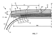
図6は、トレッド中央ゾーン25も、異なるゴム化合物を使用した2つの層を備える、別の実施形態を示す。上部中央層28は、下部中央層27において使用される下部中央化合物と異なり、さらに、上部ショルダー層22において使用される化合物とも異なる、上部中央層化合物を使用する。この実施形態において、中央及びショルダーゾーンの下部層には同じ化合物が使用されるが、トレッド全体にわたって異なる化合物とすることもできることが理解される。
FIG. 6 shows another embodiment in which the tread
図7は、中央ゾーン25が、異なるゴム化合物を使用した2つの層を備える点で図6に類似し、ここでは、図5に示される上部層の構成を含む、別の実施形態を示す。
FIG. 7 is similar to FIG. 6 in that the
図6及び7は、図4及び5に示される構成に基づくものと同じ原理を例示するが、任意の他の構成を適用することができることが明らかであるべきである。 6 and 7 illustrate the same principles as those based on the configuration shown in FIGS. 4 and 5, but it should be clear that any other configuration can be applied.
図8は、中央ゾーン25が、異なるゴム化合物を使用する2つの層を備える点で図6に類似するが、中央及びショルダーゾーン内の下部層が、トレッド溝の底部よりも高く到達するように厚く作製される、別の実施形態を示す。境界は、トレッド溝の底部から2mm〜5mm半径方向外側に位置付けられる。
FIG. 8 is similar to FIG. 6 in that the
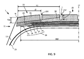
図9は、中央ゾーン25が、その全厚さにわたって同じゴム化合物を使用する点で図5に類似するが、下部ショルダー層が、距離L2にわたってエッジNから内方に(赤道面EPに向かって)延在する別のゴム化合物を使用する、別の実施形態を示す。
FIG. 9 is similar to FIG. 5 in that the
ここでも、図面は、異なるゾーン及び化合物の構成のうちの限定された数の実施例のみを例示する。例えば、例示される要素を修正することによって、または異なる図面上に分離して示される要素を組み合わせることによって、多くの他の構成が可能である。同じく前に説明したように、本発明によるタイヤは、対称である場合もあり、またはそうでない場合もあり、すなわち、本発明によるタイヤは、その赤道面EPのいずれかの側のタイヤ半部の両方が同じ構成を有する場合があり、またはそうでない場合もある。 Again, the drawings illustrate only a limited number of examples of different zone and compound configurations. Many other configurations are possible, for example, by modifying the illustrated elements or by combining the elements shown separately on different drawings. As also explained before, a tire according to the invention may or may not be symmetrical, i.e., a tire according to the invention may have a tire half on either side of its equatorial plane EP. Both may have the same configuration or not.
しかしながら、本発明によれば、距離L1は、転がりトレッド幅RTWの15%〜40%で構成され、上部ショルダー層22は、距離L1の少なくとも80%にわたってトレッド深さTDの70%〜130%の厚さを有する。
However, according to the present invention, the distance L1 is comprised between 15% and 40% of the rolling tread width RTW, and the
本発明によれば、下部ショルダー層は、エッジ(N)から軸方向内方に距離L2延在し、距離L2は、転がりトレッド幅RTWよりも15%超長く、下部ショルダー層は、ベルトパッケージを覆うショルダーゾーンの部分にわたって少なくとも4mmの厚さを有する。 According to the present invention, the lower shoulder layer extends a distance L2 inward in the axial direction from the edge (N), the distance L2 being more than 15% longer than the rolling tread width RTW, and the lower shoulder layer forming the belt package. It has a thickness of at least 4 mm over the portion of the shoulder zone to cover.
本発明によれば、上部ショルダーゴム化合物は、少なくとも1.3Mpaの50%歪み(G*50)において複素動的剪断弾性率を有し、また、少なくとも0.12の最大tan(δ)を有する。 According to the present invention, the upper shoulder rubber compound has a complex dynamic shear modulus at 50% strain (G * 50) of at least 1.3 Mpa and has a maximum tan (δ) of at least 0.12. .
本発明によれば、中央ゾーンにおいて地面に接触することを意図するゴム化合物は、最大で0.09の最大tan(δ)を有する。 According to the invention, rubber compounds intended to contact the ground in the central zone have a maximum tan (δ) of at most 0.09.
本発明によれば、下部ショルダーゴム化合物は、中央ゾーンにおいて地面に接触することを意図するゴム化合物の最大tan(δ)を超えない最大tan(δ)を有する。 According to the invention, the lower shoulder rubber compound has a maximum tan (δ) not exceeding the maximum tan (δ) of the rubber compound intended to contact the ground in the central zone.
本発明によるタイヤは、耐摩耗性及び転がり抵抗に関して本明細書の前文において説明される性能の妥協の打開を示す。 The tire according to the invention shows a breakthrough in the performance trade-offs described in the preamble of the present description in terms of wear resistance and rolling resistance.
中央ゾーン及び下部ショルダー層に使用されるゴム化合物は、天然ゴムに基づくこと、または大部分がシス1,4鎖である合成ポリイソプレン、及び場合により、少なくとも1つの他のジエンエラストマー、ならびに
−(i)沈降もしくは焼成シリカ、アルミナ、またはアルミノシリケートによって形成された群から選択され、120〜200m2/gの比表面積を有し、0phr〜70phrの添加量で使用される、SiOH及び/またはAlOH表面官能基を有するシリカ及び/またはアルミナ系の白色充填剤か、または
−(ii)充填剤の全体的な添加量が40phr〜70phrである、0phr以上かつ25phr以下の添加量において20〜120m2/gのCTAB比表面積を有するカーボンブラックと、(i)に記載された白色充填剤とのブレンド、のいずれかからなる補強充填剤に基づくことができる。
The rubber compound used for the central zone and the lower shoulder layer may be based on natural rubber or synthetic polyisoprene mostly cis 1,4 chain, and optionally at least one other diene elastomer, and-( i) SiOH and / or AlOH surface selected from the group formed by precipitated or calcined silica, alumina, or aluminosilicate, having a specific surface area of 120-200 m2 / g and used at an added amount of 0 phr-70 phr (I) a silica and / or alumina white filler having a functional group, or (ii) 20 to 120 m2 / g at an addition amount of 0 phr or more and 25 phr or less, wherein the total amount of the filler is 40 phr to 70 phr. A carbon black having a CTAB specific surface area of Blend of white filler, it can be based on the reinforcing filler consisting of either.
CTAB比表面積は、AFNOR規格NFT45−007(1987年11月、方法B)に従って決定される。 The CTAB specific surface area is determined according to AFNOR standard NFT45-007 (November 1987, Method B).
透明な充填剤または白色の充填剤が使用される場合、当業者に知られている薬剤から選択される、カップリング剤及び/または被覆剤を使用しなければならない。言及することができる好ましいカップリング剤の例としては、ビス−(3−トリアルコキシルイルプロピル)ポリスルフィド型の硫化アルコキシシラン、及び特に、純粋な液体製品の場合は、Si69の商標名で、また、固体製品の場合は、X50Sの商標名(N330ブラックと50/50の重量で配合される)でDegussaにより市販されている、ビス(3−トリエトキシルイルプロピル)テトラスルフィドが挙げられる。言及することができる被覆剤の例としては、脂肪族アルコール、Si116及びSi216の商標名でそれぞれDegussaにより市販されているヘキサデシルトリメトキシまたはトリエトキシシラン等のアルキルアルコキシシラン、ジフェニルグアニジン、ポリエチレングリコール、及び必要に応じてOHもしくはアルコキシ官能基で修飾されたシリコン油が挙げられる。被覆剤及び/またはカップリング剤は、充填剤に対して重量で1/100〜20/100の比率で、好ましくは、透明な充填剤が補強充填剤の全体を形成する場合には2/100〜15/100で、補強充填剤がカーボンブラック及び透明な充填剤のブレンドで形成される場合には1/100〜20/100で使用される。 If clear or white fillers are used, coupling and / or coating agents must be used, selected from the agents known to those skilled in the art. Examples of preferred coupling agents which may be mentioned are the sulfurized alkoxysilanes of the bis- (3-trialkoxylylpropyl) polysulfide type, and in particular, in the case of pure liquid products, under the trade name Si69; For solid products, mention may be made of bis (3-triethoxylylpropyl) tetrasulfide marketed by Degussa under the trade name X50S (compounded with N330 black by 50/50 by weight). Examples of coatings that may be mentioned are: aliphatic alcohols, alkylalkoxysilanes such as hexadecyltrimethoxy or triethoxysilane marketed by Degussa under the trade names Si116 and Si216, respectively, diphenylguanidine, polyethylene glycol, And silicone oils optionally modified with OH or alkoxy functions. The coating and / or coupling agent is in a ratio of 1/100 to 20/100 by weight relative to the filler, preferably 2/100 when the transparent filler forms the whole of the reinforcing filler. 1515/100, if the reinforcing filler is formed of a blend of carbon black and a transparent filler, it is used in a ratio of 1/100 to 20/100.
上で説明したシリカ及び/またはアルミナ型の材料のモルフォロジならびにSiOH及び/またはAlOH表面官能基を有し、これら材料の完全なまたは部分的な代替物として本発明に従って使用するのに適した、言及することができる補強充填剤の他の例としては、合成中に、炉に供給される油へのシリコン及び/もしくはアルミニウムの化合物の添加により、または合成後に、ケイ酸ナトリウム及び/もしくはアルミネートの溶液のカーボンブラックの水性懸濁液への酸の添加により、カーボンブラックの表面の少なくとも一部をSiOH及び/またはAlOH官能基で覆うことによって改質されるカーボンブラックを挙げることができる。SiOH及び/またはAlOH表面官能基を有するこの種類の炭酸化充填剤の言及できるいくつかの非限定的な例としては、1997年5月6〜9日のACS Meeting,Rubber Division,Anaheim,Calif.の会議番号24において説明され、また、欧州特許出願公開第EP−A−0 799 854号に記載された、CSDP充填剤が挙げられる。 The morphology of the silica and / or alumina type materials described above and the SiOH and / or AlOH surface functional groups which are suitable for use in accordance with the invention as a complete or partial replacement of these materials. Other examples of reinforcing fillers that can be used include the addition of compounds of silicon and / or aluminum to the oil supplied to the furnace during synthesis, or after synthesis, the sodium silicate and / or aluminate. Mention may be made of carbon blacks which are modified by the addition of an acid to the aqueous suspension of carbon black in solution, by covering at least a part of the surface of the carbon black with SiOH and / or AlOH functional groups. Some non-limiting examples of this type of carbonated filler having SiOH and / or AlOH surface functionalities include, but are not limited to, the ACS Meeting, Rubber Division, Anaheim, Calif., May 6-9, 1997. And CSDP fillers described in European Patent Application Publication No. EP-A-0 799 854.
透明な充填剤が、唯一の補強充填剤として使用される場合、ヒステリシス及び粘着性といった特性は、120〜180m2/gのCTAB比表面積を有する、沈降もしく焼成シリカ、または沈降アルミナまたはアルミノシリケートを使用することによって得られる。言及することができるこの種類の充填剤の非限定的ないくつかの例としては、Akzoによって市販されているKS404、Degussaによって市販されているUltrasil VN2またはVN3及びBV3370GR、Huberによって市販されているZeopol8745、Rhodiaによって市販されているZeosil175MPまたはZeosil11 65M、PPGによって市販されているHI−SIL 2000等が挙げられる。 If a transparent filler is used as the sole reinforcing filler, properties such as hysteresis and tackiness may be due to sedimented or calcined silica, or precipitated alumina or aluminosilicate, having a CTAB specific surface area of 120-180 m2 / g. Obtained by using. Some non-limiting examples of fillers of this type that may be mentioned include KS404 marketed by Akzo, Ultrasil VN2 or VN3 marketed by Degussa and BV3370GR, Zeopol 8745 marketed by Huber. Zeosil 175MP or Zeosil 1165M marketed by Rhodia, HI-SIL 2000 marketed by PPG, and the like.
天然ゴム、または大部分がシス−1,4鎖である合成ポリイソプレンとのブレンドに使用することができ、言及することができるジエンエラストマーのうち、好ましくは大部分がシス−1,4鎖であるポリブタジエン(BR)、スチレン−ブタジエンコポリマー(SBR)溶液もしくはエマルジョン、ブタジエン−イソプレンコポリマー(BIR)、またはスチレン−ブタジエン−イソプレンターポリマー(SBIR)を挙げることができる。これらエラストマーは、重合中に、または重合後に、ジビニルベンゼンまたは星形成剤等の分岐剤によって、または代替的に、例えばジメチルまたはジエチルアミノベンゾフェノンの作用によって鎖もしくは鎖の端にグラフトされる酸素化したカルボニル、カルボキシル官能基、もしくはアミン官能基を生じさせる官能化剤によって改質された、エラストマーとすることができる。天然ゴム、または大部分がシス1,4鎖である合成ポリイソプレンと、上で述べた1つまたは2つ以上のジエンエラストマーとのブレンドの場合、天然ゴムまたは合成ポリイソプレンは、好ましくは、主な比率で、より好ましくは、70phrを超える比率で使用される。 Of the diene elastomers that can be used and blended with natural rubber or synthetic polyisoprene that is predominantly cis-1,4 chain, preferably the majority are cis-1,4 chain. Certain polybutadienes (BR), styrene-butadiene copolymer (SBR) solutions or emulsions, butadiene-isoprene copolymers (BIR), or styrene-butadiene-isoprene terpolymers (SBIR) can be mentioned. These elastomers can be used to prepare, during or after the polymerization, oxygenated carbonyls which are grafted to the chain or chain ends by a branching agent such as divinylbenzene or a star-forming agent or, alternatively, by the action of, for example, dimethyl or diethylaminobenzophenone. , Carboxyl, or amine functional groups. In the case of a blend of natural rubber, or a synthetic polyisoprene predominantly cis 1,4 chain, with one or more of the diene elastomers described above, the natural rubber or synthetic polyisoprene preferably comprises And more preferably in a ratio above 70 phr.
例えば、トレッドが図2〜5のような2つのエラストマー化合物からなる構成において、それらの化合物は、下の表で説明されるようなものとすることができる。

損失因子「tan(δ)」は、ゴム化合物の動的特性である。この動的特性は、ASTM規格D5992−96に従って、粘度分析装置(Metravib VA4000)で測定される。各々厚さ2mm、直径1センチメートルの2つの円筒ペレットからなる試験片の応答を記録し(試験片は、試験片を形成することができるのに十分な厚さである領域内の赤道面の領域にできる限り近い、関係する層の高さの半分までタイヤから採取したサンプルで作製される)、試験片に、10Hzの振動数、60℃の温度で、単純交互正弦剪断応力を受けさせる。スイープは、0.1%から50%までのピークツーピーク(アウトバウンドサイクル)、次いで、50%から1%までのピークツーピーク(戻りサイクル)の変形の振幅をカバーする。本明細書で使用される結果は、損失係数tan(δ)及び複素動的剪断弾性率である。複素動的剪断弾性率は、試験中に印加される50%の歪みに関して「G*50」で示される。アウトバウンドサイクル中に、観察されるtan(δ)の最大値は、「最大tan(δ)」で示される。 The loss factor “tan (δ)” is a dynamic property of a rubber compound. This dynamic property is measured with a viscosity analyzer (Metravivb VA4000) according to ASTM standard D5992-96. The response of a test specimen consisting of two cylindrical pellets, each 2 mm thick and 1 cm in diameter, was recorded (the test specimen was measured at the equatorial plane in an area thick enough to form the test specimen). The specimen is subjected to a simple alternating sinusoidal shear stress at a frequency of 10 Hz and a temperature of 60 ° C., as close as possible to the area, made up of a sample taken from the tire to half the height of the layer concerned). The sweep covers the amplitude of the deformation from 0.1% to 50% peak-to-peak (outbound cycle), then from 50% to 1% peak-to-peak (return cycle). The results used herein are loss factor tan (δ) and complex dynamic shear modulus. The complex dynamic shear modulus is indicated by "G * 50" for a 50% strain applied during the test. During the outbound cycle, the maximum value of tan (δ) observed is denoted by “maximum tan (δ)”.
本発明の真の趣旨から逸脱することなく、様々な修正及び変更が本発明の実施形態に対して行われ得ることが、前述の説明から理解されるべきである。例えば、いくつかのゴム化合物の電気伝導の欠如のため、タイヤトレッドが、地面とタイヤリムとの間で静電気を伝導するための提供物を含み得ることがよく知られている。そのような提供物としては、この特定の目的のためにトレッドに挿入されている特定の化合物または層プロファイルを挙げることができる。そのような限定された変形物が、本発明の趣旨と矛盾しないこと、及び上の説明または添付の特許請求の範囲から本発明が認められる方法に影響を及ぼすべきではないことが理解される。 It should be understood from the foregoing description that various modifications and changes can be made to the embodiments of the present invention without departing from the true spirit of the invention. For example, due to the lack of electrical conduction of some rubber compounds, it is well known that tire treads may include provisions for conducting static electricity between the ground and the tire rim. Such donations may include certain compounds or layer profiles that have been inserted into the tread for this particular purpose. It is understood that such limited variations are not inconsistent with the spirit of the invention and should not affect the manner in which the invention is recognized from the above description or the appended claims.
Claims (13)
−前記上部ショルダー層が、トレッドエッジ(N、N’)から軸方向内方に距離L1延在し、前記距離L1が、前記転がりトレッド幅(RTW)の15%超え、かつ40%未満であり、
−前記上部ショルダー層が、前記距離L1の少なくとも80%にわたって、トレッド溝深さの70%〜130%の厚さ(T22)を有し、
−前記下部ショルダー層が、トレッドエッジ(N、N’)から軸方向内方に距離L2延在し、前記距離L2が、前記転がりトレッド幅(RTW)の15%を超え、
−前記下部ショルダー層が、前記ベルトパッケージを覆う前記ショルダーゾーンの部分にわたって、少なくとも4mmの厚さを有し、
−前記上部ショルダーゴム化合物が、少なくとも1.3MpaのG*50及び少なくとも0.12の最大tan(δ)を有し、
−前記下部ショルダーゴム化合物が、前記地面と接触することを意図する前記中央ゾーンの中央ゴム化合物の最大tan(δ)を超えない最大tan(δ)を有し、
−前記中央ゴム化合物が、最大で0.09の最大tan(δ)を有する、大型トラック用タイヤ。 A sub-casing, a belt package (19), and a rubber tread (2), wherein the tread extends from a first tread edge (N) to a second tread edge (N ') over a rolling tread width (RTW). Extending axially to the shoulder, said tread comprising a shoulder zone (21) adjacent each of said first and second edges, and a central zone (25) separating the two shoulder zones, wherein each shoulder zone Comprises a radial lower shoulder layer (24) and a radial upper shoulder layer (22), wherein the upper shoulder layer is intended to be in contact with the ground, wherein the lower shoulder layer comprises the belt package and the Interposed between the upper shoulder layer, the upper shoulder layer is made of an upper shoulder rubber compound, the lower shoulder layer, A large truck tire (1) comprising a lower shoulder rubber compound different from an upper shoulder rubber compound,
The upper shoulder layer extends axially inward from the tread edge (N, N ') a distance L1, the distance L1 being greater than 15% and less than 40% of the rolling tread width (RTW); ,
The upper shoulder layer has a thickness (T22) of 70% to 130% of the tread groove depth over at least 80% of the distance L1;
The lower shoulder layer extends axially inward from the tread edge (N, N ') a distance L2, wherein the distance L2 exceeds 15% of the rolling tread width (RTW);
The lower shoulder layer has a thickness of at least 4 mm over a part of the shoulder zone covering the belt package;
The upper shoulder rubber compound has a G * 50 of at least 1.3 Mpa and a maximum tan (δ) of at least 0.12;
- said lower shoulder rubber compound has a maximum tan ([delta]) not exceeding the maximum tan ([delta]) of the central rubber compound of said central zone intended to be in contact with the ground,
A heavy truck tire, wherein the central rubber compound has a maximum tan (δ) of at most 0.09.
Applications Claiming Priority (3)
| Application Number | Priority Date | Filing Date | Title |
|---|---|---|---|
| PCT/US2015/067663 WO2017116393A1 (en) | 2015-12-28 | 2015-12-28 | Heavy truck tire |
| USPCT/US2015/067663 | 2015-12-28 | ||
| PCT/US2016/067707 WO2017116834A1 (en) | 2015-12-28 | 2016-12-20 | Heavy truck tire |
Publications (3)
| Publication Number | Publication Date |
|---|---|
| JP2018538200A JP2018538200A (en) | 2018-12-27 |
| JP2018538200A5 JP2018538200A5 (en) | 2019-08-15 |
| JP6636161B2 true JP6636161B2 (en) | 2020-01-29 |
Family
ID=55300761
Family Applications (1)
| Application Number | Title | Priority Date | Filing Date |
|---|---|---|---|
| JP2018533100A Active JP6636161B2 (en) | 2015-12-28 | 2016-12-20 | Heavy truck tires |
Country Status (5)
| Country | Link |
|---|---|
| US (1) | US11254166B2 (en) |
| EP (1) | EP3397510B1 (en) |
| JP (1) | JP6636161B2 (en) |
| CN (1) | CN108698450B (en) |
| WO (2) | WO2017116393A1 (en) |
Families Citing this family (5)
| Publication number | Priority date | Publication date | Assignee | Title |
|---|---|---|---|---|
| US11383561B2 (en) * | 2017-12-21 | 2022-07-12 | Compagnie Generale Des Etablissements Michelin | Crown architecture of an electrically conductive tire for a civil engineering vehicle |
| US20210031565A1 (en) * | 2018-01-25 | 2021-02-04 | Compagnie Generale Des Etablissements Michelin | Tire with a Tread Sub-Layer Containing Multiple Materials |
| WO2020005280A1 (en) * | 2018-06-29 | 2020-01-02 | Compagnie Generale Des Etablissements Michelin | Improved tread wear profile with siped center region |
| JP7132113B2 (en) * | 2018-12-14 | 2022-09-06 | 株式会社ブリヂストン | tire |
| JP2022143272A (en) * | 2021-03-17 | 2022-10-03 | 住友ゴム工業株式会社 | tire |
Family Cites Families (25)
| Publication number | Priority date | Publication date | Assignee | Title |
|---|---|---|---|---|
| JPS55140605A (en) * | 1979-04-18 | 1980-11-04 | Bridgestone Corp | Tread sheath for large radial tire |
| JPS5850883B2 (en) * | 1979-12-31 | 1983-11-12 | 東洋ゴム工業株式会社 | A pneumatic tire with a tread made of at least two types of rubber |
| US5883179A (en) | 1995-10-25 | 1999-03-16 | The Yokohama Rubber Co., Ltd. | Rubber composition comprising carbon black surface treated with silica |
| JPH1178417A (en) * | 1997-09-04 | 1999-03-23 | Toyo Tire & Rubber Co Ltd | Pneumatic tire |
| JP4000276B2 (en) * | 2002-04-18 | 2007-10-31 | 株式会社ブリヂストン | Pneumatic tire |
| EP1479537A3 (en) * | 2003-05-13 | 2005-02-02 | Sumitomo Rubber Industries Limited | Pneumatic tire |
| JP4525010B2 (en) * | 2003-07-11 | 2010-08-18 | 横浜ゴム株式会社 | Pneumatic tire |
| US7222651B2 (en) * | 2003-10-27 | 2007-05-29 | Treadfx, Llc | Tire for preventing rollover or oversteer of a vehicle |
| US8408246B2 (en) * | 2005-10-05 | 2013-04-02 | Societe Bic | Fuel cartridge for fuel cells |
| JP4420098B2 (en) * | 2006-11-06 | 2010-02-24 | 横浜ゴム株式会社 | Pneumatic tire |
| WO2008111556A1 (en) * | 2007-03-08 | 2008-09-18 | Bridgestone Corporation | Pneumatic tire for two-wheeled motor vehicle |
| AU2008365894B2 (en) * | 2008-12-29 | 2012-04-12 | Compagnie Generale Des Etablissements Michelin | Heavy vehicle treads/undertread |
| FR2943951B1 (en) * | 2009-04-07 | 2012-12-14 | Michelin Soc Tech | TIRE FOR HEAVY VEHICLES HAVING A LAYER OF CIRCUMFERENTIAL REINFORCING ELEMENTS. |
| US8844595B2 (en) * | 2010-11-30 | 2014-09-30 | The Goodyear Tire & Rubber Company | Pneumatic tire with tread including tread base layer and tread blocks having two different rubber layers |
| US8720508B2 (en) * | 2011-03-17 | 2014-05-13 | Michelin Recherche Et Technique S.A. | Tread having a gradient of properties for improving irregular wear |
| FR2983122B1 (en) * | 2011-11-29 | 2014-01-03 | Michelin Soc Tech | PNEUMATIC COMPRISING A TREAD TAPE CONSISTING OF SEVERAL ELASTOMERIC MIXTURES |
| FR2983777B1 (en) * | 2011-12-09 | 2014-03-07 | Michelin Soc Tech | PNEUMATIC COMPRISING A LAYER OF CIRCUMFERENTIAL REINFORCING ELEMENTS |
| JP5457484B2 (en) * | 2012-02-27 | 2014-04-02 | 住友ゴム工業株式会社 | Heavy duty pneumatic tire |
| FR2992895B1 (en) * | 2012-07-05 | 2014-08-15 | Michelin & Cie | PNEUMATIC COMPRISING A TREAD TAPE CONSISTING OF SEVERAL ELASTOMERIC MIXTURES |
| FR2999117B1 (en) * | 2012-12-10 | 2015-01-16 | Michelin & Cie | PNEUMATIC COMPRISING A TREAD TAPE CONSISTING OF SEVERAL ELASTOMERIC MIXTURES |
| FR2999116B1 (en) * | 2012-12-10 | 2015-01-16 | Michelin & Cie | PNEUMATIC COMPRISING A TREAD TAPE CONSISTING OF SEVERAL ELASTOMERIC MIXTURES |
| DE102013103367A1 (en) * | 2013-04-04 | 2014-10-09 | Continental Reifen Deutschland Gmbh | Vehicle tires |
| US9352615B2 (en) * | 2013-10-22 | 2016-05-31 | The Goodyear Tire & Rubber Company | Pneumatic tire with multi-tread cap |
| DE102014209059A1 (en) * | 2014-05-14 | 2015-11-19 | Continental Reifen Deutschland Gmbh | Vehicle tires |
| US9809058B2 (en) * | 2014-08-27 | 2017-11-07 | The Goodyear Tire & Rubber Company | Tire with rubber tread of intermedial and lateral zones with path of least electrical resistance |
-
2015
- 2015-12-28 WO PCT/US2015/067663 patent/WO2017116393A1/en active Application Filing
-
2016
- 2016-12-20 EP EP16822594.4A patent/EP3397510B1/en active Active
- 2016-12-20 CN CN201680076956.7A patent/CN108698450B/en active Active
- 2016-12-20 US US16/066,850 patent/US11254166B2/en active Active
- 2016-12-20 WO PCT/US2016/067707 patent/WO2017116834A1/en unknown
- 2016-12-20 JP JP2018533100A patent/JP6636161B2/en active Active
Also Published As
| Publication number | Publication date |
|---|---|
| EP3397510B1 (en) | 2019-10-09 |
| WO2017116834A1 (en) | 2017-07-06 |
| CN108698450A (en) | 2018-10-23 |
| EP3397510A1 (en) | 2018-11-07 |
| US20190001751A1 (en) | 2019-01-03 |
| CN108698450B (en) | 2019-10-15 |
| WO2017116393A1 (en) | 2017-07-06 |
| JP2018538200A (en) | 2018-12-27 |
| US11254166B2 (en) | 2022-02-22 |
Similar Documents
| Publication | Publication Date | Title |
|---|---|---|
| JP6636161B2 (en) | Heavy truck tires | |
| US6959744B2 (en) | Tire with rubber tread of diverse zoned rubber compositions | |
| EP1231080A1 (en) | Tire with reinforced rubber sidewall | |
| EP1033265A2 (en) | Tire with reinforced rubber sidewall | |
| US10099513B2 (en) | Tire comprising a tread made up of several elastomeric compounds | |
| US10040318B2 (en) | Tire with rubber tread of intermedial and lateral zones | |
| WO2018118479A1 (en) | Heavy truck tire | |
| CN108367615B (en) | Tire with improved wear and rolling resistance performance | |
| US20180126785A1 (en) | Tire Comprising Working Layers Formed by Individual Wires | |
| US10442247B2 (en) | Tire comprising a layer of circumferential reinforcement elements | |
| EP2990226B1 (en) | Tire with circumferentially zoned tread including stratified lateral zones and peripheral sidewall extension zones | |
| US20170197469A1 (en) | Tire Comprising A Layer Of Circumferential Reinforcing Elements | |
| CN108472997B (en) | Tire with improved wear and rolling resistance performance | |
| CN108367620B (en) | Tire with improved wear and rolling resistance performance | |
| CN109476190B (en) | Tire with reduced weight bead area | |
| CN109311354B (en) | Heavy load tire | |
| CN108367610B (en) | Tire with improved wear and rolling resistance performance | |
| CN108367605B (en) | Tire with improved wear and rolling resistance performance | |
| CN108367617B (en) | Tire with improved wear and rolling resistance performance | |
| CN108367616B (en) | Tire with improved wear and rolling resistance performance | |
| CN108290451B (en) | Tire with improved wear and rolling resistance performance | |
| CN108290448B (en) | Tire with improved wear and rolling resistance performance | |
| WO2020005280A1 (en) | Improved tread wear profile with siped center region | |
| CN108367600B (en) | Tire with improved wear and rolling resistance performance | |
| CN108367608B (en) | Tire with improved wear and rolling resistance performance |
Legal Events
| Date | Code | Title | Description |
|---|---|---|---|
| A621 | Written request for application examination |
Free format text: JAPANESE INTERMEDIATE CODE: A621 Effective date: 20180622 |
|
| A131 | Notification of reasons for refusal |
Free format text: JAPANESE INTERMEDIATE CODE: A131 Effective date: 20190610 |
|
| A524 | Written submission of copy of amendment under article 19 pct |
Free format text: JAPANESE INTERMEDIATE CODE: A524 Effective date: 20190703 |
|
| A131 | Notification of reasons for refusal |
Free format text: JAPANESE INTERMEDIATE CODE: A131 Effective date: 20190819 |
|
| A521 | Request for written amendment filed |
Free format text: JAPANESE INTERMEDIATE CODE: A523 Effective date: 20190920 |
|
| TRDD | Decision of grant or rejection written | ||
| A01 | Written decision to grant a patent or to grant a registration (utility model) |
Free format text: JAPANESE INTERMEDIATE CODE: A01 Effective date: 20191118 |
|
| A61 | First payment of annual fees (during grant procedure) |
Free format text: JAPANESE INTERMEDIATE CODE: A61 Effective date: 20191217 |
|
| R150 | Certificate of patent or registration of utility model |
Ref document number: 6636161 Country of ref document: JP Free format text: JAPANESE INTERMEDIATE CODE: R150 |
|
| R250 | Receipt of annual fees |
Free format text: JAPANESE INTERMEDIATE CODE: R250 |
|
| R250 | Receipt of annual fees |
Free format text: JAPANESE INTERMEDIATE CODE: R250 |