JP6628570B2 - Lamp, lighting device, and light source module arrangement state determination method - Google Patents
Lamp, lighting device, and light source module arrangement state determination method Download PDFInfo
- Publication number
- JP6628570B2 JP6628570B2 JP2015224076A JP2015224076A JP6628570B2 JP 6628570 B2 JP6628570 B2 JP 6628570B2 JP 2015224076 A JP2015224076 A JP 2015224076A JP 2015224076 A JP2015224076 A JP 2015224076A JP 6628570 B2 JP6628570 B2 JP 6628570B2
- Authority
- JP
- Japan
- Prior art keywords
- light source
- arrangement
- hole
- led module
- frame
- Prior art date
- Legal status (The legal status is an assumption and is not a legal conclusion. Google has not performed a legal analysis and makes no representation as to the accuracy of the status listed.)
- Active
Links
- 238000000034 method Methods 0.000 title claims description 11
- 230000008569 process Effects 0.000 claims description 5
- 238000012790 confirmation Methods 0.000 claims description 3
- 230000000149 penetrating effect Effects 0.000 claims 1
- 239000000758 substrate Substances 0.000 description 70
- 238000010586 diagram Methods 0.000 description 64
- 230000000694 effects Effects 0.000 description 28
- 238000005286 illumination Methods 0.000 description 8
- 230000000630 rising effect Effects 0.000 description 4
- 239000002390 adhesive tape Substances 0.000 description 3
- 238000005520 cutting process Methods 0.000 description 3
- 238000007689 inspection Methods 0.000 description 3
- 230000002093 peripheral effect Effects 0.000 description 3
- 239000000853 adhesive Substances 0.000 description 2
- 230000001070 adhesive effect Effects 0.000 description 2
- 238000005452 bending Methods 0.000 description 2
- 230000002349 favourable effect Effects 0.000 description 2
- 238000004519 manufacturing process Methods 0.000 description 2
- 239000000463 material Substances 0.000 description 2
- 238000007639 printing Methods 0.000 description 2
- 230000005540 biological transmission Effects 0.000 description 1
- 238000010276 construction Methods 0.000 description 1
- 238000006073 displacement reaction Methods 0.000 description 1
- 239000011521 glass Substances 0.000 description 1
- 238000003780 insertion Methods 0.000 description 1
- 230000037431 insertion Effects 0.000 description 1
- 230000007246 mechanism Effects 0.000 description 1
- 239000002184 metal Substances 0.000 description 1
- 238000000465 moulding Methods 0.000 description 1
- 230000003287 optical effect Effects 0.000 description 1
- 230000002265 prevention Effects 0.000 description 1
- 230000009467 reduction Effects 0.000 description 1
- 239000011347 resin Substances 0.000 description 1
- 229920005989 resin Polymers 0.000 description 1
- 238000004904 shortening Methods 0.000 description 1
- XLYOFNOQVPJJNP-UHFFFAOYSA-N water Substances O XLYOFNOQVPJJNP-UHFFFAOYSA-N 0.000 description 1
Images


Description
本発明は、光源が実装された長尺形状の灯具と、この灯具を取り付ける照明器具とを有する照明装置に関する。特に、灯具における光源の良好な配置を確認する技術に関する。 The present invention relates to a lighting device having a long lamp having a light source mounted thereon and a lighting fixture to which the lamp is attached. In particular, the present invention relates to a technique for confirming a favorable arrangement of a light source in a lamp.
従来、光源が実装された長尺状の灯部と、この灯具の一部が挿入される凹部を有する照明器具とを備える照明装置であって、灯具が照明器具に着脱自在に取り付けられる照明装置がある(例えば、特許文献1〜3参照)。
2. Description of the Related Art Conventionally, there is provided a lighting device including a long lamp portion on which a light source is mounted and a lighting device having a recess into which a part of the lamp is inserted, wherein the lighting device is detachably attached to the lighting device. (For example, see
従来、照明装置に用いられる灯具は、光源を覆うカバーが装着された後には、光源の配置が良好であるか確認ができなかった。
特許文献1〜3に記載された構成によって、光源を良好に配置することは可能であるが、複雑な成形と複雑な作業を要していた。
Conventionally, in a lamp used for a lighting device, after a cover for covering a light source is attached, it was not possible to confirm whether the arrangement of the light source is good.
With the configurations described in
本発明は光源の配置が良好であるかどうかを容易に確認できる灯具の提供を目的とする。 An object of the present invention is to provide a lamp which can easily confirm whether or not the arrangement of the light source is good.
この発明の灯具は、
光源が実装された光源モジュールと、
前記光源モジュールが配置された基台と
を有し、
前記基台は、
前記光源モジュールの配置が許容される許容配置領域内に、前記光源モジュールによって覆われた状態から、前記基台に対する前記光源モジュールの配置状態を検出する貫通孔が形成されたことを特徴とする。
The lamp of the present invention
A light source module on which a light source is mounted,
A base on which the light source module is arranged,
The base is
In a permissible arrangement area where the arrangement of the light source modules is permitted, a through hole for detecting an arrangement state of the light source modules with respect to the base from a state covered by the light source modules is formed.
本発明によれば、灯具の備える基台には、光源モジュールの配置状態を検出する貫通孔が形成されているので、光源の配置が良好であるかどうかを容易に確認できる。 According to the present invention, since the through-hole for detecting the arrangement state of the light source module is formed in the base provided in the lamp, it is possible to easily confirm whether the arrangement of the light source is good.
以下、本発明の実施の形態について、図面を用いて説明する。なお、以下に説明する実施の形態によって本発明が限定されない。また、以下の図面では各構成部の大きさの関係が実際のものとは異なる場合がある。また、実施の形態の説明において、「上」、「下」、「左」、「右」、「前」、「後」、「表」、「裏」といった方向や位置が示されている場合、それらの表記は、説明の便宜上、そのように記載しているだけであって、装置、器具、部品等の配置や向き等を限定しない。 Hereinafter, embodiments of the present invention will be described with reference to the drawings. The present invention is not limited by the embodiments described below. Further, in the following drawings, the size relationship of each component may be different from the actual one. In the description of the embodiments, directions and positions such as “up”, “down”, “left”, “right”, “front”, “rear”, “front”, and “back” are indicated. These notations are merely described for convenience of explanation, and do not limit the arrangement, orientation, and the like of the devices, instruments, parts, and the like.
実施の形態1.
実施の形態1で説明する灯具(光源ユニットと記す場合がある)は、光源が実装された光源モジュールと、光源モジュールが配置された基台(フレームとも呼ばれる)とを有する。そして、基台は、光源モジュールの配置が許容される許容配置領域内に、光源モジュールによって覆われた状態から、基台に対する光源モジュールの配置状態を検出する貫通孔が形成されている。以下の実施の形態では、「許容配置領域内」は、灯具の短手方向を例とした場合、光源モジュールの設計上の基板幅に対して、寸法+W5、寸法−W5の範囲を許容配置領域内として説明している。
以下では、光源モジュールの配置状態を検出する貫通孔を貫通孔Hと記す。貫通孔Hはそのバリエーションに応じて、貫通孔H1、貫通孔H2等のように記す場合がある。
以下の実施の形態1では、フレームに形成された貫通孔Hと、フレームに配置された光源モジュールとの配置関係に関して、実施例1〜実施例5の5つの実施例を説明する。貫通孔Hの態様として(正方形を含む)長方形を例示しているが、これに限らず、多角形、(楕円形を含む)円形、星形など、さまざまな形を選択することができる。実施例1から実施例5のそれぞれのフレームを、フレーム110−1〜110−5と記す。
また、実施例6として、フレームから切り起こして形成した突部によってできた貫通孔を、貫通孔Hとして用いる例を説明する。
なお、実施の形態1〜4では光源モジュールとして光源にLEDを用いたLEDモジュールを例に説明するが、光源モジュールの光源はLEDに限らず、有機ELあるいはレーザなどの発光素子でもよい。
さらに、光源ユニット、照明器具、および照明装置は、いずれも長尺形状の例を用いて説明するが、長尺形状に限らず、正方形、円形、多角形といった形状であっても本願発明が適用できる。
The lamp described in Embodiment 1 (sometimes referred to as a light source unit) includes a light source module on which a light source is mounted and a base (also called a frame) on which the light source module is arranged. In the base, a through hole is formed in an allowable arrangement area in which the arrangement of the light source modules is allowed, for detecting an arrangement state of the light source modules with respect to the base from a state covered by the light source modules. In the following embodiments, “in the allowable arrangement area” refers to the width of the dimension + W5 and the dimension −W5 with respect to the designed board width of the light source module when the short direction of the lamp is taken as an example. It is described as inside.
Hereinafter, the through hole for detecting the arrangement state of the light source module is referred to as a through hole H. The through-hole H may be described as a through-hole H1, a through-hole H2, or the like according to the variation.
In the following first embodiment, five examples of Examples 1 to 5 will be described with respect to an arrangement relationship between a through hole H formed in a frame and a light source module arranged in the frame. Although a rectangle (including a square) is illustrated as an example of the through-hole H, the present invention is not limited to this, and various shapes such as a polygon, a circle (including an ellipse), and a star can be selected. The respective frames of the first to fifth embodiments are referred to as frames 110-1 to 110-5.
Further, as a sixth embodiment, an example will be described in which a through hole formed by a protrusion formed by cutting and raising the frame is used as the through hole H.
In the first to fourth embodiments, an LED module using an LED as a light source is described as an example of the light source module. However, the light source of the light source module is not limited to the LED, and may be a light emitting element such as an organic EL or a laser.
Further, the light source unit, the lighting fixture, and the lighting device will be described using an example of a long shape, but the invention is not limited to the long shape, and the present invention is applicable to a shape such as a square, a circle, and a polygon. it can.
(実施例1)
<***構成の説明***>
図1〜図12を参照して、実施の形態1における実施例1の照明装置10を説明する。
(Example 1)
<*** Configuration description ***>
With reference to FIG. 1 to FIG. 12, the
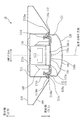
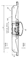
図1は、照明装置10の斜視図である。
図2は、照明装置10の内部を示す図であり、図1のA−A断面図である。
図3は、照明装置10を光源ユニット100と照明器具200とに分解した分割斜視図である。
図4は、光源ユニット100を取付側から見た斜視図である。
図5は、光源ユニット100の分解斜視図であり、フレーム110−1,LEDモジュール120,カバー130を示しており、電源装置140、取付具150等は省略している。
図5には貫通孔H1、H2を示した。光源ユニット100の長手方向にそろって並ぶ貫通孔Hを、それそれぞれ貫通孔H1、H2と表記している。
図6は、光源ユニット100の5面図である。
図7は、光源ユニット100の端部を示す部分拡大図である。
図7に示すように、カバー130で光源モジュールがおおわれている光源ユニット100の完成状態において、取付側から貫通孔H1、H2を介して光源モジュールの配置状態を確認できる。このためカバー130を取り除いて確認する等の手間がいらない。
図8は、フレーム110−1及びLEDモジュール120を示す図であり、照射側を示す図である。
図9は、フレーム110−1及びLEDモジュール120を示す図であり、取付側を示す図である。
図10は、図8のA−A断面図である。
FIG. 1 is a perspective view of the
FIG. 2 is a diagram illustrating the inside of the
FIG. 3 is an exploded perspective view in which the
FIG. 4 is a perspective view of the
FIG. 5 is an exploded perspective view of the
FIG. 5 shows the through holes H1 and H2. The through holes H aligned in the longitudinal direction of the
FIG. 6 is a five-side view of the
FIG. 7 is a partially enlarged view showing an end portion of the
As shown in FIG. 7, in the completed state of the
FIG. 8 is a diagram illustrating the frame 110-1 and the
FIG. 9 is a diagram illustrating the frame 110-1 and the
FIG. 10 is a sectional view taken along line AA of FIG.
<照明装置10>
実施の形態1の照明装置10は、天井や壁などの取付部に取り付けられる照明装置であり、長手方向に延びた長尺状の照明装置である。
照明装置10は、長手方向に複数連結して用いられる場合がある。
照明装置10は、光源ユニット100(灯具と呼ぶ場合がある)と、光源ユニット100を着脱可能に取り付ける照明器具200とを有する。
<
The
The
The
<光源ユニット100>
図4、図5等に示すように、
光源ユニット100は、
プレート110−1、LEDモジュール120、カバー130、電源装置140、2つの取付具150を有する。
<
As shown in FIGS.
The
It has a plate 110-1, an
<フレーム110−1>
図5に示すように、フレーム110−1は長手方向に延びた板状であり、発光素子120aが実装された基板120bが取り付けられる基板取付面部111aを有する。基板取付面部111aには貫通孔Hが形成されている。また、フレーム110−1は、短手方向の端部に、基板取付面部111aから立ち上がる立上部112を備える。立上部112の先端は図10のようにカール形状のカール部112cが形成されている。
<Frame 110-1>
As shown in FIG. 5, the frame 110-1 has a plate shape extending in the longitudinal direction, and has a substrate mounting surface 111a to which a
フレーム110−1は、長尺状の平板である平面部111と、平面部111の短手方向の両端が折り曲げられて形成される立上部112とを有し、短手方向に切る断面が略コ字形状である。
The frame 110-1 has a flat portion 111 that is a long flat plate, and a rising
<LEDモジュール120>
基板取付面部111aには、LEDである発光素子120aが実装された基板120bを備えるLEDモジュール120が取り付けられる。また、図4のように、基板取付面部111aの裏面である装置取付面部111dには、LEDモジュール120に電力を供給する電源装置140と、2つの取付具150とが取り付けられる。
<
The
<電源装置140>
電源装置140は、平面部111の長手方向中央より一方側に寄せて取り付けられている。なお、電源装置140は、平面部111の長手方向中央に取り付けられていても構わない。
<
The
<取付具150>
図4のように、2つの取付具150は、平面部111の長手方向の両端側にそれぞれ取り付けられている。取付具150は、後述する照明器具200が備える板バネ230と係合し、光源ユニット100を照明器具200に固定する。さらに、取付具150は、光源ユニット100の形状に応じて設置される数が変更することができる。光源ユニット100の長手方向の長さが短い場合は、長手方向の一端部のみに取付具150を設置し他端部はフックなどで固定する機構としてもよい。また、光源ユニット100の長手方向の長さが長い場合は、長手方向の両端部と中央部に取付具150を設置してもよい。中央部に取付具150を設置する場合は、取付具150および取付具150に対応し照明器具200に配置され板バネ230が、電源装置140と干渉しない位置を選択する。
<Mounting
As shown in FIG. 4, the two
<カバー130>
カバー130は、基板120bを覆う。また、カバー130は、長手方向に延びたカバー側部131を有する。カバー130は、カバー側部131がフレーム110−1の短手方向の端部であるフレーム側部110aを覆ってフレーム110−1に取り付けられる。
図5に示すように、カバー130は、フレーム110−1に取り付けられたLEDモジュール120を覆うようにフレーム110−1に取り付けられる。立上部112にはカバー130の取付側の端部が取り付けられ、カバー130がフレーム110−1に固定される。カバー130は長手方向の両端を塞ぐ一対のカバー蓋部134を有する。
<Cover 130>
The
As shown in FIG. 5, the
<照明器具200の説明>
図1のように、照明器具200は、器具本体210と、器具本体210の両端部に取り付けられる端板部220とを備える。器具本体210は、コの字状に折り曲げられて形成され、長手方向に延びた凹部211(図2)を備える。器具本体210は、板金が折り曲げられて形成される。
<Description of
As shown in FIG. 1, the
図2及び図6に示すように、凹部211は、長手方向に延びた底面部211aと、底面部211aの短手方向の両端部を基端部として立ち上がる側面部211bとを備える。また、凹部211は、側面部211bの先端部を開口縁部211baとする開口部211cが形成される。また、器具本体210は、開口縁部211baから取付側に向かって広がるように形成された傾斜部211dを備える。
As shown in FIGS. 2 and 6, the
<板バネ230>
凹部211の底面部211aには、端子台240と、2つの板バネ230が設置される。端子台240は、電源端子台である。あるいは、端子台240は信号端子台でも構わない。板バネ230は、上述した光源ユニット100が備える取付具150に対応する位置に配置される。また、図2に示すように、光源ユニット100が照明器具200に取り付けられた状態では、光源ユニット100が備える電源装置140の少なくとも一部が開口部211cから凹部211に挿入される。
なお、板バネ230は、照明器具200の形状に応じて設置される数が変更することができる。照明器具200の長手方向の長さが短い場合は、長手方向の一端部のみに板バネ230を設置し他端部はフックなどで固定する機構としてもよい。
また、照明器具200の長手方向の長さが長い場合は、長手方向の両端部と中央部に板バネ230を設置してもよい。中央部に板バネ230を設置する場合は、板バネ230および板バネ230に対応する光源ユニット100が備える取付具150が、光源ユニット100に取り付けられる電源装置140と干渉しない位置を選択する。
<
A
The number of the
When the length of the
<端子台240>
図示はないが、端子台240には外部電源に接続される電源電線が接続される。また、図示はないが、端子台240には照明器具200を長手方向に連結した場合に隣接する照明器具に電力や信号を送る送り電線が接続される。よって、凹部211内には、電源電線や送り電線等が配設される。
<Terminal block 240>
Although not shown, a power supply wire connected to an external power supply is connected to the
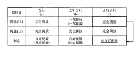
図11,12を参照して、実施例1におけるフレームに形成された貫通孔H1、H2と、フレームに配置された光源モジュールとの配置関係を説明する。図11は実施例1の構成と、その作用及び効果を説明する図である。図11(a)〜(c)の上側は、図8のA−A断面図に相当し、下側は図9に相当する。図11では人の視線90を示している。後述の実施例2〜5も同様である。
With reference to FIGS. 11 and 12, the positional relationship between the through holes H1 and H2 formed in the frame and the light source modules disposed in the frame according to the first embodiment will be described. FIG. 11 is a diagram illustrating the configuration of the first embodiment, and its operation and effects. 11A to 11C correspond to the AA cross-sectional view of FIG. 8, and the lower side corresponds to FIG. FIG. 11 shows a line of
図11において、
(a)はLEDモジュール120の基準配置(良好配置)の様子を示す図、
(b)はLEDモジュール120の許容配置(良好配置)の様子を示す図、
(c)はLEDモジュール120非良好配置の様子を示す図である。
図12は、(a)から(c)のLEDモジュール120配置の様子を纏めた一覧表である。
In FIG.
(A) is a diagram showing a state of a reference arrangement (good arrangement) of the
(B) is a diagram showing a state of an allowable arrangement (good arrangement) of the
(C) is a figure which shows a mode of
FIG. 12 is a list summarizing the arrangement of the
<LEDモジュール120の基準配置>
図11(a)の基準配置は、以下の様である。
貫通孔H1:向かって左側
貫通孔H2:向かって右側
W1:
(1)LEDモジュール120(基板120b)の幅寸法(短手方向の長さ寸法)と、
(2)貫通孔H1の最外縁と貫通孔H2の最外縁との距離と
の両者の寸法である。
つまり、LEDモジュール120(基板120b)の幅寸法は、貫通孔H1の最外縁と貫通孔H2の最外縁との距離と、略同じ長さである。
W2:貫通孔H1の最内縁と貫通孔H2の最内縁との距離
W3:フレーム110−1の短手方向の中心C1から貫通孔H1の最外縁と貫通孔H2の最外縁までの距離
2×W3=W1(W3=W1÷2)
W4:フレーム110−1の短手方向の中心C1から貫通孔H1の最内縁と貫通孔H2の最内縁までの距離
2×W4=W2(W4=W2÷2)
W5:貫通孔H1及び貫通孔H2における、最外縁と最内縁との距離、短手方向における貫通孔H1及び貫通孔H2の長さ寸法
W4+W5=W3(W5=W3−W4)
<Reference arrangement of
The reference arrangement in FIG. 11A is as follows.
Through hole H1: left side facing Through hole H2: right side facing W1:
(1) The width dimension (length dimension in the lateral direction) of the LED module 120 (
(2) The distance between the outermost edge of the through hole H1 and the outermost edge of the through hole H2.
That is, the width dimension of the LED module 120 (
W2: distance between the innermost edge of the through hole H1 and the innermost edge of the through hole H2 W3: distance from the center C1 in the lateral direction of the frame 110-1 to the outermost edge of the through hole H1 and the outermost edge of the through
W4: distance from the center C1 in the short direction of the frame 110-1 to the innermost edge of the through hole H1 and the innermost edge of the through
W5: distance between the outermost edge and the innermost edge of the through hole H1 and the through hole H2, the length dimension of the through hole H1 and the through hole H2 in the short direction W4 + W5 = W3 (W5 = W3-W4)
LEDモジュール120の基準配置は、LEDモジュール120の短手方向の中心C2とフレーム110−1の短手方向の中心C1とが一致して重なった状態である。この状態で、LEDモジュール120(基板120b)の短手方向の両端部は、貫通孔H1及び貫通孔H2の最外縁の直上に位置し、貫通孔H1及び貫通孔H2は、フレーム110−1の照射側に載置されたLEDモジュール120によって、完全に閉塞されている。灯具の基準構造体であるフレーム110−1にLEDモジュール120が基準配置された状態では、発光素子(LED)が良好に配置されており(良好配置の状態)、良好な灯具である。
The reference arrangement of the
<LEDモジュール120の許容配置>
図11(b)の許容配置は、以下の様である。
ΔW1:フレーム110−1の短手方向の中心C1を基準としたLEDモジュール120(基板120b)の短手方向の偏移量
ΔW1≦W5
W6=W3+ΔW1(ΔW1=W6−W3)
W7=W3−ΔW1(ΔW1=W3−W7)
W6=W7+(2×ΔW1)
W6+W7=W2
<Allowable arrangement of
The allowable arrangement in FIG. 11B is as follows.
ΔW1: shift amount in the short direction of the LED module 120 (
W6 = W3 + ΔW1 (ΔW1 = W6-W3)
W7 = W3-ΔW1 (ΔW1 = W3-W7)
W6 = W7 + (2 × ΔW1)
W6 + W7 = W2
LEDモジュール120の許容配置は、フレーム110−1の短手方向の中心C1を基準としてLEDモジュール120の短手方向の中心C2が許容値(W5)以下の範囲で偏移した状態である。この状態で、LEDモジュール120(基板120b)の短手方向の右側端部は、貫通孔H2の最外縁より内側に配置される。貫通孔H1は、フレーム110−1の照射側に載置されたLEDモジュール120によって完全に閉塞されている。貫通孔H2は、フレーム110−1の照射側に載置されたLEDモジュール120によって不完全に閉塞されており(貫通孔H2の一部が開放されており)、LEDモジュール120(基板120b)の短手方向の右側端部は貫通孔H2と重なっている。灯具の基準構造体であるフレーム110−1にLEDモジュール120が許容配置された状態では、発光素子(LED)が短手方向に許容値(W5)以下の範囲で偏移して配置(良好に配置)されており(良好配置の状態)、良好な灯具である。
The allowable arrangement of the
<LEDモジュール120の非良好配置>
図11(c)の非良好配置は、以下の様である。
ΔW2:フレーム110−1の短手方向の中心C1を基準としたLEDモジュール120(基板120b)の短手方向の偏移量
ΔW2>W5
W8=W3+ΔW2(ΔW2=W8−W3)
W9=W3−ΔW2(ΔW2=W3−W9)
W8=W9+(2×ΔW2)
W8+W9=W1
<
The poor arrangement in FIG. 11 (c) is as follows.
ΔW2: the amount of shift of the LED module 120 (
W8 = W3 + ΔW2 (ΔW2 = W8−W3)
W9 = W3-ΔW2 (ΔW2 = W3-W9)
W8 = W9 + (2 × ΔW2)
W8 + W9 = W1
LEDモジュール120の非良好配置は、フレーム110−1の短手方向の中心C1を基準としてLEDモジュール120の短手方向の中心C2が許容値(W5)を超えた範囲で偏移した状態である。この状態で、LEDモジュール120(基板120b)の短手方向の右側端部は貫通孔H2の最内縁より内側に配置される。貫通孔H1は、フレーム110−1の照射側に載置されたLEDモジュール120によって完全に閉塞されている。貫通孔H2は、フレーム110−1の照射側に載置されたLEDモジュール120によって閉塞されず完全に開放されており)、LEDモジュール120(基板120b)の短手方向の右側端部は貫通孔H2から確認できない。灯具の基準構造体であるフレーム110−1にLEDモジュール120が非良好配置された状態では、発光素子(LED)が短手方向に許容値(W5)を超えた範囲で偏移して配置(非良好に配置)されており(非良好配置の状態)、良好な灯具ではない。
The poor arrangement of the
<***実施例1の効果***>
このように、実施例1では、灯具の基準構造体であるフレーム110−1に対してLEDモジュール120(基板120b)が短手方向に偏移した状態のうち、フレーム110−1の短手方向に形成された一対(2つ)の貫通孔のうちいずれかが完全に開放された場合のみを、LEDモジュール120(基板120b)が非良好配置の灯具であると判定できる。実施例1では、フレーム110−1の短手方向に形成された一対(2つ)の貫通孔は、フレーム110−1の取付側から貫通しているので、フレーム110−1の取付側に部品の取付けを行う時、フレーム110−1にカバーが取り付けられて光源ユニット100の組立が完了した後でも、良好/非良好の判定を行うことができる。このため、非良好の状態で後工程の組立作業が継続されたり、非良好の光源ユニット100は出荷されたりするおそれがない。
<**** Effects of Example 1 ***>
As described above, in the first embodiment, in the state where the LED module 120 (the
以上のように、実施例1のフレーム(基台)は、一対の貫通孔H1、H2が形成されており、光源ユニット(灯具)は、いずれか一方の貫通孔がLEDモジュールで覆われていない開放状態の場合に、LEDモジュールの配置状態が良好ではないことが検出される。 As described above, the frame (base) according to the first embodiment has the pair of through holes H1 and H2 formed therein, and the light source unit (the lamp) does not have any one of the through holes covered with the LED module. In the case of the open state, it is detected that the arrangement state of the LED modules is not good.
(実施例2)
図13,14を参照して実施例2を説明する。
図13は、実施例2における貫通孔H3の構成と、その作用及び効果を説明する図である。実施例2では、主に、実施例1と異なる点について説明する。実施例2において、実施例1と同様の構成部については同一の符号を付し、その説明を省略する。
(Example 2)
Second Embodiment A second embodiment will be described with reference to FIGS.
FIG. 13 is a diagram illustrating the configuration of the through hole H3 according to the second embodiment, and the operation and effect thereof. In the second embodiment, mainly the points different from the first embodiment will be described. In the second embodiment, the same components as those in the first embodiment are denoted by the same reference numerals, and description thereof will be omitted.
図13に示すように、フレーム110−2及びLEDモジュール120の、図8におけるA−A断面図である。
(a)はLEDモジュール120の基準配置(良好配置)の様子を示す図、
(b)はLEDモジュール120の許容配置(良好配置)の様子を示す図、
(c)はLEDモジュール120非良好配置の様子を示す図、
である。
図14は、(a)から(c)のLEDモジュール120配置の様子を纏めた一覧表である。
13 is a cross-sectional view of the frame 110-2 and the
(A) is a diagram showing a state of a reference arrangement (good arrangement) of the
(B) is a diagram showing a state of an allowable arrangement (good arrangement) of the
(C) is a diagram showing a state of poorly arranged
It is.
FIG. 14 is a list summarizing the arrangement of the
実施例2のフレーム110−2には貫通孔H3が形成されている。貫通孔H3は、実施例1における貫通孔H1と貫通孔H2とを繋いで一つの貫通孔H3として形成されている。 A through hole H3 is formed in the frame 110-2 of the second embodiment. The through hole H3 is formed as one through hole H3 by connecting the through hole H1 and the through hole H2 in the first embodiment.
<LEDモジュール120の基準配置>
図13(a)の基準配置は、以下の様である。
貫通孔H3:中央部に一つ
W1:LEDモジュール120(基板120b)の幅寸法(短手方向の長さ寸法)
W2:フレーム110−2の短手方向における貫通孔H3の長さ寸法
W3:フレーム110−2の短手方向の中心C1からLEDモジュール120(基板120b)の短手方向の両端部までの距離
2×W3=W1(W3=W1÷2)
W4:フレーム110−2の短手方向の中心C1から貫通孔H3の短手方向の両最外縁までの距離(左右両最外縁間の長さ寸法)
2×W4=W2(W4=W2÷2)
W5:フレーム110−2の短手方向における、貫通孔H3各端部とLEDモジュール120(基板120b)の各端部との距離
W4+W5≦W3(W5≦W3−W4)
<Reference arrangement of
The reference arrangement in FIG. 13A is as follows.
Through hole H3: one at the center W1: width of LED module 120 (
W2: Length dimension of through hole H3 in the short direction of frame 110-2 W3: Distance from center C1 in the short direction of frame 110-2 to both ends in the short direction of LED module 120 (
W4: Distance from the center C1 in the short direction of the frame 110-2 to both outermost edges in the short direction of the through hole H3 (length dimension between left and right outermost edges)
2 × W4 = W2 (W4 = W2 ÷ 2)
W5: distance between each end of the through hole H3 and each end of the LED module 120 (
LEDモジュール120の基準配置は、LEDモジュール120の短手方向の中心C2とフレーム110−2の短手方向の中心C1とが一致して重なった状態である。この状態で、LEDモジュール120(基板120b)の短手方向の各端部は貫通孔H3の最外縁よりW5だけ外側(短手方向の中心からW5だけ多く離れた位置)に配置される。貫通孔H3は、フレーム110−2の照射側に載置されたLEDモジュール120によって完全に閉塞されている。灯具の基準構造体であるフレーム110−2にLEDモジュール120が基準配置された状態では、発光素子(LED)が良好に配置されており(良好配置の状態)、良好な灯具である。
The reference arrangement of the
<LEDモジュール120の許容配置>
図13(b)の許容配置は、以下の様である。
ΔW1:フレーム110−2の短手方向の中心C1を基準としたLEDモジュール120(基板120b)の短手方向の偏移量
ΔW1≦W5
W6=W3+ΔW1(ΔW1=W6−W3)
W7=W3−ΔW1(ΔW1=W3−W7)
W6=W7+(2×ΔW1)
W6+W7=W1
<Allowable arrangement of
The allowed arrangement in FIG. 13B is as follows.
ΔW1: the amount of shift in the short direction of the LED module 120 (
W6 = W3 + ΔW1 (ΔW1 = W6-W3)
W7 = W3-ΔW1 (ΔW1 = W3-W7)
W6 = W7 + (2 × ΔW1)
W6 + W7 = W1
LEDモジュール120の許容配置は、フレーム110−2の短手方向の中心C1を基準としてLEDモジュール120の短手方向の中心C2が許容値(W5)以下の範囲で偏移した状態である。この状態で、LEDモジュール120(基板120b)の短手方向の両端部は貫通孔H3の各最外縁より外側に配置される(ΔW1≦W5)。灯具の基準構造体であるフレーム110−2にLEDモジュール120が許容配置された状態では、発光素子(LED)が短手方向に許容値(W5)以下の範囲で偏移して配置(良好に配置)されており(良好配置の状態)、良好な灯具である。
The allowable arrangement of the
<LEDモジュール120の非良好配置>
図13(c)の非良好配置は、以下の様である。
ΔW2:フレーム110−2の短手方向の中心C1を基準としたLEDモジュール120(基板120b)の短手方向の偏移量
ΔW2>W5
W8=W3+ΔW2(ΔW2=W8−W3)
W9=W3−ΔW2(ΔW2=W3−W9)
W8=W9+(2×ΔW2)
W8+W9=W1
<
The poor arrangement shown in FIG. 13C is as follows.
ΔW2: the amount of shift of the LED module 120 (
W8 = W3 + ΔW2 (ΔW2 = W8−W3)
W9 = W3-ΔW2 (ΔW2 = W3-W9)
W8 = W9 + (2 × ΔW2)
W8 + W9 = W1
LEDモジュール120の非良好配置は、フレーム110−2の短手方向の中心C1を基準としてLEDモジュール120の短手方向の中心C2が許容値(W5)を超えた範囲で偏移した状態である。この状態で、LEDモジュール120(基板120b)の短手方向の右側端部は貫通孔H3の右側の最外縁より内側に配置される。貫通孔H3は、フレーム110−2の照射側に載置されたLEDモジュール120によって不完全に閉塞されており(貫通孔H3の一部が開放されており)、LEDモジュール120(基板120b)の短手方向の右側端部は貫通孔H3と重なっている。灯具の基準構造体であるフレーム110−2にLEDモジュール120が非良好配置された状態では、発光素子(LED)が短手方向に許容値(W5)を超えた範囲で偏移して配置(非良好に配置)されており(非良好配置の状態)、良好な灯具ではない。
The poor arrangement of the
<***実施例2の効果***>
このように、実施例2では、灯具の基準構造体であるフレーム110−2に対して形成された一つ貫通孔によって実施例1と同様の効果を得ることができる。また、実施例2おける貫通孔H3は、実施例1の貫通孔H1,H2に比べて大きく形成されているので視認性に優れる。このため、灯具の良好/非良好の判定をより正確に実施することができる。
<**** Effect of Example 2 ***>
As described above, in the second embodiment, the same effect as in the first embodiment can be obtained by one through hole formed in the frame 110-2 which is the reference structure of the lamp. Further, since the through hole H3 in the second embodiment is formed larger than the through holes H1 and H2 in the first embodiment, the visibility is excellent. Therefore, it is possible to more accurately determine whether the lamp is good or bad.
以上のように、実施例2の光源ユニット(灯具)は、貫通孔H3にLEDモジュールで覆われていない開放状態の部分が有る場合に、開放状態の部分によってLEDモジュールの配置状態が良好ではないことが検出される。 As described above, in the light source unit (lamp) according to the second embodiment, when the through-hole H3 includes an open portion that is not covered with the LED module, the arrangement state of the LED module is not good due to the open portion. Is detected.
(実施例3)
図15,16を参照して実施例3を説明する。
図15は、実施例3における貫通孔H4、H5の構成と、その作用及び効果を説明する図である。実施例3では、主に、実施例1と異なる点について説明する。実施例3において、実施例1と同様の構成部については同一の符号を付し、その説明を省略する。
(Example 3)
Third Embodiment A third embodiment will be described with reference to FIGS.
FIG. 15 is a diagram illustrating the configuration of the through holes H4 and H5 according to the third embodiment, and the operation and effect thereof. In the third embodiment, the points different from the first embodiment will be mainly described. In the third embodiment, the same components as those in the first embodiment are denoted by the same reference numerals, and description thereof will be omitted.
図15において、
(a)はLEDモジュール120の基準配置(良好配置)の様子を示す図、
(b)はLEDモジュール120の許容配置(良好配置)の様子を示す図、
(c)はLEDモジュール120非良好配置の様子を示す図、
である。
図16は、(a)から(c)のLEDモジュール120配置の様子を纏めた一覧表である。
In FIG.
(A) is a diagram showing a state of a reference arrangement (good arrangement) of the
(B) is a diagram showing a state of an allowable arrangement (good arrangement) of the
(C) is a diagram showing a state of poorly arranged
It is.
FIG. 16 is a list summarizing the arrangement of the
<LEDモジュール120の基準配置>
図15(a)の基準配置は、以下の様である。
貫通孔H4:向かって左側
貫通孔H5:向かって右側
W1:
(1)W1は、LEDモジュール120(基板120b)の幅寸法(短手方向の長さ寸法)であり、
(2)W1は、貫通孔H4の最内縁と貫通孔H5の最内縁との距離でもある。
つまり、LEDモジュール120(基板120b)の幅寸法は、貫通孔H4の最内縁と貫通孔H5の最内縁との距離と、略同じ長さである。
W10:貫通孔H4の最外縁と貫通孔H5の最外縁との距離
W10=2×W11
W11:フレーム110−3の短手方向の中心C1から貫通孔H4,H5の短手方向の両最外縁までの距離
2×W11=W10(W11=W10÷2)
W3:W3は、フレーム110−3の短手方向の中心C1から貫通孔H4の最内縁と貫通孔H5の最内縁までの距離
2×W3=W1(W3=W1÷2)
W5:貫通孔H4及び貫通孔H5における、最外縁と最内縁との距離であり、短手方向における貫通孔H4及び貫通孔H5の長さ寸法
W3+W5≦W11(W5≦W11−W3)
<Reference arrangement of
The reference arrangement in FIG. 15A is as follows.
Through hole H4: left side as viewed Through hole H5: right side as viewed W1:
(1) W1 is the width dimension (length dimension in the lateral direction) of the LED module 120 (
(2) W1 is also the distance between the innermost edge of the through hole H4 and the innermost edge of the through hole H5.
That is, the width dimension of the LED module 120 (
W10: distance between the outermost edge of through-hole H4 and the outermost edge of through-hole H5 W10 = 2 × W11
W11: distance from the center C1 in the short direction of the frame 110-3 to the outermost edges in the short direction of the through holes H4 and
W3: W3 is the distance from the center C1 in the short direction of the frame 110-3 to the innermost edge of the through-hole H4 and the innermost edge of the through-hole H5. 2 × W3 = W1 (W3 = W1 ÷ 2)
W5: The distance between the outermost edge and the innermost edge of the through hole H4 and the through hole H5, and the length dimension of the through hole H4 and the through hole H5 in the lateral direction W3 + W5 ≦ W11 (W5 ≦ W11−W3)
LEDモジュール120の基準配置は、LEDモジュール120の短手方向の中心C2とフレーム110−3の短手方向の中心C1とが一致して重なった状態である。この状態で、LEDモジュール120(基板120b)の短手方向の両端部は貫通孔H4及び貫通孔H5の最内縁より内側(短手方向の中心に接近した位置)に配置される。貫通孔H4及び貫通孔H5は、フレーム110−3の照射側に載置されたLEDモジュール120によって閉塞されることがなく、完全に開放されている。灯具の基準構造体であるフレーム110−3にLEDモジュール120が基準配置された状態では、発光素子(LED)が良好に配置されており(良好配置の状態)、良好な灯具である。
The reference arrangement of the
<LEDモジュール120の許容配置>
図15(b)の許容配置は、以下の様である。
ΔW1:フレーム110−3の短手方向の中心C1を基準としたLEDモジュール120(基板120b)の短手方向の偏移量
ΔW1≦W5
W6=W3+ΔW1(ΔW1=W6−W3)
W7=W3−ΔW1(ΔW1=W3−W7)
W6=W7+(2×ΔW1)
W6+W7=W1
<Allowable arrangement of
The allowable arrangement in FIG. 15B is as follows.
ΔW1: the amount of deviation of the LED module 120 (
W6 = W3 + ΔW1 (ΔW1 = W6-W3)
W7 = W3-ΔW1 (ΔW1 = W3-W7)
W6 = W7 + (2 × ΔW1)
W6 + W7 = W1
LEDモジュール120の許容配置は、フレーム110−3の短手方向の中心C1を基準としてLEDモジュール120の短手方向の中心C2が許容値(W5)以下の範囲で偏移した状態である。この状態で、LEDモジュール120(基板120b)の短手方向の左側端部は貫通孔H4の最内縁より外側に配置される。貫通孔H4は、フレーム110−3の照射側に載置されたLEDモジュール120によって不完全に閉塞されており(貫通孔H4の一部が開放されており)、LEDモジュール120(基板120b)の短手方向の左側端部は貫通孔H4と重なっている。貫通孔H5は、フレーム110−3の照射側に載置されたLEDモジュール120によって閉塞されることがなく、完全に開放されている。灯具の基準構造体であるフレーム110−3にLEDモジュール120が許容配置された状態では、発光素子(LED)が短手方向に許容値(W5)以下の範囲で偏移して配置(良好に配置)されており(良好配置の状態)、良好な灯具である。
The allowable arrangement of the
<LEDモジュール120の非良好配置>
図15(c)の非良好配置は、以下の様である。
ΔW2:フレーム110−3の短手方向の中心C1を基準としたLEDモジュール120(基板120b)の短手方向の偏移量
ΔW2>W5
W8=W3+ΔW2(ΔW2=W8−W3)
W9=W3−ΔW2(ΔW2=W3−W9)
W8=W9+(2×ΔW2)
W8+W9=W1
<
The poor arrangement in FIG. 15C is as follows.
ΔW2: deviation amount of the LED module 120 (
W8 = W3 + ΔW2 (ΔW2 = W8−W3)
W9 = W3-ΔW2 (ΔW2 = W3-W9)
W8 = W9 + (2 × ΔW2)
W8 + W9 = W1
LEDモジュール120の非良好配置は、フレーム110−3の短手方向の中心C1を基準としてLEDモジュール120の短手方向の中心C2が許容値(W5)を超えた範囲で偏移した状態である。この状態で、LEDモジュール120(基板120b)の短手方向の左側端部は貫通孔H4の最外縁より外側に配置される。貫通孔H4は、フレーム110−3の照射側に載置されたLEDモジュール120によって完全に閉塞されており、LEDモジュール120(基板120b)の短手方向の左側端部は貫通孔H4から確認できない。貫通孔H5は、フレーム110−3の照射側に載置されたLEDモジュール120によって閉塞されることがなく、完全に開放されている。灯具の基準構造体であるフレーム110−3にLEDモジュール120が非良好配置された状態では、発光素子(LED)が短手方向に許容値(W5)を超えた範囲で偏移して配置(非良好に配置)されており(非良好配置の状態)、良好な灯具ではない。
The poor arrangement of the
<***実施例3の効果***>
このように、実施例3では、灯具の基準構造体であるフレーム110−3に対してLEDモジュール120(基板120b)が短手方向に偏移した状態のうち、フレーム110−3の短手方向に形成された一対(2つ)の貫通孔のうちいずれかが完全に閉塞された場合のみを、LEDモジュール120(基板120b)が良好な配置ではない(非良好配置の)非良好な灯具であると判定することができる。また、実施例3における貫通孔H4,H5は、フレーム110−3の照射側にLEDモジュール120(基板120b)が基準配置された状態で、フレーム110−3の短手方向におけるLEDモジュール120(基板120b)の両端部の外側に配置される。つまり、貫通孔H4,H5は、フレーム110−3にLEDモジュール120を載置する際に位置決めのガイドとして機能するので、LEDモジュール120を基準配置しやすくなる。このため、灯具の品質を向上させることができる。
<*** Effect of Example 3 ***>
As described above, in the third embodiment, of the state in which the LED module 120 (the
以上のように実施例3のフレームは、一対の貫通孔H4、H5が形成されており、光源ユニット100(灯具)は、いずれか一方の貫通孔がLEDモジュールで覆われた閉塞状態の場合に、LEDモジュールの配置状態が良好ではないことが検出される。 As described above, the frame according to the third embodiment is formed with the pair of through holes H4 and H5, and the light source unit 100 (light) is closed when one of the through holes is covered with the LED module. It is detected that the arrangement state of the LED modules is not good.
(実施例4)
図17,18を参照して実施例4を説明する。
図17は、実施例4における貫通孔H6の構成と、その作用及び効果を説明する図である。実施例4では、主に、実施例1と異なる点について説明する。
実施例4では実施例1と同様の構成部については同一の符号を付し、その説明を省略する。
(Example 4)
Fourth Embodiment A fourth embodiment will be described with reference to FIGS.
FIG. 17 is a diagram illustrating the configuration of the through hole H6 according to the fourth embodiment, and the operation and effect thereof. In the fourth embodiment, the points that are different from the first embodiment will be mainly described.
In the fourth embodiment, the same components as those in the first embodiment are denoted by the same reference numerals, and description thereof will be omitted.
図17において、
(a)はLEDモジュール120の基準配置(良好配置)の様子を示す図、
(b)はLEDモジュール120の許容配置(良好配置)の様子を示す図、
(c)はLEDモジュール120非良好配置の様子を示す図、
である。
図18は、(a)から(c)のLEDモジュール120配置の様子を纏めた一覧表である。
In FIG.
(A) is a diagram showing a state of a reference arrangement (good arrangement) of the
(B) is a diagram showing a state of an allowable arrangement (good arrangement) of the
(C) is a diagram showing a state of poorly arranged
It is.
FIG. 18 is a list summarizing the arrangement of the
実施例4のフレーム110−4には貫通孔H6が形成されている。貫通孔H6は、実施例3における貫通孔H4と貫通孔H5とを繋いで一つの貫通孔として形成されている。 A through hole H6 is formed in the frame 110-4 of the fourth embodiment. The through hole H6 is formed as one through hole by connecting the through hole H4 and the through hole H5 in the third embodiment.
<LEDモジュール120の基準配置>
図17(a)の基準配置は、以下の様である。
貫通孔H6:中央部に一つ
W1:LEDモジュール120(基板120b)の幅寸法(短手方向の長さ寸法)
W10:フレーム110−4の短手方向における貫通孔H6の長さ寸法
W11:フレーム110−4の短手方向の中心C1から貫通孔H6の短手方向の両最外縁までの距離(左右両最外縁間の長さ寸法)
2×W11=W10(W11=W10÷2)
W3:フレーム110−4の短手方向の中心C1からLEDモジュール120(基板120b)の短手方向の両端部までの距離
2×W3=W1(W3=W1÷2)
W5:フレーム110−4の短手方向における、貫通孔H6各端部とLEDモジュール120(基板120b)の各端部との距離
W3+W5≦W11(W5≦W11−W3)
<Reference arrangement of
The reference arrangement in FIG. 17A is as follows.
Through hole H6: one at the center W1: width of LED module 120 (
W10: Length dimension of the through hole H6 in the short direction of the frame 110-4 W11: Distance from the center C1 in the short direction of the frame 110-4 to both outermost edges in the short direction of the through hole H6 (right and left both ends) Length between outer edges)
2 × W11 = W10 (W11 = W10 ÷ 2)
W3: distance from center C1 in the short direction of frame 110-4 to both ends in the short direction of LED module 120 (
W5: distance between each end of the through hole H6 and each end of the LED module 120 (
LEDモジュール120の基準配置は、LEDモジュール120の短手方向の中心C2とフレーム110−4の短手方向の中心C1とが一致して重なった状態である。
この状態で、LEDモジュール120(基板120b)の短手方向の各端部は貫通孔H6の最外縁よりW5だけ内側(短手方向の中心にW5だけ接近した位置)に配置される。貫通孔H6は、フレーム110−4の照射側に載置されたLEDモジュール120(基板120b)によって中央部が閉塞されており、基板120bの両端部より外側が開放している。
灯具の基準構造体であるフレーム110−4にLEDモジュール120が基準配置された状態では、発光素子(LED)が良好に配置されており(良好配置の状態)、良好な灯具である。
The reference arrangement of the
In this state, each short-side end of the LED module 120 (
In a state where the
<LEDモジュール120の許容配置>
図17(b)の許容配置は、以下の様である。
ΔW1:フレーム110−4の短手方向の中心C1を基準としたLEDモジュール120(基板120b)の短手方向の偏移量
ΔW1≦W5
W6=W3+ΔW1(ΔW1=W6−W3)
W7=W3−ΔW1(ΔW1=W3−W7)
W6=W7+(2×ΔW1)
W6+W7=W1
<Allowable arrangement of
17 (b) is as follows.
ΔW1: deviation amount of the LED module 120 (
W6 = W3 + ΔW1 (ΔW1 = W6-W3)
W7 = W3-ΔW1 (ΔW1 = W3-W7)
W6 = W7 + (2 × ΔW1)
W6 + W7 = W1
LEDモジュール120の許容配置は、フレーム110−4の短手方向の中心C1を基準としてLEDモジュール120の短手方向の中心C2が許容値(W5)以下の範囲で偏移した状態である。この状態で、LEDモジュール120(基板120b)の短手方向の両端部は貫通孔H6の各最外縁より内側に配置される(ΔW1≦W5)。灯具の基準構造体であるフレーム110−4にLEDモジュール120が許容配置された状態では、発光素子(LED)が短手方向に許容値(W5)以下の範囲で偏移して配置(良好に配置)されており(良好配置の状態)、良好な灯具である。
The allowable arrangement of the
<LEDモジュール120の非良好配置>
図17(c)の非良好配置は、以下の様である。
ΔW2:フレーム110−4の短手方向の中心C1を基準としたLEDモジュール120(基板120b)の短手方向の偏移量
ΔW2>W5
W8=W3+ΔW2(ΔW2=W8−W3)
W9=W3−ΔW2(ΔW2=W3−W9)
W8=W9+(2×ΔW2)
W8+W9=W1
<
The poor arrangement in FIG. 17 (c) is as follows.
ΔW2: amount of deviation of the LED module 120 (
W8 = W3 + ΔW2 (ΔW2 = W8−W3)
W9 = W3-ΔW2 (ΔW2 = W3-W9)
W8 = W9 + (2 × ΔW2)
W8 + W9 = W1
LEDモジュール120の非良好配置は、フレーム110−4の短手方向の中心C1を基準としてLEDモジュール120の短手方向の中心C2が許容値(W5)を超えた範囲で偏移した状態である。この状態で、LEDモジュール120(基板120b)の短手方向の左側端部は貫通孔H6の左側の最外縁より外側に配置される。貫通孔H6は、フレーム110−4の照射側に載置されたLEDモジュール120によって左側に片寄って閉塞され、貫通孔H6の右側のみが開放されており、LEDモジュール120(基板120b)の短手方向の右側端部のみが貫通孔H6と重なっている。灯具の基準構造体であるフレーム110−4にLEDモジュール120が非良好配置された状態では、発光素子(LED)が短手方向に許容値(W5)を超えた範囲で偏移して配置(非良好に配置)されており(非良好配置の状態)、良好な灯具ではない。
The poor arrangement of the
<***実施例4の効果***>
このように、実施例4では、灯具の基準構造体であるフレーム110−4に対して形成された一つ貫通孔によって実施例3と同様の効果を得ることができる。また、本実施例4における貫通孔H6は、実施例3の貫通孔H4,H5に比べて大きく形成されているので視認性に優れる。このため、灯具の良好/非良好の判定をより正確に実施することができる。
<*** Effect of Example 4 ***>
As described above, in the fourth embodiment, the same effect as in the third embodiment can be obtained by one through hole formed in the frame 110-4 which is the reference structure of the lamp. Further, since the through hole H6 in the fourth embodiment is formed larger than the through holes H4 and H5 in the third embodiment, the through hole H6 is excellent in visibility. Therefore, it is possible to more accurately determine whether the lamp is good or bad.
以上のように、実施例4の光源ユニット(灯具)は、貫通孔の周縁にLEDモジュールで覆われている閉塞状態の部分が有る場合に、閉塞状態の部分によってLEDモジュールの配置状態が良好ではないことが検出される。 As described above, in the light source unit (lamp) according to the fourth embodiment, when there is a portion in the closed state covered with the LED module on the periphery of the through hole, the arrangement state of the LED module is not good due to the closed portion. Not found.
(実施例5)
図19,20を参照して実施例5を説明する。
図19は、実施例5における貫通孔H7の構成と、その作用及び効果を説明する図である。実施例5では、主に、実施例1と異なる点について説明する。
(Example 5)
A fifth embodiment will be described with reference to FIGS.
FIG. 19 is a diagram illustrating the configuration of the through-hole H7 according to the fifth embodiment, and the operation and effect thereof. In the fifth embodiment, points different from the first embodiment will be mainly described.
図19は、フレーム110−5及びLEDモジュール120の、図8におけるA−A断面図である。
(a)は、LEDモジュール120の基準配置(良好配置)の様子を示す図、
(b)は、LEDモジュール120の許容配置(良好配置)の様子を示す図、
(c)は、LEDモジュール120の非良好配置の様子を示す図である。
図20は、(a)から(c)のLEDモジュール120配置の様子を纏めた一覧表である。
FIG. 19 is a cross-sectional view of the frame 110-5 and the
(A) is a diagram showing a state of a reference arrangement (good arrangement) of the
(B) is a diagram showing a state of an allowable arrangement (good arrangement) of the
(C) is a figure which shows the mode of the poor arrangement of the
FIG. 20 is a list summarizing the arrangement of the
実施例5に係るLEDモジュール120の基板120bの取付側には、識別用マークMが設けられている。実施例5の識別用マークMは、基板120bの取付側の任意の位置に、略正方形の表示印刷が任意の位置を取り囲む周辺領域とは異なる色調で施されている。周辺領域の色調が黒色、茶色、濃紺色、深緑などの暗い色調である場合には、表示印刷は白色、黄色、薄青色などの比較的明るい色調が選択される。また、周辺領域の色調が明るい色調である場合には、表示印刷は比較的暗い色調が選択される。
An identification mark M is provided on the mounting side of the
そして、実施例5におけるフレーム110−5には貫通孔H7が形成されている。貫通孔H7は、識別用マークMよりも大きい寸法で形成されている。 Further, a through hole H7 is formed in the frame 110-5 in the fifth embodiment. The through hole H7 is formed with a size larger than the identification mark M.
<LEDモジュール120の基準配置>
図19(a)の基準配置は、以下の様である。
識別用マークMは、基板120bの取付側に一つ設けられている。
貫通孔H7は、識別用マークMと重なる位置に一つ形成されている。
W1:基板120bの幅寸法(短手方向の長さ寸法)。
W12:フレーム110−5の短手方向における識別用マークMの長さ寸法
W15:フレーム110−5の短手方向の中心C1から識別用マークMの短手方向の最内縁までの距離
W16:フレーム110−5の短手方向の中心C1から識別用マークMの短手方向の最外縁までの距離
W12=W16−W15
W13:フレーム110−5の短手方向における貫通孔H7の長さ寸法
W14:フレーム110−5の短手方向の中心C1から貫通孔H7の短手方向の最内縁までの距離
W17:フレーム110−5の短手方向の中心C1から貫通孔H7の短手方向の最外縁までの距離
W13=W17−W15
W5:フレーム110−5の短手方向における、識別用マークMの最内縁と貫通孔H7の最内縁、及び識別用マークMの最外縁と貫通孔H7の最外縁との距離
W14+W5≧W15(W5≧W15−W14)
W16+W5≦W17(W5≦W17−W16)
<Reference arrangement of
The reference arrangement in FIG. 19A is as follows.
One identification mark M is provided on the mounting side of the
One through hole H7 is formed at a position overlapping the identification mark M.
W1: width of
W12: Length dimension of identification mark M in the short direction of frame 110-5 W15: Distance from center C1 in the short direction of frame 110-5 to innermost edge of identification mark M in the short direction W16: Frame Distance from the center C1 in the short direction of 110-5 to the outermost edge of the identification mark M in the short direction W12 = W16−W15
W13: Length dimension of through hole H7 in the short direction of frame 110-5 W14: Distance from center C1 in the short direction of frame 110-5 to innermost edge in the short direction of through hole H7 W17: Frame 110- 5 from the center C1 in the lateral direction to the outermost edge of the through hole H7 in the lateral direction W13 = W17−W15
W5: distance in the lateral direction of the frame 110-5 between the innermost edge of the identification mark M and the innermost edge of the through hole H7, and the distance between the outermost edge of the identification mark M and the outermost edge of the through hole H7 W14 + W5 ≧ W15 (W5 ≧ W15-W14)
W16 + W5 ≦ W17 (W5 ≦ W17−W16)
LEDモジュール120の基準配置は、LEDモジュール120の短手方向の中心C2とフレーム110−5短手方向の中心C1とが一致して重なった状態である。この状態で、識別用マークMはフレーム110−5の短手方向における貫通孔H7の略中心に配置される。識別用マークMの全体が貫通孔H7の内側に配置されており、識別用マークMの最内縁及び最外縁は貫通孔H7と重なっている。灯具の基準構造体であるフレーム110−5にLEDモジュール120が基準配置された状態では、発光素子(LED)が良好に配置されており(良好配置の状態)、良好な灯具である。
The reference arrangement of the
<LEDモジュール120の許容配置>
図19(b)の許容配置は、以下の様である。
ΔW1:フレーム110−5の短手方向の中心を基準としたLEDモジュール120(基板120b)の短手方向の偏移量
ΔW1≦W5
W16+ΔW1≦W17(ΔW1≦W17−W16)
W6=W3+ΔW1(ΔW1=W6−W3)
W7=W3−ΔW1(ΔW1=W3−W7)
W6=W7+(2×ΔW1)
W6+W7=W1
<Allowable arrangement of
The allowable arrangement in FIG. 19B is as follows.
ΔW1: shift amount in the short direction of the LED module 120 (
W16 + ΔW1 ≦ W17 (ΔW1 ≦ W17−W16)
W6 = W3 + ΔW1 (ΔW1 = W6-W3)
W7 = W3-ΔW1 (ΔW1 = W3-W7)
W6 = W7 + (2 × ΔW1)
W6 + W7 = W1
LEDモジュール120の許容配置は、フレーム110−5の短手方向の中心C1を基準としてLEDモジュール120の短手方向の中心C2が許容値(W5)以下の範囲で偏移した状態である。この状態で、識別用マークMの全体が貫通孔H7の内側に配置されており、識別用マークMの最内縁及び最外縁は貫通孔H7と重なっている。(ΔW1≦W5)。
灯具の基準構造体であるフレーム110−5にLEDモジュール120が許容配置された状態では、発光素子(LED)が短手方向に許容値(W5)以下の範囲で偏移して配置(良好に配置)されており(良好配置の状態)、良好な灯具である。
The allowable arrangement of the
In a state where the
<LEDモジュール120の非良好配置>
図19(c)の非良好配置は、以下の様である。
ΔW2:フレーム110−5の短手方向の中心C1を基準としたLEDモジュール120(基板120b)の短手方向の偏移量
ΔW2>W5
W16+ΔW2>W17(ΔW1=W17−W16)
W8=W3+ΔW2(ΔW2=W8−W3)
W9=W3−ΔW2(ΔW2=W3−W9)
W8=W9+(2×ΔW2)
W8+W9=W1
<
The poor arrangement shown in FIG. 19C is as follows.
ΔW2: the amount of shift of the LED module 120 (
W16 + ΔW2> W17 (ΔW1 = W17−W16)
W8 = W3 + ΔW2 (ΔW2 = W8−W3)
W9 = W3-ΔW2 (ΔW2 = W3-W9)
W8 = W9 + (2 × ΔW2)
W8 + W9 = W1
LEDモジュール120の非良好配置は、フレーム110−5の短手方向の中心C1を基準としてLEDモジュール120の短手方向の中心C2が許容値(W5)を超えた範囲で偏移した状態である。この状態で、識別用マークMの一部が貫通孔H7の内側に配置されており、識別用マークMの最内縁のみが貫通孔H7と重なっている。(ΔW1≦W5)。灯具の基準構造体であるフレーム110−5にLEDモジュール120が非良好配置された状態では、発光素子(LED)が短手方向に許容値(W5)を超えた範囲で偏移して配置(非良好に配置)されており(非良好配置の状態)、良好な灯具ではない。
The poor arrangement of the
<***実施例5の効果***>
このように、実施例5では、LEDモジュール120(基板120b)の取付側に敷設された識別用マークMと、灯具の基準構造体であるフレーム110−5に対して、識別用マークMdよりも大きい寸法で形成された一つ貫通孔とによって実施例1〜4と同様の効果を得ることができる。また、識別用マークMはLEDモジュール120(基板120b)の大きさや形状に影響されない任意の位置に敷設することができる。そして、貫通孔H7は識別用マークMと重なる位置でありフレーム110−5の大きさや形状に影響されない任意の位置に形成することができる。さらに、実施例5はフレーム110−5の長手方向におけるLEDモジュール120の配置について、良好な配置又は非良好な配置のいずれであるかを判定することができる。このため、灯具の良好/非良好の判定をより正確に実施することができる。
<*** Effect of Example 5 ***>
As described above, in the fifth embodiment, the identification mark M laid on the mounting side of the LED module 120 (the
実施例5のように、貫通孔H7は、識別マークMの少なくとも一部を露出させており、光源湯ユニット(灯具)は、識別マークMの露出状態によって、フレームに対するLEDモジュールの配置状態が検出される。 As in the fifth embodiment, the through hole H7 exposes at least a part of the identification mark M, and the light source hot water unit (lamp) detects the arrangement state of the LED module with respect to the frame based on the exposure state of the identification mark M. Is done.
<作用及び効果のまとめ>
実施例1〜5で説明した各構成、およびこれらを組み合わせることで、あらゆる向きにおいて、フレームに対するLEDモジュール(基板)の配置が、良好な配置又は非良好な配置のいずれであるかを判定することができる。
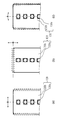
(1)図21(a)に示す、実施例1〜5で説明したフレームの短手方向におけるLEDモジュールの配置ついて、良好な配置又は非良好な配置のいずれであるかを判定することができる。
(2)また、図21(b)に示すフレームの長手方向におけるLEDモジュールの配置、また短手方向、長手方向の位置ずれが複合されたフレームの斜め方向におけるLEDモジュールの配置について、良好な配置又は非良好な配置のいずれであるかを判定することができる。
(3)さらに図21(c)に示すフレームの回転方向におけるLEDモジュールの配置について、良好な配置又は非良好な配置のいずれであるかを判定することもできる。
<Summary of actions and effects>
It is possible to determine whether the arrangement of the LED module (substrate) with respect to the frame is a good arrangement or an unfavorable arrangement in all directions by combining the configurations described in the first to fifth embodiments and combinations thereof. Can be.
(1) It is possible to determine whether the arrangement of the LED modules in the lateral direction of the frame described in the first to fifth embodiments shown in FIG. .
(2) In addition, the arrangement of the LED modules in the longitudinal direction of the frame shown in FIG. 21 (b) and the arrangement of the LED modules in the oblique direction of the frame in which the lateral and longitudinal displacements are combined are good. Alternatively, it can be determined whether the arrangement is a poor arrangement.
(3) Further, it is also possible to determine whether the LED module is arranged in a good or bad manner in the rotation direction of the frame shown in FIG.
このようにして、灯具の良好/非良好の判定を正確に実施することができる。なお、好ましくは、実施例1〜5において、LEDモジュールの配置を確認した結果、フレームに設けられた貫通孔の一部が開放する場合は、貫通孔を粘着テープなどで封止する。この際、粘着テープは電線の固定を兼ねるなど、他の機能と兼用したものであってもよい。LEDモジュールの配置の確認は、灯具の組立工程、出荷検査、納品(受入)検査、施工前検査などで実施することができる。 In this way, it is possible to accurately determine whether the lamp is good or bad. Preferably, in Examples 1 to 5, when the arrangement of the LED modules is confirmed, if a part of the through hole provided in the frame is opened, the through hole is sealed with an adhesive tape or the like. At this time, the adhesive tape may also be used for other functions such as fixing the electric wire. Confirmation of the arrangement of the LED modules can be performed in a lamp assembly process, shipping inspection, delivery (acceptance) inspection, pre-construction inspection, and the like.
識別マークMは、LEDモジュール120(基板120b)の大きさや形状に影響されない任意の位置に敷設することができ、貫通孔H7は識別マークMと重なる位置でありフレーム110−5の大きさや形状に影響されない任意の位置に形成することができるので、LEDモジュールの配置を確認した結果、フレームに設けられた貫通孔が完全に閉塞されるように位置を決定することができる。このため、貫通孔を粘着テープなどで封止する必要がなくなる。
The identification mark M can be laid at any position that is not affected by the size or shape of the LED module 120 (
(実施例6)
図22を参照して実施例6を説明する。
図22は、実施例6における光源ユニット100の部分拡大斜視図である。
(Example 6)
A sixth embodiment will be described with reference to FIG.
FIG. 22 is a partially enlarged perspective view of the
図22(a)はフレーム110−6からL字形状の突部115を切り起こした状態を示し、図22(b)はフレーム110−6から山型形状の突部116を切り起こした状態を示している。
FIG. 22A shows a state in which an L-shaped
実施例1〜5では、フレームに貫通孔Hを形成して、基板120bの配置を確認している。実施例6では、フレームの一部を取付側に切り起こすことによって形成された貫通孔を、基板120bの配置確認用の貫通孔Hとして用いる。実施例6では、実施例1と組み合わせた二つの例として図22(a)(b)を示している。切り起こされた突部115,116は、フレームの取付側に配置されるバネ取付金具、電源装置、配線固定具などの取付けに用いられる。フレーム110−6は、フレーム110−6以外の構造体が取り付けられることによって剛性が増すので,灯具の強度が向上する。
In Examples 1 to 5, the through holes H are formed in the frame, and the arrangement of the
以上、実施例1〜6を説明したが、以下のような場合に特に有用である。
接着剤を用いてフラットな面にLEDモジュールを接着固定する灯具において、生産(組立)時間を短縮させることを目的として接着剤が完全に固化することを待たずに灯具の組立を順次行う過程では、LEDモジュールがずれてしまうおそれがある。このような工程に本実施の形態1の構成あるいは方法を用いることで、カバーが取り付けられた後であっても、LEDモジュールの位置決めに頼らずに、光源が良好な位置に配置された灯具のみを確実に選択することができる。よって、非良好に配置された非良好な灯具の次工程への流出を防止しすることが可能であり、非良好な灯具が誤って出荷されることを防止することができる。
Although the first to sixth embodiments have been described above, they are particularly useful in the following cases.
In the process of successively assembling the lamps without waiting for the adhesive to completely solidify for the purpose of shortening the production (assembly) time for the lamps in which the LED module is adhered and fixed to the flat surface using the adhesive, Therefore, there is a possibility that the LED module is shifted. By using the configuration or method of the first embodiment in such a process, even after the cover is attached, only the lamp in which the light source is arranged in a favorable position without depending on the positioning of the LED module Can be reliably selected. Therefore, it is possible to prevent the unsatisfactoryly arranged lamps from flowing out to the next process, thereby preventing the unsatisfactory lamps from being shipped by mistake.
実施の形態2.
図23〜図29を参照して実施の形態2を説明する。実施の形態2では、実施の形態1の照明装置10に対して長さが略2倍の照明装置10Aを説明する。実施の形態2では、主に、実施の形態1と異なる点について説明する。
実施の形態1の光源ユニット100では、1枚の基板120bからなるLEDモジュール120が基板取付面部111aに取り付けられていた。実施の形態2では、長手方向に連結された2つのLEDモジュール1201,1202を取り付ける光源ユニット100Aと、光源ユニット100Aが取り付けられた照明器具200Aとを備える照明装置10Aについて説明する。本実施の形態において、実施の形態1と同様の構成については同一の符号を付し、その説明を省略する。
In the
実施の形態2の概要を説明する。 An outline of the second embodiment will be described.
図23は照明装置10Aの斜視図である。
図24は照明装置10Aの分解斜視図である。
図25は光源ユニット100Aの斜視図である。
図26は光源ユニット100Aの端部と中央部を示す部分拡大図である。
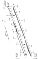
図27はフレーム100−7とLEDモジュール1201、1202とを示す図であり、照射側から見た図である。
図28は図27を取付側から見た図である。
図29は図27のA−A断面図である。
FIG. 23 is a perspective view of the
FIG. 24 is an exploded perspective view of the
FIG. 25 is a perspective view of the
FIG. 26 is a partially enlarged view showing the end and the center of the
FIG. 27 is a diagram illustrating the frame 100-7 and the
FIG. 28 is a diagram of FIG. 27 viewed from the mounting side.
FIG. 29 is a sectional view taken along line AA of FIG.
<照明装置10A>
照明装置10Aは、照明器具200Aと光源ユニット100Aとを備える。光源ユニット100Aには、長手方向に連結された2つのLEDモジュール1201,1202を取り付ける。したがって、照明装置10Aは、長手方向の長さが実施の形態1の照明装置10の約2倍である。照明装置10Aの長さの具体例は概ね8フィートである。
<
The
<光源ユニット100A、照明器具200A>
図26〜図28に示すように、光源ユニット100Aでは、長手方向に隣接して配置された2つのLEDモジュール120がフレーム110−7に取り付けられる。実施の形態2では、2つのLEDモジュール120をLEDモジュール1201,1202とする。すなわち、光源ユニット100Aは、長手方向に連結された2枚の基板120bと、各基板120bに実装された発光素子120aとをフレーム110−7の基板取付面部111aに備える。
<
As shown in FIGS. 26 to 28, in the
光源ユニット100Aは、フレーム110−7、2つのLEDモジュール120(LEDモジュール1201,1202)、カバー130、2つの電源装置140(電源装置1401,1402)、3つの取付具150(取付具1501,1502,1503)を有する。
3つの取付具150(取付具1501,1502,1503)は、照明器具200Aに配置された板バネ2301,2302,2303と連結する。
The
The three fixtures 150 (the
ここで、光源ユニット100Aが有する3つの取付具150(取付具1501,1502,1503)が光源ユニット100Aに配置される位置は、照明器具200Aが有する3つの板バネ2301,2302,2303とそれぞれ連結した際に、光源ユニット100Aが照明器具200Aの長手方向における略中央に取り付けられるように調整される。
すなわち、光源ユニット100Aが照明器具200Aに固定されたときに、光源ユニット100Aの長手方向における応力が均衡するように、中央部の取付具1502が配置される位置は光源ユニット100Aの長手方向におけるいずれかの端部側にオフセットされる。なお、取付具1502とともに照明器具200Aの中央部の板バネ2302が照明器具200Aの長手方向におけるいずれかの端部側にオフセットされてもよいし、照明器具200Aの中央部の板バネ2302のみが照明器具200Aの長手方向におけるいずれかの端部側にオフセットされてもよい。
このようにオフセットすることによって、中央部の取付具1502、板バネ2302の向きに依存した長手方向における応力の不均衡を解消することができるので、照明装置10Aは、長手方向のいずれの端部においても光源ユニット100Aと照明器具200Aとの間に隙間を生じさせることがない。
Here, the positions where the three fixtures 150 (the
That is, when the
By offsetting in this way, it is possible to eliminate the imbalance in the stress in the longitudinal direction depending on the orientation of the
フレーム110−7は、実施の形態1のフレーム110−1〜110−5に対して略2倍の長さである。 The frame 110-7 is approximately twice as long as the frames 110-1 to 110-5 of the first embodiment.
<***実施の形態2の効果***>
図27、図28は図8、図9に対応する図である。実施の形態2では、光源ユニット100Aでは、LEDモジュール1201,1202のそれぞれに対して、実施の形態1と同様に、貫通孔H1、H2を設けている。したがって、実施の形態1と同様に、LEDモジュール1201,1202の配置状態を確認することができる。照明装置10Aは、貫通孔H1、H2によってLEDモジュールの配置状態を確認することで、実施の形態1の照明装置10の2倍程度の長さの長尺状であっても、容易にLEDモジュールの配置状態を確認することができる。また図26に示すように、カバー130で光源モジュールがおおわれている灯具100Aの完成状態において、取付け側から貫通孔Hを介して光源モジュールの配置状態を確認できるので、カバー130を取り除いて確認する等の手間がいらないという効果がある。
なお、実施の形態1の実施例1の場合を説明したが、実施例1〜5のいずれでも適用できるのは、もちろんである。
<*** Effect of
27 and 28 are views corresponding to FIGS. 8 and 9. In the second embodiment, in the
Although the first embodiment of the first embodiment has been described, it goes without saying that any of the first to fifth embodiments can be applied.
実施の形態3.
実施の形態3では、実施の形態1、2で説明した照明装置10,10Aとは照明装置としての型式の異なる、照明装置10B,10C,10D,10E,10Fを説明する。照明装置10B,10C,10D,10E,10Fのそれぞれの型式の照明装置についても、実施の形態1の実施例1〜5で説明した、貫通孔Hの構成を適用できる。また、照明装置10B等の各型式の照明装置には、実施の形態1の実施例6で説明したような切り起こしによって生じる貫通孔を貫通孔Hとして用いる方式を適用できる。また、照明装置10B等の各型式の照明装置が実施の形態2で述べたような長尺状の照明装置である場合にも、実施の形態2で述べた貫通孔Hの構成を適用できる。
Embodiment 3 FIG.
In the third embodiment,
<照明装置10B>
図30は照明装置10Bの斜視図である。また、図31は図30に示す照明装置10BのB−B断面図である。照明装置10Bは直付けタイプである。照明装置10Bは、照明器具200Bの形状が照明装置10の照明器具200と異なる。また、照明装置10Bは、照明器具200Bが光を反射させる構成を備えていないトラフタイプの照明装置である。
<
FIG. 30 is a perspective view of the
<照明装置10C>
図32は照明装置10Cの斜視図である。また、図33は図32に示す照明装置10CのB−B断面図である。照明装置10Cは直付けタイプである。照明装置10Cは、照明器具200Cの形状が照明装置10の照明器具200と異なる。また、照明装置10Cは、照明器具200Cの傾斜部211dCが凹部211の開口縁部211baから下方に向かって広がるように形成された反射笠タイプの照明装置である。
<
FIG. 32 is a perspective view of the
<照明装置10D>
図34は照明装置10Dの斜視図である。また、図35は、図34に示す照明装置10DのB−B断面図である。照明装置10Dは、天井面等の取付部に形成された取付孔に埋め込まれて取り付けられる埋込タイプの照明装置である。照明装置10Dは、照明器具200Dの形状が照明装置10の照明器具200と異なる。照明装置10Dの短手方向の幅LDは、例えば150mmである。
<Lighting device 10D>
FIG. 34 is a perspective view of the lighting device 10D. FIG. 35 is a BB cross-sectional view of the lighting device 10D shown in FIG. The lighting device 10D is an embedded lighting device that is embedded and mounted in a mounting hole formed in a mounting portion such as a ceiling surface. The lighting device 10D differs from the
<照明装置10E>
図36は照明装置10Eの斜視図である。また、図37は、図36に示す照明装置10EのB−B断面図である。照明装置10Eは、埋込タイプの照明装置である。照明装置10Eは、照明器具200Eの形状が照明装置10の照明器具200と異なる。照明装置10Eの短手方向の幅LEは、照明装置10Dの短手方向の幅LDの0.6〜0.7倍である。照明装置10Eの短手方向の幅LEは、例えば、100mmである。
<
FIG. 36 is a perspective view of the
<照明装置10F>
図38は照明装置10Fの斜視図である。また、図39は図38に示す照明装置10FのB−B断面図である。照明装置10Fは、埋込タイプの照明装置である。照明装置10Fは、照明器具200Fの形状が照明装置10の照明器具200と異なる。照明装置10Fは、Cチャンネル回避型の照明装置である。照明装置10Fは、埋め込まれる照明器具200Fの高さHFが、図35に示す照明器具200Dの高さHDや図37に示す照明器具200Eの高さHEよりも低い。照明装置10Fの短手方向の幅LFは、照明装置10Eの短手方向の幅LEの1.8〜2.2倍である。照明装置10Fの短手方向の幅LFは、例えば、220mmである。
<
FIG. 38 is a perspective view of the
実施の形態4.
図40、図41を参照して実施の形態4の構成を説明する。
Embodiment 4 FIG.
The configuration of the fourth embodiment will be described with reference to FIGS.
本実施の形態4では、主に、実施の形態1で説明した貫通孔Hの構成を、直管形LEDランプである光源ユニット100Gに応用する例について説明する。本実施の形態において、実施の形態1と同様の構成については同一の符号を付し、その説明を省略する。
The fourth embodiment will mainly describe an example in which the configuration of the through hole H described in the first embodiment is applied to a
図40は、直管形の照明装置10Gを示す図である。照明装置10Gは、光源ユニット100Gと照明器具200Gとを備える。光源ユニット100Gは、直管形LEDランプである。照明器具200Gは、一対のソケット502を有している。光源ユニット100Gは、両端に一対の口金501を有しており、ソケット502に取り付けられる。図40には電源装置140を示した。
図41は2つのタイプの光源ユニット100Gの断面図である。図41(a)は、光源ユニット100G−1の断面図、図41(b)は、光源ユニット100G−2の断面図である。
FIG. 40 is a diagram illustrating a straight tube-shaped
FIG. 41 is a cross-sectional view of two types of
図41(a)に示す光源ユニット100G−1は、基台であるヒートシンク110G−1、LEDモジュール120、カバー130G−1を有する。カバー130G−1はヒートシンクに係合している。ヒートシンク110G−1には貫通孔H1、H2が形成されているため、実施の形態1と同等に、LEDモジュール120の配置状態を貫通孔H1、H2によって確認することができる。
The
図41(b)に示す光源ユニット100G−2は、基台であるヒートシンク110G−2、LEDモジュール120、カバー130G−2を有する。カバー130G−2はチューブ形状である。カバー130G−1,130G−2は樹脂材料を用いて押出成形される。なお、カバー130G−2はガラス材料が用いられてもよい。ヒートシンク110G−2にも貫通孔H1、H2が形成されている。カバー130G−2はチューブ形状であるが、貫通孔H1、H2と対向する部分はアパーチャであり透明であるので、この透明部分から貫通孔H1、H2によってLEDモジュール120の配置状態を確認できる。
The
以上のように光源ユニット100G−1、100G−2はヒートシンク110G−1,110G−2に貫通孔Hが形成されているので、実施の形態1と同様の効果をえることができる。
As described above, since the
以上の実施の形態1〜4では、灯具あるいは照明装置について説明したが、以下のような光源モジュールの配置状態判定方法として把握することもできる。
光源が実装された光源モジュールを、この光モジュールの配置が許容される許容配置領域内に貫通孔Hが形成された基台に配置する配置工程と、
貫通孔Hからの光源モジュールの見え方によって、基台に対する光源モジュールの配置状態を判定する判定工程と
を備えた光源モジュールの配置状態判定方法である。
判定工程の前に、基台にカバーを取り付ける取付工程を置くことで、灯具の生産時間の短縮と、光源モジュール位置の非良好な灯具の出荷防止とを両立することができる。
In the above-described first to fourth embodiments, the lamp or the lighting device has been described. However, it can be understood as a method of determining the arrangement state of the light source modules as described below.
An arranging step of arranging the light source module on which the light source is mounted on a base having a through hole H formed in an allowable arrangement area where the arrangement of the optical module is allowed;
A determination step of determining an arrangement state of the light source module with respect to the base based on how the light source module is seen from the through hole H.
By providing a mounting step of attaching the cover to the base before the determining step, it is possible to achieve both a reduction in lamp production time and a prevention of shipment of a lamp having an inadequate light source module position.
H,H1,H2 貫通孔、10,10A,10B,10C,10D,10E,10F,10G 照明装置、100 光源ユニット、110−1〜110−7 フレーム、110a フレーム側部、111 平面部、111a 基板取付面部、111d 装置取付面部、112 立上部、120 LEDモジュール、120a 発光素子、120b 基板、130 カバー、131 カバー側部、134 カバー蓋部、140 電源装置、150 取付具、200,200A,200B,200C,200D,200E,200F,200G 照明器具、210 器具本体、211 凹部、211a 底面部、211b 側面部、211ba 開口縁部、211c 開口部、211d 傾斜部、220 端板部、221 電線挿通孔、230 バネ、240 端子台。 H, H1, H2 Through-holes, 10, 10A, 10B, 10C, 10D, 10E, 10F, 10G Lighting device, 100 light source unit, 110-1 to 110-7 frame, 110a Frame side portion, 111 plane portion, 111a substrate Mounting surface, 111d Device mounting surface, 112 rise, 120 LED module, 120a light emitting element, 120b board, 130 cover, 131 cover side, 134 cover lid, 140 power supply, 150 mounting, 200, 200A, 200B, 200C, 200D, 200E, 200F, 200G Lighting fixture, 210 fixture main body, 211 concave portion, 211a bottom portion, 211b side portion, 211ba opening edge portion, 211c opening portion, 211d inclined portion, 220 end plate portion, 221 wire insertion hole, 230 spring, 240 terminal block .
Claims (6)
前記光源モジュールが配置される基台と
前記基台に取り付けられた前記光源モジュールを覆うカバーと
を有し、
前記基台には、
前記光源モジュールの配置が許容されている許容配置領域内に、前記基台を貫通する貫通孔が形成され、
前記カバーが取り付けられた状態で、前記光源モジュールの配置が許容されている前記許容配置領域内における面の裏面の側から前記貫通孔を介して、前記基台に対する前記光源モジュールの配置状態を確認できる灯具。 A light source module on which a light source is mounted,
A base on which the light source module is arranged;
A cover for covering the light source module attached to the base ,
On the base,
In a permissible arrangement area where the arrangement of the light source module is permitted, a through-hole penetrating the base is formed ,
In the state where the cover is attached, the arrangement state of the light source module with respect to the base is confirmed from the back surface side of the surface in the allowable arrangement area where the arrangement of the light source module is allowed through the through hole. A lighting fixture that can be used.
前記光源モジュールで覆われていない開放状態の部分が有る場合に、前記光源モジュールの配置が許容されている前記許容配置領域内における面の裏面の側から前記開放状態の部分を確認することができ、あるいは、前記貫通孔の周縁に前記光源モジュールで覆われている閉塞状態の部分が有る場合に、前記裏面の側から前記閉塞状態の部分を確認することができる請求項1に記載の灯具。 The through hole,
When there is an open portion that is not covered by the light source module, the open portion can be confirmed from the back surface side of the surface in the allowable arrangement region where the arrangement of the light source module is allowed. 2. The lamp according to claim 1, wherein, when there is a portion in a closed state covered by the light source module at a periphery of the through hole, the closed portion can be confirmed from the back surface side. 3.
一対の前記貫通孔が形成されており、
一対の前記貫通孔のうちいずれか一方の前記貫通孔が前記光源モジュールで覆われていない開放状態の場合に、前記光源モジュールの配置が許容されている前記許容配置領域内における面の裏面の側から前記開放状態を確認することができ、あるいは、一対の前記貫通孔のうちいずれか一方の前記貫通孔が前記光源モジュールで覆われた閉塞状態の場合に、前記裏面の側から前記閉塞状態を確認することができる請求項1に記載の灯具。 On the base,
A pair of the through holes are formed,
When one of the pair of through holes is in the open state where the through hole is not covered with the light source module, the back surface side of the surface in the allowable arrangement region in which the arrangement of the light source module is permitted. The open state can be confirmed from, or, in the case of a closed state in which one of the pair of through holes is covered with the light source module, the closed state is viewed from the back surface side. The lamp according to claim 1, which can be confirmed.
前記貫通孔から少なくとも一部が露出する識別マークを有しており、
前記光源モジュールは、
前記光源モジュールの配置が許容されている前記許容配置領域内における面の裏面の側から前記貫通孔を介して、前記識別マークの露出状態を確認できる請求項1に記載の灯具。 The light source module,
It has an identification mark at least partially exposed from the through hole,
The light source module,
2. The lamp according to claim 1, wherein an exposure state of the identification mark can be confirmed through the through hole from a back surface side of a surface in the allowable arrangement region in which the arrangement of the light source module is allowed. 3.
前記灯具が取り付けられた照明器具と
を備えた照明装置。 The lamp according to any one of claims 1 to 4 ,
A lighting device comprising: a lighting device to which the lamp is attached.
前記光源モジュールを覆うカバーを前記基台に取り付ける取付工程と、
前記カバーが取り付けられた状態で、前記光源モジュールの配置が許容されている前記許容配置領域内における面の裏面の側から前記貫通孔を介して、前記基台に対する前記光源モジュールの配置状態を確認する確認工程と、
前記確認の結果によって前記基台に対する前記光源モジュールの配置状態を判定する判定工程と
を備えた光源モジュールの配置状態判定方法。 An arranging step of arranging the light source module on which the light source is mounted on a base having a through-hole formed in an allowable arrangement area where the arrangement of the light source module is allowed,
An attaching step of attaching a cover covering the light source module to the base,
In the state where the cover is attached , the arrangement state of the light source module with respect to the base is confirmed from the back surface side of the surface in the allowable arrangement area where the arrangement of the light source module is allowed through the through hole. Confirmation process,
A determining step of determining an arrangement state of the light source module with respect to the base based on a result of the confirmation.
Priority Applications (1)
| Application Number | Priority Date | Filing Date | Title |
|---|---|---|---|
| JP2015224076A JP6628570B2 (en) | 2015-11-16 | 2015-11-16 | Lamp, lighting device, and light source module arrangement state determination method |
Applications Claiming Priority (1)
| Application Number | Priority Date | Filing Date | Title |
|---|---|---|---|
| JP2015224076A JP6628570B2 (en) | 2015-11-16 | 2015-11-16 | Lamp, lighting device, and light source module arrangement state determination method |
Publications (3)
| Publication Number | Publication Date |
|---|---|
| JP2017091959A JP2017091959A (en) | 2017-05-25 |
| JP2017091959A5 JP2017091959A5 (en) | 2018-12-13 |
| JP6628570B2 true JP6628570B2 (en) | 2020-01-08 |
Family
ID=58768482
Family Applications (1)
| Application Number | Title | Priority Date | Filing Date |
|---|---|---|---|
| JP2015224076A Active JP6628570B2 (en) | 2015-11-16 | 2015-11-16 | Lamp, lighting device, and light source module arrangement state determination method |
Country Status (1)
| Country | Link |
|---|---|
| JP (1) | JP6628570B2 (en) |
Families Citing this family (4)
| Publication number | Priority date | Publication date | Assignee | Title |
|---|---|---|---|---|
| JP7253870B2 (en) * | 2017-07-27 | 2023-04-07 | 三菱電機株式会社 | Lighting fixtures and lighting devices |
| JP2019029124A (en) * | 2017-07-27 | 2019-02-21 | 三菱電機株式会社 | Lighting tool and luminaire |
| JP7027243B2 (en) * | 2018-04-27 | 2022-03-01 | コイズミ照明株式会社 | lighting equipment |
| JP7270469B2 (en) * | 2019-06-07 | 2023-05-10 | 三菱電機株式会社 | Lighting device and connecting device used therefor |
-
2015
- 2015-11-16 JP JP2015224076A patent/JP6628570B2/en active Active
Also Published As
| Publication number | Publication date |
|---|---|
| JP2017091959A (en) | 2017-05-25 |
Similar Documents
| Publication | Publication Date | Title |
|---|---|---|
| JP6628570B2 (en) | Lamp, lighting device, and light source module arrangement state determination method | |
| JP5854297B2 (en) | Light emitting device | |
| WO2012105713A1 (en) | Illumination device and electronic instrument using same | |
| US20130051046A1 (en) | Led aperture of automobile lamp | |
| JP7067198B2 (en) | Lamps and lighting equipment | |
| JP5610282B2 (en) | lighting equipment | |
| US20130250555A1 (en) | Adapter for attaching lighting equipment, luminaire in which the adapter is combined with the lighting equipment, and method of attaching the lighting equipment | |
| JP6443697B2 (en) | lighting equipment | |
| JP2019186120A (en) | Cover and luminaire | |
| JP2011159546A (en) | Electronic device, and luminaire | |
| JP5288096B2 (en) | Display device | |
| US20160069533A1 (en) | Reflector assembly having a plurality of reflectors and semiconductor light sources | |
| JP6144956B2 (en) | LED lighting device | |
| JP6044758B2 (en) | Light source unit and lighting fixture | |
| JP2011222424A (en) | Lighting fixture | |
| JP6497658B2 (en) | lighting equipment | |
| JP5179925B2 (en) | Vehicle lighting | |
| JP2015125805A (en) | Lighting device | |
| JP5887506B2 (en) | Light emitting device and lighting device | |
| JP6315420B2 (en) | lighting equipment | |
| JP6704188B2 (en) | lighting equipment | |
| JP2006237500A (en) | Light emitting device | |
| JP2014093287A (en) | Lighting device and holder | |
| JP6241563B2 (en) | lighting equipment | |
| JP2019109996A (en) | Light source unit, lighting device, and light source cover |
Legal Events
| Date | Code | Title | Description |
|---|---|---|---|
| A521 | Request for written amendment filed |
Free format text: JAPANESE INTERMEDIATE CODE: A523 Effective date: 20181030 |
|
| A621 | Written request for application examination |
Free format text: JAPANESE INTERMEDIATE CODE: A621 Effective date: 20181030 |
|
| A977 | Report on retrieval |
Free format text: JAPANESE INTERMEDIATE CODE: A971007 Effective date: 20190809 |
|
| A131 | Notification of reasons for refusal |
Free format text: JAPANESE INTERMEDIATE CODE: A131 Effective date: 20190820 |
|
| A521 | Request for written amendment filed |
Free format text: JAPANESE INTERMEDIATE CODE: A523 Effective date: 20190920 |
|
| TRDD | Decision of grant or rejection written | ||
| A01 | Written decision to grant a patent or to grant a registration (utility model) |
Free format text: JAPANESE INTERMEDIATE CODE: A01 Effective date: 20191105 |
|
| A61 | First payment of annual fees (during grant procedure) |
Free format text: JAPANESE INTERMEDIATE CODE: A61 Effective date: 20191203 |
|
| R150 | Certificate of patent or registration of utility model |
Ref document number: 6628570 Country of ref document: JP Free format text: JAPANESE INTERMEDIATE CODE: R150 |
|
| R250 | Receipt of annual fees |
Free format text: JAPANESE INTERMEDIATE CODE: R250 |
|
| R250 | Receipt of annual fees |
Free format text: JAPANESE INTERMEDIATE CODE: R250 |