JP6628126B2 - Manufacturing system, manufacturing method, and program for display unit body of solar cell composite display - Google Patents
Manufacturing system, manufacturing method, and program for display unit body of solar cell composite display Download PDFInfo
- Publication number
- JP6628126B2 JP6628126B2 JP2015168015A JP2015168015A JP6628126B2 JP 6628126 B2 JP6628126 B2 JP 6628126B2 JP 2015168015 A JP2015168015 A JP 2015168015A JP 2015168015 A JP2015168015 A JP 2015168015A JP 6628126 B2 JP6628126 B2 JP 6628126B2
- Authority
- JP
- Japan
- Prior art keywords
- display
- display surface
- range
- main body
- power generation
- Prior art date
- Legal status (The legal status is an assumption and is not a legal conclusion. Google has not performed a legal analysis and makes no representation as to the accuracy of the status listed.)
- Active
Links
Images


Classifications
-
- Y—GENERAL TAGGING OF NEW TECHNOLOGICAL DEVELOPMENTS; GENERAL TAGGING OF CROSS-SECTIONAL TECHNOLOGIES SPANNING OVER SEVERAL SECTIONS OF THE IPC; TECHNICAL SUBJECTS COVERED BY FORMER USPC CROSS-REFERENCE ART COLLECTIONS [XRACs] AND DIGESTS
- Y02—TECHNOLOGIES OR APPLICATIONS FOR MITIGATION OR ADAPTATION AGAINST CLIMATE CHANGE
- Y02E—REDUCTION OF GREENHOUSE GAS [GHG] EMISSIONS, RELATED TO ENERGY GENERATION, TRANSMISSION OR DISTRIBUTION
- Y02E10/00—Energy generation through renewable energy sources
- Y02E10/50—Photovoltaic [PV] energy
- Y02E10/52—PV systems with concentrators
Landscapes
- Photovoltaic Devices (AREA)
Description
本発明は、太陽電池複合型表示体の表示部本体の製造システム、製造方法、及びプログラムに関する。 The present invention relates to a system, a manufacturing method, and a program for manufacturing a display unit body of a solar cell composite display.
特許文献1には、所定の方向へ特定の表示対象を表示する表示体が開示されている。特許文献1に開示された表示体では、表示面からの光の進行方向がレンズ面で偏向されることにより、所定の方向から表示対象を観察することが可能となる。しかしながら、表示面からレンズ面へ向かう光が十分に確保されなくなると、表示対象を十分に観察することができなくなる。したがって、表示体は、表示対象を夜間に表示できなくなることもある。また、表示体を屋外に配置した場合には、太陽の位置に応じて、すなわち時間帯や季節に応じて、表示対象を十分に表示できなくなる可能性もある。 Patent Literature 1 discloses a display body that displays a specific display target in a predetermined direction. In the display body disclosed in Patent Literature 1, the traveling direction of light from the display surface is deflected by the lens surface, so that the display target can be observed from a predetermined direction. However, if the light from the display surface to the lens surface is not sufficiently ensured, the display target cannot be sufficiently observed. Therefore, the display object may not be able to display the display object at night. Further, when the display body is placed outdoors, there is a possibility that the display target cannot be sufficiently displayed according to the position of the sun, that is, according to the time zone or the season.
一方、特許文献2に開示された表示体では、発光手段が設けられており、外光の入射状況に依らず、十分な表示を行うことが可能となっている。とりわけ特許文献2に開示された表示体では、太陽電池パネルを用いて、発光手段の電力を確保している。太陽電池パネルの利用は、屋外に固定される表示体に対し、配線の設置を不要とすることができる点において非常に有用である。しかしながら、太陽電池パネルの受光面は、黒色又は暗色であり意匠性に乏しく、また、周囲環境との調和を図ることも難しい。とりわけ、表示対象が表示されている領域の近傍に、太陽電池パネルの受光面が視認されると、表示体の意匠性を著しく損なうことになる。
On the other hand, the display disclosed in
ところで、透光性を有しつつ表示機能を発揮する光透過シート等の表示部本体によって太陽電池パネルを覆うように太陽電池付きの表示体(太陽電池複合型表示体)を構成した場合には、当該表示体の意匠性は良好に維持される。本件発明者は、このような太陽電池複合型表示体を既に実現しているが、このような表示体では、季節や設置地域等によって変動する太陽光の入射条件に応じて発電性能が変化したり、発電量を大きく確保すると表示部分の視認性が損なわれ、逆に視認性を良好に確保すると発電量が低下したりする。そのため、所望の発電性能及び表示性能を充足する最適な形状の選定に、非常に手間がかかるという問題がある。 By the way, when a display body with a solar cell (solar cell composite type display body) is configured so as to cover the solar cell panel by a display unit body such as a light transmission sheet that has a light transmitting property and exhibits a display function. In this case, the design of the display body is well maintained. The present inventor has already realized such a solar cell composite display, but in such a display, the power generation performance changes according to the sunlight incident conditions that fluctuate depending on the season, the installation area, and the like. Or, if a large amount of power generation is secured, the visibility of the display portion is impaired, and if good visibility is secured, the amount of power generation decreases. Therefore, there is a problem that it takes a lot of time to select an optimal shape that satisfies the desired power generation performance and display performance.
本発明は、以上の点を考慮してなされたものであり、所望の発電性能及び表示性能を充足する太陽電池複合型表示体の表示部本体を簡易に製造することができる太陽電池複合型表示体の表示部本体の製造システム、製造方法、及びプログラムを提供することを目的とする。 The present invention has been made in view of the above points, and is a solar cell composite display capable of easily manufacturing a display unit body of a solar cell composite display that satisfies desired power generation performance and display performance. An object of the present invention is to provide a manufacturing system, a manufacturing method, and a program of a body of a display unit of a body.
本発明の一態様に係る製造システムは、第1面及び前記第1面に対向する第2面を有するシート状の表示部本体と、前記表示部本体の前記第2面に対向して配置される太陽電池パネルと、を有し、前記表示部本体に、各々が前記表示部本体のシート面に対して傾斜した複数の表示面が一軸方向に沿って配列される太陽電池複合型表示体の表示部本体の製造システムであって、前記太陽電池複合型表示体に入射される光の入射角度範囲を取得する入射角度範囲取得部と、前記入射角度範囲取得部で取得された入射角度範囲で入射される光が、前記表示面が設けられると前記太陽電池パネルに到達しなくなる前記表示部本体における前記表示面の設置範囲である表示面設置不可範囲を決定する、及び/又は、前記入射角度範囲取得部で取得された入射角度範囲で入射される光が、前記表示面が設けられても前記太陽電池パネルに到達する前記表示部本体における前記表示面の設置範囲である表示面設置可能範囲を決定する、表示面条件決定部と、前記表示面条件決定部で決定された前記表示面設置不可範囲を除く範囲又は前記表示面設置可能範囲に前記表示面を設けた場合に設定可能な前記表示面が視認可能となる最大の視野角範囲である設定可能視野角範囲を演算する設定可能視野角演算部と、前記設定可能視野角演算部で演算された前記設定可能視野角範囲内において指定される指定視野角範囲を取得し、前記指定視野角範囲に対応する前記表示部本体における前記表示面の設置領域を決定する設置領域決定部と、前記設置領域決定部で決定された前記表示面の設置領域に基づき、表示部本体を製造する製造装置と、を有する、太陽電池複合型表示体の表示部本体の製造システム、である。 A manufacturing system according to an aspect of the present invention includes a sheet-shaped display unit main body having a first surface and a second surface facing the first surface, and is disposed to face the second surface of the display unit main body. A solar cell panel, wherein a plurality of display surfaces each inclined with respect to a sheet surface of the display unit main body are arranged along a uniaxial direction on the display unit main body. In the manufacturing system of the display unit main body, an incident angle range acquisition unit that acquires an incident angle range of light incident on the solar cell composite display, and an incident angle range acquired by the incident angle range acquisition unit. The incident light does not reach the solar cell panel when the display surface is provided, and determines a display surface non-installable range which is an installation range of the display surface in the display unit main body, and / or the incident angle. Acquired by the range acquisition unit Display surface conditions, in which light incident in a range of the angle of incidence determines a display surface installable range that is an installation range of the display surface in the display unit body that reaches the solar cell panel even when the display surface is provided. A determination unit and the display surface that can be set when the display surface is provided in a range excluding the display surface non-installable range or the display surface installation possible range determined by the display surface condition determination unit becomes visible. A settable viewing angle calculation unit that calculates a settable viewing angle range that is a maximum viewing angle range, and a designated viewing angle range specified in the settable viewing angle range calculated by the settable viewing angle calculation unit. Acquired, an installation area determining unit that determines an installation area of the display surface in the display unit body corresponding to the specified viewing angle range, based on the installation area of the display surface determined by the installation area determination unit, It has a manufacturing apparatus for manufacturing a radical 113 body, and a manufacturing system, the indicator body of the solar cell composite display body.
本発明の一態様に係る製造システムは、指定される前記太陽電池パネルの全体の発電量を取得する発電量取得部と、前記設置領域決定部で決定された前記表示面の設置領域に前記表示面が設置された場合に、前記発電量取得部で取得された発電量を確保できる前記太陽電池パネルの面積を演算する面積演算部と、をさらに有し、前記製造装置は、前記設置領域決定部で決定された前記表示面の設置領域に前記表示面が設けられ、且つ前記面積演算部で演算された面積となる前記太陽電池パネルを全体的に覆う寸法の前記表示部本体を製造する、ようになっていてもよい。 The manufacturing system according to an aspect of the present invention includes a power generation amount obtaining unit that obtains an entire power generation amount of the designated solar cell panel, and the display area being set on the display surface determined by the installation area determination unit. An area calculating unit that calculates an area of the solar cell panel that can secure the power generation amount obtained by the power generation amount obtaining unit when a surface is installed, and the manufacturing apparatus determines the installation area. The display surface is provided in an installation area of the display surface determined by the unit, and the display unit main body having a dimension that entirely covers the solar cell panel having an area calculated by the area calculation unit is manufactured. It may be as follows.
本発明の他の態様に係る製造システムは、第1面及び前記第1面に対向する第2面を有するシート状の表示部本体と、前記表示部本体の前記第2面に対向して配置される太陽電池パネルと、を有し、前記表示部本体に、各々が前記表示部本体のシート面に対して傾斜した複数の表示面が一軸方向に沿って配列される太陽電池複合型表示体の表示部本体の製造システムであって、前記太陽電池複合型表示体に入射される光の入射角度範囲を取得する入射角度範囲取得部と、指定される前記太陽電池パネルの所定面積当たりの単位発電量を取得する単位発電量取得部と、前記入射角度範囲取得部で取得された入射角度範囲で光が入射される際、前記表示面が設けられると前記単位発電量取得部で取得された単位発電量が得られなくなる前記表示部本体における前記表示面の設置範囲である表示面設置不可範囲を決定する、及び/又は、前記入射角度範囲取得部で取得された入射角度範囲で光が入射される際、前記表示面が設けられても前記単位発電量取得部で取得された単位発電量が得られる前記表示部本体における前記表示面の設置範囲である表示面設置可能範囲を決定する、表示面条件決定部と、前記表示面条件決定部で決定された前記表示面設置不可範囲を除く範囲又は前記表示面設置可能範囲に前記表示面を設けた場合に設定可能な前記表示面が視認可能となる最大の視野角範囲である設定可能視野角範囲を演算する設定可能視野角演算部と、前記設定可能視野角演算部で演算された前記設定可能視野角範囲内において指定される指定視野角範囲を取得し、前記指定視野角範囲に対応する前記表示部本体における前記表示面の設置領域を決定する設置領域決定部と、前記設置領域決定部で決定された前記表示面の設置領域に基づき、表示部本体を製造する製造装置と、を有する、太陽電池複合型表示体の表示部本体の製造システム、である。 A manufacturing system according to another aspect of the present invention includes a sheet-shaped display unit main body having a first surface and a second surface opposing the first surface, and disposed facing the second surface of the display unit main body. A solar cell panel, wherein a plurality of display surfaces, each of which is inclined with respect to a sheet surface of the display unit main body, are arranged along a uniaxial direction on the display unit main body. An incident angle range acquiring unit for acquiring an incident angle range of light incident on the solar cell composite type display unit, and a unit per a predetermined area of the specified solar cell panel. A unit power generation amount acquisition unit that acquires a power generation amount, and when light is incident within the incident angle range acquired by the incident angle range acquisition unit, the light is acquired by the unit power generation amount acquisition unit when the display surface is provided. The display unit where unit power generation cannot be obtained The display surface is provided when the light is incident in the incident angle range acquired by the incident angle range acquisition unit, and / or the display surface non-installable range that is the installation range of the display surface in the body is determined. A display surface condition determining unit that determines a display surface installable range that is an installation range of the display surface in the display unit main body in which the unit power generation amount acquired by the unit power generation amount acquisition unit is obtained, and the display surface. The maximum view angle range in which the display surface that can be set when the display surface is provided in the range excluding the display surface non-installable range or the display surface installable range determined by the condition determining unit is visible. A settable viewing angle calculation unit that calculates a settable viewing angle range, and a designated viewing angle range specified within the settable viewing angle range calculated by the settable viewing angle calculation unit, range An installation area determining unit that determines an installation area of the display surface in the corresponding display unit body, and a manufacturing apparatus that manufactures a display unit body based on the installation area of the display surface determined by the installation area determination unit. A manufacturing system for a display unit main body of a solar cell composite type display, comprising:
本発明の他の態様に係る製造システムは、指定される前記太陽電池パネルの全体の発電量を取得する発電量取得部と、前記設置領域決定部で決定された前記表示面の設置領域に前記表示面が設置された場合に、前記発電量取得部で取得された発電量を確保できる前記太陽電池パネルの面積を演算する面積演算部と、をさらに有し、前記製造装置は、前記設置領域決定部で決定された前記表示面の設置領域に前記表示面が設けられ、且つ前記面積演算部で演算された面積となる前記太陽電池パネルを全体的に覆う寸法の前記表示部本体を製造する、ようになっていてもよい。 A manufacturing system according to another aspect of the present invention includes a power generation amount obtaining unit that obtains an entire power generation amount of the specified solar cell panel, and an installation area of the display surface determined by the installation area determination unit. When the display surface is installed, further comprising: an area calculation unit that calculates the area of the solar cell panel that can secure the power generation amount acquired by the power generation amount acquisition unit; The display surface is provided in the installation area of the display surface determined by the determination unit, and the display unit main body having a dimension that entirely covers the solar cell panel having the area calculated by the area calculation unit is manufactured. , It may be.
本発明のさらに他の態様に係る製造システムは、第1面及び前記第1面に対向する第2面を有するシート状の表示部本体と、前記表示部本体の前記第2面に対向して配置される太陽電池パネルと、を有し、前記表示部本体に、各々が前記表示部本体のシート面に対して傾斜した複数の表示面が一軸方向に沿って配列される太陽電池複合型表示体の表示部本体の製造システムであって、指定される前記太陽電池パネルの全体の発電量を取得する発電量取得部、及び/又は、指定される前記太陽電池パネルの所定面積当たりの単位発電量を取得する単位発電量取得部と、前記表示面が設けられると前記発電量取得部で取得された全体の発電量及び/又は前記単位発電量取得部で取得された単位発電量が得られなくなる前記表示部本体における前記表示面の設置範囲である表示面設置不可範囲を決定する、及び/又は、前記表示面が設けられても前記発電量取得部で取得された全体の発電量及び/又は前記単位発電量取得部で取得された単位発電量が得られる前記表示部本体における前記表示面の設置範囲である表示面設置可能範囲を決定する、表示面条件決定部と、前記表示面条件決定部で決定された前記表示面設置不可範囲を除く範囲又は前記表示面設置可能範囲に前記表示面を設けた場合に設定可能な前記表示面が視認可能となる最大の視野角範囲である設定可能視野角範囲を演算する設定可能視野角演算部と、前記設定可能視野角演算部で演算された前記設定可能視野角範囲内において指定される指定視野角範囲を取得し、前記指定視野角範囲に対応する前記表示部本体における前記表示面の設置領域を決定する設置領域決定部と、前記設置領域決定部で決定された前記表示面の設置領域に基づき、表示部本体を製造する製造装置と、を有する、太陽電池複合型表示体の表示部本体の製造システム、である。 A manufacturing system according to yet another aspect of the present invention includes a sheet-shaped display unit main body having a first surface and a second surface facing the first surface, and a sheet-like display unit main body facing the second surface of the display unit main body. A solar cell panel to be disposed, and a plurality of display surfaces, each of which is inclined with respect to a sheet surface of the display unit main body, are arranged along the uniaxial direction on the display unit main body. A system for manufacturing a display body of a body, wherein a power generation amount obtaining unit that obtains a total power generation amount of the specified solar cell panel, and / or a unit power generation per predetermined area of the specified solar cell panel When the display surface is provided, a unit power generation amount obtained by the unit power generation amount obtaining unit and / or a unit power generation amount obtained by the unit power generation amount obtaining unit is obtained. Disappear in the display unit body A display surface non-installation range, which is an installation range of the display surface, is determined, and / or the entire power generation amount obtained by the power generation amount obtaining unit and / or the unit power generation amount obtaining unit even when the display surface is provided. Determining a display surface installable range that is an installation range of the display surface in the display unit main body in which the unit power generation obtained in is obtained, a display surface condition determining unit, and the display surface condition determining unit determining the display surface installable range. Calculate the settable viewing angle range that is the maximum viewing angle range that allows the display surface to be settable when the display surface is provided in a range excluding the display surface non-installable range or the display surface installable range. A settable viewing angle calculation unit, and a specified viewing angle range specified within the settable viewing angle range calculated by the settable viewing angle calculation unit, and the display unit body corresponding to the specified viewing angle range In An installation area determining unit that determines an installation area of the display surface, and a manufacturing apparatus that manufactures a display unit body based on the installation area of the display surface determined by the installation area determination unit, and a solar cell composite type. A manufacturing system for a display unit main body of the display body.
本発明のさらに他の態様に係る製造システムは、第1面及び前記第1面に対向する第2面を有するシート状の表示部本体と、前記表示部本体の前記第2面に対向して配置される太陽電池パネルと、を有し、前記表示部本体に、各々が前記表示部本体のシート面に対して傾斜した複数の表示面が一軸方向に沿って配列される太陽電池複合型表示体の表示部本体の製造システムであって、指定される指定視野角範囲を取得し、前記指定視野角範囲に対応する前記表示部本体における前記表示面の設置領域を決定する設置領域決定部と、前記設置領域決定部で決定された前記表示面の設置領域に基づき、表示部本体を製造する製造装置と、を有する、太陽電池複合型表示体の表示部本体の製造システム、である。 A manufacturing system according to yet another aspect of the present invention includes a sheet-shaped display unit main body having a first surface and a second surface facing the first surface, and a sheet-like display unit main body facing the second surface of the display unit main body. A solar cell panel to be disposed, and a plurality of display surfaces, each of which is inclined with respect to a sheet surface of the display unit main body, are arranged along the uniaxial direction on the display unit main body. A system for manufacturing a body display unit main body, wherein a specified designated viewing angle range is obtained, and an installation area determining unit that determines an installation area of the display surface in the display unit body corresponding to the designated viewing angle range. A manufacturing apparatus for manufacturing a display unit body based on the installation area of the display surface determined by the installation area determination unit.
本発明の一態様に係る製造方法は、第1面及び前記第1面に対向する第2面を有するシート状の表示部本体と、前記表示部本体の前記第2面に対向して配置される太陽電池パネルと、を有し、前記表示部本体に、各々が前記表示部本体のシート面に対して傾斜した複数の表示面が一軸方向に沿って配列される太陽電池複合型表示体の表示部本体の製造方法であって、前記太陽電池複合型表示体に入射される光の入射角度範囲を取得する入射角度範囲取得工程と、前記入射角度範囲取得工程で取得された入射角度範囲で入射される光が、前記表示面が設けられると前記太陽電池パネルに到達しなくなる前記表示部本体における前記表示面の設置範囲である表示面設置不可範囲を決定する、及び/又は、前記入射角度範囲取得工程で取得された入射角度範囲で入射される光が、前記表示面が設けられても前記太陽電池パネルに到達する前記表示部本体における前記表示面の設置範囲である表示面設置可能範囲を決定する、表示面条件決定工程と、前記表示面条件決定工程で決定された前記表示面設置不可範囲を除く範囲又は前記表示面設置可能範囲に前記表示面を設けた場合に設定可能な前記表示面が視認可能となる最大の視野角範囲である設定可能視野角範囲を演算する設定可能視野角演算工程と、前記設定可能視野角演算工程で演算された前記設定可能視野角範囲内において指定される指定視野角範囲を取得し、前記指定視野角範囲に対応する前記表示部本体における前記表示面の設置領域を決定する設置領域決定工程と、前記設置領域決定工程で決定された前記表示面の設置領域に基づき、表示部本体を製造する製造工程と、を有する、太陽電池複合型表示体の表示部本体の製造方法、である。 A manufacturing method according to one aspect of the present invention includes a sheet-shaped display unit main body having a first surface and a second surface opposite to the first surface, and is disposed to face the second surface of the display unit main body. A solar cell panel, wherein a plurality of display surfaces each inclined with respect to a sheet surface of the display unit main body are arranged along a uniaxial direction on the display unit main body. A method of manufacturing a display unit body, comprising: an incident angle range obtaining step of obtaining an incident angle range of light incident on the solar cell composite display, and an incident angle range obtained in the incident angle range obtaining step. The incident light does not reach the solar cell panel when the display surface is provided, and determines a display surface non-installable range which is an installation range of the display surface in the display unit main body, and / or the incident angle. Input acquired in the range acquisition process Light incident in an angle range determines a display surface installable range that is an installation range of the display surface in the display unit main body that reaches the solar cell panel even when the display surface is provided. Step, and the maximum that the display surface that can be set when the display surface is provided in the range excluding the display surface non-installable range or the display surface installable range determined in the display surface condition determination step is visible. A settable viewing angle calculating step of calculating a settable viewing angle range which is a viewing angle range of the above, and obtaining a specified viewing angle range specified in the settable viewing angle range calculated in the settable viewing angle calculation step An installation area determining step of determining an installation area of the display surface in the display unit main body corresponding to the specified viewing angle range; and an installation area of the display surface determined in the installation area determining step. Based, having a process of manufacturing the display unit main body, a method of manufacturing the display body of the solar cell composite display body.
本発明の他の態様に係る製造方法は、第1面及び前記第1面に対向する第2面を有するシート状の表示部本体と、前記表示部本体の前記第2面に対向して配置される太陽電池パネルと、を有し、前記表示部本体に、各々が前記表示部本体のシート面に対して傾斜した複数の表示面が一軸方向に沿って配列される太陽電池複合型表示体の表示部本体の製造方法であって、前記太陽電池複合型表示体に入射される光の入射角度範囲を取得する入射角度範囲取得工程と、指定される前記太陽電池パネルの所定面積当たりの単位発電量を取得する単位発電量取得工程と、前記入射角度範囲取得工程で取得された入射角度範囲で光が入射される際、前記表示面が設けられると前記単位発電量取得工程で取得された単位発電量が得られなくなる前記表示部本体における前記表示面の設置範囲である表示面設置不可範囲を決定する、及び/又は、前記入射角度範囲取得工程で取得された入射角度範囲で光が入射される際、前記表示面が設けられても前記単位発電量取得工程で取得された単位発電量が得られる前記表示部本体における前記表示面の設置範囲である表示面設置可能範囲を決定する、表示面条件決定工程と、前記表示面条件決定工程で決定された前記表示面設置不可範囲を除く範囲又は前記表示面設置可能範囲に前記表示面を設けた場合に設定可能な前記表示面が視認可能となる最大の視野角範囲である設定可能視野角範囲を演算する設定可能視野角演算工程と、前記設定可能視野角演算工程で演算された前記設定可能視野角範囲内において指定される指定視野角範囲を取得し、前記指定視野角範囲に対応する前記表示部本体における前記表示面の設置領域を決定する設置領域決定工程と、前記設置領域決定工程で決定された前記表示面の設置領域に基づき、表示部本体を製造する製造工程と、を有する、太陽電池複合型表示体の表示部本体の製造方法、である。 A manufacturing method according to another aspect of the present invention includes a sheet-shaped display unit main body having a first surface and a second surface opposite to the first surface, and disposed facing the second surface of the display unit main body. A solar cell panel, wherein a plurality of display surfaces, each of which is inclined with respect to a sheet surface of the display unit main body, are arranged along a uniaxial direction on the display unit main body. A method for manufacturing a display unit body according to the above, wherein an incident angle range obtaining step of obtaining an incident angle range of light incident on the solar cell composite type display body, a unit per a predetermined area of the specified solar cell panel The unit power generation amount obtaining step of obtaining the power generation amount, and when light is incident in the incident angle range obtained in the incident angle range obtaining step, the light is obtained in the unit power generation amount obtaining step when the display surface is provided. The display unit where unit power generation cannot be obtained The display surface is provided when the light is incident in the incident angle range obtained in the incident angle range obtaining step, and a display surface non-installable range that is an installation range of the display surface in the body is determined. A display surface condition determining step of determining a display surface installable range that is an installation range of the display surface in the display unit main body in which the unit power generation amount obtained in the unit power generation amount obtaining step is obtained; and The maximum viewing angle range in which the display surface that can be set when the display surface is provided in the range excluding the display surface non-installable range or the display surface installable range determined in the condition determination step is visible. A settable viewing angle calculating step of calculating a settable viewing angle range, and acquiring a designated viewing angle range specified in the settable viewing angle range calculated in the settable viewing angle calculation step, An installation area determining step of determining an installation area of the display surface in the display section main body corresponding to a viewing angle range, and manufacturing the display section main body based on the installation area of the display surface determined in the installation area determining step. And a method of manufacturing a display unit main body of a solar cell composite type display, comprising: a manufacturing step.
本発明のさらに他の態様に係る製造方法は、第1面及び前記第1面に対向する第2面を有するシート状の表示部本体と、前記表示部本体の前記第2面に対向して配置される太陽電池パネルと、を有し、前記表示部本体に、各々が前記表示部本体のシート面に対して傾斜した複数の表示面が一軸方向に沿って配列される太陽電池複合型表示体の表示部本体の製造方法であって、指定される前記太陽電池パネルの全体の発電量を取得する発電量取得工程、及び/又は、指定される前記太陽電池パネルの所定面積当たりの単位発電量を取得する単位発電量取得工程と、前記表示面が設けられると前記発電量取得工程で取得された全体の発電量及び/又は前記単位発電量取得工程で取得された単位発電量が得られなくなる前記表示部本体における前記表示面の設置範囲である表示面設置不可範囲を決定する、及び/又は、前記表示面が設けられても前記発電量取得工程で取得された全体の発電量及び/又は前記単位発電量取得工程で取得された単位発電量が得られる前記表示部本体における前記表示面の設置範囲である表示面設置可能範囲を決定する、表示面条件決定工程と、前記表示面条件決定工程で決定された前記表示面設置不可範囲を除く範囲又は前記表示面設置可能範囲に前記表示面を設けた場合に設定可能な前記表示面が視認可能となる最大の視野角範囲である設定可能視野角範囲を演算する設定可能視野角演算工程と、前記設定可能視野角演算工程で演算された前記設定可能視野角範囲内において指定される指定視野角範囲を取得し、前記指定視野角範囲に対応する前記表示部本体における前記表示面の設置領域を決定する設置領域決定工程と、前記設置領域決定工程で決定された前記表示面の設置領域に基づき、表示部本体を製造する製造工程と、を有する、太陽電池複合型表示体の表示部本体の製造方法、である。 A manufacturing method according to still another aspect of the present invention includes a sheet-shaped display unit main body having a first surface and a second surface opposed to the first surface, and a sheet-shaped display unit main body facing the second surface of the display unit main body. A solar cell panel to be disposed, and a plurality of display surfaces, each of which is inclined with respect to a sheet surface of the display unit main body, are arranged along the uniaxial direction on the display unit main body. A method of manufacturing a display body of a body, comprising: a power generation amount obtaining step of obtaining a specified power generation amount of the entire solar cell panel; and / or a unit power generation per a predetermined area of the specified solar cell panel. A unit power generation amount obtaining step of obtaining an amount, and when the display surface is provided, an entire power generation amount obtained in the power generation amount obtaining step and / or a unit power generation amount obtained in the unit power generation amount obtaining step are obtained. Disappear in the display unit body A display surface non-installation range, which is an installation range of the display surface, is determined, and / or the entire power generation amount obtained in the power generation amount obtaining step and / or the unit power generation amount obtaining step even when the display surface is provided. Determining a display surface installable range that is an installation range of the display surface in the display unit main body in which the unit power generation amount obtained in is obtained, a display surface condition determining step, and the display surface condition determining step Calculate the settable viewing angle range that is the maximum viewing angle range that allows the display surface to be settable when the display surface is provided in a range excluding the display surface non-installable range or the display surface installable range. A settable viewing angle calculation step, and a designated viewing angle range designated within the settable viewing angle range calculated in the settable viewing angle calculation step, and the display unit corresponding to the specified viewing angle range A solar cell comprising: an installation area determining step of determining an installation area of the display surface in a body; and a manufacturing step of manufacturing a display unit body based on the installation area of the display surface determined in the installation area determination step. A method for manufacturing a display portion main body of the composite display body.
本発明のさらに他の態様に係る製造方法は、第1面及び前記第1面に対向する第2面を有するシート状の表示部本体と、前記表示部本体の前記第2面に対向して配置される太陽電池パネルと、を有し、前記表示部本体に、各々が前記表示部本体のシート面に対して傾斜した複数の表示面が一軸方向に沿って配列される太陽電池複合型表示体の表示部本体の製造方法であって、指定される指定視野角範囲を取得し、前記指定視野角範囲に対応する前記表示部本体における前記表示面の設置領域を決定する設置領域決定工程と、前記設置領域決定部で決定された前記表示面の設置領域に基づき、表示部本体を製造する製造工程と、を有する、太陽電池複合型表示体の表示部本体の製造方法、である。 A manufacturing method according to still another aspect of the present invention includes a sheet-shaped display unit main body having a first surface and a second surface opposed to the first surface, and a sheet-shaped display unit main body facing the second surface of the display unit main body. A solar cell panel to be disposed, and a plurality of display surfaces, each of which is inclined with respect to a sheet surface of the display unit main body, are arranged along the uniaxial direction on the display unit main body. A method for manufacturing a display unit body of a body, wherein a specified designated viewing angle range is obtained, and an installation area determining step of determining an installation area of the display surface in the display unit body corresponding to the designated viewing angle range. A manufacturing step of manufacturing a display unit body based on the installation area of the display surface determined by the installation area determination unit.
本発明の一態様に係るプログラムは、第1面及び前記第1面に対向する第2面を有するシート状の表示部本体と、前記表示部本体の前記第2面に対向して配置される太陽電池パネルと、を有し、前記表示部本体に、各々が前記表示部本体のシート面に対して傾斜した複数の表示面が一軸方向に沿って配列される太陽電池複合型表示体の表示部本体の製造に用いるプログラムであって、前記太陽電池複合型表示体に入射される光の入射角度範囲を取得する入射角度範囲取得工程と、前記入射角度範囲取得工程で取得された入射角度範囲で入射される光が、前記表示面が設けられると前記太陽電池パネルに到達しなくなる前記表示部本体における前記表示面の設置範囲である表示面設置不可範囲を決定する、及び/又は、前記入射角度範囲取得工程で取得された入射角度範囲で入射される光が、前記表示面が設けられても前記太陽電池パネルに到達する前記表示部本体における前記表示面の設置範囲である表示面設置可能範囲を決定する、表示面条件決定工程と、前記表示面条件決定工程で決定された前記表示面設置不可範囲を除く範囲又は前記表示面設置可能範囲に前記表示面を設けた場合に設定可能な前記表示面が視認可能となる最大の視野角範囲である設定可能視野角範囲を演算する設定可能視野角演算工程と、前記設定可能視野角演算工程で演算された前記設定可能視野角範囲内において指定される指定視野角範囲を取得し、前記指定視野角範囲に対応する前記表示部本体における前記表示面の設置領域を決定する設置領域決定工程と、をコンピュータに実行させるためのプログラム、である。 A program according to an aspect of the present invention is provided such that a sheet-shaped display unit main body having a first surface and a second surface opposite to the first surface, and is opposed to the second surface of the display unit main body. A solar cell panel, wherein a plurality of display surfaces each inclined with respect to a sheet surface of the display unit main body are arranged along the uniaxial direction on the display unit main body. A program used for manufacturing the main body, an incident angle range acquiring step of acquiring an incident angle range of light incident on the solar cell composite display, and an incident angle range acquired in the incident angle range acquiring step Determining the display surface non-installable range, which is the installation range of the display surface in the display unit main body, in which the light incident at does not reach the solar cell panel when the display surface is provided, and / or Angle range acquisition The light incident in the incident angle range obtained in the step determines the display surface installable range that is the installation range of the display surface in the display unit main body that reaches the solar cell panel even when the display surface is provided. A display surface condition determining step, and the display surface that can be set when the display surface is provided in a range excluding the display surface non-installable range or the display surface installable range determined in the display surface condition determining step. A settable viewing angle calculation step of calculating a settable viewing angle range that is a maximum viewing angle range that can be visually recognized, and a designation specified within the settable viewing angle range calculated in the settable viewing angle calculation step A setting area determining step of obtaining a viewing angle range and determining an installation area of the display surface in the display unit main body corresponding to the specified viewing angle range. Lamb, is.
本発明の他の態様に係るプログラムは、第1面及び前記第1面に対向する第2面を有するシート状の表示部本体と、前記表示部本体の前記第2面に対向して配置される太陽電池パネルと、を有し、前記表示部本体に、各々が前記表示部本体のシート面に対して傾斜した複数の表示面が一軸方向に沿って配列される太陽電池複合型表示体の表示部本体の製造に用いるプログラムであって、前記太陽電池複合型表示体に入射される光の入射角度範囲を取得する入射角度範囲取得工程と、指定される前記太陽電池パネルの所定面積当たりの単位発電量を取得する単位発電量取得工程と、前記入射角度範囲取得工程で取得された入射角度範囲で光が入射される際、前記表示面が設けられると前記単位発電量取得工程で取得された単位発電量が得られなくなる前記表示部本体における前記表示面の設置範囲である表示面設置不可範囲を決定する、及び/又は、前記入射角度範囲取得工程で取得された入射角度範囲で光が入射される際、前記表示面が設けられても前記単位発電量取得工程で取得された単位発電量が得られる前記表示部本体における前記表示面の設置範囲である表示面設置可能範囲を決定する、表示面条件決定工程と、前記表示面条件決定工程で決定された前記表示面設置不可範囲を除く範囲又は前記表示面設置可能範囲に前記表示面を設けた場合に設定可能な前記表示面が視認可能となる最大の視野角範囲である設定可能視野角範囲を演算する設定可能視野角演算工程と、前記設定可能視野角演算工程で演算された前記設定可能視野角範囲内において指定される指定視野角範囲を取得し、前記指定視野角範囲に対応する前記表示部本体における前記表示面の設置領域を決定する設置領域決定工程と、をコンピュータに実行させるためのプログラム、である。 A program according to another aspect of the present invention includes a sheet-shaped display unit main body having a first surface and a second surface opposite to the first surface, and is disposed to face the second surface of the display unit main body. A solar cell panel, wherein a plurality of display surfaces each inclined with respect to a sheet surface of the display unit main body are arranged along a uniaxial direction on the display unit main body. A program used for manufacturing a display unit main body, an incident angle range obtaining step of obtaining an incident angle range of light incident on the solar cell composite type display, and a designated area per predetermined area of the solar cell panel A unit power generation amount obtaining step of obtaining a unit power generation amount, and when light is incident within the incident angle range obtained in the incident angle range obtaining step, the light is obtained in the unit power generation amount obtaining step when the display surface is provided. Unit power generation Determining a display surface non-installable range, which is an installation range of the display surface in the display unit body, and / or displaying the light when light is incident on the incident angle range acquired in the incident angle range acquiring step. A display surface condition determining step of determining a display surface installable range that is an installation range of the display surface in the display unit main body in which the unit power generation amount obtained in the unit power generation amount obtaining step is obtained even when a surface is provided. The maximum field of view in which the display surface that can be set when the display surface is provided in the range excluding the display surface non-installable range determined in the display surface condition determination step or the display surface installable range is visible. A settable viewing angle calculating step of calculating a settable viewing angle range that is an angle range, and a specified viewing angle range specified in the settable viewing angle range calculated in the settable viewing angle calculation step Acquired, the display unit program for executing the installation region determination step, to a computer which determines the installation region of the display surface of the body corresponding to the specified viewing angle range is.
本発明のさらに他の態様に係るプログラムは、第1面及び前記第1面に対向する第2面を有するシート状の表示部本体と、前記表示部本体の前記第2面に対向して配置される太陽電池パネルと、を有し、前記表示部本体に、各々が前記表示部本体のシート面に対して傾斜した複数の表示面が一軸方向に沿って配列される太陽電池複合型表示体の表示部本体の製造に用いるプログラムであって、指定される前記太陽電池パネルの全体の発電量を取得する発電量取得工程、及び/又は、指定される前記太陽電池パネルの所定面積当たりの単位発電量を取得する単位発電量取得工程と、前記表示面が設けられると前記発電量取得工程で取得された全体の発電量及び/又は前記単位発電量取得工程で取得された単位発電量が得られなくなる前記表示部本体における前記表示面の設置範囲である表示面設置不可範囲を決定する、及び/又は、前記表示面が設けられても前記発電量取得工程で取得された全体の発電量及び/又は前記単位発電量取得工程で取得された単位発電量が得られる前記表示部本体における前記表示面の設置範囲である表示面設置可能範囲を決定する、表示面条件決定工程と、前記表示面条件決定工程で決定された前記表示面設置不可範囲を除く範囲又は前記表示面設置可能範囲に前記表示面を設けた場合に設定可能な前記表示面が視認可能となる最大の視野角範囲である設定可能視野角範囲を演算する設定可能視野角演算工程と、前記設定可能視野角演算工程で演算された前記設定可能視野角範囲内において指定される指定視野角範囲を取得し、前記指定視野角範囲に対応する前記表示部本体における前記表示面の設置領域を決定する設置領域決定工程と、前記設置領域決定工程で決定された前記表示面の設置領域に基づき、表示部本体を製造する製造工程と、をコンピュータに実行させるためのプログラム、である。 A program according to still another aspect of the present invention includes a sheet-shaped display unit main body having a first surface and a second surface opposite to the first surface, and is disposed opposite to the second surface of the display unit main body. A solar cell panel, wherein a plurality of display surfaces, each of which is inclined with respect to a sheet surface of the display unit main body, are arranged along a uniaxial direction on the display unit main body. A power generation obtaining step of obtaining the entire power generation of the specified solar cell panel, and / or a unit per predetermined area of the specified solar cell panel. A unit power generation amount obtaining step of obtaining the power generation amount, and obtaining the entire power generation amount obtained in the power generation amount obtaining step and / or the unit power generation amount obtained in the unit power generation amount obtaining step when the display surface is provided. The display unit is no longer available Determining a display surface non-installable range that is an installation range of the display surface in the body, and / or the entire power generation amount obtained in the power generation amount obtaining step and / or the unit power generation even when the display surface is provided. Determining a display surface installable range, which is an installation range of the display surface in the display unit main body, from which the unit power generation amount obtained in the amount obtaining step is obtained, determined in the display surface condition determining step and the display surface condition determining step A settable viewing angle range that is the maximum viewing angle range in which the display surface that can be set when the display surface is provided in a range excluding the displayed screen surface non-installable range or the display surface installable range is set. Obtaining a specified viewing angle range specified in the settable viewing angle range calculated in the settable viewing angle calculation step, and calculating the specified viewing angle range with respect to the specified viewing angle range. An installation area determining step of determining an installation area of the display surface in the display section main body, and a manufacturing step of manufacturing a display section main body based on the installation area of the display surface determined in the installation area determining step. A program to be executed by a computer.
本発明のさらに他の態様に係るプログラムは、第1面及び前記第1面に対向する第2面を有するシート状の表示部本体と、前記表示部本体の前記第2面に対向して配置される太陽電池パネルと、を有し、前記表示部本体に、各々が前記表示部本体のシート面に対して傾斜した複数の表示面が一軸方向に沿って配列される太陽電池複合型表示体の表示部本体の製造に用いるプログラムであって、指定される指定視野角範囲を取得し、前記指定視野角範囲に対応する前記表示部本体における前記表示面の設置領域を決定する設置領域決定工程と、前記設置領域決定部で決定された前記表示面の設置領域に基づき、表示部本体を製造する製造工程と、をコンピュータに実行させるためのプログラム、である。 A program according to still another aspect of the present invention includes a sheet-shaped display unit main body having a first surface and a second surface opposite to the first surface, and is disposed opposite to the second surface of the display unit main body. A solar cell panel, wherein a plurality of display surfaces, each of which is inclined with respect to a sheet surface of the display unit main body, are arranged along a uniaxial direction on the display unit main body. An installation area determining step of acquiring a specified designated viewing angle range and determining an installation area of the display surface in the display unit body corresponding to the designated viewing angle range. And a manufacturing process for manufacturing a display unit main body based on the installation area of the display surface determined by the installation area determination unit.
本発明によれば、所望の発電性能及び表示性能を充足する太陽電池複合型表示体の表示部本体を簡易に製造することができる。 ADVANTAGE OF THE INVENTION According to this invention, the display part main body of a solar cell composite-type display body which satisfies desired power generation performance and display performance can be easily manufactured.
以下、図面を参照して本発明の実施の形態について説明する。なお、本明細書に添付する図面においては、図示と理解のしやすさの便宜上、適宜縮尺および縦横の寸法比等を、実物のそれらから変更し誇張してある。なお、本明細書において用いる、形状や幾何学的条件並びにそれらの程度を特定する、例えば、「平行」、「直交」、「同一」等の用語や長さや角度の値等については、厳密な意味に縛られることなく、同様の機能を期待し得る程度の範囲を含めて解釈することとする。 Hereinafter, embodiments of the present invention will be described with reference to the drawings. In the drawings attached to this specification, the scale and the vertical and horizontal dimensional ratios are appropriately changed and exaggerated for convenience of illustration and understanding. Note that, in this specification, to specify the shape and geometric conditions and the degree thereof, for example, terms such as "parallel", "orthogonal", "identical" and the like, values of length and angle, etc. Without being constrained by the meaning, it should be interpreted to include a range in which a similar function can be expected.
また、本明細書において、「シート」、「フィルム」、「板」等の用語は、呼称の違いのみに基づいて、互いから区別されるものではない。したがって、例えば、「シート」はフィルムや板とも呼ばれ得るような部材も含む概念である。一具体例として、「光学シート」には、「光学フィルム」や「光学板」等と呼ばれる部材も含まれる。さらに、本明細書において、「シート面(フィルム面、板面、パネル面)」とは、対象となるシート状の部材を全体的かつ大局的に見た場合において対象となるシート状部材の平面方向と一致する面のことを指す。さらに、本明細書において、シート状(フィルム状、板状、パネル状)の部材に対して用いる「法線方向」とは、当該部材のシート面への法線方向のことを指す。 Further, in the present specification, terms such as “sheet”, “film”, and “plate” are not distinguished from each other based only on a difference in name. Therefore, for example, the “sheet” is a concept including a member that can also be called a film or a plate. As one specific example, the “optical sheet” also includes members called “optical films” and “optical plates”. Further, in the present specification, the “sheet surface (film surface, plate surface, panel surface)” refers to a plane of the target sheet member when the target sheet member is viewed as a whole and globally. Refers to the surface that matches the direction. Furthermore, in this specification, the “normal direction” used for a sheet-shaped (film-shaped, plate-shaped, panel-shaped) member refers to the normal direction of the member to the sheet surface.
<第1の実施の形態>
製造システム
図1は、本実施の形態に係る太陽電池複合型表示体の表示部本体の製造システム1の概略構成を示している。図1に示すように、製造システム1は、設計装置2と、設計装置2に接続された入力部3及び表示部4と、製造装置5と、を備えている。
<First embodiment>
1. Manufacturing System FIG. 1 shows a schematic configuration of a manufacturing system 1 of a display unit main body of a solar cell composite display according to the present embodiment. As illustrated in FIG. 1, the manufacturing system 1 includes a
設計装置2は、入力部3から入力される情報に基づき、太陽電池複合型表示体の表示部本体の形状を決定し、決定された形状の情報(設計データ)を製造装置5に出力するようになっている。入力部3は、作業者のための操作手段であり、例えばキーボード等であってもよい。また、表示部4は、例えば液晶ディスプレイ等であってもよい。表示部4は、設計装置2からの情報を表示するようになっている。
The
製造装置5は、太陽電池複合型表示体の表示部本体を形成するものであり、本実施の形態では、一例として、3Dプリンタとなっている。一方、表示部本体を金型で製造する場合には、製造装置5は、例えば、金型製造装置及び当該金型製造装置で製造された金型で成型を行う成型装置とからなるユニットであっても構わない。 The manufacturing apparatus 5 forms the display unit main body of the solar cell composite display, and in the present embodiment, is a 3D printer as an example. On the other hand, when the display main body is manufactured by a mold, the manufacturing apparatus 5 is a unit including, for example, a mold manufacturing apparatus and a molding apparatus that performs molding with the mold manufactured by the mold manufacturing apparatus. It does not matter.
太陽電池複合型表示体
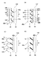
図2A及び図2Bの(A)〜(D)は、本実施の形態において製造の対象となる太陽電池複合型表示体の縦断面概略図である。本実施の形態に係る製造システム1は、太陽電池複合型表示体10A〜10Hのタイプを選択し、選択された表示体を製造することが可能となっている。以下、各太陽電池複合型表示体10A〜10Hについて説明する。
Solar cell composite display body FIGS. 2A and 2B (A) ~ (D) is a longitudinal sectional schematic view of a solar cell composite display body to be manufactured in the subject in this embodiment. The manufacturing system 1 according to the present embodiment is capable of selecting the type of the solar cell
概略として、図2A及び図2Bに示される各太陽電池複合型表示体10A〜10Hは、第1面40a及び第1面40aに対向する第2面40bを有するシート状の表示部本体40と、表示部本体40の第2面40bに対向して配置される太陽電池パネル50と、を備えている。表示部本体40には、各々が表示部本体40のシート面に対して傾斜した複数の表示面12が一軸方向に沿って配列されている。表示面12には、観察者に視認させるための表示対象が表示される。表示対象としては、図形、パターン、デザイン、色彩、絵、写真、キャラクターなどの絵柄(イメージ)や、文字、マーク、数字などの情報を例示することができる。表示対象は、静止していても動いていてもよい。また、この例では、太陽電池パネル50が矩形状であり、表示部本体40のシート面に沿って延び拡がっている。
2A and 2B, each of the composite solar cell displays 10A to 10H has a
表示部本体40の第1面40aは、太陽電池複合型表示体へ入射する太陽光等の外光等の入射面をなす。また、第1面40aは、表示対象を可視化する表示面12からの光が太陽電池複合型表示体から出射する出射面をなす。一方、第2面40bは、太陽電池パネル50の受光面50aへ向かう光が表示部本体40から出射する出射面をなす。
The
表示部本体40は、入射する光または表示部本体40から出射する光に屈折や反射などの光学的機能を発現し、当該光の進行方向を調整することが可能となっている。各太陽電池複合型表示体10A〜10Hの表示部本体40は、或る角度範囲である第1角度範囲AR1から太陽電池複合型表示体10A〜10Hに入射する光が表示面12に到達し、第1角度範囲AR1とは異なる第2角度範囲AR2から太陽電池複合型表示体10に入射する光が、太陽電池パネル50に到達するように構成される。
The display unit
このような太陽電池複合型表示体10A〜10Hによれば、表示部本体40を利用して、表対対象が視認される方向から太陽電池パネル50の受光面が視認され難くすることができる。より具体的には、第1角度範囲AR1及び第2角度範囲AR2を調整することにより、表対対象が視認される第1角度範囲AR1から、太陽電池パネル50の受光面50aが視認され難くすることができる。すなわち、第1角度範囲AR1内の方向からの表示対象の視認性を改善することができるとともに、受光面50aが観察されることによる意匠性の劣化および周囲環境との不調和を解消することが可能となる。
According to such solar cell composite
このような太陽電池複合型表示体10A〜10Hは、様々な用途で利用することができる。例えば、屋外看板、道路情報掲示板、建築物の外壁面などで用いられる数m〜数十mサイズの大型パネル用途や、ポスター、標識、建築物の内壁面などで用いられる数十cm〜数mサイズの中型パネル用途や、卓上スタンド、携帯端末などで用いられる数cm〜数十cmの小型パネル用途などを例示することができる。
Such solar cell
以下、各太陽電池複合型表示体10A〜10Hについて詳述する。図2A及び図2Bの(A)〜(D)に示される太陽電池複合型表示体10A〜10Hでは、表示部本体40の形状が互いに異なっている。なお、 図2A及び図2Bの(A)〜(D)において、互いに対応する構成に対して同一の符号を付し、重複する説明を極力省略する。
Hereinafter, each of the solar cell
(太陽電池複合表示体10A)
図2A(A)に示される太陽電池複合型表示体10Aでは、表示部本体40の第1面40aに、第1軸方向d1に配列された多数の単位レンズ30Aが設けられている。各単位レンズ30Aは、第2面40b側とは反対側に向けて凸状となるレンズ面31Aを形成している。多数の単位レンズ30Aは、そのレンズ面31Aの光軸が互いに平行となるようにして、並べられている。第1軸方向d1は、表示部本体40のシート面に沿っており、表示部本体40の法線方向に直交している。太陽電池複合型表示体10Aは、第1軸方向d1が鉛直方向と平行になる状態に配置されて使用されることが想定されている。
(Solar cell
2A (A), a large number of
単位レンズ30Aは、図3に示すように、いわゆるレンチキュラーレンズ乃至シリンドリカルレンズを構成している。すなわち、各単位レンズ30Aは、その配列方向である第1軸方向d1に対して交差する方向に線状に延びている。とりわけ図示された例において、単位レンズ30Aは、第1軸方向d1及び法線方向の両方と直交する第2軸方向d2に、直線状に延びている。また、単位レンズ30Aは、互いに同一に構成されている。そして、太陽電池複合型表示体10Aでは、表示面12が、各単位レンズ30Aのレンズ面31Aに設けられている。
As shown in FIG. 3, the
この太陽電池複合型表示体10Aでは、レンズ面31Aに設けられる表示面12の長さ寸法によって、表示面12が視認可能となる第1角度範囲AR1が決まる。また、レンズ面31Aにおける表示面12が設けられない範囲によって太陽光の透過量及び発電量が決まる。なお、この表示体10Aでは、表示面12が、曲線状をなして表示部本体40のシート面に対して傾くようになっている。
In the solar cell composite
(太陽電池複合表示体10B)
図2A(B)に示される太陽電池複合型表示体10Bでは、表示部本体40の第1面40aに、第1軸方向d1に配列された多数の単位レンズ30Bが設けられている。各単位レンズ30Bは、第2面40b側に向けて凹状となるレンズ面31Bを形成している。多数の単位レンズ30Bは、そのレンズ面31Bの光軸が互いに平行となるようにして、並べられている。太陽電池複合型表示体10Bは、第1軸方向d1が鉛直方向と平行になる状態に配置されて使用されることが想定されている。
(Solar cell
In the solar cell
単位レンズ30Bは、太陽電池複合型表示体10Aと同様に、その配列方向である第1軸方向d1に対して交差する方向に線状に延びている。とりわけ図示された例において、単位レンズ30Bは、第1軸方向d1及び法線方向の両方と直交する第2軸方向d2に、直線状に延びている。また、単位レンズ30Bは、互いに同一に構成されている。そして、太陽電池複合型表示体10Bでは、表示面12が、各単位レンズ30Bのレンズ面31Bに設けられている。
The
この太陽電池複合型表示体10Bでは、レンズ面31Bに設けられる表示面12の長さ寸法によって、表示面12が視認可能となる第1角度範囲AR1が決まる。また、レンズ面31Bにおける表示面12が設けられない範囲によって太陽光の透過量及び発電量が決まる。なお、この表示体10Bでは、表示面12が、曲線状をなして表示部本体40のシート面に対して傾くようになっている。
In the solar cell
(太陽電池複合表示体10C)
図2A(C)に示される太陽電池複合型表示体10Cでは、表示部本体40の第1面40aが、第1軸方向d1に交互に配列された複数の向き調整面30C1及び複数の集光面30C2と、を含んでいる。太陽電池複合型表示体10Cは、第1軸方向d1が鉛直方向と平行になる状態に配置されて使用されることが想定されている。このような配置の際、向き調整面30C1は、上側の端部が下側の端部よりも太陽電池パネル50から離間するように延び、集光面30C2は、上側の端部が下側の端部よりも太陽電池パネル50に接近するように延びる。
(Solar cell
2A (C), the
向き調整面30C1及び集光面30C2は、太陽電池複合型表示体10Aと同様に、その配列方向である第1軸方向d1に対して交差する方向に線状に延びている。とりわけ図示された例において、向き調整面30C1及び集光面30C2は、第1軸方向d1及び法線方向の両方と直交する第2軸方向d2に、直線状に延びている。また、向き調整面30C1及び集光面30C2は、それぞれ、互いに同一に構成されている。そして、太陽電池複合型表示体10Cでは、表示面12が、向き調整面30C1に設けられている。なお、表示面12は、少なくとも向き調整面30C1に設けられるが集光面30C2に設けられてもよい。
The direction adjusting surface 30C1 and the condensing surface 30C2 extend linearly in a direction intersecting with the first axial direction d1, which is the arrangement direction, similarly to the solar cell composite
この太陽電池複合型表示体10Cでは、向き調整面30C1及び集光面30C2に設けられる表示面12の長さ寸法によって、表示面12が視認可能となる第1角度範囲AR1が決まる。また、向き調整面30C1及び集光面30C2における表示面12が設けられない範囲によって太陽光の透過量及び発電量が決まる。
In the solar cell composite
(太陽電池複合表示体10D)
図2A(D)に示される太陽電池複合型表示体10Dでは、表示部本体40の第2面40bに、第1軸方向d1に配列された多数の単位レンズ30Dが設けられている。各単位レンズ30Dは、第1面40a側とは反対側に向けて凸状となるレンズ面31Dを形成している。多数の単位レンズ30Dは、そのレンズ面31Dの光軸が互いに平行となるようにして、並べられている。太陽電池複合型表示体10Dは、第1軸方向d1が鉛直方向と平行になる状態に配置されて使用されることが想定されている。
(Solar cell
In the solar cell
単位レンズ30Dは、太陽電池複合型表示体10Aと同様に、いわゆるレンチキュラーレンズ乃至シリンドリカルレンズを構成している。すなわち、各単位レンズ30Dは、その配列方向である第1軸方向d1に対して交差する方向に線状に延びている。とりわけ図示された例において、単位レンズ30Dは、第1軸方向d1及び法線方向の両方と直交する第2軸方向d2に、直線状に延びている。また、単位レンズ30Dは、互いに同一に構成されている。そして、太陽電池複合型表示体10Dでは、表示面12が、各単位レンズ30Dのレンズ面31Dに設けられている。
The
この太陽電池複合型表示体10Dでは、レンズ面31Dに設けられる表示面12の長さ寸法によって、表示面12が視認可能となる第1角度範囲AR1が決まる。また、レンズ面31Dにおける表示面12が設けられない範囲によって太陽光の透過量及び発電量が決まる。なお、この表示体10Dでは、表示面12が、曲線状をなして表示部本体40のシート面に対して傾くようになっている。
In the solar
(太陽電池複合表示体10E)
図2B(A)に示される太陽電池複合型表示体10Eでは、表示部本体40の第2面40bに、第1軸方向d1に配列された多数の単位レンズ30Eが設けられている。各単位レンズ30Eは、第1面40a側に向けて凹状となるレンズ面31Eを形成している。多数の単位レンズ30Eは、そのレンズ面31Eの光軸が互いに平行となるようにして、並べられている。太陽電池複合型表示体10Eは、第1軸方向d1が鉛直方向と平行になる状態に配置されて使用されることが想定されている。
(Solar cell
In the solar cell
単位レンズ30Eは、太陽電池複合型表示体10Aと同様に、その配列方向である第1軸方向d1に対して交差する方向に線状に延びている。とりわけ図示された例において、単位レンズ30Eは、第1軸方向d1及び法線方向の両方と直交する第2軸方向d2に、直線状に延びている。また、単位レンズ30Eは、互いに同一に構成されている。そして、太陽電池複合型表示体10Eでは、表示面12が、各単位レンズ30Eのレンズ面31Eに設けられている。
The
この太陽電池複合型表示体10Eでは、レンズ面31Eに設けられる表示面12の長さ寸法によって、表示面12が視認可能となる第1角度範囲AR1が決まる。また、レンズ面31Eにおける表示面12が設けられない範囲によって太陽光の透過量及び発電量が決まる。なお、この表示体10Eでは、表示面12が、曲線状をなして表示部本体40のシート面に対して傾くようになっている。
In the solar cell
(太陽電池複合表示体10F)
図2B(B)に示される太陽電池複合型表示体10Fでは、表示部本体40の第2面40bが、第1軸方向d1に交互に配列された複数の向き調整面30F1及び複数の集光面30F2と、を含んでいる。太陽電池複合型表示体10Fは、第1軸方向d1が鉛直方向と平行になる状態に配置されて使用されることが想定されている。このような配置の際、向き調整面30F1は、上側の端部が下側の端部よりも太陽電池パネル50から離間するように延び、集光面30F2は、上側の端部が下側の端部よりも太陽電池パネル50に接近するように延びる。
(Solar cell
In the solar cell
向き調整面30F1及び集光面30F2は、太陽電池複合型表示体10Aと同様に、その配列方向である第1軸方向d1に対して交差する方向に線状に延びている。とりわけ図示された例において、向き調整面30F1及び集光面30F2は、第1軸方向d1及び法線方向の両方と直交する第2軸方向d2に、直線状に延びている。また、向き調整面30F1及び集光面30F2は、それぞれ、互いに同一に構成されている。そして、太陽電池複合型表示体10Fでは、表示面12が、向き調整面30F1に設けられている。なお、表示面12は、少なくとも向き調整面30F1に設けられるが集光面30F2に設けられてもよい。
The direction adjusting surface 30F1 and the condensing surface 30F2 extend linearly in a direction intersecting with the first axial direction d1, which is the arrangement direction, similarly to the solar cell
この太陽電池複合型表示体10Fでは、向き調整面30F1及び集光面30F2に設けられる表示面12の長さ寸法によって、表示面12が視認可能となる第1角度範囲AR1が決まる。また、向き調整面30F1及び集光面30F2における表示面12が設けられない範囲によって太陽光の透過量及び発電量が決まる。
In the solar cell combined
(太陽電池複合表示体10G)
図2B(C)に示される太陽電池複合型表示体10Gでは、表示部本体40の形状が、図2A(A)の太陽電池複合型表示体10Aの表示部本体40と同様であるが、表示面12が表示部本体40の内部に設けられる点で、太陽電池複合型表示体10Aとは異なっている。太陽電池複合型表示体10Gは、第1軸方向d1が鉛直方向と平行になる状態に配置されて使用されることが想定されている。このような配置の際、表示部本体40の内部に設けられた表示面12は、上側の端部が下側の端部よりも太陽電池パネル50から離間するように延びる。また、表示面12は、例えば、第2面40bに形成される切欠の内部に設けられる。
(Solar cell
In the solar cell
この太陽電池複合型表示体10Gでは、表示面12の角度及び長さによって、表示面12が視認可能となる第1角度範囲AR1が決定される。また、表示面12の角度及び長さによって太陽光の透過量及び発電量が決まる。
In the solar cell combined
(太陽電池複合表示体10H)
図2B(D)に示される太陽電池複合型表示体10Hでは、表示部本体40が平板状に形成され、表示面12が表示部本体40の内部に設けられている。太陽電池複合型表示体10Hは、第1軸方向d1が鉛直方向と平行になる状態に配置されて使用されることが想定されている。このような配置の際、表示部本体40の内部に設けられた表示面12は、上側の端部が下側の端部よりも太陽電池パネル50から離間するように延びる。また、表示面12は、例えば、第2面40bに形成される切欠の内部に設けられる。
(Solar cell
2B (D), the display unit
この太陽電池複合型表示体10Hでは、表示面12の角度及び長さによって、表示面12が視認可能となる第1角度範囲AR1が決定される。また、表示面12の角度及び長さによって太陽光の透過量及び発電量が決まる。
In the solar cell combined
設計装置
本実施の形態に係る製造システム1では、上述の太陽電池複合型表示体10A〜10Hのタイプを選択し、選択された表示体を製造することが可能となっている。この選択は、作業者が入力部3を介して所望のタイプを設計装置2に入力することによって行われる。以下に、設計装置2の詳細を説明する。
Design Device In the manufacturing system 1 according to the present embodiment, it is possible to select the type of the above-described solar cell
図4に示すように、本実施の形態に係る設計装置2は、入射角度範囲取得部201と、発電量取得部202と、指定視野角取得部203と、表示面条件決定部204と、設定可能視野角演算部205と、設置領域決定部206と、面積演算部207と、出力部208と、を有している。設計装置2は、コンピュータであり、CPU、ROM、RAM等を含んで構成され、上述の各機能部202〜208は、CPU、ROM、RAM等によって実現される。
As shown in FIG. 4, the
この設計装置2において、入射角度範囲取得部201は、太陽電池複合型表示体に入射される光の入射角度範囲を取得するようになっている。入射角度範囲は、作業者が入力部3を介して任意に指定可能である。発電量指定部202は、指定される太陽電池複合型表示体の全体の発電量を取得する。太陽電池複合型表示体の全体の発電量とは、太陽電池複合型表示体の完成後に所望される発電量であり、作業者が入力部3を介して任意に指定可能である。
In the
また、指定視野角取得部203は、指定される太陽電池複合型表示体の表示面が視認可能となる視野角範囲(指定視野角範囲)を取得するものである。本実施の形態において、指定視野角範囲は、例えば設定可能視野角演算部205が演算する後述の設定可能視野角範囲内から作業者が入力部3を介して任意に指定可能となっている。
Further, the designated viewing
表示面条件決定部204は、入射角度範囲取得部201で取得された入射角度範囲に基づき、表示部本体40において表示面12の設置が許容されない範囲(表示面設置不可範囲)及び/又は、表示部本体40において表示面12の設置が許容される範囲(表示面設置可能範囲)を、所定の基準で決定するものである。
Based on the incident angle range acquired by the incident angle
具体的に、本実施の形態の表示面条件決定部204は、入射角度範囲取得部201で取得された入射角度範囲で入射される光が、表示面12が設けられると太陽電池パネル50に到達しなくなる表示部本体40における表示面12の設置範囲である表示面設置不可範囲を決定すると共に、入射角度範囲取得部201で取得された入射角度範囲で入射される光が、表示面12が設けられても太陽電池パネル50に到達する表示部本体40における表示面12の設置範囲である表示面設置可能範囲を決定するようになっている。
Specifically, the display surface
また、設定可能視野角演算部205は、表示面条件決定部204で決定された表示面設置不可範囲を除く範囲又は表示面設置可能範囲に表示面12を設けた場合に設定可能な表示面12が視認可能となる最大の視野角範囲である設定可能視野角範囲を演算するものである。本実施の形態において、この設定可能視野角範囲は表示部3に表示される。この際、作業者は、表示部3に表示された設定可能視野角範囲内から所望する指定視野角範囲を任意に指定し、これにより、指定視野角取得部203が指定視野角範囲を取得することになる。
The settable viewing
また、設置領域決定部206は、設定可能視野角演算部で演算された前記設定可能視野角範囲内において指定される指定視野角範囲を取得し、指定視野角範囲に対応する表示部本体40における表示面12の設置領域を決定するものである。これにより、表示部本体40の基本的な構成が定まることになる。そして、面積演算部207は、設置領域決定部206で決定された表示面12の設置領域に表示面12が設置された場合に、発電量指定部202で指定された発電量を確保できる太陽電池パネル50の面積を演算する。これにより、太陽電池パネル50の大きさも定まることになる。
In addition, the installation
そして、出力部208は、設置領域決定部206で決定された表示面12の設置領域及び面積演算部207で決定された面積の情報から、設計データを生成し、製造装置5に出力する。これにより、製造装置5は、設計データに基づく表示部本体40を製造することが可能となる。すなわち、本実施の形態では、製造装置5が3Dプリンタであるため、製造装置5は設計データに基づき、表示部本体40を製造する。なお、製造装置5が、金型製造装置及び当該金型製造装置で製造された金型で成型を行う成型装置とからなるユニットである場合には、まず金型製造装置が設計データに基づき表示部本体40のための金型を作製し、その後、成型装置が作製された金型により表示部本体40の成型を行うことになる。
Then, the
製造方法
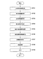
次に、製造システム1による太陽電池複合型表示体の表示部本体40の製造方法について、図5に示すフローチャート及び図6に示す製造方法の工程の流れを説明する図を参照しつつ説明する。
Manufacturing Method Next, a manufacturing method of the display unit
まず、ステップS501において、入射角度範囲取得部201が、太陽電池複合型表示体に入射される光の入射角度範囲を取得する。ここで、入射角度範囲は、任意に指定可能であるが、典型的には、設置が想定される季節や地域において太陽光が太陽電池複合型表示体に入射される入射角度を含む範囲として指定されることが想定されている。
First, in step S501, the incident angle
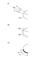
以下の表1は、世界の幾つかの国の主要な都市における季節ごとの南中高度(°)を示している。例えば、製造対象の太陽電池複合型表示体がある国の春分秋分を含む期間に使用されることが想定されている場合には、入射角度範囲は、使用が想定される国の主要な都市における春分秋分の南中高度を含む範囲として指定されてもよい。例えば、使用されることが想定される国が日本の場合は、54°から56°までの高度が少なくとも含まれる範囲を、入射角度範囲としてもよい。さらに、世界の多くの国で使用されることが想定されている場合には、入射角度範囲は、49°から61°までの高度が含まれる範囲として指定されてもよい。また、日本で一年を通して使用されることが想定されている場合には、入射角度範囲は、31°から79°までの高度が含まれる範囲として指定されてもよい。ここで、図6(A)は、図2A(A)に示した太陽電池複合型表示体10Aが製造の対象である場合に、入射角度範囲W1を指定した様子を示している。
Table 1 below shows the seasonal south-central elevation (°) in major cities in some countries of the world. For example, if it is assumed that the solar cell composite display to be manufactured is used during a period including the spring equinox of a certain country, the incident angle range is set in a main city of the country where the use is assumed. It may be specified as a range including the south-central altitude of the equinox. For example, when the country assumed to be used is Japan, a range including at least the altitude from 54 ° to 56 ° may be set as the incident angle range. Further, if intended for use in many countries of the world, the angle of incidence range may be specified as a range that includes altitudes from 49 ° to 61 °. Further, when it is assumed to be used throughout the year in Japan, the incident angle range may be specified as a range including an altitude from 31 ° to 79 °. Here, FIG. 6A shows a state in which the incident angle range W1 is specified when the solar cell combined

次いで、ステップS502においては、発電量取得部202が、指定される太陽電池パネル50の全体の発電量を取得する。なお、太陽電池パネル50の全体の発電量の指定及び取得は、ステップS501の直後でなくてもよく、例えば、後述のステップS506における設置領域決定の処理の後でもよい。
Next, in step S502, the power generation
次いで、ステップS503において、表示面条件決定部204が、入射角度範囲取得部201で取得された入射角度範囲で入射される光が、表示面12が設けられると太陽電池パネル50に到達しなくなる表示面設置不可範囲、及び/又は、入射角度範囲取得部201で取得された入射角度範囲で入射される光が、表示面12が設けられても太陽電池パネル50に到達する表示面設置可能範囲を決定する。
Next, in step S <b> 503, the display surface
本実施の形態において、表示面設置不可範囲は、入射角度範囲取得部201で取得された入射角度範囲で入射される全ての光が、表示面12が設けられない場合には、表示部本体40を通過して太陽電池パネル50に至る表示部本体40における範囲を意味する。一方、表示面設置可能範囲は、表示面設置不可範囲を除く範囲を意味する。
In the present embodiment, the display surface non-installable range is the display unit
図6(B)を参照し、太陽電池複合型表示体10Aが製造の対象であり、入射角度範囲W1が指定された場合には、例えば、図中のW2に示すレンズ面31Aにおける範囲が、表示面設置不可範囲となり、レンズ面31Aにおける表示面設置不可範囲W2を除く範囲が、表示面設置可能範囲となる。
Referring to FIG. 6 (B), when solar cell
次いで、ステップS504において、設定可能視野角演算部205が、表示面条件決定部204で決定された表示面設置不可範囲W2を除く範囲(W3)又は表示面設置可能範囲W3に表示面12を設けた場合に設定可能な表示面12が視認可能となる最大の視野角範囲である設定可能視野角範囲を演算する。ここで、本実施の形態では、設計装置2が、設定可能視野角範囲を表示部4に出力し、表示部4に設定可能視野角範囲を表示する。そして、作業者が入力部3を用いて、設定可能視野角範囲内において指定視野角範囲を指定することが可能となる。
Next, in step S504, the settable viewing
次いで、作業者から指定視野角範囲が指定されると、ステップS505において、指定視野角取得部203が、指定視野角範囲を取得し、設置領域決定部206に出力する。次いで、ステップS506において、設置領域決定部206が、指定視野角範囲を取得し、指定視野角範囲に対応する表示部本体40における表示面12の設置領域を決定する。ここで、図6(C)は、指定視野角範囲に対応する表示面12の設置領域T1に表示面12が設置された様子を示している。
Next, when the designated viewing angle range is designated by the operator, the designated viewing
その後、ステップS507においては、面積演算部207が、設置領域決定部206で決定された表示面12の設置領域に表示面12が設置された場合に、発電量取得部202で取得された発電量を確保できる太陽電池パネル50の面積を演算する。
Then, in step S507, when the
その後、ステップS508において、出力部208が、設置領域決定部206で決定された表示面12の設置領域及び面積演算部207で決定された面積の情報から、設計データを生成し、製造装置5に出力する。これにより、製造装置5は、設置領域決定部206で決定された表示面12の設置領域に表示面12が設けられ、且つ面積演算部207で演算された面積となる太陽電池パネル50を全体的に覆う寸法の表示部本体40を製造することが可能となる。
After that, in step S508, the
以上に説明した本実施の形態によれば、所望の発電性能及び表示性能を充足する太陽電池複合型表示体を簡易に製造することができる。すなわち、本実施の形態によれば、季節や設置地域等によって変動する太陽光の入射条件に応じて好適な発電を行いつつ所望される表示部分(表示面12)の視認性を充足する最適な形状の選定を容易に行うことが可能となり、もって所望の発電性能及び表示性能を充足する太陽電池複合型表示体10の表示部本体40を簡易に製造することができる。
According to the present embodiment described above, a solar cell combined display that satisfies desired power generation performance and display performance can be easily manufactured. In other words, according to the present embodiment, an optimal power generation that satisfies the visibility of a desired display portion (display surface 12) while performing suitable power generation in accordance with the incident conditions of sunlight that fluctuates depending on the season, the installation area, and the like. The shape can be easily selected, and the display unit
<第2の実施の形態>
次に、本発明の第2の実施の形態について説明する。本実施の形態において、製造システム1の構成は、第1の実施の形態と同様のため、説明を省略する。ただし、本実施の形態では、設計装置2における発電量取得部202が、指定される太陽電池パネル50の全体の発電量に加え、指定される太陽電池パネル50の所定面積当たりの発電量(単位発電量)を取得する機能を有している。
<Second embodiment>
Next, a second embodiment of the present invention will be described. In the present embodiment, the configuration of the manufacturing system 1 is the same as that of the first embodiment, and the description is omitted. However, in the present embodiment, the power generation
上述の単位発電量とは、太陽電池パネル50の所定面積当たりの発電量の程度(発電レベル)を示すものである。第1の実施の形態では、太陽光の入射角度範囲に応じて、表示面設置不可範囲が決定されたが、この表示面設置不可範囲は、入射角度範囲内の角度で入射される太陽光の全てを太陽電池パネル50に到達させ、適正な使用を確保する指標である。一方で、太陽光には、様々な角度範囲で進行する散乱光等も含まれており、表示面設置不可範囲よりも広い範囲から太陽光を取り込んだ場合には、表示面設置不可範囲のみから取り込む場合に比較して、発電量が増加する傾向がある。一方で、この場合、表示面12の設置範囲は制約される。太陽電池複合型表示体の製造では、所望の発電量を優先的に確保しつつ、発電量の確保によって制約された条件下で表示面12の視認性を好適に確保する設計を行う場合がある。本実施の形態では、このような設計を効率的に行うことが可能となる。
The above-mentioned unit power generation indicates the degree of power generation per predetermined area of the solar cell panel 50 (power generation level). In the first embodiment, the display surface non-installable range is determined according to the incident angle range of the sunlight. However, the display surface non-installable range is determined by the sunlight incident at an angle within the incident angle range. It is an index that allows everything to reach the
図7は、本実施の形態に係る製造方法を示すフローチャートであり、図8は、本実施の形態に係る製造方法の工程の流れを説明する図である。 FIG. 7 is a flowchart illustrating the manufacturing method according to the present embodiment, and FIG. 8 is a diagram illustrating the flow of steps of the manufacturing method according to the present embodiment.
本実施の形態では、図7に示すように、まず、ステップS701において、入射角度範囲取得部201が、太陽電池複合型表示体に入射される光の入射角度範囲を取得する。図8(A)は、図2A(A)に示した太陽電池複合型表示体10Aが製造の対象である場合に、入射角度範囲W7を指定した様子を示している。
In the present embodiment, as shown in FIG. 7, first, in step S701, the incident angle
入射角度範囲W7が指定された場合、入射角度範囲内の角度で入射される太陽光の全てを太陽電池パネル50に到達させる範囲W8(表示面設置不可範囲に相当)が定まる。この範囲W8のみに太陽光が通過した場合には、太陽電池パネル50の所定面積当たりの単位発電量を算出可能である。また、範囲W8よりも広い範囲に、入射角度範囲内の角度で入射される太陽光が通過する場合(例えば、範囲W9、W10)の所定面積当たりの単位発電量も算出可能である。
When the incident angle range W7 is specified, a range W8 (corresponding to a display surface non-installable range) in which all of the sunlight incident at an angle within the incident angle range reaches the
本実施の形態は、上述のように入射角度範囲が決定されることで定まる複数の単位発電量を、作業者が選択可能となるように構成されている。そして、ステップS702においては、発電量取得部202が、作業者より指定される単位発電量を取得する。
The present embodiment is configured so that the operator can select a plurality of unit power generation amounts determined by determining the incident angle range as described above. Then, in step S702, the power generation
次いで、ステップS703においては、発電量取得部202が、指定される太陽電池パネル50の全体の発電量を取得する。なお、太陽電池パネル50の全体の発電量の指定及び取得は、ステップS702の直後でなくてもよく、例えば、後述のステップS707における設置領域決定の処理の後でもよい。
Next, in step S703, the power generation
次いで、ステップS704において、本実施の形態では、表示面条件決定部204が、入射角度範囲取得部201で取得された入射角度範囲W7で光が入射される際、表示面12が設けられると指定された単位発電量が得られなくなる表示部本体40における表示面の設置範囲である表示面設置不可範囲を決定すると共に、入射角度範囲取得部201で取得された入射角度範囲W7で光が入射される際、表示面12が設けられても指定された単位発電量が得られる表示部本体40における表示面12の設置範囲である表示面設置可能範囲を決定する。
Next, in step S704, in the present embodiment, the display surface
具体的に、図8(B)には、図8(A)に示した範囲W9に対応する単位発電量が指定された場合の表示面設置不可範囲W19と、範囲W10に対応する単位発電量が指定された場合の表示面設置不可範囲W20とが示されている。範囲W9に対応する単位発電量が指定された場合の表示面設置可能範囲は、W29で示す範囲となり、範囲W10に対応する単位発電量が指定された場合の表示面設置可能範囲は、W30で示す範囲となる。 Specifically, FIG. 8B shows a display surface non-installable range W19 when the unit power generation corresponding to the range W9 shown in FIG. 8A is designated, and a unit power generation corresponding to the range W10. The display surface non-installable range W20 when is designated is shown. The display surface installable range when the unit power generation corresponding to the range W9 is specified is the range indicated by W29, and the display surface installable range when the unit power generation corresponding to the range W10 is specified is W30. It becomes the range shown.
次いで、ステップS705において、設定可能視野角演算部205が、表示面条件決定部204で決定された表示面設置不可範囲を除く範囲又は表示面設置可能範囲に表示面12を設けた場合に設定可能な表示面12が視認可能となる最大の視野角範囲である設定可能視野角範囲を演算する。ここで、本実施の形態では、設計装置2が、設定可能視野角範囲を表示部4に出力し、表示部4に設定可能視野角範囲を表示する。そして、作業者が入力部3を用いて、設定可能視野角範囲内において指定視野角範囲を指定することが可能となる。
Next, in step S705, the settable viewing
次いで、作業者から指定視野角範囲が指定されると、ステップS706において、指定視野角取得部203が、指定視野角範囲を取得し、設置領域決定部206に出力する。次いで、ステップS707において、設置領域決定部206が、指定視野角範囲を取得し、指定視野角範囲に対応する表示部本体40における表示面12の設置領域を決定する。ここで、図8(C)は、指定視野角範囲に対応する表示面12の設置領域T2に表示面12が設置された様子を示している。
Next, when the designated viewing angle range is designated by the operator, in step S706, the designated viewing
その後、ステップS708において、面積演算部207が、設置領域決定部206で決定された表示面12の設置領域に表示面12が設置された場合に、発電量取得部202で取得された発電量を確保できる太陽電池パネル50の面積を演算する。
Thereafter, in step S708, when the
その後、ステップS709において、出力部208が、設置領域決定部206で決定された表示面12の設置領域及び面積演算部207で決定された面積の情報から、設計データを生成し、製造装置5に出力する。これにより、製造装置5は、設置領域決定部206で決定された表示面12の設置領域に表示面12が設けられ、且つ面積演算部207で演算された面積となる太陽電池パネル50を全体的に覆う寸法の表示部本体40を製造することが可能となる。
Then, in step S709, the
上述した第2の実施の形態においても、第1の実施の形態と同様の効果が得られる。 In the above-described second embodiment, the same effects as in the first embodiment can be obtained.
<他の実施の形態>
本発明の他の実施の形態について説明する。
他の実施の形態として、上述した第1の実施の形態又は第2の実施の形態において、入射角度範囲取得部201(ステップS501)を備えない以外は同様のものが挙げられる。本実施の形態では、主として、入力部3により指定された全体の発電量及び/又は単位発電量に基づいて、表示面条件を決定することによって、所望の発電性能を確保することができる。また、指定された全体の発電量及び/又は単位発電量の確保する入射角度範囲の知見を持たない作業者であっても表示部本体40を製造できる。この場合、設計装置2は、表示面条件に対応させた全体の発電量及び/又は単位発電量の演算データを保有することが好ましく、指定された全体の発電量及び/又は単位発電量と演算データを照合することによって表示面条件を決定することができる。
<Other embodiments>
Another embodiment of the present invention will be described.
As another embodiment, the same as the above-described first or second embodiment except that the incident angle range acquisition unit 201 (step S501) is not provided. In the present embodiment, a desired power generation performance can be ensured mainly by determining display surface conditions based on the entire power generation amount and / or unit power generation amount specified by the input unit 3. In addition, even if the worker does not have knowledge of the incident angle range that secures the specified whole power generation amount and / or unit power generation amount, the display unit
さらに他の実施の形態として、上述した第1の実施の形態において、入射角度範囲取得部201(ステップS501)、発電量取得部202(ステップS502)、表示面条件決定部204(ステップS503)、設定可能視野角演算部205(ステップS504)、及び面積演算部207(ステップS507)を備えない以外は同様のものが挙げられる。本実施の形態では、主として、入力部3により指定された指定視野角範囲を指定視野角取得部203で取得した後、その指定視野角範囲に基づいて、表示面12の設定領域を設定領域決定部206で決定することによって、所望の表示性能を確保することができる。
As still another embodiment, in the first embodiment described above, the incident angle range acquisition unit 201 (step S501), the power generation amount acquisition unit 202 (step S502), the display surface condition determination unit 204 (step S503), The same configuration is provided except that the settable viewing angle calculation unit 205 (step S504) and the area calculation unit 207 (step S507) are not provided. In the present embodiment, mainly after the designated viewing angle range specified by the input unit 3 is acquired by the designated viewing
以上、本発明の各実施の形態を説明したが、本発明は上述の実施の形態に限定されるものではない。なお、本実施の形態では、設計装置2の各機能がソフトウェアで構成される。ソフトウェアで構成する場合には、設計装置2の機能を実現するプログラムをフレキシブルディスクやCD−ROM等の記録媒体に収納し、コンピュータに読み込ませて実行させてもよい。記録媒体は、磁気ディスクや光ディスク等の着脱可能なものに限定されず、ハードディスク装置やメモリなどの固定型の記録媒体でもよい。
The embodiments of the present invention have been described above, but the present invention is not limited to the above embodiments. In the present embodiment, each function of the
1 製造システム、2 設計装置、3 入力部、4 表示部、5 製造装置、10A〜10H 太陽電池複合型表示体、12 表示面、40 表示部本体、40a 第1面、40b 第2面、50 太陽電池パネル、201 入射角度範囲取得部、202 発電量取得部、203 指定視野角取得部、204 表示面条件決定部、205 設定可能視野角演算部、206 設置領域決定部、207 面積演算部。 DESCRIPTION OF SYMBOLS 1 Manufacturing system, 2 design apparatus, 3 input part, 4 display parts, 5 manufacturing apparatus, 10A-10H solar cell composite type display body, 12 display surfaces, 40 display part main body, 40a 1st surface, 40b 2nd surface, 50 Solar cell panel, 201 incident angle range acquisition unit, 202 power generation amount acquisition unit, 203 designated viewing angle acquisition unit, 204 display surface condition determination unit, 205 settable viewing angle calculation unit, 206 installation area determination unit, 207 area calculation unit.
Claims (11)
前記太陽電池複合型表示体に入射される光の入射角度範囲を取得する入射角度範囲取得部と、
前記入射角度範囲取得部で取得された入射角度範囲で入射される光が、前記表示面が設けられると前記太陽電池パネルに到達しなくなる前記表示部本体における前記表示面の設置範囲である表示面設置不可範囲を決定する、及び/又は、前記入射角度範囲取得部で取得された入射角度範囲で入射される光が、前記表示面が設けられても前記太陽電池パネルに到達する前記表示部本体における前記表示面の設置範囲である表示面設置可能範囲を決定する、表示面条件決定部と、
前記表示面条件決定部で決定された前記表示面設置不可範囲を除く範囲又は前記表示面設置可能範囲に前記表示面を設けた場合に設定可能な前記表示面が視認可能となる最大の視野角範囲である設定可能視野角範囲を演算する設定可能視野角演算部と、
前記設定可能視野角演算部で演算された前記設定可能視野角範囲内において指定される指定視野角範囲を取得し、前記指定視野角範囲に対応する前記表示部本体における前記表示面の設置領域を決定する設置領域決定部と、
前記設置領域決定部で決定された前記表示面の設置領域に基づき、表示部本体を製造する製造装置と、を有する、太陽電池複合型表示体の表示部本体の製造システム。 A sheet-shaped display unit main body having a first surface and a second surface opposed to the first surface, and a solar cell panel arranged to face the second surface of the display unit main body; A display unit main body, a display unit main body manufacturing system of a solar cell composite display body in which a plurality of display surfaces each inclined with respect to a sheet surface of the display unit main body are arranged along a uniaxial direction,
An incident angle range acquisition unit that acquires an incident angle range of light incident on the solar cell composite display,
The light incident on the incident angle range acquired by the incident angle range acquiring unit, the display surface is an installation range of the display surface in the display unit main body that does not reach the solar cell panel when the display surface is provided. The display unit main body that determines a non-installable range and / or light incident in the incident angle range acquired by the incident angle range acquisition unit reaches the solar cell panel even when the display surface is provided. A display surface condition determining unit that determines a display surface installable range that is an installation range of the display surface,
The maximum viewing angle at which the display surface that can be set when the display surface is provided in the range excluding the display surface non-installable range or the display surface installable range determined by the display surface condition determination unit is visible. A settable viewing angle calculation unit that calculates a settable viewing angle range that is a range;
Obtain a specified viewing angle range specified within the settable viewing angle range calculated by the settable viewing angle calculation unit, and set the installation area of the display surface in the display unit body corresponding to the specified viewing angle range. An installation area determining unit to determine,
A manufacturing apparatus for manufacturing a display unit main body based on the installation area of the display surface determined by the installation area determining unit;
前記設置領域決定部で決定された前記表示面の設置領域に前記表示面が設置された場合に、前記発電量取得部で取得された発電量を確保できる前記太陽電池パネルの面積を演算する面積演算部と、をさらに有し、
前記製造装置は、前記設置領域決定部で決定された前記表示面の設置領域に前記表示面が設けられ、且つ前記面積演算部で演算された面積となる前記太陽電池パネルを全体的に覆う寸法の前記表示部本体を製造する、請求項1に記載の太陽電池複合型表示体の表示部本体の製造システム。 A power generation amount obtaining unit that obtains the entire power generation amount of the specified solar cell panel,
When the display surface is installed in the installation area of the display surface determined by the installation area determination unit, an area for calculating the area of the solar cell panel that can secure the power generation amount acquired by the power generation amount acquisition unit. An arithmetic unit, and
The manufacturing apparatus is configured such that the display surface is provided in the installation area of the display surface determined by the installation area determination unit, and that the entire solar cell panel has an area calculated by the area calculation unit. The system for manufacturing a display unit main body of the solar cell combined display according to claim 1, wherein the display unit main body is manufactured.
前記太陽電池複合型表示体に入射される光の入射角度範囲を取得する入射角度範囲取得部と、
指定される前記太陽電池パネルの所定面積当たりの単位発電量を取得する単位発電量取得部と、
前記入射角度範囲取得部で取得された入射角度範囲で光が入射される際、前記表示面が設けられると前記単位発電量取得部で取得された単位発電量が得られなくなる前記表示部本体における前記表示面の設置範囲である表示面設置不可範囲を決定する、及び/又は、前記入射角度範囲取得部で取得された入射角度範囲で光が入射される際、前記表示面が設けられても前記単位発電量取得部で取得された単位発電量が得られる前記表示部本体における前記表示面の設置範囲である表示面設置可能範囲を決定する、表示面条件決定部と、
前記表示面条件決定部で決定された前記表示面設置不可範囲を除く範囲又は前記表示面設置可能範囲に前記表示面を設けた場合に設定可能な前記表示面が視認可能となる最大の視野角範囲である設定可能視野角範囲を演算する設定可能視野角演算部と、
前記設定可能視野角演算部で演算された前記設定可能視野角範囲内において指定される指定視野角範囲を取得し、前記指定視野角範囲に対応する前記表示部本体における前記表示面の設置領域を決定する設置領域決定部と、
前記設置領域決定部で決定された前記表示面の設置領域に基づき、表示部本体を製造する製造装置と、を有する、太陽電池複合型表示体の表示部本体の製造システム。 A sheet-shaped display unit main body having a first surface and a second surface opposed to the first surface, and a solar cell panel arranged to face the second surface of the display unit main body; A display unit main body, a display unit main body manufacturing system of a solar cell composite display body in which a plurality of display surfaces each inclined with respect to a sheet surface of the display unit main body are arranged along a uniaxial direction,
An incident angle range acquisition unit that acquires an incident angle range of light incident on the solar cell composite display,
A unit power generation amount acquisition unit that obtains a unit power generation amount per predetermined area of the specified solar cell panel,
When light is incident on the incident angle range acquired by the incident angle range acquisition unit, the unit power generation amount acquired by the unit power generation amount acquisition unit cannot be obtained when the display surface is provided. The display surface is not provided even if the display surface is not determined, and / or the light is incident on the incident angle range acquired by the incident angle range acquisition unit. A display surface condition determining unit that determines a display surface installable range that is an installation range of the display surface in the display unit main body in which the unit power generation amount obtained by the unit power generation amount acquisition unit is obtained,
The maximum viewing angle at which the display surface that can be set when the display surface is provided in the range excluding the display surface non-installable range or the display surface installable range determined by the display surface condition determination unit is visible. A settable viewing angle calculation unit that calculates a settable viewing angle range that is a range;
Obtain a specified viewing angle range specified within the settable viewing angle range calculated by the settable viewing angle calculation unit, and set the installation area of the display surface in the display unit body corresponding to the specified viewing angle range. An installation area determining unit to determine,
A manufacturing apparatus for manufacturing a display unit main body based on the installation area of the display surface determined by the installation area determining unit;
前記設置領域決定部で決定された前記表示面の設置領域に前記表示面が設置された場合に、前記発電量取得部で取得された発電量を確保できる前記太陽電池パネルの面積を演算する面積演算部と、をさらに有し、
前記製造装置は、前記設置領域決定部で決定された前記表示面の設置領域に前記表示面が設けられ、且つ前記面積演算部で演算された面積となる前記太陽電池パネルを全体的に覆う寸法の前記表示部本体を製造する、請求項3に記載の太陽電池複合型表示体の表示部本体の製造システム。 A power generation amount obtaining unit that obtains the entire power generation amount of the specified solar cell panel,
When the display surface is installed in the installation area of the display surface determined by the installation area determination unit, an area for calculating the area of the solar cell panel that can secure the power generation amount acquired by the power generation amount acquisition unit. An arithmetic unit, and
The manufacturing apparatus is configured such that the display surface is provided in the installation area of the display surface determined by the installation area determination unit, and that the entire solar cell panel has an area calculated by the area calculation unit. The system for manufacturing a display unit main body of the solar cell composite display according to claim 3, wherein the display unit main body is manufactured.
指定される前記太陽電池パネルの全体の発電量を取得する発電量取得部、及び/又は、指定される前記太陽電池パネルの所定面積当たりの単位発電量を取得する単位発電量取得部と、
前記表示面が設けられると前記発電量取得部で取得された全体の発電量及び/又は前記単位発電量取得部で取得された単位発電量が得られなくなる前記表示部本体における前記表示面の設置範囲である表示面設置不可範囲を決定する、及び/又は、前記表示面が設けられても前記発電量取得部で取得された全体の発電量及び/又は前記単位発電量取得部で取得された単位発電量が得られる前記表示部本体における前記表示面の設置範囲である表示面設置可能範囲を決定する、表示面条件決定部と、
前記表示面条件決定部で決定された前記表示面設置不可範囲を除く範囲又は前記表示面設置可能範囲に前記表示面を設けた場合に設定可能な前記表示面が視認可能となる最大の視野角範囲である設定可能視野角範囲を演算する設定可能視野角演算部と、
前記設定可能視野角演算部で演算された前記設定可能視野角範囲内において指定される指定視野角範囲を取得し、前記指定視野角範囲に対応する前記表示部本体における前記表示面の設置領域を決定する設置領域決定部と、
前記設置領域決定部で決定された前記表示面の設置領域に基づき、表示部本体を製造する製造装置と、を有する、太陽電池複合型表示体の表示部本体の製造システム。 A sheet-shaped display unit main body having a first surface and a second surface opposed to the first surface, and a solar cell panel arranged to face the second surface of the display unit main body; A display unit main body, a display unit main body manufacturing system of a solar cell composite display body in which a plurality of display surfaces each inclined with respect to a sheet surface of the display unit main body are arranged along a uniaxial direction,
A power generation amount acquisition unit that acquires the entire power generation amount of the specified solar cell panel, and / or a unit power generation amount acquisition unit that obtains a unit power generation amount per a predetermined area of the specified solar cell panel;
Installation of the display surface in the display unit main body when the display surface is provided, the entire power generation amount obtained by the power generation amount obtaining unit and / or the unit power generation amount obtained by the unit power generation amount obtaining unit cannot be obtained. Determine the display surface installation impossible range that is the range, and / or even if the display surface is provided, the entire power generation amount acquired by the power generation amount acquisition unit and / or the unit power generation amount acquired by the unit power generation amount acquisition unit A display surface condition determining unit that determines a display surface installable range that is an installation range of the display surface in the display unit main body in which a unit power generation amount is obtained,
The maximum viewing angle at which the display surface that can be set when the display surface is provided in the range excluding the display surface non-installable range or the display surface installable range determined by the display surface condition determination unit is visible. A settable viewing angle calculation unit that calculates a settable viewing angle range that is a range;
Obtain a specified viewing angle range specified within the settable viewing angle range calculated by the settable viewing angle calculation unit, and set the installation area of the display surface in the display unit body corresponding to the specified viewing angle range. An installation area determining unit to determine,
A manufacturing apparatus for manufacturing a display unit main body based on the installation area of the display surface determined by the installation area determining unit;
前記太陽電池複合型表示体に入射される光の入射角度範囲を取得する入射角度範囲取得工程と、
前記入射角度範囲取得工程で取得された入射角度範囲で入射される光が、前記表示面が設けられると前記太陽電池パネルに到達しなくなる前記表示部本体における前記表示面の設置範囲である表示面設置不可範囲を決定する、及び/又は、前記入射角度範囲取得工程で取得された入射角度範囲で入射される光が、前記表示面が設けられても前記太陽電池パネルに到達する前記表示部本体における前記表示面の設置範囲である表示面設置可能範囲を決定する、表示面条件決定工程と、
前記表示面条件決定工程で決定された前記表示面設置不可範囲を除く範囲又は前記表示面設置可能範囲に前記表示面を設けた場合に設定可能な前記表示面が視認可能となる最大の視野角範囲である設定可能視野角範囲を演算する設定可能視野角演算工程と、
前記設定可能視野角演算工程で演算された前記設定可能視野角範囲内において指定される指定視野角範囲を取得し、前記指定視野角範囲に対応する前記表示部本体における前記表示面の設置領域を決定する設置領域決定工程と、
前記設置領域決定工程で決定された前記表示面の設置領域に基づき、表示部本体を製造する製造工程と、を有する、太陽電池複合型表示体の表示部本体の製造方法。 A sheet-shaped display unit main body having a first surface and a second surface opposed to the first surface, and a solar cell panel arranged to face the second surface of the display unit main body; A method for manufacturing a display unit main body of a solar cell composite display, in which a plurality of display surfaces each inclined with respect to a sheet surface of the display unit main body are arranged along a uniaxial direction on a display unit main body,
An incident angle range obtaining step of obtaining an incident angle range of light incident on the solar cell composite display,
Light incident on the incident angle range acquired in the incident angle range acquiring step, a display surface that is an installation range of the display surface in the display unit body that does not reach the solar cell panel when the display surface is provided. The display unit main body that determines a non-installable range and / or light that is incident within the incident angle range acquired in the incident angle range acquiring step, reaches the solar cell panel even when the display surface is provided. Determining a display surface installable range which is an installation range of the display surface, a display surface condition determining step,
The maximum viewing angle at which the display surface that can be set when the display surface is provided in the range excluding the display surface non-installable range or the display surface installable range determined in the display surface condition determination step becomes visible. A settable viewing angle calculating step of calculating a settable viewing angle range which is a range;
Obtain a specified viewing angle range specified in the settable viewing angle range calculated in the settable viewing angle calculation step, and set an installation area of the display surface in the display unit body corresponding to the specified viewing angle range. An installation area determination process to be determined;
A manufacturing step of manufacturing a display unit main body based on the installation area of the display surface determined in the installation area determining step.
前記太陽電池複合型表示体に入射される光の入射角度範囲を取得する入射角度範囲取得工程と、
指定される前記太陽電池パネルの所定面積当たりの単位発電量を取得する単位発電量取得工程と、
前記入射角度範囲取得工程で取得された入射角度範囲で光が入射される際、前記表示面が設けられると前記単位発電量取得工程で取得された単位発電量が得られなくなる前記表示部本体における前記表示面の設置範囲である表示面設置不可範囲を決定する、及び/又は、前記入射角度範囲取得工程で取得された入射角度範囲で光が入射される際、前記表示面が設けられても前記単位発電量取得工程で取得された単位発電量が得られる前記表示部本体における前記表示面の設置範囲である表示面設置可能範囲を決定する、表示面条件決定工程と、
前記表示面条件決定工程で決定された前記表示面設置不可範囲を除く範囲又は前記表示面設置可能範囲に前記表示面を設けた場合に設定可能な前記表示面が視認可能となる最大の視野角範囲である設定可能視野角範囲を演算する設定可能視野角演算工程と、
前記設定可能視野角演算工程で演算された前記設定可能視野角範囲内において指定される指定視野角範囲を取得し、前記指定視野角範囲に対応する前記表示部本体における前記表示面の設置領域を決定する設置領域決定工程と、
前記設置領域決定工程で決定された前記表示面の設置領域に基づき、表示部本体を製造する製造工程と、を有する、太陽電池複合型表示体の表示部本体の製造方法。 A sheet-shaped display unit main body having a first surface and a second surface opposed to the first surface, and a solar cell panel arranged to face the second surface of the display unit main body; A method for manufacturing a display unit main body of a solar cell composite display, in which a plurality of display surfaces each inclined with respect to a sheet surface of the display unit main body are arranged along a uniaxial direction on a display unit main body,
An incident angle range obtaining step of obtaining an incident angle range of light incident on the solar cell composite display,
A unit power generation amount obtaining step of obtaining a unit power generation amount per predetermined area of the specified solar cell panel,
When light is incident on the incident angle range obtained in the incident angle range obtaining step, the display unit main body cannot obtain the unit power generation amount obtained in the unit power generation amount obtaining step when the display surface is provided. When the display surface is not set, which is the installation range of the display surface, and / or when light is incident on the incident angle range obtained in the incident angle range obtaining step, the display surface may be provided. A display surface condition determining step of determining a display surface installable range that is an installation range of the display surface in the display unit main body in which the unit power generation amount obtained in the unit power generation amount obtaining step is obtained,
The maximum viewing angle at which the display surface that can be set when the display surface is provided in the range excluding the display surface non-installable range or the display surface installable range determined in the display surface condition determination step becomes visible. A settable viewing angle calculating step of calculating a settable viewing angle range which is a range;
Obtain a specified viewing angle range specified in the settable viewing angle range calculated in the settable viewing angle calculation step, and set an installation area of the display surface in the display unit body corresponding to the specified viewing angle range. An installation area determination process to be determined;
A manufacturing step of manufacturing a display unit main body based on the installation area of the display surface determined in the installation area determining step.
指定される前記太陽電池パネルの全体の発電量を取得する発電量取得工程、及び/又は、指定される前記太陽電池パネルの所定面積当たりの単位発電量を取得する単位発電量取得工程と、
前記表示面が設けられると前記発電量取得工程で取得された全体の発電量及び/又は前記単位発電量取得工程で取得された単位発電量が得られなくなる前記表示部本体における前記表示面の設置範囲である表示面設置不可範囲を決定する、及び/又は、前記表示面が設けられても前記発電量取得工程で取得された全体の発電量及び/又は前記単位発電量取得工程で取得された単位発電量が得られる前記表示部本体における前記表示面の設置範囲である表示面設置可能範囲を決定する、表示面条件決定工程と、
前記表示面条件決定工程で決定された前記表示面設置不可範囲を除く範囲又は前記表示面設置可能範囲に前記表示面を設けた場合に設定可能な前記表示面が視認可能となる最大の視野角範囲である設定可能視野角範囲を演算する設定可能視野角演算工程と、
前記設定可能視野角演算工程で演算された前記設定可能視野角範囲内において指定される指定視野角範囲を取得し、前記指定視野角範囲に対応する前記表示部本体における前記表示面の設置領域を決定する設置領域決定工程と、
前記設置領域決定工程で決定された前記表示面の設置領域に基づき、表示部本体を製造する製造工程と、を有する、太陽電池複合型表示体の表示部本体の製造方法。 A sheet-shaped display unit main body having a first surface and a second surface opposed to the first surface, and a solar cell panel arranged to face the second surface of the display unit main body; A method for manufacturing a display unit main body of a solar cell composite display, in which a plurality of display surfaces each inclined with respect to a sheet surface of the display unit main body are arranged along a uniaxial direction on a display unit main body,
A power generation amount obtaining step of obtaining the entire power generation amount of the specified solar cell panel, and / or a unit power generation amount obtaining step of obtaining a unit power generation amount per a predetermined area of the specified solar cell panel;
Installation of the display surface in the display unit main body when the display surface is provided, the total power generation amount obtained in the power generation amount obtaining step and / or the unit power generation amount obtained in the unit power generation amount obtaining step cannot be obtained. Determine the display surface non-installable range, which is a range, and / or obtain the entire power generation amount obtained in the power generation amount obtaining step and / or the unit power generation amount obtaining step even if the display surface is provided. A display surface condition determining step of determining a display surface installable range that is an installation range of the display surface in the display unit main body in which a unit power generation amount is obtained,
The maximum viewing angle at which the display surface that can be set when the display surface is provided in the range excluding the display surface non-installable range or the display surface installable range determined in the display surface condition determination step becomes visible. A settable viewing angle calculating step of calculating a settable viewing angle range which is a range;
Obtain a specified viewing angle range specified in the settable viewing angle range calculated in the settable viewing angle calculation step, and set an installation area of the display surface in the display unit body corresponding to the specified viewing angle range. An installation area determination process to be determined;
A manufacturing step of manufacturing a display unit main body based on the installation area of the display surface determined in the installation area determining step.
前記太陽電池複合型表示体に入射される光の入射角度範囲を取得する入射角度範囲取得工程と、
前記入射角度範囲取得工程で取得された入射角度範囲で入射される光が、前記表示面が設けられると前記太陽電池パネルに到達しなくなる前記表示部本体における前記表示面の設置範囲である表示面設置不可範囲を決定する、及び/又は、前記入射角度範囲取得工程で取得された入射角度範囲で入射される光が、前記表示面が設けられても前記太陽電池パネルに到達する前記表示部本体における前記表示面の設置範囲である表示面設置可能範囲を決定する、表示面条件決定工程と、
前記表示面条件決定工程で決定された前記表示面設置不可範囲を除く範囲又は前記表示面設置可能範囲に前記表示面を設けた場合に設定可能な前記表示面が視認可能となる最大の視野角範囲である設定可能視野角範囲を演算する設定可能視野角演算工程と、
前記設定可能視野角演算工程で演算された前記設定可能視野角範囲内において指定される指定視野角範囲を取得し、前記指定視野角範囲に対応する前記表示部本体における前記表示面の設置領域を決定する設置領域決定工程と、をコンピュータに実行させるためのプログラム。 A sheet-shaped display unit main body having a first surface and a second surface opposed to the first surface, and a solar cell panel arranged to face the second surface of the display unit main body; A program used for manufacturing a display unit main body of a solar cell combined display in which a plurality of display surfaces each inclined with respect to a sheet surface of the display unit main body are arranged along a uniaxial direction on a display unit main body. ,
An incident angle range obtaining step of obtaining an incident angle range of light incident on the solar cell composite display,
Light incident on the incident angle range acquired in the incident angle range acquiring step, a display surface that is an installation range of the display surface in the display unit body that does not reach the solar cell panel when the display surface is provided. The display unit main body that determines a non-installable range and / or light that is incident within the incident angle range acquired in the incident angle range acquiring step, reaches the solar cell panel even when the display surface is provided. Determining a display surface installable range which is an installation range of the display surface, a display surface condition determining step,
The maximum viewing angle at which the display surface that can be set when the display surface is provided in the range excluding the display surface non-installable range or the display surface installable range determined in the display surface condition determination step becomes visible. A settable viewing angle calculating step of calculating a settable viewing angle range which is a range;
Obtain a specified viewing angle range specified in the settable viewing angle range calculated in the settable viewing angle calculation step, and set an installation area of the display surface in the display unit body corresponding to the specified viewing angle range. A program for causing a computer to execute an installation area determination step to be determined.
前記太陽電池複合型表示体に入射される光の入射角度範囲を取得する入射角度範囲取得工程と、
指定される前記太陽電池パネルの所定面積当たりの単位発電量を取得する単位発電量取得工程と、
前記入射角度範囲取得工程で取得された入射角度範囲で光が入射される際、前記表示面が設けられると前記単位発電量取得工程で取得された単位発電量が得られなくなる前記表示部本体における前記表示面の設置範囲である表示面設置不可範囲を決定する、及び/又は、前記入射角度範囲取得工程で取得された入射角度範囲で光が入射される際、前記表示面が設けられても前記単位発電量取得工程で取得された単位発電量が得られる前記表示部本体における前記表示面の設置範囲である表示面設置可能範囲を決定する、表示面条件決定工程と、
前記表示面条件決定工程で決定された前記表示面設置不可範囲を除く範囲又は前記表示面設置可能範囲に前記表示面を設けた場合に設定可能な前記表示面が視認可能となる最大の視野角範囲である設定可能視野角範囲を演算する設定可能視野角演算工程と、
前記設定可能視野角演算工程で演算された前記設定可能視野角範囲内において指定される指定視野角範囲を取得し、前記指定視野角範囲に対応する前記表示部本体における前記表示面の設置領域を決定する設置領域決定工程と、をコンピュータに実行させるためのプログラム。 A sheet-shaped display unit main body having a first surface and a second surface opposed to the first surface, and a solar cell panel arranged to face the second surface of the display unit main body; A program used for manufacturing a display unit main body of a solar cell combined display in which a plurality of display surfaces each inclined with respect to a sheet surface of the display unit main body are arranged along a uniaxial direction on a display unit main body. ,
An incident angle range obtaining step of obtaining an incident angle range of light incident on the solar cell composite display,
A unit power generation amount obtaining step of obtaining a unit power generation amount per predetermined area of the specified solar cell panel,
When light is incident on the incident angle range obtained in the incident angle range obtaining step, the display unit main body cannot obtain the unit power generation amount obtained in the unit power generation amount obtaining step when the display surface is provided. When the display surface is not set, which is the installation range of the display surface, and / or when light is incident on the incident angle range obtained in the incident angle range obtaining step, the display surface may be provided. A display surface condition determining step of determining a display surface installable range that is an installation range of the display surface in the display unit main body in which the unit power generation amount obtained in the unit power generation amount obtaining step is obtained,
The maximum viewing angle at which the display surface that can be set when the display surface is provided in the range excluding the display surface non-installable range or the display surface installable range determined in the display surface condition determination step becomes visible. A settable viewing angle calculating step of calculating a settable viewing angle range which is a range;
Obtain a specified viewing angle range specified in the settable viewing angle range calculated in the settable viewing angle calculation step, and set an installation area of the display surface in the display unit body corresponding to the specified viewing angle range. A program for causing a computer to execute an installation area determination step to be determined.
指定される前記太陽電池パネルの全体の発電量を取得する発電量取得工程、及び/又は、指定される前記太陽電池パネルの所定面積当たりの単位発電量を取得する単位発電量取得工程と、
前記表示面が設けられると前記発電量取得工程で取得された全体の発電量及び/又は前記単位発電量取得工程で取得された単位発電量が得られなくなる前記表示部本体における前記表示面の設置範囲である表示面設置不可範囲を決定する、及び/又は、前記表示面が設けられても前記発電量取得工程で取得された全体の発電量及び/又は前記単位発電量取得工程で取得された単位発電量が得られる前記表示部本体における前記表示面の設置範囲である表示面設置可能範囲を決定する、表示面条件決定工程と、
前記表示面条件決定工程で決定された前記表示面設置不可範囲を除く範囲又は前記表示面設置可能範囲に前記表示面を設けた場合に設定可能な前記表示面が視認可能となる最大の視野角範囲である設定可能視野角範囲を演算する設定可能視野角演算工程と、
前記設定可能視野角演算工程で演算された前記設定可能視野角範囲内において指定される指定視野角範囲を取得し、前記指定視野角範囲に対応する前記表示部本体における前記表示面の設置領域を決定する設置領域決定工程と、
前記設置領域決定工程で決定された前記表示面の設置領域に基づき、表示部本体を製造する製造工程と、をコンピュータに実行させるためのプログラム。 A sheet-shaped display unit main body having a first surface and a second surface opposed to the first surface, and a solar cell panel arranged to face the second surface of the display unit main body; A program used for manufacturing a display unit main body of a solar cell combined display in which a plurality of display surfaces each inclined with respect to a sheet surface of the display unit main body are arranged along a uniaxial direction on a display unit main body. ,
A power generation amount obtaining step of obtaining the entire power generation amount of the specified solar cell panel, and / or a unit power generation amount obtaining step of obtaining a unit power generation amount per a predetermined area of the specified solar cell panel;
Installation of the display surface in the display unit main body when the display surface is provided, the total power generation amount obtained in the power generation amount obtaining step and / or the unit power generation amount obtained in the unit power generation amount obtaining step cannot be obtained. Determine the display surface non-installable range, which is a range, and / or obtain the entire power generation amount obtained in the power generation amount obtaining step and / or the unit power generation amount obtaining step even if the display surface is provided. A display surface condition determining step of determining a display surface installable range that is an installation range of the display surface in the display unit main body in which a unit power generation amount is obtained,
The maximum viewing angle at which the display surface that can be set when the display surface is provided in the range excluding the display surface non-installable range or the display surface installable range determined in the display surface condition determination step becomes visible. A settable viewing angle calculating step of calculating a settable viewing angle range which is a range;
Obtain a specified viewing angle range specified in the settable viewing angle range calculated in the settable viewing angle calculation step, and set an installation area of the display surface in the display unit body corresponding to the specified viewing angle range. An installation area determination process to be determined;
A program for causing a computer to execute a manufacturing process of manufacturing a display unit main body based on the installation area of the display surface determined in the installation area determining step.
Priority Applications (1)
| Application Number | Priority Date | Filing Date | Title |
|---|---|---|---|
| JP2015168015A JP6628126B2 (en) | 2015-08-27 | 2015-08-27 | Manufacturing system, manufacturing method, and program for display unit body of solar cell composite display |
Applications Claiming Priority (1)
| Application Number | Priority Date | Filing Date | Title |
|---|---|---|---|
| JP2015168015A JP6628126B2 (en) | 2015-08-27 | 2015-08-27 | Manufacturing system, manufacturing method, and program for display unit body of solar cell composite display |
Publications (2)
| Publication Number | Publication Date |
|---|---|
| JP2017046497A JP2017046497A (en) | 2017-03-02 |
| JP6628126B2 true JP6628126B2 (en) | 2020-01-08 |
Family
ID=58211929
Family Applications (1)
| Application Number | Title | Priority Date | Filing Date |
|---|---|---|---|
| JP2015168015A Active JP6628126B2 (en) | 2015-08-27 | 2015-08-27 | Manufacturing system, manufacturing method, and program for display unit body of solar cell composite display |
Country Status (1)
| Country | Link |
|---|---|
| JP (1) | JP6628126B2 (en) |
Family Cites Families (2)
| Publication number | Priority date | Publication date | Assignee | Title |
|---|---|---|---|---|
| US8402653B2 (en) * | 2009-07-31 | 2013-03-26 | Palo Alto Research Center Incorporated | Solar energy converter assembly incorporating display system and method of fabricating the same |
| JP5464498B2 (en) * | 2010-10-08 | 2014-04-09 | 株式会社日野樹脂 | Multi-function advertising decoration display solar panel installation structure |
-
2015
- 2015-08-27 JP JP2015168015A patent/JP6628126B2/en active Active
Also Published As
| Publication number | Publication date |
|---|---|
| JP2017046497A (en) | 2017-03-02 |
Similar Documents
| Publication | Publication Date | Title |
|---|---|---|
| Son et al. | Parameters for designing autostereoscopic imaging systems based on lenticular, parallax barrier, and integral photography plates | |
| US10067369B2 (en) | Display apparatus with a prism module including a corner prism set disposed on a corner region | |
| US20180295341A1 (en) | Image device for generating panorama depth images and related image device | |
| EP3246659B1 (en) | Method and device for measuring size of object | |
| Kleshchenok et al. | Alignment control optical-electronic system with duplex retroreflectors | |
| CN111123541B (en) | A variable depth stereoscopic display device | |
| JP6606184B2 (en) | 3D display device | |
| JP6628126B2 (en) | Manufacturing system, manufacturing method, and program for display unit body of solar cell composite display | |
| CN110941104A (en) | A stereoscopic display device with multiple viewing distances | |
| JP2015069115A (en) | Information display device | |
| CN111123540B (en) | A variable depth stereoscopic display device based on double aperture | |
| CN111552094B (en) | A multi-mode stereoscopic display device | |
| CN110989189B (en) | Stereoscopic display device based on pixel mask | |
| CN107870382B (en) | A kind of slit grating and three-dimensional display apparatus | |
| Andreev et al. | Estimation of cloud height using ground-based stereophotography: methods, error analysis, and validation | |
| CN211375205U (en) | A variable depth stereoscopic display device | |
| CN208872955U (en) | A 3D display device | |
| WO2016203729A1 (en) | Image processing device, method, and program | |
| CN211375206U (en) | A variable depth stereoscopic display device based on double apertures | |
| CN211180432U (en) | Three-dimensional display device based on pixel mask | |
| Lv et al. | Three-dimensional display with optimized view distribution | |
| US20140218695A1 (en) | Orthogonally disposed projection surfaces | |
| CN106931893B (en) | Method for accurately measuring grating distance of grating sheet based on refraction principle | |
| US11683469B2 (en) | Stereoscopic image display device | |
| JP6229832B2 (en) | Solar cell composite display |
Legal Events
| Date | Code | Title | Description |
|---|---|---|---|
| A621 | Written request for application examination |
Free format text: JAPANESE INTERMEDIATE CODE: A621 Effective date: 20180625 |
|
| A977 | Report on retrieval |
Free format text: JAPANESE INTERMEDIATE CODE: A971007 Effective date: 20190524 |
|
| A131 | Notification of reasons for refusal |
Free format text: JAPANESE INTERMEDIATE CODE: A131 Effective date: 20190528 |
|
| A521 | Request for written amendment filed |
Free format text: JAPANESE INTERMEDIATE CODE: A523 Effective date: 20190628 |
|
| TRDD | Decision of grant or rejection written | ||
| A01 | Written decision to grant a patent or to grant a registration (utility model) |
Free format text: JAPANESE INTERMEDIATE CODE: A01 Effective date: 20191108 |
|
| A61 | First payment of annual fees (during grant procedure) |
Free format text: JAPANESE INTERMEDIATE CODE: A61 Effective date: 20191121 |
|
| R150 | Certificate of patent or registration of utility model |
Ref document number: 6628126 Country of ref document: JP Free format text: JAPANESE INTERMEDIATE CODE: R150 |