JP6627501B2 - Measuring device, damping characteristic calculating method, program, and measuring system - Google Patents
Measuring device, damping characteristic calculating method, program, and measuring system Download PDFInfo
- Publication number
- JP6627501B2 JP6627501B2 JP2015256335A JP2015256335A JP6627501B2 JP 6627501 B2 JP6627501 B2 JP 6627501B2 JP 2015256335 A JP2015256335 A JP 2015256335A JP 2015256335 A JP2015256335 A JP 2015256335A JP 6627501 B2 JP6627501 B2 JP 6627501B2
- Authority
- JP
- Japan
- Prior art keywords
- vehicle
- floor slab
- distance
- unit
- moving body
- Prior art date
- Legal status (The legal status is an assumption and is not a legal conclusion. Google has not performed a legal analysis and makes no representation as to the accuracy of the status listed.)
- Active
Links
Images


Classifications
-
- G—PHYSICS
- G01—MEASURING; TESTING
- G01P—MEASURING LINEAR OR ANGULAR SPEED, ACCELERATION, DECELERATION, OR SHOCK; INDICATING PRESENCE, ABSENCE, OR DIRECTION, OF MOVEMENT
- G01P3/00—Measuring linear or angular speed; Measuring differences of linear or angular speeds
- G01P3/64—Devices characterised by the determination of the time taken to traverse a fixed distance
-
- G—PHYSICS
- G01—MEASURING; TESTING
- G01N—INVESTIGATING OR ANALYSING MATERIALS BY DETERMINING THEIR CHEMICAL OR PHYSICAL PROPERTIES
- G01N29/00—Investigating or analysing materials by the use of ultrasonic, sonic or infrasonic waves; Visualisation of the interior of objects by transmitting ultrasonic or sonic waves through the object
- G01N29/04—Analysing solids
- G01N29/11—Analysing solids by measuring attenuation of acoustic waves
-
- G—PHYSICS
- G01—MEASURING; TESTING
- G01H—MEASUREMENT OF MECHANICAL VIBRATIONS OR ULTRASONIC, SONIC OR INFRASONIC WAVES
- G01H1/00—Measuring characteristics of vibrations in solids by using direct conduction to the detector
- G01H1/04—Measuring characteristics of vibrations in solids by using direct conduction to the detector of vibrations which are transverse to direction of propagation
- G01H1/06—Frequency
-
- G—PHYSICS
- G01—MEASURING; TESTING
- G01M—TESTING STATIC OR DYNAMIC BALANCE OF MACHINES OR STRUCTURES; TESTING OF STRUCTURES OR APPARATUS, NOT OTHERWISE PROVIDED FOR
- G01M5/00—Investigating the elasticity of structures, e.g. deflection of bridges or air-craft wings
- G01M5/0008—Investigating the elasticity of structures, e.g. deflection of bridges or air-craft wings of bridges
-
- G—PHYSICS
- G01—MEASURING; TESTING
- G01M—TESTING STATIC OR DYNAMIC BALANCE OF MACHINES OR STRUCTURES; TESTING OF STRUCTURES OR APPARATUS, NOT OTHERWISE PROVIDED FOR
- G01M5/00—Investigating the elasticity of structures, e.g. deflection of bridges or air-craft wings
- G01M5/0066—Investigating the elasticity of structures, e.g. deflection of bridges or air-craft wings by exciting or detecting vibration or acceleration
-
- G—PHYSICS
- G01—MEASURING; TESTING
- G01N—INVESTIGATING OR ANALYSING MATERIALS BY DETERMINING THEIR CHEMICAL OR PHYSICAL PROPERTIES
- G01N29/00—Investigating or analysing materials by the use of ultrasonic, sonic or infrasonic waves; Visualisation of the interior of objects by transmitting ultrasonic or sonic waves through the object
- G01N29/04—Analysing solids
- G01N29/12—Analysing solids by measuring frequency or resonance of acoustic waves
-
- G—PHYSICS
- G01—MEASURING; TESTING
- G01N—INVESTIGATING OR ANALYSING MATERIALS BY DETERMINING THEIR CHEMICAL OR PHYSICAL PROPERTIES
- G01N29/00—Investigating or analysing materials by the use of ultrasonic, sonic or infrasonic waves; Visualisation of the interior of objects by transmitting ultrasonic or sonic waves through the object
- G01N29/14—Investigating or analysing materials by the use of ultrasonic, sonic or infrasonic waves; Visualisation of the interior of objects by transmitting ultrasonic or sonic waves through the object using acoustic emission techniques
-
- G—PHYSICS
- G01—MEASURING; TESTING
- G01N—INVESTIGATING OR ANALYSING MATERIALS BY DETERMINING THEIR CHEMICAL OR PHYSICAL PROPERTIES
- G01N29/00—Investigating or analysing materials by the use of ultrasonic, sonic or infrasonic waves; Visualisation of the interior of objects by transmitting ultrasonic or sonic waves through the object
- G01N29/36—Detecting the response signal, e.g. electronic circuits specially adapted therefor
- G01N29/42—Detecting the response signal, e.g. electronic circuits specially adapted therefor by frequency filtering or by tuning to resonant frequency
-
- G—PHYSICS
- G01—MEASURING; TESTING
- G01N—INVESTIGATING OR ANALYSING MATERIALS BY DETERMINING THEIR CHEMICAL OR PHYSICAL PROPERTIES
- G01N29/00—Investigating or analysing materials by the use of ultrasonic, sonic or infrasonic waves; Visualisation of the interior of objects by transmitting ultrasonic or sonic waves through the object
- G01N29/44—Processing the detected response signal, e.g. electronic circuits specially adapted therefor
- G01N29/4409—Processing the detected response signal, e.g. electronic circuits specially adapted therefor by comparison
- G01N29/4418—Processing the detected response signal, e.g. electronic circuits specially adapted therefor by comparison with a model, e.g. best-fit, regression analysis
-
- G—PHYSICS
- G01—MEASURING; TESTING
- G01N—INVESTIGATING OR ANALYSING MATERIALS BY DETERMINING THEIR CHEMICAL OR PHYSICAL PROPERTIES
- G01N29/00—Investigating or analysing materials by the use of ultrasonic, sonic or infrasonic waves; Visualisation of the interior of objects by transmitting ultrasonic or sonic waves through the object
- G01N29/44—Processing the detected response signal, e.g. electronic circuits specially adapted therefor
- G01N29/4472—Mathematical theories or simulation
-
- G—PHYSICS
- G01—MEASURING; TESTING
- G01P—MEASURING LINEAR OR ANGULAR SPEED, ACCELERATION, DECELERATION, OR SHOCK; INDICATING PRESENCE, ABSENCE, OR DIRECTION, OF MOVEMENT
- G01P3/00—Measuring linear or angular speed; Measuring differences of linear or angular speeds
- G01P3/02—Devices characterised by the use of mechanical means
-
- G—PHYSICS
- G01—MEASURING; TESTING
- G01N—INVESTIGATING OR ANALYSING MATERIALS BY DETERMINING THEIR CHEMICAL OR PHYSICAL PROPERTIES
- G01N2291/00—Indexing codes associated with group G01N29/00
- G01N2291/01—Indexing codes associated with the measuring variable
- G01N2291/015—Attenuation, scattering
-
- G—PHYSICS
- G01—MEASURING; TESTING
- G01N—INVESTIGATING OR ANALYSING MATERIALS BY DETERMINING THEIR CHEMICAL OR PHYSICAL PROPERTIES
- G01N2291/00—Indexing codes associated with group G01N29/00
- G01N2291/02—Indexing codes associated with the analysed material
- G01N2291/025—Change of phase or condition
- G01N2291/0258—Structural degradation, e.g. fatigue of composites, ageing of oils
-
- G—PHYSICS
- G01—MEASURING; TESTING
- G01N—INVESTIGATING OR ANALYSING MATERIALS BY DETERMINING THEIR CHEMICAL OR PHYSICAL PROPERTIES
- G01N2291/00—Indexing codes associated with group G01N29/00
- G01N2291/02—Indexing codes associated with the analysed material
- G01N2291/028—Material parameters
- G01N2291/0289—Internal structure, e.g. defects, grain size, texture
Landscapes
- Physics & Mathematics (AREA)
- General Physics & Mathematics (AREA)
- Pathology (AREA)
- Chemical & Material Sciences (AREA)
- Analytical Chemistry (AREA)
- Biochemistry (AREA)
- General Health & Medical Sciences (AREA)
- Health & Medical Sciences (AREA)
- Immunology (AREA)
- Life Sciences & Earth Sciences (AREA)
- Engineering & Computer Science (AREA)
- Acoustics & Sound (AREA)
- Signal Processing (AREA)
- Aviation & Aerospace Engineering (AREA)
- Algebra (AREA)
- Pure & Applied Mathematics (AREA)
- Mathematical Physics (AREA)
- Mathematical Optimization (AREA)
- Mathematical Analysis (AREA)
- Measurement Of Mechanical Vibrations Or Ultrasonic Waves (AREA)
Description
本発明は、計測装置、減衰特性算出方法、プログラム、および計測システムに関する。 The present invention relates to a measuring device, a damping characteristic calculating method, a program, and a measuring system.
特許文献1には、橋梁通過車両の重量計測手段において、走行路に沿って複数の速度検知用センサーを設置して通過車両の走行速度を検出するとともに、走行路に車軸検知用センサーを設置して通過車両の車軸位置および車軸数を検出し、走行速度と車軸位置により通過車両の車両認識を行い、橋梁に変形量計測手段を設置して橋梁の変形量を設定された計測時間内に複数回、かつ少なくとも車両認識された通過車両の車軸に対応して計測し、車両認識データと車軸に対応した変形量の計測データに基づき前記通過車両の重量を算出することが記載されている。 In Patent Document 1, in a weight measuring means of a bridge passing vehicle, a plurality of speed detecting sensors are installed along a traveling path to detect a traveling speed of the passing vehicle, and an axle detecting sensor is installed in the traveling path. Detects the axle position and number of axles of the passing vehicle, recognizes the passing vehicle based on the traveling speed and the axle position, and installs deformation amount measurement means on the bridge to determine the amount of deformation of the bridge within the set measurement time. It is described that the measurement is performed at least once and at least corresponding to the axle of the passing vehicle recognized as the vehicle, and the weight of the passing vehicle is calculated based on the vehicle recognition data and the measurement data of the deformation amount corresponding to the axle.
床版の減衰係数等の減衰特性を求めることは、床版の状態を調べる上で重要である。そのため、床版の減衰特性を容易に取得できることが望まれる。 Obtaining the damping characteristics such as the damping coefficient of the slab is important in examining the state of the slab. Therefore, it is desired that the attenuation characteristics of the floor slab can be easily obtained.
なお、特許文献1には、橋梁通過車両の重量計測手段について開示されているが、構造物の減衰特性を算出することは開示されていない。 In addition, Patent Literature 1 discloses a weight measuring unit of a vehicle passing a bridge, but does not disclose calculating a damping characteristic of a structure.
そこで本発明は、構造物の減衰特性を容易に得ることができることを目的とする。 Then, an object of the present invention is to be able to easily obtain the damping characteristics of a structure.
上記の課題を解決するための本発明の第一の態様は、構造物に設けられた振動検出装置から出力される信号情報の時間変化を、前記構造物上を移動する移動体と、前記振動検出装置との間の距離に対する変化に変換する変換部と、前記距離に対する変化に変換された前記信号情報に基づいて、前記構造物の減衰特性を算出する減衰特性算出部と、を有することを特徴とする計測装置である。第一の態様によれば、構造物の減衰特性を容易に得ることができる。 A first aspect of the present invention for solving the above-mentioned problem is that a time change of signal information output from a vibration detection device provided on a structure is performed by a moving body moving on the structure, A conversion unit that converts the change with respect to the distance between the detection device, and an attenuation characteristic calculation unit that calculates the attenuation characteristic of the structure based on the signal information that is converted into the change with respect to the distance. It is a characteristic measuring device. According to the first aspect, the damping characteristics of the structure can be easily obtained.
前記構造物上を移動する移動体の速度を算出する速度算出部、をさらに有し、前記変換部は、前記振動検出装置から出力される前記信号情報の時間変化を、前記移動体の速度を用いて前記距離に対する変化に変換する、ことを特徴としてもよい。これにより、振動検出装置の信号情報の時間変化を、距離に対する変化に変換でき、構造物の減衰特性を容易に得ることができる。 A speed calculating unit that calculates a speed of the moving body moving on the structure, wherein the converting unit calculates a time change of the signal information output from the vibration detecting device, and calculates a speed of the moving body. And converting it into a change with respect to the distance. Thereby, the time change of the signal information of the vibration detecting device can be converted into the change with respect to the distance, and the damping characteristic of the structure can be easily obtained.
前記振動検出装置は、前記移動体の移動方向を規制する移動方向規制手段の規制方向に沿って延在する前記構造物の側端部であって、前記側端部の前記規制方向に沿う方向の中央部に設けられる、ことを特徴としてもよい。これにより、構造物の適切な減衰特性を容易に得ることができる。 The vibration detection device is a side end of the structure extending along a restriction direction of a movement direction restriction unit that restricts a movement direction of the moving body, and a direction along the restriction direction of the side end. May be provided at the center portion of Thereby, appropriate damping characteristics of the structure can be easily obtained.
前記信号情報は、前記構造物の前記移動体が移動する面の垂直方向加速度情報または幅員方向加速度情報である、ことを特徴としてもよい。これにより、構造物の適切な減衰特性を容易に得ることができる。 The signal information may be vertical acceleration information or width-direction acceleration information of a surface of the structure on which the moving body moves. Thereby, appropriate damping characteristics of the structure can be easily obtained.
前記変換部は、前記構造物が有する固有共振の周波数成分および前記移動体の荷重によって生じる前記構造物の撓みによる周波数成分以外の所定の周波数成分の前記信号情報を、前記距離に対する変化に変換する、ことを特徴としてもよい。これにより、構造物の適切な減衰特性を容易に得ることができる。 The conversion unit converts the signal information of a predetermined frequency component other than the frequency component of the natural resonance of the structure and the frequency component due to the bending of the structure caused by the load of the moving body into a change with respect to the distance. , May be characterized. Thereby, appropriate damping characteristics of the structure can be easily obtained.
前記減衰特性算出部は、前記信号情報の距離に対する波形情報と、前記構造物の減衰モデルで示される距離に対して減衰する波形情報とに基づいて、前記構造物の減衰特性を算出する、ことを特徴としてもよい。これにより、構造物の適切な減衰特性を算出することができる。 The attenuation characteristic calculation unit calculates the attenuation characteristic of the structure based on the waveform information on the distance of the signal information and the waveform information attenuating on the distance indicated by the attenuation model of the structure. May be characterized. Thereby, it is possible to calculate an appropriate attenuation characteristic of the structure.
前記減衰特性に基づいて、前記構造物の異常発生を推定する推定部、をさらに有することを特徴としてもよい。これにより、構造物に異常が発生したか否か検査することができる。 The information processing apparatus may further include an estimating unit configured to estimate occurrence of an abnormality in the structure based on the attenuation characteristic. This makes it possible to inspect whether or not an abnormality has occurred in the structure.
前記異常発生の結果を出力する出力部、をさらに有することを特徴としてもよい。これにより、推定した構造物の異常発生を知らせることができる。 An output unit that outputs a result of the occurrence of the abnormality may be further provided. As a result, the occurrence of an abnormality in the estimated structure can be notified.
前記変換部は、検出装置によって検出された前記移動体の前記構造物への進入および退出に基づいて、前記移動体が前記構造物上を移動しているときの前記信号情報を抽出し、前記距離に対する変化に変換する、ことを特徴としてもよい。これにより、構造物の適切な減衰特性を算出することができる。 The conversion unit is configured to extract the signal information when the moving body is moving on the structure, based on the entry and exit of the moving body to and from the structure detected by the detection device, Conversion into a change with respect to the distance may be performed. Thereby, it is possible to calculate an appropriate attenuation characteristic of the structure.
上記の課題を解決するための本発明の第二の態様は、構造物に設けられた振動検出装置から出力される信号情報の時間変化を、前記構造物上を移動する移動体と、前記振動検出装置との間の距離に対する変化に変換する手順と、前記距離に対する変化に変換された前記信号情報に基づいて、前記構造物の減衰特性を算出する手順と、を含むことを特徴とする減衰特性算出方法である。第二の態様によれば、構造物の減衰特性を容易に得ることができる。 A second aspect of the present invention for solving the above-mentioned problem is that a time change of signal information output from a vibration detection device provided on a structure is performed by a moving body moving on the structure, A step of converting the change into a change with respect to the distance to the detection device, and a step of calculating an attenuation characteristic of the structure based on the signal information converted into a change with respect to the distance, comprising: This is a characteristic calculation method. According to the second aspect, the damping characteristics of the structure can be easily obtained.
上記の課題を解決するための本発明の第三の態様は、構造物に設けられた振動検出装置から出力される信号情報の時間変化を、前記構造物上を移動する移動体と、前記振動検出装置との間の距離に対する変化に変換する手順と、前記距離に対する変化に変換された前記信号情報に基づいて、前記構造物の減衰特性を算出する手順と、をコンピューターに実行させることを特徴とするプログラムである。第三の態様によれば、構造物の減衰特性を容易に得ることができる。 A third aspect of the present invention for solving the above-mentioned problem is that a time change of signal information output from a vibration detecting device provided on a structure is performed by a moving body moving on the structure, Causing a computer to execute a procedure of converting the change into a change with respect to the distance to the detection device and a procedure of calculating an attenuation characteristic of the structure based on the signal information converted into a change with respect to the distance. It is a program to be. According to the third aspect, the damping characteristics of the structure can be easily obtained.
上記の課題を解決するための本発明の第四の態様は、構造物に設けられた振動検出装置と、前記振動検出装置から出力される信号情報の時間変化を、前記構造物上を移動する移動体と、前記振動検出装置との間の距離に対する変化に変換する変換部と、前記距離に対する変化に変換された前記信号情報に基づいて、前記構造物の減衰特性を算出する減衰特性算出部と、を有する計測装置と、を有することを特徴とする計測システムである。第四の態様によれば、構造物の減衰特性を容易に得ることができる。 A fourth aspect of the present invention for solving the above-described problem is that a vibration detection device provided in a structure and a time change of signal information output from the vibration detection device are moved on the structure. A conversion unit that converts a change with respect to a distance between the moving body and the vibration detection device, and a damping characteristic calculation unit that calculates a damping characteristic of the structure based on the signal information that is converted into a change with respect to the distance. And a measuring device having the following. According to the fourth aspect, the damping characteristics of the structure can be easily obtained.
以下、本発明の実施の形態を、図面を参照して説明する。 Hereinafter, embodiments of the present invention will be described with reference to the drawings.
図1は、本発明の実施形態に係る計測システムの構成例を示した図である。図1に示すように、計測システムは、計測装置1と、加速度センサー2(本発明の振動検出装置に相当する)とを有している。また、図1には、橋梁4が示してある。
FIG. 1 is a diagram illustrating a configuration example of a measurement system according to an embodiment of the present invention. As shown in FIG. 1, the measurement system has a measurement device 1 and an acceleration sensor 2 (corresponding to a vibration detection device of the present invention). FIG. 1 shows a
橋梁4は、橋梁4の略中央部に位置する橋脚4aと、両端に位置する2つの橋台4b,4cと、橋台4bから橋脚4aまでの上を渡される床版4d(本発明の構造物に相当する)と、橋台4cから橋脚4aまでの上を渡される床版4eとを有している。橋脚4aと橋台4b,4cはそれぞれ、地盤に施設された基礎(図示せず)の上に固定される。
The
加速度センサー2は、床版4dの側面に設置される。加速度センサー2は、例えば、車両5(本発明の移動体に相当する)の床版4d上の走行(移動)によって生じる、床版4dの加速度を周期的に計測し、その加速度データを出力する。加速度センサー2が出力する加速度データは、例えば、デジタル信号である。計測装置1と加速度センサー2は、通信ネットワーク3を介して通信可能に接続されており、加速度センサー2は、計測した加速度データを、通信ネットワーク3を介して、計測装置1に送信する。加速度センサー2には、加速度および角速度を出力する慣性センサーも含まれる。以下では、加速度センサー2から出力される加速度データを単に加速度と表現する場合がある。
The
なお、加速度センサー2は、例えば無線通信インターフェイスを有し、あるいは無線通信インターフェイスに接続され、当該無線通信インターフェイスを介して通信ネットワーク3に接続される。
The
車両5は、床版4d上を走行しているとき、タイヤによって床版4dを叩きながら(インパクトを与えながら)走行しているといえる。加速度センサー2は、車両5が与えるインパクトによって生じる床版4dの加速度(振動加速度)を検出し、計測装置1は、加速度センサー2が検出したインパクトによる加速度を用いて、床版4dの減衰係数(本発明の減衰特性に相当する)を算出する。これにより、床版4dの減衰係数を容易に得ることができる。例えば、特別な装置や人等によって、床版4dにインパクトを与えなくても、車両5の走行によって生じるインパクトを利用して、床版4dの減衰係数を容易に得ることができる。
When the
図2は、加速度センサー2の設置方法の一例を説明する図である。図2には、図1に示した床版4d,4eの斜視図が示してある。
FIG. 2 is a diagram illustrating an example of a method for installing the
図2には、主桁4f〜4i(図1に図示していない)が示してある。主桁4f〜4iは、橋脚4aと橋台4b,4cの上部に掛けられ、床版4d,4eは、主桁4f〜4iの上部に設置される。以下では、説明を分かり易くするため、床版4dの路面は水平であるものとし、路面の垂直方向は鉛直方向に一致するものとする。
FIG. 2 shows the
加速度センサー2は、車両5の移動方向を規制する移動方向規制手段の規制方向に沿って延在する橋梁4の側端部であって、側端部の規制方向に沿う方向の中央部に設けられる。例えば、加速度センサー2は、床版4dに設けられている、車両5の移動方向規制手段(例えば、車線や縁石、欄干等)の規制方向と平行(略平行を含む)な側面4da(本発明の端部に相当する)の、規制方向の中央部(略中央部を含む)に取り付けられる。加速度センサー2は、互いに直交する3軸の各軸方向に生じる加速度を計測可能である。加速度センサー2は、例えば、3つの検出軸(x軸、y軸、z軸)のうち、1軸(例えばx軸)を床版4dの路面の垂直方向に合わせ、他の1軸(例えばz軸)を床版4dの路面の幅員方向に合わせて、床版4dの側面4daに設置される。加速度センサー2は、例えば設定されたサンプリング周波数で3軸の加速度を検知し、検知した加速度を、通信ネットワーク3を介して計測装置1に送信する。なお、y軸およびz軸の加速度は、床版4dの傾きによる重力成分である。
The
図3は、床版4dの変形の仕方の一例を説明する図である。図3には、図2の床版4dの、加速度センサー2の部分で切断した斜視図が示してある。
FIG. 3 is a diagram illustrating an example of a method of deforming the
図3に示すように、床版4dは、その上を車両5が走行した場合、車両5の荷重LDにより、下方向に撓むように変形する。加速度センサー2の取り付け位置P1は、床版4dの規制方向に沿った側面4daの中央部であり、橋脚4aと橋台4bから最も離れた位置であるため、床版4dの垂直方向の位置(x軸上の位置)の変化が他の位置と比べて大きく現れやすい。また、加速度センサー2の取り付け位置P1は、床版4dの側面4daであるため、床版4dの水平方向に対する傾き(z軸の傾き)が、他の位置と比べて大きく現れやすい。従って、加速度センサー2は、床版4dの取り付け位置P1に取り付けられると、車両5の荷重LDによって生じる、床版4dの垂直方向の加速度や幅員方向の加速度を明瞭に検出できる。
As shown in FIG. 3, when the
図4は、計測装置1の機能ブロックの構成例を示した図である。図4に示すように、計測装置1は、制御部11と、通信部12と、記憶部13と、出力部14と、操作部15とを有している。
FIG. 4 is a diagram illustrating a configuration example of a functional block of the measuring device 1. As illustrated in FIG. 4, the measuring device 1 includes a control unit 11, a
制御部11は、以下で詳述するが、床版4dの減衰係数を算出する。
The control unit 11 calculates an attenuation coefficient of the
通信部12は、通信ネットワーク3を介して、加速度センサー2から、加速度を受信する。通信部12は、加速度センサー2から受信した加速度を記憶部13に記憶する。
The
記憶部13は、制御部11が計算処理や制御処理を行うためのプログラムやデータ等を記憶している。また、記憶部13は、制御部11が所定のアプリケーション機能を実現するためのプログラムやデータ等を記憶している。各種のプログラムやデータ等は、あらかじめ不揮発性の記録媒体に記憶されていてもよいし、制御部11が通信ネットワーク3を介してサーバーから受信して記憶部13に記憶させてもよい。記憶部13は、例えば、ROM(Read Only Memory)やフラッシュROM、RAM(Random Access Memory)等の各種IC(Integrated Circuit)メモリーやハードディスク、メモリーカードなどの記録媒体等により構成される。
The
また、記憶部13には、通信部12によって受信された加速度センサー2の加速度が記憶される。
Further, the
また、記憶部13には、床版4d上を走行する車両5と、床版4dに設けられた加速度センサー2との間の距離の関係が予め記憶される。
The
図5は、床版4d上を走行する車両5と加速度センサー2との間の距離の関係の例を説明する図のその1である。図5には、床版4dと、加速度センサー2とが示してある。図5に示す走行線L1は、加速度センサー2から遠い車線を走行する車両5の走行軌跡を示している。走行線L2は、加速度センサー2から近い車線を走行する車両5の走行軌跡を示している。
FIG. 5 is a first diagram illustrating an example of the relationship between the distance between the
加速度センサー2から遠い車線を走行する車両5と、加速度センサー2との距離「D」を求める。図5に示すように、加速度センサー2から走行線L1に下した垂線の長さを「l」とする。走行線L1上の車両5の位置(前述の垂線の足と車両5との距離)を「x」とする。この場合、距離「D」は、次の式(1)によって求まる。
The distance “D” between the

加速度センサー2から近い車線を走行する車両5と、加速度センサー2との距離も、式(1)の「l」の値が異なるだけで、式(1)を用いて求まる。
The distance between the
図6は、床版4d上を走行する車両5と加速度センサー2との間の距離の関係の例を説明する図のその2である。図6に示すグラフG1の横軸は、走行線L1,L2上の車両5の位置「x」を示している。縦軸は、車両5と加速度センサー2との距離「D」を示している。
FIG. 6 is a second diagram illustrating an example of the relationship between the distance between the
グラフG1の波形W1aは、式(1)によって求めた、加速度センサー2から遠い車線(走行線L1)を走行する車両5と、加速度センサー2との距離の関係を示している。波形W1bは、式(1)によって求めた、加速度センサー2から近い車線(走行線L2)を走行する車両5と、加速度センサー2との距離の関係を示している。
The waveform W1a of the graph G1 indicates the relationship between the distance between the
なお、グラフG1では、床版4dの長さを「30m」とし、加速度センサー2の位置を「x=0」としている。また、波形W1aは、「l=4.6m」における車両5の位置と、加速度センサー2との距離の関係を示し、波形W1bは、「l=2m」における車両5の位置と、加速度センサー2との距離の関係を示している。
In the graph G1, the length of the
記憶部13には、加速度センサー2から遠い車線(走行線L1)を走行する車両5と、床版4dに設けられた加速度センサー2との間の距離の関係が記憶される。例えば、記憶部13には、波形W1aに示す「x」と「D」との関係を示す情報が記憶される。
The
また、記憶部13には、加速度センサー2から近い車線(走行線L2)を走行する車両5と、床版4dに設けられた加速度センサー2との間の距離の関係が記憶される。例えば、記憶部13には、波形W1bに示す「x」と「D」との関係を示す情報が記憶される。
The
図4の説明に戻る。出力部14は、制御部11の制御結果等を表示装置に出力する。操作部15は、ユーザーからの操作データを取得し、制御部11に送る処理を行う。
Returning to the description of FIG. The
制御部11について説明する。制御部11は、フィルター部21と、速度算出部22と、車線判定部23と、変換部24と、減衰係数算出部(本発明の減衰特性算出部に相当する)25と、推定部26とを有している。制御部11の各部は、例えば、記憶部13に記憶されたプログラムを実行するCPU(Central Processing Unit)によって、その機能が実現される。なお、制御部11の各部は、ASIC(Application Specific Integrated Circuit)などのカスタムIC(Integrated Circuit)によってその機能を実現してもよいし、CPUとASICとによって、その機能を実現してもよい。
The control unit 11 will be described. The control unit 11 includes a
フィルター部21は、記憶部13に記憶されている、加速度センサー2の加速度を取得する。フィルター部21は、取得した加速度のフィルタリング処理を行う。
The
図7は、車両5が床版4d上を走行したときの加速度の周波数特性の例を示した図である。図7に示すグラフG2の横軸は周波数を示し、縦軸はパワースペクトル密度を示す。加速度の周波数特性を測定した床版4dの長さは「30m」である。
FIG. 7 is a diagram illustrating an example of the frequency characteristics of acceleration when the
グラフG2に示す波形W2aは、加速度センサー2のx軸方向(図2参照)の加速度の周波数特性を示している。波形W2bは、加速度センサー2のy軸方向の加速度の周波数特性を示している。波形W2cは、加速度センサー2のz軸方向の加速度の周波数特性を示している。
A waveform W2a shown in the graph G2 indicates the frequency characteristic of the acceleration of the
グラフG2に示すように、各軸の加速度は、「10Hz」周辺にピークを有している。この「10Hz」周辺のピークは、床版4dの固有共振によるものと考えられる。
As shown in the graph G2, the acceleration of each axis has a peak around “10 Hz”. This peak around "10 Hz" is considered to be due to the natural resonance of the
グラフG2に示す「0.1Hz〜1Hz」の加速度は、車両5の荷重によって生じる、床版4dの撓みによる加速度である。
The acceleration of “0.1 Hz to 1 Hz” shown in the graph G <b> 2 is an acceleration caused by the deflection of the
「0.1Hz」より低い周波数成分は、温度等の環境変化による、床版4dの長期的変動や環境振動、センサーのノイズなどによるものと考えられる。
The frequency components lower than "0.1 Hz" are considered to be caused by long-term fluctuations of the
以下で説明する速度算出部22は、車両5の荷重によって生じる、床版4dの撓みによる垂直方向加速度(x軸方向の加速度)に基づいて、車両5の床版4d上の速度を算出する。また、車線判定部23は、車両5の荷重によって生じる、床版4dの撓みによる幅員方向加速度(z軸方向の加速度)に基づいて、車両5が走行している床版4dの車線を判定する。従って、速度算出部22および車線判定部23において必要な加速度の周波数成分は、車両5の荷重によって生じる、床版4dの撓みによる加速度の周波数成分であり、床版4dの固有共振加速度の周波数成分は不要(ノイズ)である。そこで、フィルター部21は、床版4dの固有共振による加速度の周波数成分を抑制し、車両5の荷重によって生じる、床版4dの撓みによる加速度の周波数成分を通過させる。
The
例えば、フィルター部21は、カットオフ周波数が「1Hz」のLPF(Low Pass Filter)によって、「0.1Hz〜1Hz」の周波数を含む加速度を通過させる。そして、フィルター部21は、通過させた「0.1Hz〜1Hz」の周波数を含む加速度を、速度算出部22および車線判定部23に出力する。
For example, the
また、以下で説明する変換部24は、車両5の床版4dへのインパクトによる垂直方向加速度を、時間軸の信号から距離の軸の信号に変換する。減衰係数算出部25は、変換部24によって変換された垂直方向加速度に基づいて、床版4dの減衰係数を算出する。従って、床版4dの減衰係数の算出に必要な垂直方向加速度の周波数成分は、インパクト以外による周波数成分が抑制された垂直方向加速度であり、車両5の荷重によって生じる、床版4dの撓みによる加速度の周波数成分や、床版4dの固有共振による加速度の周波数成分は不要(ノイズ)である。また、環境振動や音響ノイズ(橋近傍で大きな音を発生させている場合)、タイヤのトレッド形状による固有周波数成分も不要(ノイズ)である。そこで、フィルター部21は、これらのインパクト以外による加速度の周波数成分を抑制し、変換部24に出力する。
The conversion unit 24 described below converts the vertical acceleration due to the impact of the
例えば、フィルター部21は、床版4dの固有共振による加速度の周波数より大きい周波数(例えば、15Hz)から、数kHzまでの間の狭帯域の周波数を通過させる。具体的には、フィルター部21は、BPF(Band Pass Filter)によって、中心周波数が「40Hz」で、通過帯域幅が「2Hz」の加速度を通過させる。そして、フィルター部21は、通過させた中心周波数が「40Hz」で、通過帯域幅が「2Hz」の加速度を変換部24に出力する。例えば、フィルター部21は床版4dの固有共振による加速度の周波数より大きい周波数において、前述の不要ノイズである固有周波数の影響のない周波数域で中心周波数を選択し、通過帯域幅を必要に応じてノイズの影響にかんがみて選択する。フィルター部21を通過する信号強度が十分な場合は帯域幅を狭く選択する。
For example, the
以下では、インパクト以外による周波数成分が抑制された垂直方向加速度を、「インパクトによる垂直方向加速度」と呼ぶことがある。 Hereinafter, the vertical acceleration in which frequency components other than the impact are suppressed may be referred to as “vertical acceleration due to the impact”.
図4の説明に戻る。速度算出部22には、フィルター部21から出力される、床版4dの固有共振周波数成分が抑制された垂直方向加速度が入力される。速度算出部22は、入力された垂直方向加速度から、床版4dの垂直方向変位(x軸方向変位)を算出する。例えば、速度算出部22は、垂直方向加速度を2回積分して、床版4dの垂直方向変位を算出する。そして、速度算出部22は、算出した垂直方向変位から、車両5の床版4d上を走行する速度を算出する。
Returning to the description of FIG. The
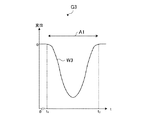
図8は、車両5の速度算出例を説明する図である。図8に示すグラフG3の横軸は時間を示し、縦軸は床版4dの垂直方向の変位を示す。グラフG3の波形W3は、車両5の床版4d上の走行によって生じる床版4dの垂直方向変位を示している。
FIG. 8 is a diagram illustrating an example of calculating the speed of the
車両5が、床版4dに進入し、中央部(加速度センサー2が取り付けられている位置)に向かって走行すると、床版4dの垂直方向変位の絶対値は車両5の荷重により徐々に大きくなる。そして、車両5が、床版4dの中央部を通過したときに、床版4dの垂直方向変位の絶対値は最大となる。車両5が、中央部から離れていくと、床版4dの垂直方向変位の絶対値は徐々に小さくなる。
When the
従って、速度算出部22は、矢印A1に示す垂直方向変位の波幅から、床版4dを通過する車両5の通過時間を推定することができる。例えば、速度算出部22は、垂直方向加速度が「0」から負になったときの時刻t1と、負から「0」になったときの時刻t2との差から、車両5の通過時間を推定することができる。具体的には、速度算出部22は、「t2−t1」より、車両5の通過時間を推定することができる。なお、時刻t1は、車両5が床版4dに進入した時刻であり、時刻t2は、車両5が床版4dを退出した時刻である。
Therefore, the
車両5の通過時間が分かれば、床版4d上を走行する車両5の速度を求めることができる。速度算出部22は、車両5の通過時間を、床版4dの長さ(例えば、30m)で除算することにより、車両5の速度を算出できる。
If the passing time of the
図4の説明に戻る。車線判定部23には、フィルター部21から出力される、床版4dの固有共振周波数成分が抑制された幅員方向加速度が入力される。車線判定部23は、入力された幅員方向加速度から、床版4d上の車両5が走行する車線を判定する。
Returning to the description of FIG. The width direction acceleration in which the natural resonance frequency component of the
図9は、車両5の走行車線判定の例を説明する図のその1である。図9には、図2に示した床版4dと、主桁4f〜4iとの断面が示してある。また、図9には、床版4dに取り付けられた加速度センサー2が示してある。
FIG. 9 is a first diagram illustrating an example of determining the traveling lane of the
図9に示す一点鎖線のモデルM1は、車両5が床版4d上を走行していないときの床版4dの位置を示している。実線のモデルM2は、車両5が床版4d上の矢印A2aに示す車線(加速度センサー2から遠い車線)を走行したときの床版4dの位置を示している。
The dashed-dot model M1 shown in FIG. 9 indicates the position of the
車両5が、床版4d上の矢印A2aに示す車線を走行すると、床版4dは、車両5の荷重によって、モデルM2に示すように、図中右側の端が左側の端より鉛直上方に傾く。そのため、床版4dに取り付けられた加速度センサー2のz軸は、点線矢印A2bに示すように、水平方向から、上方に傾く。
When the
図10は、車両5の走行車線判定の例を説明する図のその2である。図10において、図9と同じものには同じ符号が付してある。
FIG. 10 is a second diagram illustrating an example of determining the traveling lane of the
図10に示す一点鎖線のモデルM3は、車両5が床版4d上を走行していないときの床版4dの位置を示している。実線のモデルM4は、車両5が床版4d上の矢印A3aに示す車線(加速度センサー2から近い車線)を走行したときの床版4dの位置を示している。
A chain line model M3 shown in FIG. 10 indicates the position of the
車両5が、床版4d上の矢印A3aに示す車線を走行すると、床版4dは、車両5の荷重によって、モデルM4に示すように、図中右側の端が左側の端より鉛直下方に傾く。そのため、床版4dに取り付けられた加速度センサー2のz軸は、点線矢印A3bに示すように、水平方向から、下方に傾く。
When the
加速度センサー2のz軸は、図9の点線矢印A2bおよび図10の点線矢印A3bに示すように、車両5が走行する車線によって、水平方向に対し、上方および下方のどちらか一方を向く。従って、車線判定部23は、加速度センサー2から出力される幅員方向加速度の符号に基づいて、車両5が走行している車線を判定できる。
As shown by a dotted arrow A2b in FIG. 9 and a dotted arrow A3b in FIG. 10, the z-axis of the
図4の説明に戻る。変換部24には、フィルター部21から出力される、車両5のインパクトによる垂直方向加速度が入力される。変換部24は、入力された垂直方向加速度の包絡線の時間変化を、車両5と加速度センサー2との距離に対する変化に変換する。
Returning to the description of FIG. The vertical acceleration due to the impact of the
図11は、変換部24に入力される垂直方向加速度の例を説明する図である。図11に示すグラフG4の横軸は時間を示し、縦軸は加速度を示す。グラフG4の波形W4aは、変換部24に入力される、車両5のインパクトによる垂直方向加速度を示している。図11に示す時刻t1は、車両5が床版4dに進入した時刻を示し、時刻t2は、車両5が床版4dを退出した時刻を示している。
FIG. 11 is a diagram illustrating an example of the vertical acceleration input to the conversion unit 24. The horizontal axis of the graph G4 shown in FIG. 11 indicates time, and the vertical axis indicates acceleration. The waveform W4a of the graph G4 indicates the vertical acceleration due to the impact of the
変換部24は、入力された垂直方向加速度(波形W4a)の包絡線を算出する。例えば、変換部24は、入力された垂直方向加速度の絶対値を算出し、その絶対値の包絡線を算出する。グラフG4の波形W4bは、入力された垂直方向加速度の包絡線を示している。 The conversion unit 24 calculates the envelope of the input vertical acceleration (waveform W4a). For example, the conversion unit 24 calculates the absolute value of the input vertical acceleration, and calculates the envelope of the absolute value. The waveform W4b of the graph G4 indicates the envelope of the input vertical acceleration.
グラフG4の横軸は時間である。従って、波形W4bは、垂直方向加速度の包絡線の時間に対する変化を示している。変換部24は、この垂直方向加速度の包絡線の時間に対する変化を、記憶部13に記憶されている車両5と加速度センサー2との距離に対する変化に変換する。例えば、変換部24は、速度算出部22によって算出された車両5の速度を用いて、垂直方向加速度の包絡線の時間に対する変化を、記憶部13に記憶されている車両5と加速度センサー2との距離に対する変化に変換する。
The horizontal axis of the graph G4 is time. Accordingly, the waveform W4b shows a change in the envelope of the vertical acceleration with respect to time. The conversion unit 24 converts the change of the envelope of the vertical acceleration with respect to time into a change with respect to the distance between the
より具体的には、速度算出部22によって算出された車両5の速度は、床版4d上の走行線L1,L2(図5参照)を走行する車両5の単位時間あたりの移動距離を示している。従って、時々刻々における車両5の走行線L1,L2上の位置(x)が分かり、時々刻々における車両5と加速度センサー2との距離(D)が分かるため、変換部24は、垂直方向加速度の包絡線の時間(時々刻々)に対する変化を、車両5と加速度センサー2との距離に対する変化に変換できる。
More specifically, the speed of the
なお、図6の波形W1a,W1bに示したように、車両5と加速度センサー2との距離の関係は、車両5が走行する車線によって異なる。変換部24は、車線判定部23によって判定された車線に基づいて、参照すべき記憶部13の車両5と加速度センサー2との距離の関係を切替える。例えば、変換部24は、車線判定部23によって、車両5が加速度センサー2から遠い車線を走行していると判定された場合、図6の波形W1aを参照して、垂直方向加速度の包絡線の時間に対する変化を、車両5と加速度センサー2との距離に対する変化に変換する。
As shown in waveforms W1a and W1b in FIG. 6, the relationship between the distance between
図12は、車両5と加速度センサー2との距離に対する垂直方向加速度の包絡線の変化例を示した図である。図11に示すグラフG5の横軸は、床版4d上の車線を走行する車両5と加速度センサー2との距離を示し、縦軸は、垂直方向加速度の包絡線の振幅を示している。
FIG. 12 is a diagram illustrating an example of a change in the envelope of the vertical acceleration with respect to the distance between the
波形W5は、床版4d上の車線を走行する車両5と加速度センサー2との距離に対する、垂直方向加速度の包絡線の変化を示している。すなわち、波形W5は、図11に示した波形W4bの時間軸を、車両5と加速度センサー2との距離に変換したときの垂直方向加速度の包絡線の変化を示している。
The waveform W5 indicates a change in the envelope of the vertical acceleration with respect to the distance between the
なお、図12では、橋の長さを「30m」とし、車両5が走行線L1を走行している場合の包絡線の変化を示している(−15m≦x≦15m、l=4.6m)。従って、グラフG5の横軸は式(1)より、15.7(≒(152+4.62)1/2)…4.6…15.7と変化している(図6の縦軸を参照)。
FIG. 12 shows a change in the envelope when the length of the bridge is “30 m” and the
上記したように車両5は、床版4d上を走行しているとき、床版4dにインパクトを与えながら走行しているといえる。従って、床版4dに与えられるインパクトの位置は、時々刻々と変化している。例えば、床版4dに与えられるインパクトの位置は、図5に示した走行線L1,L2上において、時々刻々と変化している。なお、床版4dに与えられるインパクトの位置は、走行線L1,L2上において、一定に変化する。速度算出部22によって算出される車両5の速度(車両5の単位時間あたりの移動距離)は、床版4d上を走行する車両5の平均速度だからである。
As described above, when traveling on the
以上より、グラフG5の波形W5は、走行線L1,L2上のある位置において与えられたインパクトが、加速度センサー2に到達したときの振幅を示しているといえる。言い換えれば、波形W5は、加速度センサー2からある距離離れた位置で与えられたインパクトの、加速度センサー2の位置における振幅を示しているといえる。従って、波形W5から、床版4dの減衰係数を求めることができる。例えば、波形W5と減衰モデルが示す波形とを比較することにより、床版4dの減衰係数を求めることができる。
From the above, it can be said that the waveform W5 of the graph G5 indicates the amplitude when the impact given at a certain position on the traveling lines L1 and L2 reaches the
図4の説明に戻る。減衰係数算出部25は、変換部24によって距離に対する変化に変換された、インパクトによる垂直方向加速度の包絡線に基づいて、床版4dの減衰係数を算出する。
Returning to the description of FIG. The damping
図13は、減衰係数の算出の例を説明する図である。図13に示すグラフG6の横軸は、床版4d上を走行する車両5と加速度センサー2との距離を示し、縦軸は、垂直方向加速度の包絡線の振幅を示している。
FIG. 13 is a diagram illustrating an example of calculation of the attenuation coefficient. The horizontal axis of the graph G6 illustrated in FIG. 13 indicates the distance between the
減衰係数算出部25は、距離に対する変化に変換されたインパクトによる垂直方向加速度の包絡線を、その中央部で折り返す。例えば、減衰係数算出部25は、図12に示した波形W5の左半分を、その中央部(例えば、「距離=4.6」)において折り返す。図13に示す波形W6aは、図12の波形W5の左半分を中央部で折り返した波形を示し、波形W6bは、図12の波形W5の右半分の波形を示している。
The damping
減衰係数算出部25は、減衰モデルの波形を、変換部24によって変換された垂直方向加速度の包絡線の半分の波形と、もう半分の折り返した波形とに最も近くなるように調整(フィッティング)する。減衰モデルは、例えば、ボルニッツ式であり、次の式(2)で示される。
The damping
例えば、グラフG6の波形W6cは、ボルニッツ式の波形を示している。減衰係数算出部25は、ボルニッツ式の波形W6cが、2つの波形W6a,W6bと最も近くなるように、式(2)の「β」および「α」を調整する。
For example, a waveform W6c of the graph G6 indicates a Bornitz type waveform. The attenuation
ボルニッツ式の指数項「α」は、構造物の減衰係数を示している。従って、減衰係数算出部25は、2つの波形W6a,W6bに最も近くなった波形W6cの指数項「α」から、床版4dの減衰係数を算出(取得)できる。
The exponential term “α” in the Bornitz equation indicates the damping coefficient of the structure. Therefore, the attenuation
なお、減衰係数算出部25は、インパクトによる垂直方向加速度の包絡線を、その中央部で折り返さなくてもよい。例えば、減衰係数算出部25は、波形W5の左半分および右半分の一方の波形に、減衰モデルの波形をフィッティングさせてもよい。
Note that the attenuation
また、上記では、グラフG6の横軸を、床版4d上を走行する車両5と加速度センサー2との距離としたが、床版4d上の加速度センサー2の距離をゼロとした車線上の距離をグラフG6の横軸としてもよい。
In the above description, the horizontal axis of the graph G6 is the distance between the
図4の説明に戻る。推定部26は、減衰係数算出部25によって算出された床版4dの減衰係数に基づいて、床版4dの異常発生を推定する。例えば、推定部26は、減衰係数算出部25によって算出された床版4dの減衰係数を時系列に取得する。そして、推定部26は、減衰係数の時系列における値が、所定期間内において、所定量を超えてシフトした場合、床版4dに異常が発生したと判定する。
Returning to the description of FIG. The
推定部26は、このように床版4dの異常発生を推定することにより、外環境による減衰係数の変化と、床版4dの亀裂等の異常による減衰係数の変化とを区別することができる。例えば、床版4dの減衰係数は、温度、降雪、降雨、風などの外環境によって変動する。
By estimating the occurrence of an abnormality in the
一方、過積載の車両5が床版4d上を通過し、床版4dにダメージが生じたとする。こ
の場合、減衰係数の時系列における値は、所定期間内において、所定量を超えてシフトする
。推定部26は、減衰係数の時系列における値が、所定期間内において所定量を超えてシ
フトした場合に、床版4dに異常が発生したと推定するので、ストレス等による床版4d
の異常発生を適切に推定できる。
On the other hand, it is assumed that the
It is possible to properly estimate the occurrence of abnormalities.
なお、出力部14は、推定部26によって推定された異常発生の結果を、表示装置に出力する。
Note that the
図14は、計測装置1の動作例を示したフローチャートである。計測装置1は、例えば、所定の周期において、図14のフローチャートの処理を実行する。なお、記憶部13には、車両5の走行線L1,L2ごとにおける、車両5と加速度センサー2との間の距離の関係が記憶されているとする。また、通信部12は、加速度センサー2から受信した加速度を記憶部13に記憶しているとする。
FIG. 14 is a flowchart illustrating an operation example of the measuring device 1. The measuring device 1 executes, for example, the process of the flowchart in FIG. 14 in a predetermined cycle. It is assumed that the
まず、フィルター部21は、記憶部13に記憶されている加速度センサー2の加速度を取得し、取得した加速度のフィルタリング処理を行う(ステップS1)。例えば、フィルター部21は、LPFによって、車両5の荷重によって生じる、床版4dの撓みによる周波数成分の垂直方向加速度および幅員方向加速度を通過させる。また、フィルター部21は、BPFによって、車両5のインパクトによる周波数成分の垂直方向加速度を通過させる。
First, the
次に、速度算出部22は、ステップS1にてフィルタリング処理された、車両5の荷重によって生じる、床版4dの撓みによる垂直方向加速度に基づいて、床版4dを通過する車両5の通過速度を算出する(ステップS2)。
Next, the
次に、車線判定部23は、ステップS1にてフィルタリング処理された、車両5の荷重によって生じる、床版4dの撓みによる幅員方向加速度に基づいて、車両5が走行している床版4dの車線を判定する(ステップS3)。
Next, the
次に、変換部24は、ステップS1にてフィルタリング処理された、車両5のインパクトによる垂直方向加速度の包絡線を算出する(ステップS4)。例えば、変換部24は、図11に示す波形W4bを算出する。
Next, the conversion unit 24 calculates the envelope of the vertical acceleration due to the impact of the
次に、変換部24は、ステップS2にて算出された車両5の速度を用いて、ステップS4にて算出された包絡線の時間に対する変化を、記憶部13に記憶されている車両5と加速度センサー2との距離に対する変化に変換する(ステップS5)。このとき、変換部24は、ステップS3にて判定された車線に基づいて、記憶部13に記憶されている、走行線L1,L2ごとにおける車両5と加速度センサー2との距離の関係を選択する。これにより、ステップS4にて算出された包絡線(図11の波形W4b)の時間軸は、図12の波形W5に示すように、車両5と加速度センサー2との距離の軸に変換される。
Next, the conversion unit 24 uses the speed of the
次に、減衰係数算出部25は、ステップS5にて距離の軸に変換された、インパクトによる垂直方向加速度の包絡線に、減衰モデルが示す波形をフィッティングさせる(ステップS6)。
Next, the attenuation
次に、減衰係数算出部25は、ステップS6にてフィッティングさせた減衰モデルの波形の式の指数項から、床版4dの減衰係数を算出する(ステップS7)。
Next, the attenuation
次に、推定部26は、ステップS7にて算出された減衰係数の時系列における値が、所定の期間内において、所定量を超えてシフトしたか否か判定する(ステップS8)。推定部26は、減衰係数の時系列における値が、所定の期間内において、所定量を超えてシフトしたと判定した場合(S8の「Yes」)、処理をステップS9に移行する。推定部26は、減衰係数の時系列における値が、所定の期間内において、所定量を超えてシフトしていないと判定した場合(S8の「No」)、当該フローチャートの処理を終了する。
Next, the estimating
推定部26は、ステップS8にて、減衰係数の時系列における値が、所定の期間内において、所定量を超えてシフトしていると判定した場合(S8の「Yes」)、床版4dに異常が発生したと推定する(ステップS9)。
If the estimating
次に、出力部14は、ステップS9にて推定された異常発生を表示装置に出力する(ステップS10)。そして、出力部14は、当該フローチャートの処理を終了する。
Next, the
なお、上記フローチャートでは、計測装置1は、所定の周期において、図14のフローチャートの処理を実行するとしたが、通信部12が加速度センサー2から加速度を受信したときに、図14のフローチャートの処理を実行してもよい。
In the above flowchart, the measuring device 1 executes the process of the flowchart of FIG. 14 in a predetermined cycle. However, when the
また、ステップS2の処理とステップS3の処理は、順序が逆になってもよい。 Further, the order of the process of step S2 and the process of step S3 may be reversed.
このように、計測装置1の変換部24は、加速度センサー2の信号の時間変化を、床版4d上を走行する車両5と加速度センサー2との距離に対する変化に変換する。そして、減衰係数算出部25は、変換部24によって距離に対する変化に変換された信号に基づいて、床版4dの減衰係数を算出する。これにより、計測装置1は、車両5の床版4d上の走行から、床版4dの減衰係数を容易に得ることができる。
As described above, the conversion unit 24 of the measurement device 1 converts the time change of the signal of the
なお、上記では、加速度センサー2を床版4dに設置し、床版4dの振動を加速度として検出したが、床版4dに振動センサーやマイクロフォン等を設置してもよい。そして、計測装置1は、振動センサーやマイクロフォンから得られる信号から、床版4dの減衰係数を算出してもよい。すなわち、計測装置1は、床版4dを伝わる振動の振幅信号または音信号から、床版4dの減衰係数を算出してもよい。
In the above description, the
また、変換部24は、車両のインパクトによる垂直方向加速度の包絡線を算出したが、車両のインパクトによる幅員方向加速度の包絡線を算出してもよい。そして、減衰係数算出部25は、車両5のインパクトによる幅員方向加速度の包絡線に基づいて、減衰係数を算出してもよい。なお、垂直方向加速度の方が、幅員方向加速度より大きく変化するので、変換部24は、垂直方向加速度の包絡線を算出するのが望ましい。
Further, the conversion unit 24 calculates the envelope of the vertical acceleration due to the impact of the vehicle, but may calculate the envelope of the acceleration in the width direction due to the impact of the vehicle. Then, the damping
また、減衰係数算出部25は、床版4dの減衰係数を算出するとしたが、減衰率や対数減衰率を算出してもよい。減衰係数算出部25は、次の式によって、床版4dの減衰率ζおよび対数減衰率δを算出できる。
Further, the damping
ζ=(−r/ω) ζ = (-r / ω)
δ=2πζ δ = 2πζ
上記式の「r」は、減衰係数である。「ω」は、フィルター部21から出力される、インパクトによる垂直方向加速度の周波数(例えば、40Hz)である。
“R” in the above equation is an attenuation coefficient. “Ω” is the frequency (for example, 40 Hz) of the vertical acceleration due to the impact output from the
また、記憶部13には、3車線以上における車両5と加速度センサー2との距離の関係を記憶してもよい。これにより、計測装置1は、床版4dが3以上の車線を有する場合でも、減衰係数を算出できる。なお、この場合、車線判定部23は、幅員方向加速度の符号に加え、幅員方向加速度の大きさに基づいて、車両5がどの車線を走行しているか判定する。
Further, the
また、計測装置1は、算出した減衰係数とともに、床版4d上を走行する車両5の運動解析結果を出力部14に出力してもよい。例えば、速度算出部22は、算出した車両5の速度を出力部14に出力してもよい。また、速度算出部22は、図8に示した垂直方向変位の大きさから、車両5の重量を算出し、出力部14に出力してもよい。また、車線判定部23は、判定した車両5の走行車線を出力部14に出力してもよい。
The measuring device 1 may output the motion analysis result of the
また、上記では、変換部24は、記憶部13に記憶されている車線を走行する車両5と、床版4dに設けられた加速度センサー2との間の距離の関係を用いて、加速度センサー2から出力される加速度を、時間軸の信号から距離の軸の信号に変換したがこれに限られない。例えば、変換部24は、走行線が不明の場合、車両5に搭載されたGPS(慣性航法システム)から車両5の位置情報を取得し、加速度の時間軸の信号を距離の軸に変換してもよい。また、車両5の位置情報は、走行線が円軌道を描く場合、回転方位角から取得されることもできる。また、移動体の軌道が固定されている場合(例えば、ジェットコースター等のレール)、移動体の位置情報は、軌道情報を用いて取得されることもできる。また、移動体の位置が制御される場合(例えば、大型プリンターのヘッド等)、移動体の位置情報は、移動体の位置を制御する制御器から取得されることもできる。また、移動体の位置情報は、撮像装置から取得されることもできる。
In the above description, the conversion unit 24 uses the relationship between the distance between the
また、減衰係数を算出する構造物および構造物上を移動する移動体は、橋梁4および車両5に限られない。駐車場、ジェットコースター等の遊戯施設、または大型プリンターなどの大型機械装置にも適用することができる。
Further, the structure for calculating the damping coefficient and the moving body moving on the structure are not limited to the
[変形例]床版4dに車両5が進入する前、または床版4dから車両5が退出した後においても、床版4dに加速度が生じている場合がある。例えば、車両5が床版4dに近づくとき、または床版4dから遠ざかるとき、車両5の振動が、橋脚4aや橋台4b、隣接する床版4eを介して、床版4dに伝達する場合がある。
[Modification] Even before the
このような場合、加速度センサー2は、車両5が床版4d上を走行していないときの加速度も検出する。そのため、変換部24は、床版4d上における、車両5のインパクトによる包絡線を適切に算出できない。例えば、床版4dに伝達する振動によって、図11に示した時刻t1の前および時刻t2の後においても、垂直方向加速度が検出される。そのため、変換部24は、床版4d上を走行していないときの包絡線も、車両5のインパクトによる垂直方向加速度の包絡線として算出してしまう。
In such a case, the
そこで、車両5の床版4dへの進入および退出を検出する検出装置を橋梁4に設置する。例えば、赤外線センサー等の車両5の通過を検出する検出装置を、床版4dの車両5が入退出する位置に設置する。
Therefore, a detection device for detecting the entry and exit of the
変換部24は、検出装置による、車両5の床版4dへの進入および退出の検出タイミングに応じて、車両5の床版4dへの進入時刻および退出時刻を取得する。そして、変換部24は、フィルター部21から出力される垂直方向加速度に対し、車両5の床版4dへの進入時刻から退出時刻までを切り出す(抽出する)。これにより、変換部24は、床版4d上を走行する車両5のインパクトによる垂直方向加速度を適切に取得でき、その包絡線を適切に算出できる。
The conversion unit 24 acquires the entry time and the exit time of the
同様に、速度算出部22も、床版4dに伝達する振動によって、速度を適切に算出できない場合がある。例えば、床版4dに伝達する振動によって、図8に示した時刻t1の前および時刻t2の後においても、垂直方向変位が出現した場合、速度算出部22は、床版4d上を通過する車両5の速度を適切に算出できない。
Similarly, the
そこで、速度算出部22は、検出装置による、車両5の床版4dへの進入および退出の検出タイミングに応じて、車両5の床版4dへの進入時刻および退出時刻を取得する。速度算出部22は、取得した進入時刻および退出時刻から、適切に床版4d上を走行する車両5の速度を算出することができる。
Therefore, the
以上、本発明について実施形態を用いて説明したが、計測装置1の機能構成は、計測装置1の構成を理解容易にするために、主な処理内容に応じて分類したものである。構成要素の分類の仕方や名称によって、本願発明が制限されることはない。計測装置1の構成は、処理内容に応じて、さらに多くの構成要素に分類することもできる。また、1つの構成要素がさらに多くの処理を実行するように分類することもできる。また、各構成要素の処理は、1つのハードウェアで実行されてもよいし、複数のハードウェアで実行されてもよい。 As described above, the present invention has been described using the embodiment. However, the functional configuration of the measuring device 1 is classified according to main processing contents in order to make the configuration of the measuring device 1 easy to understand. The invention of the present application is not limited by the way of classification and names of the components. The configuration of the measuring device 1 can be classified into more components according to the processing content. In addition, it can be classified so that one component performs more processing. Further, the processing of each component may be executed by one piece of hardware, or may be executed by a plurality of pieces of hardware.
また、上述したフローチャートの各処理単位は、計測装置1の処理を理解容易にするために、主な処理内容に応じて分割したものである。処理単位の分割の仕方や名称によって、本願発明が制限されることはない。計測装置1の処理は、処理内容に応じて、さらに多くの処理単位に分割することもできる。また、1つの処理単位がさらに多くの処理を含むように分割することもできる。 In addition, each processing unit in the above-described flowchart is divided according to main processing contents in order to facilitate understanding of the processing of the measuring device 1. The present invention is not limited by the way of dividing the processing unit or the name. The processing of the measuring device 1 can be divided into more processing units according to the processing content. Further, it is also possible to divide the processing unit so that one processing unit includes more processing.
また、本発明の技術的範囲は上記実施形態に記載の範囲には限定されない。上記実施形態に多様な変更または改良を加えることが可能であることが当業者には明らかである。また、そのような変更または改良を加えた形態も本発明の技術的範囲に含まれ得ることが、特許請求の範囲の記載から明らかである。また、本発明は、計測装置1の減衰係数算出方法、および計測装置1の減衰係数算出方法を実現するプログラム、および当該プログラムを記憶した記憶媒体として提供することもできる。 Further, the technical scope of the present invention is not limited to the scope described in the above embodiment. It is apparent to those skilled in the art that various changes or improvements can be made to the above embodiment. It is apparent from the description of the claims that the embodiments with such changes or improvements can be included in the technical scope of the present invention. Further, the present invention can also be provided as an attenuation coefficient calculation method of the measurement device 1, a program for realizing the attenuation coefficient calculation method of the measurement device 1, and a storage medium storing the program.
1…計測装置、2…加速度センサー、3…通信ネットワーク、4…橋梁、4a…橋脚、4b,4c…橋台、4d,4e…床版、4da…側面、5…車両、4f〜4i…主桁、11…制御部、12…通信部、13…記憶部、14…出力部、15…操作部、21…フィルター部、22…速度算出部、23…車線判定部、24…変換部、25…減衰係数算出部、26…推定部。 DESCRIPTION OF SYMBOLS 1 ... Measurement apparatus, 2 ... Acceleration sensor, 3 ... Communication network, 4 ... Bridge, 4a ... Pier, 4b, 4c ... Abutment, 4d, 4e ... Floor slab, 4da ... Side, 5 ... Vehicle, 4f-4i ... Main girder , 11 ... control unit, 12 ... communication unit, 13 ... storage unit, 14 ... output unit, 15 ... operation unit, 21 ... filter unit, 22 ... speed calculation unit, 23 ... lane judgment unit, 24 ... conversion unit, 25 ... Damping coefficient calculation unit, 26... Estimation unit.
Claims (11)
前記距離に対する変化に変換された前記信号情報に基づいて、前記構造物の減衰特性を算出する減衰特性算出部と、
を有することを特徴とする計測装置。 A time change of signal information output from a vibration detection device provided in a structure, a moving body moving on the structure, a speed calculation unit for calculating a speed of the moving body, and an output from the vibration detection device. A conversion unit that converts a time change of the signal information to a change with respect to a distance between the vibration detection device using the speed of the moving body ,
Based on the signal information converted into a change with respect to the distance, an attenuation characteristic calculation unit that calculates an attenuation characteristic of the structure,
A measuring device comprising:
前記振動検出装置は、前記移動体の移動方向を規制する移動方向規制手段の規制方向に沿って延在する前記構造物の側端部であって、前記側端部の前記規制方向に沿う方向の中央部に設けられる、
ことを特徴とする計測装置。 The measuring device according to claim 1,
The vibration detection device is a side end of the structure extending along a restriction direction of a movement direction restriction unit that restricts a movement direction of the moving body, and a direction along the restriction direction of the side end. Provided in the center of the
A measuring device characterized by the above-mentioned.
前記信号情報は、前記構造物の前記移動体が移動する面の垂直方向加速度情報または幅員方向加速度情報である、
ことを特徴とする計測装置。 The measuring device according to claim 1,
The signal information is vertical acceleration information or width-direction acceleration information of a surface on which the moving body of the structure moves,
A measuring device characterized by the above-mentioned.
前記変換部は、前記構造物が有する固有共振の周波数成分および前記移動体の荷重によって生じる前記構造物の撓みによる周波数成分以外の所定の周波数成分の前記信号情報を、前記距離に対する変化に変換する、
ことを特徴とする計測装置。 The measuring device according to claim 1,
The conversion unit converts the signal information of a predetermined frequency component other than the frequency component of the natural resonance of the structure and the frequency component due to the bending of the structure caused by the load of the moving body into a change with respect to the distance. ,
A measuring device characterized by the above-mentioned.
前記減衰特性算出部は、前記信号情報の距離に対する波形情報と、前記構造物の減衰モデルで示される距離に対して減衰する波形情報とに基づいて、前記構造物の減衰特性を算出する、
ことを特徴とする計測装置。 The measuring device according to claim 1,
The attenuation characteristic calculation unit calculates the attenuation characteristic of the structure based on the waveform information for the distance of the signal information and the waveform information that attenuates for the distance indicated by the attenuation model of the structure.
A measuring device characterized by the above-mentioned.
前記減衰特性に基づいて、前記構造物の異常発生を推定する推定部、
をさらに有することを特徴とする計測装置。 The measuring device according to claim 1,
An estimating unit that estimates the occurrence of an abnormality in the structure based on the damping characteristic,
A measuring device, further comprising:
前記異常発生の結果を出力する出力部、
をさらに有することを特徴とする計測装置。 The measuring device according to claim 6 ,
An output unit that outputs a result of the abnormality occurrence;
A measuring device, further comprising:
前記変換部は、検出装置によって検出された前記移動体の前記構造物への進入および退出に基づいて、前記移動体が前記構造物上を移動しているときの前記信号情報を抽出し、前記距離に対する変化に変換する、
ことを特徴とする計測装置。 The measuring device according to claim 1,
The conversion unit is configured to extract the signal information when the moving body is moving on the structure, based on the approach and retreat of the moving body to the structure detected by a detection device, Convert to change over distance,
A measuring device characterized by the above-mentioned.
前記距離に対する変化に変換された前記信号情報に基づいて、前記構造物の減衰特性を算出する手順と、を含む
ことを特徴とする減衰特性算出方法。 The time change of the signal information output from the vibration detection device provided in the structure, the moving body moving on the structure, the procedure of calculating the speed of the moving body, and the time change of the signal information, Using a speed of a moving body to convert to a change with respect to a distance between the vibration detection device ,
Calculating a damping characteristic of the structure based on the signal information converted into the change with respect to the distance.
前記距離に対する変化に変換された前記信号情報に基づいて、前記構造物の減衰特性を算出する手順と、
をコンピューターに実行させることを特徴とするプログラム。 The time change of the signal information output from the vibration detection device provided in the structure, the moving body moving on the structure, the procedure of calculating the speed of the moving body, and the time change of the signal information, Using a speed of a moving body to convert to a change with respect to a distance between the vibration detection device ,
A step of calculating an attenuation characteristic of the structure based on the signal information converted into a change with respect to the distance,
A program that causes a computer to execute the program.
前記振動検出装置から出力される信号情報の時間変化を、前記構造物上を移動する移動体と、前記移動体の速度を算出する速度算出部と、前記振動検出装置から出力される前記信号情報の時間変化を前記移動体の速度を用いて前記振動検出装置との間の距離に対する変化に変換する変換部と、前記距離に対する変化に変換された前記信号情報に基づいて、前記構造物の減衰特性を算出する減衰特性算出部と、を有する計測装置と、
を有することを特徴とする計測システム。 A vibration detection device provided on the structure,
A time change of the signal information output from the vibration detecting device, a moving body moving on the structure, a speed calculating unit for calculating the speed of the moving body, and the signal information output from the vibration detecting device A conversion unit that converts the time change of the moving object into a change with respect to the distance between the vibration detection device and the vibration detection device using the speed of the moving body; A measurement device having an attenuation characteristic calculation unit for calculating characteristics,
A measurement system comprising:
Priority Applications (2)
| Application Number | Priority Date | Filing Date | Title |
|---|---|---|---|
| JP2015256335A JP6627501B2 (en) | 2015-12-28 | 2015-12-28 | Measuring device, damping characteristic calculating method, program, and measuring system |
| US15/381,547 US10768145B2 (en) | 2015-12-28 | 2016-12-16 | Measurement apparatus, attenuation characteristic calculation method, program, and measurement system |
Applications Claiming Priority (1)
| Application Number | Priority Date | Filing Date | Title |
|---|---|---|---|
| JP2015256335A JP6627501B2 (en) | 2015-12-28 | 2015-12-28 | Measuring device, damping characteristic calculating method, program, and measuring system |
Publications (3)
| Publication Number | Publication Date |
|---|---|
| JP2017120208A JP2017120208A (en) | 2017-07-06 |
| JP2017120208A5 JP2017120208A5 (en) | 2019-01-24 |
| JP6627501B2 true JP6627501B2 (en) | 2020-01-08 |
Family
ID=59087154
Family Applications (1)
| Application Number | Title | Priority Date | Filing Date |
|---|---|---|---|
| JP2015256335A Active JP6627501B2 (en) | 2015-12-28 | 2015-12-28 | Measuring device, damping characteristic calculating method, program, and measuring system |
Country Status (2)
| Country | Link |
|---|---|
| US (1) | US10768145B2 (en) |
| JP (1) | JP6627501B2 (en) |
Families Citing this family (14)
| Publication number | Priority date | Publication date | Assignee | Title |
|---|---|---|---|---|
| GB2533817A (en) | 2015-01-05 | 2016-07-06 | Bae Systems Plc | Mobile bridge module |
| GB2533818B (en) * | 2015-01-05 | 2021-03-03 | Bae Systems Plc | Mobile bridge apparatus |
| JP6604200B2 (en) | 2015-12-28 | 2019-11-13 | セイコーエプソン株式会社 | Accelerometer, measurement system, and measurement device |
| JP6587194B2 (en) * | 2016-02-15 | 2019-10-09 | パナソニックIpマネジメント株式会社 | Stress distribution measuring method and stress distribution measuring system |
| JP2019215203A (en) * | 2018-06-12 | 2019-12-19 | セイコーエプソン株式会社 | Display device, display method, program, recording medium, and structure monitoring system |
| CN109357822B (en) * | 2018-08-13 | 2021-06-01 | 东南大学 | Bridge rapid testing and evaluating method based on time-varying power characteristic change of axle coupling system |
| JP7396139B2 (en) | 2020-03-18 | 2023-12-12 | セイコーエプソン株式会社 | Measurement method, measurement device, measurement system and measurement program |
| JP7447586B2 (en) * | 2020-03-18 | 2024-03-12 | セイコーエプソン株式会社 | Measurement method, measurement device, measurement system and measurement program |
| JP2021147819A (en) | 2020-03-18 | 2021-09-27 | セイコーエプソン株式会社 | Measurement method, measurement apparatus, measurement system, and measurement program |
| JP7400566B2 (en) | 2020-03-18 | 2023-12-19 | セイコーエプソン株式会社 | Measurement method, measurement device, measurement system and measurement program |
| JP2021148537A (en) | 2020-03-18 | 2021-09-27 | セイコーエプソン株式会社 | Measuring method, measuring device, measuring system, and measuring program |
| JP7375637B2 (en) | 2020-03-18 | 2023-11-08 | セイコーエプソン株式会社 | Measurement method, measurement device, measurement system and measurement program |
| FR3115177B1 (en) * | 2020-10-12 | 2023-02-24 | Sercel Rech Const Elect | System and method for generating and collecting vibration data for monitoring a structure |
| AT524382B1 (en) * | 2020-10-16 | 2022-07-15 | Plasser & Theurer Export Von Bahnbaumaschinen Gmbh | Method and system for determining vibration transmission in the area of a track |
Family Cites Families (17)
| Publication number | Priority date | Publication date | Assignee | Title |
|---|---|---|---|---|
| JP2987411B2 (en) * | 1989-11-29 | 1999-12-06 | 清水建設株式会社 | Conduction and propagation phenomena measurement analysis method and system |
| EP1197726A1 (en) * | 2000-10-04 | 2002-04-17 | Eidgenössische Technische Hochschule Zürich | Multipurpose Sensor and cantilever for it |
| JP3837099B2 (en) * | 2002-08-08 | 2006-10-25 | ヤマト設計株式会社 | Structure damage estimation system and program |
| JP2005030786A (en) | 2003-07-07 | 2005-02-03 | Mitsubishi Heavy Ind Ltd | Method for measuring axle load and weight of bridge passing vehicle, and its device |
| US7802475B2 (en) * | 2006-10-13 | 2010-09-28 | Seiko Epson Corporation | Acceleration sensor |
| JP5375624B2 (en) * | 2010-01-18 | 2013-12-25 | セイコーエプソン株式会社 | Acceleration sensor and acceleration detection device |
| US9075077B2 (en) * | 2010-09-20 | 2015-07-07 | Analog Devices, Inc. | Resonant sensing using extensional modes of a plate |
| US8990032B2 (en) * | 2010-12-30 | 2015-03-24 | Sensys Networks, Inc. | In-pavement wireless vibration sensor nodes, networks and systems |
| JP5678741B2 (en) * | 2011-03-11 | 2015-03-04 | セイコーエプソン株式会社 | Acceleration detector, acceleration detection device, and electronic apparatus |
| JP5824876B2 (en) * | 2011-05-30 | 2015-12-02 | セイコーエプソン株式会社 | Manufacturing method of physical quantity detector |
| JP2013050321A (en) * | 2011-08-30 | 2013-03-14 | Seiko Epson Corp | Physical quantity detector and electronic apparatus |
| JP5896114B2 (en) * | 2011-10-31 | 2016-03-30 | セイコーエプソン株式会社 | Physical quantity detection device, physical quantity detector, and electronic device |
| JP2013122375A (en) * | 2011-11-07 | 2013-06-20 | Seiko Epson Corp | Physical quantity detection device, physical quantity detector and electronic apparatus |
| US9285281B1 (en) * | 2012-07-10 | 2016-03-15 | The United States Of America, As Represented By The Secretary Of The Army | Deflection plate for mobile dynamometer |
| JP2015098686A (en) * | 2013-11-18 | 2015-05-28 | 彬 小林 | Preventive maintenance monitoring system of structure |
| JP6432308B2 (en) * | 2014-11-25 | 2018-12-05 | 日本電気株式会社 | Measuring device and measuring range switching method |
| JP6604200B2 (en) | 2015-12-28 | 2019-11-13 | セイコーエプソン株式会社 | Accelerometer, measurement system, and measurement device |
-
2015
- 2015-12-28 JP JP2015256335A patent/JP6627501B2/en active Active
-
2016
- 2016-12-16 US US15/381,547 patent/US10768145B2/en active Active
Also Published As
| Publication number | Publication date |
|---|---|
| US10768145B2 (en) | 2020-09-08 |
| US20170184550A1 (en) | 2017-06-29 |
| JP2017120208A (en) | 2017-07-06 |
Similar Documents
| Publication | Publication Date | Title |
|---|---|---|
| JP6627501B2 (en) | Measuring device, damping characteristic calculating method, program, and measuring system | |
| JP6775213B2 (en) | Measuring equipment, measuring system, program and measuring method | |
| US10877061B2 (en) | Measurement instrument, measurement method, measurement system, and program | |
| US10198640B2 (en) | Measuring device, measuring system, measuring method, and program | |
| US20150336546A1 (en) | Method and system for vehicle to sense roadblock | |
| JP6551121B2 (en) | Measuring device, measuring method, measuring system, and program | |
| JP6645102B2 (en) | Measuring device, measuring system, measuring method, and program | |
| JP7375637B2 (en) | Measurement method, measurement device, measurement system and measurement program | |
| JP7147538B2 (en) | Measuring device and measuring system | |
| US20230054215A1 (en) | Abnormality estimation apparatus, abnormality estimation method, and computer-readable recording medium | |
| US20200247392A1 (en) | Measurement device, measurement system, and measurement method | |
| JP6592827B2 (en) | Apparatus, method, program, and recording medium for identifying weight of vehicle traveling on traffic road | |
| JP2016125229A (en) | Method, program and system for estimating damage state of structure | |
| US10203350B2 (en) | Measurement instrument, measurement method, measurement system, and program | |
| JP6686354B2 (en) | Measuring device, measuring method, measuring system, and program | |
| US10818166B2 (en) | Vehicle audible signal processing systems | |
| WO2012026517A1 (en) | Passage time estimation device, vehicle speed calculation method, and program | |
| JP4972211B2 (en) | Navigation device and speed estimation method | |
| JP6809172B2 (en) | Estimating method, estimation program and estimation device | |
| JP2021147820A (en) | Measurement method, measurement apparatus, measurement system, and measurement program | |
| US20230003611A1 (en) | Time Point Acquisition Method, Time Point Acquisition Device, Time Point Acquisition System, And Time Point Acquisition Program | |
| JP7294444B2 (en) | Vehicle weight estimation device, vehicle weight estimation method, and program | |
| US11982595B2 (en) | Determining abnormalities in the superstructure of a bridge based on acceleration data | |
| US20230003608A1 (en) | Derivation Method, Derivation Device, Derivation System, And Program | |
| US20230003610A1 (en) | Derivation Method, Derivation Device, Derivation System, And Program |
Legal Events
| Date | Code | Title | Description |
|---|---|---|---|
| RD04 | Notification of resignation of power of attorney |
Free format text: JAPANESE INTERMEDIATE CODE: A7424 Effective date: 20181207 |
|
| A521 | Request for written amendment filed |
Free format text: JAPANESE INTERMEDIATE CODE: A523 Effective date: 20181210 |
|
| A621 | Written request for application examination |
Free format text: JAPANESE INTERMEDIATE CODE: A621 Effective date: 20181210 |
|
| RD03 | Notification of appointment of power of attorney |
Free format text: JAPANESE INTERMEDIATE CODE: A7423 Effective date: 20181210 |
|
| A977 | Report on retrieval |
Free format text: JAPANESE INTERMEDIATE CODE: A971007 Effective date: 20190522 |
|
| A131 | Notification of reasons for refusal |
Free format text: JAPANESE INTERMEDIATE CODE: A131 Effective date: 20190604 |
|
| A521 | Request for written amendment filed |
Free format text: JAPANESE INTERMEDIATE CODE: A523 Effective date: 20190801 |
|
| TRDD | Decision of grant or rejection written | ||
| A01 | Written decision to grant a patent or to grant a registration (utility model) |
Free format text: JAPANESE INTERMEDIATE CODE: A01 Effective date: 20191105 |
|
| A61 | First payment of annual fees (during grant procedure) |
Free format text: JAPANESE INTERMEDIATE CODE: A61 Effective date: 20191118 |
|
| R150 | Certificate of patent or registration of utility model |
Ref document number: 6627501 Country of ref document: JP Free format text: JAPANESE INTERMEDIATE CODE: R150 |