JP6626295B2 - Image encoding device, image processing device, image encoding method - Google Patents
Image encoding device, image processing device, image encoding method Download PDFInfo
- Publication number
- JP6626295B2 JP6626295B2 JP2015177919A JP2015177919A JP6626295B2 JP 6626295 B2 JP6626295 B2 JP 6626295B2 JP 2015177919 A JP2015177919 A JP 2015177919A JP 2015177919 A JP2015177919 A JP 2015177919A JP 6626295 B2 JP6626295 B2 JP 6626295B2
- Authority
- JP
- Japan
- Prior art keywords
- quantization step
- encoding
- groups
- image
- block
- Prior art date
- Legal status (The legal status is an assumption and is not a legal conclusion. Google has not performed a legal analysis and makes no representation as to the accuracy of the status listed.)
- Expired - Fee Related
Links
Images


Classifications
-
- H—ELECTRICITY
- H04—ELECTRIC COMMUNICATION TECHNIQUE
- H04N—PICTORIAL COMMUNICATION, e.g. TELEVISION
- H04N19/00—Methods or arrangements for coding, decoding, compressing or decompressing digital video signals
- H04N19/60—Methods or arrangements for coding, decoding, compressing or decompressing digital video signals using transform coding
- H04N19/61—Methods or arrangements for coding, decoding, compressing or decompressing digital video signals using transform coding in combination with predictive coding
-
- H—ELECTRICITY
- H04—ELECTRIC COMMUNICATION TECHNIQUE
- H04N—PICTORIAL COMMUNICATION, e.g. TELEVISION
- H04N19/00—Methods or arrangements for coding, decoding, compressing or decompressing digital video signals
- H04N19/10—Methods or arrangements for coding, decoding, compressing or decompressing digital video signals using adaptive coding
- H04N19/102—Methods or arrangements for coding, decoding, compressing or decompressing digital video signals using adaptive coding characterised by the element, parameter or selection affected or controlled by the adaptive coding
- H04N19/103—Selection of coding mode or of prediction mode
-
- H—ELECTRICITY
- H04—ELECTRIC COMMUNICATION TECHNIQUE
- H04N—PICTORIAL COMMUNICATION, e.g. TELEVISION
- H04N19/00—Methods or arrangements for coding, decoding, compressing or decompressing digital video signals
- H04N19/10—Methods or arrangements for coding, decoding, compressing or decompressing digital video signals using adaptive coding
- H04N19/102—Methods or arrangements for coding, decoding, compressing or decompressing digital video signals using adaptive coding characterised by the element, parameter or selection affected or controlled by the adaptive coding
- H04N19/124—Quantisation
-
- H—ELECTRICITY
- H04—ELECTRIC COMMUNICATION TECHNIQUE
- H04N—PICTORIAL COMMUNICATION, e.g. TELEVISION
- H04N19/00—Methods or arrangements for coding, decoding, compressing or decompressing digital video signals
- H04N19/10—Methods or arrangements for coding, decoding, compressing or decompressing digital video signals using adaptive coding
- H04N19/134—Methods or arrangements for coding, decoding, compressing or decompressing digital video signals using adaptive coding characterised by the element, parameter or criterion affecting or controlling the adaptive coding
- H04N19/136—Incoming video signal characteristics or properties
- H04N19/14—Coding unit complexity, e.g. amount of activity or edge presence estimation
-
- H—ELECTRICITY
- H04—ELECTRIC COMMUNICATION TECHNIQUE
- H04N—PICTORIAL COMMUNICATION, e.g. TELEVISION
- H04N19/00—Methods or arrangements for coding, decoding, compressing or decompressing digital video signals
- H04N19/10—Methods or arrangements for coding, decoding, compressing or decompressing digital video signals using adaptive coding
- H04N19/134—Methods or arrangements for coding, decoding, compressing or decompressing digital video signals using adaptive coding characterised by the element, parameter or criterion affecting or controlling the adaptive coding
- H04N19/146—Data rate or code amount at the encoder output
-
- H—ELECTRICITY
- H04—ELECTRIC COMMUNICATION TECHNIQUE
- H04N—PICTORIAL COMMUNICATION, e.g. TELEVISION
- H04N19/00—Methods or arrangements for coding, decoding, compressing or decompressing digital video signals
- H04N19/10—Methods or arrangements for coding, decoding, compressing or decompressing digital video signals using adaptive coding
- H04N19/169—Methods or arrangements for coding, decoding, compressing or decompressing digital video signals using adaptive coding characterised by the coding unit, i.e. the structural portion or semantic portion of the video signal being the object or the subject of the adaptive coding
- H04N19/17—Methods or arrangements for coding, decoding, compressing or decompressing digital video signals using adaptive coding characterised by the coding unit, i.e. the structural portion or semantic portion of the video signal being the object or the subject of the adaptive coding the unit being an image region, e.g. an object
- H04N19/176—Methods or arrangements for coding, decoding, compressing or decompressing digital video signals using adaptive coding characterised by the coding unit, i.e. the structural portion or semantic portion of the video signal being the object or the subject of the adaptive coding the unit being an image region, e.g. an object the region being a block, e.g. a macroblock
-
- H—ELECTRICITY
- H04—ELECTRIC COMMUNICATION TECHNIQUE
- H04N—PICTORIAL COMMUNICATION, e.g. TELEVISION
- H04N19/00—Methods or arrangements for coding, decoding, compressing or decompressing digital video signals
- H04N19/50—Methods or arrangements for coding, decoding, compressing or decompressing digital video signals using predictive coding
- H04N19/593—Methods or arrangements for coding, decoding, compressing or decompressing digital video signals using predictive coding involving spatial prediction techniques
-
- H—ELECTRICITY
- H04—ELECTRIC COMMUNICATION TECHNIQUE
- H04N—PICTORIAL COMMUNICATION, e.g. TELEVISION
- H04N19/00—Methods or arrangements for coding, decoding, compressing or decompressing digital video signals
- H04N19/60—Methods or arrangements for coding, decoding, compressing or decompressing digital video signals using transform coding
- H04N19/625—Methods or arrangements for coding, decoding, compressing or decompressing digital video signals using transform coding using discrete cosine transform [DCT]
-
- H—ELECTRICITY
- H04—ELECTRIC COMMUNICATION TECHNIQUE
- H04N—PICTORIAL COMMUNICATION, e.g. TELEVISION
- H04N19/00—Methods or arrangements for coding, decoding, compressing or decompressing digital video signals
- H04N19/10—Methods or arrangements for coding, decoding, compressing or decompressing digital video signals using adaptive coding
- H04N19/169—Methods or arrangements for coding, decoding, compressing or decompressing digital video signals using adaptive coding characterised by the coding unit, i.e. the structural portion or semantic portion of the video signal being the object or the subject of the adaptive coding
- H04N19/182—Methods or arrangements for coding, decoding, compressing or decompressing digital video signals using adaptive coding characterised by the coding unit, i.e. the structural portion or semantic portion of the video signal being the object or the subject of the adaptive coding the unit being a pixel
Description
本発明は画像符号化装置、画像処理装置、画像符号化方法に関する。 The present invention relates to an image encoding device, an image processing device, and an image encoding method.
近年、デジタルビデオなどの撮像装置は高解像度化、高フレームレート化に伴って、システムで扱う画像データ量が著しく増加しており、画像メモリやバスインターフェース回路の高速化が要求されている。これに対し、画像メモリやバスインターフェースの前後で画像の圧縮符号化を行って、画像データ量を削減することで回路の高速化の要求に対応することができる。 2. Description of the Related Art In recent years, with the increase in resolution and frame rate of imaging devices for digital video and the like, the amount of image data handled by the system has increased remarkably, and higher speeds of image memories and bus interface circuits are required. On the other hand, by compressing and encoding an image before and after an image memory and a bus interface to reduce the amount of image data, it is possible to respond to a demand for a high-speed circuit.
この場合、画像圧縮のための符号化方式は回路規模が小型で、符号化遅延の小さいことが望まれる。そのため、従来のJPEGやMPEG2に代表されるDCTベースの符号化方式は不向きである。そこでDPCM(Differential Pulse Code Modulation:差分パルス符号変調)ベースの予測符号化方式での提案がされている(特許文献1を参照)。 In this case, it is desired that the encoding method for image compression has a small circuit scale and a small encoding delay. Therefore, the conventional DCT-based coding method represented by JPEG or MPEG2 is not suitable. Therefore, a proposal has been made of a DPCM (Differential Pulse Code Modulation) -based predictive coding method (see Patent Document 1).
しかし、DPCMベースの予測符号化方式では、画素レベルの変動が大きいエッジ部分の画質劣化が生じやすい。特許文献1の提案方式では、隣接画素データの差分値が所定の閾値以下であれば画質劣化の少ない符号化が可能である。しかし、急峻なエッジ部分のように隣接画素データの差分値が所定の閾値を超える場合、量子化により元の画素データビットを半分にする(例えば、10ビットから5ビットにする)必要があり、大きな画質劣化の原因になる。同様に、予測画像と符号化対象画像との差分が大きい場合にも、大きな画質劣化の原因となる。
However, in the DPCM-based predictive coding method, the image quality is likely to be degraded at the edge portion where the pixel level greatly varies. In the proposed method of
本発明は上記課題に鑑み、効率的に符号化を行い、急峻なエッジ部分など、画素間での差分が大きい部分での画質劣化を低減しつつ、更に隣接する符号化対象のブロックの境界部分での画質の劣化を低減すること目的とする。 The present invention has been made in view of the above problems, and performs efficient encoding to reduce image quality deterioration in a portion having a large difference between pixels, such as a steep edge portion, and further reduce a boundary portion between adjacent blocks to be encoded. The purpose of the present invention is to reduce the deterioration of the image quality in the image.
上記課題を解決するための本発明は、画像符号化装置であって、
それぞれが所定数の画素からなる複数のグループを含む符号化対象のブロックの符号長が所定値を超えないように、前記グループごとに、前記グループの画像データの符号化処理における量子化のための量子化ステップと符号化方式とを決定する決定手段と、
前記符号化対象のブロックについて、該ブロックに含まれる前記グループごとに前記決定手段が決定した前記量子化ステップと前記符号化方式とに基づき前記符号化処理を行って符号化データを生成する符号化手段と
を備え、
前記決定手段は、
前記グループごとに、量子化された画像データを出力する第1の符号化方式と、量子化された画像データと予測データとの差分を符号化したデータを出力する第2の符号化方式とのうち、符号長がより小さくなる符号化方式に決定し、
複数の量子化ステップのうち、少なくとも第1の量子化ステップと第2の量子化ステップの何れかを前記グループごとに決定し、
前記第1の量子化ステップは、前記符号化対象のブロックに含まれる前記グループの全てについて該第1の量子化ステップを用いて量子化を行い、該グループのそれぞれについて前記決定された符号化方式で符号化した場合の前記符号化対象のブロックの符号長が前記所定値を超えず、且つ、最大の値となる量子化ステップであって、
前記第2の量子化ステップは、前記第1の量子化ステップよりも小さい量子化ステップであって、前記複数のグループのうち、少なくとも前記符号化対象のブロックの先頭のグループと最後尾のグループとに割り当てられることを特徴とする。
The present invention for solving the above problems is an image encoding device,
In order to prevent the code length of an encoding target block including a plurality of groups each including a predetermined number of pixels from exceeding a predetermined value, for each of the groups, Determining means for determining a quantization step and a coding method,
Coding for generating the coded data by performing the coding process on the block to be coded based on the quantization step and the coding method determined by the determining unit for each of the groups included in the block. Means
With
The determining means comprises:
For each of the groups, a first encoding method for outputting quantized image data and a second encoding method for outputting data obtained by encoding the difference between the quantized image data and the prediction data Of these, the coding length is decided to be smaller,
At least one of the first quantization step and the second quantization step among the plurality of quantization steps is determined for each of the groups,
The first quantization step performs quantization using the first quantization step for all of the groups included in the block to be encoded, and determines the determined encoding scheme for each of the groups. In the quantization step, the code length of the block to be encoded does not exceed the predetermined value, and is the maximum value,
The second quantization step is a quantization step smaller than the first quantization step, and among the plurality of groups, at least a first group and a last group of the block to be encoded. Is characterized in that
本発明によれば画素間での差分が大きい部分での画質劣化を低減しつつ、更に隣接する符号化対象のブロックの境界部分での画質の劣化を低減することができる。 According to the present invention, it is possible to reduce image quality degradation at a portion where a difference between pixels is large and further reduce image quality degradation at a boundary portion between adjacent coding target blocks.
以下、添付の図面を参照しながら、発明の実施形態について詳細に説明する。 Hereinafter, embodiments of the present invention will be described in detail with reference to the accompanying drawings.
[実施形態1]
(画像処理装置の説明)
以下、発明の実施形態に対応する画像処理装置を説明する。図1(a)は発明の実施形態における画像処理装置の構成の一例を示す図である。画像処理装置100は、例えば取得部10、画像符号化部20、メモリ30を有する。図1の画像処理装置100において、各ブロックは、撮像素子や表示素子のような物理的デバイスを除き専用のデバイス、ロジック回路やメモリを用いてハードウェア的に構成されてもよい。或いは、メモリに記憶されている処理プログラムをCPU等のコンピュータが実行することにより、ソフトウェア的に構成されてもよい。画像処理装置100は例えばデジタルカメラとして実施することができるが、それ以外にも、例えばパーソナルコンピュータ、携帯電話、スマートフォン、PDA、タブレット端末、デジタルビデオカメラなどの任意の情報処理端末或いは撮像装置とすることができる。
[Embodiment 1]
(Description of image processing device)
Hereinafter, an image processing apparatus according to an embodiment of the present invention will be described. FIG. 1A is a diagram illustrating an example of a configuration of an image processing apparatus according to an embodiment of the present invention. The
図1(a)において、取得部10は画像データを入力する機能を有する。取得部10は、例えば、撮像センサを備える撮像部や、外部から伝送路を介して画像データを入力する構成を含む。或いは、取得部10は、記録媒体などから画像データを読み出す構成を含む。また、取得される画像データは、静止画データであってもよく、動画データであってもよい。取得部10が取得する画像データが動画データの場合、複数のフレームの動画データが連続的に取得されてもよい。
In FIG. 1A, the
取得部10は、取得した画像データを画像符号化部20に供給する。画像符号化部20は、取得部10から供給される画像データをパルス符号変調(PCM)または差分パルス符号変調(DPCM)のいずれかの符号化方式に従って符号化し、情報量が圧縮された符号化データを出力する。出力された符号化データは、メモリ30に記憶される。メモリ30は、画像符号化部20から出力された符号化データを記憶するために必要な記憶容量を有する。メモリ30に記憶された符号化データには後段の処理部において現像処理や更なる圧縮処理が実施される。
The
なお、図1(a)では、取得部、画像符号化部20及びメモリ30を独立した構成として示しているが、画像処理装置100に実装するに当り、これらを一体に例えば1チップに統合してもよいし、あるいは別体として独立に構成しても良い。
In FIG. 1A, the acquisition unit, the
(画像符号化部の説明)
以下、図1(b)を参照して、発明の実施形態に対応する画像符号化部20の構成を説明する。図1(b)は、発明の実施形態に係る画像符号化部20の構成例を示すブロック図である。以下、本実施形態の画像符号化部20の各ブロックの動作について説明する。
(Description of image encoding unit)
Hereinafter, the configuration of the image encoding
図1(a)に示した画像符号化部20は、仮符号化系110と本符号化系120の2つの大ブロックより構成される。さらに仮符号化系110は符号化部111A〜111D、QP決定部115から構成され、本符号化系120で本符号化を行う際に使用する量子化パラメータのセットを決定するように動作する。本符号化系120は遅延部121、符号化部111E、多重化部123で構成され、仮符号化系110で決定された量子化パラメータのセットを用いた量子化処理を含む本符号化を実行するように動作する。画像符号化部20は、画像符号化装置として専用のデバイス、ロジック回路やメモリを用いてハードウェア的に一体的に構成されても良いし、或いは、複数のデバイス等で分散して構成されてもよい。或いは、メモリに記憶されている処理プログラムをCPU等のコンピュータが実行することにより、ソフトウェア的に構成されてもよい。
The
(符号ブロックと画素グループの説明)
画像符号化部20には、外部から符号化対象となる画像データが入力端子101を介し、スキャン変換部130を経て入力される。本実施形態において画像符号化部20が実行する画像符号化処理では、入力画像データを所定サイズ(画素数)を有するブロック(以下、「符号化ブロック」という)に分割し、符号化ブロック単位に符号化を行うものとする。また、符号化ブロックは1つ以上の所定数の画素からなる「画素グループ」にさらに分割される。画素グループは後述する符号化方法(PCM/DPCM)の切り替えや、量子化パラメータ(以下、「QP」という)の切り替えを行う単位となる。画素グループは同一座標の画素や隣接画素など相関性の高い画素で構成されることが望ましく、単一のカラー要素のみで構成してもよいし、複数のカラー要素で構成してもよい。
(Description of code block and pixel group)
Image data to be encoded is externally input to the
取得部10からの画像データは、ラスタ走査の順に入力端子101に供給される。入力端子101からの画像データはラスタ走査の順にスキャン変換部130に入力される。スキャン変換部130は符号化ブロック毎に画像データを一旦保持し、奇数番目のブロックは画素のスキャン順を変えずに正順で出力し、各ラインの偶数番目のブロックはスキャン順を逆にして逆順で出力する。例えば、1番目の符号化ブロックは正順で出力され、2番目の符号化ブロックは逆順で出力される。ここで、逆順で出力するとは入力されたブロックの先頭画素を最後の画素として出力し、ブロックの最後の画素を先頭画素として出力するように変換して出力することをいう。これにより、同一ラインに含まれる複数のブロックにそれぞれ含まれる画素の並びが隣接するブロックの間で互いに正順と逆順とで異なるように並び替えられる。スキャン変換部130は偶数番目のブロックを正順で出力し、奇数番目のブロックを逆順で出力しても良い。
Image data from the
本実施形態では画像データの形式として、図4(a)及び図4(b)に示すRGB画像データを例として説明するが、他のデータ形式であっても良い。他のデータ形式の詳細は本実施形態の最後に図4(c)及び(d)を参照して説明する。また、画像データはラスタースキャン順に入力され、各カラー要素であるR(赤)、G(緑)、B(青)の各画素データは時分割に多重されており順次入力されるものとする。また各画素のビット深度は一例として10ビットとする。スキャン変換された画像データは図4(b)に示すように、画像データに含まれる各画素データの配置が逆順となる。これにより画像データはブロック毎に交互にスキャン順が変換されているブロック、変換されていないブロックとなり、このような画像データが仮符号化系110、本符号化系120に入力され符号化される。
In the present embodiment, the RGB image data shown in FIGS. 4A and 4B will be described as an example of the format of the image data, but other data formats may be used. Details of other data formats will be described at the end of the present embodiment with reference to FIGS. Further, it is assumed that the image data is input in the raster scan order, and that the R (red), G (green), and B (blue) pixel data of each color element are multiplexed in a time-division manner and are sequentially input. The bit depth of each pixel is, for example, 10 bits. In the scan-converted image data, as shown in FIG. 4B, the arrangement of the pixel data included in the image data is in the reverse order. As a result, the image data becomes a block in which the scan order is alternately converted for each block and a block which is not converted. Such image data is input to the
本実施形態では、RGB画像データの各カラー要素それぞれ水平16画素×垂直1画素×3色=48画素を符号化ブロックとする。また、各カラー要素の1画素ずつの計3画素を画素グループとする。 In the present embodiment, each of the color elements of the RGB image data is set to have 16 horizontal pixels × 1 vertical pixel × 3 colors = 48 pixels as an encoding block. In addition, a total of three pixels, one for each color element, are defined as a pixel group.
図4(a)は本実施形態における符号化ブロックを構成する画素データと、画素グループとの関係を説明するための図である。図4(a)に示すように、符号化ブロックは、R、G、Bの各カラー要素について16画素ずつから構成され、画素位置に応じてR、G、Bからなるカラー要素の組のそれぞれにグループ番号が割り当てられ、各画素には画素番号0から47までのいずれかがそれぞれ割り当てられている。例えば、各カラー要素の1画素目のデータであるR0、G0、B0はグループ番号が「0」の画素グループを構成し、2画素目のデータであるR1、G1、B1はグループ番号が「1」の画素グループを構成している。本実施形態では、各画素のデータのことを「画像データ」と呼ぶことにする。図4(b)は、スキャン変換部130から逆順に出力された符号化ブロックを構成する画素データと画素グループの関係を示す。ここでは元の順番が分かるようにグループ番号、画素番号、画像データを示しているが、画像符号化部20における処理は図4(a)の入力と同じものとして処理される。
FIG. 4A is a diagram for explaining the relationship between pixel data constituting a coding block and a pixel group in the present embodiment. As shown in FIG. 4A, the coding block is composed of 16 pixels for each of the R, G, and B color elements, and each of the sets of the R, G, and B color elements according to the pixel position. Is assigned a group number, and each pixel is assigned one of
(符号化部111の説明)
次に、仮符号化系110、本符号化系120で共通に使用される符号化部111の構成及び動作について、図3を参照して説明する。図3は符号化部111の構成例を示すブロック図である。図3に示すように、符号化部111は、例えば量子化部301、予測部302、減算器303、可変長符号化部304、PCM符号長算出部305、符号長比較部306、セレクタ307、308を含んで構成される。
(Description of encoding section 111)
Next, the configuration and operation of an
符号化部111には、画像データとQPとが入力される。仮符号化系110の場合、QPは符号化部111Aから111Dのそれぞれに対して固定値として予め割り当てられていてもよい。図1(b)では一例として、符号化部111Aから111Dまで順にQPとして0、1、2、3がそれぞれ割り当てられている場合を示している。仮符号化系110の場合、各符号化部が予めQPの値を保持していても良い。本符号化系120には、仮符号化系110で決定されたQPがQP決定部115から入力される。以下、符号化部111の具体的構成及びその動作について詳述する。
The image data and the QP are input to the
まず、符号化部111に入力された画像データは量子化部301に入力される。量子化部301は与えられたQPにより入力画像データを量子化し、量子化されたデータを予測部302、減算器303、セレクタ307にそれぞれ出力する。本発明では量子化部301で量子化された量子化データをPCMデータと呼ぶ。本実施形態では、QPの値を0を最小値とする整数値とし、0から3までの範囲で変更できるものとして説明するが、より大きなQPの値を設定して更に大きな量子化ステップを使用しても良い。
First, the image data input to the
本実施形態において量子化部301は、QPが小さいほど量子化ステップを小さく(細かく)し、QPが大きいほど量子化ステップを大きく(粗く)する。そして、QPが1増えるとPCMデータの有意ビットが1ビット減少するように量子化を行う。例えば、式1で表される量子化を行う。
Quant = Data / (1 << QP) ・・・式1
(Quant:量子化データ、Data:入力画像データ、QP:量子化パラメータである。)
In the present embodiment, the
Quant = Data / (1 << QP)
(Quant: quantization data, Data: input image data, QP: quantization parameter.)
また、1<<QPとは、入力された画像データが、QPで示されるビット数だけ、ビットシフトすることを示す。
式1のように量子化することよってQPに対する出力値、有意ビットは以下のようになる。
QP=0:量子化ステップ=1、入力データは量子化されずそのまま出力。有意ビット不変。
QP=1:量子化ステップ=2、入力データは1/2に量子化。有意ビットは1ビット減少。
QP=2:量子化ステップ=4、入力データは1/4に量子化。有意ビットは2ビット減少。
QP=n:量子化ステップ=(1<<n)、入力データは1/(1<<n)に量子化。有意ビットはnビット減少。
1 << QP indicates that the input image data is bit-shifted by the number of bits indicated by QP.
The output value and significant bits for QP by quantizing as in
QP = 0: quantization step = 1, input data is output without quantization. Significant bit invariant.
QP = 1: quantization step = 2, input data is quantized to 2. Significant bits are reduced by one bit.
QP = 2: quantization step = 4, input data is quantized to 1/4. Significant bits are reduced by 2 bits.
QP = n: quantization step = (1 << n), input data is quantized to 1 / (1 << n). Significant bits are reduced by n bits.
上記式1は本実施形態における量子化処理の一例を示すものであって、これに限定されるものではない。QPが1変化するたびに符号長が1ビット減少するような量子化であればよい。例えば非線形量子化を行ってもよい。本実施形態において、QP=0からQP=nまでQPの値を1ずつ増加させることを量子化ステップを1段上げる、1段大きくする、1段粗くする等といい、逆にQP=nからQP=0までQPの値を1ずつ減少させることを量子化ステップを1段下げる、1段小さくする、1段細かくする等というものとする。
PCM符号長算出部305は、量子化部301から出力されたPCMデータの符号長を、画像データのビット数(本実施形態では10ビット)とQPとから、下記の式2を用いて決定する。
PCM符号長 = 画像データビット数 − QP ・・・式2
The PCM code
PCM code length = number of image data bits-QP ...
本実施形態では、QPの値が1増える毎に、PCMデータの符号長が1ビットずつ減少する。よって、QP=0を初期値として、QPが1増える毎に、PCMデータの符号長は10ビットから1ビットずつ短くなる。ここで、仮符号化系110では、QPの値は符号化部111Aから111Dのそれぞれについて固定的に割り当てられているのでPCM符号長も固定値となる。よって、PCM符号長算出部305は式2の演算によりPCM符号長を算出するのではなく、割り当てられたQPの値に基づくPCM符号長の固定値を保持し、出力する構成であってもよい。PCM符号長算出部305は、決定したPCM符号長を符号長比較部306とセレクタ308とにそれぞれ出力する。
In the present embodiment, each time the value of QP increases by 1, the code length of the PCM data decreases by 1 bit. Therefore, with QP = 0 as the initial value, the code length of the PCM data decreases by one bit from 10 bits each time QP increases by one. Here, in
次に、予測部302の動作を説明する。予測部302は図3に示すように逆量子化部310、画素遅延部311、量子化部312を含むように構成される。予測部302に入力されたPCMデータは逆量子化部310にて一旦逆量子化された後、画素遅延部311に入力される。逆量子化部310での逆量子化処理では、量子化部301が画像データの量子化に使用したQPがそのまま用いられる。画素遅延部311は、同じカラー要素の前値が予測データとなるようカラー要素分遅延する。
Next, the operation of the
例えば、本実施形態では図4(a)または図4(b)に示すようにRGBの各カラー要素の画像データが順に入力される。図4(a)の場合、画像データG0の符号化後、次にG1を符号化するまでにB0、R1の画像データを先に符号化する。よって、画素遅延部311は3画素分遅延させて、G1を符号化するタイミングで量子化部312に対して保持していた逆量子化された画像データを出力する。量子化部312は、画素遅延部311から入力された画像データを量子化する。このとき量子化部312には、量子化部301が画像データG1を量子化する際に用いるQPが入力されるので、量子化部301と量子化部312との間で量子化ステップが一致する。予測部302で逆量子化を行った後で再度量子化する構成は、QPの値が画素間で異なる場合に量子化ステップを一致させるために必要な構成であって、本符号化系120では必須である。一方、仮符号化系110ではQPは固定のため逆量子化部310、量子化部312を省略して、画素遅延部311だけでもよい。量子化部312での量子化結果は予測データとして減算器303に出力される。なお、各カラー要素の符号化ブロックの最初の画素(R0、G0、B0)は前画素が存在しないため、予測データとしては0の値を出力する。
For example, in the present embodiment, as shown in FIG. 4A or FIG. 4B, image data of each color component of RGB is input in order. In the case of FIG. 4A, after encoding the image data G0, the image data of B0 and R1 is encoded first before encoding G1 next. Therefore, the
減算器303は、量子化部301からのPCMデータと、予測部302からの予測データとの差分を予測差分データとして、可変長符号化部304へ出力する。予測差分データは正負の値を持つデータであり、画像データの変動の小さい平坦な部分では0付近の値となり、変動の大きいエッジ部分などでは大きな値になる。予測差分データは一般に0を中心としたラプラス分布の特性を持つ。
The
可変長符号化部304は、入力された予測差分データに対して所定の可変長符号化方式による符号化を行って、1画素毎に符号データと符号長とを出力する。符号データはセレクタ307へ出力され、符号長は符号長比較部306及びセレクタ308にそれぞれ出力される。所定の可変長符号化方式には、例えばハフマン符号、ゴロム符号などが含まれる。可変長符号化部304が実行する可変長符号化方式では、入力値が0の場合に最も短い符号長の符号データが割り当てられており、入力値の絶対値が大きくなるほど、符号データの符号長は長くなる。なお、本実施形態において、可変長符号化部304から出力される符号データをDPCMデータと呼び、同符号長をDPCM符号長と呼ぶ。
The variable-
符号長比較部306は、PCM符号長とDPCM符号長とを前述の画素グループ単位で比較し、符号長がより小さくなる符号データを選択するためのPCM/DPCM選択フラグを生成する。符号長比較部306は、画素グループを構成するR、G、Bの各色のPCM符号長とDPCM符号長とを保持するように構成される。PCM/DPCM選択フラグは、セレクタ307、セレクタ308に出力され、各セレクタでの出力データの切替えに用いられる。また、符号化部111の外部にも出力される。
The code
符号長の比較は前述した画素グループ単位で行われる。画素グループ単位での符号長の比較は具体的には以下のように算出する。ここでは、図4(a)のRGBコンポネント形式のデータ入力について、グループ番号1の画素を対象に実行した例を示している。 The comparison of the code length is performed for each pixel group described above. The comparison of the code length in pixel group units is specifically calculated as follows. Here, an example is shown in which data input in the RGB component format shown in FIG.
S_PCM_R1:R1のPCM符号長
S_PCM_G1:G1のPCM符号長
S_PCM_B1:B1のPCM符号長
S_DPCM_R1:R1のDPCM符号長
S_DPCM_G1:G1のDPCM符号長
S_DPCM_B1:B1のDPCM符号長
PCM_DPCM_SEL_FLAG:PCM/DPCM選択フラグ
S_PCM =S_PCM_R1 +S_PCM_G1 +S_PCM_B1
S_DPCM=S_DPCM_R1+S_DPCM_G1+S_DPCM_B1
if(S_PCM > S_DPCM)
PCM_DPCM_SEL_FLAG = 1
else
PCM_DPCM_SEL_FLAG = 0
S_PCM_R1: PCM code length of R1 S_PCM_G1: PCM code length of G1 S_PCM_B1: PCM code length of B1 S_DPCM_R1: DPCM code length of R1 S_DPCM_G1: DPCM code length of G1 S_DPCM_B1: DPCM code length of B1 PCM_DPMCM_PCM_PCCM_PSG: PCM_DPCM_SEL: = S_PCM_R1 + S_PCM_G1 + S_PCM_B1
S_DPCM = S_DPCM_R1 + S_DPCM_G1 + S_DPCM_B1
if (S_PCM> S_DPCM)
PCM_DPCM_SEL_FLAG = 1
else
PCM_DPCM_SEL_FLAG = 0
符号長比較部306は、画素グループごとにPCM符号長またはDPCM符号長を合計してグループの符号長の合計(S_PCM、S_DPCM)を算出する。次に、これを比較して、PCM符号長の合計の方が大きい場合にフラグ値を1とし、DPCM符号長の合計の方が大きい場合にフラグ値を0とする。
The code
セレクタ307にはPCMデータとDPCMデータが入力されており、PCM/DPCM選択フラグに従って符号長の小さい方の符号データが選択されて、符号化部111の外部へと出力される。具体的に、PCM/DPCM選択フラグのフラグ値が1の場合はDPCM符号長の合計の方が小さいのでDPCMデータが選択され、フラグ値が0の場合はPCM符号長の合計の方が小さいのでPCMデータが選択される。セレクタ308にはPCM符号長とDPCM符号長が入力されており、PCM/DPCM選択フラグに従って符号長の小さい方の符号長が選択されて、符号化部111の外部へと出力される。具体的に、PCM/DPCM選択フラグのフラグ値が1の場合はDPCM符号長が選択され、フラグ値が0の場合はPCM符号長が選択される。
PCM data and DPCM data are input to the
(仮符号化系の説明)
ここで図1の画像符号化部20の説明に戻り、仮符号化系110における仮符号化処理について説明する。図1の仮符号化系110に入力された画像データは複数の符号化部111A〜111Dによって、QPが0〜3でそれぞれ仮符号化が行われ符号長がQP決定部115に出力される。この符号長は、各QPに対応する量子化ステップで量子化処理を行った量子化結果をPCMまたはDPCMで符号化した符号データの符号長を表す。符号化部111A〜111Dは図3に示した構成を有し、出力信号として、符号データ、符号長、PCM/DPCM選択フラグが存在するが、この仮符号化系110では符号長のみを使用し、符号データ、PCM/DPCM選択フラグは使用しなくてもよい。
(Explanation of temporary coding system)
Here, returning to the description of the
なお、本実施形態では符号化に用いるQPの範囲として0〜3としたため、仮符号化系110は符号化部111を4つ備えているが、発明の実施形態は当該構成に限定されるものではなく、符号化に用いるQPの範囲に応じて、符号化部111の数を変更することができる。
In the present embodiment, since the range of QP used for encoding is 0 to 3, the
QP決定部115は前段の符号化部111A〜111Dから入力されたQP毎の複数の符号長の情報に基づき、画素グループ単位に適用するQP(適用QP)を決定する。以下、QP決定部115における適用QPの決定方法の詳細を説明する。
The
本施形態における、QP決定部115が実行する処理手順の概要を、図5を用いて説明する。図5において、符号化ブロック毎に本処理が開始されると、S501にてQP決定部115は符号化部111A〜111Dから、各符号化部に割り当てられたQP毎に算出された符号長の情報を画素グループ単位に取得する。以下、取得される符号データの符号長を、QPの値:qp、画素グループ番号:pgを要素とする、pg_size[qp][pg]と表す。qpは0から3までの値をとり、pgは0から15までの値をとる。
An outline of a processing procedure executed by the
次に、S502においてQP決定部115は、QP毎に符号化ブロック全体の符号長を算出する。符号化ブロック全体の符号長の算出に際しては符号化データに多重するヘッダ情報の符号長を加味する必要がある。ヘッダ情報とは復号時に必要な画素グループ毎のQPやPCM/DPCM選択フラグの情報であり、ヘッダ情報の符号長は、本実施形態ではQP(0〜3)の表現のための2ビット×16画素グループ=32ビットと、PCM/DPCM選択フラグの1ビット×16画素グループ=16ビットの合計48ビットとなる。このとき、ヘッダ情報の符号長はQPや画像データの値に依らず固定値として予め予測可能であるので、ヘッダ情報の符号長を除外して符号化ブロックの符号長を算出してもよい。
Next, in S502, the
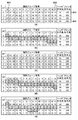
ヘッダ情報の符号長hd_size(=48ビット)と、全画素グループの符号長との合計を加算したブロック符号長bl_size[qp]の算出が行われる。図8(a)及び図8(c)は、pg_size[qp][pg]とbl_size[qp]の値の具体的な例を示す。図8(a)は図4(a)の正順入力に対応し、図8(c)は図4(b)の逆順入力に対応する。図8(c)では画素グループ番号が左から右へ15から0と降順となっているが、これは逆順を説明するためであって、図8(a)と同様に画素グループ番号は左から0から15が割り当てられるものである。図8(a)において、例えば参照番号801が示す値(30)はpg_size[0][0]であり、符号化ブロックにおける先頭の画素グループをQP=0で符号化した場合の符号長を示す。同様に、参照番号802が示す値(18)はpg_size[0][15]であり、符号化ブロックにおける最後の画素グループをQP=0で符号化した場合の符号長を示す。また、参照番号803が示す値(382)はbl_size[0]であり、QP=0で符号化した場合のブロック符号長を示し、参照番号804が示す値(293)はbl_size[3]であり、QP=3で符号化した場合のブロック符号長を示す。それぞれの値はビット単位で表されている。同図の値は以降の説明でも、具体的な値の例として用いて説明する。図8(c)についても同様である。
The block code length bl_size [qp] is calculated by adding the sum of the code length hd_size (= 48 bits) of the header information and the code lengths of all pixel groups. FIGS. 8A and 8C show specific examples of the values of pg_size [qp] [pg] and bl_size [qp]. FIG. 8A corresponds to the forward input in FIG. 4A, and FIG. 8C corresponds to the reverse input in FIG. 4B. In FIG. 8C, the pixel group numbers are in descending order from 15 to 0 from left to right, but this is for explaining the reverse order, and as in FIG. 0 to 15 are assigned. In FIG. 8A, for example, a value (30) indicated by
次に、S503においてQP決定部115は、bl_size[qp]の中から所定の目標符号量target_size以下で、かつ最大の値を有するブロック符号長をsel_sizeに選定し、この時のqpをsel_qpに選定する。S503における具体的な処理は、図6のフローチャートに示すとおりである。
Next, in S503, the
まずS601にて、QP決定部115はQPの値:qpを0に初期化する。次にS602にてQP決定部115は、現在選択されているQPにおける符号化ブロックの符号長:bl_size[qp]と目標符号量:target_sizeとを比較する。比較の結果、bl_size[qp]がtarget_size以下である場合(S602で「YES」)にはS603に移行し、bl_size[qp]がtarget_sizeより大きい場合(S602で「NO」)にはS605に移行する。
First, in S601, the
S603では、S602において判定対象となったbl_size[qp]を選択すべきブロック符号長sel_sizeに決定する。次いでS604では、bl_size[qp]のQPの値を符号化ブロックの暫定的なQPを表すsel_qpに決定し、処理を終了する。 In step S603, bl_size [qp] to be determined in step S602 is determined as the block code length sel_size to be selected. Next, in S604, the QP value of bl_size [qp] is determined to be sel_qp representing the provisional QP of the encoded block, and the process ends.
S605では、現在選択されているQPの値が最大値(MAX_QP)よりも小さいかどうかを判定し、最大値より小さい場合(S605で「YES」)はS606においてQPの値を1つ更新し、S602に戻って処理を継続する。現在のQPの値が最大値以上の場合(S605で「NO」)は処理を終了する。本実施形態におけるMAX_QPの値は3となる。なお、S605でNOと判定された場合、目標符号量より小さいブロック符号長が存在せず、QPを選択できないこととなる。しかし、実際には、画像データのビット数に基づき、QPの設定範囲及び目標符号量の値を予め調整することにより、QPの最小値から最大値の間で目標符号量を下回るブロック符号長が得られるように設計することができる。 In S605, it is determined whether or not the value of the currently selected QP is smaller than the maximum value (MAX_QP). If the value is smaller than the maximum value (“YES” in S605), one QP value is updated in S606, The process returns to step S602 and continues. If the current value of QP is equal to or greater than the maximum value ("NO" in S605), the process ends. The value of MAX_QP in the present embodiment is 3. If NO is determined in S605, there is no block code length smaller than the target code amount, and QP cannot be selected. However, in practice, by adjusting the setting range of the QP and the value of the target code amount in advance based on the number of bits of the image data, the block code length below the target code amount between the minimum value and the maximum value of the QP is reduced. It can be designed to be obtained.
このようにQP=0の初期値から1ずつ更新して、量子化ステップを1から2へ、2から4へと1段ずつ上げながら符号化ブロックの符号長を順に目標符号量と比較していく。そして、最初に目標符号量以下となった符号長に対応するQPの値を暫定的なQP値とすることができる。目標符号量target_sizeの具体的値については、本実施形態では例示的に360ビットとして説明する。この値は、符号化前の画像データの情報量が10ビット×3×16=480ビットであるので、その3/4に相当する。目標符号量の大きさは期待する圧縮率に応じて任意に設定することができる。図8(a)及び図8(c)に示す例では、QP:2のブロック符号長bl_size[2]である326(ビット)が目標符号量360ビットよりも小さく、sel_sizeとして選定される。またこのときのQPの値2がsel_qpに決定される。ここで、符号化ブロックの符号長にヘッダ情報の符号長を含めていない場合、目標符号量の値は360ビットからヘッダ情報の符号長を差し引いた値となる。上述の例ではヘッダの符号長は48ビットであったので、この場合の目標符号量は312ビットとなる。
As described above, the code length of the coded block is sequentially compared with the target code amount while updating the quantization step by one step from 1 to 2 and from 2 to 4 step by step from the initial value of QP = 0. Go. Then, the value of the QP corresponding to the code length that first becomes equal to or less than the target code amount can be used as the provisional QP value. In the present embodiment, a specific value of the target code amount target_size will be described as 360 bits by way of example. This value corresponds to 3/4 of the information amount of the image data before encoding is 10 bits × 3 × 16 = 480 bits. The size of the target code amount can be arbitrarily set according to the expected compression ratio. In the example shown in FIGS. 8A and 8C, 326 (bits), which is the block code length bl_size [2] of QP: 2, is smaller than the target code amount of 360 bits, and is selected as sel_size. Further, the
図5の説明に戻り、S504ではQP決定部115がS503で決定した符号化ブロックの暫定的なQPの値sel_qpに対し画素グループ単位の調整を行う。これにより、画素グループ単位の適用QP:pg_qp[pg]を決定することができる。S504におけるpg_qp[pg]を決定するための処理の詳細を、図7のフローチャートを参照して詳述する。
Returning to the description of FIG. 5, in S504, the
図7において、S701では、QP決定部115は画素グループ単位の適用QPであるpg_qp[pg]を、S503で決定されたQP:sel_qpで初期化する。このとき、pg_qp[0]〜pg_qp[15]までの全てがsel_qpの値に初期化される。図8(a)及び図8(c)の例では、QP=2が選択されたのでpg_qp[0]〜pg_qp[15]は全て2に初期化される。次にS702では、QP決定部115は現時点の符号化ブロックの符号長を表すパラメータnew_sizeを、S603で決定されたsel_sizeの値に初期化する。例えば図8(a)及び図8(c)の例では、sel_sizeはQPが2のときのブロック符号長326に決定されたので、S702ではnew_sizeの値は326に初期化される。ヘッダ符号長を考慮していない場合は、ブロック符号長は278となる。次にS703では、QP決定部115は現在選択されているQPを示すパラメータqpの値をS604で決定されたsel_qpの値で初期化する。例えば図8(a)及び図8(c)の例では、sel_qpは2に決定されたので、S703ではqpの値は2に初期化される。
In FIG. 7, in S701, the
次にS704では、QP決定部115は新たなQPを示すパラメータnew_qpの値を、qpより1を減じた値で初期化する。new_qpは、現在選択されているqpの値を1つ繰り下げた値を示す。さらにS705では、QP決定部115は処理対象の画素グループの番号を示すパラメータpgを初期化する。画素グループは0から15までの16グループがあるので、pg=0に初期化される。さらにS706、S707ではQP決定部115はminus_sizeをpg_size[qp][pg]に設定し、plus_sizeをpg_size[new_qp][pg]に設定する。ここで、minus_sizeとは、現在のqpの値に基づく選択画素グループの符号長を示し、plus_sizeは現在のqpから1減じたnew_qpの値に基づく選択画素グループの符号長を示す。例えば、pg=0でqp=2の場合を考えると、図8(a)に示す例では、minus_sizeは24となり、plus_sizeは27となる。図8(c)に示す例では、minus_sizeは16となり、plus_sizeは18となる。このminus_sizeと、plus_sizeとは、画素グループ単位にqpを1だけ変更した場合に想定される符号化ブロックのブロック符号長の変化量を計算するために用いられる。
Next, in S704, the
S708では、QP決定部115は画素グループ単位にqpを1だけ変更した場合のブロック符号長を示すパラメータtmp_sizeを、上記のnew_size、minus_size、plus_sizeから式3により求める。
tmp_size=new_size−minus_size+plus_size・・・式3
例えば、pg=0でqp=2の場合を考えると、図8(a)の例ではnew_size=326、minus_size=24、plus_size=27であるから、tmp_size=329となる。同様に図8(c)の例ではnew_size=326、minus_size=16、plus_size=18であるから、tmp_size=328となる。
In S708, the
tmp_size = new_size-minus_size
For example, considering the case where pg = 0 and qp = 2, in the example of FIG. 8A, tmp_size = 329 because new_size = 326, minus_size = 24, and plus_size = 27. Similarly, in the example of FIG. 8C, since new_size = 326, minus_size = 16, and plus_size = 18, tmp_size = 328.
次にS709にてQP決定部115は、S708で求めたqp変更後の符号長tmp_sizeが、目標符号量(target_size)以下かどうかを判定する。tmp_sizeの値が目標符号量を上回る場合(S709で「NO」)、S714に移行する。一方、tmp_sizeの値が目標符号量以下の場合(S709で「YES」)、S710に移行する。S710では、QP決定部115はnew_sizeの値をtmp_sizeの値で更新する。次いでS711においてQP決定部115は処理対象の画素グループの適用QP:pg_qp[pg]をnew_qpの値で更新する。その後のS712、S713の処理では処理対象となる画素グループを更新していく。具体的にS712では、QP決定部115は現在の処理対象の画素グループの番号pgが画素グループの番号の最大値(MAX_PG)より小さいか否かを判定する。MAX_PGの値は、本実施形態の場合15となる。ここで、pgが最大値より小さい場合(S712で「YES」)、S713に移行してQP決定部115はpgを1だけ更新して、S706に戻って新たな画素グループについて画素グループ単位の適用QP:pg_qp[pg]を決定する処理を行う。一方、pgが最大値に一致する場合(S713で「NO」)、S714に移行する。
Next, in S709, the
次にS714では、QP決定部115は現在のqpの値が0より大きいか否かを判定すると共に、sel_qpから現在のqpを引いた値がMAX_DIFFより小さいか否かを判定する。MAX_DIFFは、sel_qpからqpを下げることが可能な回数を規定している。MAX_DIFFはQPが取り得る範囲に応じて任意に決定でき、例えば2とすることができ、その場合にはsel_qpの値から2回まではqpの値を下げることができる。上記の例ではsel_qp=2であるから、qp=0となるまで処理を行うことができる。仮にsel_qp=3であった場合にはqp=1までは下げられるが、qp=0には下げられない。またMAX_DIFFを1または3としてもよい。このように回数を制限するのは、再帰的処理の実行時間を制限するためである。MAX_DIFFを設定することによりsel_qpに追加して適用QPに含めることが可能なQPの種類数を規定することができる。
Next, in S714, the
S714では、QP決定部115はqpが0であった場合、または、qpを下げた回数がMAX_DIFFに一致する場合(S714で「NO」)は本処理を終了する。qpが0より大きく、かつ、qpを下げた回数がMAX_DIFFに満たない場合(S714で「YES」)は、S715に移行する。S715ではQP決定部115はqpの値を1だけ減じて、S704に戻って処理を繰り返す。このようにして決定された適用QPはQP決定部115から本符号化系120へ出力される。
In S714, when qp is 0 or when the number of times qp is reduced matches MAX_DIFF (“NO” in S714), the
ここで、図7における処理の具体例を、図4(a)の正順入力の場合につき図8(a)を参照して説明する。選定されたsel_size(図8(a)の例では326)を基にして、まず、画素グループ番号0の画素グループのQPの値を1だけ小さくした場合のブロック符号長(326−24−27=329)を算出し、目標符号量(360)と比較する。算出したブロック符号長が目標符号量以下であった場合、次の画素グループ番号1のQPを1だけ小さくした場合のブロック符号長を算出して、同じように目標符号量と比較する。このとき算出される画素グループ番号1のブロック符号長は(329−24+27=332)であり、目標符号量よりも小さい。このようにして画素グループを順に選択してブロック符号長を算出していくと以下のようになる。
Here, a specific example of the process in FIG. 7 will be described with reference to FIG. 8A for the case of the forward input in FIG. First, based on the selected sel_size (326 in the example of FIG. 8A), first, the block code length (326-24-27 = 326) when the QP value of the pixel group with the
画素グループ番号2:332−24+27=335
画素グループ番号3:335−18+22=339
画素グループ番号4:339−19+23=343
画素グループ番号5:343−15+18=346
画素グループ番号6:346−13+15=348
画素グループ番号7:348−13+15=350
画素グループ番号8:350−16+16=350
画素グループ番号9:350−18+22=354
画素グループ番号10:354−17+17=354
画素グループ番号11:354−15+18=357
画素グループ番号12:357−12+12=357
画素グループ番号13:357−16+20=361
Pixel group number 2: 332-24 + 27 = 335
Pixel group number 3: 335-18 + 22 = 339
Pixel group number 4: 339-19 + 23 = 343
Pixel group number 5: 343-15 + 18 = 346
Pixel group number 6: 346-13 + 15 = 348
Pixel group number 7: 348-13 + 15 = 350
Pixel group number 8: 350−16 + 16 = 350
Pixel group number 9: 350−18 + 22 = 354
Pixel group number 10: 354-17 + 17 = 354
Pixel group number 11: 354-15 + 18 = 357
Pixel group number 12: 357−12 + 12 = 357
Pixel group number 13: 357-16 + 20 = 361
上記算出されたブロック符号長において、画素グループ番号13のブロック符号長は目標符号量を超えてしまう。よって、これ以降は再び画素グループ番号0に戻ってQPの値を更に1だけ減少させて、同じようにブロック符号長を算出していく。但し、MAX_DIFF=1であった場合にはこの時点で処理を終了する。
画素グループ番号0:357−27+30=360
画素グループ番号1:360−27+30=363
In the calculated block code length, the block code length of the
Pixel group number 0: 357-27 + 30 = 360
Pixel group number 1: 360−27 + 30 = 363
ここでは画素グループ番号1において目標符号量を超えてしまう。この時点でqpの値は0となっているので処理を終了する。このようにして決定された適用QPの具体的な値を図8(b)に示す。図8(b)では、太線で囲った符号長に対応するQPが、画素グループ毎に決定された適用QPを表している。画素グループ単位の適用QPの各値は、pg_qp[0]は0、pg_qp[1〜12]は1、pg_qp[13〜15]は2となる。このように、本実施形態では、先頭の画素グループから順により小さいQPが割り当てられる。図8(b)では先頭の画素グループのみにQP=0が割り当てられたが、他の条件では先頭の画素グループを含む連続する複数の画素グループに対して最小のQPを割り当てることも可能である。
Here, the
次に、図7における処理の具体例を、図4(b)の逆順入力の場合につき図8(c)を参照して説明する。選定されたsel_size(図8(c)の例では326)を基にして、まず、画素グループ番号0(スキャン変換前の正順では15、以下同様)の画素グループのQPの値を1だけ小さくした場合のブロック符号長(326−16+18=328)を算出し、目標符号量(360)と比較する。算出したブロック符号長が目標符号量以下であった場合、次の画素グループ番号1(14)のQPを1だけ小さくした場合のブロック符号長を算出して、同じように目標符号量と比較する。このとき算出される画素グループ番号1のブロック符号長は(328−18+18=328)であり、目標符号量よりも小さい。このようにして画素グループを順に選択してブロック符号長を算出していくと以下のようになる。
Next, a specific example of the processing in FIG. 7 will be described with reference to FIG. 8C for the case of the reverse input in FIG. 4B. First, based on the selected sel_size (326 in the example of FIG. 8C), the QP value of the pixel group of the pixel group number 0 (15 in the normal order before scan conversion, and so on) is reduced by one. Then, the block code length (326-16 + 18 = 328) is calculated and compared with the target code amount (360). If the calculated block code length is equal to or smaller than the target code amount, the block code length when the QP of the next pixel group number 1 (14) is reduced by 1 is calculated and similarly compared with the target code amount. . The block code length of the
画素グループ番号2(13):328−16+20=332
画素グループ番号3(12):332−12+12=332
画素グループ番号4(11):332−15+18=335
画素グループ番号5(10):335−17+17=335
画素グループ番号6(9):335−18+22=339
画素グループ番号7(8):339−16+16=339
画素グループ番号8(7):339−13+15=341
画素グループ番号9(6):341−13+15=343
画素グループ番号10(5):343−15+18=346
画素グループ番号11(4):346−19+23=350
画素グループ番号12(3):350−18+22=354
画素グループ番号13(2):354−24+27=357
画素グループ番号14(1):357−24+27=360
画素グループ番号15(0):360−24+27=363
Pixel group number 2 (13): 328-16 + 20 = 332
Pixel group number 3 (12): 332-12 + 12 = 332
Pixel group number 4 (11): 332-15 + 18 = 335
Pixel group number 5 (10): 335-17 + 17 = 335
Pixel group number 6 (9): 335-18 + 22 = 339
Pixel group number 7 (8): 339-16 + 16 = 339
Pixel group number 8 (7): 339-13 + 15 = 341
Pixel group number 9 (6): 341-13 + 15 = 343
Pixel group number 10 (5): 343-15 + 18 = 346
Pixel group number 11 (4): 346-19 + 23 = 350
Pixel group number 12 (3): 350−18 + 22 = 354
Pixel group number 13 (2): 354-24 + 27 = 357
Pixel group number 14 (1): 357-24 + 27 = 360
Pixel group number 15 (0): 360−24 + 27 = 363
上記算出されたブロック符号長において、画素グループ番号15(0)のブロック符号長は目標符号量を超えてしまう。よって、これ以降は再び画素グループ番号0に戻ってQPの値を更に1だけ減少させて、同じようにブロック符号長を算出していく。但し、MAX_DIFF=1であった場合にはこの時点で処理を終了する。
画素グループ番号0(15):360−18+18=360
画素グループ番号1(14):360−18+18=360
画素グループ番号2(13):360−20+20=360
画素グループ番号3(12):360−12+12=360
画素グループ番号4(11):360−18+22=364
In the calculated block code length, the block code length of the pixel group number 15 (0) exceeds the target code amount. Therefore, thereafter, the process returns to the
Pixel group number 0 (15): 360−18 + 18 = 360
Pixel group number 1 (14): 360−18 + 18 = 360
Pixel group number 2 (13): 360−20 + 20 = 360
Pixel group number 3 (12): 360−12 + 12 = 360
Pixel group number 4 (11): 360−18 + 22 = 364
ここでは画素グループ番号4(11)において目標符号量を超えてしまう。この時点でqpの値は0となっているので処理を終了する。このようにして決定された適用QPの具体的な値を図8(d)に示す。図8(d)では、太線で囲った符号長に対応するQPが、画素グループ毎に決定された適用QPを表している。画素グループ単位の適用QPの各値は、pg_qp[0〜3(15〜12)]は0、pg_qp[4〜14(11〜1)]は1、pg_qp[15(0)]は2となる。以上の例では、ヘッダ情報の符号長を考慮した場合について説明したが、ヘッダ情報の符号長を考慮しない場合には上述の数値からヘッダ情報の符号長48ビットを適宜差し引くだけでよい。 Here, the target code amount is exceeded in the pixel group number 4 (11). At this point, the value of qp has become 0, and the process is terminated. FIG. 8D shows a specific value of the applied QP determined in this way. In FIG. 8D, QPs corresponding to code lengths surrounded by thick lines represent applied QPs determined for each pixel group. Each value of the applied QP for each pixel group is 0 for pg_qp [0-3 (15-12)], 1 for pg_qp [4-14 (11-1)], and 2 for pg_qp [15 (0)]. . In the above example, the case where the code length of the header information is considered has been described. However, when the code length of the header information is not considered, it is only necessary to appropriately subtract the code length of 48 bits of the header information from the above numerical value.
以上、説明したように、本実施形態では、QP決定部115におけるS504の画素グループ単位の適用QPの決定方法において、ブロックの総符号量が目標符号量を超えない範囲で、先頭の画素グループから順にQPを小さい値に変更することができる。また、本実施形態では、仮符号化系及び本符号化系に入力される画像データは予め各ラインの奇数番のブロックと偶数番目のブロックとでスキャン順を逆にしている。
As described above, according to the present embodiment, in the method of determining the applied QP for each pixel group in S504 in the
図9(a)は仮符号化系110、本符号化系120における処理順を示す模式図である。図9(a)において画像データ901は、複数の符号化ブロック902及び903で構成される。符号化ブロック902は奇数番目の符号化ブロックを示し、符号化ブロック903は偶数番目の符号化ブロックを示す。各符号化ブロック中の矢印は符号化の処理順を表している。ここでは奇数番目のブロック902は左から右に符号化処理が行われ、偶数番目のブロック903は右から左に逆順に符号化処理が行われることになる。
FIG. 9A is a schematic diagram showing the processing order in the
このように処理順をブロック毎に交互に変えることによって、ブロック内のQP値の変化する方向がブロック毎に交互に変化する。本実施形態におけるQP値の変化する方向はブロックの処理順に先頭ブロック側に小さいQPが選ばれるため、各ブロック内では小から大のQP値の変化となっている。これが処理対象の画素順をブロック毎に交互に変えることによって、例えば奇数番のブロックは小から大のQP値の変化となり、偶数番のブロックは大から小のQP値の変化となる。このQPの変化の一例を図9(b)に示す。 In this way, by changing the processing order alternately for each block, the direction in which the QP value in the block changes alternately changes for each block. In the direction in which the QP value changes in the present embodiment, a small QP value is selected on the head block side in the processing order of the blocks, so that the QP value changes from small to large in each block. This changes the order of pixels to be processed alternately for each block, so that, for example, odd-numbered blocks change from small to large QP values, and even-numbered blocks change from large to small QP values. FIG. 9B shows an example of this change in QP.
図9(b)はブロック内のQP値の一例を示す模式図である。同図においても、画像データ901は複数の符号化ブロック902及び903で構成される。奇数番目のブロック902はスキャン変換されずに符号化されるため、無地で示す前半画素グループ911は第1のQP値(例えば2)で符号化され、斜線で示す後半画素グループ912は第2のQP値(例えば3)で符号化される。同様にして偶数番目のブロック903は、スキャン変換されて逆順に符号化されるため、斜線で示す前半画素グループ913が第2のQP値で符号化され、無地で示す後半画素グループ914が第1のQP値で符号化される。他のブロックにおいても同様にして第1のQP値を無地、第2のQP値を斜線でそれぞれ示している。自然画においては隣接するブロックは同じような絵柄となる場合が多く、同じQP値となる場合が多いためこのようなQP値の分布は有効である。
このように処理順をブロック毎に交互に変えることによって、隣接するブロックの境界部分のQP値の差を小さくし、ブロック境界部分の画質が一様となる。これにより、ブロック境界部分の劣化により不自然にブロック境界が視認されるようなことを低減することができる。
FIG. 9B is a schematic diagram illustrating an example of a QP value in a block. Also in the figure, the
By alternately changing the processing order for each block in this manner, the difference in QP value at the boundary between adjacent blocks is reduced, and the image quality at the block boundary becomes uniform. Thereby, it is possible to reduce the possibility that the block boundary is visually recognized due to the deterioration of the block boundary portion.
また本実施形態では、ブロック符号量が所定値を超えない範囲でQPを高画質となる方向に調整して未使用のビットを可能な限り削減しつつ、符号化結果の品質を向上させることができる。量子化ステップが小さいQPの使用割合が増え、未使用のビット数を削減できるため、符号化による画質劣化をさらに低減できる。 Further, in the present embodiment, it is possible to improve the quality of the coding result while reducing unused bits as much as possible by adjusting the QP in the direction of high image quality within a range where the block code amount does not exceed a predetermined value. it can. Since the use ratio of the QP having a small quantization step is increased and the number of unused bits can be reduced, image quality deterioration due to encoding can be further reduced.
(本符号化系の説明)
次に、図1の本符号化系120の動作について説明する。本符号化系120にも仮符号化系110に入力された画像データと同一の画像データが入力されるが、仮符号化系110のQP決定部115が適用QPを決定し出力するまで待機する必要がある。そこで、入力画像データは遅延部121に入力され、仮符号化系110が適用QPを決定するために必要な所定の処理サイクル分だけ遅延される。遅延後の画像データは遅延部121から符号化部111Eへ出力される。これにより符号化部111Eは、仮符号化系110が適用QPを決定した符号化ブロックを、当該決定された適用QPを用いて符号化することができる。
(Description of the present encoding system)
Next, the operation of the
符号化部111Eは、図3に示した符号化部111と同一の構成を有し、適用QPを用いて、遅延された画像データを本符号化する。これによりQP決定部115が決定したブロック符号長と同じ符号長の符号データが生成され、PCM/DPCM選択フラグ、符号長と共に多重化部123に出力される。多重化部123には符号化部111Eからの符号データ、符号長、PCM/DPCM選択フラグと、QP決定部115からのQPが入力されており、符号ブロック毎に所定のフォーマットで多重化が行われる。
以下、発明の実施形態に対応するフォーマットの一例について図10(a)を用いて説明する。図10(a)は符号化フォーマットのデータ構造を表す図であり、括弧で示す数値は各領域に格納されるデータのビット数を表している。ブロックの全体の符号化データ1001(360ビット)は、ヘッダ部1002(48ビット)と、画素データ部1003(312ビット)から構成される。ヘッダ部1002はQPの値を格納するQP値部1004(32ビット)とPCM/DPCM選択フラグを格納するフラグ部1005(16ビット)とで構成される。QP値部1004には画素グループ毎に2ビットのQP(1004_0〜1004_fまで)が16個分格納される。フラグ部1005には画素グループ毎に1ビットのPCM/DPCM選択フラグのフラグ値(1005_0〜1505_fまで)が16個分格納される。画素データ部1003には符号データが画素数分(3×16=48画素分)格納される。多重化された符号化データ1001はストリームデータとして出力端子102に出力され、非図示の画像メモリ、バスインターフェースに出力される。
Hereinafter, an example of a format corresponding to the embodiment of the present invention will be described with reference to FIG. FIG. 10A is a diagram illustrating a data structure of an encoding format. Numeric values shown in parentheses indicate the number of bits of data stored in each area. Encoded data 1001 (360 bits) of the entire block includes a header section 1002 (48 bits) and a pixel data section 1003 (312 bits). The
(画像復号化部の説明)
次に、画像符号化部20で生成された符号化データを復号する、発明の実施形態に対応する画像復号化部の構成例及び動作について説明する。図2は、発明の実施形態に対応する画像復号化部40の構成例を示すブロック図である。画像処理装置100は画像復号化部40を有し、メモリ30に記憶された符号化データを復号することができる。以下、本実施形態の画像復号化部の構成例において各ブロックの動作について説明する。
(Description of image decoding unit)
Next, a configuration example and operation of an image decoding unit corresponding to the embodiment of the present invention, which decodes the encoded data generated by the
図2に示す画像復号化部40は、分離部203、可変長復号化部204、加算器205、セレクタ206、逆量子化部207、予測部208で構成されている。画像復号化部40は、専用のデバイス、ロジック回路やメモリを用いてハードウェア的に一体的に構成されても良いし、或いは、複数のデバイス等で分散して構成されてもよい。或いは、メモリに記憶されている処理プログラムをCPU等のコンピュータが実行することにより、ソフトウェア的に構成されてもよい。
The
画像復号化部40には、非図示の画像メモリ、バスインターフェースなどを介して、画像符号化部20で生成されたストリームデータが入力端子201を介して分離部203に入力される。分離部203は入力されたストリームデータを所定のフォーマットに従ってデコードして、QP、PCM/DPCM選択フラグ、符号データの情報を分離し、処理サイクル毎に順次出力する。QPは逆量子化部207と量子化部210に出力し、PCM/DPCM選択フラグはセレクタ206に出力する。符号データのうち、PCMデータはセレクタ206に出力し、DPCMデータは可変長復号化部204に出力する。可変長復号化部204は入力されたDPCMデータの可変長復号化を行い、復号化されたDPCMデータを加算器205に出力する。加算器205は、後述の予測部208からの予測値と復号されたDPCMデータを加算して復号値を得て、セレクタ206に出力する。
The stream data generated by the
セレクタ206は分離部203からのPCMデータと、加算器205からの復号値を、PCM/DPCM選択フラグに応じて切り替えて量子化データとして出力し、逆量子化部207へ出力する。逆量子化部207はQP値を用いて、セレクタ206からの量子化データを逆量子化して、復号画像データを生成し、予測部208と出力端子202に出力する。予測部208は画素遅延部209、量子化部210から構成される。逆量子化部207から入力された復号画像データは、画素遅延部209にて同じカラー要素の前値が予測値となるようカラー要素分遅延され、量子化部210にて量子化されて予測値として出力される。なお、各カラー要素の符号化ブロックの最初の画素は前画素が存在しないため、予測値としては0の値を出力する。逆量子化部207から出力された復号画像データは出力端子202を介し、スキャン変換部211を介してスキャン変換された後に外部へと出力される。
The
スキャン変換部211はブロック毎に画像データを一旦保持し、各ラインの偶数番目のブロックはスキャン順を逆にして逆順で出力し、奇数番目のブロックは画素のスキャン順を変えずに出力する。スキャン順を逆にして出力するとは、スキャン変換部130との関連で説明した内容と同意である。これにより、画像符号化部20におけるスキャン変換部130でスキャン変換されたブロックのスキャン順が元に戻されて出力される。元のスキャン順に戻された復号画像データは出力端子202を介し、外部へと出力される。
The
以上説明したように、本実施形態では、複数の画素グループからなる符号化対象の符号化ブロック毎の固定長の符号化を行うため、まず、仮符号化系にて複数のQPで仮符号化して符号量を求め、それらの符号量から画素グループ単位に適用するQPの値を決定する。次いで本符号化系にて、決定された適用QPを用いて本符号化を行う構成とした。これにより、符号化ブロックのブロック符号長が所定値を超えない最大の値となるようにQPの値を決定することができる。また、画素グループ毎に符号長が所定値を超えない範囲でQPの値をより小さい値とすることができるので、画素グループ単位に画質を向上させることができる。また、画像符号化の処理順をブロック毎に交互に変えることによって、隣接するブロックの境界部分のQP値の差を小さくし、ブロック境界部分の画質が一様となる。これにより、ブロック境界部分の劣化により不自然にブロック境界が視認されるようなことを低減することができる。 As described above, in this embodiment, in order to perform fixed-length encoding for each encoding block to be encoded including a plurality of pixel groups, first, provisional encoding is performed by a plurality of QPs in a temporary encoding system. The amount of code is obtained by using the code amount, and the value of QP applied to each pixel group is determined from the code amount. Next, the main encoding system performs the main encoding using the determined applied QP. As a result, the value of QP can be determined so that the block code length of the coding block does not exceed a predetermined value. Further, since the value of QP can be set to a smaller value within a range in which the code length does not exceed the predetermined value for each pixel group, the image quality can be improved for each pixel group. Further, by alternately changing the processing order of the image coding for each block, the difference in QP value at the boundary between adjacent blocks is reduced, and the image quality at the block boundary becomes uniform. Thereby, it is possible to reduce the possibility that the block boundary is visually recognized due to the deterioration of the block boundary portion.
また、符号化の際に用いるQPおよびPCM/DPCM選択フラグは画素グループ単位で選択(切替)が可能な構成とした。PCM/DPCM選択は、隣接画素差分に応じて、差分が大きい場合はPCMとし、差分が小さい場合はDPCMにするのではなく、各画素グループでPCM、DPCMの両方の符号長を算出しておき、符号長がより小さくなる符号化方式を選択するようにした。これにより、ブロック単位での効率的な符号化が可能となる。 The QP and PCM / DPCM selection flags used in encoding can be selected (switched) in pixel group units. In the PCM / DPCM selection, the code length of both PCM and DPCM is calculated for each pixel group instead of PCM when the difference is large and DPCM when the difference is small, according to the difference between adjacent pixels. , An encoding method that makes the code length smaller is selected. This enables efficient coding in block units.
具体的に本実施形態では、隣接画素間の差分が大きくなる場合であっても特許文献1のようにPCM符号化の場合に符号長を10ビットから5ビットに強制的に半分にはしない。その代わり、量子化ステップ1を含む段階的に設定された複数の量子化ステップを用いて、PCM及びDPCMの各符号化結果において符号長の短いものを画素グループ毎に選択しておく。さらに、本実施形態ではグループ単位の符号長だけでなく、符号化ブロックのブロック符号長を考慮して量子化ステップを選択するため、一部の画素グループにおいて符号長が大きくなったとしても、他の画素グループの符号長が小さければそこで相殺される。よって、符号化ブロック内に急峻なエッジが含まれ、当該エッジ成分で大きな符号長が費やされたとしても、エッジの前後が平坦であれば当該エッジの符号長の分はそこで吸収されるので、エッジ成分を符号化する際に特許文献1のように不必要にビットを削減する必要がなくなる。
Specifically, in the present embodiment, even when the difference between adjacent pixels is large, the code length is not forcibly reduced from 10 bits to 5 bits in the case of PCM encoding as in
上述の発明の実施形態において、画像データのビット数は、10ビットに限定されるものではなく、8ビット、12ビットなど異なるビット数であってもよい。また、ブロックサイズは水平16画素×垂直1画に限定されるものではなく、任意のサイズでよい。例えば水平4画素×垂直4画素のように2次元構造としてもよい。 In the embodiment of the invention described above, the number of bits of the image data is not limited to 10 bits, but may be a different number of bits such as 8 bits or 12 bits. Further, the block size is not limited to 16 horizontal pixels × one vertical picture, but may be any size. For example, a two-dimensional structure such as 4 horizontal pixels × 4 vertical pixels may be used.
さらに、符号化対象の画像データの形式はRGB画像データに限定されるものではなく、グレースケール画像、カラー画像のうちYCbCr、ベイヤー配列データなどの画像データ形式であってもよい。図4(c)は画像データ形式が輝度信号(Y)と、二つの色差信号(Cr,b)であり、YCbCr4:2:2の場合の符号化ブロックを構成する画素データと、画素グループとの関係について示す。図4(c)では、Yを2画素、Cb、Crを1画素ずつの計4画素を単位画素グループとし、符号化ブロックを4×8=32画素から構成する例を示している。ここで、符号化ブロックに含める画素グループの数はより8グループよりも多くても良い。図4(d)は、画像データ形式がベイヤー配列の場合の符号化ブロックを構成する画素データと、画素グループとの関係について示す。図4(d)では、Gを2画素、R、Bを1画素ずつの計4画素を単位画素グループとし、符号化ブロックを4×8=32画素から構成する例を示している。ここで、符号化ブロックに含める画素グループの数はより8グループよりも多くても良い。グレースケール画像については不図示であるが、グレースケール画像を構成する画素のうち隣接画素の組から画素グループを構成することができる。その際、単位画素グループには例えば3画素または4画素の隣接画素を含めることができる。 Further, the format of the image data to be encoded is not limited to the RGB image data, but may be an image data format such as YCbCr or Bayer array data among gray scale images and color images. FIG. 4C shows a pixel data and a pixel group which form an encoding block in the case where the image data format is a luminance signal (Y) and two color difference signals (Cr, b), and is YCbCr 4: 2: 2. The relationship is shown below. FIG. 4 (c) shows an example in which a total of 4 pixels, Y for 2 pixels and Cb and Cr for 1 pixel, are taken as a unit pixel group, and the coding block is composed of 4 × 8 = 32 pixels. Here, the number of pixel groups included in the coding block may be more than eight. FIG. 4D illustrates a relationship between pixel data and a pixel group forming an encoding block when the image data format is the Bayer array. FIG. 4D shows an example in which a total of 4 pixels, G for 2 pixels and R and B for 1 pixel, are taken as a unit pixel group, and an encoding block is composed of 4 × 8 = 32 pixels. Here, the number of pixel groups included in the coding block may be more than eight. Although not shown, the grayscale image can form a pixel group from a set of adjacent pixels among the pixels forming the grayscale image. At this time, the unit pixel group can include, for example, three or four adjacent pixels.
[実施形態2]
次に、発明の他の実施形態を説明する。本実施形態2と上述の実施形態1との相違点は、画像符号化部20のQP決定部115内部の処理にあり、その他の符号化部、遅延部、多重化部の構成及び動作については実施形態1と同様であるため説明は省略する。
[Embodiment 2]
Next, another embodiment of the invention will be described. The difference between the second embodiment and the above-described first embodiment lies in the processing inside the
本施形態における、QP決定部115の処理手順の概要は図5及び図6に示したものと基本的に同じである。但し、本実施形態では、S504で画素グループ単位の適用QPを決定する方法が実施形態1とは異なる。本実施形態に対応する処理の詳細は図11のフローチャートに示す通りである。図11のフローチャートは図7のフローチャートの変形例であって、pg_num、sign、pg_updateという3つの新たなパラメータが追加され、これに伴って処理が一部異なっている。
The outline of the processing procedure of the
図11において、S1101からS1104までの処理はS701からS704までと同じである。S1105では、QP決定部115は処理対象の画素グループの番号を示すパラメータpgを0に初期化する。また、処理済みの画素グループ数を示すpg_numを0に初期化するとともに、pg更新方法を切替えるための符号signを0に初期化する。また、処理対象の画素グループを切替えるために使用するpg_updateを15に初期化する。
In FIG. 11, the processing from S1101 to S1104 is the same as the processing from S701 to S704. In step S1105, the
その後のS1106からS1111までの処理はS706からS711までの処理と同様である。続くS1112の処理では、QP決定部115は現在処理済みの画素グループ数を示すpg_numが画素グループの番号の最大値(MAX_PG)より小さいか否かを判定する。MAX_PGの値は、本実施形態の場合15となる。ここでpg_numが最大値より小さい場合(S1112で「YES」)、S1113に移行し、pg_numが最大値と一致する場合(S1112で「NO」)、S1117に移行する。S1113ではQP決定部115は符号signが0か否かを判定する。もし符号が0の場合は(S1113で「YES」)、S1114に移行し、符号が1の場合は(S1113で「NO」)、S1115に移行する。ここで符号signが0の値を有するとは、処理対象の画素グループがブロックの先頭により近いことを意味し、符号signが1の値を有するとは、処理対象の画素グループがブロックの最後尾により近いことを意味する。本実施形態では、処理対象の画素グループを先頭側と最後尾側とで交互に切替えていくことを特徴とするが、その切替のために符号signを用いている。
The subsequent processing from S1106 to S1111 is the same as the processing from S706 to S711. In the subsequent process of S1112, the
S1114では、処理対象の画素グループの番号を示すパラメータpgにpg_updateの値を加算してpgを更新し、S1116に移行する。例えば、処理対象の画素グループがpg=0だった場合、pg_updateは初期値として15を与えられているので、次の処理対象の画素グループpgは15となる。一方、S1115では、処理対象の画素グループの番号を示すパラメータpgからpg_updateの値を減算してpgを更新し、S1116に移行する。例えば、処理対象の画素グループがpg=15で、pg_updateが14であった場合、次の処理対象の画素グループpgは1となる。 In S1114, the value of pg_update is added to the parameter pg indicating the number of the pixel group to be processed, the pg is updated, and the flow shifts to S1116. For example, when the pixel group to be processed is pg = 0, pg_update is given 15 as an initial value, so that the next pixel group pg to be processed is 15. On the other hand, in S1115, pg is updated by subtracting the value of pg_update from the parameter pg indicating the number of the pixel group to be processed, and the flow shifts to S1116. For example, if the pixel group to be processed is pg = 15 and pg_update is 14, the next pixel group pg to be processed is 1.
S1116では、pg_updateを、現在の値から1を減算することにより更新する。例えば、pg_updateが15であれば、更新後のpg_updateは14である。また、符号signを、1から現在の値を減ずることにより更新する。この演算により、符号signは0と1とを交互に有することになる。さらにpg_numを、現在の値に1を加算することにより、処理済みの画素グループ数を更新する。その後、S1106に戻って処理を継続する。 In S1116, pg_update is updated by subtracting 1 from the current value. For example, if pg_update is 15, pg_update after update is 14. Also, the sign is updated by subtracting the current value from 1. By this operation, the sign has 0 and 1 alternately. Further, by adding 1 to pg_num and the current value, the number of processed pixel groups is updated. Thereafter, the process returns to S1106 to continue the process.
以上の処理において、処理対象の画素グループを示すpgは初期値0から始まり、S1114またはS1115の更新処理に従い順に15、1、14、2、13、3、12、4、11、5、10、6、9、7、8と切り替わり、ブロック符号長の算出はブロックの左右端の画素グループから徐々に中央の画素グループに向かって実施されることになる。こうして算出したブロック符号長が目標符号量を超えた場合(S1109で「NO」)、S1117に移行する。S1117及びS1118の処理は、S714及びS715の処理と同様である。
In the above processing, pg indicating the pixel group to be processed starts from the
ここで図11における処理の具体例を、図4(a)の入力の場合につき図8(e)を参照して説明する。選定されたsel_size(図8(e)の例では326)を基にして、まず、画素グループ番号0の画素グループのQPの値を1だけ小さくした場合のブロック符号長(326−24+27=329)を算出し、目標符号量(360)と比較する。算出したブロック符号長が目標符号量以下であった場合、次の画素グループ番号1のQPを1だけ小さくした場合のブロック符号長を算出して、同じように目標符号量と比較する。このとき算出される画素グループ番号15のブロック符号長は(329−16+18=331)であり、目標符号量よりも小さい。このようにして画素グループを順に選択してブロック符号長を算出していくと以下のようになる。
Here, a specific example of the processing in FIG. 11 will be described with reference to FIG. 8E for the case of the input in FIG. First, based on the selected sel_size (326 in the example of FIG. 8E), first, the block code length when the QP value of the pixel group with the
画素グループ番号1:331−24+27=334
画素グループ番号14:334−18+18=334
画素グループ番号2:334−24+27=337
画素グループ番号13:337−16+20=341
画素グループ番号3:341−18+22=345
画素グループ番号12:345−12+12=345
画素グループ番号4:345−19+23=349
画素グループ番号11:349−15+18=352
画素グループ番号5:352−15+18=355
画素グループ番号10:355−17+17=355
画素グループ番号6:355−13+15=357
画素グループ番号9:357−18+22=361
Pixel group number 1: 331-24 + 27 = 334
Pixel group number 14: 334-18 + 18 = 334
Pixel group number 2: 334-24 + 27 = 337
Pixel group number 13: 337-16 + 20 = 341
Pixel group number 3: 341-18 + 22 = 345
Pixel group number 12: 345-12 + 12 = 345
Pixel group number 4: 345-19 + 23 = 349
Pixel group number 11: 349−15 + 18 = 352
Pixel group number 5: 352-15 + 18 = 355
Pixel group number 10: 355-17 + 17 = 355
Pixel group number 6: 355-13 + 15 = 357
Pixel group number 9: 357-18 + 22 = 361
上記算出されたブロック符号長において、画素グループ番号9のブロック符号長は目標符号量を超えてしまう。よって、これ以降は再び画素グループ番号0に戻ってQPの値を更に1だけ減少させて、同じようにブロック符号長を算出していく。但し、MAX_DIFF=1であった場合にはこの時点で処理を終了する。
画素グループ番号0:357−27+30=360
画素グループ番号15:360−18+18=360
画素グループ番号1:360−27+30=363
In the calculated block code length, the block code length of the
Pixel group number 0: 357-27 + 30 = 360
Pixel group number 15: 360−18 + 18 = 360
Pixel group number 1: 360−27 + 30 = 363
ここでは画素グループ番号1において目標符号量を超えてしまう。この時点でqpの値は0となっているので処理を終了する。このようにして決定された適用QPの具体的な値を図8(e)に示す。図8(e)では、太線で囲った符号長に対応するQPが、画素グループ毎に決定された適用QPを表している。画素グループ単位の適用QPの各値は、pg_qp[0]は0、pg_qp[1〜6]は1、pg_qp[7〜9]は2、pg_qp[10〜14]は1、pg_qp[15]は0となる。
このように、本実施形態では、符号化ブロックの先頭または最後尾といった端部側に位置する画素グループにより小さいQPが割り当てられ、符号化ブロックの中心付近に位置する画素グループに大きいQPが割り当てられる。これによりブロック内のQP値はブロックの中央部が高く、ブロックの両端(すなわちブロック境界部分)が低く分布されるようになる。これにより、隣接するブロックの境界部分のQP値の差を小さくでき、ブロック境界部分の画質が一様となるため、ブロック境界が不自然に視認されることを少なくできる。
Here, the
As described above, in the present embodiment, a smaller QP is assigned to a pixel group located on the end side such as the beginning or end of an encoded block, and a larger QP is assigned to a pixel group located near the center of the encoded block. . As a result, the QP value in the block is distributed higher at the center of the block and lower at both ends of the block (that is, at the block boundary). This makes it possible to reduce the difference in QP value between the boundary portions of the adjacent blocks and to make the image quality of the block boundary portions uniform, thereby reducing the possibility of the block boundaries being viewed unnaturally.
[実施形態3]
次に、発明の更なる実施形態について説明する。本実施形態3と上述の実施形態1との相違点は多重化部123内部の処理方法であり、その他の符号化部、QP決定部、遅延部、多重化部の構成及び動作については実施形態1と同様であるため説明は省略する。
[Embodiment 3]
Next, a further embodiment of the invention will be described. The difference between the third embodiment and the above-described first embodiment is a processing method inside the
多重化部123には符号化部111Eからの符号データ、符号長、PCM/DPCM選択フラグと、QP決定部115からのQPが入力されており、符号ブロック毎に所定のフォーマットで多重化が行われる。ここで、QP決定部115からのQPは、実施形態1で図8(b)との関連で説明したように、
pg_qp[0]=0、
pg_qp[1〜12]=1
pg_qp[13〜15]=2
のように規則性がある。実施形態1では、図10(a)に示すとおり、QPを格納する領域1004を32ビット分用意した。しかし、実施形態3の例では全てのQPを格納しなくても、先頭(画素グループ番号:0)のQPと、QPが切り替る位置を示す画素グループ番号の情報があれば符号化ブロックにおけるQPの配列パターンを復元することができる。そこで、先頭のQPをqp0、QPが1番目に変化する画素グループ番号をqp_pos1、QPが2番目に変化する画素グループ番号をqp_pos2としてヘッダに格納する。このようなフォーマットによりヘッダ符号長の削減が可能になる。
The
pg_qp [0] = 0,
pg_qp [1-12] = 1
pg_qp [13 to 15] = 2
There is a regular like. In the first embodiment, as shown in FIG. 10A, an
また、上記では格納すべきQP値として先頭のQP、即ち最小のQPとしたが、同様の効果は割り当てられた最大のQPとした場合でも得られる。この場合でも切り替わり位置が特定できれば正しいQPの割当てを再現することができるからである。 In the above description, the QP value to be stored is the top QP, that is, the minimum QP, but the same effect can be obtained even when the assigned maximum QP is used. Even in this case, if the switching position can be specified, the correct QP assignment can be reproduced.
本実施形態に対応するヘッダフォーマットの一例を図10(b)を用いて説明する。図10(b)は符号化フォーマットのデータ構造の一例を示す図であり、ブロックの全体の符号化データ1011(360ビット)は、ヘッダ部1012(26ビット)と、画素データ部1013(334ビット)から構成される。ヘッダ部1012はQPを格納するQP値部1014(10ビット)とPCM/DPCM選択フラグを格納するフラグ部1015(16ビット)とで構成される。QP値部1014にはqp0の2ビット(1016)、qp_pos1の4ビット(1017)、qp_pos2の4ビット(1018)が格納される。図8(b)の例では、(0、1、13)の値が格納される。フラグ部1015には画素グループ毎に1ビットのPCM/DPCM選択フラグのフラグ値(1015_0〜1015_f)が16個分格納される。画素データ部1013には可変長符号である符号データが画素数分(3×16=48画素分)格納される。多重化された符号化データ1011はストリームデータとして出力端子102に出力され、非図示の画像メモリ、バスインターフェースに出力される。
An example of a header format corresponding to the present embodiment will be described with reference to FIG. FIG. 10B is a diagram showing an example of the data structure of the encoding format. The encoded data 1011 (360 bits) of the entire block includes a header section 1012 (26 bits) and a pixel data section 1013 (334 bits). ). The
図10(b)に示すヘッダフォーマットでは、ヘッダ符号長が26ビットで画像データ部の符号長が334ビットとなるため、上述の実施形態におけるブロック符号長の算出方法及び目標符号量の値が異なる。具体的に図5のS502におけるブロック符号長bl_size[qp]の算出においては、ヘッダ符号長を考慮する場合には、その大きさを26ビットとする。ブロック符号長の算出にヘッダ符号長を考慮しない場合、S503の目標符号量を334ビットとする。 In the header format shown in FIG. 10B, since the header code length is 26 bits and the code length of the image data portion is 334 bits, the calculation method of the block code length and the value of the target code amount in the above-described embodiment are different. . Specifically, in the calculation of the block code length bl_size [qp] in S502 in FIG. 5, when the header code length is taken into consideration, the size is set to 26 bits. When the header code length is not considered in the calculation of the block code length, the target code amount in S503 is set to 334 bits.
図10(b)では、ヘッダ部にQPの切り替わり位置の情報を2つ持たせる場合を説明したが、ヘッダ部に含めるべき切り替わり位置の情報の数は、図7のS714における判定で使用したMAX_DIFFの値に依存する。図10(b)はMAX_DIFF=2の場合を示したが、MAX_DIFF=1の場合は切り替わりの位置の情報としてqp_pos1の4ビットだけあれば足りるので、ヘッダ部1012のサイズを更に4ビット削減し、画素データ部1013のサイズを更に4ビット増加することができる。
FIG. 10B illustrates the case where the header section has two pieces of QP switching position information. However, the number of pieces of switching position information to be included in the header section is determined by MAX_DIFF used in the determination in S714 of FIG. Depends on the value of FIG. 10B shows the case of MAX_DIFF = 2, but in the case of MAX_DIFF = 1, only 4 bits of qp_pos1 are required as the information of the switching position, so the size of the
以上、説明したように、本実施形態においては多重化部123でQPをヘッダに格納する際に、QPの値をそのままヘッダに格納するのではなく、QPの初期値と、QPが切り替る位置の情報とを格納する。これにより、ヘッダ部の符号長を削減し、符号化データに含める画素データのサイズを増加させることができる。この結果、量子化ステップの小さいQPの使用割合が増えるため、符号化による画質劣化をさらに低減できる。
As described above, in the present embodiment, when the
(その他の実施例)
本発明は、上述の実施形態の1以上の機能を実現するプログラムを、ネットワーク又は記憶媒体を介してシステム又は装置に供給し、そのシステム又は装置のコンピュータにおける1つ以上のプロセッサーがプログラムを読出し実行する処理でも実現可能である。また、1以上の機能を実現する回路(例えば、ASIC)によっても実現可能である。
(Other Examples)
The present invention supplies a program for realizing one or more functions of the above-described embodiments to a system or an apparatus via a network or a storage medium, and one or more processors in a computer of the system or the apparatus read and execute the program. It can also be realized by the following processing. Further, it can be realized by a circuit (for example, an ASIC) that realizes one or more functions.
10:取得部、20:画像符号化部、30:メモリ、101:入力端子、102:出力端子、110:仮符号化系、120:本符号化系、スキャン変換部130
10: acquisition unit, 20: image encoding unit, 30: memory, 101: input terminal, 102: output terminal, 110: temporary encoding system, 120: main encoding system,
Claims (12)
前記符号化対象のブロックについて、該ブロックに含まれる前記グループごとに前記決定手段が決定した前記量子化ステップと前記符号化方式とに基づき前記符号化処理を行って符号化データを生成する符号化手段と
を備え、
前記決定手段は、
前記グループごとに、量子化された画像データを出力する第1の符号化方式と、量子化された画像データと予測データとの差分を符号化したデータを出力する第2の符号化方式とのうち、符号長がより小さくなる符号化方式に決定し、
複数の量子化ステップのうち、少なくとも第1の量子化ステップと第2の量子化ステップの何れかを前記グループごとに決定し、
前記第1の量子化ステップは、前記符号化対象のブロックに含まれる前記グループの全てについて該第1の量子化ステップを用いて量子化を行い、該グループのそれぞれについて前記決定された符号化方式で符号化した場合の前記符号化対象のブロックの符号長が前記所定値を超えず、且つ、最大の値となる量子化ステップであって、
前記第2の量子化ステップは、前記第1の量子化ステップよりも小さい量子化ステップであって、前記複数のグループのうち、少なくとも前記符号化対象のブロックの先頭のグループと最後尾のグループとに割り当てられることを特徴とする画像符号化装置。 In order to prevent the code length of an encoding target block including a plurality of groups each including a predetermined number of pixels from exceeding a predetermined value, for each of the groups, Determining means for determining a quantization step and a coding method,
Coding for generating the coded data by performing the coding process on the block to be coded based on the quantization step and the coding method determined by the determining unit for each of the groups included in the block. Means,
The determining means comprises:
For each of the groups, a first encoding method for outputting quantized image data and a second encoding method for outputting data obtained by encoding the difference between the quantized image data and the prediction data Of these, the coding length is decided to be smaller,
At least one of the first quantization step and the second quantization step among the plurality of quantization steps is determined for each of the groups,
The first quantization step performs quantization using the first quantization step for all of the groups included in the block to be encoded, and determines the determined encoding scheme for each of the groups. In the quantization step, the code length of the block to be encoded does not exceed the predetermined value, and is the maximum value,
The second quantization step is a quantization step smaller than the first quantization step, and among the plurality of groups, at least a first group and a last group of the block to be encoded. An image encoding device, wherein the image encoding device is assigned to
前記符号化対象のブロックの先頭のグループには、前記複数の異なる量子化ステップのうち最小の量子化ステップが割り当てられることを特徴とする、請求項1または2に記載の画像符号化装置。 The second quantization step includes a plurality of different quantization steps,
The group head of the block of the encoding target, characterized in that the minimum quantization step of said plurality of different quantization step is assigned, the image coding apparatus according to claim 1 or 2.
前記一部のグループは、
前記一部のグループのそれぞれを前記第2の量子化ステップを用いて量子化し、該一部のグループのそれぞれについて前記決定された符号化方式で符号化した場合の符号長の第1の合計と、
前記残りのグループのそれぞれを前記第1の量子化ステップを用いて量子化し、該残りのグループのそれぞれについて前記決定された符号化方式で符号化した場合の符号長の第2の合計と
の合計が、前記所定値を超えず、且つ、最大の値となるように決定されることを特徴とする、請求項1乃至6のいずれか1項に記載の画像符号化装置。 The determining means assigns the second quantization step to some of the plurality of groups, and assigns the first quantization step to the remaining groups of the plurality of groups;
The some groups are:
A first sum of code lengths when each of the some groups is quantized using the second quantization step, and each of the some groups is encoded using the determined coding scheme; ,
Sum of each of the remaining groups with the second sum of code lengths when quantized using the first quantization step and coded with the determined coding scheme for each of the remaining groups The image encoding apparatus according to any one of claims 1 to 6 , wherein is determined so as not to exceed the predetermined value and to have a maximum value.
前記取得手段が取得した前記画像データを符号化処理する請求項1乃至10のいずれか1項に記載の画像符号化装置と
を備えることを特徴とする画像処理装置。 Acquisition means for acquiring image data ;
The image processing apparatus characterized by comprising an image coding apparatus according to any one of claims 1 to 10 encoding processing the image data acquired by the acquisition unit.
前記画像符号化装置の決定手段が、それぞれが所定数の画素からなる複数のグループを含む符号化対象のブロックの符号長が所定値を超えないように、前記グループごとに、前記グループの画像データの符号化処理における量子化のための量子化ステップと符号化方式とを決定する決定工程と、
前記画像符号化装置の符号化手段が、前記符号化対象のブロックについて、該ブロックに含まれる前記グループごとに前記決定工程で決定された前記量子化ステップと前記符号化方式とに基づき前記符号化処理を行って符号化データを生成する符号化工程と
を含み、
前記決定工程では、
前記グループごとに、量子化された画像データを出力する第1の符号化方式と、量子化された画像データと予測データとの差分を符号化したデータを出力する第2の符号化方式とのうち、符号長がより小さくなる符号化方式に決定され、
複数の量子化ステップのうち、少なくとも第1の量子化ステップと第2の量子化ステップの何れかを前記グループごとに決定され、
前記第1の量子化ステップは、前記符号化対象のブロックに含まれる前記グループの全てについて該第1の量子化ステップを用いて量子化を行い、該グループのそれぞれについて前記決定された符号化方式で符号化した場合の前記符号化対象のブロックの符号長が前記所定値を超えず、且つ、最大の値となる量子化ステップであって、
前記第2の量子化ステップは、前記第1の量子化ステップよりも小さい量子化ステップであって、前記複数のグループのうち、少なくとも前記符号化対象のブロックの先頭のグループと最後尾のグループとに割り当てられることを特徴とする画像符号化方法。 An image encoding method executed by an image encoding device,
The determining means of the image coding apparatus determines, for each group, the image data of the group so that the code length of a block to be coded including a plurality of groups each including a predetermined number of pixels does not exceed a predetermined value. A determination step of determining a quantization step and an encoding method for quantization in the encoding process,
The encoding unit of the image encoding device performs the encoding on the encoding target block based on the quantization step and the encoding scheme determined in the determination step for each of the groups included in the block. Encoding step of performing processing to generate encoded data,
In the determining step,
For each of the groups, a first encoding method for outputting quantized image data and a second encoding method for outputting data obtained by encoding the difference between the quantized image data and the prediction data Out of which, the code length is determined to be smaller,
At least one of the first quantization step and the second quantization step among the plurality of quantization steps is determined for each of the groups,
The first quantization step performs quantization using the first quantization step for all of the groups included in the block to be encoded, and determines the determined encoding scheme for each of the groups. In the quantization step, the code length of the block to be encoded does not exceed the predetermined value, and is the maximum value,
The second quantization step is a quantization step smaller than the first quantization step, and among the plurality of groups, at least a first group and a last group of the block to be encoded. An image encoding method characterized in that the image encoding method is assigned to
Priority Applications (2)
| Application Number | Priority Date | Filing Date | Title |
|---|---|---|---|
| JP2015177919A JP6626295B2 (en) | 2015-09-09 | 2015-09-09 | Image encoding device, image processing device, image encoding method |
| US15/259,318 US9872042B2 (en) | 2015-09-09 | 2016-09-08 | Image encoding apparatus and image encoding method |
Applications Claiming Priority (1)
| Application Number | Priority Date | Filing Date | Title |
|---|---|---|---|
| JP2015177919A JP6626295B2 (en) | 2015-09-09 | 2015-09-09 | Image encoding device, image processing device, image encoding method |
Publications (3)
| Publication Number | Publication Date |
|---|---|
| JP2017055267A JP2017055267A (en) | 2017-03-16 |
| JP2017055267A5 JP2017055267A5 (en) | 2018-10-25 |
| JP6626295B2 true JP6626295B2 (en) | 2019-12-25 |
Family
ID=58190839
Family Applications (1)
| Application Number | Title | Priority Date | Filing Date |
|---|---|---|---|
| JP2015177919A Expired - Fee Related JP6626295B2 (en) | 2015-09-09 | 2015-09-09 | Image encoding device, image processing device, image encoding method |
Country Status (2)
| Country | Link |
|---|---|
| US (1) | US9872042B2 (en) |
| JP (1) | JP6626295B2 (en) |
Families Citing this family (16)
| Publication number | Priority date | Publication date | Assignee | Title |
|---|---|---|---|---|
| JP2014519741A (en) * | 2011-05-11 | 2014-08-14 | ペリカン イメージング コーポレイション | System and method for transmitting and receiving array camera image data |
| EP3565259A4 (en) * | 2016-12-28 | 2019-11-06 | Panasonic Intellectual Property Corporation of America | Three-dimensional model distribution method, three-dimensional model receiving method, three-dimensional model distribution device, and three-dimensional model receiving device |
| CN109788290A (en) * | 2017-11-13 | 2019-05-21 | 慧荣科技股份有限公司 | Image processor and the lossless image compressing method for utilizing intra prediction |
| US20220005233A1 (en) * | 2018-11-14 | 2022-01-06 | Nippon Telegraph And Telephone Corporation | Encoding apparatus, decoding apparatus, encoding system, learning method and program |
| KR102646521B1 (en) | 2019-09-17 | 2024-03-21 | 인트린식 이노베이션 엘엘씨 | Surface modeling system and method using polarization cue |
| MX2022004163A (en) | 2019-10-07 | 2022-07-19 | Boston Polarimetrics Inc | Systems and methods for surface normals sensing with polarization. |
| KR20230116068A (en) | 2019-11-30 | 2023-08-03 | 보스턴 폴라리메트릭스, 인크. | System and method for segmenting transparent objects using polarization signals |
| KR102330781B1 (en) * | 2020-01-17 | 2021-11-24 | 주식회사 와이젯 | Image processing method in wireless environment |
| JP7462769B2 (en) | 2020-01-29 | 2024-04-05 | イントリンジック イノベーション エルエルシー | System and method for characterizing an object pose detection and measurement system - Patents.com |
| KR20220133973A (en) | 2020-01-30 | 2022-10-05 | 인트린식 이노베이션 엘엘씨 | Systems and methods for synthesizing data to train statistical models for different imaging modalities, including polarized images |
| WO2021243088A1 (en) | 2020-05-27 | 2021-12-02 | Boston Polarimetrics, Inc. | Multi-aperture polarization optical systems using beam splitters |
| DE102021117397A1 (en) * | 2020-07-16 | 2022-01-20 | Samsung Electronics Co., Ltd. | IMAGE SENSOR MODULE, IMAGE PROCESSING SYSTEM AND IMAGE COMPRESSION METHOD |
| US20220020180A1 (en) * | 2020-07-16 | 2022-01-20 | Samsung Electronics Co., Ltd. | Image compression method using saturated pixel, encoder, and electronic device |
| US11290658B1 (en) | 2021-04-15 | 2022-03-29 | Boston Polarimetrics, Inc. | Systems and methods for camera exposure control |
| US11954886B2 (en) | 2021-04-15 | 2024-04-09 | Intrinsic Innovation Llc | Systems and methods for six-degree of freedom pose estimation of deformable objects |
| US11689813B2 (en) | 2021-07-01 | 2023-06-27 | Intrinsic Innovation Llc | Systems and methods for high dynamic range imaging using crossed polarizers |
Family Cites Families (13)
| Publication number | Priority date | Publication date | Assignee | Title |
|---|---|---|---|---|
| JPH05227520A (en) * | 1992-02-14 | 1993-09-03 | Hitachi Ltd | Picture compression-encoder |
| JP4042597B2 (en) * | 2002-03-28 | 2008-02-06 | ソニー株式会社 | Image encoding apparatus and method, program, and recording medium |
| KR100837410B1 (en) * | 2006-11-30 | 2008-06-12 | 삼성전자주식회사 | Method and apparatus for visually lossless image data compression |
| CN101816182B (en) | 2007-10-01 | 2012-11-21 | 夏普株式会社 | Image encoding device, image encoding method, and image encoding system |
| KR101664125B1 (en) * | 2009-09-22 | 2016-10-10 | 삼성전자주식회사 | System and method for image encoding capable of random access |
| JP2011259345A (en) * | 2010-06-11 | 2011-12-22 | Sharp Corp | Encoding device |
| JP5285682B2 (en) * | 2010-11-29 | 2013-09-11 | シャープ株式会社 | Image coding apparatus and image coding method |
| JP2014179707A (en) * | 2013-03-13 | 2014-09-25 | Toshiba Corp | Image encoder, and encoding method |
| JP2014179957A (en) * | 2013-03-15 | 2014-09-25 | Toshiba Corp | Image encoder and image decoder |
| GB2534409A (en) * | 2015-01-23 | 2016-07-27 | Sony Corp | Data encoding and decoding |
| JP6502739B2 (en) * | 2015-04-28 | 2019-04-17 | キヤノン株式会社 | Image coding apparatus, image processing apparatus, image coding method |
| JP6512928B2 (en) * | 2015-04-28 | 2019-05-15 | キヤノン株式会社 | Image coding apparatus, image processing apparatus, image coding method |
| JP6502753B2 (en) * | 2015-06-08 | 2019-04-17 | キヤノン株式会社 | Image coding apparatus, image processing apparatus, image coding method |
-
2015
- 2015-09-09 JP JP2015177919A patent/JP6626295B2/en not_active Expired - Fee Related
-
2016
- 2016-09-08 US US15/259,318 patent/US9872042B2/en not_active Expired - Fee Related
Also Published As
| Publication number | Publication date |
|---|---|
| JP2017055267A (en) | 2017-03-16 |
| US20170070753A1 (en) | 2017-03-09 |
| US9872042B2 (en) | 2018-01-16 |
Similar Documents
| Publication | Publication Date | Title |
|---|---|---|
| JP6626295B2 (en) | Image encoding device, image processing device, image encoding method | |
| JP6512928B2 (en) | Image coding apparatus, image processing apparatus, image coding method | |
| JP6502739B2 (en) | Image coding apparatus, image processing apparatus, image coding method | |
| JP6502753B2 (en) | Image coding apparatus, image processing apparatus, image coding method | |
| JPH09200758A (en) | Image encoder | |
| JP4833309B2 (en) | Video compression encoding device | |
| CN116918331A (en) | Coding method and coding device | |
| CN110087085B (en) | Image processing apparatus | |
| US11503296B2 (en) | Image processing apparatus, image processing method, and non-transitory computer-readable storage medium | |
| JP6985924B2 (en) | Image coding device, image processing device, image coding method | |
| JP6749725B2 (en) | Image coding apparatus, image processing apparatus, and image coding method | |
| JP7444541B2 (en) | Image encoding device, image decoding device, imaging device, image encoding method, image decoding method, and program | |
| JP7121584B2 (en) | Image encoding device and its control method and program | |
| JP2020092327A (en) | Image encoding device, image encoding method, and program | |
| JP3788895B2 (en) | Encoding apparatus, encoding method, and computer-readable recording medium recording a program for causing a computer to execute the encoding method | |
| TWI795480B (en) | Image processing device for performing data decompression and image processing device for performing data compression | |
| JP2009260747A (en) | Image encoding device, and control method thereof | |
| JP2023154574A (en) | Image processing apparatus and method for controlling the same and program | |
| JP4057610B2 (en) | Encoding / decoding system and encoding / decoding method | |
| JP4530421B2 (en) | Image encoding method, image decoding method, image encoding device, image decoding device, program thereof, and program recording medium thereof | |
| JP2009004878A (en) | Image processor, image processing method and image processing program, and imaging device | |
| JPH07298060A (en) | Image data coding method an device and image data decoding method and device | |
| JP2003274188A (en) | System for encoding still image | |
| JP2008228229A (en) | Image encoding apparatus and control method thereof |
Legal Events
| Date | Code | Title | Description |
|---|---|---|---|
| A521 | Request for written amendment filed |
Free format text: JAPANESE INTERMEDIATE CODE: A523 Effective date: 20180910 |
|
| A621 | Written request for application examination |
Free format text: JAPANESE INTERMEDIATE CODE: A621 Effective date: 20180910 |
|
| A977 | Report on retrieval |
Free format text: JAPANESE INTERMEDIATE CODE: A971007 Effective date: 20190412 |
|
| A131 | Notification of reasons for refusal |
Free format text: JAPANESE INTERMEDIATE CODE: A131 Effective date: 20190510 |
|
| A521 | Request for written amendment filed |
Free format text: JAPANESE INTERMEDIATE CODE: A523 Effective date: 20190619 |
|
| TRDD | Decision of grant or rejection written | ||
| A01 | Written decision to grant a patent or to grant a registration (utility model) |
Free format text: JAPANESE INTERMEDIATE CODE: A01 Effective date: 20191101 |
|
| A61 | First payment of annual fees (during grant procedure) |
Free format text: JAPANESE INTERMEDIATE CODE: A61 Effective date: 20191129 |
|
| R151 | Written notification of patent or utility model registration |
Ref document number: 6626295 Country of ref document: JP Free format text: JAPANESE INTERMEDIATE CODE: R151 |
|
| LAPS | Cancellation because of no payment of annual fees |