JP6625486B2 - Rehabilitation support control device and computer program - Google Patents
Rehabilitation support control device and computer program Download PDFInfo
- Publication number
- JP6625486B2 JP6625486B2 JP2016114890A JP2016114890A JP6625486B2 JP 6625486 B2 JP6625486 B2 JP 6625486B2 JP 2016114890 A JP2016114890 A JP 2016114890A JP 2016114890 A JP2016114890 A JP 2016114890A JP 6625486 B2 JP6625486 B2 JP 6625486B2
- Authority
- JP
- Japan
- Prior art keywords
- parameter
- display
- foot
- rehabilitation
- target
- Prior art date
- Legal status (The legal status is an assumption and is not a legal conclusion. Google has not performed a legal analysis and makes no representation as to the accuracy of the status listed.)
- Active
Links
Images


Description
本発明は、リハビリテーションを支援する技術に関する。 The present invention relates to a technique for supporting rehabilitation.
従来、タッチパネル上にリハビリテーション用の画像を表示し、画像に対応してリハビリテーションを受ける対象者が触れた位置を検出することによってリハビリテーションを評価する技術がある(例えば特許文献1参照)。 2. Description of the Related Art Conventionally, there is a technology for evaluating rehabilitation by displaying an image for rehabilitation on a touch panel and detecting a position touched by a subject who undergoes rehabilitation corresponding to the image (for example, see Patent Document 1).
一般的に、足を移動させるリハビリテーションは、リハビリテーションの対象者にとって単調で退屈な内容のものや対象者の状態にかかわらず一律に設定された内容のものが多い。そのため、対象者にとって足を移動させるリハビリテーションが苦痛となる場合があり、対象者が足を移動させるリハビリテーションをやめてしまう場合もある。 In general, rehabilitation in which the foot is moved is often monotonous and boring for the subject of rehabilitation, or one set uniformly regardless of the state of the subject. Therefore, rehabilitation in which the foot is moved may be painful for the subject, and rehabilitation in which the subject moves the foot may be stopped.
上記事情に鑑み、本発明は、足を移動させるリハビリテーションの対象者が能動的にリハビリテーションを行うことを支援することを可能とする技術の提供を目的としている。 In view of the above circumstances, an object of the present invention is to provide a technology that enables a subject of rehabilitation that moves a foot to actively support rehabilitation.
本発明の一態様は、足を移動させるリハビリテーションの対象者が足を移動させるときに足の移動先となるまたは足が触れてはならない所定の目標画像の表示に用いられる足用表示パラメータに基づいて、出力装置に前記目標画像を表示させる表示制御部を備えるリハビリテーション支援制御装置において、前記対象者の足の機能回復に伴い前記足用表示パラメータを変更可能とするリハビリテーション支援制御装置である。 One embodiment of the present invention is based on foot display parameters used for displaying a predetermined target image to which a foot is to be moved or a foot is not to be touched when a rehabilitation target person who moves the foot moves the foot. A rehabilitation support control device including a display control unit that causes the output device to display the target image, wherein the rehabilitation support control device enables the display parameter for the foot to be changed with the recovery of the function of the subject's foot.
本発明の一態様は、上記のリハビリテーション支援制御装置であって、前記表示制御部は、前記対象者の足の移動距離に係る前記足用表示パラメータである足用距離パラメータ、前記対象者の足の移動時間に係る前記足用表示パラメータである足用時間パラメータ、及び前記対象者の足の移動方向に係る前記足用表示パラメータである足用ベクトルパラメータ、のうちの少なくとも1つに基づいて、前記出力装置に前記目標画像を表示させる。 One embodiment of the present invention is the above-described rehabilitation support control device, wherein the display control unit is a foot distance parameter that is the foot display parameter related to a moving distance of the target person's foot; Based on at least one of the foot time parameter that is the foot display parameter related to the movement time of the foot, and the foot vector parameter that is the foot display parameter related to the moving direction of the subject's foot, The output device displays the target image.
本発明の一態様は、上記のリハビリテーション支援制御装置は、前記出力装置と位置取得手段とをさらに備える。 In one aspect of the present invention, the above-described rehabilitation support control device further includes the output device and a position acquisition unit.
本発明の一態様は、足を移動させるリハビリテーションの対象者が足を移動させるときに足の移動先となるまたは足が触れてはならない所定の目標画像の表示に用いられる足用表示パラメータに基づいて、出力装置に前記目標画像を表示させる表示制御部を備えるリハビリテーション支援制御装置において、前記対象者の足の機能回復に伴い前記足用表示パラメータを変更可能とするリハビリテーション支援制御装置としてコンピュータを機能させるためのコンピュータプログラムである。 One embodiment of the present invention is based on foot display parameters used for displaying a predetermined target image to which a foot is to be moved or a foot is not to be touched when a rehabilitation target person who moves the foot moves the foot. A rehabilitation support control device including a display control unit that displays the target image on an output device, wherein the computer functions as a rehabilitation support control device that can change the display parameter for the foot with the recovery of the function of the foot of the subject. Computer program for causing the
本発明により、足を移動させるリハビリテーションの対象者が能動的にリハビリテーションを行うことを支援することが可能となる。 ADVANTAGE OF THE INVENTION According to this invention, it becomes possible to support the rehabilitation target person who moves a leg actively performing rehabilitation.
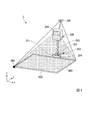
図1は、本発明の一実施形態に係るリハビリテーション支援システム1のシステム構成を示す斜視図である。リハビリテーション支援システム1は、リハビリテーションの対象者(以下「対象者」という。)に対して、リハビリテーションの実施を支援するシステムである。リハビリテーション支援システム1は、センサ100(位置取得手段の一例)、出力装置200及びリハビリテーション支援制御装置300を備える。
FIG. 1 is a perspective view showing a system configuration of a
センサ100は、同センサ100の検出範囲800内(図1の破線で囲った範囲)で対象者EPを検出する。
センサ100は、例えば、画像センサ、赤外線センサ、レーザセンサ、サーモセンサなど、対象者EPにマーカを装着することなく対象者EPの動きが検出できるセンサである。本実施形態では、このようなセンサの例として、センサ100に、距離センサと画像センサを組み込んだKinect(登録商標)を用いた場合を例に説明を行う。
センサ100は、例えば、画像センサ(不図示)を備える。前記画像センサは、(1)自らの正面方向をリアルタイムに撮像し、連続した複数枚の2次元画像(フレーム画像)を取得する動画カメラとしての機能と、(2)センサ100から、前記2次元画像(フレーム画像)内の各位置に対応する実際の位置までの距離の情報(距離情報を表示した画像)を取得する距離センサ(デプスセンサ)としての機能と、を有している。前記距離センサが有する機能により、対象者EPを撮像した画像と、当該画像に撮像された対象者EPの体の各部位の3次元空間における座標情報である距離画像情報とを取得する。センサ100が検出する3次元空間とは、図1に示すXYZ直交座標系によって示される空間である。
対象者EPの体の各部位とは、対象者EPの動作を認識するために検出することが求められる体の部位である。具体的には、対象者EPの体の各部位とは、例えば、対象者EPの頭、肩、腕、手、腰、足及び各関節部等の位置である。
センサ100は、検出した結果を示す情報(以下「検出結果情報」という。)をリハビリテーション支援制御装置300に出力する。検出結果情報とは、例えば、対象者EPの体の一部の位置情報である。
なお、センサ100は、対象者EPにマーカを装着し、そのマーカの検出により対象者EPを検出するセンサであっても構わない。
The
The
The
Each part of the body of the subject EP is a body part that needs to be detected in order to recognize the motion of the subject EP. Specifically, each part of the body of the subject EP is, for example, the position of the head, shoulders, arms, hands, hips, feet, and joints of the subject EP.
The
Note that the
出力装置200は、対象者EPに対して行われるリハビリテーションに関する画像を出力する。出力装置200は、例えば、プロジェクタ等の画像投影装置である。出力装置200は、リハビリテーションを支援する画像を投影して、出力領域900に表示する。出力画像の例としては、対象者EPの体の一部の位置の移動履歴、及び、対象者EPの体の一部の移動目標位置を含む画像を挙げることができる。例えば、歩行のリハビリテーションの場合、出力装置200が対象者EPの足の位置の移動履歴、及び、対象者EPが足を動かして移動させる目標位置のうちいずれか一方又は両方を表示するようにしてもよい。また、手の移動のリハビリテーションの場合であれば、出力装置200が、対象者EPの手の位置の移動履歴、及び、対象者EPが手を動かして移動させる目標位置のうちいずれか一方又は両方を表示するようにしてもよい。以下の説明では、対象者EPの体の一部の位置の移動履歴を示す画像を履歴画像と称する。また、対象者EPの体の一部の移動目標位置を示す画像を目標画像と称する。
例えば、足跡が表示されて対象者がその足跡の表示上に足を移動させるリハビリテーションの場合、足跡が目標画像である。また、例えば、横断歩道が表示されてその横断歩道を横断する際に近づいて来る自動車をよけるリハビリテーションの場合、表示された自動車が目標画像である。また、例えば、手の形をした移動先が表示されて手をその位置に移動させるリハビリテーションの場合、手の移動先を示す表示が目標画像である。また、例えば、リンゴの形状をした表示の表示位置に手を移動させるリハビリテーションの場合、表示されたリンゴが目標画像である。また、例えば、炎の形状をした表示が表示され、表示された炎に手が触れないように手を移動させるリハビリテーションの場合、表示された炎が目標画像である。なお、目標画像は、大きさ、表示位置、形状など、実行されるリハビリテーションに応じてさまざまに変化するものであってよい。
The
For example, in the case of rehabilitation in which a footprint is displayed and the subject moves his or her foot on the display of the footprint, the footprint is the target image. Further, for example, in the case of rehabilitation in which a pedestrian crossing is displayed and a car approaching when crossing the pedestrian crossing is displayed, the displayed vehicle is the target image. Also, for example, in the case of rehabilitation in which a hand-shaped destination is displayed and the hand is moved to that position, the display indicating the destination of the hand is the target image. Also, for example, in the case of rehabilitation in which a hand is moved to a display position of an apple-shaped display, the displayed apple is the target image. Further, for example, in the case of rehabilitation in which a display in the shape of a flame is displayed and the hand is moved so that the hand does not touch the displayed flame, the displayed flame is the target image. Note that the target image may be variously changed according to the rehabilitation to be performed, such as a size, a display position, and a shape.
リハビリテーション支援制御装置300は、情報処理装置を用いて構成される。すなわち、リハビリテーション支援制御装置300は、バスで接続されたCPU(Central Processor Unit)、メモリ及び補助記憶装置を備える。リハビリテーション支援制御装置300は、リハビリテーション支援プログラムを実行することによって動作する。
The rehabilitation
センサ100等は、脚部310によって支持される。脚部310は、上下方向に伸縮可能であり、センサ100、出力装置200の高さ位置を調整することができる。これにより、センサ100による検出範囲の広さを調整することが可能である。また、出力装置200が投影装置の場合、出力領域900の広さを調整することが可能である。また、脚部310は、キャスター311、312、313、314を備えている。キャスター311〜314は転動可能であるため、手押しなどすることにより、リハビリテーション支援システム1を、フロア上で自由に移動させることができる。
The
図2は、リハビリテーション支援システム1に備わるリハビリテーション支援制御装置300の機能構成例を示す概略ブロック図である。リハビリテーション支援制御装置300は、入力部31、出力部32、記憶部33、制御部34、操作部35及び表示部36を備える。
入力部31は、外部からの情報を入力するインタフェースである。例えば、入力部31は、センサ100から検出結果を示す情報(検出結果情報)を取得する。
出力部32は、制御部34によって生成された画像を出力装置200に対して出力するインタフェースである。
FIG. 2 is a schematic block diagram illustrating a functional configuration example of the rehabilitation
The
The
記憶部33は、磁気ハードディスク装置や半導体記憶装置等の記憶装置を用いて構成される。記憶部33は、キャリブレーション情報記憶部331、判定条件情報記憶部332、検出履歴情報記憶部333、パラメータ情報記憶部334、プログラム情報記憶部335として機能する。
The
キャリブレーション情報記憶部331は、キャリブレーション情報を記憶する。キャリブレーション情報は、センサ100の検出結果を示す座標の座標系と、出力装置200が投影する画像面の座標系とを対応付ける情報である。従って、リハビリテーション支援制御装置300におけるキャリブレーションは、センサ100による検出範囲800と、出力装置200による画像の出力領域900との位置関係を把握し、両者に共通の座標系を設定する処理である。なお、センサ100が検出できる検出範囲は、図示する検出範囲800より広くてもよい。本実施形態における検出範囲800とは、出力領域900上で行われる対象者EPの動作において、対象者EPの検出目的とする体の一部の位置情報を取得するのに必要な検出範囲のことである。なお、出力領域900上とは、出力領域900で規定される平面の領域だけではなく、その領域において、出力領域900を基準とする所定高さまでの空間も含む。
The calibration
キャリブレーション情報は、例えば事前にキャリブレーションを実施することによって得てもよい。
より具体的には、例えば出力装置200がキャリブレーション用のマーカ画像を、画像面(画像の出力領域900)の四隅など、複数箇所に投影する。リハビリテーション支援制御装置300は、出力装置200の座標系における座標を既知である。
The calibration information may be obtained, for example, by performing calibration in advance.
More specifically, for example, the
出力装置200がマーカ画像を投影すると、センサ100は、各マーカ画像の位置を、センサ100の座標系(センサ100が検出位置を示すのに用いる座標系)における座標にてリハビリテーション支援制御装置300へ出力する。これにより、リハビリテーション支援制御装置300(制御部34)は、各マーカの位置を、センサ100の座標系における座標、及び、出力装置200の座標系における座標の両方で取得する。また、リハビリテーション支援制御装置300(制御部34)は、四隅等に投影されたマーカ画像により、出力装置200の座標系における出力領域900の範囲を示す座標を把握する。これにより、後述する目標決定部345は、出力領域900における出力装置200の座標系における目標位置を計算することができる。
When the
リハビリテーション支援制御装置300(制御部34)は、得られた座標に基づいて、センサ100の座標系を補正するための情報をキャリブレーション情報として取得する。センサ100が座標系調整機能を有している場合、リハビリテーション支援制御装置300(制御部34)は、この機能を利用してセンサ100の座標系を出力装置200の座標系に合わせるためのキャリブレーション情報を生成する。あるいは、出力装置200が座標系調整機能を有している場合、リハビリテーション支援制御装置300(制御部34)が、この機能を利用して出力装置200の座標系をセンサ100の座標系に合わせるためのキャリブレーション情報を生成するようにしてもよい。
The rehabilitation support control device 300 (the control unit 34) acquires information for correcting the coordinate system of the
床面が光を散乱させてマーカ画像がぼやける場合など、センサ100によるマーカ画像の検出が困難な場合は、マーカ画像を用いた位置検出の代わりに理学療法士等の操作者が手動で位置検出を行うようにしてもよい。出力装置200が出力領域900の全体に画像を投影している状態で、センサ100が画像センサで投影画像全体を含む領域を撮像する。リハビリテーション支援制御装置300は、センサ100による撮像画像を表示画面に表示する。そして、リハビリテーション支援システム1の操作者は、モニタ画面に表示されている出力領域900の四隅の各々をタッチ操作にて指定する。
モニタ画面に表示されている画像は、センサ100が撮像した画像なので、操作者が指定した位置をセンサ100の座標系における座標で取得し得る。リハビリテーション支援制御装置300(制御部34)は、この座標と、出力装置200の座標系における出力領域900の四隅の座標とに基づいて、キャリブレーション情報を取得する。なお、高さ方向の座標として、フロアの座標を用いる。
あるいは、理学療法士等が、例えばコーンなど物理的なマーカを画像面の四隅位置に置くようにしてもよい。この場合、センサ100は、置かれたマーカを検出し、各マーカの座標を出力する。
When it is difficult to detect the marker image by the
Since the image displayed on the monitor screen is an image captured by the
Alternatively, a physical therapist or the like may place physical markers such as cones at the four corners of the image plane. In this case, the
出力装置200が床面に画像を投影する場合、リハビリテーション支援システム1の初回使用時にキャリブレーションを行えば、2回目の使用時以降はキャリブレーションを行う必要が無い。センサ100と床面との位置関係、及び、出力装置200と床面との位置関係のいずれも変わらないため、初回使用時に得られたキャリブレーション情報を2回目以降の使用時にも使用できるためである。
When the
判定条件情報記憶部332は、動作領域を判定するための条件を記憶する。動作領域については後述する。
検出履歴情報記憶部333は、認識部341が認識した対象者EPの体の一部に関する位置情報(検出結果情報)の履歴を記憶する。例えば、歩行のリハビリテーションを行う場合、検出履歴情報記憶部333は、対象者EPの足の位置の検出結果情報の履歴を記憶する。また、手の移動のリハビリテーションを行う場合、検出履歴情報記憶部333は、対象者EPの手の位置の検出結果情報の履歴を記憶する。
The determination condition
The detection history
パラメータ情報記憶部334は、後述する足用表示パラメータ設定部347が設定した足用表示パラメータ、後述する手用表示パラメータ設定部348が設定した手用表示パラメータ、後述する外乱用表示パラメータ設定部349が設定した外乱用表示パラメータを記憶する。
プログラム情報記憶部335は、リハビリテーション支援プログラムを記憶する。
The parameter
The program
制御部34は、CPUを用いて構成される。制御部34は、リハビリテーション支援プログラムを実行することによって、認識部341、表示制御部342、動作領域判定部343、記録部344、目標決定部345、評価部346、足用表示パラメータ設定部347、手用表示パラメータ設定部348、外乱用表示パラメータ設定部349として機能する。
The
認識部341は、入力部31が取得した検出結果情報を取得し、検出結果情報が示す対象物を認識する。例えば、認識部341は、検出結果情報に基づいて、検出範囲800に存在する人、テーブル、床、壁等を認識する。例えば、Kinect(登録商標)を用いると、対象者EPの人体上の複数の部位の位置を認識することができる。例えば、認識部341は、テーブル上の長尺状の検出対象の先端部を認識すると、その先端部の単位時間ごとの位置情報を検出する。認識部341は、センサ100が時々刻々と検出したこれらの特徴点の位置情報により、対象者EPの体の一部の位置の動きを認識する。例えば、長尺状の対象物を検出した場合、認識部341は、その対象物の先端の位置の動きを認識する。当該先端の位置の動きは、例えば、対象者EPの手の位置として扱ってもよい。また、認識部341は、検出結果情報が示す対象物の形状と人の骨格モデルとの比較を行って対象物が人と認識できる場合、各部位の位置を認識する機能を有していてもよい。この機能によれば、認識部341は、人体の各部位の位置情報を、その部位に対応付けて認識することができる。例えば、対象者EPがセンサ100の前で直立する。すると、認識部341は、その状態で検出された検出結果情報と人の骨格モデルとの比較を行い、対象物が人の形状をしていることから対象物は人であると認識する。さらに、認識部341は、例えば、左のつま先とその位置情報、右のかかととその位置情報、左右の手首とそれぞれの位置情報というように、各部位の位置情報をそれぞれの部位に対応付けて認識する。骨格モデルによる各部位の位置を認識する機能(以下「骨格トラッキング機能」という。)を用いると、認識部341は、対象者EPの各部位の位置の動きを認識することができる。このように認識部341は、検出結果情報に含まれる所定の形状をした対象物の所定の位置をトラッキングすることにより、又は、骨格トラッキング機能により、対象者EPの体の一部の位置およびその動きを認識する。また、Kinect(登録商標)を用いると、検出範囲800に存在する物の座標情報(検出範囲800に存在する物の所定間隔ごとの座標情報を含む点群データ)を得ることができる。認識部341は、検出結果情報(点群データ)を分析し、所定の広さ以上の面積を有し、Z座標の値が変化しない面(要するに、Z座標の値がほぼ一定の点群の集合)を、壁、フロア、テーブル等との平面として認識する。また、認識部341は、検出結果情報のうち、どのデータが、後述する動作領域判定部343が判定した動作領域に関連する対象者EPの体の一部(検出対象部位)の検出データであるかを認識し、そのデータ(検出対象情報)を選択する。
The recognizing
ここで、動作領域とは、対象者EPのリハビリテーションの目的とする動作が行われる領域のことである。より具体的には、リハビリテーションによって回復することを目的とする動作に強く関連する部位が動作する空間内の所定の領域のことである。また、例えば、動作領域とは、対象者EPがリハビリテーションにおいてその部位を近接させる領域である。また、例えば、動作領域とは、対象者EPのリハビリテーションにおいて、その動作の目標(到達点)となる位置を含む領域である。また、動作領域とは、対象者EPがリハビリテーション中に目的とする動作を行う場所である。動作領域の具体例として、2次元領域の場合では、フロア、テーブル等を挙げることができる。例えば、フロアであれば、リハビリテーションによって回復することを目的とする動作に強く関連する部位は足であり、テーブルの場合の当該部位は手である。また、対象者EPは、歩行動作のリハビリテーションにおいて足をフロアに近接させ、手の移動のリハビリテーションにおいては手をテーブルに近接させる。また、例えば、歩行動作のリハビリテーションにおいてフロアは、歩行動作の到達点となる位置(目標画像の表示位置)を含む領域であり、テーブルは手の移動のリハビリテーションにおける手の到達点となる位置(目標画像の表示位置)を含む領域である。また、フロア、テーブルはそれぞれ、歩行動作のリハビリテーション、手の移動のリハビリテーション中に目的となる動作を行う場所である。なお、動作領域が3次元である場合の具体例としては、テーブル上のテーブル表面を基準とする所定高さの範囲の空間(以下「3次元動作領域」という)を挙げることができる。例えば、出力装置200は、テーブルに「10cm」を意味する目標画像を表示する。例えば、テーブル上のある位置に「10cm」と表示してもよい。これは、テーブルの当該目標画像が表示された位置の真上の空間の、テーブル表面を基準とする高さ10cmの位置が、手の到達点となる位置であることを意味する目標画像である。この目標画像が示す位置は、当該3次元動作領域に含まれている。この例の場合も、例えば、3次元動作領域は、リハビリテーションによって回復することを目的とする動作に強く関連する部位(手)が動作する領域である。また、3次元動作領域は、手の移動のリハビリテーションにおいて、手を近接させる領域である。また、3次元動作領域は、手の移動の到達点となる位置(目標画像が示す位置)を含む領域である。また、3次元動作領域は、対象者EPが手の移動のリハビリテーション中に目的とする動作を行う場所である。なお、動作領域が3次元である場合の他の例として、出力領域900上の空間を挙げることができる。例えば、動作領域が出力領域900上の空間の場合、この空間に目標画像を投影し、対象者EPがその目標画像を手で触れる等のリハビリテーションを行ってもよい。
Here, the operation area is an area in which an operation intended for rehabilitation of the target person EP is performed. More specifically, it refers to a predetermined area in a space in which a part strongly related to an operation intended to be recovered by rehabilitation operates. Also, for example, the operation area is an area where the subject EP approaches the part in rehabilitation. In addition, for example, the operation area is an area including a position that is a target (an arrival point) of the operation in the rehabilitation of the target person EP. The operation area is a place where the target person EP performs a target operation during rehabilitation. As a specific example of the operation area, in the case of a two-dimensional area, a floor, a table, and the like can be given. For example, in the case of a floor, a part strongly related to an operation intended to recover by rehabilitation is a foot, and in the case of a table, the part is a hand. In addition, the target person EP brings his / her feet closer to the floor in the rehabilitation of the walking motion, and brings his / her hands closer to the table in the rehabilitation of the hand movement. Further, for example, in the rehabilitation of the walking motion, the floor is an area including a position (display position of the target image) which is a reaching point of the walking motion, and the table is a position (target) of the hand in the rehabilitation of hand movement. (Display position of the image). Further, the floor and the table are places where the target operation is performed during the rehabilitation of the walking motion and the rehabilitation of the hand movement, respectively. As a specific example in the case where the operation area is three-dimensional, a space having a predetermined height range based on the table surface on the table (hereinafter, referred to as “three-dimensional operation area”) can be given. For example, the
表示制御部342は、出力装置200が出力する画像を生成する。例えば、表示制御部342は、動作領域に表示して対象者EPの動作を誘導する目標画像、リハビリテーションの評価結果の情報を含む画像、リハビリテーション中に行った対象者EPの検出対象部位の動作の軌跡を示す画像などを生成する。
The
動作領域判定部343は、認識部341による認識結果に基づいて動作領域を判定する。後述するように、動作領域の判定方法は、様々であってよい。動作領域判定部343は、所定の判定条件に基づいて、例えば、動作領域がフロアであると判定する。また、例えば、動作領域判定部343は、動作領域がテーブルであると判定する。
The operation
動作領域判定部343は、動作領域を判定すると、対象者EPの動作領域に関連する検出対象となる部位(検出対象部位)を決定する。検出対象部位とは、リハビリテーションの目的とする動作に関係が深い体の一部である。例えば、動作領域判定部343は、動作領域をフロアであると判定した場合、対象者EPの足首を検出対象部位として決定する。あるいは、動作領域判定部343は、対象者EPのつま先を検出対象部位として決定してもよい。また、例えば、動作領域判定部343は、動作領域をテーブルであると判定した場合、対象者EPの手の甲を検出対象部位として決定する。あるいは、動作領域判定部343は、対象者EPの指先を検出対象部位として決定してもよい。
When determining the operation area, the operation
なお、動作領域に関連する検出対象部位は、予め記憶部33に設定されており、動作領域判定部343は、その情報と自らが判定した動作領域とに基づいて検出対象部位を決定する。検出対象部位には、例えば、リハビリテーションの目標とする動作において、動作範囲が大きい部位が設定されていてもよい。例えば、歩行動作のリハビリテーションであれば、動作範囲が大きい部位は、対象者EPの足(足首、つま先、踵など)である。移動のリハビリテーションであれば、動作範囲が大きい部位は、対象者EPの手(手首、指先、手の甲など)である。
Note that the detection target portion related to the operation region is set in the
あるいは、検出対象部位には、表示制御部342が生成する目標画像の表示位置に近接する部位が設定されていてもよい。例えば、歩行動作のリハビリテーションの場合、本実施形態では、対象者EPが歩行動作において足を踏み出すべき位置に足型などを模した目標画像を表示するが、この場合、目標画像の表示位置に近接する部位とは、対象者EPの足(足首、つま先、踵など)である。また、手の移動のリハビリテーションの場合、対象者EPがタッチすべき位置に目標画像を表示するが、この場合、目標画像の表示位置に近接する部位とは、対象者EPの手(手首、指先、手の甲など)である。
Alternatively, a part close to the display position of the target image generated by the
なお、認識部341は、検出結果情報に含まれる動作領域判定部343が決定した検出対象部位のデータ(体の一部の位置情報)を、記録部344を介して、検出履歴情報記憶部333に記録する。
記録部344は、検出結果情報を検出履歴情報記憶部333に書き込んで記録する。
The recognizing
The
目標決定部345は、認識部341が認識する対象者EPの体の一部(検出対象部位)の位置に基づいて対象者EPの体の一部の目標位置を決定する。例えば、歩行のリハビリテーションの場合、目標決定部345は、対象者EPの現在の足の位置、及び、対象者EPの足の位置の履歴のうち少なくともいずれかに基づいて、対象者EPの足の移動目標位置を決定する。特に、目標決定部345が、対象者EPの足の位置の履歴に基づいて対象者EPの進行方向を判定し、判定した進行方向に応じて移動目標位置を決定するようにしてもよい。あるいは、目標決定部345が、対象者EPの足の向きに基づいて対象者EPの進行方向を判定し、判定した進行方向に応じて移動目標位置を決定するようにしてもよい。あるいは、目標決定部345が、対象者EPの進行方向にかかわらず、例えばランダムな向きに、或いは所定のゴールの位置に向けて、移動目標位置を決定するようにしてもよい。
The
目標決定部345が、対象者EPの体の検出対象部位の移動量を算出し、算出した移動量に基づいて移動目標位置を決定するようにしてもよい。例えば、認識部341が対象者EPの足の位置を認識する場合、目標決定部345は、対象者EPの足の位置の履歴に基づいて対象者EPの歩幅を算出する。そして、目標決定部345は、対象者EPの足の現在位置から歩幅分だけ移動した位置に移動目標位置を設定する。対象者EPの歩幅は、対象者EPの足の移動量を示しており、対象者EPの体の検出対象部位の移動量の例に該当する。
認識部341が対象者EPの足の位置の動きを認識する場合、目標決定部345が、対象者EPの足が動いた間隔を歩幅として検出するようにしてもよい。あるいは、認識部341が、対象者EPが床面に足をついた位置を認識する場合、目標決定部345が、対象者EPが床面に足をついた位置から次に足をついた位置までの間隔を歩幅として検出するようにしてもよい。
The
When the
評価部346は、対象者EPの体の検出対象部位の位置と移動目標位置との位置関係を評価する。例えば、評価部346は、認識部341が認識した対象者EPの体の部位の位置と、目標決定部345が決定した移動目標位置との距離を算出する。そして、評価部346は、算出した距離が所定の閾値以下か否かを判定する。対象者EPの体の検出対象部位と移動目標位置との距離が閾値以下であると判定した場合、評価部346は、目標位置到達と評価する。一方、対象者EPの体の検出対象部位と移動目標位置との距離が閾値より大きいと判定した場合、評価部346は、目標位置不到達と評価する。
The
評価部346が用いる距離の閾値は、複数の対象者EPに共通に予め設定された定数であってもよい。あるいは、評価部346が、対象者EPの歩幅の10分の1を閾値に設定するなど対象者EP毎に閾値を設定するようにしてもよい。また、評価部346が用いる距離の閾値は、複数種類のリハビリテーションに共通に設定されていてもよいし、リハビリテーションの種類毎に設定されていてもよい。また閾値の大きさは、手を移動させるリハビリテーションよりも足を移動させるリハビリテーションの方が大きくなるよう設定されていてもよい。
The threshold value of the distance used by the
また、評価部346が、対象者EPの体の一部の位置(検出対象部位)と移動目標位置との相対的な位置関係を評価する段階数は、上述した目標位置到達又は目標位置不到達の2段階に限らず、3段階以上の多段階であってもよい。例えば、評価部346が、目標位置到達か否かの判定閾値に加えてさらに目標位置不到達の場合のずれの大小の判定閾値を用いて、目標位置到達、ずれ小、ずれ大の3段階で評価を行うようにしてもよい。
In addition, the number of steps in which the
また、評価部346が対象者EPの体の検出対象部位の位置と移動目標位置との位置関係を評価する方法は、閾値を用いる方法のみに限らない。例えば、評価部346が、対象者EPの体の検出対象部位の位置と移動目標位置との重なりの有無を判定し、重なり有りと判定した場合に目標位置到達と評価するようにしてもよい。
さらに、例えば歩行のリハビリテーションの場合、目標決定部345が、移動目標位置を面積のある範囲にて床面上に決定し、認識部341が、対象者EPの足の位置を、対象者EPの足の形状の範囲にて認識するようにしてもよい。そして、評価部346が、移動目標位置として決定されている範囲と、対象者EPの足の位置として検出された範囲との重なりの有無を判定するようにしてもよい。
The method by which the
Furthermore, for example, in the case of walking rehabilitation, the
足用表示パラメータ設定部347は、歩行などの足を移動させるリハビリテーションにおいて、足用表示パラメータを設定する。足用表示パラメータは、対象者EPが足を移動させるときの目標画像の表示に用いられるパラメータである。
手用表示パラメータ設定部348は、手を動かすリハビリテーションにおいて、手用表示パラメータを設定する。手用表示パラメータは、対象者EPが手を動かすときの目標画像の表示に用いられるパラメータである。
外乱用表示パラメータ設定部349は、外乱用表示パラメータを設定する。外乱用表示パラメータは、リハビリテーションの対象者EPが足または手を所定の目標画像まで移動させるときに、対象者EPが足または手を目標画像まで移動させる妨げとなる外乱の表示に用いられるパラメータである。または、外乱用表示パラメータは、リハビリテーションの対象者EPが足または手を回避目標となる目標画像から回避させるときに、対象者EPが足または手を目標画像から回避させる妨げとなる外乱の表示に用いられるパラメータである。
例えば、足跡が表示されて対象者がその足跡の表示上に足を移動させるリハビリテーションにおいて、足を移動させている最中に自動車が近づいて来て足の移動を妨げる場合、表示された自動車が外乱である。また、例えば、リンゴの形状をした表示の表示位置に手を移動させるリハビリテーションにおいて、表示されたリンゴの位置に手を移動させている最中に炎が表示されて手の移動を妨げる場合、表示された炎が外乱である。なお、外乱は、大きさ、表示位置、形状など、実行されるリハビリテーションに応じてさまざまに変化するものであってよい。また、足を移動させるリハビリテーションにおいて、対象者が自動車を避けながら横断歩道を渡る際に、横断歩道に穴が表示され自動車を避けることを妨げる場合、表示された穴が外乱である。また、手を移動させるリハビリテーションにおいて、手を炎に触れないように移動させる際に、手に触れたくない手の移動範囲を制限するゴキブリなどが表示される場合、表示されたゴキブリが外乱である。
The foot display
The hand display
The disturbance display
For example, in rehabilitation in which footprints are displayed and the subject moves his or her feet on the footprints display, when the car approaches and hinders the movement of the feet while moving the feet, the displayed car is It is a disturbance. Also, for example, in rehabilitation in which the hand is moved to the display position of the display in the shape of an apple, when a flame is displayed while moving the hand to the position of the displayed apple and hinders the movement of the hand, the display is performed. The fire is a disturbance. Note that the disturbance may change variously according to the rehabilitation to be performed, such as the size, the display position, and the shape. Also, in the rehabilitation for moving a foot, when a subject crosses a pedestrian crossing while avoiding a car, if a hole is displayed on the pedestrian crossing to prevent the car from being avoided, the displayed hole is a disturbance. In addition, in rehabilitation in which a hand is moved, when a hand is moved so as not to touch the flame, if a cockroach or the like that restricts a moving range of a hand that the user does not want to touch is displayed, the displayed cockroach is a disturbance. .
操作部35は、キーボード、ポインティングデバイス(マウス、タブレット等)、ボタン、タッチパネル等の既存の入力装置を用いて構成される。操作部35は、理学療法士等の指示をリハビリテーション支援制御装置300に入力する際に理学療法士等によって操作される。操作部35は、入力装置をリハビリテーション支援制御装置300に接続するためのインタフェースであってもよい。この場合、操作部35は、入力装置において理学療法士等の入力に応じ生成された入力信号をリハビリテーション支援制御装置300に入力する。操作部35は、表示部36と一体のタッチパネルとして構成されてもよい。
The
表示部36は、CRT(Cathode Ray Tube)ディスプレイ、液晶ディスプレイ、有機EL(Electro Luminescence)ディスプレイ等の画像表示装置である。表示部36は、画像や文字を表示する。表示部36は、画像表示装置をリハビリテーション支援制御装置300に接続するためのインタフェースであってもよい。この場合、表示部36は、画像や文字を表示するための映像信号を生成し、自身に接続されている画像表示装置に映像信号を出力する。
The
図3は、リハビリテーション支援制御装置300による第一動作領域を説明するための斜視図である。
図3は、対象者EPがテーブルT(第一動作領域)上で手の移動のリハビリテーションを行っている様子を示している。出力装置200は、テーブルTに目標画像M1を投影している。対象者EPは、出力装置200が出力領域900に出力する目標画像M1に基づいて、手の移動に関するリハビリテーションを行う。
センサ100は、対象者EPが検出範囲800内において手を移動する際の対象者EPの体の一部の位置を検出し、検出結果情報を所定の時間毎にリハビリテーション支援制御装置300に出力する。
FIG. 3 is a perspective view for explaining a first operation area by the rehabilitation
FIG. 3 shows a state in which the target person EP is performing rehabilitation of hand movement on the table T (first operation area). The
The
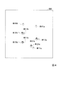
図4は、リハビリテーション支援システム1における画像の表示例を示す平面図である。図4では、リハビリテーション支援システム1を用いて手の移動のリハビリテーションを行う場合の画像の例を示している。図4の例では、出力装置200の画像の投影によって、机上の投影面(出力領域900)に画像が表示されている。具体的には、目標位置の履歴を示す目標画像M111a、M111b、M112a及びM112bと、対象者EPの手の位置の履歴画像M121a及びM121bと、対象者EPの現在の手の位置を示す画像M131a及びM131bと、次の目標位置を示す目標画像M141a及びM141bとが、それぞれ手の形の画像で示されている。図4では、符号の「a」は右手を示し、「b」は左手を示す。例えば、目標画像M111aは、右手の目標位置の履歴を示す。目標画像M111bは、左手の目標位置の履歴を示す。
FIG. 4 is a plan view showing a display example of an image in the
但し、リハビリテーション支援システム1におけるこれらの画像は、体の検出対象部位の形状の画像に限らない。例えば、出力装置200が、右手の目標位置を赤丸で表示し、左手の目標位置を青丸で表示するなど、体の検出対象部位の形状の画像に代えて丸印を表示するようにしてもよい。
However, these images in the
このように、表示制御部342が、出力装置200を制御してテーブルTに目標画像および履歴画像を表示させることで、対象者EPが、直感的に自分が目標に対して手を移動させた実績を把握できる。
As described above, the
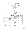
図5は、リハビリテーション支援制御装置300による第二動作領域を説明するための斜視図である。
図5は、対象者EPがフロアFL(第二動作領域)上で歩行動作のリハビリテーションを行っている様子を示している。出力装置200は、フロアFLに目標画像M2〜M5を投影している。対象者EPは、出力装置200が出力領域900に出力する目標画像M2〜M5に基づいて、歩行動作のリハビリテーションを行う。例えば、対象者EPは、目標画像M2〜M5に示されるスタート位置から目標位置まで歩行するリハビリテーションを行う。センサ100は、対象者EPが検出範囲800内において対象者EPの足の位置を検出し、検出結果情報を所定の時間毎にリハビリテーション支援制御装置300に出力する。
FIG. 5 is a perspective view for explaining a second operation area by the rehabilitation
FIG. 5 shows a state in which the target person EP is performing rehabilitation of a walking motion on the floor FL (second motion area). The
図6は、リハビリテーション支援システム1における画像の表示の例を示す平面図である。
図6は、リハビリテーション支援システム1における画像の表示の、もう1つの例を示す図である。図6では、リハビリテーション支援システム1を用いて歩行のリハビリテーションを行う場合の画像の例を示している。図6の例では、出力装置の画像の投影によって、床上の投影面(出力領域900)に画像が表示されている。具体的には、目標位置の履歴を示す目標画像M211〜M214と、対象者EPの足の位置の履歴画像M221〜M223と、対象者EPの現在の足の位置を示す画像M231と、次の目標位置を示す目標画像M241とが、それぞれ足の形の画像で示されている。
FIG. 6 is a plan view illustrating an example of displaying an image in the
FIG. 6 is a diagram illustrating another example of the display of an image in the
図4の例では、右手、左手それぞれの目標位置が表示されていたのに対し、図6の例では、左足の次の目標画像M241が示されているものの、右足の次の目標画像は示されていない。手の移動では、右手と左手とを同時に動かし得るのに対し、歩行では右足と左足とを交互に動かすからである。なお、本実施形態のリハビリテーション支援システム1によれば、足の動作のリハビリテーションとして、歩行(左右の足を交互に踏み出す動作)だけではなく、片足だけを連続して移動させたり、「けんけんぱ」のように両足を同時に移動させたりする足の動作を訓練することも可能である。その場合、出力装置200は、それぞれの足の動作に応じた目標画像、履歴画像を出力領域900に出力する。
なお、図4を参照して説明したのと同様、出力装置200が表示する画像は、足の形の画像に限らない。例えば、出力装置200が、右足の目標位置を赤丸で表示し、左足の目標位置を青丸で表示するなど、足の形の画像に代えて丸印を表示するようにしてもよい。また上記の実施形態とは逆に、左右の足の目標画像を片方ずつ表示するのではなく、常に先行して左右の足の目標画像を共に表示するようにしてもよい。また現在の足の位置画像と過去の足の位置の履歴画像で異なる表示とすることも可能である。例えば現在の足の位置画像は円、方形などの図形で表示し、過去の左右の足の履歴画像は「足あと」の図形で表示してもよい。
In the example of FIG. 4, the target positions of the right hand and the left hand are displayed, whereas in the example of FIG. 6, the next target image M241 of the left foot is shown, but the next target image of the right foot is shown. It has not been. This is because the right hand and the left hand can be moved simultaneously in the movement of the hand, while the right foot and the left foot are moved alternately in the walking. In addition, according to the
Note that, as described with reference to FIG. 4, the image displayed by the
このように、表示制御部342が、出力装置200を制御してフロアFLに目標画像および履歴画像を表示させることで、対象者EPが、直感的に自分が目標に対して足を移動させた実績を把握できる。
As described above, the
次に図7を用いて、対象者のリハビリテーション検出対象情報の検出および記録処理の流れについて説明する。
図7は、リハビリテーション支援制御装置300による動作領域の判定処理の一例を示すフローチャートである。
まず、理学療法士又は作業療法士がこれから行おうとするリハビリテーション内容に応じて、対象者EPがリハビリテーションを行う環境にリハビリテーション支援システム1を移動させる。また、脚部310の高さを適切に調節する。次に、対象者EPが、検出範囲800で、これから行うリハビリテーション内容に応じた姿勢を取る。例えば、テーブル上での腕のリハビリテーションを行う場合であれば、対象者EPは椅子に座ってテーブル上に手を置く姿勢を取る。また、例えば、歩行動作のリハビリテーションを行う場合、対象者EPは起立した姿勢を取る。対象者EPがこれらの姿勢を取ると、理学療法士等がリハビリテーション支援制御装置300に準備開始指示情報を入力する。操作部35は、その準備開始指示情報を取得する(ステップS10)。なお、理学療法士等がリハビリテーション支援制御装置300に準備開始指示情報を入力した後に、対象者EPが、検出範囲800で、これから行うリハビリテーション内容に応じた姿勢を取っても良い。
Next, the flow of detection and recording processing of rehabilitation detection target information of the target person will be described with reference to FIG.
FIG. 7 is a flowchart illustrating an example of an operation area determination process performed by the rehabilitation
First, the
すると、センサ100が検出を開始し、入力部31は、検出結果情報を取得する(ステップS11)。入力部31は、検出結果情報を制御部34へ出力する。制御部34では、認識部341が検出結果情報を取得し、対象者EPの動作を認識する。あるいは、認識部341は、検出範囲800に存在するテーブル、フロア等を認識する。認識部341は、認識結果を動作領域判定部343へ出力する。
Then, the
次に動作領域判定部343は、図3、図5を用いて説明した方法によって動作領域を判定する(ステップS12)。例えば、動作領域判定部343は、認識部341による認識結果が、対象者EPの全身を認識したことを示していれば、動作領域はフロアFLであると判定してもよい。また、例えば、動作領域判定部343は、認識結果がテーブルTの存在を示していれば、動作領域はテーブルTであると判定してもよい。動作領域判定部343は、この他にも、上述した様々な判定方法を用いて動作領域の判定を行うことができる。次に動作領域判定部343は、動作領域はフロアFLかどうかを判定する(ステップS13)。動作領域がフロアFLの場合(ステップS13;Yes)、動作領域判定部343は、検出対象部位を対象者EPの足(例えば、足首又はつま先)に設定する(ステップS17)。動作領域判定部343が、検出対象部位を対象者EPの足に設定すると、次に足用表示パラメータ設定部347は、足を移動させるリハビリテーションにおける足用表示パラメータを設定する(ステップS18)。足用表示パラメータは、対象者EPが足を移動させるときの目標画像の表示に用いられるパラメータである。
Next, the operation
足用表示パラメータには、例えば、足用距離パラメータ、足用時間パラメータ、足用ベクトルパラメータなどが含まれる。足用距離パラメータには、例えば、目標画像が示す歩幅を決定するために用いられるパラメータ(図10に示すステップの値)、目標画像が示すスタンス(歩隔を含む)を決定するために用いられるパラメータ(図10に示す歩隔)などが含まれている。スタンスとは、対象者の前方(例えば体の前面や顔面が向く方向や進行予定の方向)に伸びる2本の平行線であって対象者の2つの脚の所定部位(例えば踵や親指の先端)をそれぞれ通る平行線の距離を表す。また、足用時間パラメータには、例えば、目標画像が表示されリハビリテーションが行われる総時間を示すパラメータ、現在表示されている目標画像が表示されてから目標画像が表示される次のタイミングまでの時間を示すパラメータなどが含まれている。また、足用ベクトルパラメータには、例えば、現在表示されている目標画像を基準とした次のタイミングに表示される目標画像の表示方向を決定するために用いられるパラメータなどが含まれる。足用表示パラメータ設定部347は、指定された足用距離パラメータ、足用時間パラメータ、足用ベクトルパラメータなどをパラメータ情報記憶部334に記録する。これらのパラメータを設定することにより、例えば、図6に例示したような足型の目標画像を対象者EPのリハビリテーションの内容に応じて表示することができる。
The foot display parameters include, for example, a foot distance parameter, a foot time parameter, a foot vector parameter, and the like. The foot distance parameter is used, for example, to determine a parameter (step value shown in FIG. 10) used to determine the stride indicated by the target image and a stance (including step distance) indicated by the target image. Parameters (steps shown in FIG. 10) and the like are included. The stance is two parallel lines extending in front of the subject (for example, the direction in which the front of the body or the face is facing or the direction in which the subject is going to travel) and is a predetermined portion of the two legs of the subject (for example, the tip of a heel or a thumb). ) Represents the distance between the parallel lines passing through each. The foot time parameter includes, for example, a parameter indicating the total time during which the target image is displayed and rehabilitation is performed, and a time from when the currently displayed target image is displayed until the next timing at which the target image is displayed. Is included. The foot vector parameters include, for example, parameters used to determine the display direction of the target image displayed at the next timing based on the currently displayed target image. The foot display
この他にも、例えば、足用表示パラメータ設定部347は、目標画像が、対象者EPが歩行するときの回避目標となるリハビリテーションの場合に、操作部35から入力された情報に応じて、足用表示パラメータを設定する。目標画像が、対象者EPが歩行するときの回避目標となるリハビリテーションとは、例えば、図11に示すように、リハビリテーション支援制御装置300が、対象者EPが横断歩道を歩行するときに回避目標となる自動車の形状をした目標画像を映し出し、対象者EPが目標画像を回避するリハビリテーションである。
なお、足用表示パラメータの設定及び足用表示パラメータを用いた表示制御部342による表示について、後に詳細に述べる。
なお、足用表示パラメータを設定するための表示は、リハビリテーション支援制御装置300の表示部36に表示されるものである。
In addition to this, for example, in the case where the target image is rehabilitation that is an avoidance target when the target person EP walks, the foot display
The setting of the foot display parameters and the display by the
The display for setting the foot display parameter is displayed on the
足用表示パラメータ設定部347が足用表示パラメータを設定すると、次に外乱用表示パラメータ設定部349は、足の外乱用表示パラメータを設定する(ステップS19)。例えば、リハビリテーション支援制御装置300が専用アプリケーションを実行し、理学療法士等がリハビリテーション支援制御装置300に対して種々の情報を入力する。外乱用表示パラメータ設定部349は、目標画像が、対象者EPが歩行するときの足の移動目標となるリハビリテーションの場合に、リハビリテーション支援制御装置300に入力された情報に応じて、外乱用表示パラメータを設定する。
外乱用表示パラメータは、例えば、図12で示したように、リハビリテーション支援制御装置300が、対象者EPが横断歩道を歩行するときに、リハビリテーションの対象者EPが足を所定の目標画像まで移動させる妨げとなる自動車の形状をした外乱を画像として映し出すために用いられるパラメータである。
When the foot display
For example, as shown in FIG. 12, the rehabilitation
足の外乱用表示パラメータには、例えば、外乱用距離パラメータ、外乱用時間パラメータ、外乱用ベクトルパラメータなどが含まれる。外乱用距離パラメータには、例えば、現在表示されている外乱から次のタイミングに表示される外乱までの距離を決定するために用いられるパラメータなどが含まれる。また、外乱用時間パラメータには、例えば、現在表示されている外乱が現在と異なる位置に表示されるまでの時間を示すパラメータなどが含まれる。また、外乱用ベクトルパラメータには、例えば、現在表示されている外乱を基準とした次のタイミングに表示される外乱の表示方向を決定するために用いられるパラメータが含まれる。外乱用表示パラメータ設定部349は、指定された外乱用距離パラメータ、外乱用時間パラメータ、外乱用ベクトルパラメータなどをパラメータ情報記憶部334に記録する。
The disturbance display parameters for the feet include, for example, a disturbance distance parameter, a disturbance time parameter, and a disturbance vector parameter. The disturbance distance parameter includes, for example, a parameter used to determine a distance from the currently displayed disturbance to the disturbance displayed at the next timing. Further, the disturbance use time parameter includes, for example, a parameter indicating a time until the currently displayed disturbance is displayed at a position different from the current position. Further, the disturbance vector parameters include, for example, parameters used for determining the display direction of disturbance displayed at the next timing based on the currently displayed disturbance. The disturbance display
一方、動作領域がフロアFLではない場合(ステップS13;No)。動作領域判定部343は、検出対象部位を手(例えば、手の甲又は指先)に設定する(ステップS14)。動作領域判定部343は、検出対象部位の情報を認識部341へ出力する。また、動作領域判定部343は、動作領域を、表示制御部342へ出力する。動作領域判定部343が、検出対象部位を対象者EPの手に設定すると、次に手用表示パラメータ設定部348は、手用表示パラメータを設定する(ステップS15)。例えば、リハビリテーション支援制御装置300が専用アプリケーションを実行し、作業療法士等がリハビリテーション支援制御装置300に対して種々の情報を入力する。手用表示パラメータ設定部348は、目標画像が、対象者EPが手を動かすときの手の移動目標となるリハビリテーションの場合に、リハビリテーション支援制御装置300から入力された情報に応じて、手用表示パラメータを設定する。
目標画像が、対象者EPが手を動かすときの手の移動目標となるリハビリテーションとは、例えば、図8に示すように、リハビリテーション支援制御装置300が、対象者EPが手を動かすときの手の移動目標となるリンゴの形状をした目標画像を映し出し、対象者EPが目標画像の位置に手を移動させるリハビリテーションである。
On the other hand, when the operation area is not the floor FL (Step S13; No). The motion
The rehabilitation in which the target image is a movement target of the hand when the target person EP moves the hand is, for example, as illustrated in FIG. This is a rehabilitation in which a target image in the shape of an apple serving as a movement target is projected, and the target person EP moves his hand to the position of the target image.
手用表示パラメータには、例えば、手用位置パラメータ、手用時間パラメータ、手用ベクトルパラメータなどが含まれる。手用位置パラメータには、例えば、目標画像が表示されるエリアを決定するために用いられるパラメータなどが含まれる。手用時間パラメータには、現在表示されている目標画像が現在と異なる位置に表示されるまでの時間を示す時間パラメータなどが含まれる。手用ベクトルパラメータには、現在表示されている目標画像を基準とした次のタイミングに表示される目標画像の表示方向を決定するために用いられるパラメータなどが含まれる。手用表示パラメータ設定部348は、指定された手用距離パラメータ、手用時間パラメータ、手用ベクトルパラメータなどをパラメータ情報記憶部334に記録する。これらのパラメータを設定することにより、例えば、図4に例示したような目標画像を、対象者EPのリハビリテーションの内容に応じて表示することができる。
The hand display parameters include, for example, hand position parameters, hand time parameters, hand vector parameters, and the like. The hand position parameters include, for example, parameters used to determine an area in which the target image is displayed. The manual time parameter includes a time parameter indicating a time until the currently displayed target image is displayed at a position different from the current time, and the like. The hand vector parameters include parameters used to determine the display direction of the target image displayed at the next timing based on the currently displayed target image. The hand display
手用表示パラメータ設定部348が手用表示パラメータを設定すると、外乱用表示パラメータ設定部349は、手の外乱用表示パラメータを設定する(ステップS16)。
例えば、リハビリテーション支援制御装置300が専用アプリケーションを実行し、作業療法士等がリハビリテーション支援制御装置300に対して種々の情報を入力する。外乱用表示パラメータ設定部349は、目標画像が、対象者EPが手を動かすときの手の移動目標となるリハビリテーションの場合に、リハビリテーション支援制御装置300に入力された情報に応じて、外乱用表示パラメータを設定する。
手の外乱用表示パラメータは、例えば、図9に示すように、リハビリテーション支援制御装置300が、対象者EPが選択したキャラクターである目標画像の位置に手を動かすときに、手の移動の妨げとなる選択してはいけないキャラクターである外乱を画像として映し出すために用いられるパラメータである。
なお、手用表示パラメータの設定及び手用表示パラメータを用いた表示制御部342による表示について、後に詳細に述べる。
なお、手用表示パラメータを設定するための表示は、リハビリテーション支援制御装置300の表示部36に表示されるものである。
When the hand display
For example, the rehabilitation
For example, as shown in FIG. 9, the hand abuse display parameter indicates that when the rehabilitation
The setting of the manual display parameters and the display by the
The display for setting the manual display parameters is displayed on the
手の外乱用表示パラメータには、例えば、外乱用距離パラメータ、外乱用時間パラメータ、外乱用ベクトルパラメータなどが含まれる。外乱用距離パラメータには、例えば、現在表示されている外乱から次のタイミングに表示される外乱までの距離を決定するために用いられるパラメータなどが含まれる。また、外乱用時間パラメータには、例えば、現在表示されている外乱が現在と異なる位置に表示されるまでの時間を示すパラメータなどが含まれる。また、外乱用ベクトルパラメータには、例えば、現在表示されている外乱を基準とした次のタイミングに表示される外乱の表示方向を決定するために用いられるパラメータが含まれる。外乱用表示パラメータ設定部349は、指定された外乱用距離パラメータ、外乱用時間パラメータ、外乱用ベクトルパラメータなどをパラメータ情報記憶部334に記録する。以上で実際のリハビリテーションの準備処理が完了する。次に対象者EPが、準備処理において判定した動作領域でのリハビリテーションを開始する。
The hand disturbance display parameters include, for example, a disturbance distance parameter, a disturbance time parameter, a disturbance vector parameter, and the like. The disturbance distance parameter includes, for example, a parameter used to determine a distance from the currently displayed disturbance to the disturbance displayed at the next timing. Further, the disturbance use time parameter includes, for example, a parameter indicating a time until the currently displayed disturbance is displayed at a position different from the current position. Further, the disturbance vector parameters include, for example, parameters used for determining the display direction of disturbance displayed at the next timing based on the currently displayed disturbance. The disturbance display
次に図13を用いて、リハビリテーション中の対象者EPの認識処理について説明する。
図13は、リハビリテーション支援制御装置300による対象者EPの認識処理の一例を示すフローチャートである。
リハビリテーションを行う対象者EPが検出範囲800に入ってリハビリテーションを開始する。また、理学療法士等は、対象者EPの氏名、性別、身長等と共に、リハビリーション開始指示情報をリハビリテーション支援制御装置300に入力する。すると、操作部35がリハビリテーション開始指示情報を取得する(ステップS20)。次に、表示制御部342は、動作領域に応じた目標画像を生成する。例えば、動作領域がフロアFLの場合、表示制御部342は、足型を表示した目標画像を生成する。また、目標決定部345は、その目標画像を表示する位置の座標情報を計算する。目標画像を表示する位置は、ステップS18で設定した足用表示パラメータに応じて変化させてもよい。また、動作領域がテーブルの場合、表示制御部342は、対象者EPが手でタッチする対象となるターゲットを表示した目標画像を生成する。また、目標決定部345は、その表示位置の座標情報を計算する。出力部32は、これらの情報(目標画像と表示位置)を取得し、出力装置200に出力指示を行う。出力装置200は、出力部32の指示に従って、表示制御部342が生成した目標画像を出力領域900に表示する(ステップS21)。このように、出力装置200が動作領域に目標画像を表示すると、対象者EPは、その表示位置に検出対象部位に関連する体の部位を移動させる動作を行う。例えば、足型の目標画像が表示された場合、対象者EPは、足型が表示された位置に足を移動させる。また、例えば、テーブル上にターゲットの目標画像が表示された場合、対象者EPは、目標画像が表示された位置に手を移動させ、テーブルにタッチする。
センサ100は、対象者EPの動作を検出し続け、リハビリテーション支援制御装置300へ出力する。リハビリテーション支援制御装置300では、入力部31が検出結果情報を取得し(ステップS22)、検出結果情報を、制御部34へ出力する。
Next, a process of recognizing the target person EP during rehabilitation will be described with reference to FIG.
FIG. 13 is a flowchart illustrating an example of a process of recognizing the target person EP by the rehabilitation
The subject EP who performs rehabilitation enters the
The
制御部34では、認識部341が検出結果情報を取得する。認識部341は、検出結果情報を取得すると、その中から検出対象部位のデータを選択する。例えば、Kinect(登録商標)を利用した場合、認識部341は、検出結果情報として、対象者EPの複数の部位についての位置情報を取得する。認識部341は、その中から、動作領域判定部343が決定した検出対象部位の位置情報を選択する。例えば、動作領域判定部343が決定した検出対象部位が足(動作領域がフロア)の場合、認識部341は、検出結果情報の中から足(例えば、足首)の位置情報を選択する。また、例えば、動作領域判定部343が決定した検出対象部位が手(動作領域がテーブル)の場合、認識部341は、検出結果情報の中から手(例えば、手の甲)の位置情報を選択する。認識部341は、選択した検出対象部位とその位置情報を記録部344へ出力する。記録部344は、検出対象部位の検出結果情報を検出履歴情報記憶部333へ記録する(ステップS23)。このように、認識部341は、検出結果情報に対象者EPの動作に関する全身のデータが含まれている場合でも、検出結果情報に含まれるデータのうち、どのデータが動作領域に関連する検出対象部位のデータであるかを認識し、そのデータを選択する。そして、記録部344は、選択された検出対象部位の検出結果情報(位置情報)だけを記録する。
In the
次に、表示制御部342は、履歴画像を生成し出力部32へ出力する。出力装置200は、出力部32の指示に従って、履歴画像を出力領域900に表示する(ステップS24)。
次に、制御部34は、検出処理を終了するかどうかを判定する(ステップS25)。例えば、理学療法士等がリハビリテーション終了指示情報を入力した場合、制御部34は、操作部35を介してその情報を取得し、検出処理を終了すると判定する。また、対象者EPが検出範囲800の外に出てしまった場合や対象者EPの手が検出範囲800の外に出てしまった場合、あるいは、予め設定されたリハビリテーションの実施時間が経過した場合にも、制御部34は、検出処理を終了すると判定する。
終了しないと判定した場合(ステップS25;No)、ステップS21からの処理を繰り返す。
終了すると判定した場合(ステップS25;Yes)、制御部34は、目標画像の生成処理や検出対象部位のデータを記録する処理を終了する。なお、表示制御部342は、検出履歴情報記憶部333に記録された対象者EPの検出対象部位のデータ(検出対象情報)から、今回のリハビリテーションにおける対象者EPの動作結果(例えば、検出対象部位が動いた軌跡)を表示する画像を生成し、出力装置200がこの画像を表示してもよい。
Next, the
Next, the
If it is determined that the processing is not to be terminated (Step S25; No), the processing from Step S21 is repeated.
When it is determined that the processing is to be ended (Step S25; Yes), the
次に図14を用いて、リハビリテーション中にパラメータ設定を行う処理について説明する。
図14は、リハビリテーション支援システム1を用いたリハビリテーションにおけるパラメータ設定の一例を示すフローチャートである。
まず、リハビリテーションの実施前に理学療法士等が、対象者EPについてのパラメータ(足用表示パラメータ等)を設定する(ステップS30)。具体的には、理学療法士等が、リハビリテーション支援制御装置300に設けられた表示画面(表示部36)を参照して、各種パラメータをリハビリテーション支援制御装置300に入力する。次に理学療法士等が、リハビリテーション支援制御装置300に準備開始指示情報を入力し、リハビリテーションを実施する(ステップS31)。上記のとおり、リハビリテーション支援制御装置300の動作領域判定部343は、動作領域を判定して検出対象部位の設定を行う。動作領域がフロアFLの場合、足用表示パラメータ設定部347が、ステップS30で入力された足用表示パラメータの設定を行う。また、外乱用表示パラメータ設定部349が、ステップS30で入力された足の外乱用表示パラメータの設定を行う。一方、動作領域がテーブルTの場合、手用表示パラメータ設定部348が、ステップS30で入力された手用表示パラメータを設定し、外乱用表示パラメータ設定部349が、ステップS30で入力された手の外乱用表示パラメータの設定を行う。足用表示パラメータ設定部347等によるパラメータの設定が終了すると、表示制御部342が、動作領域に応じて目標画像等を生成し、出力装置200がそれらの画像を表示する。対象者EPは、表示された目標画像に基づいてリハビリテーションを行う。予め定められた一連のリハビリテーション・プログラムが終了すると、表示制御部342が、リハビリテーション結果を含む画像を生成し、出力装置200がリハビリテーション結果を表示する(ステップS32)。リハビリテーション結果とは、例えば、評価部346によるリハビリテーション・プログラムを通した評価結果の実績値である。リハビリテーション結果は、例えば、目標画像の全表示数に対して評価部346が目標位置到達と評価した回数の割合として表示されてもよい。
Next, a process of setting parameters during rehabilitation will be described with reference to FIG.
FIG. 14 is a flowchart illustrating an example of parameter setting in rehabilitation using the
First, before performing rehabilitation, a physiotherapist or the like sets parameters (foot display parameters and the like) for the subject EP (step S30). Specifically, the physiotherapist or the like refers to a display screen (display unit 36) provided in the rehabilitation
次に理学療法士等が、リハビリを続けるかどうかを判断する。例えば、理学療法士等は、予め定められた時間分だけリハビリテーションを行ったかどうかでリハビリテーションを続けるかどうかを判断してもよい。あるいは、理学療法士等は、対象者EPの疲れ具合やリハビリテーション結果が示す達成具合に基づいてリハビリテーションを続けるかどうかを判断してもよい。リハビリテーションを続けないと判断した場合(ステップS33;No)、フローチャートを終了する。 Next, a physiotherapist determines whether to continue rehabilitation. For example, a physiotherapist may determine whether to continue rehabilitation based on whether rehabilitation has been performed for a predetermined time. Alternatively, the physiotherapist or the like may determine whether to continue rehabilitation based on the degree of fatigue of the subject EP and the degree of achievement indicated by the rehabilitation result. If it is determined that rehabilitation is not to be continued (step S33; No), the flowchart ends.
リハビリテーションを続けると判断した場合(ステップS33;Yes)、理学療法士等は、パラメータ設定の見直しが必要かどうかを判断する(ステップS34)。例えば、対象者EPのリハビリテーション結果が予想を上回る場合、理学療法士等は、より難易度の高い動作を要求するようなパラメータ設定にするよう見直しが必要であると判断する。又は、対象者EPの手の移動や足の移動が予想通りであって、再度、同じ難易度の手や足の移動を訓練した方が良いと思われるような場合、理学療法士等は、パラメータ設定の見直しは必要ないと判断する。パラメータ設定の見直しが必要ないと判断した場合(ステップS34;No)、理学療法士等は、リハビリテーション支援制御装置300に開始指示情報を入力し、ステップS31からの処理を繰り返す。なお、同じ対象者EPに対して同じ動作領域でのリハビリテーションの実施を繰り返す場合、動作領域判定部343による動作領域の判定処理を省略してもよい。
パラメータ設定の見直しが必要と判断した場合(ステップS34;Yes)、理学療法士等は、新しいパラメータを検討する(ステップS35)。例えば、今回のリハビリテーション結果が良好だった場合、理学療法士等は、より難易度の高い動作を要求するようなパラメータを検討する。あるいは、今回のリハビリテーション結果が良好ではなかった場合、理学療法士等は、難易度の低い動作を要求するようなパラメータを検討する。パラメータを検討し終えると、理学療法士等は、その新しいパラメータを設定し(ステップS30)、ステップS31からの処理を繰り返す。本実施形態のリハビリテーション支援システム1によれば、パラメータを任意に設定することができるので、対象者EPは、体調や能力に応じたリハビリテーションを実施することができる。なお上記の説明においては、リハビリテーション支援制御装置300に設けられた表示画面(表示部36)を参照してパラメータ入力・設定を実行したが、出力装置200から出力されたパラメータ設定画面を参照して、フロアやテーブル上に表示された設定画面上で各種パラメータ入力・設定を実行してもよい。
When it is determined that rehabilitation is to be continued (Step S33; Yes), the physiotherapist determines whether the parameter setting needs to be reviewed (Step S34). For example, if the rehabilitation result of the subject EP exceeds the expectation, the physiotherapist determines that it is necessary to review the parameter setting so as to require a more difficult operation. Or, if the movement of the hand or the foot of the subject EP is as expected and it is considered that it is better to train the movement of the hand or the foot of the same difficulty again, the physiotherapist, Judge that it is not necessary to review the parameter settings. When it is determined that the parameter setting does not need to be reviewed (step S34; No), the physiotherapist or the like inputs start instruction information to the rehabilitation
When it is determined that the parameter setting needs to be reviewed (Step S34; Yes), the physiotherapist examines a new parameter (Step S35). For example, when the rehabilitation result is good this time, the physiotherapist or the like examines a parameter that requires a more difficult movement. Alternatively, if the rehabilitation result of this time is not good, a physiotherapist or the like examines a parameter that requires an operation with low difficulty. When the parameters have been considered, the physiotherapist or the like sets the new parameters (step S30), and repeats the processing from step S31. According to the
本実施形態によれば、理学療法士が行うフロアFLでのリハビリテーション及び作業療法士が行うテーブルTでのリハビリテーションにおける対象者EPの動作情報(本実施形態の検出対象情報)の記録を、1台のリハビリテーション支援システム1で行うことができる。例えば、歩行動作のリハビリテーションを行う場所と手の移動のリハビリテーションを行うテーブルTとが離れた位置に存在しても、リハビリテーション支援システム1を移動させて、それぞれの位置で対象者EPの動作を検出し、動作情報を記録することができる。また、手の移動のリハビリテーションを、歩行動作のリハビリテーションを行う場所にテーブルTを設置して行うような場合、リハビリテーションの前に動作領域判定部343に動作領域を判定させるだけで、歩行動作のリハビリテーションを検出するモードと手の移動のリハビリテーションを検出するモードとを切り替えることができる。従って、リハビリテーションの種類ごとにリハビリテーション支援制御装置を導入する必要が無い。また、複数のリハビリテーション支援制御装置を導入した場合、各装置が出力する対象者EPに関するデータのデータ構造は異なることが一般的である。データ構造が異なると、例えば、ある対象者EPのリハビリテーション履歴を解析するような場合、データの扱いが複雑になり大変である。本実施形態では、対象者EPに関して記録するデータは、両手又は両足の一つの部位の位置情報であり、共通のデータ構造で記録、処理することができる。そのため、記録したデータの解析処理等を共通化することができ、データの扱いが容易になる。また、対象者EPがどのような動作をしようとも、リハビリテーションの目的とする動作に関連した部位の左右一対のデータに絞って認識処理及び記録処理を行うので、処理を高速化、簡素化することができる。また、一般的なモーションキャプチャでは、対象者EPの動作を検出するために、対象者EPはマーカを装着する必要があり手間がかかるといった問題があるが、本実施形態のリハビリテーション支援システム1であれば、対象者EPはマーカを装着する必要が無く、簡単に対象者EPの動作を検出することができる。
According to the present embodiment, one record of the motion information (detection target information of the present embodiment) of the subject EP in the rehabilitation on the floor FL performed by the physiotherapist and the rehabilitation on the table T performed by the occupational therapist Can be performed by the
リハビリテーション支援制御装置300は、足の機能の回復に伴い足用表示パラメータを変更可能にする装置である。また、リハビリテーション支援制御装置300は、手の機能の回復に伴い手用表示パラメータを変更可能にする装置である。具体的には、対象者EPの足の機能の回復に伴って対象者EPの状態に適した足用表示パラメータが設定され、設定された足用表示パラメータを用いた表示制御部342による表示が行われる。また、対象者EPの手の機能の回復に伴って対象者EPの状態に適した手用表示パラメータが設定され、設定された手用表示パラメータを用いた表示制御部342による表示が行われる。以下、これらの設定及び表示について、詳しく説明する。
The rehabilitation
(足用表示パラメータ設定、手用表示パラメータ設定の詳細)
足用表示パラメータ設定部347は、足用距離パラメータ設定部、足用時間パラメータ設定部、足用ベクトルパラメータ設定部、足用位置パラメータ設定部、足用移動数パラメータ設定部、足用タイミングパラメータ設定部及び足用速度パラメータ設定部を備える。
(Details of foot display parameter setting and hand display parameter setting)
The foot display
足用距離パラメータ設定部は、足用距離パラメータを設定する。足用距離パラメータは、対象者EPの足の移動距離に係る足用表示パラメータの1つである。 The foot distance parameter setting unit sets a foot distance parameter. The foot distance parameter is one of the foot display parameters relating to the moving distance of the foot of the target person EP.
足用時間パラメータ設定部は、足用時間パラメータを設定する。足用時間パラメータは、対象者EPの足の移動時間に係る足用表示パラメータの1つである。 The foot time parameter setting unit sets a foot time parameter. The foot time parameter is one of the foot display parameters related to the moving time of the foot of the subject person EP.
足用ベクトルパラメータ設定部は、足用ベクトルパラメータを設定する。足用ベクトルパラメータは、対象者EPの足の移動方向に係る足用表示パラメータの1つである。 The foot vector parameter setting unit sets the foot vector parameters. The foot vector parameter is one of the foot display parameters related to the moving direction of the foot of the target person EP.
足用位置パラメータ設定部は、足用位置パラメータを設定する。足用位置パラメータは、対象者EPの足の移動位置に係る足用表示パラメータの1つである。 The foot position parameter setting unit sets a foot position parameter. The foot position parameter is one of the foot display parameters relating to the movement position of the foot of the target person EP.
足用移動数パラメータ設定部は、足用移動数パラメータを設定する。足用移動数パラメータは、対象者EPの足の移動数に係る足用表示パラメータの1つである。 The foot movement number parameter setting unit sets a foot movement number parameter. The foot movement number parameter is one of the foot display parameters related to the number of foot movements of the target person EP.
足用タイミングパラメータ設定部は、足用タイミングパラメータを設定する。足用タイミングパラメータは、対象者EPの足の移動タイミングに係る足用表示パラメータの1つである。足用タイミングパラメータは、足用時間パラメータと同様に時間軸に沿って設定するパラメータである。 The foot timing parameter setting unit sets a foot timing parameter. The foot timing parameter is one of the foot display parameters related to the movement timing of the foot of the subject person EP. The foot timing parameter is a parameter set along the time axis, similarly to the foot time parameter.
足用速度パラメータ設定部は、足用速度パラメータを設定する。足用速度パラメータは、対象者EPの足の移動速度に係る足用表示パラメータの1つである。足用速度パラメータは、足用時間パラメータと足用距離パラメータとを組み合わせ、距離を時間で除算して移動速度を算出し、設定するパラメータである。 The foot speed parameter setting unit sets a foot speed parameter. The foot speed parameter is one of the foot display parameters related to the moving speed of the foot of the subject person EP. The foot speed parameter is a parameter that combines the foot time parameter and the foot distance parameter, calculates the moving speed by dividing the distance by time, and sets the moving speed.
手用表示パラメータ設定部348は、手を動かすリハビリテーションにおいて、手用表示パラメータを設定する。手用表示パラメータは、対象者EPが手を動かすときの目標画像の表示に用いられるパラメータである。
The hand display
手用表示パラメータ設定部348は、手用距離パラメータ設定部、手用ベクトルパラメータ設定部、手用時間パラメータ設定部、手用タイミングパラメータ設定部、手用位置パラメータ設定部、手用移動数パラメータ設定部及び手用速度パラメータ設定部を備える。
The manual display
手用位置パラメータ設定部は、手用位置パラメータを設定する。手用位置パラメータは、対象者EPの手の移動位置に係る手用表示パラメータの1つである。 The hand position parameter setting unit sets a hand position parameter. The hand position parameter is one of the hand display parameters relating to the movement position of the hand of the target person EP.
手用時間パラメータ設定部は、手用時間パラメータを設定する。手用時間パラメータは、対象者EPの手の移動時間に係る手用表示パラメータの1つである。 The manual time parameter setting section sets a manual time parameter. The manual time parameter is one of the manual display parameters relating to the moving time of the hand of the target person EP.
手用ベクトルパラメータ設定部は、手用ベクトルパラメータを設定する。手用ベクトルパラメータは、対象者EPの手の移動方向に係る手用表示パラメータの1つである。 The hand vector parameter setting unit sets a hand vector parameter. The hand vector parameter is one of the hand display parameters relating to the moving direction of the hand of the target person EP.
手用距離パラメータ設定部は、手用距離パラメータを設定する。手用距離パラメータは、対象者EPの手の移動距離に係る手用表示パラメータの1つである。 The hand distance parameter setting unit sets a hand distance parameter. The hand distance parameter is one of the hand display parameters relating to the moving distance of the hand of the target person EP.
手用移動数パラメータ設定部は、手用移動数パラメータを設定する。手用移動数パラメータは、対象者EPの手の移動数に係る手用表示パラメータの1つである。 The hand movement number parameter setting unit sets a hand movement number parameter. The hand movement number parameter is one of the hand display parameters related to the number of hand movements of the target person EP.
手用タイミングパラメータ設定部は、手用タイミングパラメータを設定する。手用タイミングパラメータは、対象者EPの手の移動タイミングに係る手用表示パラメータの1つである。手用タイミングパラメータは、手用時間パラメータと同様に時間軸に沿って設定するパラメータである。 The manual timing parameter setting section sets a manual timing parameter. The hand timing parameter is one of hand display parameters related to the movement timing of the hand of the target person EP. The manual timing parameter is a parameter set along the time axis similarly to the manual time parameter.
手用速度パラメータ設定部は、手用速度パラメータを設定する。手用速度パラメータは、対象者EPの手の移動速度に係る足用表示パラメータの1つである。手用速度パラメータは、手用時間パラメータと手用距離パラメータとを組み合わせ、距離を時間で除算して移動速度を算出し、設定するパラメータである。 The manual speed parameter setting unit sets a manual speed parameter. The hand speed parameter is one of the foot display parameters related to the moving speed of the hand of the target person EP. The manual speed parameter is a parameter that combines the manual time parameter and the manual distance parameter, calculates the moving speed by dividing the distance by time, and sets the moving speed.
(足用表示パラメータを用いた表示制御部による表示)
(足を目標画像の位置に移動させる場合)
足用表示パラメータ設定部347は、目標画像が、対象者EPが足を移動させるときの足の移動目標となるリハビリテーションの場合に、操作部35から入力された情報に応じて、足用表示パラメータを設定する。
目標画像が、対象者EPが足を移動させるときの足の移動目標となるリハビリテーションとは、例えば、図5で示したように、表示制御部342が、対象者EPが足を移動させるときの足の移動目標となる足の形状をした目標画像を映し出し、対象者EPが目標画像の位置に足の移動のリハビリテーションである。
(Display by display control unit using display parameters for foot)
(When moving the foot to the position of the target image)
When the target image is rehabilitation to be a foot movement target when the target person EP moves the foot, the foot display
The rehabilitation in which the target image is a movement target of the foot when the target person EP moves the foot is, for example, as illustrated in FIG. 5, when the
具体的には、足用表示パラメータ設定部347の足用距離パラメータ設定部は、足用距離パラメータを設定する。
より具体的には、足用距離パラメータ設定部は、目標画像が示す歩幅を決定するために用いられる足用距離パラメータ(図10で示したステップの値)を指定し、指定した足用距離パラメータをパラメータ情報記憶部334に書き込む。
これにより、表示制御部342は、足用距離パラメータを用いて、リハビリテーションにおける歩幅を示す目標画像を出力装置200に表示させることができる。
また、より具体的には、足用距離パラメータ設定部は、目標画像が示す左右の足のスタンスを決定するために用いられる足用距離パラメータ(図10で示した歩隔)を指定し、指定した足用距離パラメータをパラメータ情報記憶部334に書き込む。
これにより、表示制御部342は、足用距離パラメータを用いて、リハビリテーションにおける左右の足のスタンスを示す目標画像、を出力装置200に表示させることができる。
また、より具体的には、足用距離パラメータ設定部は、目標画像が表示される距離の範囲を決定するために用いられる足用距離パラメータを指定し、指定した足用距離パラメータをパラメータ情報記憶部334に書き込む。
これにより、表示制御部342は、足用距離パラメータを用いて、リハビリテーションにおいて設定した距離の範囲内で目標画像を出力装置200に表示させることができる。
Specifically, the foot distance parameter setting unit of the foot display
More specifically, the foot distance parameter setting unit specifies a foot distance parameter (the value of the step shown in FIG. 10) used to determine the stride indicated by the target image, and specifies the specified foot distance parameter. Is written in the parameter
Accordingly, the
More specifically, the foot distance parameter setting unit specifies and specifies the foot distance parameter (step distance shown in FIG. 10) used to determine the stance of the left and right feet indicated by the target image. The written foot distance parameter is written to the parameter
Thus, the
More specifically, the foot distance parameter setting unit specifies a foot distance parameter used to determine a range of a distance in which a target image is displayed, and stores the specified foot distance parameter in parameter information storage. Write to the
Accordingly, the
表示制御部342が上述のように足用距離パラメータを用いてリハビリテーションにおける目標画像を出力装置200に表示させることにより、足のスタンスが狭くなるほど支持基底面が狭くなりリハビリテーションの難易度が高くなり、また、足の移動距離が長すぎても不安定になりリハビリテーションの難易度が高くなる。このように難易度を変えることで、対象者は、自分の難易度に合ったリハビリテーションを受けることができる。
The
また、具体的には、足用表示パラメータ設定部347の足用時間パラメータ設定部は、足用時間パラメータを設定する。
より具体的には、足用時間パラメータ設定部は、目標画像が表示されてから所定時間内に対象者EPの足が目標画像の位置に移動されないときに目標画像の表示を停止させると判定するために用いられる所定時間を示す足用時間パラメータを指定し、パラメータ情報記憶部334に書き込む。
これにより、表示制御部342は、足用時間パラメータを用いて、リハビリテーションにおける目標画像の表示時間の間、目標画像を出力装置200に表示させることができる。
また、より具体的には、足用時間パラメータ設定部は、目標画像が表示されリハビリテーションが行われる総時間を示す足用時間パラメータを指定し、パラメータ情報記憶部334に書き込む。
これにより、表示制御部342は、足用時間パラメータを用いて、リハビリテーションの総時間の間、目標画像を出力装置200に表示させることができる。
また、より具体的には、足用時間パラメータ設定部は、現在表示されている目標画像が表示されてから次の目標画像が表示される次のタイミングまでの時間を示す足用表示パラメータを指定し、パラメータ情報記憶部334に書き込む。
これにより、表示制御部342は、足用時間パラメータを用いて、リハビリテーションにおいて次の表示タイミングに次の目標画像を出力装置200に表示させることができる。
Further, specifically, the foot time parameter setting unit of the foot display
More specifically, the foot time parameter setting unit determines that the display of the target image is stopped when the foot of the subject person EP is not moved to the position of the target image within a predetermined time after the target image is displayed. A foot time parameter indicating a predetermined time used for the operation is designated and written in the parameter
Accordingly, the
More specifically, the foot time parameter setting unit specifies a foot time parameter indicating a total time during which the target image is displayed and rehabilitation is performed, and writes the parameter in the parameter
Accordingly, the
More specifically, the foot time parameter setting unit designates a foot display parameter indicating a time from when the currently displayed target image is displayed to when the next target image is displayed. Then, the data is written to the parameter
Accordingly, the
表示制御部342が上述のように足用時間パラメータを用いてリハビリテーションにおける目標画像を出力装置200に表示させることにより、「すくみ足」などの足を上手に出せない疾患の対象者EPに、足を出す時間間隔やタイミングなどを知らせることができる。そのため、対象者EPは、リハビリテーションにおいて、足の出しやすい時間間隔やタイミングなどを習得することができる。
The
また、具体的には、足用表示パラメータ設定部347の足用ベクトルパラメータ設定部は、足用ベクトルパラメータを設定する。
より具体的には、足用ベクトルパラメータ設定部は、現在表示されている目標画像を基準とした次のタイミングに表示される次の目標画像の表示方向を決定するために用いられる足用ベクトルパラメータを指定し、パラメータ情報記憶部334に書き込む。
これにより、表示制御部342は、足用ベクトルパラメータを用いて、リハビリテーションにおいて直線的に足を移動させるか曲線的に足を移動させるかを示す目標画像を出力装置200に表示させることができる。
また、より具体的には、足用ベクトルパラメータ設定部は、目標画像が示す右足の踵からつま先に向かう方向と、左足の踵からつま先に向かう方向と、を決定するために用いられる足用ベクトルパラメータを指定し、パラメータ情報記憶部334に書き込む。
これにより、表示制御部342は、足用ベクトルパラメータを用いて、リハビリテーションにおける目標画像の左右の足の向きを同一にするか異なる向きにするかを示す目標画像を出力装置200に表示させることができる。
Also, specifically, the foot vector parameter setting unit of the foot display
More specifically, the foot vector parameter setting unit is used to determine the display direction of the next target image displayed at the next timing based on the currently displayed target image. Is written in the parameter
Accordingly, the
More specifically, the foot vector parameter setting unit is a foot vector used to determine a direction from the heel of the right foot toward the toe and a direction from the heel of the left foot to the toe indicated by the target image. A parameter is designated and written to the parameter
With this, the
表示制御部342が上述のように足用ベクトルパラメータを用いてリハビリテーションにおける目標画像を出力装置200に表示させることにより、左右にふらつく対象者EPに直線的に足を移動させるための指示を出すことできる。そのため、対象者EPは、より明確に直線的に移動するリハビリテーションを実施することができる。
また、表示制御部342が上述のように足用ベクトルパラメータを用いてリハビリテーションにおける目標画像を出力装置200に表示させることにより、直線的な移動を行える対象者EPが、今度は曲線的な移動を行うなど、より難易度の高いリハビリテーションを行うことができる。したがって、対象者EPは、日常生活の足の移動に近いリハビリテーションを実施することができる。
The
In addition, the
また、具体的には、足用表示パラメータ設定部347の足用位置パラメータ設定部は、足用位置パラメータを設定してもよい。
より具体的には、足用位置パラメータ設定部は、目標画像が表示されるエリアを決定するために用いられる足用位置パラメータを指定し、パラメータ情報記憶部334に書き込む。
これにより、表示制御部342は、足用位置パラメータを用いて、リハビリテーションにおいて表示されるエリアが制限された目標画像を出力装置200に表示させることができる。
Further, specifically, the foot position parameter setting unit of the foot display
More specifically, the foot position parameter setting unit specifies a foot position parameter used to determine an area in which the target image is displayed, and writes the foot position parameter in the parameter
Accordingly, the
表示制御部342が上述のように足用位置パラメータを用いてリハビリテーションにおける目標画像を出力装置200に表示させることにより、セラピスト(治療士、療法士)がかわっても、正しいパラメータ設定が可能となる。
The
また、具体的には、足用表示パラメータ設定部347の足用タイミングパラメータ設定部は、足用タイミングパラメータを設定してもよい。
より具体的には、足用タイミングパラメータ設定部は、連続した右足の移動目標または連続した左足の移動目標を示す目標画像が表示されるタイミングを決定するために用いられる足用タイミングパラメータを指定し、パラメータ情報記憶部334に書き込む。
これにより、表示制御部342は、足用タイミングパラメータを用いて、リハビリテーションにおいて、目標画像を左右同時に表示されるか、左右交互に表示されるか、右または左を連続して表示されるか、更には、横方向に移動するサイドステップを誘導する位置に表示させるか、また、足を交差させて移動するクロスステップを誘導する位置に表示させるかの何れかで出力装置200に表示させることができる。
Further, specifically, the foot timing parameter setting unit of the foot display
More specifically, the foot timing parameter setting unit specifies a foot timing parameter used to determine a timing at which a target image indicating a continuous right foot movement target or a continuous left foot movement target is displayed. , In the parameter
With this, the
表示制御部342が上述のように足用移動数パラメータを用いてリハビリテーションにおける目標画像を出力装置200に表示させることにより、持久力が無い対象者EP等に安全な回数の範囲でリハビリテーションを行うことができる。
また、表示制御部342が上述のように足用移動数パラメータを用いてリハビリテーションにおける目標画像を出力装置200に表示させることにより、日常生活を想定して、トイレまで10歩などという具体的な自宅復帰を想定したリハビリテーションが可能となる。
The
In addition, the
また、具体的には、足用表示パラメータ設定部347の足用タイミングパラメータ設定部は、足用タイミングパラメータを設定してもよい。
より具体的には、足用タイミングパラメータ設定部は、連続した右足の移動目標または連続した左足の移動目標を示す目標画像が表示されるタイミングを決定するために用いられる足用タイミングパラメータを指定し、パラメータ情報記憶部334に書き込む。
これにより、表示制御部342は、足用タイミングパラメータを用いて、リハビリテーションにおいて、目標画像を左右同時に表示されるか、左右交互に表示されるか、右または左を連続して表示されるかの何れかで出力装置200に表示させることができる。
Further, specifically, the foot timing parameter setting unit of the foot display
More specifically, the foot timing parameter setting unit specifies a foot timing parameter used to determine a timing at which a target image indicating a continuous right foot movement target or a continuous left foot movement target is displayed. , In the parameter
With this, the
表示制御部342が上述のように足用タイミングパラメータを用いてリハビリテーションにおける目標画像を出力装置200に表示させることにより、左右の足を交互に移動させるだけではなく、右足または左足を複数回、連続して移動させるリハビリテーションを行うことができる。そのため、対象者EPは、足の移動が困難にならないように予防のリハビリテーションとして足の移動を行うことができる。
The
また、具体的には、足用表示パラメータ設定部347の足用速度パラメータ設定部は、足用速度パラメータを設定してもよい。
より具体的には、足用速度パラメータ設定部は、右足の移動目標または左足の移動目標を示す目標画像が表示され単位時間当たりに目標画像の表示位置が変化する変化率を決定するために用いられる足用速度パラメータを指定し、パラメータ情報記憶部334に書き込む。
例えば、足用速度パラメータを指定することにより、指定した足の移動速度を満足する距離と時間との複数の組み合わせの中からランダムに組み合わせが選択され、足用速度パラメータと共に、選択された距離と時間のそれぞれに対応する足用距離パラメータと足用時間パラメータとが、パラメータ情報記憶部334に書き込まれる。
これにより、表示制御部342は、足用速度パラメータを用いて、リハビリテーションにおいて、足用距離パラメータや足用時間パラメータを用いた場合と同様に目標画像を出力装置200に表示させることができる。
Further, specifically, the foot speed parameter setting unit of the foot display
More specifically, the foot speed parameter setting unit is used to determine a rate of change at which a target image indicating a moving target of the right foot or a moving target of the left foot is displayed and a display position of the target image changes per unit time. The foot speed parameter to be used is designated and written to the parameter
For example, by specifying the foot speed parameter, a combination is randomly selected from a plurality of combinations of distance and time that satisfy the specified foot moving speed, and together with the foot speed parameter, the selected distance and The foot distance parameter and the foot time parameter corresponding to each of the times are written to the parameter
Accordingly, the
(足を目標画像に触れない位置に移動させる場合)
また、例えば、足用表示パラメータ設定部347は、目標画像が、対象者EPが足を移動させるときの回避目標となるリハビリテーションを行う場合に、操作部35から入力された情報に応じて、足用表示パラメータを設定する。
目標画像が、対象者EPが足を移動させるときの回避目標となるリハビリテーションとは、例えば、図11で示したように、表示制御部342が、対象者EPが横断歩道を足を移動させるときに回避目標となる自動車の形状をした目標画像を映し出し、対象者EPが目標画像を回避するリハビリテーションである。
(When moving the foot to a position where it does not touch the target image)
In addition, for example, when the target image performs rehabilitation as an avoidance target when the target person EP moves his / her feet, the foot display
The rehabilitation in which the target image is an avoidance target when the target person EP moves his / her feet is, for example, when the
対象者EPは、このリハビリテーションにより、日常生活において車が来た際に避ける等の練習を安全に実施することができる。このリハビリテーションは、表示制御部342がこれまでのリハビリテーションでは表示したことのない内容の画像を映し出すことで可能となる。
By this rehabilitation, the target person EP can safely practice such as avoiding when a car comes in daily life. The rehabilitation can be performed by the
具体的には、足用表示パラメータ設定部347の足用距離パラメータ設定部は、足用距離パラメータを設定する。
より具体的には、足用距離パラメータ設定部は、現在表示されている目標画像から次のタイミングに表示される目標画像までの距離を決定するために用いられる足用距離パラメータを指定し、指定した足用距離パラメータをパラメータ情報記憶部334に書き込む。
これにより、表示制御部342は、足用距離パラメータを用いて、リハビリテーションにおいて各タイミングについて設定された距離で同一目標画像を出力装置200に表示させることができる。
また、より具体的には、足用距離パラメータ設定部は、現在表示されている目標画像から次のタイミングに表示される目標画像と異なる目標画像までの距離を決定するために用いられる足用距離パラメータを指定し、指定した足用距離パラメータをパラメータ情報記憶部334に書き込む。
また、より具体的には、足用距離パラメータ設定部は、目標画像が表示される距離の範囲を決定するために用いられる足用距離パラメータを指定し、指定した足用距離パラメータをパラメータ情報記憶部334に書き込む。
これにより、表示制御部342は、足用距離パラメータを用いて、リハビリテーションにおいて設定した距離の範囲内で目標画像を出力装置200に表示させることができる。
これにより、表示制御部342は、足用距離パラメータを用いて、リハビリテーションにおいて各タイミングについて設定された距離で異なる目標画像を出力装置200に表示させることができる。
Specifically, the foot distance parameter setting unit of the foot display
More specifically, the foot distance parameter setting unit specifies the foot distance parameter used to determine the distance from the currently displayed target image to the target image displayed at the next timing, and specifies The written foot distance parameter is written to the parameter
Accordingly, the
More specifically, the foot distance parameter setting unit is used to determine a distance from the currently displayed target image to a target image different from the target image displayed at the next timing. The parameter is designated, and the designated foot distance parameter is written in the parameter
More specifically, the foot distance parameter setting unit specifies a foot distance parameter used to determine a range of a distance in which a target image is displayed, and stores the specified foot distance parameter in parameter information storage. Write to the
Accordingly, the
Thus, the
表示制御部342が上述のように足用距離パラメータを用いてリハビリテーションにおける目標画像を出力装置200に表示させることにより、対象者EP毎の身体能力に応じた適切なパラメータを設定することができる。
また、表示制御部342が上述のように足用距離パラメータを用いてリハビリテーションにおける目標画像を出力装置200に表示させることにより、同一の対象者EPであっても前回よりも距離の遠い設定を行うなどの難易度を上げることで、チャレンジを目的としたリハビリテーションを行うこともできる。
The
In addition, the
また、具体的には、足用表示パラメータ設定部347の足用時間パラメータ設定部は、足用時間パラメータを設定する。
より具体的には、足用時間パラメータ設定部は、現在表示されている目標画像が現在と異なる位置に表示されるまでの時間を示す足用時間パラメータを指定し、パラメータ情報記憶部334に書き込む。
これにより、表示制御部342は、足用時間パラメータを用いて、リハビリテーションにおいて、設定された移動と停止の時間で目標画像を出力装置200に表示させることができる。
また、より具体的には、足用時間パラメータ設定部は、目標画像が表示されリハビリテーションが行われる総時間を示す足用時間パラメータを指定し、パラメータ情報記憶部334に書き込む。
これにより、表示制御部342は、足用時間パラメータを用いて、リハビリテーションの総時間の間、目標画像を出力装置200に表示させることができる。
また、より具体的には、足用時間パラメータ設定部は、現在表示されている目標画像の表示が終了してから新たな目標画像が表示されるまでの時間を示す足用時間パラメータを指定し、パラメータ情報記憶部334に書き込む。
これにより、表示制御部342は、足用時間パラメータを用いて、リハビリテーションにおいて設定された目標画像を回避してからの経過時間に新たな目標画像を出力装置200に表示させることができる。
Further, specifically, the foot time parameter setting unit of the foot display
More specifically, the foot time parameter setting unit specifies the foot time parameter indicating the time until the currently displayed target image is displayed at a position different from the current time, and writes the parameter in the parameter
Accordingly, the
More specifically, the foot time parameter setting unit specifies a foot time parameter indicating a total time during which the target image is displayed and rehabilitation is performed, and writes the parameter in the parameter
Accordingly, the
More specifically, the foot time parameter setting unit specifies a foot time parameter indicating the time from the end of the display of the currently displayed target image to the display of a new target image. , In the parameter
Accordingly, the
表示制御部342が上述のように足用時間パラメータを用いてリハビリテーションにおける目標画像を出力装置200に表示させることにより、時間差を大きく表示して、例えば対象者EPの歩行時に、次の目標が出るまでは止まっていることを求めたり、空中で足を止めたりするなどのリハビリテーションが可能となる。そのため、対象者EPは、自分のタイミングで移動しないという練習が可能となり、とっさの行動練習等に役立つリハビリテーションを受けることができる。
The
また、具体的には、足用表示パラメータ設定部347の足用ベクトルパラメータ設定部は、足用ベクトルパラメータを設定する。
より具体的には、足用ベクトルパラメータ設定部は、現在表示されている目標画像を基準とした次のタイミングに表示される目標画像の表示方向を決定するために用いられる足用ベクトルパラメータを指定し、指定した足用ベクトルパラメータをパラメータ情報記憶部334に書き込む。
これにより、表示制御部342は、足用ベクトルパラメータを用いて、リハビリテーションにおいて移動する方向を示す目標画像を出力装置200に表示させることができる。
Also, specifically, the foot vector parameter setting unit of the foot display
More specifically, the foot vector parameter setting unit specifies the foot vector parameter used to determine the display direction of the target image displayed at the next timing based on the currently displayed target image. Then, the designated foot vector parameter is written to the parameter
Accordingly, the
表示制御部342が上述のように足用ベクトルパラメータを用いてリハビリテーションにおける目標画像を出力装置200に表示させることにより、対象者EPに集中して行わせたい動作方向を設定することができる。そのため、対象者EPは、質の高いリハビリテーションを受けることが可能となる。
The
また、具体的には、足用表示パラメータ設定部347の足用位置パラメータ設定部は、足用位置パラメータを設定してもよい。
より具体的には、足用位置パラメータ設定部は、目標画像が表示されるエリアを決定するために用いられる足用位置パラメータを指定し、パラメータ情報記憶部334に書き込む。
これにより、表示制御部342は、足用位置パラメータを用いて、リハビリテーションにおいて設定されたエリアに制限して目標画像を出力装置200に表示させることができる。
Further, specifically, the foot position parameter setting unit of the foot display
More specifically, the foot position parameter setting unit specifies a foot position parameter used to determine an area in which the target image is displayed, and writes the foot position parameter in the parameter
Accordingly, the
表示制御部342が上述のように足用位置パラメータを用いてリハビリテーションにおける目標画像を出力装置200に表示させることにより、対象者EPの移動可能な範囲を絞ることができる。そのため、リハビリテーションにより、対象者EPの移動可能な範囲を対象者EPの現状の最大範囲以上に適切に設定することで身体能力を適度に引き出すことができる。
The
また、具体的には、足用表示パラメータ設定部347の足用移動数パラメータ設定部は、足用移動数パラメータを設定してもよい。
より具体的には、足用移動数パラメータ設定部は、判定内容の異なる目標画像が表示される回数を決定するために用いられる足用位置パラメータを指定し、パラメータ情報記憶部334に書き込む。
これにより、表示制御部342は、足用位置パラメータを用いて、リハビリテーションにおいて判定内容の異なる目標画像を設定された回数出力装置200に表示させることができる。
Further, specifically, the foot movement number parameter setting unit of the foot display
More specifically, the foot movement number parameter setting unit specifies a foot position parameter used to determine the number of times target images having different determination contents are displayed, and writes the parameter in the parameter
Accordingly, the
また、具体的には、足用表示パラメータ設定部347の足用タイミングパラメータ設定部は、足用タイミングパラメータを設定してもよい。
より具体的には、足用タイミングパラメータ設定部は、異なる移動方向を示す異なる目標画像が表示されるタイミングを決定するために用いられる足用タイミングパラメータを指定し、パラメータ情報記憶部334に書き込む。
これにより、表示制御部342は、足用タイミングパラメータを用いて、リハビリテーションにおいて異なる移動方向を示す異なる目標画像を、移動方向毎の表示する割合(頻度)を変化させて出力装置200に表示させることができる。
Further, specifically, the foot timing parameter setting unit of the foot display
More specifically, the foot timing parameter setting unit specifies a foot timing parameter used to determine the timing at which different target images indicating different moving directions are displayed, and writes the parameter in the parameter
Accordingly, the
表示制御部342が上述のように足用タイミングパラメータを用いてリハビリテーションにおける目標画像を出力装置200に表示させることにより、対象者EPに、左右違う足の動きを意図的に行わせることができる。そのため、対象者EPは、リハビリテーションによって、通常の左右交互に足を移動させる歩行とは異なる足の移動を練習させることができる。
The
また、具体的には、足用表示パラメータ設定部347の足用速度パラメータ設定部は、足用速度パラメータを設定してもよい。
より具体的には、足用速度パラメータ設定部が、右足の移動目標または左足の移動目標を示す目標画像を表示させる際の、単位時間当たりに目標画像の表示位置を変化させる変化率を決定するために用いられる足用速度パラメータを指定し、パラメータ情報記憶部334に書き込む。
例えば、足用速度パラメータを指定することにより、指定した足の移動速度を満足する距離と時間との複数の組み合わせの中からランダムに組み合わせが選択され、足用速度パラメータと共に、選択された距離と時間のそれぞれに対応する足用距離パラメータと足用時間パラメータとが、パラメータ情報記憶部334に書き込まれる。
これにより、表示制御部342は、足用速度パラメータを用いて、リハビリテーションにおいて、足用距離パラメータや足用時間パラメータを用いた場合と同様に、目標画像を出力装置200に表示させることができる。
Further, specifically, the foot speed parameter setting unit of the foot display
More specifically, the foot speed parameter setting unit determines a change rate at which the display position of the target image is changed per unit time when displaying a target image indicating the movement target of the right foot or the movement target of the left foot. The speed parameter for the foot used for this is designated and written in the parameter
For example, by specifying the foot speed parameter, a combination is randomly selected from a plurality of combinations of distance and time that satisfy the specified foot moving speed, and together with the foot speed parameter, the selected distance and The foot distance parameter and the foot time parameter corresponding to each of the times are written to the parameter
Accordingly, the
(手用表示パラメータを用いた表示制御部による表示)
(手を目標画像の位置に移動させる場合)
手用表示パラメータ設定部348は、目標画像が、対象者EPが手を動かすときの手の移動目標となるリハビリテーションの場合に、操作部35から入力された情報に応じて、手用表示パラメータを設定する。
目標画像が、対象者EPが手を動かすときの手の移動目標となるリハビリテーションとは、例えば、図8で示したように、表示制御部342が、対象者EPが手を動かすときの手の移動目標となるリンゴの形状をした目標画像を映し出し、対象者EPが目標画像の位置に手を移動させるリハビリテーションである。
(Display by display control unit using manual display parameters)
(When moving the hand to the position of the target image)
The hand display
The rehabilitation in which the target image is a movement target of the hand when the target person EP moves the hand is, for example, as illustrated in FIG. This is a rehabilitation in which a target image in the shape of an apple serving as a movement target is projected, and the target person EP moves his hand to the position of the target image.
今までのリハビリテーションでは、手の移動目標が不明確であり、単調な動作が多かった。しかしながら、リハビリテーション支援制御装置300によるリハビリテーションでは、手の移動目標が明確になる。そのため、対象者EPが主体的に(能動的)手を移動させることができる。
In the past rehabilitation, the movement target of the hand was unclear, and there were many monotonous movements. However, in the rehabilitation by the rehabilitation
具体的には、手用表示パラメータ設定部348の手用位置パラメータ設定部は、手用位置パラメータを設定する。
より具体的には、手用位置パラメータ設定部は、目標画像が表示されるエリアを決定するために用いられる手用位置パラメータを指定し、指定したパラメータをパラメータ情報記憶部334に書き込む。
これにより、表示制御部342は、手用位置パラメータを用いて、リハビリテーションにおいて設定されたエリアに限定して目標画像を出力装置200に表示させることができる。
Specifically, the hand position parameter setting unit of the hand display
More specifically, the manual position parameter setting unit specifies manual position parameters used to determine an area in which the target image is displayed, and writes the specified parameters to the parameter
Accordingly, the
表示制御部342が上述のように手用位置パラメータを用いてリハビリテーションにおける目標画像を出力装置200に表示させることにより、手を移動させるのに苦手な領域に限定して繰り返しリハビリテーションを行うことができる。そのため、対象者EPは、効果の高い手の移動のリハビリテーションを受けることができる。
The
また、具体的には、手用表示パラメータ設定部348の手用時間パラメータ設定部は、手用時間パラメータを設定する。
より具体的には、手用時間パラメータ設定部は、目標画像が表示されてから所定時間内に対象者EPの手が目標画像の位置に移動されないときに目標画像の表示を停止すると判定するために用いられる所定時間を示す手用時間パラメータを指定し、指定したパラメータをパラメータ情報記憶部334に書き込む。
これにより、表示制御部342は、手用時間パラメータを用いて、リハビリテーションにおいて設定された表示時間で目標画像を出力装置200に表示させることができる。
また、より具体的には、手用時間パラメータ設定部は、目標画像が表示されリハビリテーションが行われる総時間を示す手用時間パラメータを指定し、指定したパラメータをパラメータ情報記憶部334に書き込む。
これにより、表示制御部342は、手用時間パラメータを用いて、リハビリテーションの総時間の間、目標画像を出力装置200に表示させることができる。
また、より具体的には、手用時間パラメータ設定部は、現在表示されている目標画像が表示されてから目標画像が表示される次のタイミングまでの時間を示す手用表示パラメータを指定し、指定したパラメータをパラメータ情報記憶部334に書き込む。
これにより、表示制御部342は、手用時間パラメータを用いて、リハビリテーションにおいて設定された次の表示タイミングに目標画像を出力装置200に表示させることができる。
Further, specifically, the manual time parameter setting unit of the manual display
More specifically, the manual time parameter setting unit determines that the display of the target image is to be stopped when the hand of the target person EP is not moved to the position of the target image within a predetermined time after the target image is displayed. Is designated, and the designated parameter is written in the parameter
Accordingly, the
More specifically, the manual time parameter setting unit specifies a manual time parameter indicating the total time during which the target image is displayed and rehabilitation is performed, and writes the specified parameter to the parameter
Accordingly, the
More specifically, the manual time parameter setting unit specifies a manual display parameter indicating a time from when the currently displayed target image is displayed until the next timing at which the target image is displayed, The designated parameter is written to the parameter
Thereby, the
表示制御部342が上述のように手用距離パラメータを用いてリハビリテーションにおける目標画像を出力装置200に表示させることにより、対象者EPに時間制限を意識させ、対象者EPの能力を最大限に引き出すことが可能となる。
The
また、具体的には、手用表示パラメータ設定部348の手用ベクトルパラメータ設定部は、手用ベクトルパラメータを設定する。
より具体的には、手用ベクトルパラメータ設定部は、現在表示されている目標画像を基準とした次のタイミングに表示される次の目標画像の表示方向を決定するために用いられる手用ベクトルパラメータを指定し、指定したパラメータをパラメータ情報記憶部334に書き込む。
これにより、表示制御部342は、手用ベクトルパラメータを用いて、リハビリテーションにおいて手の前後方向に表示されるか手の左右方向に表示されるかの何れかで目標画像を出力装置200に表示させることができる。
また、より具体的には、手用ベクトルパラメータ設定部は、目標画像が示す右手の向かう方向と、左手の向かう方向と、を決定するために用いられる手用ベクトルパラメータを指定し、指定したパラメータをパラメータ情報記憶部334に書き込む。
これにより、表示制御部342は、手用ベクトルパラメータを用いて、リハビリテーションにおける目標画像の左右の手の移動方向を同一にするか異なる向きにするかの何れかで目標画像を出力装置200に表示させることができる。
Further, specifically, the hand vector parameter setting unit of the hand display
More specifically, the hand vector parameter setting unit is configured to determine the display direction of the next target image displayed at the next timing based on the currently displayed target image. Is written in the parameter
Thereby, the
More specifically, the hand vector parameter setting unit specifies a hand vector parameter used to determine the right hand direction and the left hand direction indicated by the target image, and specifies the specified parameter. Is written in the parameter
Accordingly, the
表示制御部342が上述のように手用ベクトルパラメータを用いてリハビリテーションにおける目標画像を出力装置200に表示させることにより、対象者EPの苦手な方向を集中的にリハビリテーションすることができる。対象者EPによって手の動かす方向は異なるが、こうすることにより集中的にリハビリテーションを行うことができ、対象者EPは質の高い治療を受けることができる。
The
また、具体的には、手用表示パラメータ設定部348の手用距離パラメータ設定部は、手用距離パラメータを設定してもよい。
より具体的には、手用距離パラメータ設定部は、目標画像が表示される距離の間隔を決定するために用いられる手用距離パラメータを指定し、指定したパラメータをパラメータ情報記憶部334に書き込む。
これにより、表示制御部342は、手用距離パラメータを用いて、リハビリテーションにおいて設定された距離で同一目標画像を出力装置200に表示させることができる。また、これにより、表示制御部342は、手用距離パラメータを用いて、リハビリテーションにおいて設定された距離で異なる目標画像を出力装置200に表示させることができる。
また、より具体的には、手用距離パラメータ設定部は、目標画像が表示される距離の範囲を決定するために用いられる手用距離パラメータを指定し、指定した手用距離パラメータをパラメータ情報記憶部334に書き込む。
これにより、表示制御部342は、手用距離パラメータを用いて、リハビリテーションにおいて設定した距離の範囲内で目標画像を出力装置200に表示させることができる。
Further, specifically, the hand distance parameter setting unit of the hand display
More specifically, the manual distance parameter setting unit specifies a manual distance parameter used to determine an interval of the distance at which the target image is displayed, and writes the specified parameter to the parameter
Accordingly, the
More specifically, the manual distance parameter setting unit specifies a manual distance parameter used to determine a range of the distance in which the target image is displayed, and stores the specified manual distance parameter in parameter information storage. Write to the
Accordingly, the
表示制御部342が上述のように手用距離パラメータを用いてリハビリテーションにおける目標画像を出力装置200に表示させることにより、リハビリテーションにおいて対象者EPの伸ばす手の距離を変えることができる。対象者EPによって伸ばすことのできる手の距離は異なり、同一の対象者EPであってもリハビリテーションを繰り返すことにより、伸ばすことのできる手の距離が長くなる。リハビリテーションでの「目標設定」は少し届かない場所へアプローチすることであるため、リハビリテーションにおいて伸ばす手の距離を変えられることは有用である。
The
また、具体的には、手用表示パラメータ設定部348の手用移動数パラメータ設定部は、手用移動数パラメータを設定してもよい。
より具体的には、手用移動数パラメータ設定部は、判定内容の異なる目標画像が表示される回数を決定するために用いられる手用移動数パラメータを指定し、指定したパラメータをパラメータ情報記憶部334に書き込む。
これにより、表示制御部342は、手用移動数パラメータを用いて、リハビリテーションにおいて判定内容の異なる目標画像を設定された回数、出力装置200に表示させることができる。
Further, specifically, the hand movement number parameter setting unit of the hand display
More specifically, the hand movement number parameter setting unit specifies a hand movement number parameter used to determine the number of times target images having different determination contents are displayed, and stores the specified parameter in a parameter information storage unit. Write to 334.
Accordingly, the
表示制御部342が上述のように手用移動数パラメータを用いてリハビリテーションにおける目標画像を出力装置200に表示させることにより、持久力が無い対象者EPや、動作制限がある対象者EPも回数制限を与えることができる。そのため、対象者EPは、安全にリハビリテーションを受けることができる。また、対象者EPに移動回数を数えさせ、記憶させるなどのより複雑なリハビリテーションを行うことができる。
The
また、具体的には、手用表示パラメータ設定部348の手用タイミングパラメータ設定部は、手用タイミングパラメータを設定してもよい。
より具体的には、手用タイミングパラメータ設定部は、連続した右手の移動目標または連続した左手の移動目標を示す目標画像が表示されるタイミングを決定するために用いられる手用タイミングパラメータを指定し、指定したパラメータをパラメータ情報記憶部334に書き込む。
これにより、表示制御部342は、手用タイミングパラメータを用いて、リハビリテーションにおいて左右交互に表示させるか、又は、右または左を連続して表示させるかの何れかで目標画像を出力装置200に表示させることができる。
Further, specifically, the manual timing parameter setting unit of the manual display
More specifically, the manual timing parameter setting unit specifies a manual timing parameter used to determine a timing at which a target image indicating a continuous right hand movement target or a continuous left hand movement target is displayed. Then, the designated parameter is written to the parameter
Accordingly, the
表示制御部342が上述のように手用距離パラメータを用いてリハビリテーションにおける目標画像を出力装置200に表示させることにより、左右交互に手を移動させるなどのマルチタスクの難易度が高いリハビリテーションを行うことができる。対象者EPは、自分のレベルに合った難易度を選択してリハビリテーションを行うことができ、また、左右交互などのさまざまな難易度を選択できるため、何度もリハビリテーションを行っている対象者EPであってもパターンを記憶してしまうことを防ぐことができる。
The
また、具体的には、手用表示パラメータ設定部348の手用速度パラメータ設定部は、手用速度パラメータを設定してもよい。
より具体的には、手用速度パラメータ設定部は、右手の移動目標または左手の移動目標を示す目標画像を表示させる際、単位時間当たりに目標画像の表示位置を変化させる変化率を決定するために用いられる手用速度パラメータを指定し、パラメータ情報記憶部334に書き込む。
例えば、手用速度パラメータを指定することにより、指定した手の移動速度を満足する距離と時間との複数の組み合わせの中からランダムに組み合わせが選択され、手用速度パラメータと共に、選択された距離と時間のそれぞれに対応する手用距離パラメータと手用時間パラメータとが、パラメータ情報記憶部334に書き込まれる。
これにより、表示制御部342は、手用速度パラメータを用いて、リハビリテーションにおいて、手用距離パラメータや手用時間パラメータを用いた場合と同様に、目標画像を出力装置200に表示させることができる。
Further, specifically, the manual speed parameter setting unit of the manual display
More specifically, the hand speed parameter setting unit determines the rate of change at which the display position of the target image is changed per unit time when displaying the target image indicating the moving target of the right hand or the moving target of the left hand. Is specified in the parameter
For example, by specifying the hand speed parameter, a combination is randomly selected from a plurality of combinations of distance and time that satisfy the specified hand movement speed. The manual distance parameter and the manual time parameter corresponding to each of the times are written in the parameter
Accordingly, the
(手を目標画像に触れない位置に移動させる場合)
また、例えば、手用表示パラメータ設定部348は、目標画像が、対象者EPが手を移動させるときの回避目標となるリハビリテーションを行う場合に、操作部35から入力された情報に応じて、手用表示パラメータを設定する。
目標画像が、対象者EPが手を動かすときの回避目標となるリハビリテーションとは、例えば、図15に示すように、表示制御部342が、対象者EPが手を動かすときに回避目標となる炎の形状をした目標画像を映し出し、対象者EPが目標画像を回避するリハビリテーションである。
(When moving the hand to a position where it does not touch the target image)
In addition, for example, the hand display
The rehabilitation in which the target image is an avoidance target when the target person EP moves his hand is, for example, as illustrated in FIG. 15, the
対象者EPは、このリハビリテーションにより、日常生活において手を火から避ける等の練習を安全に実施することができる。このリハビリテーションは、認知機能が低下し、「火」を危険と認識できない対象者EPに対しても、安全な状態で実施することができる。 By this rehabilitation, the target person EP can safely practice, for example, avoiding hands from fire in daily life. This rehabilitation can be performed in a safe state even for a subject EP whose cognitive function is reduced and “fire” cannot be recognized as dangerous.
具体的には、手用表示パラメータ設定部348の手用位置パラメータ設定部は、手用位置パラメータを設定する。
より具体的には、手用位置パラメータ設定部は、目標画像が表示されるエリアを決定するために用いられる手用位置パラメータを指定し、指定したパラメータをパラメータ情報記憶部334に書き込む。
これにより、表示制御部342は、手用位置パラメータを用いて、リハビリテーションにおいて設定されたエリアに制限された目標画像を出力装置200に表示させることができる。
Specifically, the hand position parameter setting unit of the hand display
More specifically, the manual position parameter setting unit specifies manual position parameters used to determine an area in which the target image is displayed, and writes the specified parameters to the parameter
Thereby, the
表示制御部342が上述のように手用位置パラメータを用いてリハビリテーションにおける目標画像を出力装置200に表示させることにより、片麻痺等で手の届く範囲が限定される対象者EPに対して、範囲を限定してリハビリテーションを行うことができる。
また、表示制御部342が上述のように手用位置パラメータを用いてリハビリテーションにおける目標画像を出力装置200に表示させることにより、片麻痺等で手の届く範囲が限定される対象者EPに対して、チャレンジとして、少し届かない範囲に手を出させる練習も行うことが可能となる。
The
In addition, the
また、具体的には、手用表示パラメータ設定部348の手用時間パラメータ設定部は、手用時間パラメータを設定する。
より具体的には、手用時間パラメータ設定部は、現在表示されている前記目標画像が現在と異なる位置に表示されるまでの時間を示す前記手用時間パラメータを指定し、指定したパラメータをパラメータ情報記憶部334に書き込む。
これにより、表示制御部342は、手用時間パラメータを用いて、リハビリテーションにおいて設定された移動と停止の時間を示す目標画像を出力装置200に表示させることができる。
また、より具体的には、手用時間パラメータ設定部は、目標画像が表示されリハビリテーションが行われる総時間を示す手用時間パラメータを指定し、指定したパラメータをパラメータ情報記憶部334に書き込む。
これにより、表示制御部342は、手用時間パラメータを用いて、リハビリテーションの総時間の間、目標画像を出力装置200に表示させることができる。
また、より具体的には、手用時間パラメータ設定部は、現在表示されている目標画像が表示されてから目標画像が表示される次のタイミングまでの時間を示す手用時間パラメータを指定し、指定したパラメータをパラメータ情報記憶部334に書き込む。
これにより、表示制御部342は、手用時間パラメータを用いて、リハビリテーションにおいて目標画像を回避してから設定された時間が経過すると、新たな目標画像を出力装置200に表示させることができる。
Further, specifically, the manual time parameter setting unit of the manual display
More specifically, the manual time parameter setting unit specifies the manual time parameter indicating the time until the currently displayed target image is displayed at a position different from the current time, and sets the designated parameter as a parameter. The information is written into the
Accordingly, the
More specifically, the manual time parameter setting unit specifies a manual time parameter indicating the total time during which the target image is displayed and rehabilitation is performed, and writes the specified parameter to the parameter
Accordingly, the
More specifically, the manual time parameter setting unit specifies a manual time parameter indicating a time from when the currently displayed target image is displayed until the next timing when the target image is displayed, The designated parameter is written to the parameter
With this, the
表示制御部342が上述のように手用時間パラメータを用いてリハビリテーションにおける目標画像を出力装置200に表示させることにより、対象者EPの手を移動と停止のように変化させることができる。そのため、さまざまな組合せの手の移動の練習が可能となり、対象者EPは、さまざまな内容のリハビリテーションを受けることができる。
The
また、具体的には、手用表示パラメータ設定部348の手用ベクトルパラメータ設定部は、手用ベクトルパラメータを設定する。
より具体的には、手用ベクトルパラメータ設定部は、現在表示されている目標画像を基準とした次のタイミングに表示される目標画像の表示方向を決定するために用いられる手用ベクトルパラメータを指定し、指定したパラメータをパラメータ情報記憶部334に書き込む。
これにより、表示制御部342は、手用ベクトルパラメータを用いて、リハビリテーションにおいて手の前後方向に表示されるか手の左右方向に表示されるかの何れかの目標画像を出力装置200に表示させることができる。
Further, specifically, the hand vector parameter setting unit of the hand display
More specifically, the hand vector parameter setting unit specifies a hand vector parameter used to determine the display direction of the target image displayed at the next timing based on the currently displayed target image. Then, the designated parameter is written to the parameter
Accordingly, the
表示制御部342が上述のように手用ベクトルパラメータを用いてリハビリテーションにおける目標画像を出力装置200に表示させることにより、集中的に実施したい方向の練習が可能となる。そのため、対象者EPは効果的なリハビリテーションを受けることができる。
The
また、具体的には、手用表示パラメータ設定部348の手用距離パラメータ設定部は、手用距離パラメータを設定してもよい。
より具体的には、手用距離パラメータ設定部は、目標画像が表示される距離の間隔を決定するために用いられる手用距離パラメータを指定し、指定したパラメータをパラメータ情報記憶部334に書き込む。
これにより、表示制御部342は、手用距離パラメータを用いて、リハビリテーションにおいて設定した距離で同一目標画像を出力装置200に表示させることができる。また、これにより、表示制御部342は、手用距離パラメータを用いて、リハビリテーションにおいて設定した距離で異なる目標画像を出力装置200に表示させることができる。
また、より具体的には、手用距離パラメータ設定部は、目標画像が表示される距離の範囲を決定するために用いられる手用距離パラメータを指定し、指定した手用距離パラメータをパラメータ情報記憶部334に書き込む。
これにより、表示制御部342は、手用距離パラメータを用いて、リハビリテーションにおいて設定した距離の範囲内で目標画像を出力装置200に表示させることができる。
Further, specifically, the hand distance parameter setting unit of the hand display
More specifically, the manual distance parameter setting unit specifies a manual distance parameter used to determine an interval of the distance at which the target image is displayed, and writes the specified parameter to the parameter
Accordingly, the
More specifically, the manual distance parameter setting unit specifies a manual distance parameter used to determine a range of the distance in which the target image is displayed, and stores the specified manual distance parameter in parameter information storage. Write to the
Accordingly, the
また、具体的には、手用表示パラメータ設定部348の手用移動数パラメータ設定部は、手用移動数パラメータを設定してもよい。
より具体的には、手用移動数パラメータ設定部は、判定内容の異なる目標画像が表示される回数を決定するために用いられる手用移動数パラメータを指定し、指定したパラメータをパラメータ情報記憶部334に書き込む。
これにより、表示制御部342は、手用移動数パラメータを用いて、リハビリテーションにおいて判定内容の異なる目標画像を設定された回数出力装置200に表示させることができる。
Further, specifically, the hand movement number parameter setting unit of the hand display
More specifically, the hand movement number parameter setting unit specifies a hand movement number parameter used to determine the number of times target images having different determination contents are displayed, and stores the specified parameter in a parameter information storage unit. Write to 334.
Accordingly, the
表示制御部342が上述のように手用移動数パラメータを用いてリハビリテーションにおける目標画像を出力装置200に表示させることにより、持久力が無い対象者EPや、動作制限がある対象者EPも回数制限を与えることができる。そのため、対象者EPは、安全にリハビリテーションを受けることができる。また、対象者EPに移動回数を数えさせ、記憶させるなどのより複雑なリハビリテーションを行うことができる。
The
また、具体的には、手用表示パラメータ設定部348の手用タイミングパラメータ設定部は、手用タイミングパラメータを設定してもよい。
より具体的には、手用タイミングパラメータ設定部は、異なる移動方向を示す異なる目標画像が表示されるタイミングを決定するために用いられる手用タイミングパラメータを指定し、指定したパラメータをパラメータ情報記憶部334に書き込む。
これにより、表示制御部342は、手用タイミングパラメータを用いて、リハビリテーションにおいて、左右同時に表示させるか、交互左右交互に表示させるか、右または左を連続して表示させるかの何れかの目標画像を出力装置200に表示させることができる。
Further, specifically, the manual timing parameter setting unit of the manual display
More specifically, the manual timing parameter setting unit specifies a manual timing parameter used to determine the timing at which different target images indicating different moving directions are displayed, and stores the specified parameter in a parameter information storage unit. Write to 334.
With this, the
表示制御部342が上述のように手用タイミングパラメータを用いてリハビリテーションにおける目標画像を出力装置200に表示させることにより、「ミラーリング」と呼ばれる左右対称に手の移動のリハビリテーションの練習が可能となる。そのため、左右交互の「マルチタスク」と合わせて効果的なさまざまなバリエーションを実施することができる。
The
また、具体的には、手用表示パラメータ設定部348の手用速度パラメータ設定部は、手用速度パラメータを設定してもよい。
より具体的には、手用速度パラメータ設定部は、右手の移動目標または左手の移動目標を示す目標画像が表示され単位時間当たりに目標画像の表示位置が変化する変化率を決定するために用いられる手用速度パラメータを指定し、パラメータ情報記憶部334に書き込む。
例えば、手用速度パラメータを指定することにより、指定した手の移動速度を満足する距離と時間との複数の組み合わせの中からランダムに組み合わせが選択され、手用速度パラメータと共に、選択された距離と時間のそれぞれに対応する手用距離パラメータと手用時間パラメータとが、パラメータ情報記憶部334に書き込まれる。
これにより、表示制御部342は、手用速度パラメータを用いて、リハビリテーションにおいて、手用距離パラメータや手用時間パラメータを用いた場合と同様に目標画像を出力装置200に表示させることができる。
Further, specifically, the manual speed parameter setting unit of the manual display
More specifically, the hand speed parameter setting unit is used to determine a change rate at which a target image indicating a right hand movement target or a left hand movement target is displayed and the display position of the target image changes per unit time. The hand speed parameter to be used is designated and written into the parameter
For example, by specifying the hand speed parameter, a combination is randomly selected from a plurality of combinations of distance and time that satisfy the specified hand movement speed. The manual distance parameter and the manual time parameter corresponding to each of the times are written in the parameter
Accordingly, the
なお、本発明の実施形態における足用移動数パラメータ、手用移動数パラメータのそれぞれが示す回数は、任意の数であってよい。例えば、足用移動数パラメータ、手用移動数パラメータのそれぞれが示す回数は、プログラムにより出現をループさせて無限大とするものであってもよい。 Note that the number of times indicated by each of the foot movement number parameter and the hand movement number parameter in the embodiment of the present invention may be an arbitrary number. For example, the number of times indicated by each of the foot movement number parameter and the hand movement number parameter may be such that the appearance is looped by a program to be infinite.
なお、本発明の実施形態において、足用表示パラメータは、足用距離パラメータ、足用時間パラメータ、足用ベクトルパラメータの3つが設定されるものとして説明した。しかしながら、本発明の実施形態における足用表示パラメータは、足用距離パラメータ、足用時間パラメータ、足用ベクトルパラメータの3つを設定するものに限定しない。
例えば、本発明の実施形態における足用表示パラメータは、足用距離パラメータのみを設定するものであってもよく、任意の数のパラメータを設定するものであってよい。
In the embodiment of the present invention, the description has been given assuming that three foot display parameters are set: a foot distance parameter, a foot time parameter, and a foot vector parameter. However, the foot display parameters in the embodiment of the present invention are not limited to those for setting three of the foot distance parameter, the foot time parameter, and the foot vector parameter.
For example, the foot display parameter in the embodiment of the present invention may be one in which only a foot distance parameter is set, or an arbitrary number of parameters may be set.
なお、本発明の実施形態において、手用表示パラメータは、手用位置パラメータ、手用時間パラメータ、手用ベクトルパラメータの3つが設定されるものとして説明した。しかしながら、本発明の実施形態における手用表示パラメータは、手用位置パラメータ、手用時間パラメータ、手用ベクトルパラメータの3つを設定するものに限定しない。
例えば、本発明の実施形態における手用表示パラメータは、手用位置パラメータのみを設定するものであってもよく、任意の数のパラメータを設定するものであってよい。
In the embodiment of the present invention, three hand display parameters are described: a hand position parameter, a hand time parameter, and a hand vector parameter. However, the hand display parameters in the embodiment of the present invention are not limited to those for setting three of the hand position parameters, the hand time parameters, and the hand vector parameters.
For example, the hand display parameter in the embodiment of the present invention may be a parameter for setting only the hand position parameter, or a parameter for setting an arbitrary number of parameters.
なお、本発明の実施形態において、外乱用表示パラメータは、外乱用位置パラメータ、手用時間パラメータ、外乱用ベクトルパラメータの3つが設定されるものとして説明した。しかしながら、本発明の実施形態における外乱用表示パラメータは、外乱用位置パラメータ、外乱用時間パラメータ、外乱用ベクトルパラメータの3つを設定するものに限定しない。
例えば、本発明の実施形態における外乱用表示パラメータは、外乱用位置パラメータのみを設定するものであってもよく、任意の数のパラメータを設定するものであってよい。
In the embodiment of the present invention, it has been described that three disturbance display parameters are set: a disturbance position parameter, a manual time parameter, and a disturbance vector parameter. However, the display parameters for disturbance in the embodiment of the present invention are not limited to those for setting three parameters: a disturbance position parameter, a disturbance time parameter, and a disturbance vector parameter.
For example, the display parameter for disturbance in the embodiment of the present invention may be a parameter for setting only a position parameter for disturbance or an arbitrary number of parameters.
なお、本発明の実施形態において、足用表示パラメータ、手用表示パラメータ、外乱用表示パラメータのそれぞれは、リハビリテーション支援制御装置300を用いてリハビリテーションを開始する際に設定するものとして説明した。しかしながら、本発明の実施形態における足用表示パラメータ、手用表示パラメータ、外乱用表示パラメータのそれぞれは、リハビリテーションを開始する際に設定するものに限定しない。例えば、足用表示パラメータ、手用表示パラメータ、外乱用表示パラメータのそれぞれは、1度設定したパラメータを対象者EPと対応付けてパラメータ情報記憶部334に記憶し、リハビリテーションを行う際に、対象者EPに対応付けられている足用表示パラメータ、手用表示パラメータ、外乱用表示パラメータを読み出すものであってもよい。
このように、パラメータ情報記憶部334が足用表示パラメータ、手用表示パラメータ、外乱用表示パラメータを記憶することにより、リハビリテーションを担当する療法士等が変更された場合であっても、同様のリハビリテーションを再現することができる。そのため、対象者EPは、同様のリハビリテーションを継続して受けることができ、担当する療法士等が改めて対象者EPにあった設定を見つけ出し設定する必要がなく療法士等の負担が低減する。
In the embodiment of the present invention, each of the foot display parameter, the hand display parameter, and the disturbance display parameter has been described as being set when rehabilitation is started using the rehabilitation
As described above, the parameter
以上のように、本実施形態によるリハビリテーション支援制御装置300は、表示制御部342を備える。表示制御部342は、リハビリテーションの対象者が足を移動させるときに所定の目標画像の表示に用いられる足用表示パラメータに基づいて、出力装置200に目標画像を表示させる。
こうすることで、リハビリテーション支援制御装置300は、足用表示パラメータにより対象者の状態に適した位置や時間間隔などで目標画像を表示することができる。そのため、対象者に効果的なリハビリテーションを行うことができ、リハビリテーションの効果を対象者が実感することができる。また、足用表示パラメータによりリハビリテーションの難易度が変わるためゲーム性を持たせることができる。その結果、リハビリテーションの対象者が能動的にリハビリテーションを行うことを支援することができる。
As described above, the rehabilitation
By doing so, the rehabilitation
(変形例)
図16は、リハビリテーション支援システム1のシステム構成の変形例を示す斜視図である。
リハビリテーション支援制御装置300は、複数の装置に機能を分けて実装されてもよい。例えば、入力部31及び認識部341は画像認識装置として他の装置に実装されてもよい。例えば、認識部341はセンサ100に設けられてもよい。
また、出力装置200は、画像投影装置に代えて、画像を表示する画像表示装置を用いて構成されてもよい。この場合、図16に示すように出力装置200は、上述の説明において画像投影装置が映像を投影した面(投影面)に相当する面に表示面を有したディスプレイ装置として構成される。画像表示装置の具体例として、液晶ディスプレイ装置、有機EL(Electro Luminescence)ディスプレイ装置、タッチパネル式ディスプレイ装置等がある。例えば、テーブルの表面にディスプレイ装置を組み込んで、このディスプレイ装置の表示画面に対象者EPがタッチするマークを表示するようにしてもよい。この場合も、リハビリテーション支援制御装置300(制御部34)は、例えば、ディスプレイ装置に表示されたマーカ画像を目印にしてキャリブレーションを実施する。
(Modification)
FIG. 16 is a perspective view illustrating a modified example of the system configuration of the
The rehabilitation
Further, the
上述した各装置が備える各機能の全て又は一部は、ASIC(Application Specific Integrated Circuit)やPLD(Programmable Logic Device)やFPGA(Field Programmable Gate Array)等のハードウェアを用いて実現されてもよい。上述した各装置が実行するプログラムは、コンピュータ読み取り可能な記録媒体に記録されてもよい。コンピュータ読み取り可能な記録媒体とは、例えばフレキシブルディスク、光磁気ディスク、ROM、CD−ROM等の可搬媒体、コンピュータシステムに内蔵されるハードディスク等の記憶装置である。各プログラムは、電気通信回線を介して送信されてもよい。 All or some of the functions of each device described above may be realized using hardware such as an ASIC (Application Specific Integrated Circuit), a PLD (Programmable Logic Device), and an FPGA (Field Programmable Gate Array). The program executed by each device described above may be recorded on a computer-readable recording medium. The computer-readable recording medium is, for example, a portable medium such as a flexible disk, a magneto-optical disk, a ROM, and a CD-ROM, and a storage device such as a hard disk built in a computer system. Each program may be transmitted via a telecommunication line.
1…リハビリテーション支援システム,31…入力部,32…出力部,33…記憶部,34…制御部,35…操作部,36…表示部,100…センサ,200…出力装置,300…リハビリテーション支援制御装置,310…脚部,311,312,313,314…キャスター,331…キャリブレーション情報記憶部,332…判定条件情報記憶部,333…検出履歴情報記憶部,334…パラメータ情報記憶部,335…プログラム情報記憶部,341…認識部,342…表示制御部,343…動作領域判定部,344…記録部,345…目標決定部,346…評価部,347…足用表示パラメータ設定部,348…手用表示パラメータ設定部,349…外乱用表示パラメータ設定部,800…検出範囲,900…出力領域,901…端点
DESCRIPTION OF
Claims (4)
リハビリテーションの対象者の体の検出結果を示す検出結果情報に基づいて、前記対象者の体の一部の位置を認識する認識部と、
前記認識部による認識結果に基づき、前記対象者の動作する動作領域が第1領域か、前記第1領域と異なる第2領域かを判定する判定部と、
前記パラメータに基づいて、前記対象者の体の一部の移動目標を示す第1画像を出力装置に表示させるよう制御する表示制御部と、
前記対象者の体の機能回復に基づいて、前記パラメータを変更できる設定部と
を備え、
前記判定部は、前記動作領域が第1領域の場合、前記対象者の体の足を検出対象と設定し、前記動作領域が第2領域の場合、前記対象者の体の手を検出対象と設定し、
前記パラメータは、足用表示パラメータ及び手用表示パラメータを含み、
前記表示制御部は、前記検出対象が足のとき、前記足用表示パラメータに基づいて前記第1画像を前記第1領域に表示させるよう出力装置を制御し、前記検出対象が手のとき、前記手用表示パラメータに基づいて前記第1画像を前記第2領域に表示させるよう出力装置を制御し、
前記設定部は、前記対象者の体の機能回復に基づいて、前記第1画像の示す前記対象者の左右の足の間隔を変えるよう、前記足用表示パラメータを変更でき、
前記設定部は、前記対象者の体の機能回復に基づいて、前記第1画像が表示されるエリアを限定できるよう、前記手用表示パラメータを変更できる、
リハビリテーション支援制御装置。 A storage unit for storing parameters,
A recognition unit that recognizes a position of a part of the body of the target person based on detection result information indicating a detection result of the body of the target person of rehabilitation;
A determination unit configured to determine whether an operation area in which the subject person operates is a first area or a second area different from the first area based on a recognition result by the recognition unit;
Based on the parameters, and a display control unit that controls so as to display a first image of a portion of the moving target of said subject's body to the output device,
A setting unit that can change the parameter based on the functional recovery of the subject's body,
The determination unit sets, when the operation region is the first region, the feet of the subject's body as a detection target, and when the operation region is the second region, detects the hands of the subject's body as the detection targets. Set,
The parameters include a foot display parameter and a hand display parameter,
The display control unit, when the detection target is a foot, controls an output device to display the first image in the first region based on the display parameters for the foot, and when the detection target is a hand, Controlling an output device to display the first image in the second area based on the manual display parameter;
The setting unit can change the display parameters for the feet, based on the functional recovery of the subject's body, so as to change the interval between the left and right feet of the subject shown in the first image,
The setting unit can change the hand display parameter based on the functional recovery of the subject's body so that the area in which the first image is displayed can be limited.
Rehabilitation support control device.
前記対象者の足の移動距離に係る足用距離パラメータ、前記対象者の足の移動時間に係る足用時間パラメータ、前記対象者の足の移動方向に係る足用ベクトルパラメータ、及び前記対象者が前記対象者の足を前記移動位置まで移動させる妨げとなる外乱に係る足用の第1外乱用パラメータをさらに含む
請求項1に記載のリハビリテーション支援制御装置。 The foot display parameters are:
The foot distance parameter related to the moving distance of the target person's foot, the foot time parameter related to the moving time of the target person's foot, the foot vector parameter related to the moving direction of the target person's foot, and the target person The rehabilitation support control device according to claim 1, further comprising a first disturbance parameter for a foot relating to a disturbance that hinders movement of the subject's foot to the movement position.
前記対象者の手の移動位置に係る手用位置パラメータ、前記対象者の手の移動時間に係る手用時間パラメータ、前記対象者の手の移動方向に係る手用ベクトルパラメータ、及び前記対象者が前記対象者の手を前記移動位置まで移動させる妨げとなる外乱に係る手用の第2外乱用パラメータをさらに、含み、
前記第1外乱用パラメータは前記第2外乱用パラメータと異なる
請求項2に記載のリハビリテーション支援制御装置。 The manual display parameter is:
The hand position parameter related to the moving position of the target person's hand, the hand time parameter related to the moving time of the target person's hand, the hand vector parameter related to the moving direction of the target person's hand, and the target person A second disturbance parameter for a hand related to a disturbance that hinders moving the target person's hand to the movement position, further including:
The rehabilitation support control device according to claim 2, wherein the first disturbance parameter is different from the second disturbance parameter.
リハビリテーションの対象者の体の検出結果を示す検出結果情報に基づいて、前記対象者の体の一部の位置を認識する認識部と、
前記認識部による認識結果に基づき、前記対象者の動作する動作領域が第1領域か、前記第1領域と異なる第2領域かを判定する判定部と、
前記パラメータに基づいて、前記対象者の体の一部の移動目標を示す第1画像を出力装置に表示させるよう制御する表示制御部と、
前記対象者の体の機能回復に基づいて、前記パラメータを変更できる設定部と
を備え、
前記判定部は、前記動作領域が第1領域の場合、前記対象者の体の足を検出対象と設定し、前記動作領域が第2領域の場合、前記対象者の体の手を検出対象と設定し、
前記パラメータは、足用表示パラメータ及び手用表示パラメータを含み、
前記表示制御部は、前記検出対象が足のとき、前記足用表示パラメータに基づいて前記第1画像を前記第1領域に表示させるよう出力装置を制御し、前記検出対象が手のとき、前記手用表示パラメータに基づいて前記第1画像を前記第2領域に表示させるよう出力装置を制御し、
前記設定部は、前記対象者の体の機能回復に基づいて、前記第1画像の示す前記対象者
の左右の足の間隔を変えるよう、前記足用表示パラメータを変更でき、
前記設定部は、前記対象者の体の機能回復に基づいて、前記第1画像が表示されるエリ
アを限定できるよう、前記手用表示パラメータを変更できる、
リハビリテーション支援制御装置としてコンピュータを機能させるためのコンピュータ
プログラム。 A storage unit for storing parameters,
A recognition unit that recognizes a position of a part of the body of the target person based on detection result information indicating a detection result of the body of the target person of rehabilitation;
A determination unit configured to determine whether an operation area in which the subject person operates is a first area or a second area different from the first area based on a recognition result by the recognition unit;
Based on the parameters, and a display control unit that controls so as to display a first image of a portion of the moving target of said subject's body to the output device,
A setting unit that can change the parameter based on the functional recovery of the subject's body,
The determination unit sets, when the operation region is the first region, the feet of the subject's body as a detection target, and when the operation region is the second region, detects the hands of the subject's body as the detection targets. Set,
The parameters include a foot display parameter and a hand display parameter,
Wherein the display control unit, when the detection Target is the foot, on the basis of the foot display parameters to control the output device so as to display the first image prior Symbol first region, when the detection target of the hand Controlling an output device to display the first image in the second area based on the manual display parameter;
The setting unit can change the display parameters for the feet, based on the functional recovery of the subject's body, so as to change the interval between the left and right feet of the subject shown in the first image,
The setting unit can change the hand display parameter based on the functional recovery of the subject's body so that the area in which the first image is displayed can be limited.
Computer program for causing a computer to function as a rehabilitation support control device.
Priority Applications (1)
| Application Number | Priority Date | Filing Date | Title |
|---|---|---|---|
| JP2016114890A JP6625486B2 (en) | 2016-06-08 | 2016-06-08 | Rehabilitation support control device and computer program |
Applications Claiming Priority (1)
| Application Number | Priority Date | Filing Date | Title |
|---|---|---|---|
| JP2016114890A JP6625486B2 (en) | 2016-06-08 | 2016-06-08 | Rehabilitation support control device and computer program |
Publications (3)
| Publication Number | Publication Date |
|---|---|
| JP2017217275A JP2017217275A (en) | 2017-12-14 |
| JP2017217275A5 JP2017217275A5 (en) | 2019-01-10 |
| JP6625486B2 true JP6625486B2 (en) | 2019-12-25 |
Family
ID=60658830
Family Applications (1)
| Application Number | Title | Priority Date | Filing Date |
|---|---|---|---|
| JP2016114890A Active JP6625486B2 (en) | 2016-06-08 | 2016-06-08 | Rehabilitation support control device and computer program |
Country Status (1)
| Country | Link |
|---|---|
| JP (1) | JP6625486B2 (en) |
Families Citing this family (1)
| Publication number | Priority date | Publication date | Assignee | Title |
|---|---|---|---|---|
| JP6647659B2 (en) * | 2016-07-20 | 2020-02-14 | 株式会社カムイ電子 | Rehabilitation system |
Family Cites Families (4)
| Publication number | Priority date | Publication date | Assignee | Title |
|---|---|---|---|---|
| JP2004016752A (en) * | 2002-06-20 | 2004-01-22 | Konami Sports Life Corp | Exercise assisting device and program used for exercise assisting device |
| JP4581087B2 (en) * | 2005-01-31 | 2010-11-17 | 国立大学法人九州工業大学 | Walking training support device |
| JP2009213782A (en) * | 2008-03-12 | 2009-09-24 | Xing Inc | Exercise supporting device, exercise supporting system, exercise supporting method and computer program |
| JP2013103010A (en) * | 2011-11-15 | 2013-05-30 | Sony Corp | Image processing device, image processing method, and program |
-
2016
- 2016-06-08 JP JP2016114890A patent/JP6625486B2/en active Active
Also Published As
| Publication number | Publication date |
|---|---|
| JP2017217275A (en) | 2017-12-14 |
Similar Documents
| Publication | Publication Date | Title |
|---|---|---|
| CN109219426B (en) | Rehabilitation training assistance control device and computer-readable recording medium | |
| JP6045139B2 (en) | VIDEO GENERATION DEVICE, VIDEO GENERATION METHOD, AND PROGRAM | |
| TWI377055B (en) | Interactive rehabilitation method and system for upper and lower extremities | |
| Sadihov et al. | Prototype of a VR upper-limb rehabilitation system enhanced with motion-based tactile feedback | |
| US20150140534A1 (en) | Apparatus and method for gait training | |
| US20120077163A1 (en) | 3d monocular visual tracking therapy system for the rehabilitation of human upper limbs | |
| JP6694333B2 (en) | Rehabilitation support control device and computer program | |
| JP2024020292A (en) | Operation request system, operation request method, and operation request program | |
| Vidrios-Serrano et al. | Development of a haptic interface for motor rehabilitation therapy using augmented reality | |
| JP6625486B2 (en) | Rehabilitation support control device and computer program | |
| US11801010B2 (en) | Walking sense presentation device and presentation method | |
| JP6744139B2 (en) | Rehabilitation support control device and computer program | |
| JP2011078753A (en) | Exercise learning support device and method | |
| JP6706649B2 (en) | Rehabilitation support device | |
| JP6441417B2 (en) | Rehabilitation support system and computer program | |
| US20040059264A1 (en) | Footprint analyzer | |
| JP2013533999A (en) | Method and apparatus for presenting options | |
| JP6623122B2 (en) | Rehabilitation support control device and computer program | |
| Meleiro et al. | Natural user interfaces in the motor development of disabled children | |
| Bakar et al. | Computer vision-based hand deviation exercise for rehabilitation | |
| JP6694491B2 (en) | Rehabilitation support system and computer program | |
| JP6430441B2 (en) | Rehabilitation support system and computer program | |
| JP2017217276A (en) | Rehabilitation support control apparatus and computer program | |
| Lin et al. | A rehabilitation training system with double-CCD camera and automatic spatial positioning technique | |
| Fiannaca et al. | Haptic target acquisition to enable spatial gestures in nonvisual displays |
Legal Events
| Date | Code | Title | Description |
|---|---|---|---|
| A521 | Request for written amendment filed |
Free format text: JAPANESE INTERMEDIATE CODE: A523 Effective date: 20181120 |
|
| A621 | Written request for application examination |
Free format text: JAPANESE INTERMEDIATE CODE: A621 Effective date: 20181120 |
|
| RD01 | Notification of change of attorney |
Free format text: JAPANESE INTERMEDIATE CODE: A7421 Effective date: 20190424 |
|
| A131 | Notification of reasons for refusal |
Free format text: JAPANESE INTERMEDIATE CODE: A131 Effective date: 20190820 |
|
| A977 | Report on retrieval |
Free format text: JAPANESE INTERMEDIATE CODE: A971007 Effective date: 20190821 |
|
| A521 | Request for written amendment filed |
Free format text: JAPANESE INTERMEDIATE CODE: A523 Effective date: 20191008 |
|
| A131 | Notification of reasons for refusal |
Free format text: JAPANESE INTERMEDIATE CODE: A131 Effective date: 20191028 |
|
| A521 | Request for written amendment filed |
Free format text: JAPANESE INTERMEDIATE CODE: A523 Effective date: 20191113 |
|
| TRDD | Decision of grant or rejection written | ||
| A01 | Written decision to grant a patent or to grant a registration (utility model) |
Free format text: JAPANESE INTERMEDIATE CODE: A01 Effective date: 20191125 |
|
| A61 | First payment of annual fees (during grant procedure) |
Free format text: JAPANESE INTERMEDIATE CODE: A61 Effective date: 20191127 |
|
| R150 | Certificate of patent or registration of utility model |
Ref document number: 6625486 Country of ref document: JP Free format text: JAPANESE INTERMEDIATE CODE: R150 |
|
| R250 | Receipt of annual fees |
Free format text: JAPANESE INTERMEDIATE CODE: R250 |