JP6625121B2 - Milk frother, beverage preparation system, and beverage preparation machine - Google Patents
Milk frother, beverage preparation system, and beverage preparation machine Download PDFInfo
- Publication number
- JP6625121B2 JP6625121B2 JP2017516078A JP2017516078A JP6625121B2 JP 6625121 B2 JP6625121 B2 JP 6625121B2 JP 2017516078 A JP2017516078 A JP 2017516078A JP 2017516078 A JP2017516078 A JP 2017516078A JP 6625121 B2 JP6625121 B2 JP 6625121B2
- Authority
- JP
- Japan
- Prior art keywords
- milk
- beverage
- beverage preparation
- steam
- outlet
- Prior art date
- Legal status (The legal status is an assumption and is not a legal conclusion. Google has not performed a legal analysis and makes no representation as to the accuracy of the status listed.)
- Active
Links
- 239000008267 milk Substances 0.000 title claims description 230
- 235000013336 milk Nutrition 0.000 title claims description 230
- 210000004080 milk Anatomy 0.000 title claims description 230
- 235000013361 beverage Nutrition 0.000 title claims description 83
- 238000002360 preparation method Methods 0.000 title claims description 74
- 238000003032 molecular docking Methods 0.000 claims description 70
- 239000006260 foam Substances 0.000 claims description 54
- 238000002156 mixing Methods 0.000 claims description 44
- XLYOFNOQVPJJNP-UHFFFAOYSA-N water Substances O XLYOFNOQVPJJNP-UHFFFAOYSA-N 0.000 claims description 28
- 238000004140 cleaning Methods 0.000 claims description 18
- 235000012171 hot beverage Nutrition 0.000 claims description 15
- 239000012530 fluid Substances 0.000 claims description 10
- 239000000463 material Substances 0.000 claims description 10
- 230000000694 effects Effects 0.000 claims description 8
- 230000008878 coupling Effects 0.000 claims description 4
- 238000010168 coupling process Methods 0.000 claims description 4
- 238000005859 coupling reaction Methods 0.000 claims description 4
- 239000013589 supplement Substances 0.000 claims description 4
- 230000000295 complement effect Effects 0.000 claims 1
- 235000013353 coffee beverage Nutrition 0.000 description 59
- 238000007789 sealing Methods 0.000 description 16
- 238000013461 design Methods 0.000 description 9
- 230000004913 activation Effects 0.000 description 8
- 239000002775 capsule Substances 0.000 description 6
- 238000004519 manufacturing process Methods 0.000 description 6
- 239000007788 liquid Substances 0.000 description 4
- 230000001105 regulatory effect Effects 0.000 description 4
- 241000272525 Anas platyrhynchos Species 0.000 description 3
- 230000008901 benefit Effects 0.000 description 3
- 238000010586 diagram Methods 0.000 description 3
- 238000000605 extraction Methods 0.000 description 3
- 229920001296 polysiloxane Polymers 0.000 description 3
- 238000007493 shaping process Methods 0.000 description 3
- 238000010025 steaming Methods 0.000 description 3
- 238000009833 condensation Methods 0.000 description 2
- 230000005494 condensation Effects 0.000 description 2
- 239000004020 conductor Substances 0.000 description 2
- 238000000034 method Methods 0.000 description 2
- 125000006850 spacer group Chemical group 0.000 description 2
- 241001122767 Theaceae Species 0.000 description 1
- 230000015572 biosynthetic process Effects 0.000 description 1
- 229910010293 ceramic material Inorganic materials 0.000 description 1
- 230000001419 dependent effect Effects 0.000 description 1
- 238000004851 dishwashing Methods 0.000 description 1
- 230000035622 drinking Effects 0.000 description 1
- 230000003670 easy-to-clean Effects 0.000 description 1
- 238000011010 flushing procedure Methods 0.000 description 1
- 238000005187 foaming Methods 0.000 description 1
- 239000011521 glass Substances 0.000 description 1
- 238000010438 heat treatment Methods 0.000 description 1
- 230000036540 impulse transmission Effects 0.000 description 1
- 239000004615 ingredient Substances 0.000 description 1
- 238000001746 injection moulding Methods 0.000 description 1
- 238000003780 insertion Methods 0.000 description 1
- 230000037431 insertion Effects 0.000 description 1
- 238000009434 installation Methods 0.000 description 1
- 238000009413 insulation Methods 0.000 description 1
- 235000020307 latte macchiato Nutrition 0.000 description 1
- 238000005259 measurement Methods 0.000 description 1
- 230000007246 mechanism Effects 0.000 description 1
- 235000020124 milk-based beverage Nutrition 0.000 description 1
- 239000000203 mixture Substances 0.000 description 1
- 230000000737 periodic effect Effects 0.000 description 1
- 239000007779 soft material Substances 0.000 description 1
- 239000010935 stainless steel Substances 0.000 description 1
- 229910001220 stainless steel Inorganic materials 0.000 description 1
- -1 steam Substances 0.000 description 1
- 230000001954 sterilising effect Effects 0.000 description 1
- 238000004659 sterilization and disinfection Methods 0.000 description 1
- 238000012546 transfer Methods 0.000 description 1
- 238000005406 washing Methods 0.000 description 1
Images


Classifications
-
- A—HUMAN NECESSITIES
- A47—FURNITURE; DOMESTIC ARTICLES OR APPLIANCES; COFFEE MILLS; SPICE MILLS; SUCTION CLEANERS IN GENERAL
- A47J—KITCHEN EQUIPMENT; COFFEE MILLS; SPICE MILLS; APPARATUS FOR MAKING BEVERAGES
- A47J31/00—Apparatus for making beverages
- A47J31/44—Parts or details or accessories of beverage-making apparatus
- A47J31/4485—Nozzles dispensing heated and foamed milk, i.e. milk is sucked from a milk container, heated and foamed inside the device, and subsequently dispensed from the nozzle
-
- A—HUMAN NECESSITIES
- A47—FURNITURE; DOMESTIC ARTICLES OR APPLIANCES; COFFEE MILLS; SPICE MILLS; SUCTION CLEANERS IN GENERAL
- A47J—KITCHEN EQUIPMENT; COFFEE MILLS; SPICE MILLS; APPARATUS FOR MAKING BEVERAGES
- A47J31/00—Apparatus for making beverages
-
- A—HUMAN NECESSITIES
- A47—FURNITURE; DOMESTIC ARTICLES OR APPLIANCES; COFFEE MILLS; SPICE MILLS; SUCTION CLEANERS IN GENERAL
- A47J—KITCHEN EQUIPMENT; COFFEE MILLS; SPICE MILLS; APPARATUS FOR MAKING BEVERAGES
- A47J31/00—Apparatus for making beverages
- A47J31/40—Beverage-making apparatus with dispensing means for adding a measured quantity of ingredients, e.g. coffee, water, sugar, cocoa, milk, tea
-
- A—HUMAN NECESSITIES
- A47—FURNITURE; DOMESTIC ARTICLES OR APPLIANCES; COFFEE MILLS; SPICE MILLS; SUCTION CLEANERS IN GENERAL
- A47J—KITCHEN EQUIPMENT; COFFEE MILLS; SPICE MILLS; APPARATUS FOR MAKING BEVERAGES
- A47J31/00—Apparatus for making beverages
- A47J31/44—Parts or details or accessories of beverage-making apparatus
- A47J31/4489—Steam nozzles, e.g. for introducing into a milk container to heat and foam milk
-
- A—HUMAN NECESSITIES
- A47—FURNITURE; DOMESTIC ARTICLES OR APPLIANCES; COFFEE MILLS; SPICE MILLS; SUCTION CLEANERS IN GENERAL
- A47J—KITCHEN EQUIPMENT; COFFEE MILLS; SPICE MILLS; APPARATUS FOR MAKING BEVERAGES
- A47J31/00—Apparatus for making beverages
- A47J31/44—Parts or details or accessories of beverage-making apparatus
- A47J31/4496—Means to produce beverage with a layer on top, e.g. of cream, foam or froth
-
- A—HUMAN NECESSITIES
- A47—FURNITURE; DOMESTIC ARTICLES OR APPLIANCES; COFFEE MILLS; SPICE MILLS; SUCTION CLEANERS IN GENERAL
- A47J—KITCHEN EQUIPMENT; COFFEE MILLS; SPICE MILLS; APPARATUS FOR MAKING BEVERAGES
- A47J31/00—Apparatus for making beverages
- A47J31/44—Parts or details or accessories of beverage-making apparatus
- A47J31/46—Dispensing spouts, pumps, drain valves or like liquid transporting devices
- A47J31/469—Details of hydraulic circuits
Landscapes
- Engineering & Computer Science (AREA)
- Food Science & Technology (AREA)
- Apparatus For Making Beverages (AREA)
- Food-Manufacturing Devices (AREA)
- Tea And Coffee (AREA)
Description
この発明は飲料の調製のための器具の分野に関する。特に、それはミルク泡沫およびミルク飲料の生成のための器具、飲料調製システム、ならびに飲料調製機に関する。 The invention relates to the field of appliances for the preparation of beverages. In particular, it relates to an apparatus, a beverage preparation system and a beverage preparation machine for the production of milk foams and milk beverages.
コーヒーマシンの統合されたモジュールとしての、またはコーヒーマシン上にドッキング可能な別の器具としてのミルク泡立器具が公知である。EP 2 047 779は、ドッキング可能なミルクモジュールを有するコーヒーマシンを開示し、コーヒーマシンからの高温の蒸気を用いて、ベンチュリ原理に従ってミルクモジュールの容器から吸引されるミルクを泡立たせる。泡立てられたミルクは、回動可能なアームを介して分配供給される。EP 2 220 973は、ミルク泡沫のための分配供給装置を伴うコーヒーマシンを示す。分配供給装置の動作態様は、同様に、ベンチュリ効果に基き、それにより、ミルクはベンチュリノズルに注入された高温の蒸気により別の容器から吸引され、空気と渦巻き、したがって泡立てられる。分配供給装置はコーヒー出口のハウジング内に統合されるが、ミルクがさらにコーヒーマシンの内部に導かれるのを必要としないように構成され、したがってその部分は別途清掃され得る。これにもかかわらず、原理は、ミルクがコーヒーマシンハウジングの内部において処理されることに基き、それは清掃のためにユーザ側により多くの労力を要求する。 Milk frothing appliances are known as integrated modules of coffee machines or as separate appliances that can be docked on coffee machines. EP 2 047 779 discloses a coffee machine having a dockable milk module, in which hot steam from the coffee machine is used to froth milk sucked out of the milk module container according to the Venturi principle. The whipped milk is dispensed via a rotatable arm. EP 2 220 973 shows a coffee machine with a dispensing and dispensing device for milk foam. The mode of operation of the dispensing device is likewise based on the Venturi effect, whereby the milk is sucked from another container by the hot steam injected into the Venturi nozzle and swirled with the air and thus frothed. The dispensing and dispensing device is integrated into the housing of the coffee outlet, but is configured so that milk does not need to be further guided inside the coffee machine, so that part can be cleaned separately. Nevertheless, the principle is based on the fact that milk is processed inside the coffee machine housing, which requires more effort on the part of the user for cleaning.
上に記載され、ベンチュリ原理に基く器具は、しかしながら、ホットミルク泡沫を調製することができるのみである。しかしながら、低温のミルク泡沫の調製も多くの場合望ましい。WO2014/044407は、冷たいミルク泡沫または暖かいミルク泡沫の選択的な調製のための装置を示し、前記装置は暖かいミルク泡沫の生成のために飲料調製機の蒸気出口に結合されることができる。この装置はそれ自体の電気供給接続部を有する。WO2011/144647は、コーヒーマシンのベース上に配される、取外し可能で、電気的に駆動されるミルク調製モジュールを伴うコーヒーマシンを開示する。モジュールは活性化され、コーヒーマシンのベースを介して電流を供給される。モジュールは注ぎ出口を有し、それによって、調製された、特に泡立てられたミルクをモジュールの除去の後で容器に充填することができる。これらの方策では、ユーザは、ミルク泡沫をホット飲料とは別に形成しなければならず、場合に応じて、ユーザ自身でそれをホット飲料−特にコーヒー−と混合しなければならない。 Devices described above and based on the Venturi principle, however, can only prepare hot milk foam. However, the preparation of cold milk foam is also often desirable. WO 2014/044077 shows an apparatus for the selective preparation of cold or warm milk foam, which can be coupled to the steam outlet of a beverage preparation machine for the production of warm milk foam. This device has its own electrical supply connection. WO 2011/144647 discloses a coffee machine with a removable, electrically driven milk preparation module arranged on the base of the coffee machine. The module is activated and supplied with current through the base of the coffee machine. The module has a pouring outlet, so that the prepared, especially whipped milk can be filled into the container after removal of the module. In these measures, the user must form the milk foam separately from the hot beverage and, if necessary, mix it with the hot beverage-especially coffee.
この発明の目的はミルク泡沫の生成のための器具を提供することであり、それは、現状技術の不利益を克服し、ホット飲料の調製のための器具、特にコーヒーマシンと協働するために最適化されるものである。さらなる目的は、器具と協働する対応する飲料調製機、特にコーヒーマシンの提供、ならびにミルク泡沫の生成のための器具および飲料調製機を伴うシステムの提供である。 It is an object of the present invention to provide an apparatus for the production of milk foam, which overcomes the disadvantages of the state of the art and is optimal for cooperating with apparatuses for the preparation of hot beverages, especially coffee machines Is to be A further object is to provide a corresponding beverage preparation machine, in particular a coffee machine, which cooperates with the appliance, and to provide a system for the production of milk foam with the appliance and the beverage preparation machine.
この目的は、特許請求の範囲において規定された器具、特許請求の範囲において規定された飲料調製機、および特許請求の範囲において規定されたシステムによって達成される。 This object is achieved by a device as defined in the claims, a beverage preparation machine as defined in the claims, and a system as defined in the claims.
泡立てられたミルクの調製のための器具は、ミルクを受けるための容器と、ミルクを送給するおよび/または泡立たせるための電気的に動作される駆動手段とを備える。それは、飲料調製機上への接続のためのドッキング要素によって特徴付けられ、前記ドッキング要素は、
−飲料調製機から送給される蒸気のための接続部と、
−飲料調製機から供給される電流のためのインターフェイスと、
−泡立てられたミルクのためのミルク泡沫出口とを含む。
The apparatus for the preparation of whipped milk comprises a container for receiving the milk and electrically operated drive means for delivering and / or frothing the milk. It is characterized by a docking element for connection on the beverage preparation machine, said docking element comprising:
A connection for steam delivered from the beverage preparation machine;
An interface for the current supplied by the beverage preparation machine;
-A milk froth outlet for frothed milk.
飲料調製機とミルク泡立器具とその取扱いにおいて実用的で単純なものとの間の特にコンパクトな結合が、この方策により可能になる。ドッキング要素がさらにミルク泡沫出口を含むという事実のために、この出口は、特に飲料調製機に非常に接近して位置することができ、これの好適な設計を与えられて、この飲料調製機の飲料出口に接近してあり得る。ミルク泡沫出口と飲料出口との間の距離は、特に、一般的な寸法の飲料容器−たとえばコーヒーカップまたはラテマキアートグラス−が、これらの両方の出口より下に配置することができるような距離であり得る。 A particularly compact connection between the beverage preparation machine and the milk frothing appliance and its practical and simple handling is made possible by this measure. Due to the fact that the docking element further comprises a milk foam outlet, this outlet can be located in particular very close to the beverage preparation machine, given its preferred design, Can be close to the beverage outlet. The distance between the milk foam outlet and the beverage outlet is in particular such that a beverage container of general dimensions, for example a coffee cup or a latte macchiato glass, can be placed below both these outlets. obtain.
ミルクを伴うホット飲料のための典型的な飲用容器の直径は6〜8cm以上である。ミルク泡立器具および飲料調製機を伴う飲料調製システムの設計は、好ましくは、ホット飲料出口とミルク泡沫出口との間の距離が非常に小さく、そのような容器が1つの同じ位置においてホット飲料および泡立てられたミルクで満たされることができるように、なされる。したがって、ホット飲料出口とミルク泡沫出口との間の距離は、好ましくは最大5cm、特に、最大4cmまたは最大3cmである。ここで、距離によって意味されるものは、鉛直線に沿った水平面上への投影における水平距離、つまり飲料または泡立てられたミルクの出口点の距離である。ミルク泡立器具について、これは、一方でミルク泡沫出口と他方で蒸気のための接続部および電気的インターフェイスを含むドッキング要素の端面との間の距離が、最大2.5cm、特に最大2cmまたは最大1.5cmであることを意味し得る。 Typical drinking containers for hot beverages with milk are 6-8 cm or more in diameter. The design of the beverage preparation system with the milk frothing device and the beverage preparation machine is preferably such that the distance between the hot beverage outlet and the milk froth outlet is very small, such that the container is hot beverage and Made, so that it can be filled with whipped milk. Therefore, the distance between the hot beverage outlet and the milk foam outlet is preferably at most 5 cm, in particular at most 4 cm or at most 3 cm. What is meant by distance here is the horizontal distance in projection on a horizontal plane along the vertical line, ie the distance of the exit point of the beverage or frothed milk. For milk frothing devices, this means that the distance between the milk foam outlet on the one hand and the end face of the docking element containing the connection and the electrical interface for the steam on the other hand is up to 2.5 cm, in particular up to 2 cm or up to 2 cm It can mean 1.5 cm.
ドッキング要素は、たとえばミルクおよび蒸気のための導管がその中を走る連続的な本体形成要素として設計することができる。実施の形態では、それは本体を含み、言及された導管は、このドッキング要素本体においては開口として設計されるか、または別の管もしくはパイプとしてこれに存在する。それは加えてハウジングを含むことができる。そのとき、電流のためのリードは、たとえばハウジング上、ハウジング内、および/またはハウジングと本体との間を走る。 The docking element can be designed, for example, as a continuous body-forming element in which conduits for milk and steam run. In an embodiment, it comprises a body, and the mentioned conduit is designed as an opening in this docking element body or is present here as a separate tube or pipe. It may additionally include a housing. The leads for the current then run, for example, on the housing, in the housing and / or between the housing and the body.
実施の形態では、ドッキング要素本体は、複数個の流体チャネルを伴う主本体と、主本体から可逆的に取外し可能な補足部品とを含み、補足部品は、主本体に比較してより軟質の材料を含み、連続的であり、いくつかの要素を含み、それらの要素を通して、ミルク、蒸気、水および/または空気が流れ、それらの要素は流体チャネル内に係合する。 In an embodiment, the docking element body includes a main body with a plurality of fluid channels, and a supplementary component that is reversibly removable from the main body, the supplementary component comprising a softer material compared to the main body. And is continuous and includes several elements through which milk, steam, water and / or air flows, which engage within the fluid channel.
これらの実施の形態では、補足部品は、特に、弾性的および/または可塑的に変形可能であり比較的軟質の材料から1つのピースとして構築することができる。ここで、「変形可能である」とは、たとえば材料を、平均的なユーザによって、手動で、補助および過剰な労力なしに、実質的に変形することができることを意味する。 In these embodiments, the supplementary part can be constructed as a single piece from a relatively soft material, which is in particular elastically and / or plastically deformable. Here, "deformable" means, for example, that the material can be substantially deformed by the average user, without assistance and without undue effort.
補足部品は、たとえばシリコーン部品として設計することができる。それ自体公知のように、シリコーンは食料の分野での用途に対して好適であり、なぜならば、それらの変形能とは別に、それらは加熱もされ得、不活性であり、したがって、たとえば食洗機でも容易に清掃され得るからである。 The supplementary part can be designed, for example, as a silicone part. As is known per se, silicones are suitable for applications in the field of foodstuffs, apart from their deformability, they can also be heated and inert, and are thus, for example, dishwashing This is because the device can be easily cleaned.
補足部品は、特に、少なくとも部分的に主本体を取囲む態様で配置することができ、およびこれから解かれることができる。それは、広範囲または2次元的にフレーム状のベースと、この上に通過流要素とを含むことができる。この補足部品のベースは、それによって、主本体のまわりに、折畳まれたおよび/または曲げられた態様でおかれる。 The supplementary parts can in particular be arranged in a manner that at least partially surrounds the main body and can be unraveled therefrom. It can include a broadly or two-dimensionally framed base and a flow-through element thereon. The base of this supplement is thereby placed in a folded and / or bent manner around the main body.
特に補足部品のそのようなベースは、広範囲な(やや平らな)セクション間において配置されるジョイントを伴う平坦なセクションから形成することができる。そのようなジョイントはベースにおいてスロットおよび/または凹部によって形成され得、僅か1つの自由度を伴う回転ジョイント(ヒンジ)として設計され得る。 In particular, such a base of the supplementary part can be formed from flat sections with joints arranged between wide (slightly flat) sections. Such a joint may be formed by slots and / or recesses in the base and may be designed as a rotary joint (hinge) with only one degree of freedom.
流れが異なる要素を通って通過することができる方向は、たとえば要素が主本体の異なる側に存在することにより、異なり得る。 The direction in which the flow can pass through the different elements can be different, for example, by the elements being on different sides of the main body.
実施の形態では、補足部品の設計は特に、とりわけ、それが主本体の2つの対向してある側部上にのしかかり、たとえば言及されたタイプの要素を含むようにされる。 In an embodiment, the design of the supplementary component is in particular such that it rests, inter alia, on the two opposite sides of the main body, for example comprising elements of the type mentioned.
実施の形態では、少なくとも1つのノズルおよび/またはバルブがそれらの要素の中にあり、つまり補足部品は少なくとも1つのノズルおよび/またはバルブを形成する。ノズルまたはバルブは、主本体において流体チャネル内に完全にまたは部分的に突出するか、またはそのようなチャネル内に突出するカラー部を含むことができる。バルブの一例はダックビルバルブである。 In an embodiment, at least one nozzle and / or valve is among those components, ie the supplement forms at least one nozzle and / or valve. The nozzle or valve may include a collar that projects completely or partially into the fluid channel in the main body, or that projects into such a channel. One example of a valve is a duck bill valve.
ノズルおよび/またはバルブの形式におけるそのような要素はそれらの機能のために狭まりを形成し、そのような狭まりの後ろの流体チャネルの部分は清掃が困難である。しかしながら、定期的かつ十分な清掃は、ミルクと接触する要素にとって重要である。この発明に記載の方策は、これらの要素が清掃のために単純な態様で、補足部品が主本体から分離されることにより、除去され露出されることを可能にする。補足部品はいくつかの要素を含むので、これにもかかわらず、それらは、さらに、清掃のために一体的にともに留まり、失われず、単純な態様で、具体的には、不正確な組立が可能でない状態で、再挿入することができる。 Such elements in the form of nozzles and / or valves form constrictions due to their function, and the portion of the fluid channel behind such constrictions is difficult to clean. However, regular and thorough cleaning is important for elements that come in contact with milk. The measures according to the invention allow these components to be removed and exposed by separating the supplementary parts from the main body in a simple manner for cleaning. Since the supplementary parts include several elements, nevertheless they also remain together for cleaning and are not lost, in a simple manner, in particular incorrect assembly. If not possible, it can be reinserted.
主本体は、たとえばプラスチックから製造し、たとえば射出成形方法において製造することができるが、他の材料および製造方法、たとえばセラミック材料、ステンレス鋼も考慮することができる。主本体は1つのピースであり得るが、これは必須ではない。主本体は、たとえば材料ブロックから製造することができ、流体チャネルは、材料ブロックの材料とは異なる材料でライニングすることができる。さらに、組付けられた状態でそれぞれの流体チャネル内にまで係合する補足部品の通過流要素を除外しないので、これらも流体チャネルのライニングを形成し、流体と主本体との間の接触を少なくとも領域的に防止する。 The main body can be manufactured, for example, from plastic and can be manufactured, for example, in an injection molding process, but other materials and manufacturing processes, for example ceramic materials, stainless steel, are also conceivable. The main body can be one piece, but this is not required. The main body can be manufactured, for example, from a block of material, and the fluid channels can be lined with a different material than the material of the block of material. In addition, they do not exclude the through-flow elements of the supplementary components that engage into the respective fluid channels in the assembled state, so that they also form a lining of the fluid channels and at least provide a contact between the fluid and the main body. Prevent regionally.
清掃および清掃が行なわれた後の再組立のための単純な取扱いの利点とは別に、方策は、さらに、効率的な製造性という利点を有する。 Apart from the advantages of cleaning and simple handling for reassembly after cleaning has taken place, the strategy also has the advantage of efficient manufacturability.
代替的実施の形態では、ドッキング要素本体は、さらに、1つのピースとして、場合によっては恐らく必要とされる別のバルブのためのより軟質の挿入部品でも設計することができる。 In an alternative embodiment, the docking element body can also be designed as one piece, possibly with a softer insert for another possibly needed valve.
飲料調製システムの組付けられた状態では、ドッキング要素は、飲料調製機とミルク泡立器具の主要部分との間において、具体的には飲料出口より上を走ることができる。ドッキング要素の端面はたとえば、飲料調製機の対応する部分と接触させられるために、本質的に鉛直であり得る。ドッキング要素は、端面に垂直な水平の柱軸および任意のたとえば本質的に矩形の断面を伴う本質的に筒形状を有することができる。 In the assembled state of the beverage preparation system, the docking element can run between the beverage preparation machine and the main part of the milk frothing device, in particular above the beverage outlet. The end face of the docking element can be essentially vertical, for example, to be brought into contact with the corresponding part of the beverage preparation machine. The docking element can have an essentially cylindrical shape with a horizontal pillar axis perpendicular to the end face and any eg essentially rectangular cross section.
ミルク泡立器具はたとえば混合ノズルを備え、そこで蒸気はミルクと共にされ、およびたとえば暖かい泡立てられたミルクの調製のために、さらに空気と共にされる。実施の形態では、混合ノズルはドッキング要素に配置することができる。特に混合ノズルは、ミルク泡沫出口の直接上に配置することができ、つまり泡立てられたミルクは混合ノズルから直接ミルク泡沫出口に入る。 The milk frothing device comprises, for example, a mixing nozzle, in which the steam is brought with the milk and further with air, for example for the preparation of warm whipped milk. In embodiments, the mixing nozzle can be located on the docking element. In particular, the mixing nozzle can be arranged directly above the milk foam outlet, ie the frothed milk enters the milk foam outlet directly from the mixing nozzle.
ミルク泡沫出口は、下方向に先細りになるミルク泡沫出口チャンバを形成することができる。泡立てられたミルクのミルク泡沫は、そのようなチャンバでさらに均質化されチャネル化される。 The milk foam outlet may form a downwardly tapering milk foam outlet chamber. The milk foam of the whipped milk is further homogenized and channeled in such a chamber.
実施の形態では、蒸気(それは蒸気接続部から混合ノズルに入る)の流れは、空気の吸引、および混合ノズルに供給されたミルクとの混合を、それ自体公知の態様で行ない、それによって、泡立てられたミルクを生成でき、このミルクは蒸気によって放出された熱のために暖かく、この熱は、主に、しかし排他的でなく、凝縮熱としてミルクに放出される。この吸引効果は、いわゆるジェットポンプとの組合せにおいてそれ自体公知であるように、ベルヌーイの法則(その場合、混合ノズルは、たとえばベンチュリノズルとして設計することができる)および/またはインパルス伝送に基くことができる。 In an embodiment, the flow of steam, which enters the mixing nozzle from the steam connection, suctions air and mixes with the milk supplied to the mixing nozzle in a manner known per se, whereby frothing is achieved. Milk can be produced, which is warm due to the heat released by the steam, which is mainly, but not exclusively, released to the milk as heat of condensation. This suction effect can be based on Bernoulli's law (in which case the mixing nozzle can be designed, for example, as a Venturi nozzle) and / or impulse transmission, as is known per se in combination with a so-called jet pump. it can.
インターフェイスを介して供給される電流は、ミルク泡立器具の能動素子の、特にポンプの、特にさらに冷たいミルク泡沫の調製のためのミルク泡立ユニットの一部としてのポンプの駆動のために供される。 The current supplied via the interface is provided for driving the active elements of the milk frothing device, in particular the pump, especially as part of a milk frothing unit for the preparation of colder milk froth. You.
特に、ミルク泡立器具はギヤポンプを備えることができる。ギヤポンプは、泡立てられたミルクを調製する目的で、入口側においてミルク供給導管および空気供給路に接続される。 In particular, the milk frothing device may comprise a gear pump. A gear pump is connected at the inlet side to the milk supply conduit and the air supply for the purpose of preparing frothed milk.
ミルク泡立ユニットは、オプションとして、動作パラメータが測定値および/またはオペレータ入力に依存する態様で調整されるように、設計することができる。ここで「調整すること」によって意味されるのは、ミルク泡立ユニットの少なくとも1つの動作パラメータに対して影響を及ぼすことであり、それは、このユニットが能動的なミルク泡立動作中にどのように作用するかに影響する。したがって、調整性は、現状技術から公知であるような、単なる「オン/オフ」とは異なる。特に、調整性はユーザによって指定されるパラメータおよび/または制御によって指定されるパラメータが生成されるミルク泡沫の特性および/または量に影響を有するような態様で行なわれる。特に、調整可能な動作パラメータは、ギヤポンプの速度または供給される空気量であり得、それは、たとえば調整可能なバルブ開口を有するバルブユニットによって調節することができる。 The milk frothing unit can optionally be designed such that operating parameters are adjusted in a manner dependent on measured values and / or operator inputs. What is meant by "modulating" here is to affect at least one operating parameter of the milk frothing unit, which is how the unit is active during active milk frothing operation. Or affect it. Thus, adjustability differs from mere "on / off", as is known from the state of the art. In particular, the adjustability is performed in such a way that the parameters specified by the user and / or the parameters specified by the control have an influence on the properties and / or the quantity of the milk foam produced. In particular, the adjustable operating parameter can be the speed of the gear pump or the amount of air supplied, which can be adjusted, for example, by a valve unit with an adjustable valve opening.
言及された蒸気のための接続部に加えて、ドッキング要素は、たとえば、飲料調製機によって送給され、水洗および清掃のために用いられることができる、高温の水および/または蒸気のためのさらなる接続部を含むことができる。ドッキング要素を横断する導管が、清掃水または清掃蒸気のためのこの接続部から来て存在することができる。この導管は、たとえばミルク泡立ユニット内へと走り、場合に応じて、同様に、水洗のために働き、ある状況の下では、さらに、供給導管および送出導管を含むギヤポンプの殺菌のために働く。 In addition to the mentioned connection for steam, the docking element may be further provided for hot water and / or steam, for example, delivered by a beverage maker and used for washing and cleaning. A connection can be included. A conduit traversing the docking element can be present coming from this connection for cleaning water or cleaning steam. This conduit runs, for example, into the milk frothing unit and, if appropriate, also serves for flushing and, under certain circumstances, additionally serves for the sterilization of the gear pump, including the supply and delivery conduits. .
実施の形態では、飲料調製機はさらに空気送給位置を備えることができ、それを介して空気を、ミルク泡立器具に、たとえば場合に応じてそのギヤポンプに、調節された態様で、送給することができる。そのような実施の形態では、ドッキング要素は、加えて、飲料調製機から来てミルク泡立ユニットに送給されるべき空気のためのフィードスルーを含むことができる。 In an embodiment, the beverage preparation machine can further comprise an air delivery position through which air is delivered in a regulated manner to the milk frothing device, for example to its gear pump, as the case may be. can do. In such an embodiment, the docking element may additionally include a feedthrough for air coming from the beverage preparation machine and being delivered to the milk frothing unit.
飲料調製機、特にここに記載されるタイプの飲料調製システムのコーヒーマシンは、「カプセルマシン」としばしば呼ばれるタイプの機械として設計することができ、それは、抽出材料を伴うポーションカプセルの挿入ならびにこの抽出材料および水からのホット飲料(コーヒーもしくは恐らく茶または別のホット飲料)の淹出のための淹出チャンバを伴う。しかしながら、それは、さらに、たとえばミル機構を伴う「豆からカップへの」コーヒーマシンとして、またはコーヒー粉を受けるためのピストンマシンとして、設計することができる。 Beverage preparation machines, especially coffee machines of the type described herein, can be designed as machines of the type often referred to as "capsule machines", which include the insertion of a portion capsule with brewing material as well as the extraction of this. With a brewing chamber for brewing hot beverages (coffee or possibly tea or another hot beverage) from ingredients and water. However, it can also be designed, for example, as a "bean-to-cup" coffee machine with a mill mechanism or as a piston machine for receiving coffee grounds.
飲料調製機はたとえば水容器、水ポンプおよび湯沸し器を含む。さらに、抽出材料からの抽出により加熱水からホット飲料を調製するための淹出チャンバが存在する。 The beverage preparation machine includes, for example, a water container, a water pump, and a water heater. In addition, there is a brewing chamber for preparing hot beverages from heated water by extraction from the brewing material.
飲料調製機の設計は、ミルク泡立器具がその上にドッキングすることができるように、蒸気送給位置および機械側の電気的なインターフェイスが存在し、互いに対して相対的に接近し、単一の予め規定された移動または移動手順により(互いに対して移動される部品なしに)ドッキング要素をドッキングすることができる態様で配置されることにより、なされる。ミルク泡立器具の設計に依って、飲料調製機は、さらに、先に言及されたタイプの空気送給位置を備えることができ、それは機械の内部バルブユニットに接続され、前記ユニットは特に電子的に制御される。 The design of the beverage preparation machine is such that there is a steaming position and electrical interface on the machine side, so that the milk frothing device can be docked on it, it is relatively close to each other, The docking elements are arranged in such a manner that they can be docked (without the parts being moved relative to each other) according to a predefined movement or movement procedure. Depending on the design of the milk frothing device, the beverage preparation machine can furthermore be provided with an air delivery position of the type mentioned above, which is connected to the internal valve unit of the machine, said unit being especially electronic Is controlled.
蒸気送給位置および機械側の電気的なインターフェイス(ならびに場合に応じて空気送給位置)を伴うドッキング位置は、特に飲料出口のすぐ近くにあり得る。飲料出口とドッキングしたドッキング要素のそれぞれの端面が当接するドッキング位置の端面との間の距離は、たとえば同様に最大2.5cm、最大2cmまたは最大1.5cmであり得る。 The docking position with the steam delivery position and the electrical interface on the machine side (and optionally the air delivery position) can be particularly close to the beverage outlet. The distance between the beverage outlet and the end face of the docking position where the respective end face of the docked docking element abuts may, for example, likewise be at most 2.5 cm, at most 2 cm or at most 1.5 cm.
飲料調製機は、しばしば、前部を有し、前部は、前部から突出し飲料容器のためのものである配置プラットフォーム、およびこれより上に、同様に前部から突出して、そのより低い側において飲料出口が配置される飲料出口フードを伴う。実施の形態では、ドッキング位置は、その場合、飲料出口フード上において側方に存在する。これは、たとえばミルク泡立器具が側部から飲料出口フードに結合されることを意味する。 Beverage preparation machines often have a front, a front protruding from the front and intended for a beverage container, and above, likewise protruding from the front, its lower side. With a beverage outlet hood in which the beverage outlet is located. In an embodiment, the docking position is then lateral on the beverage outlet hood. This means, for example, that the milk frothing device is connected from the side to the beverage outlet hood.
少なくともドッキング要素およびたとえば完全なミルク泡立器具が、次いで、結合オン状態で、飲料調製機の前部の前に配置される。 At least the docking element and, for example, a complete milk frothing device, are then placed in the coupling-on state in front of the front of the beverage maker.
飲料調製システムはミルク泡立器具および飲料調製機を備える。2つの器具はそれらの寸法決めに関して互いに一致され、ミルク泡立器具は、機械と同じ高さまたは機械によって形成されたミルク泡立器プラットフォームのいずれか上に配置されるようにされる。 The beverage preparation system includes a milk frother and a beverage preparation machine. The two instruments are matched to each other with regard to their dimensions, such that the milk frother is arranged either on the same level as the machine or on the milk frother platform formed by the machine.
さらに、ミルク泡立器具および飲料調製機は、それらの態様に関して互いに一致させることができる。 In addition, the milk frothing device and the beverage preparation machine can be matched to each other with respect to their aspects.
この発明の実施の形態例は、以下に図面によって記載される。同じまたは類似の要素は図において同じ参照番号によって示される。 Embodiments of the present invention will be described below with reference to the drawings. The same or similar elements are denoted by the same reference numerals in the figures.
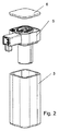
泡立てられたミルクの調製のための器具(ミルク泡立器具)1が、図1において全体として表される。図2は、その部品の分解図を示す。
An
器具1は、ミルク容器3、ミルク泡立ユニット5および蓋6を備える。
ミルク容器3は断熱目的のために、表された実施の形態において二重壁態様で設計されるが、一重壁設計も考えられ得る。それは透明か、またはミルクの液位をチェックするために視界窓を含むことができる。
The
The
ミルク容器3および蓋6を互いに一致させて、蓋6が、ミルク容器3上に、それの間に配置されるミルク泡立ユニット5なしに、直接配置することができるようにし、それよって、蓋を伴う充填されたミルク容器をたとえば冷蔵庫に入れることができる。ミルク容器および蓋は、さらに、単純な態様で清掃でき、たとえば食洗機対応態様で設計することができる。
The
ミルク泡立ユニット5の要素が図3における分解図で表される。下側メインハウジング部品11は、ギヤポンプに属する電気モータ13、および上側メインハウジング部品14を担持する。側方窓12は上側メインハウジング部品に形成される。
The elements of the
上側メインハウジング部品14は概ね円筒形の谷部を形成し、その中において、ギヤポンプのギヤ17が配置される。ギヤポンプのギヤ17は、電気モータ13に接続されるシャフト19を介して駆動される。封止部21は、谷部を底部に封止する。
The upper
ギヤ、シャフトおよび電気モータに加えて、ギヤポンプもそれ自体のハウジングを有することができ、またはそのようにメインハウジングもしくは他の部品内に、たとえばミルク泡立ユニットカバー16内に統合されることができる。表された実施の形態例では、ギヤ17を包含するポンプチャンバがアーチ形状部15(図12でさらに明瞭に見える)のために封止部21とミルク泡立ユニットカバー16との間において形成されるように、ミルク泡立ユニットカバー16は形状化される。
In addition to the gear, shaft and electric motor, the gear pump can also have its own housing, or can be so integrated in the main housing or other components, for example in the milk
バルブユニット20が、さらに、メインハウジング11、14上に固定される。
ミルク吸引管18(図3において表されず)が、器具1の組付けられた状態において、ギヤポンプの面から下方向に延在し、ミルク容器3内に、およびほとんどこのベースまで、突出する。
The
A milk suction tube 18 (not represented in FIG. 3) extends downward from the face of the gear pump in the assembled state of the
接続形状化部品22が、さらに、ギヤポンプの下に存在する。この部品は窓12を封止し、同時に、以下に記載され、一方ではメインハウジングに、および他方ではドッキング要素に固定される、ミルク泡立器の導管の接続のためのフィードスルーを形成する。
A
同様に図3で見えるのはスペーサ23およびモータ封止要素24である。
ドッキング要素はドッキング要素本体を含み、それはドッキング要素ハウジング26によって保護される。ドッキング要素本体は主本体25およびさらに以下に詳細に記載される補足部品27によって形成される。補足部品27が下方に突出するミルク泡沫出口28を含むことは、既に図3で理解され得る。
Also visible in FIG. 3 are the
The docking element includes a docking element body, which is protected by docking
図4は、封止部21によって規定された封止面より上にある面に沿って切断されたミルク泡立ユニット5の、上からの図を示す。平面図におけるライターラインは、さらに下を走る要素を表し、それら自体は見えない。
FIG. 4 shows a view from above of the
ギヤポンプは封止面より上に取付けられる。上側液体導管31はギヤポンプに至る。これは、封止21によって形成され、さらに、図5において明瞭に見えるダックビルバルブ42、41を介して、一方ではミルク吸引管18に、ならびに他方では湯導管および/または蒸気供給導管32に接続される。空気供給導管34は、上側液体導管に、つまりギヤポンプに入口側で、同様に、封止によって形成されるダックビルバルブ43を介して、接続される。
The gear pump is mounted above the sealing surface. The upper
選択された動作条件に依存して、既に泡立てられている、送給されたミルクのためのフィードスルー36がギヤポンプの背後に配置され、このフィードスルーを介して、このミルクは、再び封止面を通って下方向に進み、それは送出導管35を通ってドッキング要素に入る。
Depending on the operating conditions selected, a feed-through 36 for the supplied milk, which has already been whipped, is arranged behind the gear pump, via which the milk is again removed from the sealing surface. Through the
図6〜図8は、図6において水平面に沿って、図8において鉛直面に沿って、および図7において下からの図で切断されて表される上側メインハウジング部品14の図をさらに示す。
FIGS. 6-8 further show views of the upper
下側導管は接続形状化部品22の管によって形成され、それらは上側メインハウジング部品14の対応するチャネル内に置かれる。これらのチャネル、つまり湯および/または蒸気供給導管32のためのチャネル51、空気供給導管34のためのチャネル52、および送出導管35のためのチャネル53は、図7に従って下からの図において特に明瞭に見える。
The lower conduits are formed by the tubes of the
封止部21(図8)は、上側メインハウジング部品14とミルク泡立ユニットカバー(図8には示されない)との間において圧締めされる。ギヤ17を含むギヤポンプのポンプチャンバは、ミルク泡立ユニットカバー(図3;図12)におけるアーチ形状部15のため、ミルク泡立ユニットカバーと上側メインハウジング部品との間において形成される。
The seal 21 (FIG. 8) is clamped between the upper
さらなるオプション機能を図8に見ることができる。選択された動作条件に依存して既に泡立てられている、送給されたミルクのためのフィードスルー36は、スロットルの態様で狭くなる。背圧がこれによりギヤポンプにおいて生成され、その圧力のために、流量はそれ自体を調節する。この背圧は冷たいミルクの効率的な泡立てに寄与する。
Further optional features can be seen in FIG. The
図9は、バルブ要素20の図を示し、図10は、バルブユニットの分解図を示し、図11a〜図11cは上からの図においてバルブユニットを示し、図11aにおける線E−E、および図11aにおける線D−Dに沿って切断されている。
9 shows a view of the
図12は、ドッキング要素およびミルク吸引管なしに、バルブユニット20を伴うミルク泡立ユニットの図を上から示し、図13は、これが図12において線213を通る鉛直面に沿って切断されたものを示す。
FIG. 12 shows from above a view of the milk frothing unit with the
バルブユニット20は2つのバルブ要素を共通のバルブハウジング61において含む。各バルブ要素は、鉛直軸に沿って−選択された設置状況において−、封止要素63を担持し、軸に沿って可動である閉鎖要素62を含む。上方移動は、電磁石64により、電磁石(またはバルブハウジング)と固定リング66との間において応力をかけられたばね65の力に抗して行なわれる。閉鎖要素および封止要素によって上側で形成されるバルブ要素の頭部は、上側メインハウジング部品14において開口を通って突出する(図12および図13を参照)。閉じた状態では、それぞれの封止要素63の封止部分67はばねの力によって上側メインハウジング部品14の表面に対してそれぞれの開口の周囲に沿って押圧される。
The
両方のバルブで、バルブチャンバ71は、各場合において、上側メインハウジング部品14のそれぞれの壁と封止部68との間において形成される。封止要素63を伴う閉鎖要素が電磁石によって持上げられると、流入開口が形成され、その流入開口を通って、空気が外側からそれぞれのバルブチャンバ71内に流れることができ、およびこれから空気接続スタブまたはブランチ73を通って(共通の)空気供給導管に入ることができる。
With both valves, a
2つのバルブ要素を互いから独立して作動させることができ、各場合において個々にまたはともに開くことができる。これにより、異なる開弁状態を生じさせることができる。全体として、4つの開弁状態が、バルブ要素のどちらの1つだけが開いており他方は閉じていること、両方が開いていること、または両方が閉じていることによる結果、生じる。 The two valve elements can be operated independently of each other and can be opened individually or together in each case. As a result, different valve opening states can be generated. Overall, four open states result from having only one of the valve elements open and the other closed, both open, or both closed.
実施の形態では、バルブ要素および/またはそれぞれ形成された流入開口のサイズが異なるように大きな程度に選択されること、および/またはバルブ要素の1つによって入れられる空気が他のバルブ要素によって入れられる空気よりも著しく大きな流動抵抗を受けることも意味があり得る。4つの異なる規定された開口条件はそのとき定量的に異なる。たとえば、バルブ要素の1つの流入開口は、他方のバルブ要素の流入開口の2倍のサイズであり得、状態「0」(エアバルブは完全に閉じられる)、「1/3」(より小さなバルブ要素は開いている)、「2/3」(より大きなバルブ要素は開いている)、および「1」(両方のバルブ要素が開いている)を選択することができる。 In embodiments, the size of the valve elements and / or the respectively formed inlet openings is selected to a large extent to be different, and / or the air taken in by one of the valve elements is taken in by the other valve element. It may also make sense to experience significantly greater flow resistance than air. The four different defined opening conditions are then quantitatively different. For example, one inlet opening of one valve element may be twice as large as the inlet opening of the other valve element, with state "0" (air valve fully closed), "1/3" (smaller valve element). Is open), "2/3" (larger valve element is open), and "1" (both valve elements are open).
空気流調節要素、たとえば3/2ウェイバルブ(図示せず)などの、それによってバルブチャンバ71と混合ノズルとの間の通路またはバルブチャンバとギヤポンプの入口との間の通路を開くことができ、それぞれの他方の通路は閉じることができる空気流調節要素を、混合ノズルまたはギヤポンプは空気を供給されることになっているかどうかを調節するために、空気流方向においてバルブユニットの下流に接続される態様において配置することができる。しかしながら、そのような空気流調節要素は取り除くことができ、そのとき、その調節は、それぞれのバルブ要素によって、これらが、出口側での真空のためにのみ開き、この態様において、必要とされないそれぞれの通路内への泡立てられたミルクの逆流を防止することにより、自動的に行なわれる。
An airflow regulating element, such as a 3 / 2-way valve (not shown), whereby the passage between the
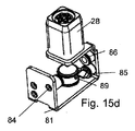
ドッキング要素の動作の構造および態様は、図14a〜図18cにより以下に記載される。図14aおよび図14bは、それぞれドッキング要素の斜め上および斜め下からの図を示す。図15aおよび図15bは補足部品27を展開状態において、ならびに図15cおよび図15dは折畳まれた状態において示す。図16aおよび図16bは主本体25を示す。図17a、図17bおよび図17cは、図17dにおいて面A−A、面B−Bおよび面C−Cに沿って切断されたドッキング要素を示す。図18aは、上から器具の図を示し、図18bおよび図18cは、図18aにおいて面A−Aおよび面B−Bに沿ってそれぞれ切断された器具の断面図の断面を示す。
The structure and aspects of the operation of the docking element are described below with reference to FIGS. 14a to 18c. 14a and 14b show views of the docking element from obliquely above and from below, respectively. 15a and 15b show the
図14aおよび図15cにおいてたとえば前部にある表側端部は、動作でコーヒーマシンに結合され、一方、対向する端部はミルク泡立ユニット5に結合され得る。
The front end, for example at the front in FIGS. 14 a and 15 c, can be connected in operation to a coffee machine, while the opposite end can be connected to the
主本体25は、全体として好適で耐熱性のあるプラスチックの形状化された本体として設計され、たとえば射出成形された部品として製造されることができる。補足部品27は、たとえばシリコーンから製造される。それは1片のものであり、全体として一体的にその上に形成される機能要素を伴う広範囲にわたる(シート状の)態様において設計される。広範囲なセクションの全体は、ここでは「ベース」として示される。連続的開口および溝状の凹部によって形成され、主本体25のまわりにおいて自由な折曲げを可能にするジョイント81が、広範囲なセクション80間において形成される。溝間の広範囲なセクション80の寸法は主本体の寸法に一致させる。
The
ミルク泡沫出口28とは別に、補足部品27の機能要素は、フィードスルー82〜86および混合ノズル要素89によって形成される。
Apart from the
主本体25はフィードスルー導管96を形成し、それは、コーヒーマシン側の端部から対向する端部へと通過し、清掃水(冷たいか、またはコーヒーマシンによって加熱された)または清浄蒸気のためのものであり、必要な場合、前記水または蒸気はフィードスルー導管96から湯および/または蒸気供給導管32内に進み、およびこれから、清掃されるべき要素、特にギヤポンプ内に進む。補足部品のフィードスルー86、84は、フィードスルー導管96に対して、各場合において、コーヒーマシン側およびミルク泡立器側に割当てられる。
The
蒸気接続部(蒸気がそれを通ってコーヒーマシンから混合ノズル内に入る)も形成される。蒸気接続部は、補足部品27の割当てられたバルブ87とともにフィードスルー85によって形成され、前記フィードスルーは、主本体25の蒸気接続開口95内に突出する。
A steam connection is also formed through which steam enters the mixing nozzle from the coffee machine. The steam connection is formed by a
ミルク泡立器側において、空気およびミルクの供給のために設けられ、補足部品の対応するフィードスルー82、83がその中へと突出する開口92、93が、各場合において主本体に形成される。空気フィードスルー82は割当てられたバルブ88を設けられ、これはちょうど蒸気バルブ87のようにダックビルバルブとして設計され、補足部品27の残りの部分と一体のものである。
On the milk frother side,
混合ノズルについて、主本体25は、混合ノズル開口99を含み、混合ノズル要素89はその中へと突出する。ミルク泡沫出口継続部91、およびこれを取り囲む位置決めリング94が、さらに、下側に形成され、補足部品の対応する構造90と協働する。
For the mixing nozzle, the
混合ノズルは、混合ノズル要素と主本体25の対応して形状化されたチャンバとの間に形成される。
The mixing nozzle is formed between the mixing nozzle element and a correspondingly shaped chamber of the
バルブ87を介して、蒸気接続部を介して供給される蒸気は、混合ノズルチャンバ97に入り、それは、たとえば図17cにおいて特に十分に見ることができる。真空が混合ノズルチャンバ97において蒸気の流れにより形成され、その真空によって、空気およびミルクが、それぞれのフィードスルー82、83(図17b、図18b)を介して吸引される。ミルク泡沫は混合ノズルチャンバにおいて生じて、下方向に、ミルク泡沫出口28を通って進み、準備ができて待機する飲料容器に入る。泡立てられたミルクは、蒸気によって放出された凝縮熱により暖かい。
Via the
蒸気が通って高速で出る小さなノズル開口のため、混合ノズルはしたがって、真空がノズル効果により形成されるように、設計される。これはさらに、たとえミルクがギヤポンプのため積極的に送給される場合であっても、ミルク導管からのミルクの移送を支援する。 Due to the small nozzle openings through which the steam exits at high speed, the mixing nozzle is therefore designed such that a vacuum is created by the nozzle effect. This further assists in the transfer of milk from the milk conduit, even if milk is actively pumped for the gear pump.
常圧またはわずかな過剰圧力が混合ノズルチャンバ97の内側において優勢である場合、ダックビルバルブ87、88は閉じられる。しかしながら、対照的に、−蒸気が流れ込むとすぐに−真空がベルヌーイ効果および/またはインパルス伝送のために優勢である場合には、それらは両方とも自動的に開く。
If normal pressure or a slight overpressure prevails inside the mixing
混合ノズルチャンバ内への空気の供給は、さらに、バルブユニットを通る代りに、たとえばダックビルバルブを介して、外部から直接行なうことができ、そのとき、互いから独立した2つの空気経路が、結果として、一方では混合ノズルチャンバのために、および他方ではギヤポンプのために生ずる。 The supply of air into the mixing nozzle chamber can furthermore be effected directly from the outside, for example via a duckbill valve, instead of through a valve unit, whereby two air paths independent of each other result in On the one hand for the mixing nozzle chamber and on the other hand for the gear pump.
混合ノズルチャンバ内への直接の空気の供給を伴うような設計も、実施の形態に対して選択することができ、たとえば、それによって、ここに記載される例とは異なり、電気的に動作される駆動部手段(電気的に動作されるポンプ)は存在せず、混合ノズルの吸引効果を利用しながら、単に蒸気に支援された態様において泡立てる。 A design with a direct supply of air into the mixing nozzle chamber may also be selected for the embodiment, for example, whereby it is electrically operated, unlike the example described here There is no drive means (electrically operated pump) present and only whip in a steam assisted manner, taking advantage of the suction effect of the mixing nozzle.
ドッキング要素は、ミルク泡沫出口28がホット飲料のための出口に接近してあり得るように、設計される。この目的のために、それは、飲料調製機の対応する面に結合された端面29の直接近くにおいて配置される。先に論じられたように、その距離は2.5cm以下であり、好ましくはそれよりさらに少ない。距離は、通常のように、端面によって規定される(鉛直)面に垂直に、この面とミルク泡沫出口から出る出口開口の中心点との間において測定される距離として、測定される。
The docking element is designed such that the
さらなるオプション機能が、図17cにおいて特に明らかである。‐一般的に泡立てられた‐ミルクが下方向に流れる出口チャンバ86は、ミルク泡沫出口28においてテーパする。これは一方ではさらなる泡沫形成および泡沫均質化効果があり、他方ではミルクまたはミルク泡沫の流れをチャネルで運ぶ。
Further optional features are particularly evident in FIG. 17c. The
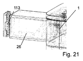
図19は、ミルク泡立器具1およびその上にミルク泡立器具1が結合されるコーヒーマシン101を伴う完全な飲料調製システム100の図を示す。図20は、出口フードが切断された態様において表された、この器具に関する詳細を示す。
FIG. 19 shows a diagram of a complete
コーヒーマシンは、コーヒーマシンに関してそれ自体公知であるように、水容器、水ポンプおよび湯沸し器を備える。コーヒー粉からの抽出により加熱水からコーヒーを調製するための淹出チャンバがさらに存在し、前記コーヒー粉末は、たとえば、調製の前に先にコーヒーマシンに挿入されたポーションカプセルにおいて設けられる。ポーションカプセルシステムに対する代替物として、コーヒーマシンは、さらに、コーヒーミルを含み、分配された態様においてコーヒー粉を挽き、それを淹出チャンバに供給する、いわゆる「豆からカップへの」コーヒーマシンとして設計することができる。さらなる代替物として、特にコーヒーマシンがピストンマシンとして設計される場合、つまり、淹出チャンバが固定部品と取外し可能なピストンとの間において形成される場合、さらに、コーヒー粉を、それが既に挽かれてはいるが緩い(圧縮されていない)状態にある態様でユーザによって淹出チャンバ内に入れられることを構想することができる。 The coffee machine comprises a water container, a water pump and a water heater, as is known per se for coffee machines. There is further a brewing chamber for preparing coffee from heated water by extraction from coffee grounds, said coffee grounds being provided, for example, in a portion capsule which has been inserted into a coffee machine prior to preparation. As an alternative to a potion capsule system, the coffee machine is further designed as a so-called "bean-to-cup" coffee machine that includes a coffee mill and grinds the coffee grounds in a dispensed manner and supplies it to the brewing chamber can do. As a further alternative, in particular if the coffee machine is designed as a piston machine, i.e. if the brewing chamber is formed between a fixed part and a removable piston, then the coffee grounds, which have already been ground It can be envisioned that the user enters the brewing chamber in a manner that is in a loose but uncompressed state.
コーヒーマシンは、さらに(コーヒーマシンの設計に依って、カプセルまたは緩い態様における)使用済コーヒー粉ポーションのための捕捉容器を含むことができる。 The coffee machine can further include a catch container for the used coffee ground portion (in a capsule or loose manner, depending on the design of the coffee machine).
飲料容器またはカップの配置のための配置プラットフォーム103が、コーヒーマシン上に形成される。これは、たとえば、捕捉皿が下に位置する格子により形成することができる。実施の形態では、配置プラットフォームは好適な態様では高さ調整可能であり得る。
A
コーヒー出口105は、淹出されたコーヒーがそれを介して流出し、その下にあるカップまたは容器に入るものであり、配置プラットフォーム103より上に位置する。この出口は、コーヒーマシンハウジングの一部を形成し、出口を少なくとも部分的に前部および側部に覆う出口フード108より下に位置する。
The
コーヒーマシン101は前部106を形成し、そこから、他のコーヒーマシンからそれ自体公知であるように、一方では、配置プラットフォーム103が突出し、他方では、これより上に、出口フード108が突出する。
The
ここで、ドッキングしたミルク泡立器具1が上に配置されるミルク泡立て器プラットフォーム107が、同様に前部から突出する。
Here, the
コーヒーマシン上へのドッキング要素の接続部のための接続位置110は、コーヒー出口105の近くにおいて、ここでは出口フードより下に位置する。この接続位置は、ドッキング要素の蒸気接続部上に結合するための蒸気送給位置111と、フィードスルー導管83上に結合するための湯および/または蒸気送給位置112とを含む。蒸気送給位置111ならびに湯および/または蒸気送給位置112は、必要に応じて、それぞれ湯沸し器から蒸気および湯を供給され、コーヒーマシンの内側におけるマルチウェイバルブは、加熱された液体または蒸気を、淹出モジュール、蒸気送給位置、または湯および/もしくは蒸気送給位置112に選択的に供給することができる。
The
接続位置はさらに好ましくは電気接点113を含み、それらは図21において概略的に表される。これらの電気接点113は飲料調製機側においてインターフェイスを形成し、結合オンのドッキング要素を与えられて、ドッキング要素を通って至る電気的なリードに接続されるかまたはこれらによって形成される、対応する電気的接続要素接点への電気的接続を形成する。これらの電気的なリードは、ミルク泡立器具の電気的に駆動される要素、具体的にはギヤポンプに、電気および制御信号を、場合に応じて供給する。
The connection locations further preferably include
それによって、ミルク泡立器具においてこれらの電気的に駆動される要素の制御を与えること(そのとき、この器具は必要な電子ユニットを設けられ、コーヒーマシンまたはミルク泡立器具の入力ユニットから制御信号を受信する)、およびコーヒーマシンそれ自体においてこれらの要素の制御を適応させることが可能である。後者の場合では、本質的に、制御の設定に従って電気的に駆動される要素を駆動する電流のみが、電気的なリードを通って導かれる。 Thereby providing control of these electrically driven elements in the milk frothing appliance (the appliance is then provided with the necessary electronic units and control signals from the input unit of the coffee machine or the milk frothing appliance) And control of these elements in the coffee machine itself can be accommodated. In the latter case, essentially only the current that drives the electrically driven element according to the control settings is conducted through the electrical leads.
ミルク泡立器具1のドッキングは側部から出口フード108上に対して行なわれ、具体的には、コーヒーマシンの前に、および出口フード108の横方向に、ミルク泡立器具が全体として配置されるように行なわれる。ドッキングは、たとえば前部106に沿って、組付けられたミルク泡立器具の、単純で、線形の、横方向移動により行なわれる。
The docking of the
図21(ミルク泡立器具1を結合解除された状態において示す)および特に図22(コーヒーマシンなしのミルク泡立器具)において見ることができるように、電気的なリードおよびドッキング要素側における対応する接点98はドッキング要素ハウジング26上に形成される。リードは、絶縁線もしくは撚線導体によって、またはプリント回路(回路基板もしくはフレックスプリント)の条導体などによって、形成することができる。
As can be seen in FIG. 21 (showing the
特にギヤポンプの制御は、ギヤ17の速度が調整可能である、つまり選択可能であるように構成される。これにより、ユーザは送給速度を制御することができ、−以下により詳細に記載される手順に従って−場合に応じて、冷たい泡立てられたミルクの調製を制御することができる。
In particular, the control of the gear pump is arranged such that the speed of the
図23は、ミルク泡立器具および飲料調製機(コーヒーマシン101)上へのその結合部の概観図を示す。空気供給路は図においては「L」として示される。文字Dは、蒸気のための導管を示し、Kは、ホット飲料のための導管を示し、Rは、清掃水または蒸気のための導管(オプション)を示し、Sは電気供給を示す。 FIG. 23 shows a schematic view of the milk frother and its connection on the beverage preparation machine (coffee machine 101). The air supply path is shown as "L" in the figure. The letter D indicates a conduit for steam, K indicates a conduit for hot beverage, R indicates a conduit for cleaning water or steam (optional), and S indicates an electrical supply.
ここで活性化部195はコーヒーマシン101の電子機器ユニット121の一部として表される。電子機器ユニット121は、たとえば測定値によりカプセルを認識するよう、および/またはたとえば対応するボタン、タッチスクリーンなどを伴う好適な操作要素を介してユーザ入力を受入れるよう、構成される。
Here, the
ここで、活性化部195は、それがギヤポンプ7およびバルブユニット20を活性化することができるように設計され、ギヤおよび/またはバルブユニットの動作パラメータを調節(閉ループ制御)することができる。バルブユニット20および/またはギヤポンプ7のための活性化信号は、直接、接続位置110を介して流れる。
Here, the
活性化部をコーヒーマシンにおいて完全にまたは部分的に組入れることと代替的に、活性化部195’が、さらに、完全にまたは部分的にミルク泡立器具の一部として存在することができる。この代替物は図20において破線態様で表される。そのとき、電気エネルギおよび場合に応じてデータ信号は、電子機器ユニットから活性化部195’に代替的なインターフェイス110’を介して送信することができる。 As an alternative to incorporating the activation part completely or partially in the coffee machine, the activation part 195 'can furthermore be present completely or partly as part of the milk frother. This alternative is represented in FIG. 20 in a dashed manner. Then, the electrical energy and optionally the data signal can be transmitted from the electronics unit to the activation unit 195 'via the alternative interface 110'.
混合ノズルは、全体として参照番号79によって示される。
ミルク泡立器具は以下のように動作することができる:
冷たい泡立てられたミルクの調製のために、バルブユニット20のバルブ要素の少なくとも1つが開いている間に、ギヤポンプが作動状態にセットされる。真空がこのポンプの効果のためにギヤポンプの入口側に形成され、この真空は、ミルク吸引管18および対応するダックビルバルブ42を通してミルクを、ならびにバルブユニット20および対応するダックビルバルブ43を通して空気を、吸引する。したがって、ミルク泡沫がギヤポンプにおいて生じ、フィードスルー36−その狭さが微細な空孔の泡沫の形成を促進する−、送出導管およびドッキング要素25を通って、ミルク泡沫出口28に達し、そこで分配供給され、一般的に、飲料容器200がプラットフォーム103上に配置される。
The mixing nozzle is indicated generally by the
The milk frother can operate as follows:
For the preparation of cold whipped milk, the gear pump is set to the operating state while at least one of the valve elements of the
ギヤポンプを介するミルク容器3からの概して冷たいミルクの吸引は、暖かい泡立てられたミルクの調製のためにも行なわれる。このギヤポンプは、混合ノズルにミルクを送給する。コーヒーマシンからの蒸気は、蒸気接続部を介してこのノズルに同時に供給される。既に上に説明されたように、蒸気は真空を形成し、それは、一方では、ミルクにさらなる吸引を及ぼし、ギヤポンプを通る送給を助け、他方では、同様の少なくとも部分的に開いているバルブ要素20を通して空気を吸引する。混合ノズルチャンバ97では、ミルクは蒸気と混合され、それによりそれを加熱し、空気が同時に混ぜ合せられ、したがって、小さな気泡が生じ、ミルク泡沫が生じる。暖かい、泡立てられたミルクはミルク泡沫出口を通して分配供給される。
The suction of generally cold milk from the
言及されたように、および状況に依存して、3/2ウェイバルブまたは別の手段によって、バルブ要素20を、ギヤポンプ7または混合ノズルチャンバ97に、それぞれ、冷たいミルク泡沫および暖かいミルク泡沫の生成のために、選択的に接続することができる。言及されたように、さらに、混合ノズルチャンバへの空気供給をバルブ要素20を介してではなく直接的な態様で行うことができ、その場合、空気の供給は、暖かいミルク泡沫を生成するときに別途の手段によって調節することができない。
As mentioned and depending on the situation, by means of a 3 / 2-way valve or another means, the
さらに、ユーザはさらに冷たいミルクを送給することしかできないことも構想され得る。この場合、ギヤポンプは駆動されるが、バルブ要素は閉じられたままであり、さらに、蒸気は供給されない。 Furthermore, it may be envisioned that the user can only deliver colder milk. In this case, the gear pump is driven, but the valve element remains closed and no steam is supplied.
さらに、ユーザが暖かいミルクを調製することができることも構想され得る。この場合、空気が通って混合チャンバに入ることができるバルブ要素は、閉じられる。万一混合ノズルチャンバのための別のバルブが与えられる場合(図において表された実施の形態とは異なる)、それぞれのバルブを閉鎖可能な態様で設計する可能性がさらにある。バルブの閉鎖は、たとえば機械的にユーザによって手動で構想することもできる。暖かいミルクの調製のために、ミルクがギヤポンプによってミルク容器3から送給され、空気も供給されずに、蒸気が混合ノズル79において同時に供給される。暖かいミルクが冷たいミルクの蒸気との混合により生じ、これが次いでミルク泡沫出口28を介して分配供給される。
It can further be envisioned that the user can prepare warm milk. In this case, the valve element through which air can enter the mixing chamber is closed. Should another valve be provided for the mixing nozzle chamber (different from the embodiment shown in the figures), it is furthermore possible to design each valve in a closable manner. The closing of the valve can also be envisaged manually by the user, for example mechanically. For the preparation of warm milk, milk is pumped out of the
現場清掃については、容器がミルク泡沫出口28より下に配置され、温水または蒸気がフィードスルー導管96ならびに湯および/または蒸気供給導管32を通して供給される。ギヤポンプは同時に動作状態にセットされる。
For on-site cleaning, the container is located below the
しかしながら、ミルク泡立器具は、さらに、それが取外された後、清浄が非常に簡単である。ミルク容器3および蓋6はいかなる問題もなく食洗機対応態様で設計することができる。ミルク泡立ユニット5は、同様に、単純であり、取り外され、清掃されることができ、封止部21がダックビルバルブ41、42、43と1つのピースとして設計されること、およびそれが面一態様で上側メインハウジング部品14の表面で終端することは、有用である。
However, the milk frother is also very easy to clean after it has been removed. The
最終的に、ドッキング要素は、ミルクと接触する部品(主本体25、補足部品27)が食洗機対応態様で設計されて、単純に取外すことができ、さらに単一の(正確な)構成のみにおいて再び組付けられて、単純である、という事実のため、清掃が簡単である。
Finally, the docking element is designed such that the parts that come in contact with the milk (
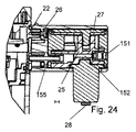
図24および図25は代替的実施の形態を表す。これは、上に記載される実施の形態とは異なり、ギヤポンプの空気供給路に向かっての−したがってたとえば記載されたタイプのたとえば空気供給導管34への、または直接ポンプチャンバへの−空気の供給は、ミルク泡立器具に属するバルブユニットによっては行なわれず、飲料調製機から来る態様で、行われる。飲料調製機は、この目的のために、たとえば電子的に調節されるバルブユニットを含む。このバルブユニットは、本質的に、上に記載されるミルク泡立器具のバルブユニットと同じ機能原理に基くことができる。それは、代替的に、たとえばそれが1つのバルブユニットのみを含むことにより、異なる機能原理を有することができる。 24 and 25 represent an alternative embodiment. This differs from the embodiment described above in that the supply of air towards the air supply of the gear pump-thus for example to the air supply conduit 34 of the type described, or directly to the pump chamber- Is not performed by the valve unit belonging to the milk frothing device, but in a manner coming from the beverage preparation machine. The beverage preparation machine includes a valve unit for this purpose, for example, which is electronically adjusted. This valve unit can be based essentially on the same functional principle as the valve unit of the milk frothing device described above. It can alternatively have a different functional principle, for example by it including only one valve unit.
この目的のために、ドッキング要素は、飲料調製機に向かって空気接続部151を含む。空気は、ここではドッキング要素を水平に通って通過する空気フィードスルー152を通ってミルク泡立ユニット内に達する。表された実施の形態例では、空気フィードスルーの或るセクションは、ドッキング要素ハウジング26の管部分155によって形成されるが、しかしながら、それは必須でない(空気フィードスルーに関して、定期的な清掃は、ミルクが流れる導管とは対照的に、必須ではない)。
For this purpose, the docking element includes an
電気接点が接点モジュール160によって形成されることができる可能性が、図25においてさらに示され、このモジュールはたとえば回路基板などを含み、ドッキング要素ハウジング26において好適な凹部内に挿入可能であり得る。
The possibility that electrical contacts can be formed by the
ミルク泡立ユニットにおいて配置されたバルブユニットは、図24および図25に従う実施の形態においてなしでなされる。 The valve unit arranged in the milk frothing unit is made without in the embodiment according to FIGS. 24 and 25.
多数のさらなる変形物が考えられる。既に論じられたオプションとは別に、さらに、(ポンプからの)冷たいミルク泡沫および(混合ノズルにおいて形成された)暖かいミルク泡沫のために導管を出口まで互いから分離して保持する可能性があり、つまり、そのとき、冷たいミルク泡沫は混合ノズルを介して導かれない。その場合、ミルク泡沫出口は、冷たいミルク泡沫および暖かいミルク泡沫のために、互いから分離した開口、たとえば互いに対して同心の開口を含むことができる。冷たいミルク泡沫および暖かいミルク泡沫のための、互いから完全に分離しているミルク泡沫出口も、考えられ得、上に論じられるミルク泡沫出口とホット飲料出口との間の最大の距離のためのオプションの条件は、この場合、たとえば暖かいミルク泡沫の放出に関して当てはまり、なぜならば、ホット飲料と混合されるのが多くの場合このミルク泡沫であるからである。 Numerous further variants are possible. Apart from the options already discussed, it is also possible to keep the conduits separate from each other up to the outlet for cold milk foam (from the pump) and warm milk foam (formed at the mixing nozzle), That is, then, the cold milk foam is not guided through the mixing nozzle. In that case, the milk foam outlet may comprise openings separate from each other, for example openings concentric with each other, for the cold milk foam and the warm milk foam. Milk foam outlets completely separate from each other for cold and warm milk foams are also conceivable and options for the maximum distance between the milk foam outlet and the hot beverage outlet discussed above The conditions in this case apply here, for example, with respect to the release of warm milk foam, since it is often this milk foam that is mixed with the hot beverage.
参照番号リスト:
1 ミルク泡立器具
3 ミルク容器
5 ミルク泡立ユニット
6 蓋
7 ギヤポンプ
11 下側メインハウジング部品
12 窓
13 電気モータ
14 上側メインハウジング部品
15 アーチ形状部(ミルク泡立ユニットカバーにおける)
16 ミルク泡立ユニットカバー
17 ギヤ
18 ミルク吸引管
19 シャフト
20 バルブユニット
21 封止部
22 接続形状化部
23 スペーサ
24 モータ封止要素
25 主本体(ドッキング要素の)
26 ドッキング要素ハウジング
27 補足部品
28 ミルク泡沫出口
29 端面
31 液体導管
32 湯および/または蒸気供給導管
34 空気供給導管
35 送出導管
36 フィードスルー
41 ダックビルバルブ
42 ダックビルバルブ
43 ダックビルバルブ
51 湯および/または蒸気供給導管のためのチャネル
52 空気供給導管のためのチャネル
53 送出導管のためのチャネル
61 バルブハウジング
62 閉鎖要素
63 封止要素
64 電磁石
65 ばね
66 固定リング
67 封止部分
68 封止部
71 バルブチャンバ
73 空気接続スタブ
79 混合ノズル
80 広範囲なセクション
81 ジョイント
82 空気フィードスルー
83 フィードスルー(ミルクのための)
84 湯または蒸気のためのフィードスルー
85 蒸気のためのフィードスルー
86 湯または蒸気のためのフィードスルー
87 ダックビルバルブ
88 ダックビルバルブ
89 混合ノズル要素
90 位置決めリングのためのリング(構造)
91 ミルク泡沫出口継続部
92 空気供給路のための開口
93 ミルク供給のための開口
94 位置決めリング
95 蒸気接続開口
96 フィードスルー導管
97 混合ノズルチャンバ
98 電気接点
99 混合ノズル開口
100 飲料調製システム
101 コーヒーマシン
103 配置プラットフォーム
105 コーヒー出口
106 前部
107 ミルク泡立器プラットフォーム
108 出口フード
110 接続位置
110’ 代替的インターフェイス
111 蒸気送給位置
112 湯および/または蒸気送給位置
113 電気接点
121 電子機器ユニット
151 空気接続部
152 空気フィードスルー
155 管部分
195 活性化部
195’ 代替的活性化部
200 飲料容器
Reference number list:
DESCRIPTION OF
16 Milk
26
84 Feed-through for hot water or
91 milk foam outlet continuation 92 opening for
Claims (15)
−前記飲料調製機によって送給される蒸気のための接続部と、
−前記飲料調製機によって供給され、前記駆動手段を動作させるための電流のためのインターフェイス(98)と、
−泡立てられたミルクのためのミルク泡沫出口(28)とを含む、泡立てられたミルクの調製のための器具(1)。 Apparatus (1) for the preparation of frothed milk, comprising a container (3) for receiving milk and electrically operated drive means for feeding and / or frothing milk. Characterized by a docking element for connection to a beverage preparation machine (101), said docking element comprising:
A connection for the steam delivered by the beverage preparation machine;
-An interface (98) supplied by the beverage preparation machine and for an electric current for operating the drive means;
A device (1) for the preparation of whipped milk, including a milk froth outlet (28) for whipped milk.
Applications Claiming Priority (3)
| Application Number | Priority Date | Filing Date | Title |
|---|---|---|---|
| EP14186265.6A EP3000363A1 (en) | 2014-09-24 | 2014-09-24 | Milk frothing device, beverage preparation system and machine for preparing beverages |
| EP14186265.6 | 2014-09-24 | ||
| PCT/EP2015/071795 WO2016046239A1 (en) | 2014-09-24 | 2015-09-22 | Milk foaming device, beverage preparation system and beverage preparation machine |
Publications (3)
| Publication Number | Publication Date |
|---|---|
| JP2017528266A JP2017528266A (en) | 2017-09-28 |
| JP2017528266A5 JP2017528266A5 (en) | 2018-11-01 |
| JP6625121B2 true JP6625121B2 (en) | 2019-12-25 |
Family
ID=51585052
Family Applications (1)
| Application Number | Title | Priority Date | Filing Date |
|---|---|---|---|
| JP2017516078A Active JP6625121B2 (en) | 2014-09-24 | 2015-09-22 | Milk frother, beverage preparation system, and beverage preparation machine |
Country Status (17)
| Country | Link |
|---|---|
| US (1) | US10638872B2 (en) |
| EP (2) | EP3000363A1 (en) |
| JP (1) | JP6625121B2 (en) |
| CN (1) | CN106998949B (en) |
| AU (1) | AU2015320872B2 (en) |
| BR (1) | BR112017006034B1 (en) |
| CA (1) | CA2960941A1 (en) |
| DK (1) | DK3079536T3 (en) |
| ES (1) | ES2660045T3 (en) |
| HK (1) | HK1225245B (en) |
| HU (1) | HUE038463T2 (en) |
| NO (1) | NO3079536T3 (en) |
| PL (1) | PL3079536T3 (en) |
| PT (1) | PT3079536T (en) |
| RU (1) | RU2702255C2 (en) |
| TR (1) | TR201802183T4 (en) |
| WO (1) | WO2016046239A1 (en) |
Families Citing this family (10)
| Publication number | Priority date | Publication date | Assignee | Title |
|---|---|---|---|---|
| ES2760956T3 (en) * | 2015-11-13 | 2020-05-18 | Nestle Sa | Foaming device |
| EP3205244A1 (en) | 2016-02-12 | 2017-08-16 | Qbo Coffee GmbH | Machine for making beverages |
| EP3205245A1 (en) | 2016-02-12 | 2017-08-16 | Qbo Coffee GmbH | Beverage preparation system |
| EP3210506A1 (en) * | 2016-02-29 | 2017-08-30 | Qbo Coffee GmbH | Milk frothing system and method of operation |
| EP3340195A1 (en) | 2016-12-23 | 2018-06-27 | Qbo Coffee GmbH | Method for operating a machine for making beverages, machine for making beverages and method for operating an operator panel |
| US10582754B2 (en) | 2017-03-08 | 2020-03-10 | Toly Management Ltd. | Cosmetic container |
| CA3084283A1 (en) * | 2017-12-08 | 2019-06-13 | Societe Des Produits Nestle S.A. | Device for producing milk and/or milk foam and associated system |
| JP1629472S (en) * | 2018-10-29 | 2019-04-15 | ||
| EP3987988A1 (en) | 2020-10-21 | 2022-04-27 | Tchibo GmbH | Beverage preparation machine with silicone drainage grille |
| CN114983233A (en) * | 2022-06-17 | 2022-09-02 | 江门市伊科迈特电子科技有限公司 | Novel bubble water machine |
Family Cites Families (28)
| Publication number | Priority date | Publication date | Assignee | Title |
|---|---|---|---|---|
| US5549036A (en) * | 1995-08-24 | 1996-08-27 | Hourizadeh; Richard | Cappuccino making apparatus |
| US7550169B2 (en) * | 2003-07-08 | 2009-06-23 | The Coca-Cola Company | System and method for producing foamed and steamed milk from milk concentrate |
| CH697020A5 (en) * | 2004-04-13 | 2008-03-31 | Steiner Ag Weggis | Method and apparatus for producing milk foam or warm milk drinks. |
| ITMI20040777A1 (en) * | 2004-04-21 | 2004-07-21 | De Longhi Spa | DEVICE AND PROCEDURE FOR THE PRODUCTION OF A MILK-BASED DRINK |
| KR20070042144A (en) * | 2004-07-09 | 2007-04-20 | 네스텍소시에테아노님 | System and device for preparing and delivering food products from a mixture made up of a food liquid and a diluent |
| DE202004014737U1 (en) * | 2004-09-22 | 2006-02-09 | Pav Patentverwertung Kg | Milk frother with bubble former |
| PL1658796T3 (en) * | 2004-11-18 | 2009-02-27 | Press Unique B V | Coffee machine and method for producing a hot drink |
| ATE389347T1 (en) * | 2005-02-08 | 2008-04-15 | Saeco Ipr Ltd | ARRANGEMENT FOR PRODUCING MILK FOAM AND HEATING MILK |
| ATE396636T1 (en) * | 2005-04-25 | 2008-06-15 | Nestec Sa | FOAMING DEVICE WITH FOAM FLOW CONTROL |
| ITMI20050880A1 (en) * | 2005-05-16 | 2006-11-17 | Saeco Internat Group S P A | STEAM UNIT WITH EXTERNAL ANCHORING INCLUDING A CARAFE FOR FOAMING MILK AND HEATING DRINKS FOR ESPRESSO DRINKING MACHINE |
| US7537138B2 (en) * | 2005-06-20 | 2009-05-26 | Nestec S.A. | Methods and systems for delivering foamed beverages from liquid concentrates |
| DE102007024443A1 (en) | 2007-05-25 | 2008-11-27 | BSH Bosch und Siemens Hausgeräte GmbH | Method for producing milk froth, involves distributing pressurized air stream in multiple partial streams and milk is displaced in movement vertical to flow direction of partial stream relative to partial stream |
| EP2156771A1 (en) * | 2008-08-19 | 2010-02-24 | Koninklijke Philips Electronics N.V. | Device and method for frothing a liquid |
| EP2220972A1 (en) | 2009-02-24 | 2010-08-25 | Jura Elektroapparate AG | Output device for milk and/or milk foam and a coffee machine with such an output device |
| DK2225976T3 (en) * | 2009-03-03 | 2012-11-26 | Delica Ag | Device for making milk foam |
| EP2245969A1 (en) | 2009-04-30 | 2010-11-03 | Jura Elektroapparate AG | Docking system for a milk container |
| EP2272408A1 (en) | 2009-07-08 | 2011-01-12 | Jura Elektroapparate AG | Drink preparation machine and method for cleaning same |
| DE102009041809B4 (en) * | 2009-09-18 | 2013-05-16 | Franke Kaffeemaschinen Ag | Apparatus and method for frothing a liquid food, in particular milk |
| ITFI20090248A1 (en) * | 2009-11-25 | 2011-05-26 | Saeco Ipr Ltd | "COFFEE MACHINE' " |
| IT1398056B1 (en) * | 2010-02-04 | 2013-02-07 | De Longhi Appliances Srl | AUTOMATIC COFFEE MACHINE |
| EP2386229A1 (en) * | 2010-05-10 | 2011-11-16 | Jura Elektroapparate AG | Milk cooler, drink preparation machine, combination of a milk cooler and a drink preparation device and method for obtaining an amount of milk |
| PT2571406E (en) | 2010-05-21 | 2014-06-02 | Nestec Sa | Remote controlled food processor |
| EP2478804A1 (en) * | 2011-01-21 | 2012-07-25 | Nestec S.A. | Milk frothing with pressurized gas |
| DE102011102734A1 (en) * | 2011-05-20 | 2012-11-22 | WMF Württembergische Metallwarenfabrik Aktiengesellschaft | Device for frothing milk, beverage preparation with this device and method for frothing milk |
| DE202012009074U1 (en) | 2012-09-21 | 2012-11-08 | Eugster/Frismag Ag | Device for the preparation of either cold or warm milk froth or delivery of either cold or warm milk |
| EP2877068B1 (en) * | 2012-10-05 | 2017-03-01 | Koninklijke Philips N.V. | Multi-functional jug and beverage producing machine using same |
| CN104000497B (en) * | 2014-04-11 | 2017-01-25 | 宁波全景电器技术有限公司 | Installation structure for water outlet nozzle of coffee machine |
| FR3056896B1 (en) * | 2016-09-30 | 2018-10-26 | Seb S.A. | DEVICE FOR PREPARING BEVERAGES WITH A MOBILE VAPOR NOZZLE |
-
2014
- 2014-09-24 EP EP14186265.6A patent/EP3000363A1/en not_active Withdrawn
-
2015
- 2015-09-22 PL PL15766549T patent/PL3079536T3/en unknown
- 2015-09-22 WO PCT/EP2015/071795 patent/WO2016046239A1/en active Application Filing
- 2015-09-22 AU AU2015320872A patent/AU2015320872B2/en active Active
- 2015-09-22 TR TR2018/02183T patent/TR201802183T4/en unknown
- 2015-09-22 US US15/513,203 patent/US10638872B2/en active Active
- 2015-09-22 PT PT157665498T patent/PT3079536T/en unknown
- 2015-09-22 NO NO15766549A patent/NO3079536T3/no unknown
- 2015-09-22 BR BR112017006034-5A patent/BR112017006034B1/en active IP Right Grant
- 2015-09-22 JP JP2017516078A patent/JP6625121B2/en active Active
- 2015-09-22 CN CN201580051027.6A patent/CN106998949B/en active Active
- 2015-09-22 HU HUE15766549A patent/HUE038463T2/en unknown
- 2015-09-22 DK DK15766549.8T patent/DK3079536T3/en active
- 2015-09-22 EP EP15766549.8A patent/EP3079536B1/en active Active
- 2015-09-22 RU RU2017112490A patent/RU2702255C2/en active
- 2015-09-22 ES ES15766549.8T patent/ES2660045T3/en active Active
- 2015-09-22 CA CA2960941A patent/CA2960941A1/en not_active Abandoned
-
2016
- 2016-11-30 HK HK16113652A patent/HK1225245B/en unknown
Also Published As
| Publication number | Publication date |
|---|---|
| CN106998949A (en) | 2017-08-01 |
| EP3079536B1 (en) | 2017-12-06 |
| RU2702255C2 (en) | 2019-10-07 |
| AU2015320872A1 (en) | 2017-05-18 |
| RU2017112490A3 (en) | 2019-04-18 |
| HUE038463T2 (en) | 2018-10-29 |
| PT3079536T (en) | 2018-03-02 |
| EP3079536A1 (en) | 2016-10-19 |
| HK1225245B (en) | 2017-09-08 |
| CA2960941A1 (en) | 2016-03-31 |
| NO3079536T3 (en) | 2018-05-05 |
| AU2015320872B2 (en) | 2020-02-20 |
| CN106998949B (en) | 2020-07-31 |
| RU2017112490A (en) | 2018-10-24 |
| PL3079536T3 (en) | 2018-06-29 |
| DK3079536T3 (en) | 2018-02-26 |
| WO2016046239A1 (en) | 2016-03-31 |
| TR201802183T4 (en) | 2018-03-21 |
| BR112017006034B1 (en) | 2022-01-25 |
| BR112017006034A2 (en) | 2017-12-12 |
| ES2660045T3 (en) | 2018-03-20 |
| JP2017528266A (en) | 2017-09-28 |
| EP3000363A1 (en) | 2016-03-30 |
| US10638872B2 (en) | 2020-05-05 |
| US20170303732A1 (en) | 2017-10-26 |
Similar Documents
| Publication | Publication Date | Title |
|---|---|---|
| JP6660379B2 (en) | Milk frother, beverage preparation system, and beverage preparation machine | |
| JP6625121B2 (en) | Milk frother, beverage preparation system, and beverage preparation machine | |
| JP6605592B2 (en) | Milk frothing equipment | |
| JP6720149B2 (en) | Milk frothing equipment | |
| EP2341805B1 (en) | Appliance for fine steam-frothing a milk-based liquid | |
| US8733234B2 (en) | Appliance for conditioning a milk-based liquid | |
| RU2526011C2 (en) | Milk foam production device | |
| CN111526764A (en) | Beverage machine with hot water and steam delivery and method of use |
Legal Events
| Date | Code | Title | Description |
|---|---|---|---|
| A521 | Request for written amendment filed |
Free format text: JAPANESE INTERMEDIATE CODE: A523 Effective date: 20180921 |
|
| A621 | Written request for application examination |
Free format text: JAPANESE INTERMEDIATE CODE: A621 Effective date: 20180921 |
|
| A977 | Report on retrieval |
Free format text: JAPANESE INTERMEDIATE CODE: A971007 Effective date: 20190925 |
|
| TRDD | Decision of grant or rejection written | ||
| A01 | Written decision to grant a patent or to grant a registration (utility model) |
Free format text: JAPANESE INTERMEDIATE CODE: A01 Effective date: 20191029 |
|
| A61 | First payment of annual fees (during grant procedure) |
Free format text: JAPANESE INTERMEDIATE CODE: A61 Effective date: 20191126 |
|
| R150 | Certificate of patent or registration of utility model |
Ref document number: 6625121 Country of ref document: JP Free format text: JAPANESE INTERMEDIATE CODE: R150 |
|
| R250 | Receipt of annual fees |
Free format text: JAPANESE INTERMEDIATE CODE: R250 |
|
| R250 | Receipt of annual fees |
Free format text: JAPANESE INTERMEDIATE CODE: R250 |