JP6624247B2 - Vehicle seat - Google Patents

Vehicle seat Download PDF

Info

Publication number
JP6624247B2
JP6624247B2 JP2018132007A JP2018132007A JP6624247B2 JP 6624247 B2 JP6624247 B2 JP 6624247B2 JP 2018132007 A JP2018132007 A JP 2018132007A JP 2018132007 A JP2018132007 A JP 2018132007A JP 6624247 B2 JP6624247 B2 JP 6624247B2
Authority
JP
Japan
Prior art keywords
air bag
air
vehicle seat
mounting portion
seat
Prior art date
Legal status (The legal status is an assumption and is not a legal conclusion. Google has not performed a legal analysis and makes no representation as to the accuracy of the status listed.)
Active
Application number
JP2018132007A
Other languages
Japanese (ja)
Other versions
JP2018158726A (en
JP2018158726A5 (en
Inventor
倉作 大森
倉作 大森
眞仁 菊池
眞仁 菊池
Current Assignee (The listed assignees may be inaccurate. Google has not performed a legal analysis and makes no representation or warranty as to the accuracy of the list.)
TS Tech Co Ltd
Original Assignee
TS Tech Co Ltd
Priority date (The priority date is an assumption and is not a legal conclusion. Google has not performed a legal analysis and makes no representation as to the accuracy of the date listed.)
Filing date
Publication date
Application filed by TS Tech Co Ltd filed Critical TS Tech Co Ltd
Priority to JP2018132007A priority Critical patent/JP6624247B2/en
Publication of JP2018158726A publication Critical patent/JP2018158726A/en
Publication of JP2018158726A5 publication Critical patent/JP2018158726A5/ja
Application granted granted Critical
Publication of JP6624247B2 publication Critical patent/JP6624247B2/en
Active legal-status Critical Current
Anticipated expiration legal-status Critical

Links

Images

Description

本発明は、膨張または収縮することで乗員のサポート位置を変更する空気袋を備えた乗物用シートに関する。 The present invention relates to a vehicle seat provided with an air bag that changes an occupant's support position by inflating or contracting .

従来より、シートの内部に設けられた空気袋の空気圧を調整することで、乗員の腰部のサポート位置を調整することができるサポート装置を備えた車両用のシートが知られている(特許文献1参照)。特許文献1のシートでは、空気袋に空気を供給するポンプがシートクッション部の下側に設けられている。   BACKGROUND ART Conventionally, there is known a vehicle seat provided with a support device capable of adjusting a support position of an occupant's waist by adjusting an air pressure of an air bag provided inside the seat (Patent Document 1). reference). In the seat of Patent Document 1, a pump for supplying air to the air bag is provided below the seat cushion.

特開2010−235021号公報JP 2010-235021 A

ところで、乗員のサポート位置を調整可能な乗物用シートにおいては、乗員を好適にサポートできることが望ましい。 By the way, in a vehicle seat in which the support position of the occupant can be adjusted, it is desirable that the occupant can be suitably supported .

そこで、本発明は、乗員を好適にサポートすることができる乗物用シートを提供することを目的とする。 Then, an object of this invention is to provide the vehicle seat which can support a passenger suitably .

前記した目的を達成するため、乗物用シートは、着座部およびシートバックを有するシート部と、前記シート部内に設けられ、膨張または収縮することで乗員のサポート位置を変更する空気袋と、を備えた乗物用シートであって、前記シート部は、左右のフレームを構成する長尺状の左右のサイドフレームを備え、前記空気袋は、プレート部材を介して前記サイドフレームに固定され、前記サイドフレームの長手方向に沿った端部に凹部が形成された第1空気袋を含み、前記第1空気袋は、前記プレート部材に固定される取付部を有し、前記取付部は、前記長手方向に離間して形成された第1取付部と第2取付部を有し、前記乗物用シートは、前記第1空気袋に連結され、前記第1空気袋へガスを供給するためのホースをさらに備え、前記凹部は、前記長手方向において前記第1空気袋と前記ホースとの連結部分と異なる位置に設けられており、前記第1空気袋と前記ホースとの連結部分は、前記長手方向において前記第1取付部と前記第2取付部の間に位置することを特徴とする。
前記した乗物用シートにおいて、前記第1空気袋は、前記取付部がクリップによって固定されている構成とすることができる。
前記した乗物用シートにおいて、前記凹部は、前記長手方向において前記第1取付部と前記第2取付部の間に設けられている構成とすることができる。
前記した乗物用シートにおいて、前記第1取付部と前記第2取付部は、前記第1空気袋の前記凹部が形成された側に形成されている構成とすることができる。
前記した乗物用シートにおいて、前記凹部は、前記取付部よりも前に設けられている構成とすることができる。
前記した乗物用シートにおいて、前記取付部は、前記第1空気袋の下端に形成されている取付部を含む構成とすることができる。
前記した乗物用シートは、前記左右のサイドフレームの間に配置された受圧部材を備え、前記凹部は、前記長手方向において前記受圧部材と重なる位置に設けられている構成とすることができる。
前記した乗物用シートにおいて、前記空気袋は、前記受圧部材に取り付けられた第2空気袋を含む構成とすることができる。
前記した乗物用シートにおいて、前記第1空気袋は、左右方向から見て、前記サイドフレームと重なるように配置されている構成とすることができる
た、乗物用シートは、着座部およびシートバックを有するシート部と、前記シート部内に設けられた乗員の腰部のサポート位置を調整可能なサポート装置とを備えた乗物用シートであって、前記着座部の左右のフレームを構成する左右の着座部サイドフレームと、左右方向に延びて前記左右の着座部サイドフレームを連結する連結部材と、前記サポート装置を構成し、膨張または収縮することで前記サポート位置を変更する空気袋と、前記空気袋にガスを供給するポンプと、前記ポンプを前記連結部材に取り付けるための左右方向に延びるブラケットと、を備え、前記ブラケットは、下から上に向けて凹む形状をなす凹部を有し、前記ポンプは、中心軸線が前記ブラケットの凹部の下端よりも上に入り込んだ状態で前記ブラケットに取り付けられ、前記連結部材は、下から上に向けて凹む形状をなす凹部を有し、前記ブラケットは、前記連結部材の凹部に入り込んだ状態で前記連結部材に取り付けられていることを特徴とする。
In order to achieve the object described above, the vehicle seat includes a seat portion having a seating portion and a seat back, and an air bag provided in the seat portion and changing a support position of the occupant by expanding or contracting. Vehicle seat, wherein the seat portion includes left and right long side frames constituting left and right frames, the air bag is fixed to the side frame via a plate member , the side frame look including a first air bladder having a concave portion formed at an end portion along the longitudinal direction of the first air bag has a mounting portion fixed to the plate member, the mounting portion, the longitudinal The vehicle seat further includes a hose connected to the first air bladder and configured to supply gas to the first air bladder. Equipped, said concave Is provided at a position different from a connecting portion between the first air bag and the hose in the longitudinal direction, and a connecting portion between the first air bag and the hose is provided in the first mounting portion in the longitudinal direction. And the second mounting portion .
In the sheet for the above-described vehicle, the first air bag, it can be configured to pre-Symbol mounting portion is fixed by a clip.
In the sheet for the above-described vehicle, before Symbol recess may be configured to in the longitudinal direction is provided between the second mounting portion and the first mounting portion.
In the vehicle seat described above, the first attachment portion and the second attachment portion may be configured to be formed on a side of the first air bladder where the concave portion is formed.
In the vehicle seat described above, the recess may be provided before the mounting portion.
In the vehicle seat described above, the mounting portion may include a mounting portion formed at a lower end of the first air bladder.
The vehicle seat may include a pressure receiving member disposed between the left and right side frames, and the recess may be provided at a position overlapping the pressure receiving member in the longitudinal direction.
In the vehicle seat described above, the air bladder may include a second air bladder attached to the pressure receiving member.
In the vehicle seat described above, the first air bladder may be configured to be disposed so as to overlap with the side frame when viewed from the left-right direction .
Also, the vehicle seat includes a seat portion and a seat portion having a seat back, a vehicle seat having an adjustable support device supporting position of the occupant's lumbar region provided in the seat portion, wherein The left and right seating part side frames forming the left and right frames of the seating part, the connecting member extending in the left-right direction and connecting the left and right seating part side frames, and the support device are configured, and the support device is expanded or contracted. An air bag for changing a support position, a pump for supplying gas to the air bag, and a bracket extending in the left-right direction for attaching the pump to the connecting member, wherein the bracket is arranged from bottom to top. The pump has a concave portion having a concave shape, and the pump is attached to the bracket in a state where a center axis line extends above a lower end of the concave portion of the bracket. Is, the connecting member has a recess in the shape recessed from bottom to top, the bracket is characterized in that mounted on the connecting member in a state of entering into the recess of the connecting member.

このような構成によれば、連結部材やブラケットが全体として凹凸形状をなすことになるので、連結部材やブラケットの剛性を向上させることができる。これにより、ポンプの取付剛性を向上させることができる。   According to such a configuration, since the connecting member and the bracket have an uneven shape as a whole, the rigidity of the connecting member and the bracket can be improved. Thereby, the mounting rigidity of the pump can be improved.

前記した乗物用シートにおいて、前記ポンプは、ガスの送出口が前記ブラケットの凹部の下端よりも上に入り込んだ状態で配置されている構成とすることができる。
前記した乗物用シートにおいて、前記ポンプは、全体が前記ブラケットの凹部の下端よりも上に入り込んだ状態で配置されている構成とすることができる。
In the above-described vehicle seat, the pump may be configured such that the gas outlet is located above the lower end of the recess of the bracket.
In the vehicle seat described above, the pump may be arranged so as to be entirely inserted above the lower end of the concave portion of the bracket.

前記した乗物用シートにおいて、前記ブラケットは、当該ブラケットの凹部の裏側に形成される凸部が、前記連結部材の凹部に入り込んだ状態で前記連結部材に取り付けられ、前記ブラケットの凹部の底壁の左右方向の長さが、前記ブラケットの凹部の開口縁から左右方向外側に延びる壁の左右方向の長さよりも長い構成とすることができる。
前記した乗物用シートにおいて、前記ポンプは、前記連結部材の凹部を形成する前後方向に対向した一対の壁の間に配置されている構成とすることができる。
In the vehicle seat described above, the bracket is attached to the connecting member in a state where a convex portion formed on the back side of the concave portion of the bracket is inserted into the concave portion of the connecting member, and the bottom wall of the concave portion of the bracket is The length in the left-right direction may be longer than the length in the left-right direction of the wall extending outward in the left-right direction from the opening edge of the recess of the bracket.
In the vehicle seat described above, the pump may be configured to be disposed between a pair of walls facing each other in the front-rear direction forming a recess of the connecting member.

前記した乗物用シートは、前記左右の着座部サイドフレームの間に設けられたサブマリン規制部材を備え、前記サブマリン規制部材は、前記連結部材の凹部に入り込んだ状態で配置されている構成とすることができる。
前記した乗物用シートにおいて、前記ポンプは、前記サブマリン規制部材よりも前方に配置されている構成とすることができる。
前記した乗物用シートにおいて、前記ポンプは、前記サブマリン規制部材の左右方向に延びる部分と平行に配置されている構成とすることができる。
The vehicle seat may include a submarine regulating member provided between the left and right seating side frames, and the submarine regulating member may be configured to be disposed in a recessed portion of the connecting member. Can be.
In the vehicle seat described above, the pump may be arranged forward of the submarine regulating member.
In the vehicle seat described above, the pump may be configured to be arranged in parallel with a portion of the submarine regulating member extending in the left-right direction.

前記した乗物用シートにおいて、前記ポンプは、中心軸線が前記連結部材の凹部に入り込んだ状態で配置されている構成とすることができる。
前記した乗物用シートにおいて、前記ポンプは、ガスの送出口が設けられていない長手方向の一端部が前記左右の着座部サイドフレームの間の左右方向の端寄りに配置され、ガスの送出口が設けられた長手方向の他端部が前記左右の着座部サイドフレームの間の左右方向中央寄りに配置されるように設けられている構成とすることができる。
In the vehicle seat described above, the pump may be configured such that the center axis is disposed so as to enter the recess of the connecting member.
In the vehicle seat described above, the pump has one end in the longitudinal direction where a gas outlet is not provided, which is disposed near a left-right end between the left and right seating side frames, and a gas outlet is provided. The other end in the longitudinal direction provided may be provided so as to be disposed closer to the center in the left-right direction between the left and right seating portion side frames.

本発明によれば、乗員を好適にサポートすることができるAccording to the present invention, an occupant can be favorably supported .

本発明の実施形態に係る車両用シートの斜視図である。1 is a perspective view of a vehicle seat according to an embodiment of the present invention. サポート装置の概略図である。It is a schematic diagram of a support device. 図1のA−A断面図である。It is AA sectional drawing of FIG. パンフレームを下から見た図である。It is the figure which looked at the bread frame from the bottom. 図4のB−B断面図である。FIG. 5 is a sectional view taken along line BB of FIG. 4. シートバックフレームを前から見た図(a)と、(a)のC−C断面図(b)である。It is the figure (a) which looked at the seat back frame from the front, and the CC sectional view (b) of (a). 受圧部材とシートバックサイドフレームを右斜め前から見た斜視図である。It is the perspective view which looked at the pressure receiving member and the seat back side frame from diagonally right front. 受圧部材とシートバックサイドフレームを後から見た図である。It is the figure which looked at the pressure receiving member and the seat back side frame from back. 図7のD−D断面図である。It is DD sectional drawing of FIG. 左のシートバックサイドフレームとサイドブラケットを左右方向内側から見た図である。It is the figure which looked at the left seat back side frame and the side bracket from the left-right direction inside. シートバックフレーム、乗員の後方に配置される空気袋および受圧部材を前から見た図である。It is the figure which looked at the seat back frame, the air bag arrange | positioned behind a passenger | crew, and the pressure receiving member from the front. 前側空気袋の正面図(a)と、後側空気袋の正面図(b)である。It is the front view (a) of a front air bag, and the front view (b) of a rear air bag. 前側空気袋が膨張した状態を示す斜視図である。It is a perspective view showing the state where the front air bag was inflated. 左のシートバックサイドフレームと空気袋を左右方向内側から見た図である。It is the figure which looked at the left seat back side frame and the air bag from the left-right direction inside. 左のシートバックサイドフレーム、サイドブラケット、プレート部材および空気袋の斜視図(a)と、プレート部材の爪部を示す図(b),(c)である。FIG. 3A is a perspective view of a left seat back side frame, a side bracket, a plate member, and an air bag, and FIGS. 2B and 2C show claw portions of the plate member. 乗員の左方に配置される空気袋とプレート部材を上から見た図であり、収縮した状態を示す図(a)と、膨張した状態を示す図(b)である。It is the figure which looked at the air bladder and plate member arrange | positioned to the occupant's left from above, and is the figure (a) which shows a contracted state, and the figure (b) which shows an expanded state.

次に、本発明の一実施形態について、適宜図面を参照しながら詳細に説明する。なお、本発明において、前後、左右および上下は、シートに座る乗員を基準とする。   Next, an embodiment of the present invention will be described in detail with reference to the drawings as appropriate. In the present invention, front, rear, left, right and up and down are based on an occupant sitting in a seat.

<車両用シートの概略構成>
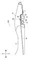
図1に示すように、乗物用シートの一例としての車両用シート1は、シート部2と、シート部2内に設けられたサポート装置3(図2参照)とを主に備えている。そして、シート部2は、乗員が着座する着座部4と、着座部4にリクライニング機構を介して固定されたシートバック5と、ヘッドレスト(図示省略)とを主に有している。
<Schematic configuration of vehicle seat>
As shown in FIG. 1, a vehicle seat 1 as an example of a vehicle seat mainly includes a seat portion 2 and a support device 3 (see FIG. 2) provided in the seat portion 2. The seat 2 mainly includes a seat 4 on which the occupant sits, a seat back 5 fixed to the seat 4 via a reclining mechanism, and a headrest (not shown).

着座部4およびシートバック5は、着座部フレーム40およびシートバックフレーム50の外側に、ウレタンフォームなどからなるクッション材(図示省略)と、合成皮革や布地などからなる表皮材(図示省略)を被せることで構成されている。また、図1および図2に示すように、サポート装置3は、4つの空気袋31A,31B,31L,31Rと、空気袋31A,31B,31L,31Rに空気(ガス)を供給するポンプ32と、空気袋31A,31B,31L,31Rの膨らみ量を調整する制御ユニット33と、可撓性を有するホース34〜37とを主に備えて構成されている。   The seat portion 4 and the seat back 5 cover a cushion material (not shown) made of urethane foam or the like and a skin material (not shown) made of synthetic leather, cloth, or the like on the outside of the seat portion frame 40 and the seat back frame 50. It is composed of As shown in FIGS. 1 and 2, the support device 3 includes four air bladders 31A, 31B, 31L, and 31R, and a pump 32 that supplies air (gas) to the air bladders 31A, 31B, 31L, and 31R. And a control unit 33 for adjusting the amount of inflation of the air bags 31A, 31B, 31L, 31R, and flexible hoses 34 to 37.

空気袋31A,31Bは、車両用シート1に着座した乗員の腰部を後方から支持する部材であり、左右のシートバックサイドフレーム51の間に配置されている。また、空気袋31L,31Rは、乗員の腰部を左方または右方から支持するサポート部材であり、それぞれ、左または右のシートバックサイドフレーム51の内側に配置されている。制御ユニット33は、左のシートバックサイドフレーム51の外側の面に取り付けられており、開閉可能なバルブユニットやリリーフバルブ、バルブユニットの開閉量を制御する制御基板など(いずれも図示省略)を有している。   The air bladders 31A and 31B are members that support the lumbar portion of the occupant sitting on the vehicle seat 1 from behind, and are disposed between the left and right seat back side frames 51. The air bladders 31L and 31R are support members for supporting the occupant's waist from the left or right, and are disposed inside the left or right seat back side frame 51, respectively. The control unit 33 is attached to the outer surface of the left seat back side frame 51, and includes a valve unit that can be opened and closed, a relief valve, a control board that controls the opening and closing amount of the valve unit, and the like (all not shown). are doing.

ホース34は、ポンプ32と制御ユニット33を接続し、ホース35は、空気袋31Aと制御ユニット33を接続し、ホース36は、空気袋31Bと制御ユニット33を接続している。また、ホース37は、一端が制御ユニット33に接続され、途中で分岐して、それぞれの端部が空気袋31Lまたは空気袋31Rに接続されている。これにより、本実施形態においては、空気袋31Aと、空気袋31Bと、空気袋31L,31Rの膨らみ量を個別に調整することができるようになっている。   The hose 34 connects the pump 32 and the control unit 33, the hose 35 connects the air bladder 31A and the control unit 33, and the hose 36 connects the air bladder 31B and the control unit 33. Further, the hose 37 has one end connected to the control unit 33, branches on the way, and each end is connected to the air bladder 31L or the air bladder 31R. Thus, in the present embodiment, the swelling amounts of the air bladder 31A, the air bladder 31B, and the air bladders 31L and 31R can be individually adjusted.

このサポート装置3は、通常時は、制御ユニット33のバルブユニットが閉じられている。そして、乗員がコントローラ(図示省略)を操作することで、バルブユニットが開き、ポンプ32から空気が供給されることで空気袋31A,31B,31L,31Rが膨張変形し、また、バルブユニットが開いた状態で空気袋31A,31B,31L,31Rに対し乗員から圧力がかかることで空気袋31A,31B,31L,31Rが収縮変形する。これにより、乗員の腰部のサポート位置を変更(調整)することができるようになっている。なお、ポンプ32から制御ユニット33に供給された余分な空気や、空気袋31A,31B,31L,31Rから押し出された空気は、制御ユニット33のリリーフバルブによって外部に排気される。   In the support device 3, the valve unit of the control unit 33 is normally closed. When the occupant operates a controller (not shown), the valve unit is opened, and air is supplied from the pump 32, whereby the air bags 31A, 31B, 31L, 31R are inflated and deformed, and the valve unit is opened. When the occupant applies pressure to the air bags 31A, 31B, 31L, and 31R in the retracted state, the air bags 31A, 31B, 31L, and 31R contract and deform. As a result, the support position of the occupant's waist can be changed (adjusted). The excess air supplied from the pump 32 to the control unit 33 and the air pushed out from the air bags 31A, 31B, 31L, 31R are exhausted outside by the relief valve of the control unit 33.

<着座部の詳細構成>
図1に示すように、着座部フレーム40は、着座部4の左右のフレームを構成する左右の着座部サイドフレーム41と、連結部材としてのパンフレーム42と、サブマリン規制部材としてのサブマリンパイプ43(図3,4参照)と、リア連結パイプ44と、ブラケットとしてのポンプ取付ブラケット6(図3〜5参照)とを主に備えている。各着座部サイドフレーム41およびパンフレーム42は、それぞれ、金属板をプレス加工するなどして形成されている。
<Detailed configuration of seating part>
As shown in FIG. 1, the seat frame 40 includes left and right seat side frames 41 constituting left and right frames of the seat 4, a pan frame 42 as a connecting member, and a submarine pipe 43 as a submarine regulating member. 3 and 4), a rear connection pipe 44, and a pump mounting bracket 6 (see FIGS. 3 to 5) as a bracket. Each of the seat side frame 41 and the pan frame 42 is formed by pressing a metal plate.

パンフレーム42は、左右方向に延びて左右の着座部サイドフレーム41の前部を連結する部材であり、図3に示すように、その下面に下から上に向けて凹む形状をなす凹部42Aが形成されている。また、パンフレーム42の上面(凹部42Aの底に相当する部分)には、フック部42Hが形成されている。パンフレーム42に形成されたフック部42Hとリア連結パイプ44との間には、着座部4に着座する乗員を支持する乗員支持部材としてのシートスプリング45が張設されている(図1も参照)。   The pan frame 42 is a member that extends in the left-right direction and connects the front portions of the left and right seating portion side frames 41. As shown in FIG. 3, a concave portion 42A having a shape recessed upward from below is formed on the lower surface thereof. Is formed. A hook portion 42H is formed on the upper surface of the pan frame 42 (a portion corresponding to the bottom of the concave portion 42A). Between the hook portion 42H formed on the pan frame 42 and the rear connection pipe 44, a seat spring 45 as an occupant support member for supporting an occupant sitting on the seat portion 4 is stretched (see also FIG. 1). ).

サブマリンパイプ43およびリア連結パイプ44(図1参照)は、左右方向に延びる金属製のパイプであり、左右の着座部サイドフレーム41の間にそれぞれ設けられている。サブマリンパイプ43は、車両の衝突時(前突時)に乗員が着座部4に沈み込みながら前方へ移動しようとするいわゆるサブマリン現象を規制する部材であり、左右の着座部サイドフレーム41の前部を連結するように設けられている。このサブマリンパイプ43は、パンフレーム42の下、より詳細には、パンフレーム42に形成された凹部42A内の後寄りにおいて当該凹部42Aに入り込んだ状態で配置されている。図1に示すように、リア連結パイプ44は、左右の着座部サイドフレーム41の後部を連結するように設けられている。   The submarine pipe 43 and the rear connection pipe 44 (see FIG. 1) are metal pipes extending in the left-right direction, and are provided between the left and right seating side frames 41, respectively. The submarine pipe 43 is a member that regulates a so-called submarine phenomenon in which an occupant tries to move forward while sinking into the seat portion 4 at the time of a vehicle collision (front collision), and is a front portion of the left and right seat portion side frames 41. Are connected to each other. The submarine pipe 43 is disposed below the pan frame 42, more specifically, at a position rearward in the concave portion 42 A formed in the pan frame 42, so as to enter the concave portion 42 A. As shown in FIG. 1, the rear connection pipe 44 is provided so as to connect the rear portions of the left and right seating side frames 41.

図5に示すように、ポンプ取付ブラケット6は、左右方向に延びる板状の部材であり、下から上に向けて凹む形状をなす凹部6Aが形成されている。このポンプ取付ブラケット6は、当該ポンプ取付ブラケット6の凹部6Aの裏側に形成される凸部6Bが、図3に示すように、パンフレーム42の凹部42Aに入り込んだ状態でパンフレーム42に取り付けられている。
ポンプ32は、クッション性を有する革袋61(図4参照)に入れられ、ポンプ取付ブラケット6の凹部6Aに入り込んだ状態でポンプ取付ブラケット6に取り付けられている(図5も参照)。これにより、ポンプ32は、パンフレーム42の凹部42Aに入り込んだ状態で、パンフレーム42の下に配置されている。
As shown in FIG. 5, the pump mounting bracket 6 is a plate-like member extending in the left-right direction, and has a recess 6A that is recessed upward from below. The pump mounting bracket 6 is attached to the pan frame 42 in a state where the convex portion 6B formed on the back side of the concave portion 6A of the pump mounting bracket 6 enters the concave portion 42A of the pan frame 42 as shown in FIG. ing.
The pump 32 is placed in a leather bag 61 having cushioning properties (see FIG. 4) and attached to the pump mounting bracket 6 in a state of being inserted into the recess 6A of the pump mounting bracket 6 (see also FIG. 5). Thus, the pump 32 is disposed below the pan frame 42 in a state where the pump 32 enters the concave portion 42A of the pan frame 42.

また、ポンプ32は、パンフレーム42の凹部42A内の前寄り、言い換えると、凹部42A内に配置されたサブマリンパイプ43よりも前方に配置されている。詳細には、ポンプ32とサブマリンパイプ43は、パンフレーム42の凹部42Aに入り込んだ状態で前後方向に並べて、すなわち、前後方向から見て少なくとも一部同士が重なり合うように配置されている。   Further, the pump 32 is disposed forward of the concave portion 42A of the pan frame 42, in other words, forward of the submarine pipe 43 disposed in the concave portion 42A. Specifically, the pump 32 and the submarine pipe 43 are arranged in the front-rear direction while being inserted into the concave portion 42A of the pan frame 42, that is, are arranged so that at least a part thereof overlaps when viewed from the front-rear direction.

さらに、ポンプ32は、図4に示すように、その長手方向(円筒の軸線が延びる方向)が左右方向を向くようにして、左右の着座部サイドフレーム41の間の左側に寄せられた状態で、サブマリンパイプ43の左右方向中央部分と略平行に配置されている。ポンプ32は、空気の出口である送出口32Aを有しており、この送出口32Aが左右の着座部サイドフレーム41の間の左右方向中央寄りに位置するような向きに取り付けられている。すなわち、ポンプ32は、送出口32Aが設けられていない長手方向の一端部(左端部)が左右の着座部サイドフレーム41の間の左右方向の端寄りに配置され(左の着座部サイドフレーム41に対面して配置され)、送出口32Aが設けられた長手方向の他端部(右端部)が左右の着座部サイドフレーム41の間の左右方向中央寄りに配置されるように設けられている。   Further, as shown in FIG. 4, the pump 32 is shifted to the left between the left and right seating part side frames 41 such that the longitudinal direction (the direction in which the axis of the cylinder extends) is directed to the left and right. The submarine pipe 43 is disposed substantially in parallel with the central portion in the left-right direction. The pump 32 has an air outlet 32A which is an air outlet, and is mounted so that the air outlet 32A is located closer to the center in the left-right direction between the left and right seating side frames 41. That is, in the pump 32, one end (left end) in the longitudinal direction where the outlet 32 </ b> A is not provided is arranged near the left-right end between the left and right seat side frames 41 (the left seat side frame 41). And the other end (right end) in the longitudinal direction provided with the outlet 32A is provided near the center in the left-right direction between the left and right seating side frames 41. .

パンフレーム42やシートスプリング45などの下では、ポンプ32の送出口32Aに接続されたホース34や、コントローラと制御ユニット33を接続するハーネス38などが、結束バンド91によって数箇所でポンプ取付ブラケット6やシートスプリング45などに留められており、垂れ下がったり、振動や空気が供給されるときの圧力などで動いたりしないようになっている。   Under the pan frame 42 and the seat spring 45, the hose 34 connected to the outlet 32A of the pump 32, the harness 38 connecting the controller and the control unit 33, and the like are connected to the pump mounting bracket 6 at several places by a binding band 91. And is secured to the seat spring 45 so that it does not hang down or move due to vibration or pressure when air is supplied.

<シートバックの詳細構成>
図1に示すように、シートバックフレーム50は、シートバック5の左右のフレームを構成する左右のシートバックサイドフレーム51と、接続部材としてのメンバーフレーム52と、左右のシートバックサイドフレーム51の上部同士を連結する略U形状のパイプフレーム53とを主に備えている。また、左右のシートバックサイドフレーム51の間には、空気袋取付部材としての受圧部材56が配置されている。
<Detailed configuration of seat back>
As shown in FIG. 1, the seat back frame 50 includes left and right seat back side frames 51 constituting left and right frames of the seat back 5, a member frame 52 as a connecting member, and upper portions of the left and right seat back side frames 51. It is mainly provided with a substantially U-shaped pipe frame 53 that connects the pipe frames to each other. Further, between the left and right seat back side frames 51, a pressure receiving member 56 as an air bag attachment member is disposed.

なお、念のために述べておくと、以下の説明において、前後および上下は、シートバック5がリクライニング機構によって倒されていない車両用シート1に着座している乗員を基準とする。   Note that, in the following description, the front, rear, up, and down are based on the occupant sitting on the vehicle seat 1 in which the seat back 5 is not tilted down by the reclining mechanism.

メンバーフレーム52は、左右のシートバックサイドフレーム51の下部の間に渡されるように配置されて、左右のシートバックサイドフレーム51を接続する板状の部材である。図6(a),(b)に示すように、メンバーフレーム52は、後壁部52Aと、後壁部52Aの上端から上斜め前方に向けて延びるフランジ部52Bとを有している。   The member frame 52 is a plate-shaped member that is disposed so as to extend between the lower portions of the left and right seat back side frames 51 and connects the left and right seat back side frames 51. As shown in FIGS. 6A and 6B, the member frame 52 has a rear wall 52A and a flange 52B extending obliquely upward and forward from the upper end of the rear wall 52A.

図7に示すように、受圧部材56は、樹脂などからなる略矩形板状の部材であり、主に、上部連結ワイヤ57と下部連結ワイヤ58を介して、シートバックサイドフレーム51やパイプフレーム53に取り付けられている。詳細には、図8において後から示すように、上部連結ワイヤ57と下部連結ワイヤ58は、複数の爪部56Dで受圧部材56と係合しており、受圧部材56から延び出た左右両端が屈曲した後、上部連結ワイヤ57は、パイプフレーム53に固定された支持舌片53Aに取り付けられ、取付部材としての下部連結ワイヤ58は、シートバックサイドフレーム51の内面に固定されたサイドブラケット7(図7参照)に取り付けられている。   As shown in FIG. 7, the pressure receiving member 56 is a substantially rectangular plate-shaped member made of resin or the like, and is mainly provided with the seat back side frame 51 and the pipe frame 53 via the upper connecting wire 57 and the lower connecting wire 58. Attached to. In more detail, as shown later in FIG. 8, the upper connecting wire 57 and the lower connecting wire 58 are engaged with the pressure receiving member 56 by a plurality of claw portions 56D, and the left and right ends extending from the pressure receiving member 56 have both ends. After bending, the upper connecting wire 57 is attached to the supporting tongue piece 53A fixed to the pipe frame 53, and the lower connecting wire 58 as an attaching member is attached to the side bracket 7 (fixed to the inner surface of the seat back side frame 51). (See FIG. 7).

以上のように取り付けられた受圧部材56は、車両が後部から追突されたり、後退走行時に衝突したりする後突時に、乗員から後方に向けて所定以上の荷重がかかって上部連結ワイヤ57や下部連結ワイヤ58の屈曲部分が撓むことで、シートバックサイドフレーム51に対して後退移動することができる。これにより、乗員の上体が後方に移動してシートバック5に沈み込むことになるので、乗員に対する後突時の荷重の影響を緩和することができるようになっている。   The pressure receiving member 56 attached as described above applies a load more than a predetermined amount rearward from the occupant during a rear collision when the vehicle is collided from behind or collides during a reverse run, and the upper connection wire 57 and the lower When the bent portion of the connection wire 58 is bent, the connection wire 58 can move backward with respect to the seat back side frame 51. As a result, the occupant's upper body moves rearward and sinks into the seat back 5, so that the influence of the load on the occupant during a rear collision can be reduced.

なお、上部連結ワイヤ57は、受圧部材56の後ろを、後述する凹部56Bの裏側となる凸部56Jを避けるように屈曲して通されており、凸部56Jの下方で、当該凸部56Jの頂部から下方に向けて延びるように設けられた爪部56D(図9も参照)に係合している。   The upper connecting wire 57 is bent behind the pressure receiving member 56 so as to avoid a convex portion 56J which is a back side of a concave portion 56B to be described later, and is provided below the convex portion 56J. It is engaged with a claw 56D (see also FIG. 9) provided so as to extend downward from the top.

図7および図9に示すように、受圧部材56は、後述する空気袋31A,31Bが取り付けられる被取付部56Aを有している。被取付部56Aは、受圧部材56の上部において、左右方向に所定の間隔をあけて並ぶように2つ配設されている。各被取付部56Aは、受圧部材56の上部に形成された後方へ向けて凹む凹部56Bの底から前方に向けて突出する凸部56Cの頂部に設けられており、空気袋31A,31Bを留めるためのネジ92が螺合する貫通穴(符号省略)を有している。   As shown in FIGS. 7 and 9, the pressure receiving member 56 has an attached portion 56A to which air bags 31A and 31B described later are attached. The two attached parts 56A are arranged above the pressure receiving member 56 so as to be arranged at predetermined intervals in the left-right direction. Each attached portion 56A is provided at the top of a convex portion 56C that protrudes forward from the bottom of a concave portion 56B that is recessed rearward and formed on the upper portion of the pressure receiving member 56, and holds the air bags 31A and 31B. Has a through hole (symbol omitted) into which a screw 92 is screwed.

図10に示すように、サイドブラケット7は、後述する空気袋31L(または31R)が取り付けられる金属製の板状部材であり、側面視において上部が後方に向けて延出する略L形状をなしている。サイドブラケット7の上端部7A、前下端部7Bおよび後下端部7Cは、それぞれ、左右方向外側(シートバックサイドフレーム51)に向けて折り曲げられている。   As shown in FIG. 10, the side bracket 7 is a metal plate-like member to which an air bag 31L (or 31R) described later is attached, and has a substantially L shape whose upper portion extends rearward in a side view. ing. The upper end 7A, the front lower end 7B, and the rear lower end 7C of the side bracket 7 are each bent outward in the left-right direction (the seat back side frame 51).

サイドブラケット7は、各シートバックサイドフレーム51(一方のみ図示)の内面の下部付近において、上端部7Aの前端、前下端部7Bおよび後下端部7Cの3箇所が、それぞれ、シートバックサイドフレーム51に溶接により固定されている。溶接部分である第1固定部W1と第2固定部W2は、上下方向に並んで設けられ、溶接部分である第3固定部W3は、上下方向(第1固定部W1と第2固定部W2が並ぶ方向)における第1固定部W1と第2固定部W2の間で、かつ、前後方向(第1固定部W1と第2固定部W2が並ぶ方向に直交する方向)、具体的には、後方にずれて設けられている。すなわち、第1固定部W1、第2固定部W2および第3固定部W3は、三角形状(鎖線参照)をなすように設けられている。なお、本実施形態において、第1固定部W1は、シートバックサイドフレーム51の内面に設けられた左右方向内側に向けて突出する凸部51Aに一部がかかるように設けられている。これにより、サイドブラケット7の取付剛性が向上するので、空気袋31L,31Rや受圧部材56をより安定して支持することができるようになっている。   The side bracket 7 includes three portions, namely, a front end of an upper end portion 7A, a front lower end portion 7B, and a rear lower end portion 7C, near a lower portion of the inner surface of each seat back side frame 51 (only one of which is shown). Is fixed by welding. The first fixing portion W1 and the second fixing portion W2, which are welding portions, are provided side by side in the vertical direction, and the third fixing portion W3, which is the welding portion, is arranged in the vertical direction (the first fixing portion W1 and the second fixing portion W2). Between the first fixing portion W1 and the second fixing portion W2 in the direction in which the first fixing portion W1 and the second fixing portion W2 are arranged in a direction perpendicular to the direction in which the first fixing portion W1 and the second fixing portion W2 are arranged. It is provided shifted rearward. That is, the first fixing portion W1, the second fixing portion W2, and the third fixing portion W3 are provided so as to form a triangular shape (see a chain line). In the present embodiment, the first fixing portion W1 is provided so as to partially cover a convex portion 51A provided on the inner surface of the seat back side frame 51 and protruding inward in the left-right direction. Thereby, the mounting rigidity of the side bracket 7 is improved, so that the air bladders 31L and 31R and the pressure receiving member 56 can be more stably supported.

サイドブラケット7には、下部連結ワイヤ58の端部58Bが係合する取付部材係合部としての長穴71と、空気袋31L,31Rが後述するプレート部材8(図15(a)参照)を介して固定される空気袋固定部としての固定穴72とが主に設けられている。
長穴71は、サイドブラケット7の上部において、第1固定部W1と第2固定部W2の間から、第3固定部W3が設けられた後側に向けて、前後方向に延びるように形成されている。そして、この長穴71は、後斜め下方に向けて傾斜している。
固定穴72は、円形の穴であり、サイドブラケット7の上部において、長穴71と第3固定部W3の間の下寄り(第3固定部W3寄り)に形成されている。
The side bracket 7 has a long hole 71 as an attachment member engaging portion with which the end portion 58B of the lower connecting wire 58 is engaged, and a plate member 8 (see FIG. 15A) in which the air bags 31L and 31R are described later. A fixing hole 72 is provided mainly as an air bag fixing portion to be fixed via the air bag.
The long hole 71 is formed so as to extend in the front-rear direction from the space between the first fixing portion W1 and the second fixing portion W2 toward the rear side where the third fixing portion W3 is provided at the upper portion of the side bracket 7. ing. The elongated hole 71 is inclined rearward and obliquely downward.
The fixing hole 72 is a circular hole, and is formed above the side bracket 7 below the elongated hole 71 and the third fixing portion W3 (near the third fixing portion W3).

詳細な説明は省略するが、右のシートバックサイドフレーム51に固定された右のサイドブラケット7は、図10を参照して説明した左のサイドブラケット7と左右対称に形成されている。   Although a detailed description is omitted, the right side bracket 7 fixed to the right seat back side frame 51 is formed symmetrically with the left side bracket 7 described with reference to FIG.

<サポート装置の詳細構成>
図11に示すように、空気袋31A,31Bは、空気袋31Aを前側に、空気袋31Bを後側にして重ねた状態で受圧部材56の被取付部56Aに取り付けられている。以下の説明においては、空気袋31Aを「前側空気袋31A」といい、空気袋31Bを「後側空気袋31B」ということがある。
<Detailed configuration of support device>
As shown in FIG. 11, the air bladders 31A and 31B are mounted on the mounting portion 56A of the pressure receiving member 56 in a state where the air bladders 31A are arranged on the front side and the air bladders 31B are arranged on the rear side. In the following description, the air bladder 31A may be referred to as “front air bladder 31A” and the air bladder 31B may be referred to as “rear air bladder 31B”.

図12(a),(b)に示すように、前側空気袋31Aおよび空気袋31Bは、それぞれ、2枚の樹脂製のシート状部材を溶着などで貼り合わせることで形成されており、ポンプ32から供給された空気が入るエア室31Cと、取付部としての取付穴31Dとを主に有している。   As shown in FIGS. 12A and 12B, each of the front air bag 31A and the air bag 31B is formed by bonding two resin sheet members by welding or the like. It mainly has an air chamber 31C into which the air supplied from the air enters, and a mounting hole 31D as a mounting portion.

エア室31Cは、2枚のシート状部材を、図12に示すように正面から見て、上部の左右方向中央部に下方に向けて凹むような凹部を有する略U形状の輪郭で溶着することで形成されている(溶着部W4参照)。これにより、各空気袋31A,31Bは、図13(前側空気袋31Aのみ図示)に示すように、膨張した状態において、エア室31Cが、その上部の左右方向中央部を下方に向けて凹むような形状とする凹部31Eを有する構成となっている。言い換えると、各空気袋31A,31Bは、エア室31Cの上端から下の所定領域Hでは、左右方向両端部だけにエア室31Cが形成されている。このような構成により、各空気袋31A,31Bは、所定領域Hにおいて、膨張した状態の前後方向の厚みが、左右方向両端部の厚みD2よりも左右方向中央部の厚みD1の方が薄くなっている。   The air chamber 31 </ b> C is formed by welding two sheet-like members with a substantially U-shaped contour having a concave portion that is recessed downward at the center in the upper left-right direction when viewed from the front as shown in FIG. 12. (See welding portion W4). As a result, as shown in FIG. 13 (only the front air bag 31A is shown), each of the air bags 31A and 31B in the inflated state causes the air chamber 31C to be depressed downward at the upper left-right central portion thereof. It has a configuration having a concave portion 31E having a simple shape. In other words, in each of the air bladders 31A and 31B, the air chamber 31C is formed only at the left and right ends in a predetermined region H below the upper end of the air chamber 31C. With such a configuration, in each of the air bags 31A and 31B, in the predetermined region H, the thickness in the front-rear direction in the inflated state is smaller at the center portion D1 in the left-right direction than at the both ends in the left-right direction. ing.

図12(a),(b)に示すように、後側空気袋31Bは、上下方向におけるエア室31Cの上端から取付穴31Dの下端までの長さL2が、前側空気袋31Aの上下方向におけるエア室31Cの上端から取付穴31Dの下端までの長さL1よりも長くなっている。そのため、前側空気袋31Aと後側空気袋31Bを受圧部材56に取り付けたとき(図11参照)、前側空気袋31Aのエア室31Cと後側空気袋31Bのエア室31Cとは、前方から見て、一部が重なりつつも上下方向にずれて配置されることとなる。   As shown in FIGS. 12A and 12B, the length L2 from the upper end of the air chamber 31C in the vertical direction to the lower end of the mounting hole 31D in the vertical direction of the front air bladder 31A is increased. It is longer than the length L1 from the upper end of the air chamber 31C to the lower end of the mounting hole 31D. Therefore, when the front air bag 31A and the rear air bag 31B are attached to the pressure receiving member 56 (see FIG. 11), the air chamber 31C of the front air bag 31A and the air chamber 31C of the rear air bag 31B are viewed from the front. As a result, while being partially overlapped, they are arranged to be shifted in the vertical direction.

取付穴31Dは、空気袋31A,31Bの上部に(エア室31Cの上方で)左右方向に並ぶように2箇所設けられている。図11に示すように、各空気袋31A,31Bは、その上端部を揃えて前後に重ねられた状態で、取付穴31Dにネジ92が通され、受圧部材56に設けられた被取付部56Aに固定されることで、受圧部材56に取り付けられている(図9も参照)。   The mounting holes 31D are provided at two locations above the air bladders 31A and 31B so as to be aligned in the left-right direction (above the air chamber 31C). As shown in FIG. 11, the air bags 31A and 31B are screwed through the mounting holes 31D in a state where the upper ends thereof are aligned with each other, and the mounting portions 56A provided on the pressure receiving member 56 are provided. Is attached to the pressure receiving member 56 (see also FIG. 9).

前側空気袋31Aのエア室31Cには、管状のコネクタ35Cを介してホース35が接続され、後側空気袋31Bのエア室31Cには、管状のコネクタ36Cを介してホース36が接続されている。より具体的に、ホース35,36は、それぞれ、図13に示すように、エア室31Cとの接続部分となる部位の上方(図13のコネクタ35Cの上方)において2枚のシート状部材の間に入り、2箇所のネジ92(取付穴31D)の間を通って、エア室31Cの上部に形成された凹部31Eの底の部分でコネクタ35C,36Cを介してエア室31Cに接続されている。なお、前側空気袋31Aのコネクタ35Cと後側空気袋31Bのコネクタ36Cは、前方から見たとき、左右方向にずれて配置されている。これにより、受圧部材56の前側において、ホース35とホース36が前後に重なりにくくなるため、ホース35,36に不要な荷重がかかることを抑制することができる。   The hose 35 is connected to the air chamber 31C of the front air bag 31A via a tubular connector 35C, and the hose 36 is connected to the air chamber 31C of the rear air bag 31B via a tubular connector 36C. . More specifically, as shown in FIG. 13, the hoses 35 and 36 are respectively provided between the two sheet-like members above a portion to be connected to the air chamber 31C (above the connector 35C in FIG. 13). And enters between two screws 92 (mounting holes 31D), and is connected to the air chamber 31C via connectors 35C and 36C at the bottom of a recess 31E formed at the top of the air chamber 31C. . The connector 35C of the front air bladder 31A and the connector 36C of the rear air bladder 31B are displaced in the left-right direction when viewed from the front. This makes it difficult for the hose 35 and the hose 36 to overlap back and forth on the front side of the pressure receiving member 56, so that unnecessary loads can be suppressed from being applied to the hoses 35 and 36.

図1に示すように、空気袋31L,31Rは、それぞれ、プレート部材8(図15(a)参照)を介して左または右のシートバックサイドフレーム51に取り付けられている。
図14に示すように、左の空気袋31Lは、空気袋31A,31Bと同様に、2枚の樹脂製のシート状部材を溶着することで形成されている。そして、空気袋31Lは、ポンプ32から供給された空気が入るエア室31Sと、プレート部材8(シートバックサイドフレーム51)との取付部分である取付部31Tと、逃げ部31Uとを主に有している。
As shown in FIG. 1, the air bladders 31L and 31R are respectively attached to the left or right seat back side frame 51 via the plate member 8 (see FIG. 15A).
As shown in FIG. 14, the left air bladder 31L is formed by welding two resin sheet members similarly to the air bladders 31A and 31B. The air bag 31L mainly has an air chamber 31S into which the air supplied from the pump 32 enters, a mounting portion 31T which is a mounting portion for the plate member 8 (seat back side frame 51), and a relief portion 31U. are doing.

エア室31Sは、2枚のシート状部材を、図14に示すように左右方向内側から見て、後部の上下方向中央部に前方に向けて凹むような凹部を有する略U形状に溶着することで形成されている(溶着部W5参照)。
取付部31Tは、空気袋31Lをプレート部材8に取り付けるためのタグ状の部分であり、空気袋31Lの後部の上端と下端からそれぞれ後方に向けて延びるように形成されている。空気袋31Lは、この取付部31T(後端部)がピン状のクリップ93によってプレート部材8に固定され、プレート部材8がシートバックサイドフレーム51に固定されることで、シートバックサイドフレーム51に取り付けられている。
The air chamber 31S is formed by welding two sheet-like members into a substantially U-shape having a concave portion that is concave toward the front at the center in the vertical direction at the rear when viewed from the inside in the left-right direction as shown in FIG. (See welded portion W5).
The attachment portion 31T is a tag-like portion for attaching the air bag 31L to the plate member 8, and is formed to extend rearward from the upper end and the lower end of the rear portion of the air bag 31L. The air bag 31L is attached to the seat back side frame 51 by fixing the mounting portion 31T (rear end) to the plate member 8 with a pin-shaped clip 93 and fixing the plate member 8 to the seat back side frame 51. Installed.

逃げ部31Uは、空気袋31Lの後部に形成された前方に向けて凹む形状の凹部であり、上側の取付部31Tの下方であって、かつ、下側の取付部31Tの上方(すなわち、2つの取付部31Tの間)に設けられている。別の言い方をすれば、空気袋31Lは、取付部31Tを、逃げ部31Uの上方と下方にそれぞれ有している。この逃げ部31Uには、車両用シート1が組み立てられたとき、サイドブラケット7の長穴71に係合する、他部材(空気袋31L,31Rおよびプレート部材8とは別の部品)としての下部連結ワイヤ58が入り込んだ状態で配置されることとなる。   The escape portion 31U is a recess formed in the rear portion of the air bag 31L and having a concave shape toward the front. The relief portion 31U is located below the upper attachment portion 31T and above the lower attachment portion 31T (ie, 2 Between the two mounting portions 31T). In other words, the air bladder 31L has a mounting portion 31T above and below the escape portion 31U. When the vehicle seat 1 is assembled, the lower portion as another member (a component different from the air bladders 31L, 31R and the plate member 8) engages with the elongated hole 71 of the side bracket 7 when the vehicle seat 1 is assembled. The connection wire 58 is disposed in a state of being inserted.

エア室31S(空気袋31L)には、金属や樹脂などから形成された管状のコネクタ37Cを介して、ホース37の端部が連結されている。これにより、ホース37からの空気を空気袋31L(エア室31S)内に供給可能としている。ホース37の端部は、クリップ付きの結束バンド94によって、コネクタ37Cが差し込まれた差込部分でコネクタ37Cとともに、プレート部材8の後述するホース固定部82に固定されている。そして、ホース37は、プレート部材8がシートバックサイドフレーム51に取り付けられることで、シートバックサイドフレーム51に固定されている。   The end of the hose 37 is connected to the air chamber 31S (air bag 31L) via a tubular connector 37C formed of metal, resin, or the like. Thereby, the air from the hose 37 can be supplied into the air bag 31L (air chamber 31S). The end of the hose 37 is fixed to a later-described hose fixing portion 82 of the plate member 8 together with the connector 37C at the insertion portion into which the connector 37C is inserted by a binding band 94 with a clip. The hose 37 is fixed to the seat back side frame 51 by attaching the plate member 8 to the seat back side frame 51.

詳細な説明は省略するが、右のシートバックサイドフレーム51に取り付けられる右の空気袋31Rは、図14を参照して説明した左の空気袋31Lと左右対称に形成されている。   Although a detailed description is omitted, the right air bladder 31R attached to the right seat back side frame 51 is formed symmetrically with the left air bladder 31L described with reference to FIG.

ここで、ホース34〜37の配置(配管)について詳細に説明する。
図4に示すように、ポンプ32から制御ユニット33へ空気を供給するためのホース34は、一端がポンプ32の送出口32Aに接続され、パンフレーム42やシートスプリング45、リア連結パイプ44(図1参照)の下を通って後方へ向かい、図8に示すように、シートバックフレーム50の後を通って他端が制御ユニット33に接続されている。
Here, the arrangement (piping) of the hoses 34 to 37 will be described in detail.
4, one end of a hose 34 for supplying air from the pump 32 to the control unit 33 is connected to the outlet 32A of the pump 32, and the pan frame 42, the seat spring 45, and the rear connection pipe 44 (see FIG. 4). 1), and the other end is connected to the control unit 33 through the seat back frame 50 as shown in FIG.

制御ユニット33から空気袋31A,31Bに空気を供給するためのホース35,36は、一端が制御ユニット33に接続され、左のシートバックサイドフレーム51に沿って上方へ向かい、受圧部材56の上を通って受圧部材56の前側に引き出され、図11に示すように、他端が、それぞれ、空気袋31Aまたは空気袋31Bに接続されている。図8に示すように、ホース35,36は、束ねられて受圧部材56の左斜め後部に保持されている。受圧部材56の上端部56Tは、左右方向中央部が両端部に対して下方に向けて凹む凹形状をなしているため、受圧部材56の上を左斜め後方から左右方向中央に向けて通されるホース35,36を、滑らかに曲げつつ左右方向中央付近で上端部56Tに近づけることが可能となっている。これにより、ホース35,36を上下方向にコンパクトに配置することができている。さらに、図11(図7も参照)に示すように、受圧部材56の前面上部の左右方向中央(凹部56Bの間)には、後方へ向けて凹む凹部56Kが形成されているため、受圧部材56と、受圧部材56の前方に引き出されたホース35,36との干渉を抑制することができるようになっている。   One end of each of the hoses 35 and 36 for supplying air from the control unit 33 to the air bladders 31A and 31B is connected to the control unit 33 and goes upward along the left seat back side frame 51. , And is drawn out to the front side of the pressure receiving member 56, and as shown in FIG. 11, the other end is connected to the air bag 31A or the air bag 31B, respectively. As shown in FIG. 8, the hoses 35 and 36 are bundled and held at a diagonally rear left part of the pressure receiving member 56. Since the upper end portion 56T of the pressure receiving member 56 has a concave shape in which the central portion in the left-right direction is recessed downward with respect to both ends, the upper end portion 56T passes through the pressure receiving member 56 diagonally from the left rearward toward the center in the left-right direction. The hoses 35 and 36 can be close to the upper end 56T near the center in the left-right direction while being smoothly bent. Thereby, the hoses 35 and 36 can be arranged compactly in the vertical direction. Further, as shown in FIG. 11 (see also FIG. 7), a concave portion 56 </ b> K that is recessed rearward is formed at the center in the left-right direction (between the concave portions 56 </ b> B) on the upper front surface of the pressure receiving member 56. The interference between the hose 56 and the hoses 35 and 36 drawn forward of the pressure receiving member 56 can be suppressed.

図6(a)に示すように、制御ユニット33から左右の空気袋31L,31Rへ空気を供給するためのホース37は、一端が制御ユニット33に接続され、メンバーフレーム52に沿って配設されて、分岐した2つの他端が、それぞれ、空気袋31Lまたは空気袋31Rに接続されている。より詳細に、制御ユニット33から延び出したホース37(「導入管37A」とする。)は、左のシートバックサイドフレーム51に沿って下方に向けて延びた後、後壁部52Aの前面に沿って左右方向中央に向けて延びるように配置されている。そして、ホース37は、左右方向における、後壁部52A(左右のシートバックサイドフレーム51の間)の中央部付近、具体的には、後壁部52Aの左右方向中央よりもやや右側で左右に分岐している。分岐部37Bと空気袋31Lを接続する左供給管37Lは、分岐部37Bから導入管37Aの下を通って後壁部52Aの前面を左斜め上方に向けて延びるように配置されている。また、分岐部37Bと空気袋31Rを接続する右供給管37Rは、分岐部37Bから後壁部52Aの前面に沿って右斜め上方に向けて延びるように配置されている。   As shown in FIG. 6A, a hose 37 for supplying air from the control unit 33 to the left and right air bladders 31L and 31R has one end connected to the control unit 33 and is disposed along the member frame 52. The other ends of the two branches are connected to the air bladder 31L or the air bladder 31R, respectively. More specifically, the hose 37 (referred to as “introduction tube 37A”) extending from the control unit 33 extends downward along the left seat back side frame 51, and is then provided on the front surface of the rear wall portion 52A. Along the right and left direction. The hose 37 is moved to the left and right near the center of the rear wall 52A (between the left and right seat back side frames 51) in the left and right direction, specifically, slightly to the right of the left and right center of the rear wall 52A. It has branched. The left supply pipe 37L that connects the branch part 37B and the air bag 31L is arranged so as to extend from the branch part 37B under the introduction pipe 37A and extend obliquely upward to the front of the rear wall part 52A to the left. The right supply pipe 37R connecting the branch portion 37B and the air bag 31R is disposed so as to extend obliquely rightward and upward from the branch portion 37B along the front surface of the rear wall portion 52A.

図6(b)に示すように、ホース37(導入管37A、左供給管37Lおよび図6(b)では図示しない右供給管37R)は、メンバーフレーム52の左右方向中央部付近においては、後壁部52Aとフランジ部52Bとにより形成される屈曲部分の隅部52Cに沿って配置されている。これにより、ホース37は、後壁部52Aにより後が覆われ、特にメンバーフレーム52の左右方向中央部付近においては、フランジ部52Bにより上が覆われるので、メンバーフレーム52によって保護されることとなる。   As shown in FIG. 6B, the hose 37 (the inlet pipe 37A, the left supply pipe 37L, and the right supply pipe 37R not shown in FIG. 6B) is located near the center of the member frame 52 in the left-right direction. It is arranged along a corner 52C of a bent portion formed by the wall 52A and the flange 52B. As a result, the rear of the hose 37 is covered by the rear wall portion 52A, and especially near the center in the left-right direction of the member frame 52, the upper portion is covered by the flange portion 52B, so that the hose 37 is protected by the member frame 52. .

図6(a)に示すように、ホース37は、結束バンド95A〜95Cによって、数箇所がメンバーフレーム52に固定されている。具体的に、導入管37Aは、結束バンド95Aによって、フランジ部52Bの下面の左右方向中央に固定されている。また、当該固定部分の左下では導入管37Aと左供給管37Lが、1つの結束バンド95Bによって、束ねられた状態で後壁部52Aの前面に固定されている。さらに、導入管37Aと左供給管37L、および、右供給管37Rは、それぞれ、下部連結ワイヤ58の屈曲部58Aの下方で、結束バンド95Cによって、後壁部52Aの前面に固定されている。
結束バンド95Cは、メンバーフレーム52の上端、言い換えると、屈曲部58Aの下部近くに設けられている。これによれば、結束バンド95Cを屈曲部58Aから遠い位置、例えば、メンバーフレーム52の下端に設ける場合と比較して、ホース37(左供給管37Lおよび右供給管37R)の長さを短くすることができる。
As shown in FIG. 6A, the hose 37 is fixed to the member frame 52 at several places by binding bands 95A to 95C. Specifically, the introduction pipe 37A is fixed to the center of the lower surface of the flange portion 52B in the left-right direction by a binding band 95A. At the lower left of the fixed portion, the introduction pipe 37A and the left supply pipe 37L are fixed to the front surface of the rear wall 52A in a bundled state by one binding band 95B. Further, the introduction pipe 37A, the left supply pipe 37L, and the right supply pipe 37R are fixed to the front surface of the rear wall 52A by a binding band 95C below the bent portion 58A of the lower connecting wire 58, respectively.
The binding band 95C is provided near the upper end of the member frame 52, in other words, near the lower portion of the bent portion 58A. According to this, the length of the hose 37 (the left supply pipe 37L and the right supply pipe 37R) is reduced as compared with the case where the binding band 95C is provided at a position far from the bent portion 58A, for example, at the lower end of the member frame 52. be able to.

図15(a)に示すように、プレート部材8は、空気袋31Lが膨らむ方向を規制する略板状の部材であり、空気袋31Lの左右方向外側に隣接して配置されている。このプレート部材8は、樹脂から形成されており、本体部81と、ホース固定部82と、フレーム固定部83と、爪部84,85とを主に有している。   As shown in FIG. 15A, the plate member 8 is a substantially plate-shaped member that regulates the direction in which the air bag 31L inflates, and is disposed adjacent to the left and right sides of the air bag 31L. The plate member 8 is made of resin, and mainly has a main body 81, a hose fixing part 82, a frame fixing part 83, and claws 84 and 85.

本体部81の後部の上端と下端には、空気袋31L(取付部31T)を取り付けるためのクリップ93が係合する上下方向に長い係合穴81Aがそれぞれ設けられている。また、本体部81の後部、具体的には、上下の係合穴81Aの間には、空気袋31Lの逃げ部31Uと対応して、前方に向けて凹む形状の逃げ部81Bが設けられている。この逃げ部81Bは、図14に示すように、プレート部材8に取り付けられた空気袋31Lの逃げ部31Uと略重なるように形成されており、左右方向内側から見て、サイドブラケット7に設けられた長穴71の後端を臨ませている。逃げ部81Bには、空気袋31Lの逃げ部31Uと同様に、車両用シート1が組み立てられたとき、サイドブラケット7の長穴71に係合する下部連結ワイヤ58が入り込んだ状態で配置される。   At the upper end and the lower end of the rear part of the main body 81, engagement holes 81A that are long in the vertical direction are provided, respectively, in which a clip 93 for attaching the air bag 31L (the attachment part 31T) is engaged. In addition, an escape portion 81B having a shape recessed forward is provided at a rear portion of the main body portion 81, specifically, between the upper and lower engagement holes 81A, corresponding to the escape portion 31U of the air bag 31L. I have. As shown in FIG. 14, the escape portion 81B is formed so as to substantially overlap with the escape portion 31U of the air bag 31L attached to the plate member 8, and is provided on the side bracket 7 when viewed from the inside in the left-right direction. The rear end of the elongated hole 71 faces. Like the escape portion 31U of the air bag 31L, when the vehicle seat 1 is assembled, the escape portion 81B is disposed with the lower connecting wire 58 that engages with the elongated hole 71 of the side bracket 7 inserted therein. .

図15(a)に示すように、本体部81の左右方向内側(右側)の面の前部には、略前後方向に延びる後部に対して、左右方向外側(左のプレート部材8について言えば、左斜め前方)に向けて延びる傾斜面81Cが設けられている。
ホース固定部82は、ホース37の端部とコネクタ37Cを固定する結束バンド94(図14参照)が取り付けられる部分であり、逃げ部81Bの底の上下方向における下側の部分から後方に向けて延出するように形成されている。このホース固定部82には、結束バンド94のクリップ部分が係合する貫通穴(符号省略)が設けられている。
As shown in FIG. 15A, the front of the inner surface (right side) in the left-right direction of the main body portion 81 is located on the outer side in the left-right direction (in terms of the left plate member 8) with respect to the rear portion extending substantially in the front-back direction. , An inclined surface 81C extending toward the left and obliquely forward.
The hose fixing portion 82 is a portion to which a binding band 94 (see FIG. 14) for fixing the end of the hose 37 and the connector 37C is attached, and is directed rearward from a vertically lower portion of the bottom of the escape portion 81B. It is formed to extend. The hose fixing portion 82 is provided with a through hole (symbol is omitted) with which the clip portion of the binding band 94 engages.

フレーム固定部83および爪部84,85は、プレート部材8をシートバックサイドフレーム51に固定するための部分である。フレーム固定部83は、逃げ部81Bの底のうち、ホース固定部82の上側の部分から後方に向けて延びる略板状に形成されており、ネジ96が挿通される貫通穴(符号省略)が設けられている。爪部84は、本体部81の左右方向外側の面の前部上端から左右方向外側に向けて延び出し、下方に向けて屈曲するように形成されている(図15(b)も参照)。また、爪部85は、本体部81の左右方向外側の面の前端下部から左右方向外側に向けて延び出し、後方に向けて屈曲するように形成されている(図15(c)も参照)。   The frame fixing portion 83 and the claw portions 84 and 85 are portions for fixing the plate member 8 to the seat back side frame 51. The frame fixing portion 83 is formed in a substantially plate shape extending rearward from the upper portion of the hose fixing portion 82 on the bottom of the escape portion 81B, and has a through hole (not shown) through which the screw 96 is inserted. Is provided. The claw portion 84 is formed so as to extend outward in the left-right direction from the front upper end of the outer surface in the left-right direction of the main body portion 81 and bend downward (see also FIG. 15B). Further, the claw portion 85 is formed so as to extend outward in the left-right direction from the lower front end of the outer surface in the left-right direction of the main body portion 81 and bend rearward (see also FIG. 15C). .

これらの爪部84,85は、プレート部材8をシートバックサイドフレーム51に取り付けるとき、シートバックサイドフレーム51の前面に溶接などにより固定されたロッド部材55に引っ掛かるようになっている。より詳細に、爪部84は、ロッド部材55の略前後方向に延びる第1延出部55Aに上から引っ掛かり、爪部85は、ロッド部材55の略上下方向に延びる第2延出部55Bに前から引っ掛かるようになっている。   When the plate member 8 is attached to the seat back side frame 51, the claws 84 and 85 are hooked on a rod member 55 fixed to the front surface of the seat back side frame 51 by welding or the like. More specifically, the claw portion 84 is caught from above on the first extension portion 55A extending substantially in the front-rear direction of the rod member 55, and the claw portion 85 is engaged with the second extension portion 55B extending substantially in the vertical direction of the rod member 55. It has been caught from the front.

空気袋31Lをシートバックサイドフレーム51に取り付けるときには、まず、空気袋31L(取付部31T)をクリップ93によってプレート部材8(係合穴81A)に取り付ける。その後、空気袋31Lが取り付けられたプレート部材8の爪部84,85を、シートバックサイドフレーム51に固定されたロッド部材55にそれぞれ引っ掛ける。そして、ネジ96を、フレーム固定部83の貫通穴に通し、シートバックサイドフレーム51に固定されたサイドブラケット7の固定穴72に螺合することにより、空気袋31Lがシートバックサイドフレーム51に固定されることとなる。   When attaching the air bag 31L to the seat back side frame 51, first, the air bag 31L (the attachment portion 31T) is attached to the plate member 8 (the engagement hole 81A) by the clip 93. Thereafter, the claw portions 84 and 85 of the plate member 8 to which the air bag 31L is attached are hooked on the rod members 55 fixed to the seat back side frame 51, respectively. Then, the air bag 31L is fixed to the seat back side frame 51 by passing the screw 96 through the through hole of the frame fixing portion 83 and screwing into the fixing hole 72 of the side bracket 7 fixed to the seat back side frame 51. Will be done.

詳細な説明は省略するが、右のシートバックサイドフレーム51に取り付けられる右のプレート部材8は、図14,15を参照して説明した左のプレート部材8と左右対称に形成されている。   Although a detailed description is omitted, the right plate member 8 attached to the right seat back side frame 51 is formed symmetrically with the left plate member 8 described with reference to FIGS.

<サポート装置の作用>
次に、サポート装置3の作用について説明する。
空気袋31A,31Bによるサポート位置が調整された車両用シート1に乗員が着座すると、乗員の上体(腰部)は、図13に示すように、後方に配置された空気袋31A,31Bの左右方向中央部の厚みが薄い部分、すなわち、左右方向両端部に対して凹み状となる部分に収まるとともに、左右方向両端部(エア室31C)によって左右から包み込まれるように支持されることとなる。特に、本実施形態においては、所定領域Hでは、左右方向両端部だけにエア室31Cが形成されているので、所定領域H内に位置する左右のエア室31Cの可動範囲が大きくなっているため、空気袋31A,31Bは、乗員の上体に沿った形状に変形しやすい。これにより、乗員の腰部を後方から好適にサポートすることができる。
<Operation of support device>
Next, the operation of the support device 3 will be described.
When the occupant sits on the vehicle seat 1 in which the support positions of the air bladders 31A and 31B have been adjusted, the upper body (lumbar portion) of the occupant moves right and left of the air bladders 31A and 31B arranged rearward as shown in FIG. It is accommodated in a portion where the thickness of the central portion in the direction is thin, that is, a portion that is concave with respect to both ends in the left-right direction, and is supported by both ends in the left-right direction (air chamber 31C) so as to be enveloped from the left and right. In particular, in the present embodiment, since the air chambers 31C are formed only in the left and right ends in the predetermined area H, the movable range of the left and right air chambers 31C located in the predetermined area H is large. The air bags 31A and 31B are easily deformed into a shape along the occupant's upper body. As a result, the waist of the occupant can be favorably supported from behind.

また、コントローラ(図示省略)を操作して、腰部の左右のサポート位置を調整するとき、特に、空気袋31L,31Rを膨張させるとき、空気袋31L,31Rは、左右両側に膨らもうとするが、図16(a)から図16(b)に示すように(空気袋31Lのみ図示)、プレート部材8によって左右方向外側への膨張が規制される結果、左右方向内側に向けて膨らむ。そして、空気袋31L,31Rは、図示しないクッション材や表皮材によって覆われているため、膨らんでいくとクッション材などに押さえられて、次第にその前部がプレート部材8の傾斜面81Cに沿っていく。これにより、空気袋31L,31Rは、最終的に、左右方向内側の斜め前方(矢印参照)に向けて膨らんでいくこととなるため、乗員の腰部を左右方向斜め後ろから好適にサポートすることができる。   Also, when the controller (not shown) is operated to adjust the left and right support positions of the waist, particularly when the air bladders 31L and 31R are inflated, the air bladders 31L and 31R try to expand to the left and right sides. However, as shown in FIGS. 16A and 16B (only the air bladder 31L is shown), the expansion to the left and right sides is restricted by the plate member 8, and as a result, the airbag expands to the left and right sides. Since the air bags 31L and 31R are covered with a cushion material or a skin material (not shown), the air bags 31L and 31R are pressed by the cushion material and the like when inflated, and the front portions thereof gradually follow the inclined surface 81C of the plate member 8. Go. As a result, the air bladders 31L and 31R eventually inflate diagonally forward (see arrows) inward in the left-right direction, so that the waist of the occupant can be favorably supported from diagonally rearward in the left-right direction. it can.

<効果>
以上説明した車両用シート1によれば、本実施形態において以下のような効果を得ることができる。
<Effect>
According to the vehicle seat 1 described above, the following effects can be obtained in the present embodiment.

図1に示したように、ポンプ32が左右の着座部サイドフレーム41を連結する剛性の高いパンフレーム42の下に配置されているので、乗員が着座部4に着座したときにシートスプリング45やクッション材などが撓んで下に下がっても、シートスプリング45などとポンプ32との干渉を抑制することができる。   As shown in FIG. 1, since the pump 32 is disposed below the rigid pan frame 42 that connects the left and right seating side frames 41, when the occupant sits on the seating portion 4, the seat spring 45 and Even if the cushion member or the like is bent and lowered, the interference between the seat spring 45 and the like and the pump 32 can be suppressed.

また、図3に示したように、ポンプ32がサブマリンパイプ43よりも前方に配置されているので、車両の衝突時にサブマリン現象が発生しても、乗員やシートスプリング45などはサブマリンパイプ43によって支持されることになるので、シートスプリング45などとポンプ32との干渉を抑制することができる。また、サブマリン現象が発生したときには、乗員からの荷重はサブマリンパイプ43が受け止めることになるので、ポンプ32に荷重がかかることを抑制することができる。   Further, as shown in FIG. 3, since the pump 32 is disposed in front of the submarine pipe 43, even if a submarine phenomenon occurs at the time of collision of the vehicle, the occupant and the seat spring 45 are supported by the submarine pipe 43. Therefore, interference between the seat spring 45 and the like and the pump 32 can be suppressed. In addition, when the submarine phenomenon occurs, the load from the occupant is received by the submarine pipe 43, so that the load on the pump 32 can be suppressed.

また、図4に示したように、ポンプ32は長手方向が左右方向を向くように配置されているので、ポンプ32を、左右方向に延びるサブマリンパイプ43に沿うように、かつ、近づけて配置することが可能となるので、ポンプ32とサブマリンパイプ43を前後方向にコンパクトに配置することができる。これにより、車両用シート1を前後方向に小型化することが可能となる。   Further, as shown in FIG. 4, since the pump 32 is disposed so that the longitudinal direction thereof is directed to the left and right, the pump 32 is disposed along and close to the submarine pipe 43 extending in the left and right direction. Therefore, the pump 32 and the submarine pipe 43 can be arranged compactly in the front-rear direction. This makes it possible to reduce the size of the vehicle seat 1 in the front-rear direction.

また、空気の送出口32Aが設けられた端部が左右方向中央寄りに配置されるようにポンプ32が設けられているので、送出口32Aは左右方向中央寄りに位置することになる。これにより、制御ユニット33などが左右のどちらに配置されていても、ホース34の長さを略等しくすることができる。また、送出口32Aが左右方向中央寄りに位置することで、送出口32Aが左右方向の端寄り(着座部サイドフレーム41の近く)に位置する場合と比較して、制御ユニット33に向かうホース34の曲げ具合を緩やかにすることができる。   Further, since the pump 32 is provided so that the end provided with the air outlet 32A is located near the center in the left-right direction, the outlet 32A is located near the center in the left-right direction. Thereby, the length of the hose 34 can be made substantially equal regardless of whether the control unit 33 or the like is disposed on the left or right. Further, since the outlet 32A is located closer to the center in the left-right direction, the hose 34 heading toward the control unit 33 is compared with the case where the outlet 32A is located closer to the end in the left-right direction (near the seat side frame 41). Can be moderately bent.

また、図3,5に示したように、ポンプ32がポンプ取付ブラケット6の凹部6Aに入り込んだ状態で取り付けられ、ポンプ取付ブラケット6がパンフレーム42の凹部42Aに入り込んだ状態で取り付けられているので、ポンプ32、ポンプ取付ブラケット6およびパンフレーム42を上下方向にコンパクトに配置することができる。これにより、車両用シート1を上下方向に小型化することが可能となる。   Also, as shown in FIGS. 3 and 5, the pump 32 is mounted in a state of being inserted into the concave portion 6A of the pump mounting bracket 6, and the pump mounting bracket 6 is mounted in a state of being inserted into the concave portion 42A of the pan frame 42. Therefore, the pump 32, the pump mounting bracket 6, and the pan frame 42 can be compactly arranged in the vertical direction. This makes it possible to reduce the size of the vehicle seat 1 in the vertical direction.

また、ポンプ32およびサブマリンパイプ43がパンフレーム42の凹部42Aに入り込んだ状態で前後方向に並べて配置されているので、ポンプ32、サブマリンパイプ43およびパンフレーム42を上下方向にコンパクトに配置することができる。これよっても車両用シート1を上下方向に小型化することが可能となる。また、ポンプ32とサブマリンパイプ43が上下方向に並べて配置される構成と比較して、ポンプ32やサブマリンパイプ43の組付作業性を向上させることができる。   Further, since the pump 32 and the submarine pipe 43 are arranged side by side in the front-rear direction while being inserted into the concave portion 42A of the pan frame 42, the pump 32, the submarine pipe 43 and the pan frame 42 can be compactly arranged in the vertical direction. it can. This also makes it possible to reduce the size of the vehicle seat 1 in the vertical direction. Further, assembling workability of the pump 32 and the submarine pipe 43 can be improved as compared with a configuration in which the pump 32 and the submarine pipe 43 are arranged side by side in the vertical direction.

また、パンフレーム42とポンプ取付ブラケット6が、それぞれ、凹部42Aや凹部6A(凸部6B)を有することで、パンフレーム42やポンプ取付ブラケット6は、全体として凹凸形状をなすことになるので、パンフレーム42やポンプ取付ブラケット6の剛性を向上させることができる。これにより、ポンプ32の取付剛性を向上させることができる。   Further, since the pan frame 42 and the pump mounting bracket 6 have the concave portion 42A and the concave portion 6A (the convex portion 6B), respectively, the pan frame 42 and the pump mounting bracket 6 have an uneven shape as a whole. The rigidity of the pan frame 42 and the pump mounting bracket 6 can be improved. Thereby, the mounting rigidity of the pump 32 can be improved.

さらに、図4に示したように、本実施形態においては、ポンプ32がクッション性を有する革袋61に入れられた状態でポンプ取付ブラケット6に取り付けられているので、振動などによるポンプ32とポンプ取付ブラケット6などとの干渉を抑制することができる。これにより、例えば、着座部4からの異音の発生などを抑制することができる。   Further, as shown in FIG. 4, in the present embodiment, the pump 32 is attached to the pump mounting bracket 6 in a state of being put in a leather bag 61 having cushioning properties. Interference with the mounting bracket 6 and the like can be suppressed. Thereby, for example, generation of abnormal noise from the seating portion 4 and the like can be suppressed.

以上、本発明の実施形態について説明したが、本発明は前記実施形態に限定されるものではない。具体的な構成については、本発明の趣旨を逸脱しない範囲で適宜変更が可能である。   The embodiments of the present invention have been described above, but the present invention is not limited to the above embodiments. The specific configuration can be appropriately changed without departing from the spirit of the present invention.

前記実施形態では、ポンプ32がポンプ取付ブラケット6を介してパンフレーム42(連結部材)に取り付けられていたが、本発明はこれに限定されるものではない。例えば、ポンプは、前記実施形態の革袋61に入れるなどして干渉対策を行った上で、連結部材に直接取り付けられていてもよい。   In the above-described embodiment, the pump 32 is attached to the pan frame 42 (connection member) via the pump attachment bracket 6, but the present invention is not limited to this. For example, the pump may be directly attached to the connecting member after taking measures against interference by putting it in the leather bag 61 of the above embodiment.

前記実施形態では、ポンプ32が左右の着座部サイドフレーム41の間の左側に寄せられた状態で配置されていたが、本発明はこれに限定されるものではない。例えば、ポンプは、左右の着座部サイドフレームの間の右側に寄せられた状態で配置されていてもよい。   In the above-described embodiment, the pump 32 is disposed so as to be shifted to the left between the left and right seating side frames 41, but the present invention is not limited to this. For example, the pump may be arranged so as to be shifted to the right side between the left and right seat side frames.

また、前記実施形態では、ポンプ32は、長手方向が左右方向を向くように配置されていたが、本発明はこれに限定されるものではない。例えば、ポンプは、長手方向が前後方向を向くように配置されていてもよい。   Further, in the above-described embodiment, the pump 32 is disposed so that the longitudinal direction is directed to the left and right directions, but the present invention is not limited to this. For example, the pump may be arranged so that the longitudinal direction faces the front-back direction.

なお、長手方向が前後方向を向くようにポンプを配置する場合、ポンプは、左右方向の一方(一方の着座部サイドフレーム)に寄せて配置することができる。このような構成においては、ポンプと制御ユニットを左右方向において同じ側に配置することで、逆側に配置した場合と比較して、ポンプから制御ユニットへガスを供給するためのホースを短くすることができる。   In addition, when arrange | positioning a pump so that a longitudinal direction may turn in the front-back direction, a pump can be arrange | positioned at one side (one seating part side frame) of a left-right direction. In such a configuration, by arranging the pump and the control unit on the same side in the left-right direction, the hose for supplying gas from the pump to the control unit can be shortened as compared with the case where the pump and the control unit are arranged on the opposite side. Can be.

前記実施形態では、連結部材としてパンフレーム42を例示したが、本発明はこれに限定されるものではない。例えば、連結部材は、前後方向に並んで配置され、左右の着座部サイドフレームの前部を連結する複数のパイプなどであってもよい。   In the above-described embodiment, the pan frame 42 is exemplified as the connecting member, but the present invention is not limited to this. For example, the connecting member may be a plurality of pipes arranged in the front-rear direction and connecting the front portions of the left and right seating side frames.

前記実施形態では、サブマリン規制部材としてサブマリンパイプ43(パイプ状の部材)を例示したが、本発明はこれに限定されるものではない。例えば、サブマリン規制部材は、金属板をプレス加工するなどして形成した部材や、エアバッグ装置などであってもよい。また、前記した連結部材(パンフレームなど)にサブマリン現象を規制する機能を持たせてもよい。   In the above embodiment, the submarine pipe 43 (pipe-shaped member) is exemplified as the submarine regulating member, but the present invention is not limited to this. For example, the submarine regulating member may be a member formed by pressing a metal plate or the like, or an airbag device. Further, the connecting member (such as a pan frame) may have a function of regulating the submarine phenomenon.

前記実施形態では、乗物用シートの適用例として、自動車などの車両用シート1を示したが、本発明はこれに限定されず、その他の乗物用シート、例えば、船舶用や航空機用のシートに適用することもできる。   In the above-described embodiment, the vehicle seat 1 such as an automobile is shown as an application example of the vehicle seat. However, the present invention is not limited to this, and is applied to other vehicle seats, for example, marine or aircraft seats. It can also be applied.

前記実施形態では、シート部2は、着座部4とシートバック5が別体として形成されていた(シートバック5が着座部4にリクライニング機構を介して固定されていた)が、本発明はこれに限定されるものではない。例えば、シート部は、着座部サイドフレームとシートバックサイドフレームとが一体に形成されたようなサイドフレームを有する構成であってもよい。   In the above-described embodiment, the seat portion 2 is configured such that the seat portion 4 and the seat back 5 are formed as separate bodies (the seat back 5 is fixed to the seat portion 4 via a reclining mechanism). However, the present invention is not limited to this. For example, the seat portion may have a side frame in which the seat side frame and the seat back side frame are integrally formed.

1 車両用シート
2 シート部
3 サポート装置
4 着座部
5 シートバック
6 ポンプ取付ブラケット
6A 凹部
6B 凸部
31A 空気袋
31B 空気袋
31L 空気袋
31R 空気袋
32 ポンプ
32A 送出口
40 着座部フレーム
41 着座部サイドフレーム
42 パンフレーム
42A 凹部
43 サブマリンパイプ
DESCRIPTION OF SYMBOLS 1 Vehicle seat 2 Seat part 3 Support device 4 Seating part 5 Seat back 6 Pump mounting bracket 6A Depression 6B Convex part 31A Air bag 31B Air bag 31L Air bag 31R Air bag 32 Pump 32A Delivery port 40 Seat part frame 41 Seat side Frame 42 Pan frame 42A Recess 43 Submarine pipe

Claims (9)

着座部およびシートバックを有するシート部と、前記シート部内に設けられ、膨張または収縮することで乗員のサポート位置を変更する空気袋と、を備えた乗物用シートであって、
前記シート部は、左右のフレームを構成する長尺状の左右のサイドフレームを備え、
前記空気袋は、プレート部材を介して前記サイドフレームに固定され、前記サイドフレームの長手方向に沿った端部に凹部が形成された第1空気袋を含み、
前記第1空気袋は、前記プレート部材に固定される取付部を有し、
前記取付部は、前記長手方向に離間して形成された第1取付部と第2取付部を有し、
前記乗物用シートは、前記第1空気袋に連結され、前記第1空気袋へガスを供給するためのホースをさらに備え、
前記凹部は、前記長手方向において前記第1空気袋と前記ホースとの連結部分と異なる位置に設けられており、
前記第1空気袋と前記ホースとの連結部分は、前記長手方向において前記第1取付部と前記第2取付部の間に位置することを特徴とする乗物用シート。
A vehicle seat comprising: a seat portion having a seating portion and a seat back; and an air bag provided in the seat portion and changing a support position of an occupant by inflating or contracting,
The seat portion includes long left and right side frames forming left and right frames,
The bladder is fixed to the side frame via the plate member, seen including a first air bag recess end along the longitudinal direction of the side frame is formed,
The first air bag has a mounting portion fixed to the plate member,
The mounting portion has a first mounting portion and a second mounting portion formed apart from each other in the longitudinal direction,
The vehicle seat further includes a hose connected to the first air bladder and configured to supply gas to the first air bladder,
The concave portion is provided at a position different from a connection portion between the first air bag and the hose in the longitudinal direction,
A vehicle seat , wherein a connecting portion between the first air bladder and the hose is located between the first mounting portion and the second mounting portion in the longitudinal direction .
前記第1空気袋は、前記取付部がクリップによって固定されていることを特徴とする請求項1に記載の乗物用シート。 Wherein the first air bag, vehicle seat according to claim 1, before Symbol mounting portion, characterized in that it is secured by the clip. 記凹部は、前記長手方向において前記第1取付部と前記第2取付部の間に設けられていることを特徴とする請求項2に記載の乗物用シート。 Before SL recess vehicle seat according to claim 2, characterized in that provided between the second mounting portion and the first mounting portion in the longitudinal direction. 前記第1取付部と前記第2取付部は、前記第1空気袋の前記凹部が形成された側に形成されていることを特徴とする請求項1から請求項3のいずれか1項に記載の乗物用シート。 Wherein the second mounting portion and the first mounting portion, according to any one of claims 1 to 3, characterized in that said recess of said first air bag is formed in the formed side Vehicle seats. 前記凹部は、前記取付部よりも前に設けられていることを特徴とする請求項から請求項4のいずれか1項に記載の乗物用シート。 The recess, vehicle seat according to any one of claims 1 to 4, characterized in that provided before the mounting portion. 前記取付部は、前記第1空気袋の下端に形成されている取付部を含むことを特徴とする請求項から請求項5のいずれか1項に記載の乗物用シート。 The mounting portion, the vehicle seat as claimed in any one of claims 5, characterized in that it comprises a mounting portion formed in the first air bag bottom. 前記左右のサイドフレームの間に配置された受圧部材を備え、
前記凹部は、前記長手方向において前記受圧部材と重なる位置に設けられていることを特徴とする請求項1から請求項6のいずれか1項に記載の乗物用シート。
A pressure receiving member arranged between the left and right side frames,
The vehicle seat according to any one of claims 1 to 6, wherein the concave portion is provided at a position overlapping the pressure receiving member in the longitudinal direction.
前記空気袋は、前記受圧部材に取り付けられた第2空気袋を含むことを特徴とする請求項7に記載の乗物用シート。   The vehicle seat according to claim 7, wherein the air bag includes a second air bag attached to the pressure receiving member. 前記第1空気袋は、左右方向から見て、前記サイドフレームと重なるように配置されていることを特徴とする請求項1から請求項8のいずれか1項に記載の乗物用シート。 The vehicle seat according to any one of claims 1 to 8, wherein the first air bag is disposed so as to overlap with the side frame when viewed from the left and right directions .
JP2018132007A 2018-07-12 2018-07-12 Vehicle seat Active JP6624247B2 (en)

Priority Applications (1)

Application Number Priority Date Filing Date Title
JP2018132007A JP6624247B2 (en) 2018-07-12 2018-07-12 Vehicle seat

Applications Claiming Priority (1)

Application Number Priority Date Filing Date Title
JP2018132007A JP6624247B2 (en) 2018-07-12 2018-07-12 Vehicle seat

Related Parent Applications (1)

Application Number Title Priority Date Filing Date
JP2017116462A Division JP6371444B2 (en) 2017-06-14 2017-06-14 Vehicle seat

Related Child Applications (1)

Application Number Title Priority Date Filing Date
JP2019213665A Division JP6880423B2 (en) 2019-11-26 2019-11-26 Vehicle seat

Publications (3)

Publication Number Publication Date
JP2018158726A JP2018158726A (en) 2018-10-11
JP2018158726A5 JP2018158726A5 (en) 2019-04-04
JP6624247B2 true JP6624247B2 (en) 2019-12-25

Family

ID=63795449

Family Applications (1)

Application Number Title Priority Date Filing Date
JP2018132007A Active JP6624247B2 (en) 2018-07-12 2018-07-12 Vehicle seat

Country Status (1)

Country Link
JP (1) JP6624247B2 (en)

Family Cites Families (2)

* Cited by examiner, † Cited by third party
Publication number Priority date Publication date Assignee Title
DE4106863C2 (en) * 1991-03-05 1994-10-20 Daimler Benz Ag Motor vehicle seat
JP2013129245A (en) * 2011-12-20 2013-07-04 Ts Tech Co Ltd Vehicle seat

Also Published As

Publication number Publication date
JP2018158726A (en) 2018-10-11

Similar Documents

Publication Publication Date Title
JP2013129245A (en) Vehicle seat
KR101512426B1 (en) Vehicle seat provided with side airbag device
WO2012086803A1 (en) Vehicle seat
US10427570B2 (en) Seat assembly having a shell disposed on a seat back frame
JP5805515B2 (en) Vehicle seat
JP5792048B2 (en) Vehicle seat
JP7001914B2 (en) Vehicle seat
JP7448850B2 (en) vehicle seat
JP5809958B2 (en) Vehicle seat
JP7216307B2 (en) vehicle seat
EP2607158A1 (en) Vehicle seat
JP6624247B2 (en) Vehicle seat
JP5809959B2 (en) Vehicle seat
JP6130202B2 (en) Vehicle seat
JP6371444B2 (en) Vehicle seat
JP5809960B2 (en) Vehicle seat
JP7389332B2 (en) vehicle seat
JP6314271B2 (en) Vehicle seat
JP2016026958A (en) Vehicle seat
JP2008062792A (en) Vehicular seat cushion
JP7111996B2 (en) vehicle drive mechanism
JP7144672B2 (en) vehicle seat
JP7144675B2 (en) vehicle seat
JP2023077902A (en) Vehicular seat
JP2023077892A (en) Vehicular seat

Legal Events

Date Code Title Description
A621 Written request for application examination

Free format text: JAPANESE INTERMEDIATE CODE: A621

Effective date: 20180808

A521 Request for written amendment filed

Free format text: JAPANESE INTERMEDIATE CODE: A523

Effective date: 20190219

A977 Report on retrieval

Free format text: JAPANESE INTERMEDIATE CODE: A971007

Effective date: 20190528

A131 Notification of reasons for refusal

Free format text: JAPANESE INTERMEDIATE CODE: A131

Effective date: 20190604

A601 Written request for extension of time

Free format text: JAPANESE INTERMEDIATE CODE: A601

Effective date: 20190730

A521 Request for written amendment filed

Free format text: JAPANESE INTERMEDIATE CODE: A523

Effective date: 20191002

TRDD Decision of grant or rejection written
A01 Written decision to grant a patent or to grant a registration (utility model)

Free format text: JAPANESE INTERMEDIATE CODE: A01

Effective date: 20191029

A61 First payment of annual fees (during grant procedure)

Free format text: JAPANESE INTERMEDIATE CODE: A61

Effective date: 20191111

R150 Certificate of patent or registration of utility model

Ref document number: 6624247

Country of ref document: JP

Free format text: JAPANESE INTERMEDIATE CODE: R150

R250 Receipt of annual fees

Free format text: JAPANESE INTERMEDIATE CODE: R250

R250 Receipt of annual fees

Free format text: JAPANESE INTERMEDIATE CODE: R250