JP6622508B2 - Sheet stacking apparatus and image forming apparatus - Google Patents
Sheet stacking apparatus and image forming apparatus Download PDFInfo
- Publication number
- JP6622508B2 JP6622508B2 JP2015154275A JP2015154275A JP6622508B2 JP 6622508 B2 JP6622508 B2 JP 6622508B2 JP 2015154275 A JP2015154275 A JP 2015154275A JP 2015154275 A JP2015154275 A JP 2015154275A JP 6622508 B2 JP6622508 B2 JP 6622508B2
- Authority
- JP
- Japan
- Prior art keywords
- sheet
- unit
- discharge
- air
- air volume
- Prior art date
- Legal status (The legal status is an assumption and is not a legal conclusion. Google has not performed a legal analysis and makes no representation as to the accuracy of the status listed.)
- Active
Links
Images


Classifications
-
- B—PERFORMING OPERATIONS; TRANSPORTING
- B65—CONVEYING; PACKING; STORING; HANDLING THIN OR FILAMENTARY MATERIAL
- B65H—HANDLING THIN OR FILAMENTARY MATERIAL, e.g. SHEETS, WEBS, CABLES
- B65H29/00—Delivering or advancing articles from machines; Advancing articles to or into piles
- B65H29/24—Delivering or advancing articles from machines; Advancing articles to or into piles by air blast or suction apparatus
- B65H29/245—Air blast devices
- B65H29/246—Air blast devices acting on stacking devices
-
- B—PERFORMING OPERATIONS; TRANSPORTING
- B65—CONVEYING; PACKING; STORING; HANDLING THIN OR FILAMENTARY MATERIAL
- B65H—HANDLING THIN OR FILAMENTARY MATERIAL, e.g. SHEETS, WEBS, CABLES
- B65H29/00—Delivering or advancing articles from machines; Advancing articles to or into piles
- B65H29/12—Delivering or advancing articles from machines; Advancing articles to or into piles by means of the nip between two, or between two sets of, moving tapes or bands or rollers
- B65H29/14—Delivering or advancing articles from machines; Advancing articles to or into piles by means of the nip between two, or between two sets of, moving tapes or bands or rollers and introducing into a pile
-
- B—PERFORMING OPERATIONS; TRANSPORTING
- B65—CONVEYING; PACKING; STORING; HANDLING THIN OR FILAMENTARY MATERIAL
- B65H—HANDLING THIN OR FILAMENTARY MATERIAL, e.g. SHEETS, WEBS, CABLES
- B65H29/00—Delivering or advancing articles from machines; Advancing articles to or into piles
- B65H29/24—Delivering or advancing articles from machines; Advancing articles to or into piles by air blast or suction apparatus
- B65H29/245—Air blast devices
-
- B—PERFORMING OPERATIONS; TRANSPORTING
- B65—CONVEYING; PACKING; STORING; HANDLING THIN OR FILAMENTARY MATERIAL
- B65H—HANDLING THIN OR FILAMENTARY MATERIAL, e.g. SHEETS, WEBS, CABLES
- B65H31/00—Pile receivers
- B65H31/04—Pile receivers with movable end support arranged to recede as pile accumulates
- B65H31/08—Pile receivers with movable end support arranged to recede as pile accumulates the articles being piled one above another
- B65H31/10—Pile receivers with movable end support arranged to recede as pile accumulates the articles being piled one above another and applied at the top of the pile
-
- B—PERFORMING OPERATIONS; TRANSPORTING
- B65—CONVEYING; PACKING; STORING; HANDLING THIN OR FILAMENTARY MATERIAL
- B65H—HANDLING THIN OR FILAMENTARY MATERIAL, e.g. SHEETS, WEBS, CABLES
- B65H31/00—Pile receivers
- B65H31/34—Apparatus for squaring-up piled articles
- B65H31/38—Apparatus for vibrating or knocking the pile during piling
-
- B—PERFORMING OPERATIONS; TRANSPORTING
- B65—CONVEYING; PACKING; STORING; HANDLING THIN OR FILAMENTARY MATERIAL
- B65H—HANDLING THIN OR FILAMENTARY MATERIAL, e.g. SHEETS, WEBS, CABLES
- B65H43/00—Use of control, checking, or safety devices, e.g. automatic devices comprising an element for sensing a variable
-
- B—PERFORMING OPERATIONS; TRANSPORTING
- B65—CONVEYING; PACKING; STORING; HANDLING THIN OR FILAMENTARY MATERIAL
- B65H—HANDLING THIN OR FILAMENTARY MATERIAL, e.g. SHEETS, WEBS, CABLES
- B65H2301/00—Handling processes for sheets or webs
- B65H2301/40—Type of handling process
- B65H2301/44—Moving, forwarding, guiding material
- B65H2301/446—Assisting moving, forwarding or guiding of material
- B65H2301/4461—Assisting moving, forwarding or guiding of material by blowing air towards handled material
-
- B—PERFORMING OPERATIONS; TRANSPORTING
- B65—CONVEYING; PACKING; STORING; HANDLING THIN OR FILAMENTARY MATERIAL
- B65H—HANDLING THIN OR FILAMENTARY MATERIAL, e.g. SHEETS, WEBS, CABLES
- B65H2404/00—Parts for transporting or guiding the handled material
- B65H2404/10—Rollers
- B65H2404/14—Roller pairs
-
- B—PERFORMING OPERATIONS; TRANSPORTING
- B65—CONVEYING; PACKING; STORING; HANDLING THIN OR FILAMENTARY MATERIAL
- B65H—HANDLING THIN OR FILAMENTARY MATERIAL, e.g. SHEETS, WEBS, CABLES
- B65H2406/00—Means using fluid
- B65H2406/10—Means using fluid made only for exhausting gaseous medium
- B65H2406/12—Means using fluid made only for exhausting gaseous medium producing gas blast
- B65H2406/121—Fan
-
- B—PERFORMING OPERATIONS; TRANSPORTING
- B65—CONVEYING; PACKING; STORING; HANDLING THIN OR FILAMENTARY MATERIAL
- B65H—HANDLING THIN OR FILAMENTARY MATERIAL, e.g. SHEETS, WEBS, CABLES
- B65H2406/00—Means using fluid
- B65H2406/10—Means using fluid made only for exhausting gaseous medium
- B65H2406/12—Means using fluid made only for exhausting gaseous medium producing gas blast
- B65H2406/122—Nozzles
-
- B—PERFORMING OPERATIONS; TRANSPORTING
- B65—CONVEYING; PACKING; STORING; HANDLING THIN OR FILAMENTARY MATERIAL
- B65H—HANDLING THIN OR FILAMENTARY MATERIAL, e.g. SHEETS, WEBS, CABLES
- B65H2511/00—Dimensions; Position; Numbers; Identification; Occurrences
- B65H2511/20—Location in space
- B65H2511/22—Distance
-
- B—PERFORMING OPERATIONS; TRANSPORTING
- B65—CONVEYING; PACKING; STORING; HANDLING THIN OR FILAMENTARY MATERIAL
- B65H—HANDLING THIN OR FILAMENTARY MATERIAL, e.g. SHEETS, WEBS, CABLES
- B65H2513/00—Dynamic entities; Timing aspects
- B65H2513/50—Timing
- B65H2513/52—Age; Duration; Life time or chronology of event
-
- B—PERFORMING OPERATIONS; TRANSPORTING
- B65—CONVEYING; PACKING; STORING; HANDLING THIN OR FILAMENTARY MATERIAL
- B65H—HANDLING THIN OR FILAMENTARY MATERIAL, e.g. SHEETS, WEBS, CABLES
- B65H2515/00—Physical entities not provided for in groups B65H2511/00 or B65H2513/00
- B65H2515/10—Mass, e.g. mass flow rate; Weight; Inertia
-
- B—PERFORMING OPERATIONS; TRANSPORTING
- B65—CONVEYING; PACKING; STORING; HANDLING THIN OR FILAMENTARY MATERIAL
- B65H—HANDLING THIN OR FILAMENTARY MATERIAL, e.g. SHEETS, WEBS, CABLES
- B65H2515/00—Physical entities not provided for in groups B65H2511/00 or B65H2513/00
- B65H2515/20—Volume; Volume flow
-
- B—PERFORMING OPERATIONS; TRANSPORTING
- B65—CONVEYING; PACKING; STORING; HANDLING THIN OR FILAMENTARY MATERIAL
- B65H—HANDLING THIN OR FILAMENTARY MATERIAL, e.g. SHEETS, WEBS, CABLES
- B65H2557/00—Means for control not provided for in groups B65H2551/00 - B65H2555/00
- B65H2557/20—Calculating means; Controlling methods
- B65H2557/24—Calculating methods; Mathematic models
- B65H2557/242—Calculating methods; Mathematic models involving a particular data profile or curve
-
- B—PERFORMING OPERATIONS; TRANSPORTING
- B65—CONVEYING; PACKING; STORING; HANDLING THIN OR FILAMENTARY MATERIAL
- B65H—HANDLING THIN OR FILAMENTARY MATERIAL, e.g. SHEETS, WEBS, CABLES
- B65H2801/00—Application field
- B65H2801/03—Image reproduction devices
- B65H2801/06—Office-type machines, e.g. photocopiers
Description
本発明は、シートを積載するシート積載装置及び画像形成装置に関する。 The present invention relates to a sheet stacking apparatus and an image forming apparatus for stacking sheets.
従来、画像が形成されたシートを積載トレイに向けて排出し、シートの排出方向の上流側に配設した突き当て部材に排出したシートを突き当てることで、積載トレイ上のシートの排出方向における位置を揃える構成が広く知られている。このような構成においては、既に積載トレイに積載されているシート(以下、「積載シート」と記載)に積載トレイに向けて排出されるシート(以下、「排出シート」と記載)の先端が当接する。 Conventionally, a sheet on which an image is formed is discharged toward a stacking tray, and the discharged sheet is abutted against an abutting member disposed on the upstream side in the sheet discharging direction. A configuration for aligning positions is widely known. In such a configuration, the leading edge of a sheet (hereinafter referred to as “discharged sheet”) discharged toward the stacking tray is applied to a sheet already stacked on the stacking tray (hereinafter referred to as “stacked sheet”). Touch.
積載シートに排出シートの先端が当接すると、積載シートがシートの排出方向の下流側に押し出されやすい。このような排出シートによる積載シートの排出方向下流側への押し出しを防ぐ構成として、排出シートの下側からシート又は積載トレイへ送風する方法(特許文献1参照)が提案されている。 When the leading end of the discharged sheet comes into contact with the stacked sheet, the stacked sheet is likely to be pushed downstream in the sheet discharging direction. As a configuration for preventing the stacked sheets from being pushed to the downstream side in the discharge direction of the stacked sheets, a method of blowing air from the lower side of the discharged sheets to the sheets or the stacking tray (see Patent Document 1) has been proposed.
また、排出シートによる積載シートの押し出しを防ぐために送風する構成においては、排出シートに送風する風量が多い場合、排出シートが積載トレイに積載される際の着地点がシートの排出方向の下流側となりやすい。この場合、排出シートが積載されてから突き当て部材に突き当たるまでの移動距離が長くなり、排出シートが突き当て部材に突き当たるまでの移動時に送風の影響を受け排出シートの移動時の挙動が暴れ、安定したシートの積載が難しくなる。また、特に、長尺紙と呼ばれるシートの排出方向の長さが700mm程度あるシートにおいては、排出時に送風の影響を受けやすく、着地点が大幅に排出方向の下流側になることで、積載トレイから落下する虞もある。 Also, in the configuration in which air is blown to prevent the stacked sheets from being pushed out by the discharged sheets, the landing point when the discharged sheets are stacked on the stacking tray is on the downstream side in the sheet discharge direction when the amount of air blown to the discharged sheets is large. Cheap. In this case, the movement distance from when the discharge sheet is stacked until it hits the abutting member becomes long, and the movement at the time of movement of the discharge sheet is affected by the influence of the air blow when moving until the discharge sheet hits the abutting member, Stable sheet stacking becomes difficult. In particular, a sheet called “long paper” having a length in the discharge direction of about 700 mm is easily affected by air flow during discharge, and the landing point is greatly downstream in the discharge direction. There is also a risk of falling from.
送風により排出シートの着地点が排出方向の下流側となることを防ぐ構成として、シートの排出中に送風を停止する装置(特許文献2参照)が提案されている。特許文献2に開示された構成では、排出シートの先端による積載シートの押し出しを防ぐために排出シートの下面に送風を行い、排出シートの後端が排出ローラを抜ける直前に送風を停止することで、着地点が大幅に排出方向の下流側になることを防いでいる。 As a configuration for preventing the landing point of the discharge sheet from being downstream in the discharge direction due to air blowing, an apparatus that stops air blowing during sheet discharge (see Patent Document 2) has been proposed. In the configuration disclosed in Patent Document 2, air is blown to the lower surface of the discharge sheet in order to prevent the stacked sheet from being pushed out by the leading end of the discharge sheet, and the blow is stopped immediately before the trailing end of the discharge sheet passes through the discharge roller. The landing point is prevented from being significantly downstream in the discharge direction.
ここで、一般に、排出シートの排出時においては、排出シートの下面と積載シートの上面との摩擦によっても積載シートが排出方向の下流側に押し出される。また、送風を行う送風ファンは、応答性があまりよくないため、送風を停止する場合には、風量が徐々に低下し最終的に送風が停止される。 Here, generally, when discharging the discharge sheet, the stacked sheet is pushed downstream in the discharge direction by friction between the lower surface of the discharged sheet and the upper surface of the stacked sheet. Moreover, since the ventilation fan which performs ventilation does not have very good responsiveness, when stopping ventilation, an air volume falls gradually and finally ventilation is stopped.
つまり、特許文献2に記載された方法においては、送風を停止するために排出シートの排出中に風量が徐々に低下することで、排出シートの後端が排出ローラを通過する以前に排出シートの下面と積載シートの上面とが摩擦接触する風量となる。そのため、排出シートの下面と積載シートの上面との間の摩擦により積載シートが排出方向の下流側に向けて押し出されてしまう。 In other words, in the method described in Patent Document 2, the air volume gradually decreases during discharge of the discharge sheet in order to stop the air blowing, so that the discharge sheet is discharged before the trailing edge of the discharge sheet passes the discharge roller. The air volume is in frictional contact between the lower surface and the upper surface of the stacked sheets. For this reason, the stacked sheets are pushed toward the downstream side in the discharge direction due to friction between the lower surface of the discharged sheets and the upper surface of the stacked sheets.
そこで、本発明は、積載トレイに積載されたシートが押し出されることを防ぎ、かつ積載トレイに積載されるシートを安定して積載可能なシート積載装置を提供することを目的とするものである。 SUMMARY OF THE INVENTION An object of the present invention is to provide a sheet stacking apparatus that can prevent sheets stacked on a stacking tray from being pushed out and can stably stack sheets stacked on the stacking tray.
本発明に係るシート積載装置は、シートを挟持して搬送するニップ部を有し、シートを排出する排出部と、前記排出部によって排出されたシートが積載される積載部と、前記排出部によって排出されるシートの下面に向けて送風する送風部と、排出されるシートの排出方向における長さが第1長さの場合に、第1モードを実行し、排出されるシートの排出方向における長さが第1長さよりも長い第2長さの場合に、第2モードを実行する制御部と、を備え、前記制御部は、前記第1モードにおいて、前記排出部の前記ニップ部がシートを挟持して搬送しているときに、シートに送風する風量を変更しないように前記送風部を制御し、前記第2モードにおいて、前記排出部の前記ニップ部がシートを挟持して搬送しているときに、シートに送風する風量を第1風量から減少させ、かつ前記ニップ部をシートの後端が抜けるときに前記第1風量よりも少ない第2風量で当該シートに送風するように前記送風部を制御する、ことを特徴とする。 The sheet stacking apparatus according to the present invention includes a nip portion that sandwiches and conveys sheets, and includes a discharge portion that discharges sheets, a stack portion that stacks sheets discharged by the discharge portion, and the discharge portion. When the length in the discharge direction of the discharged sheet and the blower that blows toward the lower surface of the discharged sheet is the first length, the first mode is executed and the length in the discharge direction of the discharged sheet A control unit that executes a second mode when the second length is longer than the first length, the control unit in the first mode, the nip portion of the discharge unit is a sheet The air blowing unit is controlled so as not to change the amount of air blown to the sheet while being nipped and conveyed, and the nip portion of the discharge unit nipping and conveying the sheet in the second mode. When the sheet blows That the air volume is decline from the first air volume, and controls the blower to blow the nip portion to the sheet by the second air volume smaller than the first flow rate when the trailing edge of the sheet comes out, it It is characterized by.
また、本発明に係るシート積載装置は、シートを挟持して搬送するニップ部を有し、シートを排出する排出部と、前記排出部によって排出されたシートが積載される積載部と、前記ニップ部の下方に配置された開口から送風する送風部と、を備え、前記送風部によって前記開口から送風された風は、前記ニップ部によってニップされているシートと前記積載部に積載されたシートの最上位のシートとの間を流れ、排出されるシートの排出方向における長さが第1長さの場合、前記排出部の前記ニップ部がシートを挟持して搬送しているときに、前記開口から送風される風の風量は一定であり、排出されるシートの前記排出方向における長さが前記第1長さよりも長い第2長さの場合、前記排出部の前記ニップ部がシートを挟持して搬送しているときに、前記開口から送風される風の風量は第1風量から減少し、かつ前記ニップ部をシートの後端が通過するときに、前記第1風量よりも少ない第2風量の風が前記開口から送風される、ことを特徴とする。 The sheet stacking apparatus according to the present invention includes a nip portion that sandwiches and conveys a sheet, and includes a discharge portion that discharges the sheet, a stack portion that stacks sheets discharged by the discharge portion, and the nip. A blower that blows air from an opening disposed below the blower, and the air blown from the opening by the blower blows between a sheet nipped by the nip part and a sheet stacked on the stacking part. When the length in the discharge direction of the discharged sheet flows between the uppermost sheet and the discharged sheet is the first length, the opening is opened when the nip portion of the discharge unit holds and conveys the sheet. If the length of the sheet to be discharged is a second length that is longer than the first length, the nip portion of the discharge portion sandwiches the sheet. Transport When the air volume of the air blown from the opening when the trailing edge of the sheet to decrease slightly, and the nip portion of the first air volume passes, the less than the first flow rate a second air volume of the wind the opening The air is blown from .
本発明によると、シートの積載性を向上できる。 According to the present invention, the stackability of sheets can be improved .
以下、本発明の実施形態に係る画像形成装置について、図面を参照しながら説明する。本実施形態に係る画像形成装置は、複写機、プリンタ、ファクシミリ及びこれら複合機器等、積載部に排出されたシートを排出方向に整合処理可能なシート処理装置を備えた画像形成装置である。以下の実施形態においては、画像形成装置として、白黒/カラー複写機(以下、「複写機」という)1000を用いて説明する。 Hereinafter, an image forming apparatus according to an embodiment of the present invention will be described with reference to the drawings. The image forming apparatus according to the present embodiment is an image forming apparatus including a sheet processing apparatus capable of aligning sheets discharged to a stacking unit in a discharge direction, such as a copying machine, a printer, a facsimile, and a composite device thereof. In the following embodiments, a monochrome / color copying machine (hereinafter referred to as “copying machine”) 1000 will be described as an image forming apparatus.
本実施形態に係る複写機1000について、図1及び図2を参照しながら説明する。図1は、本実施形態に係る複写機1000を模式的に示す断面図である。図2は、本実施形態に係るシート積載装置としてのフィニッシャ100を模式的に示す断面図である。
A
図1に示すように、複写機1000は、シートSに画像を形成する複写機本体600と、シート積載装置としてのフィニッシャ100と、を備えている。本実施形態に係るフィニッシャ100は、複写機本体600に着脱自在に構成されており、単独でも使用可能な複写機本体600に対して、オプションとして使用することが可能となっている。なお、本実施形態においては、着脱自在のフィニッシャ100を用いて説明するが、画像形成装置は、フィニッシャ100と複写機本体600とが一体の構成であってもよい。
As shown in FIG. 1, a
複写機本体600は、シートSが給送され複写機本体600の下方に配設されたシート収納部602と、シート収納部602に収納されたシートSを給送するシート給送部603と、を備えている。また、複写機本体600は、シート給送部603により給送されるシートSに画像を形成する画像形成部604と、原稿を給送可能な原稿給送装置605と、原稿給送装置605から給送された原稿の情報を読み取るイメージリーダ606と、を備えている。シート収納部602は、シートSを収納する複数のカセット909a,909bを有している。
The copying machine
次に、複写機本体600がシートSへ画像を形成する一連のプロセスについて説明する。複写機本体600は、まず、カセット909a,909bに収納されたシートSを、シート給送部603により所定のタイミングで画像形成部604に給送する。画像形成部604は、イエロー、マゼンタ、シアン、ブラックの各色のトナー像が形成される感光ドラム914a〜914dを有しており、感光ドラム914a〜914dに形成された各色のトナー像をシートSに転写する。これにより、シートSには、未定着のトナー像が形成される。そして、複写機本体600は、定着器904で未定着のトナー像をシートSに定着することで、シートSに画像を形成する。なお、原稿の情報を画像情報としてシートSに形成する場合、複写機本体600は、原稿給送装置605から給送され、イメージリーダ606により読み取られた画像情報のトナー像を感光ドラム914a〜914dに形成し、シートSに転写する。また、両面印刷の場合、複写機本体600は、反転ローラ905でシートSを反転させた後、反転搬送路に設けられる搬送ローラ906a〜906fにより反転したシートSを画像形成部604に再搬送し、上述の画像形成に係る一連のプロセスを実行する。一連のプロセスを実行した後、複写機本体600は、排出ローラ907によりフィニッシャ100にシートSを排出する。
Next, a series of processes in which the copying machine
フィニッシャ100は、複写機本体600の下流側に接続されており、複写機本体600から送り込まれた複数枚のシートSを導入し、オンラインでステイプル、サドル処理等ができるようになっている。
The
図2に示すように、フィニッシャ100は、複写機本体600から送り込まれたシートSを入口ローラ対102に受け渡される。このとき、フィニッシャ100は、入口センサ101によりシートSの受渡しタイミングも同時に検知する。フィニッシャ100は、入口ローラ対102によりシートSを搬送し、搬送パス103を通過させながら横レジ検知センサ104によりシートSの端部位置を検知する。ここで、横レジ検知センサ104は、センター(中央)位置に対してどの程度、シートSの横レジ誤差Xが生じているかを検知するセンサである。
As shown in FIG. 2, the
横レジ検知センサ104が横レジ誤差Xを検知すると、フィニッシャ100は、シフトローラ対105,106によりシートSを搬送している途中で、手前奥方向にシートSを移動させるシートSのシフト動作をシフトユニット108に実行させる。この、シフトユニット108によるシートSのシフト動作は、横レジ検知処理とも称される。シフトユニット108によるシートSのシフト動作が終了すると、フィニッシャ100は、搬送ローラ対110及びバッファローラ対115によりシートSを搬送する。
When the lateral
ここで、シートSを上積載トレイ136に排出する場合、フィニッシャ100は、上パス切換部材118を不図示のソレノイド等の駆動手段により図2に示す破線の位置に移動する。これにより、フィニッシャ100は、シートSを上パス排出路117に導き、ニップ部Nでシートを挟持して搬送する上排出ローラ対120によって上積載トレイ136に排出する。積載部としての上積載トレイ136にシートSを排出する上排出ローラ対120は、シートを挟持して搬送してからシートを排出する排出部を構成する。また、上排出ローラ対120によってシートSが排出される際にシートSが通過する上パス排出路117は、排出路を構成する。
Here, when the sheet S is discharged to the upper stacking
上積載トレイ136へと排出されたシートSは、幅方向揃え部200及び排出方向揃え部としてのトレイパドル300及び突き当て部材85により、上積載トレイ136上でのシートSの幅方向及び排出方向の整合が行われる。ここで、シートSの幅方向の整合を実行する場合、フィニッシャ100は、幅方向揃え部200を駆動し、積載されたシートSの側面を押圧することでシートSを幅方向に移動させて整合する。また、シートSの排出方向の整合を実行する場合、フィニッシャ100は、トレイパドル300を上積載トレイ136上に移動し、積載されたシートSを排出方向上流側に移動させ、突き当て部材85に当接させることで、シートSの排出方向の整合を実行する。なお、以下の記載において、幅方向揃え部200によって揃えられるシートSの幅方向について、一方向側を手前又は手前側とも表記し、他方向側を奥又は奥側とも表記する。
The sheet S discharged to the upper stacking
一方、シートSを上積載トレイ136に排出しない場合、フィニッシャ100は、上パス切換部材118を図2に示す実線の位置に移動する。これにより、フィニッシャ100は、シートSを束搬送パス121に導き、バッファローラ対122及び束搬送ローラ対124により束搬送パス121内を通過させる。
On the other hand, when the sheet S is not discharged to the upper stacking
シートSを中綴じ処理(サドル処理)する場合、フィニッシャ100は、不図示のソレノイド等の駆動手段によりサドルパス切換部材125を図2に示す破線の位置に移動することでシートSをサドルパス133に導く。そして、フィニッシャ100は、サドル入口ローラ対134によりシートSをサドルユニット135に搬送し、中綴じ処理(サドル処理)を実行する。
When saddle stitching (saddle processing) is performed on the sheet S, the
一方、中綴じ処理(サドル処理)を行わない場合、フィニッシャ100は、サドルパス切換部材125を図2に示す実線の位置に移動し、束搬送ローラ対124によってシートSを搬送する。フィニッシャ100は、綴じ処理を施す場合、ステイプル部127の処理トレイ138上に順次搬送し、シートSの排出方向及び幅方向の揃え処理を行った後、ステイプラ132による綴じ処理を実行する。その後、フィニッシャ100は、束排出ローラ対130によりシートSを下積載トレイ137に排出する。一方、ステイプル部127で綴じ処理を施さない場合、フィニッシャ100は、処理トレイ138を経由することなく下排出ローラ対128から束排出ローラ対130へとシートSを受け渡し、下積載トレイ137へと排出する。下積載トレイ137へと排出されたシートSは、上積載トレイ136へと排出されたシートSと同様に、幅方向揃え部200及び排出方向揃え部としての突き当て部材により、下積載トレイ137上でのシートSの幅方向及び排出方向の整合が行われる。
On the other hand, when the saddle stitching process (saddle process) is not performed, the
次に、本実施形態に係る複写機1000を制御するCPU回路部610について、図3及び図4を参照しながら説明する。図3は、本実施形態に係る複写機1000を制御するCPU回路部610のブロック図である。図4は、本実施形態に係るフィニッシャ制御部618のブロック図である。
Next, the
図3に示すように、CPU回路部610は、ROM612に格納されているプログラム及び操作部601から入力される指示情報に従ってCPU回路部610に電気的に接続されている各要素を制御するCPU611を備えている。また、CPU回路部610は、制御データを一時的に保持する領域や、制御に伴う演算の作業領域として用いられるRAM613を備えている。
As shown in FIG. 3, the
CPU回路部610には、原稿給送装置605を制御する原稿給送装置制御部614と、イメージリーダ606を制御するイメージリーダ制御部615と、が電気的に接続されている。また、CPU回路部610には、イメージリーダ606で読み取った原稿の情報を画像形成可能な画像情報に変換処理する画像信号制御部616と、複写機本体600を制御するプリンタ制御部617と、が電気的に接続されている。ここで、画像信号制御部616は、外部インターフェイス619を介して電気的に接続された外部コンピュータ620から入力されたプリントデータが出力された場合にも、画像形成可能なデータに変換してプリンタ制御部617に出力可能である。
The
また、CPU回路部610には、ユーザからの操作を受け付ける操作部601も電気的に接続されている。CPU回路部610は、操作部601から坪量やコート紙/非コート紙、シートの搬送方向長さ、搬送方向と直交する方向の長さ等のシート情報がユーザにより入力された場合に、RAM613に入力されたシート情報を記憶する。なお、シート情報は、外部コンピュータ620からも入力可能である。そして、CPU回路部610には、フィニッシャ100を制御するフィニッシャ制御部618が電気的に接続されている。
The
図4に示すように、フィニッシャ制御部618は、CPU(マイコン)701、RAM702、ROM703、入出力部(I/O)705a〜705f、通信インターフェイス706及びネットワークインターフェイス704を備えている。
As shown in FIG. 4, the
フィニッシャ制御部618は、上述したシートSの横レジ検知処理と、シートSをバッファするバッファリング処理と、フィニッシャ100内においてシートSを搬送する搬送処理と、等の各制御処理を実行する搬送制御部707を備えている。また、フィニッシャ制御部618は、処理トレイ138上のシートSに綴じ処理を実行するためにシートSに排出方向及び幅方向の揃え処理を実行する中間処理トレイ制御部708を備えている。また、フィニッシャ制御部618は、処理トレイ138上のシートSに綴じ処理を実行する綴じ制御部709を備えている。
The
また、フィニッシャ制御部618は、上積載トレイ136又は下積載トレイ137に積載されたシートSを整合する幅方向揃え部200やトレイパドル300を駆動及び制御する各種モータやセンサを有する積載トレイ揃え制御部710を備えている。
Further, the
積載トレイ揃え制御部710の詳細を説明する。積載トレイ揃え制御部710は、幅方向揃え部200によってシートSの幅方向の整合を行う際に、シートSを一方側(手前側)から他方側(奥側)へ向けて移動させるように幅方向揃え部200を駆動する手前揃え部スライドモータM9を備えている。また、積載トレイ揃え制御部710は、幅方向揃え部200によってシートSの幅方向の整合を行う際に、シートSを他方側(奥側)から一方側(手前側)へ向けて移動させるように幅方向揃え部200を駆動する奥揃え部スライドモータM10を備えている。また、積載トレイ揃え制御部710は、幅方向揃え部200をシートSの厚さ方向(上下方向)において適切な位置に位置させるために、幅方向揃え部200を昇降させるように駆動する幅方向揃え部昇降モータM11を備えている。そして、積載トレイ揃え制御部710は、幅方向揃え部200を幅方向又は上下方向に駆動する際の位置の基準となる各ホームポジションを検知する手前揃え部HPセンサS9、奥揃え部HPセンサS10及び幅方向揃え部昇降HPセンサS11を備えている。これらの各モータ及び各センサを用いて幅方向揃え部200を駆動することで、積載トレイ揃え制御部710は、上積載トレイ136又は下積載トレイ137に積載されたシートSの幅方向の整合を実行する。
Details of the stacking tray
また、積載トレイ揃え制御部710は、トレイパドル300を昇降させるトレイパドル昇降モータM12と、トレイパドル300の上下位置の基準となるホームポジションを検出するトレイパドルHPセンサS12と、を備えている。積載トレイ揃え制御部710は、トレイパドル昇降モータM12及びトレイパドルHPセンサS12を用いてトレイパドル300を駆動して、上積載トレイ136又は下積載トレイ137に積載されたシートSの排出方向の整合を補助する。
Further, the stacking tray
また、フィニッシャ制御部618は、上積載トレイ136及び下積載トレイ137の位置等を制御するために上積載トレイ136及び下積載トレイ137を駆動及び制御する各種モータやセンサを有する積載トレイ制御部711を備えている。
The
積載トレイ制御部711の詳細について説明する。積載トレイ制御部711は、上積載トレイ136を上下方向に移動させる上積載トレイ昇降モータM13と、上積載トレイ136の上下方向の位置を検知する上積載トレイ位置検知センサS13と、を備えている。また、積載トレイ制御部711は、上積載トレイ136上にシートSが積載されているか否かを検知する上積載トレイシート有無検知センサS15を備えている。積載トレイ制御部711は、上積載トレイ位置検知センサS13及び上積載トレイシート有無検知センサS15の情報を用いて上積載トレイ昇降モータM13を駆動し、上積載トレイ136の位置を適切な位置に設定する。
Details of the stacking
また、積載トレイ制御部711には、上積載トレイ136へシートSを排出する場合に、上パス排出路117におけるシートSの位置を検知するシート検知部としての上パス検知センサS17を備えている。ここで、上パス検知センサS17は、シートSの先端が上パス検知センサS17を通過することでON状態となり、シートSの後端が上パス検知センサS17を通過することでOFF状態となるセンサである。上パス検知センサS17のON状態となることで、積載トレイ制御部711は、シートSの排出速度を用いて演算を実行し、上パス排出路117におけるシートSの位置を算出可能に構成されている。
Further, the stacking
また、積載トレイ制御部711には、排出されたシートSが上排出ローラ対120等にもたれかかった際の異常を検知する上第1検知センサS19と、上積載トレイ136に積載されたシートSの最上面を検知する上第2検知センサS20と、を備えている。また、積載トレイ制御部711は、ユーザが上積載トレイ136に積載されたシートSを取り除いた時等、突然上積載トレイ136に積載されたシートSの最上面高さが低くなった際に、低くなったことを検知する上第3検知センサS21を備えている。
Further, the stacking
なお、積載トレイ制御部711は、下積載トレイ137の位置を制御する構成として、上積載トレイ136と同様の構成を備えている。つまり、積載トレイ制御部711は、下積載トレイ昇降モータM14、下積載トレイ位置検知センサS14、下積載トレイシート有無検知センサS16、下パス検知センサS18及び下第1〜第3検知センサS22〜S24を備えている。
Note that the stacking
そして、フィニッシャ制御部618は、後述する上排出ファン60の風量を制御する風量制御部としてのファン制御部712と、を備えている。
And the
次に、本実施形態のフィニッシャ100において、上積載トレイ136へ中綴じ処理及び綴じ処理が実行されていない未綴じ状態のシートSを排出する動作について、図5〜図12を用いて説明する。
Next, in the
図5は、本実施形態のフィニッシャ100において、上積載トレイ136へシートSを排出する場合にフィニッシャ制御部618のうちファン制御部712以外の構成が実行する各制御処理を示すフローチャートである。
FIG. 5 is a flowchart showing each control process executed by components other than the fan control unit 712 in the
まず、フィニッシャ制御部618は、シートSを排出するジョブの投入に伴い、フィニッシャ100を構成する各部材のイニシャライズを実行する(S101)。次に、フィニッシャ制御部618のうち搬送制御部707が、シートSを上積載トレイ136へ搬送するために、入口ローラ対102や、シフトローラ対105,106といった各搬送ローラ対を駆動する。また、搬送制御部707は、上パス切換部材118を駆動し、シートSが上パス排出路117を通過し上積載トレイ136へ搬送されるようにする(S102)。そして、フィニッシャ制御部618においては、上パス排出路117にシートSが搬送されることで、上パス検知センサS17がONになる(S103)。
First, the
次に、搬送制御部707は、上排出ローラ対120を駆動しシートSを上積載トレイ136へ排出することで、シートSの後端が上排出ローラ対120のニップ部Nを通過する(S104)。ここで、フィニッシャ制御部618は、上排出ローラ対120によって排出されるシートSの排出速度とシートSの排出方向の長さとを用いて、上排出ローラ対120のニップ部NをシートSの後端が通過するタイミングを算出している。
Next, the
次に、フィニッシャ制御部618の積載トレイ揃え制御部710が、トレイパドル昇降モータM12を駆動し、トレイパドル300を降下させる(S105)。図6(a)に示すように、トレイパドル300の先端には、上排出ローラ対120と同期して反時計方向に回転するパドル301が設けられている。トレイパドル300を降下させた場合、上積載トレイ136上においては、パドル301が上積載トレイ136に積載されたシートSの最上面と当接する。そして、上積載トレイ136上においては、パドル301によって排出方向上流側にシートSが付勢され、上積載トレイ136の排出方向上流側に配設された突き当て部材85にシートSが当接する。これにより、フィニッシャ100は、上積載トレイ136に積載されたシートSの排出方向の整合を実行することができる。
Next, the stacking
次に、積載トレイ揃え制御部710は、幅方向揃え部200によってシートSの幅方向の整合を実行するために、手前揃え部スライドモータM9、奥揃え部スライドモータM10及び幅方向揃え部昇降モータM11を駆動する(S106)。各モータを駆動し幅方向揃え部200を駆動することで、上積載トレイ136上においては、積載されたシートSが幅方向において幅方向揃え部200に当接し、シートSの端部が揃えられることで、幅方向の整合が実行される。
Next, the stacking tray
次に、フィニッシャ制御部618の積載トレイ制御部711が、上第2検知センサS20がONであるか否かを判定する(S107)。この処理において、上第2検知センサS20がONであると判定した場合には(Yes)、積載トレイ制御部711は、上積載トレイ昇降モータM13を駆動し、上積載トレイ136を降下させる(S108)。そして、積載トレイ制御部711は、上第2検知センサS20がOFFになるまで(S107でNo)、ステップS107,S108の処理を繰り返す。なお、上第1〜第3検知センサS19〜S21は、図6(b)に示すように、上積載トレイ136のうちシートSの排出方向上流側に配設されている。また、いずれのセンサも、遮光状態になることでON状態となり、透過状態でOFF状態となる光学式のセンサから構成されている。
Next, the stacking
上第2検知センサS20がOFFとなった場合(S107でNo)、積載トレイ制御部711は、ステップS104で上排出ローラ対120を抜けたシートSが投入されたジョブにおける最後のシートか否かを判定する(S109)。最後のシートではないと判定した場合には(S109でNo)、フィニッシャ制御部618は、ステップS102に処理を戻す。また、最後のシートであると判定した場合には(S109でYes)、フィニッシャ制御部618は、処理を終了する。
When the upper second detection sensor S20 is turned off (No in S107), the stacking
次に、上述した未綴じ状態のシートSを上積載トレイ136に排出し、上積載トレイ136にシートSを積載する場合において、ファン制御部712が実行する制御処理について説明する。図7は、本実施形態のフィニッシャ100において、上積載トレイ136へシートSを排出する場合にフィニッシャ制御部618のうちファン制御部712が実行する各制御処理を示すフローチャートである。
Next, a description will be given of a control process executed by the fan control unit 712 when the unbound sheets S are discharged onto the upper stacking
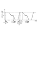
まず、ファン制御部712は、ジョブが投入されると上排出ファン60に比較的風量の大きい第1風量V1での送風を開始させる(S121)。つまり、ファン制御部712は、第1風量V1となるような回転数(第1回転数)で上排出ファン60が回転するように上排出ファン60を制御する。本実施形態において、上排出ファン60は、図8(a)に示すように、上排出ローラ対120の下部近傍に設けられており、上パス排出路117及び上排出ローラ対120のニップ部Nの下方に配置された送風口60aから風が排出される。そして、上排出ファン60は、回転することで風を発生させる羽根車を回転駆動させ、シートSが排出される方向に向けて送風し、シートSの下面に風を当てる。つまり、上排出ファン60は、上排出ローラ対120が搬送している最中のシートの下面及び上積載トレイ136に積載された最上位のシートの上面に沿って風が流れるように送風する。このように、シートSが排出される方向に向けて送風を行う上排出ファン60は、本実施形態における送風部を構成する。
First, when the job is input, the fan control unit 712 causes the
次に、ファン制御部712は、上述したステップS103の処理で積載トレイ制御部711の上パス検知センサS17にシートSの先端が検知されてから、L1mm搬送されたか否かを判定する(S122)。次に、ファン制御部712は、上排出ファン60に送風させる風量を第1風量V1から比較的風量の小さい第2風量V2に切り替える(S123)。つまり、ファン制御部712は、第2風量V2となるような、第1風量V1となる回転数よりも少ない回転数(第2回転数)で上排出ファン60が回転するように上排出ファン60を制御する。次に、ファン制御部712は、シートSの後端が上排出ローラ対120のニップ部Nを抜けてから300ms経過したか否かを判定し(S124)、300ms経過していない場合には(S124でNo)、300ms経過するまでS124の処理を繰り返す。そして、300ms経過したと判定した場合には(S124でYes)、ファン制御部712は、上排出ファン60に送風させる風量を第2風量V2から第1風量V1に切り替える(S125)。
Next, the fan control unit 712 determines whether or not the sheet S has been conveyed L1 mm after the leading edge of the sheet S is detected by the upper path detection sensor S17 of the stacking
ステップS121〜S125においてファン制御部712が実行する制御処理の詳細について説明する。本実施形態において、上積載トレイ136は、排出方向上流側に設けられシートSの排出方向に対して比較的急勾配からなる第1面136aを有している。また、上積載トレイ136は、第1面に対して緩勾配からなる排出方向下流側に設けられた第2面136bと、第1面136aと第2面136bとの接続箇所である接続部136cと、を有している。第1面136aは、水平面に対して角度θを有するように傾斜している。このため、上積載トレイ136上においては、第1面136aに積載されたシートSが自重により排出方向上流側に移動可能となっている。
Details of the control processing executed by the fan control unit 712 in steps S121 to S125 will be described. In the present embodiment, the upper stacking
そして、上積載トレイ136における接続部136cの位置は、図8(a)に示すように、上パス検知センサS17から略L1mmの位置となっている。つまり、距離L1は、上排出ファン60からの送風がない場合、上排出ローラ対120で排出されるシートSの先端が、上積載トレイ136に当接する長さに相当する。図8(b)に示すように、仮に上排出ファン60による送風を実行しない場合、接続部136cの近傍までシートSの先端が到達すると、上積載トレイ136上の積載シートに排出シートの先端が当接し、排出シートによる積載シートの押し出しが発生し得る。そのため、本実施形態においては、上パス検知センサS17から接続部136cの位置までシートSを排出している間は、上排出ファン60に第1風量V1で送風させることで、シートSの先端が積載シートに当接し押し出してしまうことを防止している。つまり、第1風量V1は、排出シートの先端により積載シートが押し出されることを防止可能な風量である。
The position of the connecting
また、ステップS122の処理において、ファン制御部712は、上パス検知センサS17をシートSの先端が通過してから排出時間Taが経過したか否かを判定することで、シートSがL1mm搬送されたか否かを判定している。ここで、排出時間Taは、シートSの排出速度から設定される時間である。このため、上パス検知センサS17がシートSの先端を検知してからシートSがL1mm排出されたと判定するまでにかかる排出時間Taの値は、排出速度が速くなった場合には小さい値に設定され、排出速度が遅くなった場合には大きい値に設定される。 In the process of step S122, the fan control unit 712 determines whether or not the discharge time Ta has passed after the leading edge of the sheet S passes through the upper path detection sensor S17, so that the sheet S is conveyed by L1 mm. It is determined whether or not. Here, the discharge time Ta is a time set from the discharge speed of the sheet S. For this reason, the value of the discharge time Ta required from when the upper path detection sensor S17 detects the leading edge of the sheet S until it is determined that the sheet S is discharged L1 mm is set to a small value when the discharge speed is increased. If the discharge speed becomes slow, the value is set to a large value.
ステップS121〜S125の処理における時間の経過と上排出ファン60が送風する風量の変化との関係を図9に示す。本実施形態の上排出ファン60は、風量をV1からV2に変化する際に第1応答時間t1が必要であり、風量をV2からV1に変化する際に第2応答時間t2が必要である。つまり、上排出ファン60は、一般的なファンと同様、応答性が低い構成となっている。
FIG. 9 shows the relationship between the passage of time in the processing of steps S121 to S125 and the change in the air volume blown by the
図9に示すように、ファン制御部712は、シートSの先端がL1mm搬送された時点でステップS123の処理を実行する。ここで、ファン制御部712は、第1風量V1から第2風量V2に切り替えるのに必要な第1応答時間t1が経過する以前に、シートSの後端が上排出ローラ対120のニップ部Nを通過することを避ける必要がある。
As shown in FIG. 9, the fan control unit 712 executes the process of step S123 when the leading edge of the sheet S is conveyed by L1 mm. Here, before the first response time t1 necessary for switching from the first air volume V1 to the second air volume V2 elapses, the fan controller 712 has the trailing edge of the sheet S at the nip portion N of the upper
そのため、ファン制御部712は、シートSの先端がL1mm搬送される排出時間Taを経過した時点から上排出ファン60が送風する風量を第1風量V1から第2風量V2に切り替え開始する。これにより、ファン制御部712は、シートSの後端がニップ部Nを通過する以前に、上排出ファン60が送風する風量を第1風量V1から第2風量V2に切り替え完了可能に構成されている。このように、ファン制御部712は、上排出ファン60が第1風量V1から第2風量V2に切り替えるのに必要な第1応答時間t1と、シートSの排出速度と、を用いて、第1風量V1と第2風量V2とを切り替える制御を開始するタイミングを決定している。
Therefore, the fan control unit 712 starts switching the air volume blown by the
ここで、仮にシートSがL1mm搬送された後に第1風量V1から風量0に、すなわち送風を停止するように制御した場合、上排出ファン60が送風する風量は、図10に示すグラフのように変化する。図10に示すように、風量の低下により、第2風量V2となる時刻Tbから風量が0となる時刻Tcまでの間、第2風量V2以下の風量で上排出ファン60による送風が実行される。また、時刻TcからシートSの後端が上排出ローラ対120のニップ部Nを通過する時刻Tdまでの間は、上排出ファン60による送風が停止される。このため、時刻Tbから時刻Tdまでにおいては、図11(a)に示すように、上積載トレイ136上において排出シートの下面が積載シートの上面と摩擦接触する。そして、排出シートの下面と積載シートの上面との間の摩擦μによって、積載シートが排出方向下流側に押し出されてしまうことになる。
Here, if the sheet S is conveyed L1 mm and then controlled from the first air volume V1 to the air volume 0, that is, the air flow is stopped, the air volume blown by the
本実施形態において、ファン制御部712は、上述した通りシートSがL1mm搬送された後に、上排出ファン60の風量が第1風量V1から第2風量V2に切り替わるように制御する。また、第2風量V2に切り替えた後、ファン制御部712は、上排出ローラ対120のニップ部NをシートSの後端が通過して300ms経過するまで、上排出ファン60に第2風量V2での送風を実行させる。これにより、図11(b)に示すように、ファン制御部712は、排出シートの下面と積載シートの上面との間に空気を介在させて摩擦力が生じないようにするいわゆるエアルブリケーション状態にすることができる。エアルブリケーション状態にすることで、ファン制御部712は、排出シートの下面と積載シートの上面との摩擦接触を防止し、摩擦μによって積載シートが排出方向下流側に押し出されることを防止することができる。なお、積載シートが1枚もない状態で第2風量V2で送風した場合、上積載トレイ136上においては、排出シートが排出された後上積載トレイ136と排出された排出シートの下面との間に空気が介在する。
In the present embodiment, the fan control unit 712 performs control so that the air volume of the
また、上排出ローラ対120のニップ部NをシートSの後端が通過した際に第1風量V1で送風を実行すると、排出シートの着地点が大幅に排出方向の下流側となってしまい、上積載トレイ136から落下する可能性もある。落下しない場合であっても、積載トレイ136において、幅方向揃え部200及びトレイパドル300によって幅方向及び排出方向の整合を行う際に、上排出ファン60から第1風量V1で送風される風の影響を受けて、積載シートの先端の挙動が暴れやすい。このため、第2風量V2に切り替えることなく第1風量V1での送風を継続した場合、上積載トレイ136上においては、積載シートの位置が不安定となりやすく、積載シートの排出方向及び幅方向の位置の安定性(積載性)に欠けてしまう。
Further, when the air is blown with the first air volume V1 when the trailing edge of the sheet S passes through the nip portion N of the upper
しかしながら、ファン制御部712は、図9にも示すように、シートSの後端が上排出ローラ対120のニップ部Nを通過する際には、上排出ファン60から送風される風量を第1風量V1よりも少ない第2風量V2に切り替え完了するように制御している。このように制御することで、フィニッシャ100は、排出シートの着地点が排出方向下流側に大きくずれることを防止している。つまり、第2風量V2は、第1風量V1よりも少なく排出シートの下面により積載シートが押し出されることを防止可能な風量で且つ排出シートの排出方向での位置(着地点)が安定する風量である。
However, as shown in FIG. 9, the fan control unit 712 also determines the amount of air blown from the
第2風量V2の詳細について、図12を用いて説明する。図12は、第2風量V2の強さとシートSの坪量との関係をグラフにしたものである。例えば坪量M1のシートのような坪量の小さいシートに画像を形成する場合、第2風量V2の風量が強すぎると軽いシートに強い風を当てることになる。このため、図12に示すように、積載性が低下し、上積載トレイ136から落下する可能性が高くなる。
Details of the second air volume V2 will be described with reference to FIG. FIG. 12 is a graph showing the relationship between the strength of the second air volume V2 and the basis weight of the sheet S. For example, when an image is formed on a sheet having a small basis weight such as a sheet having a basis weight M1, if the air volume of the second air volume V2 is too strong, a strong wind is applied to a light sheet. For this reason, as shown in FIG. 12, the loadability is lowered, and the possibility of dropping from the
また、例えば坪量M4のシートのような坪量の大きいシートに画像を形成する場合、第2風量V2の風量が弱すぎると、重いシートに弱い風を当てることになる。このため、図12に示すように、排出シートの下面と積載シートの上面との間の摩擦μによる積載シートの押し出しが発生する可能性が高くなる。 For example, when an image is formed on a sheet having a large basis weight such as a sheet having a basis weight M4, if the air volume of the second air volume V2 is too weak, a weak wind is applied to a heavy sheet. For this reason, as shown in FIG. 12, there is a high possibility that the stacked sheets are pushed out due to the friction μ between the lower surface of the discharged sheets and the upper surface of the stacked sheets.
このように、画像が形成されるシートの坪量に応じて第2風量V2を設定する必要がある。そこで、ファン制御部712は、入力部としての操作部601に入力されるシートSのシート情報のうちシートの坪量に基づいて第2風量V2を変更可能に構成されている。特に、坪量の異なる複数のシートに画像を形成する場合には、図12に示すように、坪量M1〜M4に対応した第2風量V2−1〜V2−4のように、坪量毎に第2風量V2の設定値を設定する必要がある。なお、ファン制御部712は、坪量毎に第2風量V2の設定値を有するほかに、普通紙とコート紙といった紙種毎で異なる設定値を有するように構成されているとなおよい。
Thus, it is necessary to set the second air volume V2 according to the basis weight of the sheet on which the image is formed. Therefore, the fan control unit 712 is configured to be able to change the second air volume V2 based on the basis weight of the sheet in the sheet information of the sheet S input to the
そして、ファン制御部712は、次回の排出シートの先端が上排出ローラ対120のニップ部Nに突入する以前に、上排出ファン60が送風する風量を第2風量V2から第1風量V1に切り替えるために、切り替えに必要な第2応答時間t2を見越して制御する。つまり、ファン制御部712は、前のシートがニップ部Nを抜けた後に次のシートがニップ部Nに到達するまでの時間が短く生産性が高い場合には、300ms以前にステップS125の処理を開始する必要がある。本実施形態においては、シートSの後端が上排出ローラ対120のニップ部Nを抜けてから300ms経過後にステップS125の処理を実行することで、次回の排出シートの先端が上排出ローラ対120のニップ部Nに突入する以前に風量の切り替えを完了できる。なお、シートSの後端が上排出ローラ対120のニップ部Nを通過してから300ms経過するまでの間においては、上述したステップS105,S106で実行される積載シートの搬送方向及び幅方向を整合する処理が実行されている。
Then, the fan control unit 712 switches the air volume blown by the
ステップS125の処理を実行した後、ファン制御部712は、ステップS104で上排出ローラ対120を抜けたシートSが投入されたジョブにおける最後のシートか否かを判定する(S126)。この処理において、ファン制御部712は、上述した積載トレイ制御部711によるステップS109の処理と同様の処理を実行する。そして、最後のシートではないと判定した場合には(S126でNo)、ファン制御部712は、ステップS122に処理を戻す。また、最後のシートであると判定した場合には(S126でYes)、ファン制御部712は、処理を終了する。
After executing the process of step S125, the fan control unit 712 determines whether or not the sheet S that has passed through the upper
以上のように、本発明のフィニッシャ100は、上パス検知センサS17によって検知されるシートSの位置に応じて上排出ファン60の風量を第1風量V1と、第2風量V2とに切り替える制御をファン制御部712が実行する。このため、第1風量V1で送風することで、上排出ローラ対120によって排出されるシートSの先端により上積載トレイ136に積載されたシートが、シートSの排出方向の下流側に押し出されることを防止可能となる。また、第2風量V2で送風するように切り替えることで、上排出ローラ対120によって排出されるシートSの下面により上積載トレイ136に積載されたシートが押し出されることを防止可能となる。さらに、第1風量V1よりも弱い第2風量V2で送風することで、上積載トレイ136に積載されるシートSの着地点が大幅に排出方向の下流側になることを防止可能なため、上積載トレイ136に積載されるシートSを安定して積載可能となる。
As described above, the
なお、本実施形態において、ファン制御部712は、シートSの先端がL1mm搬送された場合に上排出ファン60に送風させる風量を第1風量V1から第2風量V2に切り替えるように制御しているが、これに限定されない。フィニッシャ100において、シートSが上排出ローラ対120のニップ部Nを通過している際に第1風量V1で上排出ファン60が送風することは、シートSがニップ部Nで挟持されていることからシートSの積載性に影響を与えない。このため、ファン制御部712は、シートSの先端がL1mm搬送された後も第1風量V1での送風を継続し、シートSの後端がニップ部Nを通過する直前に風量が第2風量V2に切り替わるように制御してもよい。シートSの後端がニップ部Nを通過する直前に風量が第2風量V2に切り替わるように構成した場合、フィニッシャ100は、排出シートの下面と積載シートの上面との間の摩擦μにより積載シートが排出方向下流側に押し出されることをより確実に防止できる。
In the present embodiment, the fan control unit 712 controls the air volume to be blown to the
また、本実施形態において、ファン制御部712は、シートSの後端がニップ部Nを通過してから300ms経過した場合に上排出ファン60に送風させる風量を第2風量V2から第1風量V1への切り替えを開始するように制御しているが、これに限定されない。上述したように、シートSの後端がニップ部Nを通過してから300ms経過するまでの間においては、ステップS105,S106(図5参照)で実行される積載シートの搬送方向及び幅方向を整合する処理が実行されている。積載シートの搬送方向及び幅方向を整合する処理を実行する場合においては、送風の影響を受けることによるシートSの先端の挙動のばらつき等を考慮すると、風量が少ない方が積載シートが排出方向上流側に移動しやすくできる。そのため、ファン制御部712は、シートSの後端がニップ部Nを通過してから300ms経過した以降も第2風量V2での送風を継続し、シートSの先端がニップ部Nに搬送される直前に風量が第1風量V1に切り替わるように制御してもよい。このように構成した場合、フィニッシャ100は、シートSの先端による上積載トレイ136に積載されたシートの排出方向下流側への押し出しを防止しつつ、上積載トレイ136に積載されるシートの積載性をより向上させることができる。
Further, in the present embodiment, the fan control unit 712 changes the air volume to be blown to the
また、ファン制御部712は、図13に示すように、シートSの後端が上排出ローラ対120のニップ部Nを通過した後に、上排出ファン60による送風を停止するように構成されていてもよい。なお、このように構成した場合、前のシートの後端がニップ部Nを抜けてから、次のシートの先端がニップ部Nに突入するまでに、上排出ファン60の風量を風量0から第1風量V1に切り替え完了する必要がある。このため、このように構成するためには、非常に応答性が高いファンを用いるか、又は生産性が低い場合である必要がある。
Further, as shown in FIG. 13, the fan control unit 712 is configured to stop the blowing by the
また、本実施形態において、ファン制御部712は、上排出ファン60の風量を第1風量V1と第2風量V2とに切り替えるように制御するが、これに限定されない。上述した通り、上排出ファン60は、応答性が低い構成となっている。また、A4サイズのような搬送方向の長さが短いシートSである場合、シートSの排出時にシートSが排出方向下流側にずれる距離は、第1風量V1による送風であってもあまり大きくない。このため、ファン制御部712は、操作部601から入力されたシートのサイズがA4サイズのような搬送方向の長さが所定サイズよりも短いシートである場合には、風量を切り替える制御を実行せずに第1風量V1にしたままでシートを排出する。そしてA3サイズのような、搬送方向の長さが所定サイズ以上のシートである場合には、シートを上排出ローラ対120が搬送している最中に、上排出ファン60の風量を第1風量V1から第2風量V2に切り替える制御を実行する。このように、ファン制御部712は、上排出ファン60の風量を切り替える制御の実行可否を、シートSのサイズに応じて変更するように構成してもよい。
In the present embodiment, the fan control unit 712 performs control so that the air volume of the
また、本実施形態においては、代表例として、上積載トレイ136への未綴じ状態のシートの排出動作を用いて説明したが、例えば下積載トレイ137への未綴じ状態のシートの排出動作であってもよい。この場合、フィニッシャ100は、下積載トレイ137にも上排出ファン60と同様の下排出ファンを備える必要がある。また、未綴じ状態のシートに限らず、ステイプルされたシートを排出する際の動作であっても本発明を適用し得る。
Further, in the present embodiment, as a representative example, the description has been given by using the operation of discharging the unbound sheets to the upper stacking
100…フィニッシャ(シート積載装置):60…上排出ファン(送風部材):60a…送風口:117…上パス排出路(搬送路):120…上排出ローラ対(排出部):136…上積載トレイ(積載部):136a…第1面:136b…第2面:136c…接続部:604…画像形成部:712…ファン制御部(風量制御部):1000…複写機(画像形成装置)S…シート:S17…上パス検知センサ(シート検知部):V1…第1風量:V2…第2風量
DESCRIPTION OF
Claims (19)
前記排出部によって排出されたシートが積載される積載部と、
前記排出部によって排出されるシートの下面に向けて送風する送風部と、
排出されるシートの排出方向における長さが第1長さの場合に、第1モードを実行し、
排出されるシートの排出方向における長さが第1長さよりも長い第2長さの場合に、第2モードを実行する制御部と、を備え、
前記制御部は、前記第1モードにおいて、前記排出部の前記ニップ部がシートを挟持して搬送しているときに、シートに送風する風量を変更しないように前記送風部を制御し、前記第2モードにおいて、前記排出部の前記ニップ部がシートを挟持して搬送しているときに、シートに送風する風量を第1風量から減少させ、かつ前記ニップ部をシートの後端が抜けるときに前記第1風量よりも少ない第2風量で当該シートに送風するように前記送風部を制御する、
ことを特徴とするシート積載装置。 A nip portion for nipping and conveying the sheet, and a discharge portion for discharging the sheet;
A stacking unit on which sheets discharged by the discharging unit are stacked;
A blower for blowing air toward the lower surface of the sheet discharged by the discharger;
When the length of the discharged sheet in the discharge direction is the first length, the first mode is executed,
A control unit that executes the second mode when the length of the discharged sheet in the discharge direction is a second length that is longer than the first length; and
In the first mode, the control unit controls the air blowing unit so as not to change the amount of air blown to the sheet when the nip portion of the discharge unit sandwiches and conveys the sheet. in 2 mode, when the nip of the discharge portion is conveyed by nipping the sheet, the amount of air blown to the sheet to decline from the first air volume, and when the trailing edge of the nip sheet escapes The air blowing unit is controlled to blow air to the seat with a second air volume smaller than the first air volume .
A sheet stacking apparatus characterized by that.
ことを特徴とする請求項1に記載のシート積載装置。 In the second mode, the control unit controls the air blowing unit so that when the leading end of the sheet discharged by the discharge unit passes through the nip portion, the air is blown to the sheet with the first air volume.
The sheet stacking apparatus according to claim 1, wherein:
前記積載部は、第1面と、前記第1面の前記排出方向における上流に配置され、前記突き当て部に対して下り傾斜する第2面と、を有し、
前記第2面の水平面に対する傾斜角度は、前記第1面の水平面に対する傾斜角度よりも大きい、
ことを特徴とする請求項1又は2に記載のシート積載装置。 An abutting portion that is disposed upstream of the stacking portion in the discharge direction and that a rear end of a sheet stacked on the stacking portion abuts;
The loading portion includes a first surface and a second surface that is disposed upstream of the first surface in the discharge direction and is inclined downward with respect to the abutting portion,
The inclination angle of the second surface with respect to the horizontal plane is greater than the inclination angle of the first surface with respect to the horizontal plane,
The sheet stacking apparatus according to claim 1, wherein the sheet stacking apparatus is a sheet stacking apparatus.
ことを特徴とする請求項3に記載のシート積載装置。 A rotating member that conveys the sheet so that the rear end of the sheet abuts against the abutting unit by contacting and rotating the uppermost sheet of the sheets stacked on the stacking unit;
The sheet stacking apparatus according to claim 3.
ことを特徴とする請求項4に記載のシート積載装置。 A moving unit that moves the rotating member to a position in contact with the sheets stacked on the stacking unit and a position away from the sheets stacked on the stacking unit;
The sheet stacking apparatus according to claim 4, wherein
ことを特徴とする請求項1乃至5のいずれか1項に記載のシート積載装置。 In the second mode, when the discharge unit continuously discharges the succeeding sheets with respect to the preceding sheet, before the leading edge of the sheet following the discharge unit reaches the blower unit, Controlling the air blowing section so that the change of the air volume to the first air volume is completed,
The sheet stacking apparatus according to claim 1, wherein the sheet stacking apparatus is a sheet stacking apparatus.
前記制御部は、前記第2モードにおいて、前記ファンの回転速度を変更することで、前記風量を変更する、
ことを特徴とする請求項1乃至6のいずれか1項に記載のシート積載装置。 The air blowing unit includes a rotating fan, and the control unit changes the air volume by changing a rotation speed of the fan in the second mode.
The sheet stacking apparatus according to claim 1, wherein the sheet stacking apparatus is a sheet stacking apparatus.
ことを特徴とする請求項1乃至7のいずれか1項に記載のシート積載装置。 The control unit is capable of changing the second air volume based on information on the sheet discharged by the discharge unit.
Sheet stacking apparatus according to any one of claims 1 to 7, characterized in that.
ことを特徴とする請求項1乃至7のいずれか1項に記載のシート積載装置。 The control unit is capable of changing the second air volume based on the basis weight of the sheet discharged by the discharge unit.
Sheet stacking apparatus according to any one of claims 1 to 7, characterized in that.
前記搬送路におけるシートの位置を検知する第1検知部と、を備え、
前記制御部は、前記第2モードにおいて、前記第1検知部の検知結果に基づいて、前記送風部の風量を変更する、
ことを特徴とする請求項1乃至9のいずれか1項に記載のシート積載装置。 A conveyance path through which a sheet toward the discharge unit passes,
A first detection unit that detects the position of the sheet in the conveyance path,
The control unit, in the second mode, changes the air volume of the blowing unit based on the detection result of the first detection unit.
Sheet stacking apparatus according to any one of claims 1 to 9, characterized in that.
ことを特徴とする請求項1乃至10のいずれか1項に記載のシート積載装置。 The blower blows along the discharge direction between the lower surface of the sheet sandwiched by the nip and the uppermost sheet stacked on the stack.
Sheet stacking apparatus according to any one of claims 1 to 1 0, characterized in that.
前記制御部は、前記記憶部が記憶した長さ情報に基づいて、前記第1モード及び前記第2モードを含む複数のモードのうちから1つのモードを実行する、
ことを特徴とする請求項1乃至11のいずれか1項に記載のシート積載装置。 A storage unit for storing length information of the discharge direction of the sheet;
The control unit executes one mode from a plurality of modes including the first mode and the second mode based on the length information stored in the storage unit.
Sheet stacking apparatus according to any one of claims 1 to 1 1, characterized in that.
ことを特徴とする請求項1乃至12のいずれか1項に記載のシート積載装置。 An alignment member that moves in a width direction orthogonal to the discharge direction and performs an alignment operation to align the sheets stacked on the stacking unit;
Sheet stacking apparatus according to any one of claims 1 to 1 2, characterized in that.
ことを特徴とする請求項13に記載のシート積載装置。 The alignment member performs the alignment operation when the air blowing unit is blowing air.
Sheet stacking apparatus according to claim 1 3, characterized in that.
前記積載部に積載されたシートの最上位のシートを検知する第2検知部と、を備え、
前記送風部は、前記ニップ部の下方に配置され風を吹き出す開口を有し、
前記昇降部は、前記積載部に積載された最上位のシートの後端が前記開口よりも下方となるように、前記第2検知部の検知結果に基づいて前記積載部を昇降させる、
ことを特徴とする請求項1乃至14のいずれか1項に記載のシート積載装置。 An elevating unit for elevating and lowering the loading unit;
A second detection unit that detects the uppermost sheet of the sheets stacked on the stacking unit,
The air blowing part has an opening that is arranged below the nip part and blows out air.
The elevating unit elevates and lowers the stacking unit based on the detection result of the second detection unit such that the rear end of the uppermost sheet stacked on the stacking unit is below the opening.
Sheet stacking apparatus according to any one of claims 1 to 1 4, characterized in that.
前記排出部によって排出されたシートが積載される積載部と、
前記ニップ部の下方に配置された開口から送風する送風部と、を備え、
前記送風部によって前記開口から送風された風は、前記ニップ部によってニップされているシートと前記積載部に積載されたシートの最上位のシートとの間を流れ、
排出されるシートの排出方向における長さが第1長さの場合、前記排出部の前記ニップ部がシートを挟持して搬送しているときに、前記開口から送風される風の風量は一定であり、
排出されるシートの前記排出方向における長さが前記第1長さよりも長い第2長さの場合、前記排出部の前記ニップ部がシートを挟持して搬送しているときに、前記開口から送風される風の風量は第1風量から減少し、かつ前記ニップ部をシートの後端が通過するときに、前記第1風量よりも少ない第2風量の風が前記開口から送風される、
ことを特徴とするシート積載装置。 A nip portion for nipping and conveying the sheet, and a discharge portion for discharging the sheet;
A stacking unit on which sheets discharged by the discharging unit are stacked;
An air blower that blows air from an opening disposed below the nip, and
The air blown from the opening by the blowing unit flows between the sheet nipped by the nip unit and the uppermost sheet stacked on the stacking unit,
When the length of the discharged sheet in the discharge direction is the first length, the amount of air blown from the opening is constant when the nip portion of the discharge unit sandwiches and conveys the sheet. Yes,
When the length of the discharged sheet in the discharge direction is a second length that is longer than the first length, air is blown from the opening when the nip portion of the discharge unit holds and conveys the sheet. the volume of the air is slightly reduced from the first air volume, and the nip portion when the trailing edge of the sheet passes, the wind of the second air volume smaller than the first flow rate is blown from said opening,
A sheet stacking apparatus characterized by that.
前記ファンを制御する制御部を備え、
前記制御部は、前記第1長さのシートを排出する場合、前記ニップ部が前記シートを挟持して搬送しているときに前記ファンの回転速度を一定に維持し、前記第2長さのシートを排出する場合、前記ニップ部が前記シートを挟持して搬送しているときに前記ファンの回転速度が遅くなるように、前記ファンを制御する、
ことを特徴とする請求項16に記載のシート積載装置。 The blower unit has a fan that generates wind blown from the opening by rotating,
A control unit for controlling the fan;
The controller, when discharging the sheet of the first length, maintains the rotation speed of the fan constant when the nip portion sandwiches and conveys the sheet, and the second length of the sheet When discharging the sheet, the fan is controlled so that the rotational speed of the fan becomes slow when the nip portion sandwiches and conveys the sheet.
The sheet stacking apparatus according to claim 16 .
前記積載部に積載されたシートの最上位のシートを検知する検知部と、を備え、
前記昇降部は、前記積載部に積載された最上位のシートの後端が前記開口よりも下方となるように、前記検知部の検知結果に基づいて前記積載部を昇降させる、
ことを特徴とする請求項16又は17に記載のシート積載装置。 An elevating unit for elevating and lowering the loading unit;
A detection unit that detects the uppermost sheet of the sheets stacked on the stacking unit,
The elevating unit elevates and lowers the stacking unit based on the detection result of the detection unit so that the rear end of the uppermost sheet stacked on the stacking unit is below the opening.
The sheet stacking apparatus according to claim 16 or 17 , characterized in that:
前記画像形成部によって画像を形成されたシートを積載する請求項1乃至18のいずれか1項に記載のシート積載装置と、を備える、
ことを特徴とする画像形成装置。 An image forming unit for forming an image on a sheet;
The sheet stacking apparatus according to any one of claims 1 to 18 , which stacks a sheet on which an image is formed by the image forming unit.
An image forming apparatus.
Priority Applications (3)
| Application Number | Priority Date | Filing Date | Title |
|---|---|---|---|
| JP2015154275A JP6622508B2 (en) | 2015-08-04 | 2015-08-04 | Sheet stacking apparatus and image forming apparatus |
| US15/223,130 US9914611B2 (en) | 2015-08-04 | 2016-07-29 | Sheet stacking apparatus and image forming apparatus |
| US15/878,637 US10183829B2 (en) | 2015-08-04 | 2018-01-24 | Sheet stacking apparatus and image forming apparatus |
Applications Claiming Priority (1)
| Application Number | Priority Date | Filing Date | Title |
|---|---|---|---|
| JP2015154275A JP6622508B2 (en) | 2015-08-04 | 2015-08-04 | Sheet stacking apparatus and image forming apparatus |
Publications (3)
| Publication Number | Publication Date |
|---|---|
| JP2017030950A JP2017030950A (en) | 2017-02-09 |
| JP2017030950A5 JP2017030950A5 (en) | 2018-09-13 |
| JP6622508B2 true JP6622508B2 (en) | 2019-12-18 |
Family
ID=57987539
Family Applications (1)
| Application Number | Title | Priority Date | Filing Date |
|---|---|---|---|
| JP2015154275A Active JP6622508B2 (en) | 2015-08-04 | 2015-08-04 | Sheet stacking apparatus and image forming apparatus |
Country Status (2)
| Country | Link |
|---|---|
| US (2) | US9914611B2 (en) |
| JP (1) | JP6622508B2 (en) |
Families Citing this family (8)
| Publication number | Priority date | Publication date | Assignee | Title |
|---|---|---|---|---|
| JP6622508B2 (en) * | 2015-08-04 | 2019-12-18 | キヤノン株式会社 | Sheet stacking apparatus and image forming apparatus |
| JP6771904B2 (en) | 2016-03-01 | 2020-10-21 | キヤノン株式会社 | Sheet loading device and image forming device |
| JP7052433B2 (en) * | 2018-03-07 | 2022-04-12 | 株式会社リコー | Sheet loading device, image forming device and image forming system |
| JP7052565B2 (en) * | 2018-05-29 | 2022-04-12 | 京セラドキュメントソリューションズ株式会社 | Sheet post-processing device and image forming system equipped with it |
| US11460805B2 (en) * | 2019-01-16 | 2022-10-04 | Kyocera Document Solutions Inc. | Image forming apparatus with a cooling fan which suppresses sticking of sheets |
| JP2021181354A (en) | 2020-05-19 | 2021-11-25 | キヤノン株式会社 | Measuring device, image reading device and image forming system |
| JP2021190876A (en) | 2020-05-29 | 2021-12-13 | キヤノン株式会社 | Image reading device and image forming system |
| JP2021190877A (en) | 2020-05-29 | 2021-12-13 | キヤノン株式会社 | Image reading device and image forming system |
Family Cites Families (16)
| Publication number | Priority date | Publication date | Assignee | Title |
|---|---|---|---|---|
| JP4677218B2 (en) * | 2004-10-29 | 2011-04-27 | キヤノン株式会社 | Image forming apparatus |
| JP2006293067A (en) * | 2005-04-12 | 2006-10-26 | Canon Inc | Image forming apparatus |
| JP5344602B2 (en) * | 2009-07-10 | 2013-11-20 | キヤノン株式会社 | Image forming apparatus |
| JP2011057313A (en) | 2009-09-07 | 2011-03-24 | Ricoh Co Ltd | Sheet ejecting device and image forming device |
| JP5269164B2 (en) * | 2010-10-14 | 2013-08-21 | キヤノン株式会社 | Sheet discharging apparatus, sheet processing apparatus, and image forming apparatus |
| JP5804828B2 (en) * | 2011-07-29 | 2015-11-04 | キヤノン株式会社 | Sheet stacking apparatus and image forming system |
| JP6004801B2 (en) | 2011-07-29 | 2016-10-12 | キヤノン株式会社 | Sheet stacking apparatus and image forming apparatus |
| JP5911329B2 (en) | 2012-02-17 | 2016-04-27 | キヤノン株式会社 | Sheet processing apparatus and image forming system |
| JP5783164B2 (en) * | 2012-03-02 | 2015-09-24 | 株式会社リコー | Paper discharge device and image forming system |
| JP5645992B2 (en) | 2012-04-27 | 2014-12-24 | キヤノン株式会社 | Sheet stacking apparatus, sheet processing apparatus, and image forming apparatus |
| JP5474228B2 (en) | 2012-04-27 | 2014-04-16 | キヤノン株式会社 | Sheet stacking apparatus and image forming apparatus |
| JP5511883B2 (en) | 2012-04-27 | 2014-06-04 | キヤノン株式会社 | Sheet stacking apparatus and image forming apparatus |
| JP5786829B2 (en) | 2012-08-31 | 2015-09-30 | 株式会社リコー | Paper discharge device, paper processing device, and image forming system |
| JP2014047046A (en) * | 2012-08-31 | 2014-03-17 | Ricoh Co Ltd | Sheet discharge device and image forming system |
| JP6622508B2 (en) * | 2015-08-04 | 2019-12-18 | キヤノン株式会社 | Sheet stacking apparatus and image forming apparatus |
| US9821978B2 (en) * | 2016-03-23 | 2017-11-21 | Xerox Corporation | Sheet stacking system for flimsy sheets |
-
2015
- 2015-08-04 JP JP2015154275A patent/JP6622508B2/en active Active
-
2016
- 2016-07-29 US US15/223,130 patent/US9914611B2/en active Active
-
2018
- 2018-01-24 US US15/878,637 patent/US10183829B2/en active Active
Also Published As
| Publication number | Publication date |
|---|---|
| US10183829B2 (en) | 2019-01-22 |
| JP2017030950A (en) | 2017-02-09 |
| US9914611B2 (en) | 2018-03-13 |
| US20170036881A1 (en) | 2017-02-09 |
| US20180155146A1 (en) | 2018-06-07 |
Similar Documents
| Publication | Publication Date | Title |
|---|---|---|
| JP6622508B2 (en) | Sheet stacking apparatus and image forming apparatus | |
| JP5344571B2 (en) | Sheet stacking apparatus and sheet processing apparatus including the same | |
| JP5031522B2 (en) | Sheet discharging apparatus, sheet processing apparatus, and image forming apparatus | |
| JP4819636B2 (en) | Sheet processing apparatus and image forming apparatus | |
| JP5786829B2 (en) | Paper discharge device, paper processing device, and image forming system | |
| JP2017030946A (en) | Sheet processing method, sheet processing device, and image formation device | |
| JP6579822B2 (en) | Image forming apparatus and sheet processing apparatus | |
| JP6800646B2 (en) | Transport device | |
| JP2020090375A (en) | Sheet loading device and image formation system | |
| JP2010006537A (en) | Sheet processing device | |
| JP4785513B2 (en) | Image forming apparatus | |
| JP5394871B2 (en) | Sheet processing apparatus and image forming apparatus | |
| JP2010159102A (en) | Sheet processing device and image forming device | |
| JP4859193B2 (en) | Sheet post-processing control method and image forming apparatus | |
| JP2007084269A (en) | Sheet treatment device and image forming device | |
| JP2020090374A (en) | Sheet loading device and image formation system | |
| JP7240159B2 (en) | Sheet stacking device and image forming system | |
| JP5744272B2 (en) | Sheet stacking apparatus and image forming apparatus | |
| JP7471809B2 (en) | Sheet stacking device and image forming system | |
| JP5506862B2 (en) | Sheet discharging apparatus, sheet processing apparatus, and image forming apparatus | |
| JP2002321861A (en) | Sheet processing unit and image forming device | |
| JP5571723B2 (en) | Paper processing apparatus and paper conveying method | |
| JP2020132333A (en) | Sheet carrier | |
| JP2021100879A (en) | Sheet stacking apparatus | |
| JP2020104959A (en) | Sheet transfer device, sheet post-processing device, image forming apparatus, and image forming system |
Legal Events
| Date | Code | Title | Description |
|---|---|---|---|
| A521 | Request for written amendment filed |
Free format text: JAPANESE INTERMEDIATE CODE: A523 Effective date: 20180802 |
|
| A621 | Written request for application examination |
Free format text: JAPANESE INTERMEDIATE CODE: A621 Effective date: 20180802 |
|
| A977 | Report on retrieval |
Free format text: JAPANESE INTERMEDIATE CODE: A971007 Effective date: 20190524 |
|
| A131 | Notification of reasons for refusal |
Free format text: JAPANESE INTERMEDIATE CODE: A131 Effective date: 20190611 |
|
| A521 | Request for written amendment filed |
Free format text: JAPANESE INTERMEDIATE CODE: A523 Effective date: 20190809 |
|
| TRDD | Decision of grant or rejection written | ||
| A01 | Written decision to grant a patent or to grant a registration (utility model) |
Free format text: JAPANESE INTERMEDIATE CODE: A01 Effective date: 20191023 |
|
| A61 | First payment of annual fees (during grant procedure) |
Free format text: JAPANESE INTERMEDIATE CODE: A61 Effective date: 20191122 |
|
| R151 | Written notification of patent or utility model registration |
Ref document number: 6622508 Country of ref document: JP Free format text: JAPANESE INTERMEDIATE CODE: R151 |