JP6621851B2 - Method and computer system for processing cardiac sensor output - Google Patents
Method and computer system for processing cardiac sensor output Download PDFInfo
- Publication number
- JP6621851B2 JP6621851B2 JP2017563245A JP2017563245A JP6621851B2 JP 6621851 B2 JP6621851 B2 JP 6621851B2 JP 2017563245 A JP2017563245 A JP 2017563245A JP 2017563245 A JP2017563245 A JP 2017563245A JP 6621851 B2 JP6621851 B2 JP 6621851B2
- Authority
- JP
- Japan
- Prior art keywords
- blood pressure
- sensed
- pressure
- aortic
- value
- Prior art date
- Legal status (The legal status is an assumption and is not a legal conclusion. Google has not performed a legal analysis and makes no representation as to the accuracy of the status listed.)
- Active
Links
- 230000000747 cardiac effect Effects 0.000 title claims description 198
- 238000000034 method Methods 0.000 title claims description 80
- 238000012545 processing Methods 0.000 title claims description 54
- 230000036772 blood pressure Effects 0.000 claims description 148
- 230000017531 blood circulation Effects 0.000 claims description 70
- 210000005240 left ventricle Anatomy 0.000 claims description 28
- 210000000709 aorta Anatomy 0.000 claims description 27
- 230000003205 diastolic effect Effects 0.000 claims description 26
- 238000003860 storage Methods 0.000 claims description 24
- 238000004590 computer program Methods 0.000 claims description 20
- 239000003990 capacitor Substances 0.000 claims description 17
- 238000012544 monitoring process Methods 0.000 claims description 11
- 230000036581 peripheral resistance Effects 0.000 claims description 7
- 238000001514 detection method Methods 0.000 claims description 4
- 210000001367 artery Anatomy 0.000 claims description 3
- 239000004020 conductor Substances 0.000 claims 4
- 238000010586 diagram Methods 0.000 description 32
- 230000015654 memory Effects 0.000 description 17
- 210000001765 aortic valve Anatomy 0.000 description 14
- 230000006870 function Effects 0.000 description 13
- 230000008569 process Effects 0.000 description 9
- 230000004872 arterial blood pressure Effects 0.000 description 8
- 230000002861 ventricular Effects 0.000 description 8
- 239000008280 blood Substances 0.000 description 5
- 210000004369 blood Anatomy 0.000 description 5
- 230000035487 diastolic blood pressure Effects 0.000 description 5
- 230000035488 systolic blood pressure Effects 0.000 description 5
- 230000008321 arterial blood flow Effects 0.000 description 4
- 210000005249 arterial vasculature Anatomy 0.000 description 3
- 238000004422 calculation algorithm Methods 0.000 description 3
- 230000000875 corresponding effect Effects 0.000 description 3
- 230000000694 effects Effects 0.000 description 3
- 238000012806 monitoring device Methods 0.000 description 3
- 230000003287 optical effect Effects 0.000 description 3
- 239000004065 semiconductor Substances 0.000 description 3
- 239000007787 solid Substances 0.000 description 3
- 230000009471 action Effects 0.000 description 2
- 238000004364 calculation method Methods 0.000 description 2
- 230000008859 change Effects 0.000 description 2
- 230000007423 decrease Effects 0.000 description 2
- 230000001419 dependent effect Effects 0.000 description 2
- 238000009795 derivation Methods 0.000 description 2
- 238000012804 iterative process Methods 0.000 description 2
- 239000000463 material Substances 0.000 description 2
- 238000005259 measurement Methods 0.000 description 2
- 238000012986 modification Methods 0.000 description 2
- 230000004048 modification Effects 0.000 description 2
- 239000013307 optical fiber Substances 0.000 description 2
- 238000005457 optimization Methods 0.000 description 2
- 230000002093 peripheral effect Effects 0.000 description 2
- 230000000644 propagated effect Effects 0.000 description 2
- 206010002091 Anaesthesia Diseases 0.000 description 1
- 208000028399 Critical Illness Diseases 0.000 description 1
- 101150116102 P4HB gene Proteins 0.000 description 1
- 230000037005 anaesthesia Effects 0.000 description 1
- 230000036592 analgesia Effects 0.000 description 1
- 238000013459 approach Methods 0.000 description 1
- 230000006399 behavior Effects 0.000 description 1
- 238000009530 blood pressure measurement Methods 0.000 description 1
- 210000002302 brachial artery Anatomy 0.000 description 1
- 230000001276 controlling effect Effects 0.000 description 1
- 230000002596 correlated effect Effects 0.000 description 1
- 238000013500 data storage Methods 0.000 description 1
- 230000003111 delayed effect Effects 0.000 description 1
- 210000003709 heart valve Anatomy 0.000 description 1
- 210000001308 heart ventricle Anatomy 0.000 description 1
- 230000000004 hemodynamic effect Effects 0.000 description 1
- 230000006872 improvement Effects 0.000 description 1
- 238000001361 intraarterial administration Methods 0.000 description 1
- 238000004519 manufacturing process Methods 0.000 description 1
- 230000037361 pathway Effects 0.000 description 1
- 230000003836 peripheral circulation Effects 0.000 description 1
- 230000002085 persistent effect Effects 0.000 description 1
- 230000002028 premature Effects 0.000 description 1
- 238000002360 preparation method Methods 0.000 description 1
- 230000004044 response Effects 0.000 description 1
- 230000002441 reversible effect Effects 0.000 description 1
- 238000004088 simulation Methods 0.000 description 1
- 230000001629 suppression Effects 0.000 description 1
- 230000009466 transformation Effects 0.000 description 1
- 230000007704 transition Effects 0.000 description 1
Images


Classifications
-
- A—HUMAN NECESSITIES
- A61—MEDICAL OR VETERINARY SCIENCE; HYGIENE
- A61B—DIAGNOSIS; SURGERY; IDENTIFICATION
- A61B5/00—Measuring for diagnostic purposes; Identification of persons
- A61B5/02—Detecting, measuring or recording pulse, heart rate, blood pressure or blood flow; Combined pulse/heart-rate/blood pressure determination; Evaluating a cardiovascular condition not otherwise provided for, e.g. using combinations of techniques provided for in this group with electrocardiography or electroauscultation; Heart catheters for measuring blood pressure
- A61B5/021—Measuring pressure in heart or blood vessels
- A61B5/0215—Measuring pressure in heart or blood vessels by means inserted into the body
-
- A—HUMAN NECESSITIES
- A61—MEDICAL OR VETERINARY SCIENCE; HYGIENE
- A61B—DIAGNOSIS; SURGERY; IDENTIFICATION
- A61B5/00—Measuring for diagnostic purposes; Identification of persons
- A61B5/02—Detecting, measuring or recording pulse, heart rate, blood pressure or blood flow; Combined pulse/heart-rate/blood pressure determination; Evaluating a cardiovascular condition not otherwise provided for, e.g. using combinations of techniques provided for in this group with electrocardiography or electroauscultation; Heart catheters for measuring blood pressure
- A61B5/021—Measuring pressure in heart or blood vessels
- A61B5/02141—Details of apparatus construction, e.g. pump units or housings therefor, cuff pressurising systems, arrangements of fluid conduits or circuits
-
- A—HUMAN NECESSITIES
- A61—MEDICAL OR VETERINARY SCIENCE; HYGIENE
- A61B—DIAGNOSIS; SURGERY; IDENTIFICATION
- A61B5/00—Measuring for diagnostic purposes; Identification of persons
- A61B5/68—Arrangements of detecting, measuring or recording means, e.g. sensors, in relation to patient
- A61B5/6846—Arrangements of detecting, measuring or recording means, e.g. sensors, in relation to patient specially adapted to be brought in contact with an internal body part, i.e. invasive
- A61B5/6847—Arrangements of detecting, measuring or recording means, e.g. sensors, in relation to patient specially adapted to be brought in contact with an internal body part, i.e. invasive mounted on an invasive device
- A61B5/686—Permanently implanted devices, e.g. pacemakers, other stimulators, biochips
-
- A—HUMAN NECESSITIES
- A61—MEDICAL OR VETERINARY SCIENCE; HYGIENE
- A61M—DEVICES FOR INTRODUCING MEDIA INTO, OR ONTO, THE BODY; DEVICES FOR TRANSDUCING BODY MEDIA OR FOR TAKING MEDIA FROM THE BODY; DEVICES FOR PRODUCING OR ENDING SLEEP OR STUPOR
- A61M60/00—Blood pumps; Devices for mechanical circulatory actuation; Balloon pumps for circulatory assistance
- A61M60/10—Location thereof with respect to the patient's body
- A61M60/122—Implantable pumps or pumping devices, i.e. the blood being pumped inside the patient's body
- A61M60/126—Implantable pumps or pumping devices, i.e. the blood being pumped inside the patient's body implantable via, into, inside, in line, branching on, or around a blood vessel
- A61M60/135—Implantable pumps or pumping devices, i.e. the blood being pumped inside the patient's body implantable via, into, inside, in line, branching on, or around a blood vessel inside a blood vessel, e.g. using grafting
- A61M60/139—Implantable pumps or pumping devices, i.e. the blood being pumped inside the patient's body implantable via, into, inside, in line, branching on, or around a blood vessel inside a blood vessel, e.g. using grafting inside the aorta, e.g. intra-aortic balloon pumps
-
- A—HUMAN NECESSITIES
- A61—MEDICAL OR VETERINARY SCIENCE; HYGIENE
- A61M—DEVICES FOR INTRODUCING MEDIA INTO, OR ONTO, THE BODY; DEVICES FOR TRANSDUCING BODY MEDIA OR FOR TAKING MEDIA FROM THE BODY; DEVICES FOR PRODUCING OR ENDING SLEEP OR STUPOR
- A61M60/00—Blood pumps; Devices for mechanical circulatory actuation; Balloon pumps for circulatory assistance
- A61M60/20—Type thereof
- A61M60/295—Balloon pumps for circulatory assistance
-
- A—HUMAN NECESSITIES
- A61—MEDICAL OR VETERINARY SCIENCE; HYGIENE
- A61M—DEVICES FOR INTRODUCING MEDIA INTO, OR ONTO, THE BODY; DEVICES FOR TRANSDUCING BODY MEDIA OR FOR TAKING MEDIA FROM THE BODY; DEVICES FOR PRODUCING OR ENDING SLEEP OR STUPOR
- A61M60/00—Blood pumps; Devices for mechanical circulatory actuation; Balloon pumps for circulatory assistance
- A61M60/50—Details relating to control
- A61M60/508—Electronic control means, e.g. for feedback regulation
- A61M60/515—Regulation using real-time patient data
- A61M60/523—Regulation using real-time patient data using blood flow data, e.g. from blood flow transducers
-
- A—HUMAN NECESSITIES
- A61—MEDICAL OR VETERINARY SCIENCE; HYGIENE
- A61M—DEVICES FOR INTRODUCING MEDIA INTO, OR ONTO, THE BODY; DEVICES FOR TRANSDUCING BODY MEDIA OR FOR TAKING MEDIA FROM THE BODY; DEVICES FOR PRODUCING OR ENDING SLEEP OR STUPOR
- A61M60/00—Blood pumps; Devices for mechanical circulatory actuation; Balloon pumps for circulatory assistance
- A61M60/50—Details relating to control
- A61M60/508—Electronic control means, e.g. for feedback regulation
- A61M60/515—Regulation using real-time patient data
- A61M60/531—Regulation using real-time patient data using blood pressure data, e.g. from blood pressure sensors
-
- A—HUMAN NECESSITIES
- A61—MEDICAL OR VETERINARY SCIENCE; HYGIENE
- A61M—DEVICES FOR INTRODUCING MEDIA INTO, OR ONTO, THE BODY; DEVICES FOR TRANSDUCING BODY MEDIA OR FOR TAKING MEDIA FROM THE BODY; DEVICES FOR PRODUCING OR ENDING SLEEP OR STUPOR
- A61M60/00—Blood pumps; Devices for mechanical circulatory actuation; Balloon pumps for circulatory assistance
- A61M60/50—Details relating to control
- A61M60/508—Electronic control means, e.g. for feedback regulation
- A61M60/538—Regulation using real-time blood pump operational parameter data, e.g. motor current
- A61M60/554—Regulation using real-time blood pump operational parameter data, e.g. motor current of blood pressure
-
- G—PHYSICS
- G16—INFORMATION AND COMMUNICATION TECHNOLOGY [ICT] SPECIALLY ADAPTED FOR SPECIFIC APPLICATION FIELDS
- G16H—HEALTHCARE INFORMATICS, i.e. INFORMATION AND COMMUNICATION TECHNOLOGY [ICT] SPECIALLY ADAPTED FOR THE HANDLING OR PROCESSING OF MEDICAL OR HEALTHCARE DATA
- G16H40/00—ICT specially adapted for the management or administration of healthcare resources or facilities; ICT specially adapted for the management or operation of medical equipment or devices
- G16H40/60—ICT specially adapted for the management or administration of healthcare resources or facilities; ICT specially adapted for the management or operation of medical equipment or devices for the operation of medical equipment or devices
- G16H40/63—ICT specially adapted for the management or administration of healthcare resources or facilities; ICT specially adapted for the management or operation of medical equipment or devices for the operation of medical equipment or devices for local operation
-
- G—PHYSICS
- G16—INFORMATION AND COMMUNICATION TECHNOLOGY [ICT] SPECIALLY ADAPTED FOR SPECIFIC APPLICATION FIELDS
- G16H—HEALTHCARE INFORMATICS, i.e. INFORMATION AND COMMUNICATION TECHNOLOGY [ICT] SPECIALLY ADAPTED FOR THE HANDLING OR PROCESSING OF MEDICAL OR HEALTHCARE DATA
- G16H50/00—ICT specially adapted for medical diagnosis, medical simulation or medical data mining; ICT specially adapted for detecting, monitoring or modelling epidemics or pandemics
- G16H50/50—ICT specially adapted for medical diagnosis, medical simulation or medical data mining; ICT specially adapted for detecting, monitoring or modelling epidemics or pandemics for simulation or modelling of medical disorders
-
- A—HUMAN NECESSITIES
- A61—MEDICAL OR VETERINARY SCIENCE; HYGIENE
- A61M—DEVICES FOR INTRODUCING MEDIA INTO, OR ONTO, THE BODY; DEVICES FOR TRANSDUCING BODY MEDIA OR FOR TAKING MEDIA FROM THE BODY; DEVICES FOR PRODUCING OR ENDING SLEEP OR STUPOR
- A61M60/00—Blood pumps; Devices for mechanical circulatory actuation; Balloon pumps for circulatory assistance
- A61M60/10—Location thereof with respect to the patient's body
- A61M60/122—Implantable pumps or pumping devices, i.e. the blood being pumped inside the patient's body
- A61M60/126—Implantable pumps or pumping devices, i.e. the blood being pumped inside the patient's body implantable via, into, inside, in line, branching on, or around a blood vessel
- A61M60/148—Implantable pumps or pumping devices, i.e. the blood being pumped inside the patient's body implantable via, into, inside, in line, branching on, or around a blood vessel in line with a blood vessel using resection or like techniques, e.g. permanent endovascular heart assist devices
Description
本発明は、心臓センサ出力を処理する方法及びシステムに関する。より特には、本発明は、心臓センサ出力を処理する方法及びコンピュータ・システムに関し、該心臓センサ出力は、1心周期に亘って、心臓に関連した腔、例えば大動脈又は心臓の左心室、における圧力に関連する。 The present invention relates to a method and system for processing cardiac sensor output. More particularly, the present invention relates to a method and computer system for processing cardiac sensor output, wherein the cardiac sensor output is a pressure in a chamber associated with the heart, such as the aorta or the left ventricle of the heart, over a cardiac cycle. is connected with.
患者の大動脈における血圧及び血流量は、患者の心臓の左心室の負荷を定義する。最大収縮期圧、最小拡張期圧及び平均動脈圧を測定することが実際には知られている。しかしながら、血行力学的状態(負荷)は急速に変化しうる。間隔ベースで血圧及び血流量を測定するシステム(例えば、血圧の為の上腕リバロッチ(Riva-Rocci)方法及び心拍出量の為の熱希釈)は、重篤な患者を監視する為には適していない。 The blood pressure and blood flow in the patient's aorta define the load on the left ventricle of the patient's heart. It is actually known to measure maximum systolic pressure, minimum diastolic pressure and mean arterial pressure. However, the hemodynamic state (load) can change rapidly. Systems that measure blood pressure and blood flow on an interval basis (eg, the Riva-Rocci method for blood pressure and thermodilution for cardiac output) are suitable for monitoring serious patients Not.
従って、動脈の血圧及び血流量の連続的な監視の為の方法及び装置が開発されている。動脈圧を連続的に監視する為に、圧力変換器に接続された圧力線が典型的には動脈内に導入され、そして幾つかの信号処理後に、連続的な圧信号と、収縮期圧、拡張期圧及び平均圧の派生値とが、患者のモニター上に表示される。 Accordingly, methods and devices have been developed for continuous monitoring of arterial blood pressure and blood flow. In order to continuously monitor arterial pressure, a pressure line connected to a pressure transducer is typically introduced into the artery, and after some signal processing, a continuous pressure signal, systolic pressure, The diastolic pressure and mean pressure derivative values are displayed on the patient's monitor.
重篤な患者において、心臓はしばしば、いわゆる心臓補助装置、例えば大動脈内バルーンポンプ(IABP:intra-aortic balloon pump)、を用いてサポートされている。この手順において、大動脈内バルーンを備えられたカテーテルが、大動脈の上部に配置される。心臓周期の早期の拡張期の間、このバルーンは膨張され、そして1心周期の拡張期における後期において、このバルーンは空である。該心臓補助装置は、各心周期の間、動作していても又は動作していなくてもよい。 In critically ill patients, the heart is often supported using so-called cardiac assist devices such as intra-aortic balloon pumps (IABP). In this procedure, a catheter equipped with an intra-aortic balloon is placed on top of the aorta. During the early diastole of the cardiac cycle, the balloon is inflated, and later in the diastole of one cardiac cycle, the balloon is empty. The cardiac assist device may or may not be operating during each cardiac cycle.
しかしながら、該心臓補助装置の動作は、動脈の血圧の正確な連続的な監視を妨害する。これは、動脈の血圧、血流量及び監視結果から得られる他のパラメータの正確な監視結果を得ることを妨げる。一つの例において、血圧監視結果は、該心臓補助装置を制御する為の入力として必要とされる(特に、上記バルーンを膨張させ且つ収縮させる為の時間)。 However, the operation of the cardiac assist device prevents accurate continuous monitoring of arterial blood pressure. This prevents obtaining accurate monitoring results of arterial blood pressure, blood flow and other parameters derived from monitoring results. In one example, blood pressure monitoring results are required as input to control the cardiac assist device (especially the time to inflate and deflate the balloon).
本発明の目的は、該心臓補助装置が動作しているかしていないかにかかわらず、連続的な心臓監視結果を得ることである。 An object of the present invention is to obtain continuous cardiac monitoring results regardless of whether the cardiac assist device is operating or not.
そのために、本開示の一つの観点は、心臓センサ出力を処理する方法に関し、該心臓センサ出力は心臓の1心周期に亘る感知された血圧を含む。 To that end, one aspect of the present disclosure relates to a method of processing a cardiac sensor output, the cardiac sensor output including sensed blood pressure over one cardiac cycle of the heart.
該方法はまた、動脈流モデルを用いて、該感知された血圧又はその導出値から血流量を導出し、及び該動脈流モデルのための動脈流パラメータについての1以上の値を設定することを含む。血圧データからの血流量のリアルタイムで導出するために知られている1つの動脈流モデルは一般的に、ウィンドケッセル(Windkessel)動脈流モデルを含む。 The method also uses an arterial flow model to derive blood flow from the sensed blood pressure or a derived value thereof and to set one or more values for arterial flow parameters for the arterial flow model. Including. One arterial flow model known for real-time derivation of blood flow from blood pressure data typically includes a Windkessel arterial flow model.
次に、シミュレートされた大動脈血圧は、同じ動脈流モデルと該動脈流パラメータについての該設定された値とを用いて、該誘導された血流量から導出される。該シミュレートされた大動脈血圧は、該動脈流モデルの該動脈流パラメータについての該値の少なくとも1つを操作することによって、該心周期における該感知された血圧の一部又はその導出値に一致される。 The simulated aortic blood pressure is then derived from the induced blood flow using the same arterial flow model and the set values for the arterial flow parameters. The simulated aortic blood pressure matches a portion of the sensed blood pressure in the cardiac cycle or its derived value by manipulating at least one of the values for the arterial flow parameter of the arterial flow model Is done.
該方法の工程は、該シミュレートされた大動脈血圧と該感知された血圧(の一部)又はその導出値との間の一致を改善するために繰り返されうる。 The method steps may be repeated to improve the agreement between the simulated aortic blood pressure and (a portion of) the sensed blood pressure or a derived value thereof.
該一致させる操作は、例えば該心周期の拡張期の終わりに、該シミュレートされた血圧又はその導出値と、該感知された血圧又はその導出値との差を最小化することを含みうる。 The matching operation may include, for example, at the end of the diastole of the cardiac cycle, minimizing a difference between the simulated blood pressure or its derived value and the sensed blood pressure or its derived value .
該感知された大動脈血圧の処理の結果は、他の装置の為の、例えば他の装置(例えば、患者監視装置又は心臓補助装置)を制御する為の、入力として使用されうる。例えば、心拍補助装置の効果の為に補償される心拍間隔の大動脈圧曲線が得られうる。その上、1以上の動脈流パラメータの値の変動が監視されることができる。 The result of processing of the sensed aortic blood pressure can be used as an input for other devices, eg, to control other devices (eg, patient monitoring devices or cardiac assist devices). For example, an aortic pressure curve with a heart rate interval that is compensated for the effect of the heart rate assist device can be obtained. In addition, variations in the value of one or more arterial flow parameters can be monitored.
本開示の他の態様は、開示された方法を実行する為のコンピュータ・プログラム又はその集合に、及び該コンピュータ・プログラムを担持する非一時的記録担体に関する。 Another aspect of the present disclosure relates to a computer program or collection thereof for performing the disclosed method and to a non-transitory record carrier carrying the computer program.
本開示のさらに他の観点は、プロセッサと、命令を記憶する記憶手段又は本明細書で定義される通りの心臓センサ出力を処理する為の命令を記憶するように構成された記憶手段とを含むコンピュータ・システムに関与する。 Yet another aspect of the present disclosure includes a processor and storage means for storing instructions or storage means configured to store instructions for processing cardiac sensor output as defined herein. Involved in computer systems.
感知された血圧を用いて動脈流モデルで計算された血流量を該動脈流モデルに導入することによって、1心周期に亘って該計算された血流量から大動脈血圧を生成することによって、該心周期に亘って該大動脈血圧が、該動脈流パラメータの少なくとも1つを調整して、該生成された大動脈血圧を、妨害されていない感知された大動脈血圧の一部と一致させることによって得らことができる。心臓センサ出力は、1心周期に亘って、心臓に関連した腔、例えば大動脈又は心臓の左心室、内の圧力に関連する。該生成された大動脈圧は、1以上の心周期の間に、該大動脈における心臓補助装置の最終的な動作によって影響されない。 By introducing the blood flow calculated in the arterial flow model using the sensed blood pressure into the arterial flow model, generating the aortic blood pressure from the calculated blood flow over one cardiac cycle, The aortic blood pressure over a period is obtained by adjusting at least one of the arterial flow parameters to match the generated aortic blood pressure with a portion of the unobstructed sensed aortic blood pressure. Can do. The cardiac sensor output is related to the pressure in the chamber associated with the heart, such as the aorta or the left ventricle of the heart, over one cardiac cycle. The generated aortic pressure is not affected by the ultimate operation of the cardiac assist device in the aorta during one or more cardiac cycles.
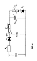
本開示のなお更なる観点は、プロセッサによって処理されるときに心臓センサ出力を処理する方法を含み、該心臓センサ出力は、感知された血圧、例えば感知された大動脈血圧又は心臓の左心室における感知された血圧、を含み、及び該処理が、動脈流モデルを用いて該心臓の血流量を導出することを含む。該動脈流モデルは、少なくとも下記によって表されるウィンドケッセル・モデルを含む:
− コンデンサーCW
− 該コンデンサーCWに並列に接続された抵抗Rp
− 該抵抗Rpと直列に接続されたツェナーダイオードZD
ここで、該コンデンサーCWの値は動脈コンプライアンスに関連付けられており、該抵抗Rpの値は抹消抵抗に関連付けられており、及びツェナーダイオードZDの値は血流量の背圧(back pressure)に関連付けられている。また、本開示のなお更なる観点は、該方法は、本明細書及び特許請求の範囲に記載の感知された血圧又はその該導出値から血流量を導出することをさらに含む。
A still further aspect of the present disclosure includes a method of processing cardiac sensor output when processed by a processor, wherein the cardiac sensor output is sensed blood pressure, eg sensed aortic blood pressure or sensed in the heart's left ventricle. And the processing includes deriving the blood flow of the heart using an arterial flow model. Artery flow model includes a Windkessel model represented by at least the following:
− Condenser C W
A resistor R p connected in parallel with the capacitor C W
A Zener diode Z D connected in series with the resistor R p
Here, the value of the capacitor C W is related to arterial compliance, the value of the resistance R p is related to the peripheral resistance, and the value of the Zener diode Z D is the back pressure of the blood flow. Associated with. Yet a further aspect of the present disclosure, the method further includes deriving blood flow from the sensed blood pressure or the derived value thereof as described in the specification and claims.
該動脈流モデルはさらに、既知の要素、例えば心臓の大動脈弁を表すダイオードD、及び該ダイオードと直列に接続され且つ心臓によって経験される非線形圧力インピーダンス表す電気的インピーダンスZ0の少なくとも1つ、を含みうる。 The arterial flow model further comprises at least one of known elements, for example, a diode D representing the aortic valve of the heart and an electrical impedance Z 0 connected in series with the diode and experienced by the heart and representing the non-linear pressure impedance. May be included.
該ツェナーダイオードを含むウィンドケッセル・モデルを使用する方法は、請求項1〜13に記載の方法と組み合わせて使用してもよく又は使用されなくてもよい。 The method of using the wind kessel model including the Zener diode may or may not be used in combination with the method of claims 1-13.
該ツェナーダイオードは、Maas等,Anesthesia & Analgesia 2012年;第1144巻:第803〜810頁により、ウォーターフォール(waterfall)現象として記載されている血流量の背圧を説明している。該背圧は、0〜50mmHgで変化しうる。該ウィンドケッセル・モデルにおける該背圧を含むことは、血流量を導出することにおける精度を改善する。1つの開示された実施態様において、該心臓に関連した腔が大動脈であり、及び該感知された血圧が、感知された大動脈血圧である。該方法はさらに、該心周期の拡張期段階の時間間隔の間の、該感知された大動脈血圧を抑制することによって、該感知された大動脈血圧の変更された大動脈血圧を得る工程を含む。該感知された大動脈血圧の抑制は、変更された大動脈血圧を得る為に、様々な様式において、例えば時間間隔の間の、該感知された大動脈血圧をゼロに設定することによって又は該感知された大動脈血圧の値を無視することによって達成されうる。該方法は、例えば、患者が該感知された血圧が関連する1心周期の間に作動しない大動脈に配置された心臓補助装置を有する場合に、有利に適用されうる。 The Zener diode describes the back pressure of blood flow described as a waterfall phenomenon by Maas et al., Anesthesia & Analgesia 2012; Volume 1144: 803-810. The back pressure can vary from 0 to 50 mmHg. Including the back pressure in the windkessel model improves the accuracy in deriving blood flow. In one disclosed embodiment, the chamber associated with the heart is the aorta and the sensed blood pressure is sensed aortic blood pressure. The method further during the time interval of the extended stages of said cardiac cycle, by suppressing the sensed aortic blood pressure, comprising the steps of obtaining a modified aortic blood pressure of said sensed aortic blood pressure. The sensed aortic blood pressure suppression, in order to obtain a modified aortic blood pressure in a variety of ways, such as during the time interval, also by setting the sensed aortic blood pressure to zero is the sensed It may be made reach by to ignore the value of aortic blood pressure. The method can be advantageously applied, for example, if the patient has a cardiac assist device placed in the aorta that does not operate during the cardiac cycle in which the sensed blood pressure is associated.
他の複数の心周期の間、該心臓補助装置は作動可能でありうる。従って、一つの実施態様において、該感知された大動脈血圧は、該1心周期の時間間隔の間に、心臓補助装置によって影響を受ける。典型的には、該心臓補助装置が血圧に影響を与える時間間隔は、該1心周期の拡張期の間の時間間隔である。該実施態様において、該シミュレートされた大動脈血圧を、該1心周期における該感知された大動脈血圧又はその変更された大動脈血圧と一致させることは、該時間間隔の外で実行される。該時間間隔の外の部分は、該心臓補助装置によって影響を受けない該1心周期の拡張期の間の部分でありうる。一つの実施態様において、該心臓補助装置が該感知された大動脈血圧に影響を与える時間間隔は、該心臓補助装置を監視することによって決定される(例えば、大動脈内バルーンにおける圧力)。該心臓補助装置は、該感知された大動脈血圧のどの部分(タイミング、持続時間)が抑制されるべきであるかを決定する為の信頼できる情報源である。 During other cardiac cycles, the cardiac assist device may be operable. Thus, in one embodiment, the sensed aortic blood pressure is affected by a cardiac assist device during the time interval of the one cardiac cycle. Typically, the time interval that the cardiac assist device affects blood pressure is the time interval during the diastole of the one cardiac cycle. In the embodiment, matching the simulated aortic blood pressure with the sensed aortic blood pressure in the one cardiac cycle or its altered aortic blood pressure is performed outside the time interval. The portion outside the time interval may be the portion during the diastole of the one cardiac cycle that is not affected by the cardiac assist device. In one embodiment, the time interval during which the cardiac assist device affects the sensed aortic blood pressure is determined by monitoring the cardiac assist device (eg, pressure in an intra-aortic balloon). The cardiac assist device is a reliable source for determining which part (timing, duration) of the sensed aortic blood pressure should be suppressed.
大動脈における血圧を感知する代わりに、血圧が心臓の左心室において感知されうる。この実施態様において、該感知された血圧は、左心室において感知された圧力である。 Instead of sensing blood pressure in the aorta, blood pressure can be sensed in the left ventricle of the heart. In this embodiment, the sensed blood pressure is the pressure sensed in the left ventricle.
一つの実施態様において、該方法は、該1心周期の終了時に、該シミュレートされた大動脈血圧を、該心臓の左心室における血圧に一致させる工程を含む。該1心周期の終了、例えば拡張期段階の終了、時は、心臓の左心室における感知された血圧の最も急な正の傾きを監視することから測定されうる。 In one embodiment, the method includes matching the simulated aortic blood pressure with the blood pressure in the left ventricle of the heart at the end of the one cardiac cycle. The end of the one cardiac cycle, such as the end of the diastolic phase, can be measured from monitoring the steepest positive slope of the sensed blood pressure in the left ventricle of the heart.
一つの実施態様において、該方法はさらに、該1心周期の拡張期段階の間の、該導出された血流量をゼロに設定することを含む。動脈のモデルに血流量を再導入する前に、該拡張期段階における該計算された血流量をゼロに設定することによって、より正確なシミュレートされた大動脈圧が得られる(例えば、血圧が大動脈において感知される場合に血流量効果を遅らせることを補償する)。 In one embodiment, the method further includes setting the derived blood flow to zero during the diastolic phase of the one cardiac cycle. Prior to reintroducing blood flow into the arterial model, a more accurate simulated aortic pressure can be obtained by setting the calculated blood flow in the diastolic phase to zero (eg, blood pressure is aorta Compensates for delaying blood flow effects when perceived in).
一つの実施態様において、該動脈流モデルはウィンドケッセル・モデルを含み、及び該動脈流パラメータの該値は動脈コンプライアンスに関連付けられたコンデンサー値CW及び抹消抵抗に関連付けられた抵抗値Rpを少なくとも含む。該ウィンドケッセル・モデルは、感知された血圧又はその導出値から血流量を導出することと該導出された血流量からシミュレートされた大動脈血圧を導出することとを可能にする。ウィンドケッセル動脈流パラメータの値の操作は、シミュレーション大動脈血圧を、該感知された血圧の一部又はその導出値と一致させることを可能にする。 In one embodiment, the arterial flow model comprises a Windkessel model, and the value of the arterial flow parameter comprises at least a capacitor value C W associated with arterial compliance and a resistance value R p associated with peripheral resistance. Including. The windkessel model makes it possible to derive a blood flow from the sensed blood pressure or its derived value and to derive a simulated aortic blood pressure from the derived blood flow. Manipulating the value of the Windkessel arterial flow parameter allows the simulated aortic blood pressure to match a portion of the sensed blood pressure or its derived value .
該ウィンドケッセル・モデルの複数の動脈流パラメータのうちの幾つかの値は、必ずしも一致させる操作の為に操作されない。一つの実施態様において、該コンデンサー値は、該1心周期に亘って、該変更された大動脈血圧を使用して得られる。該変更された大動脈血圧は、コンデンサー値を導出する為に、大動脈の断面積(CSA:cross sectional area)と組み合わせて使用されうる。該CSAは、エコー、コンダクタンス、又は他の測定を用いて決定されうる。この導出の為に、他の情報が必要とされることがあり、そのような患者データ(例えば、患者の年齢、性別、体重及び/又は身長)並びに血液の密度及び/又は導電率が使用されうる。該ウィンドケッセル・モデルが入力インピーダンスパラメータを含む場合には、このパラメータの値はまた、この段階で導出されうる。上記流パラメータは、他の様式、例えば大動脈の断面積と該変更された大動脈血圧との間の関係に対する1心周期の作業点のための固定された圧力値を用いることによって、導出されうる。 Some values of the arterial flow parameters of the windkessel model are not necessarily manipulated for matching operations. In one embodiment, the capacitor value is obtained using the altered aortic blood pressure over the one cardiac cycle. The altered aortic blood pressure can be used in combination with a cross sectional area (CSA) of the aorta to derive a capacitor value. The CSA can be determined using echo, conductance, or other measurements. Other information may be required for this derivation, such patient data (eg patient age, gender, weight and / or height) and blood density and / or conductivity are used. sell. If the windkessel model includes an input impedance parameter, the value of this parameter can also be derived at this stage. The flow parameters can be derived in other ways, for example by using a fixed pressure value for the working point of one cardiac cycle for the relationship between the cross-sectional area of the aorta and the altered aortic blood pressure.
本出願人は、一致させる操作の為に操作されうる1つのパラメータ値が抵抗値を含むことを見出した。従って、一つの実施態様において、少なくとも1回該抵抗値を操作して、該シミュレートされた大動脈血圧を、該1心周期における該感知された血圧の一部に一致させる工程を含み、該部分は好ましくは、該時間間隔の外である。上述された通り、該一致させる処理は反復処理であってもよく、該操作された抵抗値は、変更された大動脈血圧からの血流量を再び導出する為の入力として使用され、そこからさらにシミュレートされた大動脈の血流量が、感知された大動脈の血流量と一致させる為に導出される。反復の回数nは、2〜10、好ましくは2〜5、でありうる。良好な結果が、n=3,4,5,6及び7について得られた。 The Applicant has found that one parameter value that can be manipulated for the matching operation includes a resistance value. Thus, in one embodiment, manipulating the resistance value at least once to match the simulated aortic blood pressure to a portion of the sensed blood pressure in the one cardiac cycle, Is preferably outside the time interval. As described above, the matching process may be an iterative process, and the manipulated resistance value is used as an input to again derive blood flow from the modified aortic blood pressure, from which further simulations are made. The measured aortic blood flow is derived to match the sensed aortic blood flow. The number of iterations n can be 2-10, preferably 2-5. Good results were obtained for n = 3, 4, 5, 6 and 7.
一つの実施態様において、初期抵抗値は、以前の1心周期、例えば先行する1心周期、において得られた抵抗値に対応する。 In one embodiment, the initial resistance value corresponds to the resistance value obtained in a previous cardiac cycle, eg, a preceding cardiac cycle.
上述された通り、心臓センサの処理された出力は、他の装置、例えば患者監視装置又は心臓補助装置、の入力として使用されうる。例は、下記を含む:
− 該1心周期に亘って、該一致されたシミュレートされた大動脈血圧及び/又はその特性値を出力すること、例えば表示すること;
− 該動脈流パラメータの操作された値の少なくとも1つを出力すること、例えば表示すること;
− 該動脈流パラメータの操作された値の少なくとも1つを少なくとも用いて心臓補助装置を制御すること;
− 該使用された動脈流パラメータを用いて、心臓の一回心拍出量を決定すること。
As described above, the processed output of the heart sensor can be used as input for other devices, such as a patient monitoring device or a cardiac assist device. Examples include:
Outputting, eg displaying, the matched simulated aortic blood pressure and / or its characteristic value over the one cardiac cycle;
Outputting, eg displaying, at least one of the manipulated values of the arterial flow parameter;
-Controlling the cardiac assist device with at least one of the manipulated values of the arterial flow parameter;
Using the used arterial flow parameters to determine the cardiac output of the heart.
当業者によって理解されるであろう通り、本開示の1以上の工程は、システム、方法、又はコンピュータ・プログラム製品として具現化されうる。従って、本発明の観点は、完全にハードウェアの実施態様、完全にソフトウェアの実施態様(ファームウェア、常駐ソフトウェア、マイクロコードなどを含む)、又は本明細書において「回路」、「モジュール」若しくは「システム」として全て一般的に呼ばれうるソフトウェア及びハードウェアの観点を組み合わせた実施形態の形をとりうる。本開示で記載される機能は、コンピュータのプロセッサ/マイクロプロセッサによって実行されるアルゴリズムとして実装されうる。その上、本開示の観点は、例えば1以上のコンピュータ読み取り可能な媒体上に具現化された、例えばその上に記憶された、コンピュータ読み取り可能なプログラム・コードを有する1以上のコンピュータ読み取り可能な媒体に具現化されたコンピュータ・プログラム製品の形を取りうる。 As will be appreciated by one skilled in the art, one or more steps of the present disclosure may be embodied as a system, method, or computer program product. Accordingly, an aspect of the present invention is a fully hardware implementation, a fully software implementation (including firmware, resident software, microcode, etc.), or a “circuit”, “module” or “system” herein. Can take the form of an embodiment that combines software and hardware aspects, all of which can be generally referred to as. The functions described in this disclosure may be implemented as an algorithm executed by the processor / microprocessor of the computer. Moreover, aspects of the disclosure may be implemented on, for example, one or more computer-readable media, such as one or more computer-readable media having computer-readable program code stored thereon. It can take the form of a computer program product embodied in
1以上のコンピュータ読み取り可能な体の任意の組み合わせが利用されうる。該コンピュータ読み取り可能な媒体は、コンピュータ読み取り可能な信号媒体又はコンピュータ読み取り可能な記憶媒体でありうる。コンピュータ読み取り可能な記憶媒体は例えば、電子、磁気、光学、電磁気、赤外線、若しくは半導体のシステム、装置、若しくはデバイス、又はこれらの任意の適切な組み合わせでありうるが、これらに限定されない。コンピュータ読み取り可能な記憶媒体のより具体的な例は、下記を含みうるが、これらに限定されない:1つ以上の線を有する電気的接続、ポータブル・コンピュータ・ディスケット、ハードディスク、ランダム・アクセス・メモリ(RAM)、読み出し専用メモリ(ROM)、消去可能なプログラム可能な読み出し専用メモリ(EPROM 又はフラッシュメモリ)、光ファイバ、ポータブルコンパクトディスク読み出し専用メモリ(CD-ROM)、光記憶装置、磁気記憶装置、又は上記の任意の適切な組み合わせ。本発明の文脈において、コンピュータ読み取り可能な記憶媒体は、命令実行システム、装置、若しくはデバイスによって又は命令実行システム、装置、若しくはデバイスと組み合わせて使用する為のプログラムを含む又は記憶することができる任意の有形媒体でありうる。 Any combination of one or more computer readable bodies may be utilized. The computer readable medium may be a computer readable signal medium or a computer readable storage medium. The computer readable storage medium can be, for example but not limited to, an electronic, magnetic, optical, electromagnetic, infrared, or semiconductor system, apparatus, or device, or any suitable combination thereof. More specific examples of computer readable storage media may include, but are not limited to: electrical connections having one or more lines, portable computer diskettes, hard disks, random access memory ( RAM), read-only memory (ROM), erasable programmable read-only memory (EPROM or flash memory), optical fiber, portable compact disk read-only memory (CD-ROM), optical storage device, magnetic storage device, or Any suitable combination of the above. In the context of the present invention, a computer readable storage medium includes any program that can contain or store a program for use by or in combination with an instruction execution system, apparatus, or device. It can be a tangible medium.
コンピュータ読み取り可能な信号媒体は、例えば、ベースバンド中に又は搬送波の一部として具現化されたコンピュータ可読プログラム・コードを有する伝搬されたデータ信号を含みうる。そのような伝播された信号は、任意の様々な形、例えば電磁気、光学、又はそれらの任意の適切な組み合わせ、を含みうるが、これらに限定されない。コンピュータ読み取り可能な信号媒体は、コンピュータ読み取り可能な記憶媒体でなく且つ命令実行システム、装置、又はデバイスによって又は命令実行システム、装置、若しくはデバイスと組み合わせて使用する為のプログラムを通信し、伝播し又は転送することができる任意のコンピュータ読み取り可能な媒体でありうる。 A computer readable signal medium may include a propagated data signal with computer readable program code embodied therein, for example, in baseband or as part of a carrier wave. Such propagated signals can include, but are not limited to, any of a variety of forms, such as electromagnetic, optical, or any suitable combination thereof. A computer-readable signal medium is not a computer-readable storage medium and communicates, propagates, or transmits a program for use by or in combination with an instruction execution system, apparatus, or device It can be any computer-readable medium that can be transferred.
コンピュータ読み取り可能な媒体上に具現化されたプログラム・コードは、任意の適切な媒体、例えば無線、有線、光ファイバ、ケーブル、RFなど、又はこれらの任意の適切な組み合わせを含むがこれらに限定されない、を使用して送信されうる。本発明の観点の為の動作を実行するためのコンピュータ・プログラム・コードは、1以上のプログラミング言語、例えばオブジェクト指向プログラミング言語、例えばJava(商標)、Smalltalk、C++など、及び従来の手続き型プログラミング言語、例えば「C」プログラミング言語又は同様のプログラミング言語、の任意の組み合わせにおいて書かれうる。該プログラム・コードは、完全にユーザのコンピュータ上で、部分的にユーザのコンピュータ上で、スタンドアロンのソフトウェアパッケージとして、部分的にユーザのコンピュータ且つ部分的にリモート・コンピュータ上で、又は完全にリモート・コンピュータ若しくはサーバ上で実行しうる。後者のシナリオでは、該リモート・コンピュータは、任意のタイプのネットワーク、例えばローカルエリアネットワーク(LAN)若しくはワイドエリアネットワーク(WAN)、を通じてユーザのコンピュータに接続されてもよく、又は該接続は、(例えばインターネットサービスプロバイダを用いるインターネットを通じて)外部コンピュータに接続されうる。 Program code embodied on a computer readable medium includes, but is not limited to, any suitable medium, such as wireless, wired, optical fiber, cable, RF, etc., or any suitable combination thereof. , Can be transmitted using. Computer program code for performing operations for aspects of the present invention may include one or more programming languages, such as object-oriented programming languages such as Java ™, Smalltalk, C ++, and conventional procedural programming languages Can be written in any combination of, for example, the “C” programming language or similar programming languages. The program code may be stored entirely on the user's computer, partially on the user's computer, as a stand-alone software package, partially on the user's computer and partially on the remote computer, or completely on the remote computer. It can run on a computer or server. In the latter scenario, the remote computer may be connected to the user's computer through any type of network, such as a local area network (LAN) or a wide area network (WAN), or the connection may be (for example, It can be connected to an external computer (via the Internet using an Internet service provider).
本発明の観点は、本発明の実施態様に従う方法、装置(システム)及びコンピュータ・プログラム製品のフローチャート図及び/又はブロック図を参照して以下に説明される。フローチャート図及び/又はブロック図の各ブロック並びにフローチャート図及び/又はブロック図におけるブロックの組み合わせがコンピュータ・プログラム命令によって実装されることができることが理解できるであろう。これらのコンピュータ・プログラム命令は、汎用コンピュータ、特殊目的コンピュータ、又は他のプログラム可能なデータ処理装置のプロセッサ、特にマイクロプロセッサ又は中央処理装置(CPU)、に提供されて、機械を製造してもよく、従って該コンピュータ、他のプログラム可能なデータ処理装置、又は他の装置の該プロセッサを介して実行される命令が、フローチャート及び/又はブロック図の1以上のブロックにおいて指定された機能/動作を実装する為の手段を生成する。 Aspects of the invention are described below with reference to flowchart illustrations and / or block diagrams of methods, apparatus (systems) and computer program products according to embodiments of the invention. It will be understood that each block of the flowchart illustrations and / or block diagrams, and combinations of blocks in the flowchart illustrations and / or block diagrams, can be implemented by computer program instructions. These computer program instructions may be provided to a processor of a general purpose computer, special purpose computer, or other programmable data processing device, particularly a microprocessor or central processing unit (CPU), to manufacture the machine. Thus, instructions executed via the processor of the computer, other programmable data processing device, or other device implement functions / operations specified in one or more blocks of the flowcharts and / or block diagrams. Generate means to do.
これらのコンピュータ・プログラム命令はまた、コンピュータ、他のプログラム可能なデータ処理装置、又は他のデバイスを指示して特定の様式において機能することができるコンピュータ読み取り可能な記憶媒体中に記憶されてもよく、従ってコンピュータ読み取り可能な記憶媒体中に記憶された命令は、フローチャート及び/又はブロック図の1以上のブロックにおいて指定された機能/動作を実装する命令を含む製品を製造する。 These computer program instructions may also be stored in a computer readable storage medium that can direct a computer, other programmable data processing apparatus, or other device to function in a particular fashion. Thus, instructions stored in a computer readable storage medium produce a product that includes instructions that implement the functions / operations specified in one or more blocks of the flowcharts and / or block diagrams.
該コンピュータ・プログラム命令はまた、コンピュータ、他のプログラム可能なデータ処理装置、又は他のデバイス上にロードされて、該コンピュータ、他のプログラム可能なデータ処理装置、又は他のデバイス上で実行されるべき一連の操作工程を生じて、コンピュータ実装されたプロセスを生成してもよく、従ってコンピュータ又は他のプログラム可能なデータ処理装置上で実行する該命令はフローチャート及び/又はブロック図の1以上のブロックにおいて指定された機能/動作を実装する為のプロセスを提供する。 The computer program instructions are also loaded on a computer, other programmable data processing device, or other device and executed on the computer, other programmable data processing device, or other device. May generate a sequence of operational steps to generate a computer-implemented process, so that the instructions for execution on a computer or other programmable data processing device are one or more blocks of a flowchart and / or block diagram Provides a process for implementing the functions / operations specified in.
図面におけるフローチャート及びブロック図は、本発明の様々な実施態様に従うシステム、方法及びコンピュータ・プログラム製品のありうる実装のアーキテクチャ、機能、及び動作を示す。これに関して、フローチャート又はブロック図における各ブロックは、特定1以上の論理機能を実装するための1以上の実行可能な命令を含むモジュール、セグメント、又はコード部分を表しうる。幾つかの代替の実施形態において、ブロックに記載されている機能は、図に記載されている順序から外れることがありうることにもまた留意されたい。例えば、連続して示される2つのブロックが、実際には実質的に同時に実行されてもよく、又は該ブロックが、関連する機能に依存して時々逆の順序で実行されてもよい。ブロック図及び/又はフローチャート図における各ブロック並びにブロック図及び/又はフローチャート図における複数のブロックの組み合わせが、特定の機能又は動作を実行する専用のハードウェアベースのシステムによって又は専用ハードウェアとコンピュータ命令との組み合わせによって実装されることができる。 The flowchart and block diagrams in the Figures illustrate the architecture, functionality, and operation of possible implementations of systems, methods and computer program products according to various embodiments of the present invention. In this regard, each block in the flowchart or block diagram may represent a module, segment, or code portion that includes one or more executable instructions for implementing a particular one or more logical functions. It should also be noted that in some alternative embodiments, the functions described in the blocks may be out of the order described in the figures. For example, two blocks shown in succession may actually be executed substantially simultaneously, or the blocks may be executed in reverse order from time to time depending on the functions involved. Each block in the block diagrams and / or flowchart diagrams, and combinations of blocks in the block diagrams and / or flowchart diagrams, can be implemented by a dedicated hardware-based system that performs a specific function or operation, or Can be implemented by a combination of
本発明の実施態様はさらに、本発明に従う実施形態を概略的に示す添付の図面を参照して説明されるだろう。本発明は、これらの特定の実施態様に決して限定されないことが理解されるであろう。 Embodiments of the present invention will be further described with reference to the accompanying drawings, which schematically show embodiments according to the present invention. It will be understood that the invention is in no way limited to these specific embodiments.
本発明は特許請求の範囲に記載された特徴の全てのありうる組み合わせに関することに注目される。 It is noted that the invention relates to all possible combinations of the features recited in the claims.
本発明の観点は、図面に示されている例示的な実施態様を参照してより詳細に説明されるだろう。 Aspects of the invention will be described in greater detail with reference to the exemplary embodiments shown in the drawings.
図1A〜図1Cは、本発明の実施態様に従う心臓センサ出力を得て処理するように構成されたコンピュータ・システム1の概略図を示す。コンピュータ・システムのそれぞれは、本明細書において開示されている通りの、心臓センサ出力を処理する為の命令を実行するように構成されたメモリ2及びプロセッサ3を少なくとも含む。図8、14及び15並びに対応する記載は、コンピュータ・システム1についての更なる詳細を提供する。
1A-1C show a schematic diagram of a
図1Aは、心臓に関連した腔C、例えば大動脈又は心臓の心室、を示し、心臓センサ4が挿入される。心臓センサ4は、感知された血圧を得る為に時間tの関数として、該大動脈における圧力Pao(t)又は心臓の左心室における圧力Plv(t)を連続的に感知する。該感知された血圧は、更なる処理の為にコンピュータ・システム1に出力される。
FIG. 1A shows a cavity C associated with the heart, such as the aorta or heart ventricle, with the
図1Bは、コンピュータ・システム1が処理結果を表示する為のモニターMに接続されている同様の状況を示す。モニターMは、コンピュータ・システム1と一体化されていてもよく、又はコンピュータ・システム1から離れて配置されていてもよい。心臓補助装置5、例えば大動脈内バルーンIAB(intra-aorta balloon)、が、腔C内に配置されうる。心臓補助装置5は、心臓補助コントローラ6によって制御される。心臓補助コントローラ6は、IABの為の圧力PIABを提供する圧力発生器を含みうる。心臓補助コントローラ6又はその一部は、コンピュータ・システム1と一体化されうる。
FIG. 1B shows a similar situation where the
図1Cの配置において、コンピュータ・システム1は、心臓補助コントローラ6と接続されている。コンピュータ・システム1は心臓補助コントローラ6から情報を受信してもよく、及びコンピュータ・システム1からの処理結果が心臓補助コントローラ6を制御する為に使用されてもよい。そのような配置のより詳細な説明が、図10を参照して以下に記載されている。再び、心臓補助コントローラ6は、コンピュータ・システム1と一体化されていてもよい。
In the arrangement of FIG. 1C, the
大動脈血圧Paoは、大動脈Cの上昇部分に配置された任意のカテーテルで、好ましくは該カテーテルの頂部に取り付けられた又は該カテーテルの前に配置された高忠実度の圧力変換器で、測定されうる。 Aortic blood pressure Pao can be measured with any catheter placed in the elevated portion of aorta C, preferably with a high fidelity pressure transducer attached to the top of the catheter or placed in front of the catheter. .
大動脈におけるPaoを測定するのではなく、大動脈圧Paoに比例するか又は大動脈圧Paoに変換されることができる任意の他の信号又は動脈圧、例えば上腕動脈で測定された圧力又は他のより周辺の圧力、が使用されうる。次に、本発明において記載されている通りの計算を実行する為に必要とされる幾つかの点のいずれか又は全てにおいて、必要とされるスケーリング又は変換が行うれうる。測定された信号は、関心のある時間間隔に亘って、大動脈圧Paoと等しいか又は少なくとも既知の関係を有する。そのような信号の一例は、図12〜14を参照して更に説明されるであろう通り、心臓の左心室において測定された圧力Plvでありうる。 Rather than measuring Pao in the aorta, any other signal or arterial pressure that is proportional to or can be converted to aortic pressure Pao, such as the pressure measured in brachial artery or other more peripheral Can be used. The required scaling or transformation can then be performed at any or all of the several points required to perform the calculations as described in the present invention. The measured signal is equal to or at least has a known relationship with the aortic pressure Pao over the time interval of interest. An example of such a signal may be a pressure Plv measured in the left ventricle of the heart, as will be further described with reference to FIGS.
図2の上の図は、単一の心臓拍動、すなわち1心周期、に亘る感知された大動脈圧Paoを示す。該1心周期を通じて、血圧が増加し、そして減少する。各心周期は2つの主要な段階、すなわち収縮期段階及び拡張期段階、を含む。 The upper diagram of FIG. 2 shows the sensed aortic pressure Pao over a single heart beat, ie one cardiac cycle. Through the one cardiac cycle, blood pressure increases and decreases. Each cardiac cycle includes two major phases: a systolic phase and a diastolic phase.
該収縮期段階は、心臓の収縮期に関連する。心臓の拡張期段階は、心臓が循環血液を補充する準備において弛緩する期間である。該心周期の全体に亘る大動脈圧のグラフは、重複切痕(dicrotic notch)として言及される小さな陥没を示し、それは大動脈弁閉鎖と一致する。該グラフにおける該陥没は、直ちに短時間上昇し(「重拍波」)、そして次に徐々に減少する。該心室が拡張期に入るとたんに、大動脈から左心室に向かって短時間逆流することは、大動脈弁が閉鎖することを生じる。これは、半月弁及び大動脈の弾性反跳によって生じる大動脈圧におけるわずかな増加を結果として生じる。 The systolic phase is associated with the systolic phase of the heart. The diastolic phase of the heart is the period during which the heart relaxes in preparation for replenishing circulating blood. A graph of aortic pressure throughout the cardiac cycle shows a small depression referred to as a dicrotic notch, which is consistent with aortic valve closure. The depression in the graph immediately rises for a short time ("heavy beat") and then gradually decreases. As soon as the ventricle enters diastole, a brief back flow from the aorta to the left ventricle results in the aortic valve closing. This results in a slight increase in aortic pressure caused by the meniscal valve and elastic recoil of the aorta.
該感知された大動脈圧Paoから、該感知された大動脈圧に対応する血流量を導出することが一般的である。該1心周期の間の血流量の例が、図2の下の図に示されている。 In general, the blood flow volume corresponding to the sensed aortic pressure is derived from the sensed aortic pressure Pao. An example of blood flow during the one cardiac cycle is shown in the lower diagram of FIG.
血流量を導出する為の1つの既知の様式は、動脈流モデル、例えばウィンドケッセル・モデル、によるものである。該ウィンドケッセル・モデルは、解剖学的構成要素、例えば左心室、大動脈弁、動脈の血管系及び抹消流れ経路、をモデル化する。これらの構成要素は、動脈流パラメータによって表される。 One known manner for deriving blood flow is by an arterial flow model, such as a windkessel model. The windkessel model models anatomical components such as the left ventricle, aortic valve, arterial vasculature and peripheral flow pathways. These components are represented by arterial flow parameters.
そのようなシステムを表すアナログモデルは、大動脈弁を表すダイオードDと組み合わせて、単一の能動性の流パラメータ(コンデンサーCW)及び単一の受動性の流パラメータ(抵抗)を有する。そのようなシステムは、心拍の拡張期段階の間の動脈圧Pao(t)における単一の指数関数的減衰を説明のみする。 An analog model representing such a system has a single active flow parameter (capacitor C W ) and a single passive flow parameter (resistance) in combination with a diode D representing an aortic valve. Such a system only accounts for a single exponential decay in arterial pressure Pao (t) during the diastolic phase of the heartbeat.
この2要素モデルに対する改良は、図3に示されている通り、人間の大動脈において測定された収縮期圧及び拡張期圧減衰のより良い記述を結果として生じる3要素モデルである。流量q(t)を導出する為に、該モデルは、2つの能動性の要素、すなわち、コンデンサーCWによって表される依存性コンプライアンス及び特性インピーダンスZ0によって表される血液の圧力依存慣性、と、RPによって表される全身血管抵抗である1つの受動性の要素とを含む。心臓補助装置を制御する為にこのモデルを使用する例が、米国特許出願公開第2004/0059183号明細書に開示されている。 The improvement to this two- element model is a three- element model that results in a better description of the systolic and diastolic pressure decay measured in the human aorta, as shown in FIG. In order to derive the flow rate q (t), the model consists of two active components: the dependency compliance represented by the capacitor C W and the pressure dependent inertia of the blood represented by the characteristic impedance Z 0 , and One passive component that is the systemic vascular resistance represented by R P. An example of using this model to control a cardiac assist device is disclosed in US 2004/0059183.
近年、既知の3要素のウィンドケッセル・モデルの全てにおいて仮定されている通り、末梢循環への血流量に対する背圧がゼロに等しくないことが判っている。本開示は、図4に示されている通り、ツェナーダイオードZDによって該ウィンドケッセル・モデルにおけるこの背圧を実装することを今提案する。 Recently, as is assumed in all the Windkessel model of known three elements, back pressure against the blood flow to the peripheral circulation are found to be not equal to zero. The present disclosure now proposes to implement this back pressure in the windkessel model by means of a Zener diode Z D as shown in FIG.
ツェナーダイオードZDは、Maas等によるウォーターフォール(waterfall)現象として記載された血流量の背圧を説明している。該背圧は、0〜50mmHgで変動しうる。 Zener diode Z D explains the back pressure of blood flow described as a waterfall phenomenon by Maas et al. The back pressure can vary from 0 to 50 mmHg.
ウィンドケッセル・モデルに該背圧を含めることは、血流量q(t)を導出する際の精度を向上させる。 Including the back pressure in the wind Kessel model improves the accuracy in deriving the blood flow q (t).
図3及び図4に示されている場合のウィンドケッセル・モデルはまた、左心室圧Plv(t)が感知されるときに使用されうる。Plv(t)が感知される場合、流れ抵抗Rvは、左心室と大動脈との間の大動脈弁の流れ抵抗を表すために使用される。Rvの値は文献から既知である。 The windkessel model as shown in FIGS. 3 and 4 can also be used when left ventricular pressure Plv (t) is sensed. If PLV (t) is sensed, the flow resistance R v is used to represent the flow resistance of the aortic valve between the left ventricle and the aorta. The value of R v are known from the literature.
図5は、血流量q(t)を導出する際の幾つかの工程を示す。工程S1において、大動脈圧Pao(t)が、大動脈における圧力センサ4を用いて感知される。同様に、左心室圧Plv(t) が、心臓の左心室において感知されうる。
FIG. 5 shows several steps in deriving the blood flow rate q (t). In step S1, the aortic pressure Pao (t) is sensed using the
工程S2において、図4のツェナーダイオードZDを含むウィンドケッセル動脈流モデルが施与される。工程S3において、血流量q(t)が得られる。感知された大動脈圧Pao(t)又は感知された左心室圧Plv(t)から血流量q(t)を導出する為にウィンドケッセル・モデルを用いるコンピュータ・システム1の例が図1Aに示されている。
In step S2, Windkessel arterial flow model including a Zener diode Z D in FIG. 4 is applied. In step S3, a blood flow rate q (t) is obtained. An example of a
本開示の一実施形態は大動脈血圧を感知することに関し、該大動脈血圧は、心臓補助装置によって影響される。この実施態様は、図6A〜6D及び図7〜10を参照して今記載されるだろう。 One embodiment of the present disclosure relates to sensing aortic blood pressure, which is affected by a cardiac assist device. This embodiment will now be described with reference to Figures 6A-6D and Figures 7-10.
図2は、図1Aの状況における単一の心周期についての大動脈血圧Pao(t)の測定を示す。前述されている通り、心臓補助装置6の動作は、圧力測定に深刻な影響を与えるだろう。
FIG. 2 shows the measurement of aortic blood pressure Pao (t) for a single cardiac cycle in the situation of FIG. 1A. As previously mentioned, the operation of the
図6Aは、単一の心周期についての感知された大動脈血圧Paoの概略図を示し、心臓補助装置5は動脈内バルーンIABを含む。明らかに、該IABは、該心周期の拡張期段階の圧力に影響を与える。 FIG. 6A shows a schematic diagram of the sensed aortic blood pressure Pao for a single cardiac cycle, and the cardiac assist device 5 includes an intra-arterial balloon IAB. Apparently, the IAB affects the pressure during the diastolic phase of the cardiac cycle.
通常の膨張−収縮タイミングにおいて、バルーン膨張は、大動脈弁閉鎖後の拡張期の開始時に生じ;収縮は、大動脈弁が開く直前の拡張期の後期に起こる。適切に時限を設定されると、膨張ポイントは、重複切痕に位置するか、又はわずかに後ろに位置する。 At normal inflation-deflation timing, balloon inflation occurs at the beginning of diastole after aortic valve closure; deflation occurs late in diastole just before the aortic valve opens. When properly timed, the inflation point is located at the overlap notch or slightly behind.
特に、該心周期についての大動脈圧を感知することは、収縮期段階及び拡張期段階を含む。該収縮期段階の開始時に、感知された圧力は、以前の1心周期の拡張期段階の終わりでの圧力、すなわち時間tdia0でのPdia0、に対応する。該1心周期の終わりに、該感知された圧力は時間tdia1でのPdia1に対応する。該1心周期の収縮期段階は、tdia0からtsysまでの時間間隔に亘っており、Psysはこの間隔の間に最高の大動脈圧である。該拡張期段階は、tsysからtdia1までの時間間隔にわたる。該IABが大動脈圧に影響を与える1心周期の時間間隔は、図6Aにおいて「増大」で示されており、且つta0(重複切痕の直後)からta1までの時間間隔にわたる。該拡張期段階の間、部分ta1〜tdia1の圧力は該IABによって増大されない。 In particular, sensing aortic pressure for the cardiac cycle includes a systolic phase and a diastolic phase. At the beginning of the systolic phase, the sensed pressure corresponds to the pressure at the end of the previous diastolic phase of one cardiac cycle, ie Pdia0 at time tdia0. At the end of the one cardiac cycle, the sensed pressure corresponds to Pdia1 at time tdia1. The systolic phase of the one cardiac cycle spans the time interval from tdia0 to tsys, where Psys is the highest aortic pressure during this interval. The diastolic phase spans the time interval from tsys to tdia1. The time interval of one cardiac cycle at which the IAB affects aortic pressure is shown as “increase” in FIG. 6A and spans the time interval from ta0 (immediately after the double notch) to ta1. During the diastolic phase, the pressure in the parts ta1 to tdia1 is not increased by the IAB.
時間の関数としての大動脈圧の感知又は導出は、図7において工程S10として示され、且つ図8のシステム図の左上隅に示されている。心拍数HRは、60/(tdia1-tdia0)として計算されることができる。 Sensing or deriving aortic pressure as a function of time is shown as step S10 in FIG. 7 and in the upper left corner of the system diagram of FIG. The heart rate HR can be calculated as 60 / (tdia1-tdia0).
第2の工程S11において、変更された大動脈圧Paoは、図6Bにおいて示されている通り、1心周期に亘って得られる。変更された大動脈圧Paoは、コンピュータ・システム1において該感知された大動脈圧Paoを処理することによって導出される。特に、コンピュータ・システム1は、Paoが増大される時間間隔、すなわち拡張期段階の時間間隔ta0〜ta1、に亘って値を抑制することによって又はPaoの値をゼロに設定することによって、1心周期の時間間隔の間の該感知された大動脈血圧を抑制しうる。該心臓補助装置は、該感知された大動脈血圧のどの部分(タイミング、持続時間)が抑制されるべきかを決定する為の信頼できる情報源である。
In the second step S11, the changed aortic pressure Pao is obtained over one cardiac cycle as shown in FIG. 6B. The modified aortic pressure Pao is derived by processing the sensed aortic pressure Pao in the
様々な直接的且つ間接的方法が、時間間隔ta0〜ta1を識別するために使用されうる。一つの実施態様において、圧力PIABが測定され、そして該時間間隔ta0〜ta1と相関される。一旦該時間間隔tao〜ta1が決定されると、該変更された大動脈血圧が得られることができる。 Various direct and indirect methods can be used to identify the time intervals ta0-ta1. In one embodiment, the pressure P IAB is measured and correlated with said time interval Ta0~ta1. Once the time interval tao-ta1 is determined, the altered aortic blood pressure can be obtained.
第3の工程S12において、血流量q(t)が、図3及び図4において示されている通りの動脈流モデルを用いて、該変更された大動脈圧から得られる。動脈流モデルは、動脈圧と血流量との間の関係を提供するモデルを含む。 In the third step S12, the blood flow q (t) is obtained from the altered aortic pressure using the arterial flow model as shown in FIGS. Arterial flow models include models that provide a relationship between arterial pressure and blood flow.
図3を参照して上述されたウィンドケッセル・モデルが該動脈流モデルについて採用される場合、下記の数式が適用される: When the wind kessel model described above with reference to FIG. 3 is employed for the arterial flow model, the following formula applies:

ここで、dq(t)/dt及びdPao(t)/dtは、血流量q(t)及び感知された大動脈血圧Pao(t)の一次時間微分係数であり、且つZ0、CW及びRPは動脈流パラメータである。 Where dq (t) / dt and dPao (t) / dt are the primary time derivatives of blood flow q (t) and sensed aortic blood pressure Pao (t), and Z 0 , C W and R P is an arterial flow parameter.
図4のウィンドケッセル・モデルが使用される場合、下記の関係が適用される: If the windkessel model of Figure 4 is used, the following relationship applies:
該変更された大動脈血圧は、図8の左下隅に示される通り、上記流パラメータZ0及びCWの計算の為の入力として用いられうる。時間変動するZ0及びCW は、大動脈の断面積CSAに依存し、及び例えば、Langewouters等,J.Biomechanics (1984年) 第17巻,第425〜434頁の逆正接モデルを用いて推定されうる。 The modified aortic blood pressure can be used as an input for the calculation of the flow parameters Z 0 and C W as shown in the lower left corner of FIG. Time-varying Z 0 and C W depend on the cross-sectional area CSA of the aorta and are described in, for example, Langewouters et al. It can be estimated using the arc tangent model of Biomechanics (1984) Vol. 17, pp. 425-434.
更なる入力情報は、患者に関連する入力(年齢、性別、身長、体重)及び較正係数を含みうる。この情報は、図9において示されている通り、大動脈の断面積CSA及び圧力Pao(t)の依存性を得るために使用されうる。この依存性を得る1つの方法が、米国特許出願公開第2008/0208062号明細書に記載されている。CSA 対 圧力関係に対する作業点Pao(t)から、Z0及びCWの圧力依存値が、例えば米国特許出願公開第2008/0208062号明細書において記載された通りに得られる。 Further input information may include patient related inputs (age, gender, height, weight) and calibration factors. This information can be used to obtain the dependence of the aortic cross-sectional area CSA and pressure Pao (t), as shown in FIG. One way to obtain this dependency is described in US Patent Application Publication No. 2008/0208062. From the working point Pao (t) for the CSA versus pressure relationship, pressure dependent values of Z 0 and C W are obtained, for example, as described in US 2008/0208062.
Murgo及びWesterhof,Circ.Res.(1984年) 第54巻:第666〜673頁は、下記の通り、特性入力抵抗Z0を導出する: Murgo and Westerhof, Circ. Res. (1984) Volume 54: Pages 666-673 derive the characteristic input resistance Z 0 as follows:
ここで、ρは血液の密度であり、CSAは圧力Paoでの大動脈の断面積であり、及びC'Wは測定された圧力Paoでの圧力/CSA関係の一次微分係数の値である。 Where ρ is the blood density, CSA is the cross-sectional area of the aorta at pressure Pao, and C ′ W is the value of the first derivative of the pressure / CSA relationship at the measured pressure Pao.
動脈コンプライアンスCwは、C'Wに患者の動脈系の有効長を乗じることによって見つけられる。有効長について、通常、患者の身長の半分が選ばれる。Cwは、大動脈圧が増加するときに実質的に減少する。大動脈壁のこの非線形挙動は、上記された通りの様式において考慮されない場合に、誤差の大きな原因でありうる。 Arterial compliance C w is found by multiplying the effective length of the arterial system of a patient to C 'W. For the effective length, half of the patient's height is usually chosen. C w is substantially reduced when the aortic pressure is increased. This non-linear behavior of the aortic wall can be a significant source of error if not taken into account in the manner as described above.
上記流パラメータZ0及びCWは、他の様式において、例えば大動脈の断面積と該変更された大動脈血圧との間の関係に対する作業点についての固定された圧力値を用いることによって、導出されうる。1つの例は、該作業点として、(収縮期圧+2*拡張期圧)/3を計算し、そしてZ0及びCWについての固定値を計算することによって平均圧値を導出することを含む。 The flow parameters Z 0 and C W can be derived in other ways, for example by using a fixed pressure value for the working point for the relationship between the cross-sectional area of the aorta and the altered aortic blood pressure. . One example involves calculating the mean pressure value by calculating (systolic pressure + 2 * diastolic pressure) / 3 as the working point and calculating fixed values for Z 0 and C W .
大動脈流パラメータRPは、図8に示されている通り、以前の1心周期、Rpini、から取得されうる。Rpの値は、1心周期の間又は複数のサイクルに亘って動脈の血管系内に流れる血液の総量がまた該動脈の血管系から再び流れるであろうと仮定することによって計算されることができる。換言すれば、q(t)=0は、1心周期の終わりに到着するq(t)の値である。 The aortic flow parameter R P can be obtained from the previous one cardiac cycle, Rp ini , as shown in FIG. The value of Rp can be calculated by assuming that the total amount of blood flowing into the arterial vasculature during one cardiac cycle or over multiple cycles will also flow again from the arterial vasculature . In other words, q (t) = 0 is the value of q (t) that arrives at the end of one cardiac cycle.
大動脈流量パラメータについてのこのように決定された値を用いて、血流量、q(t)、についての値が式(1)又は式(2)によって導出されることができる。心臓弁の閉鎖時間は、心臓の排出段階の開始後の最初の極小の時間を決定することによって計算された血流量から正確に導出されることができる。 Using the value thus determined for the aortic flow parameter, a value for blood flow, q (t), can be derived by equation (1) or equation (2). The closure time of the heart valve can be accurately derived from the blood flow calculated by determining the initial minimum time after the beginning of the cardiac drainage phase.
該変更された大動脈圧、動脈の血流量モデル及び決定された動脈流パラメータから導出された血流量が、図6Cにおいて示されている。該導出された血流量は、遅延作用を説明する為に拡張期段階の間にゼロに設定される。 The blood flow derived from the altered aortic pressure, the arterial blood flow model and the determined arterial flow parameters is shown in FIG. 6C. The derived blood flow is set to zero during the diastolic phase to account for the delayed action.
シミュレートされた血流量から、一回心拍出量SVは図8において示されている通りに決定されうる。このようにして得られた一回拍出量SVに心拍数HRを乗算することにより、心拍出量COは、図8においてまた示されている通りに導出されることができる。心拍数HR及び/又は心拍出量COは、図8においてまた示されている通り出力されうる。出力HR及びCOは、図1BのモニターM上に示されうる。 From the simulated blood flow, the stroke volume SV can be determined as shown in FIG. By multiplying the stroke volume SV thus obtained by the heart rate HR, the cardiac output CO can be derived as shown also in FIG. The heart rate HR and / or cardiac output CO can be output as also shown in FIG. Outputs HR and CO can be shown on monitor M in FIG. 1B.
次に、工程S13において、1心周期に亘って該シミュレートされた大動脈圧は、工程S12において得られた血流量から導出される。該シミュレートされた大動脈血圧は、図6Dにおいて立体曲線によって示されている。 Next, in step S13, the simulated aortic pressure over one cardiac cycle is derived from the blood flow obtained in step S12. The simulated aortic blood pressure is shown by the solid curve in FIG. 6D.
該シミュレートされた大動脈血圧は、式(1)又は式(2)を再び用いて工程S12において導出された血流量から得られうる。これは、図8に示されている。同じ動脈流パラメータZ0、CW及びRpが、この工程において使用されうる。 The simulated aortic blood pressure can be obtained from the blood flow derived in step S12 using Equation (1) or Equation (2) again. This is illustrated in FIG. The same arterial flow parameters Z 0 , C W and Rp can be used in this step.
工程S14において、次に、該シミュレートされた大動脈血圧は、該動脈流モデルの動脈流パラメータについての複数の値のうちの少なくとも1つを操作することによって、1心周期における該感知された大動脈血圧の一部に一致させうる。時間間隔の外の部分は、心臓補助装置によって影響されない1心周期の拡張期の部分、すなわちta1及びtdia1からの部分、でありうる。 In step S14, the simulated aortic blood pressure is then obtained by manipulating at least one of a plurality of values for the arterial flow parameter of the arterial flow model to sense the sensed aorta in one cardiac cycle. Can match part of blood pressure. The part outside the time interval can be the part of the diastole of one cardiac cycle that is not affected by the cardiac assist device, ie the part from ta1 and tdia1.
操作されうる1つの動脈流パラメータはRpである。該シミュレートされた大動脈血圧を該感知された大動脈血圧と一致させるためにRpを操作することの結果が、図6Dにおいて破線によって示されている。図6Dにおける該破線を図6Bからの増大されていない部分と比較することから観察されることが出来る場合に、Rpを操作することは、心臓補助装置によって影響されない1心周期の拡張期の間の上記部分において上記曲線を一致させる結果をもたらす。該一致させる操作は、時間間隔の外の部分、すなわちta1からtdia1、のシミュレートされた大動脈血圧と該感知された大動脈血圧との間の差を最小化することを含む。 One arterial flow parameter that can be manipulated is Rp. The result of manipulating Rp to match the simulated aortic blood pressure with the sensed aortic blood pressure is shown by the dashed line in FIG. 6D. Manipulating Rp during the diastole of one cardiac cycle is not affected by the cardiac assist device when it can be observed from comparing the dashed line in FIG. 6D with the unincreased part from FIG. 6B. Result in matching the curve in the above part of The matching operation includes minimizing the difference between the simulated aortic blood pressure of the portion outside the time interval, i.e., ta1 to tdia1.
図8は、該一致させる処理が反復処理でありうることを示し、ここで、該操作された抵抗値はフィードバックされて、該変更された大動脈血圧から工程S12における血流量を再び導出する為の入力として使用され、そこから工程S13において、さらにシミュレートされた大動脈の血流量が、工程S14にいおいて該感知された大動脈の血流量と一致させる為に導出される。反復の回数nは、2〜10、好ましくは2〜5、でありうる。良好な結果が、n=3について得られていた。 FIG. 8 shows that the matching process can be an iterative process, where the manipulated resistance value is fed back to re-derived blood flow in step S12 from the modified aortic blood pressure. Used as input from which in step S13 the further simulated aortic blood flow is derived in step S14 to match the sensed aortic blood flow. The number of iterations n can be 2-10, preferably 2-5. Good results have been obtained for n = 3.
該感知された大動脈血圧の処理の結果が、例えば他の装置、例えば患者監視装置又は心臓補助装置、を制御する為の他の装置の入力として使用されうる。例えば、該心拍補助装置の効果を補償されている心拍間隔大動脈圧曲線が得られうる。その上、1以上の動脈流パラメータの値の変動が監視されることができる。両者は、図1Bにおけるコンピュータ・システム1に接続されたモニターM上に表示されうる。
The result of processing of the sensed aortic blood pressure can be used as an input to other devices, for example to control other devices, such as patient monitoring devices or cardiac assist devices. For example, a heart rate interval aortic pressure curve that is compensated for the effect of the heart rate assist device can be obtained. In addition, variations in the value of one or more arterial flow parameters can be monitored. Both can be displayed on the monitor M connected to the
他の実施態様において、最適化後、心拍間隔一回心拍出量SVは、図6Cにおいて示されている該シミュレートされた大動脈の血流量の収縮期圧部分の積分によって計算される。心拍出量COは、拍動量SVに、図6Aにおいて示されている該感知された大動脈圧から導出される心拍数HRを乗算することによって見つけられうる。 In another embodiment, after optimization, the heart rate interval cardiac output SV is calculated by integrating the systolic pressure portion of the simulated aortic blood flow shown in FIG. 6C. The cardiac output CO can be found by multiplying the stroke volume SV by the heart rate HR derived from the sensed aortic pressure shown in FIG. 6A.
他の実施態様において、ウィンドケッセル・モデルの可能であれば反復的に決定される動脈流パラメータが、図1Cにおいて示されている通りのシステムにおける重複切痕検出(DND:dicrotic notch detection)アルゴリズムの入力として心臓補助制御装置6を制御する為に使用されうる。そのような実施形態において、心臓補助装置5の停止は必要とされない。
In another embodiment, the arterial flow parameters, which are determined iteratively if possible in the Windkessel model, are used for the double notch detection (DND) algorithm in the system as shown in FIG. 1C. It can be used to control the
図10は、このアプローチを実装するシステムの主な構成要素を示す。IAB 5及びIAB制御装置6装置を用いた実用的な臨床実装において、大動脈圧Pao(t)は、IABカテーテルの頂部に配置された高忠実度の圧力変換器から感知される。図6Aにおいて示されている通りの該感知された大動脈圧は、ウィンドケッセル・モデルに及びIAB制御装置6のDND部分に供給される。IAB制御装置6によって生成されたIAB圧力Piabはまた、図8に示されている通りのウィンドケッセル・モデルに入力される。その上、患者データ(例えば、患者の年齢、性別、体重及び身長)は、ウィンドケッセル・モデル並びに該DNDモジュールの両方についての入力として使用される。上記された通りに該感知された大動脈血圧を処理した後、ウィンドケッセルパラメータRpの出力が、DNDアルゴリズムについての入力として使用される。このようにして、該DNDモジュールを実行する為の3つのパラメータ(Rp、CW及びZ0)の全てが得られ、及びIAB制御装置6は、従来技術のように、パラメータRpを導出する為に中断される必要はない。
FIG. 10 shows the main components of a system that implements this approach. In a practical clinical implementation using IAB 5 and
パラメータRpについての心拍間隔最適化値を用いて、大動脈の血流量を変動する正確にモデルシミュレートされた時間が推定される。この大動脈血流量パターンから、大動脈弁閉鎖の瞬間が、米国特許第6,258,035号明細書において記載されている通り、大動脈のピーク流れの後に大動脈流れ信号における最初の極小で決定される。米国特許第7,169,109号明細書は、0〜100ミリ秒先の大動脈弁閉鎖の瞬間を予測する方法を記載する。この予測方法は、該IABの膨張の時間モーメントを設定するために使用される。上記した通り、Rpのより正確な決定は、大動脈の血流量を変動する時間のより良いモデル推定を結果としてもたらし、及びIABの膨張のための時間モーメントの予測を改善する。
The heart rate interval optimization value for the parameter Rp is used to estimate the exact model-simulated time for varying the aortic blood flow. From this aortic blood flow pattern, the moment of aortic valve closure is determined at the first minimum in the aortic flow signal after the aortic peak flow, as described in US Pat. No. 6,258,035. U.S. Pat. No. 7,169,109 describes a method for predicting the moment of
1心周期の収縮期段階(すなわち、心拍の開始と大動脈弁閉鎖の時間との間の時間間隔)及び拡張期段階(すなわち、大動脈弁閉鎖と次の心拍の開始との間の時間間隔)の正確な決定は、IABPタイミングの品質の判断を可能にする。該IABは、拡張期の開始直後に効果的に膨張され、及び拡張期の終了前に効果的に空にされなければならない。実際のIAB容積の尺度は、IABPシステム内の幾つかの信号、例えばIABカテーテルのチューブ内の圧力PIAB、から導出されることができる。該IABについての施与された圧力は、該IABの容積の増加よりも早いかもしれない。それ故に、バルーン膨張の開始が大動脈弁閉鎖に先立つxミリ秒である場合に、時間基準信号としてのPIABを用いて、早過ぎる膨張が検出されうる。xの値は、IABカテーテル及びIABそれ自体の機械的特性に依存する。同様に、バルーンを収縮させるためにPIABを正の値から負の値に切り替えることは、バルーンが瞬時に空になることを意味しない。それ故に、PIABの正の値から負の値への瞬間が拡張期の前にyミリ秒未満である場合に、該バルーンの遅すぎる収縮が検出される。yの値は、IABカテーテル及びIABそれ自体の機械的特性に依存する。 In the systolic phase (ie, the time interval between the start of the heartbeat and the time of aortic valve closure) and the diastolic phase (ie, the time interval between the closure of the aortic valve and the start of the next heartbeat) Accurate determination allows judgment of the quality of IABP timing. The IAB must be effectively inflated immediately after the beginning of the diastole and effectively emptied before the end of the diastole. The actual measure of IAB volume can be derived from several signals in the IABP system, such as the pressure P IAB in the tube of the IAB catheter. The applied pressure for the IAB may be faster than the increase in the volume of the IAB. Thus, if the onset of balloon inflation is x milliseconds prior to aortic valve closure, premature inflation can be detected using PIAB as a time reference signal. The value of x depends on the mechanical properties of the IAB catheter and the IAB itself. Similarly, switching PIAB from a positive value to a negative value to deflate the balloon does not mean that the balloon is empty instantly. Therefore, when the moment from a positive value of P IAB to a negative value is less than y milliseconds before the diastolic, too slow deflation of the balloon is detected. The value of y depends on the mechanical properties of the IAB catheter and the IAB itself.
上記で開示された方法は心臓補助装置5の使用を含むが、該方法はまた、心臓補助装置5の非存在下で又は心臓補助装置が作動していない1心周期について使用されうる。後者は、例えば該心臓補助装置が単一の心拍ごと(すなわち、モード1:1)を補助せず、しかし1回おきの心拍(モード1:2)又は2回おきの心拍(モード1:3)など、を補助することに遭遇する。該心臓補助装置はまた、心臓補助装置5が動作していることなしに、心臓の性能を監視する為に或る期間について非活動化されうる。心臓センサ出力を処理する方法は、該心臓補助装置が存在するか又は動作しているかどうかにかかわらず動作する。 Although the method disclosed above includes the use of a cardiac assist device 5, the method can also be used in the absence of the cardiac assist device 5 or for one cardiac cycle when the cardiac assist device is not activated. The latter is, for example, that the cardiac assist device does not assist every single heartbeat (ie, mode 1: 1), but every other heartbeat (mode 1: 2) or every other heartbeat (mode 1: 3). ), And so on. The cardiac assist device can also be deactivated for a period of time to monitor the performance of the heart without the cardiac assist device 5 operating. The method of processing the cardiac sensor output operates regardless of whether the cardiac assist device is present or operating.
図11は、1心周期の感知された大動脈圧を含む心臓センサ出力を処理する幾つかの工程を示すフローチャートであり、ここで、心臓は心臓補助装置5によって補助されていない。実際に、図7及び図11を比較することによって観察されることができる通り、工程S10〜S14は同一である。唯一の違いは、該感知された大動脈圧Pao(t)が、図6Aにおいて示されている通り心臓サイクルの拡張期段階における心臓補助装置5からの寄与を含まず、しかし、代わりに図2の上図に類似した大動脈圧を感知するであろうことである。 FIG. 11 is a flow chart showing several steps for processing cardiac sensor output including sensed aortic pressure for one cardiac cycle, where the heart is not assisted by the cardiac assist device 5. Indeed, steps S10-S14 are identical, as can be observed by comparing FIG. 7 and FIG. The only difference is that the sensed aortic pressure Pao (t) does not include a contribution from the cardiac assist device 5 in the diastolic phase of the cardiac cycle as shown in FIG. 6A, but instead of FIG. Aortic pressure similar to the above will be sensed.
何回も上記された通り、圧力が感知される、心臓に関連した腔Cは、心臓の左心室を含みうる。以下では、大動脈圧Pao(t)を導出する為に及び更に処理出力を得る為に、左心室圧Plv(t)がどのようにして感知されうるかが記載されるだろう。 As described above many times, the cavity C associated with the heart where pressure is sensed can include the left ventricle of the heart. In the following, it will be described how the left ventricular pressure Plv (t) can be sensed to derive the aortic pressure Pao (t) and to obtain further processing output.
図12は、(A)心臓の左心室における感知された血圧Plv(t)の1心周期、(B)心臓の左心室における感知された血圧から導出される血流量の1心周期、及び(C)シミュレートされた大動脈血圧の1心周期の概略図を示す。ここで、心臓は、心臓補助装置によって補助されていない。 FIG. 12 shows (A) one cardiac cycle of sensed blood pressure Plv (t) in the left ventricle of the heart, (B) one cardiac cycle of blood flow derived from the sensed blood pressure in the left ventricle of the heart, and ( C) Schematic diagram of one cardiac cycle of simulated aortic blood pressure. Here, the heart is not assisted by a cardiac assist device.
図13は、心臓の左心室における感知された血圧を含む心臓センサ出力を処理する幾つかの工程を示すフローチャートである。ここで、心臓は、心臓補助装置によって補助されていない。 FIG. 13 is a flow chart illustrating several steps for processing cardiac sensor output including sensed blood pressure in the left ventricle of the heart. Here, the heart is not assisted by a cardiac assist device.
図14は、心臓センサ出力を処理する図13の方法の実施態様を実行する為のコンピュータ・システムにおける段階の概略図である。 FIG. 14 is a schematic diagram of the steps in a computer system for performing the embodiment of the method of FIG. 13 for processing cardiac sensor output.
工程S20において、左心室血圧が感知され、そして図12Aにおいて示されている通り、感知された血圧 対 時間図をもたらした。 In step S20, left ventricular blood pressure was sensed and resulted in a sensed blood pressure versus time diagram as shown in FIG. 12A.
心周期は、感知された圧信号における最大の正の一次微分係数dPlv(t)/dtを検出することによって左心室圧Plv(t)から見つけられうる。 The cardiac cycle can be found from the left ventricular pressure Plv (t) by detecting the largest positive first derivative dPlv (t) / dt in the sensed pressure signal.
工程S21において、血流量q(t)は、動脈流モデル、例えば図3又は図4において示されている通りのウィンドケッセル・モデル、を用いて左心室圧Plv(t)から導出される。該動脈流モデルパラメータ、CW、Z0、Rp及びRv(並びに、図4の場合のZD)の初期値は、以前の1心周期について計算された通りに使用されうる。導出された血流量から、1心周期における収縮期段階から拡張期段階への移行点が、米国特許出願公開第2004/0059183号明細書において記載されている通り、最初の極小値を決定することによって決定されうる。これは、図12(B)において、点Dとして示されている。一旦該拡張期段階が点Dと点Bとの間で決定されると、血流量q(t)は拡張期段階についてゼロに設定される。 In step S21, the blood flow rate q (t) is derived from the left ventricular pressure Plv (t) using an arterial flow model, for example, a wind Kessel model as shown in FIG. 3 or FIG. The initial values of the arterial flow model parameters, C W , Z 0 , R p and R v (and Z D in the case of FIG. 4) can be used as calculated for the previous cardiac cycle. From the derived blood flow, the transition point from the systolic phase to the diastolic phase in one cardiac cycle determines the first local minimum as described in US 2004/0059183. Can be determined by This is shown as point D in FIG. Once the diastolic phase is determined between points D and B, the blood flow q (t) is set to zero for the diastolic phase.
工程S22において、シミュレートされた大動脈血圧は、工程S21において導出され且つ変更された(すなわち、拡張期段階についてゼロに設定された)通りの血流量を伴う動脈流モデルを逆に用いて導出される。これは、図12(C)において示されている。拡張期段階(大動脈弁が閉鎖している点Dで開始された)について、破線が工程S23において得られ、ここで、シミュレートされた大動脈圧の拡張期圧の値は、複数の動脈流パラメータのうちの少なくとも1つ、特にRP、を操作することによって、点Bでの感知された左心室圧の値と一致される。該一致されることは、反復して、例えばn回、行われてうる。ここで、n回は、1心周期内で、3〜7、例えば3、4、5、6又は7回、である。 In step S22, the simulated aortic blood pressure is derived using the arterial flow model with the blood flow as derived and modified in step S21 (ie, set to zero for the diastolic phase). The This is shown in FIG. 12 (C). For the diastolic phase (beginning at point D, where the aortic valve is closed), a dashed line is obtained in step S23, where the simulated diastolic pressure value of the aortic pressure is a plurality of arterial flow parameters. By manipulating at least one of these, in particular R P , the value of the sensed left ventricular pressure at point B is matched. The matching can be performed iteratively, for example, n times. Here, n times are 3-7, for example, 3, 4, 5, 6 or 7 times within one cardiac cycle.
図14において示されている通り、該出力は、シミュレートされた大動脈圧Pao(t)、導出された血流量、一回心拍出量SV、心拍出量CO、動脈流パラメータなどでありうる。図15は、一般的なシステム、例えばコンピュータ・システム1、の概略ブロック図である。
As shown in FIG. 14, the output is simulated aortic pressure Pao (t), derived blood flow, stroke volume SV, cardiac output CO, arterial flow parameters, etc. sell. FIG. 15 is a schematic block diagram of a general system, for example, the
図15において示されている通り、データ処理システム110はシステム・バス113を通じて、メモリ要素112に接続された少なくとも1つのプロセッサ111を含みうる。かくして、該データ処理システムは、メモリ要素112内にプログラム・コードを記憶しうる。さらに、プロセッサ111は、システム・バス113を介してメモリ要素112からアクセスされた該プログラム・コードを実行しうる。一つの観点において、該データ処理システムは、プログラム・コードを記憶及び/又は実行するように適しているコンピュータとして実装されうる。しかしながら、データ処理システム110は、本明細書内において説明された機能を実行することができるプロセッサ及びメモリを含む任意のシステムの形で実装されうることが理解されるべきである。
As shown in FIG. 15,
メモリ要素112は、1以上の物理メモリ装置、例えばローカル・メモリ114及び1以上の大容量記憶装置115、を含みうる。該ローカル・メモリは、ランダム・アクセス・メモリ又は、該プログラム・コードの実際の実行中に一般的に使用される他の1以上の非永続メモリ装置を言及しうる。大容量記憶装置は、ハードドライブ又は他の永続的なデータ記憶装置として実装されうる。処理システム110はまた、実行中に大容量記憶装置115からプログラム・コードを検索しなければならない回数を減らす為に、少なくとも幾つかのプログラム・コードの一時記憶を提供する1以上のキャッシュメモリ(図示せず)を含みうる。
The
入力装置116及び出力装置117として示されている入力/出力(I/O)装置は任意的に、該データ処理システムに接続されることができる。入力装置の例は、キーボード、ポインティングデバイス、例えばマウス、などを含みうるが、これらに限定されない。出力装置の例は、モニター又はディスプレイ、スピーカなどを含みうるが、これらに限定されない。入力装置及び/又は出力装置は、直接又は介在するI/Oコントローラのいずれかを介して、該データ処理システムに接続されうる。
Input / output (I / O) devices, shown as
一つの実施態様において、該入力装置及び出力装置は、組み合わされた入力/出力装置(図15において、入力装置116及び出力装置117を囲む点線で示されている)として実装されうる。そのような組み合わされた装置の例は、タッチ・センシティブ・ディスプレイ(またはときには「タッチ・スクリーン・ディスプレイ」又は単に「タッチ・スクリーン」と呼ばれる)である、そのような実施態様において、該装置への入力は、該タッチ・スクリーン・ディスプレイ上で又はその近くでの物理的な物体、例えばスタイラス、ユーザの指、の動きによって提供されうる。
In one embodiment, the input device and output device may be implemented as a combined input / output device (shown in FIG. 15 by dotted lines surrounding
ネットワーク・アダプタ118はまた該データ処理システムに接続されて、それは、介在するプライベート・ネットワーク又はパブリック・ネットワークを介して、他のシステム、コンピュータ・システム、リモート・ネットワーク・デバイス、及び/又はリモート・ストレージ・デバイスに接続されうる。該ネットワーク・アダプタは、前記システム、デバイス及び/又はネットワークによってデータ処理システム110に送信されるデータを受信するためのデータ受信機と、データ処理システム110から前記システム、デバイス及び/又はネットワークにデータを送信するためのデータ送信機とを備えうる。モデム、ケーブルモデム、及びイーサネットカードは、データ処理システム110とともに使用されうる異なるタイプのネットワーク・アダプタの例である。
The
図15において図示されている通り、メモリ要素112は、アプリケーション119を記憶しうる。様々な実施態様において、アプリケーション119が、ローカル・メモリ114内、1以上の大容量記憶装置115内、又は該ローカル・メモリ及び大容量記憶装置から離れて記憶されうる。データ処理システム110はさらに、アプリケーション119の実行を容易にすることができるオペレーティング・システム(図11において図示されず)を実行しうることが認識されるべきである。アプリケーション119は、実行可能プログラム・コードの形で実装され、例えばプロセッサ111によってデータ処理システム110によって実行されることができる。該アプリケーションの実行に応答して、データ処理システム110は、本明細書において説明される1以上の動作又は方法の工程を実行するように構成されうる。
As illustrated in FIG. 15,
本発明の一つの観点において、データ処理システム110は、本明細書で開示されている通りのコンピュータ・システム1を表しうる。
In one aspect of the invention, the
本発明の様々な実施形態は、コンピュータ・システムとともに使用する為のプログラム製品として実装されうる。ここで、該プログラム製品のうちの1以上の該プログラムは、(本明細書において記載された方法を含む)実施形態の機能を定義する。一つの実施態様において、1以上の該プログラムは、様々な非一時的なコンピュータ読み取り可能な記憶媒体に含まれることができる。ここで、本明細書において使用される場合に、表現「非一時的なコンピュータ読み取り可能な記憶媒体」は、全てのコンピュータ読み取り可能な媒体を含み、但し、唯一の例外は一時的な伝搬信号である。他の実施態様において、1以上の該プログラムは、様々な一時的なコンピュータ読み取り可能な記録媒体に含まれることができる。例示的なコンピュータ読み取り可能な記録媒体は、(i)情報が永久的に記憶される書込み不可能な記憶媒体(例えば、コンピュータ内のリード−オンリー・メモリ・デバイス、例えばCD-ROMドライブによって読取り可能なCD-ROMディスク、ROMチップ、又は任意のタイプのソリッド・ステート不揮発性半導体メモリ);及び(ii)変更可能な情報が記憶される書込み可能な記憶媒体(例えば、フラッシュメモリ、フロッピーディスク、ディスケットドライブ内のフロッピーディスク、若しくはハードディスクドライブ、又は任意のタイプのソリッド・ステート・ランダムアクセス半導体メモリ)を含むが、これらに限定されない。該コンピュータ・プログラムは、本明細書において記載されたプロセッサ111上で実行されうる。
Various embodiments of the invention may be implemented as a program product for use with a computer system. Here, one or more of the program products defines the functionality of the embodiment (including the methods described herein). In one embodiment, one or more of the programs can be included in various non-transitory computer readable storage media. Here, as used herein, the expression “non-transitory computer readable storage medium” includes all computer readable media, with the only exception being temporary propagation signals. is there. In another embodiment, the one or more programs can be included in various temporary computer-readable recording media. An exemplary computer readable recording medium is (i) a non-writable storage medium in which information is permanently stored (eg, readable by a read-only memory device in a computer, eg, a CD-ROM drive) CD-ROM disk, ROM chip, or any type of solid state non-volatile semiconductor memory); and (ii) a writable storage medium (eg, flash memory, floppy disk, diskette) on which changeable information is stored Including, but not limited to, a floppy disk in a drive, or a hard disk drive, or any type of solid state random access semiconductor memory). The computer program may be executed on the
本明細書において使用される用語は、特定の実施態様のみを説明する目的の為であり、及び本発明を制限することを意図されるものでない。本明細書で使用される通り、単数形「a」、「an」および「the」は、文脈上他に明白に示されていない限り、複数形も含むことが意図されている。本明細書で使用される場合、語「含む(comprises)」及び/又は「含む(comprising)」は、記載された特徴、整数、工程、動作、要素及び/又は構成要素の存在を特定するが、1以上の他の特徴、整数、工程、動作、要素及び/又は構成要素及び/又はそれらの群の存在又は追加を除外しない。 The terminology used herein is for the purpose of describing particular embodiments only and is not intended to be limiting of the invention. As used herein, the singular forms “a”, “an”, and “the” are intended to include the plural forms as well, unless the context clearly indicates otherwise. As used herein, the terms “comprises” and / or “comprising” specify the presence of a described feature, integer, process, operation, element, and / or component. Does not exclude the presence or addition of one or more other features, integers, steps, actions, elements and / or components and / or groups thereof.
下記の特許請求の範囲における全ての手段又は工程と機能要素との対応する構造、材料、動作、及び均等物は、任意の構造、材料、又は具体的に特許請求の範囲に記載されている通りの他の請求された要素と組み合わせて該機能を実行する為の動作を含むことが意図される。本発明の実施態様の記述は、本発明の実施形態の説明は、例示の目的の為に示されたものであり、網羅的であることを意図されるものでなく、又は開示された形態における実装に限定されるものでもない。多くの変更及び変形が、本発明の範囲及び精神から逸脱することなしに、当業者に明らかであろう。該実施形態は、本発明の原理及び幾つかの実際的な用途を最も良く説明し且つ計画された特定の使用に適している様々な変更を伴う様々な実施形態についての本発明を当業者が理解することを可能にする為に選択され且つ記載される。以下に本発明の内容をまとめて記載する。
[1]心臓センサ出力を処理する方法であって、該心臓センサ出力は、心臓の1心周期に亘る、心臓に関連した腔における感知された血圧を含み、該方法は、
動脈流モデルを用いて、該感知された血圧又はその導出値から血流量を導出し、及び該動脈流モデルのための動脈流パラメータについての1以上の値を設定すること;
該動脈流モデルと該動脈流パラメータについての該設定された値とを用いて、該導出された血流量から、シミュレートされた大動脈血圧を導出すること;及び、
該動脈流モデルの該動脈流パラメータについての該値のうちの少なくとも1つを操作することによって、該シミュレートされた大動脈血圧を、該心周期における該感知された血圧の一部又はその導出値に一致させること
の工程を含む、上記方法。
[2]該心臓に関連した腔が大動脈であり、及び該感知された血圧が、感知された大動脈血圧であり、該方法はさらに、該心周期の拡張期段階の時間間隔の間の、該感知された大動脈血圧を抑制することによって、該感知された大動脈血圧の該変更された大動脈血圧を得る工程を含む、[1]に記載の方法。
[3]該感知された大動脈圧が、該時間間隔の間に、心臓補助装置によって影響を受け、該方法はさらに、該シミュレートされた大動脈血圧を、該心周期における該感知された大動脈血圧に、該時間間隔の外で一致させる工程を含む、[2]に記載の方法。
[4]該心臓補助装置を監視することによって、該時間間隔を決定する工程をさらに含む、[3]に記載の方法。
[5]該心臓に関連した腔が該心臓の左心室であり、及び該感知された血圧が該心臓の左心室における血圧である、[1]に記載の方法。
[6]該心周期の終了時に、該シミュレートされた大動脈血圧を、該心臓の左心室における血圧に一致させる工程をさらに含む、[5]に記載の方法。
[7]該心周期の拡張期段階の間の、該導出された血流量をゼロに設定する工程をさらに含む、[1]〜[6]のいずれか一に記載の方法。
[8]該動脈流モデルはウィンドケッセル・モデルを含み、及び該動脈流パラメータの該値は動脈コンプライアンスに関連付けられたコンデンサー値C W 及び抹消抵抗に関連付けられた抵抗値R p を少なくとも含む、[1]〜[7]のいずれか一に記載の方法。
[9]該心周期に亘って、該感知された血圧又はその導出値を用いて該コンデンサー値を決定する工程を含む、[3]に記載の方法。
[10]該コンデンサー値がさらに、大動脈の断面積と大動脈血圧との間の関係を用いて決定される、[8]に記載の方法。
[11]少なくとも1回該抵抗値を操作して、該シミュレートされた大動脈血圧を、該心周期における該感知された血圧の一部又はその導出値に一致させる工程を含む、[3]〜[5]のいずれか一に記載の方法。
[12]以前の1心周期において得られた場合の初期抵抗値を用いる工程をさらに含む、[11]に記載の方法。
[13]該心周期に亘って、該一致されたシミュレートされた大動脈血圧及び/又はその特性値を出力すること、例えば表示すること;
該動脈流パラメータの操作された値の少なくとも1つを出力すること、例えば表示すること;
該動脈流パラメータの操作された値の少なくとも1つを少なくとも用いて心臓補助装置を制御すること;
該使用された動脈流パラメータを用いて、心臓の一回心拍出量を決定すること
の工程のうちの少なくとも1つをさらに含む、[1]〜[12]のいずれか一に記載の方法。
[14]少なくとも1つのソフトウェア・コード部分を含むコンピュータ・プログラム若しくはその集合、又は少なくとも1つのソフトウェア・コード部分を記憶するコンピュータ・プログラム製品であって、該ソフトウェア・コード部分は、コンピュータ・システム上で実行される場合に、[1]〜[13]のいずれか一に記載の方法を実行するように構成されている、該コンピュータ・プログラム若しくはその集合又は該コンピュータ・プログラム製品。
[15][14]に記載のコンピュータ・プログラムを含む記録担体。
[16]プロセッサと、該プロセッサによって処理されるときに心臓センサ出力を処理する為の命令を記憶する記憶手段とを含むコンピュータ・システムであって、該心臓センサ出力は、心臓の1心周期に亘る、感知された血圧を含み、該命令は該プロセッサに、
動脈流モデルを用いて、該感知された血圧又はその導出値から血流量を導出し、及び該動脈流モデルのための動脈流パラメータについての1以上の値を設定すること;
該動脈流モデル及び該動脈流パラメータについての該設定された値を用いて、該導出された血流量から、シミュレートされた大動脈血圧を導出すること;及び、
該動脈流モデルの該動脈流パラメータについての該値のうちの少なくとも1つを操作することによって、該シミュレートされた大動脈血圧を、該心周期における該感知された血圧の一部又はその導出値に一致させること
をさせる、該コンピュータ・システム。
[17]該命令は該プロセッサに、[2]〜[13]のいずれか一に記載の方法を実行させる、[16]に記載のコンピュータ・システム。
[18]プロセッサによって処理されるときに心臓センサ出力を処理する方法であって、該心臓センサ出力は、感知された血圧、例えば感知された大動脈圧又は心臓の左心室における感知された血圧、を含み、該処理が、動脈流モデルを用いて該心臓の血流量を導出することを含み、該動脈流モデルは、少なくとも下記によって表されるウィンドケッセル・モデルを含む:
コンデンサーC W ;
該コンデンサーC W に並列に接続された抵抗R p ;及び、
該抵抗R p と直列に接続されたツェナーダイオードZ D
ここで、該コンデンサーC W の値は動脈コンプライアンスに関連付けられており、該抵抗R p の値は抹消抵抗に関連付けられており、及びツェナーダイオードZ D の値は血流量の背圧に関連付けられている、
上記方法。
[19][1]〜[13]のいずれか一に記載の感知された血圧又はその導出値から血流量を導出することをさらに含む、[18]に記載の方法。
Corresponding structures, materials, operations, and equivalents of all means or steps and functional elements in the claims below are intended to be in any structure, material, or specifically recited in the claims. It is intended to include operations for performing the function in combination with other claimed elements. The description of the embodiments of the present invention is provided for the purpose of illustration of the embodiments of the present invention and is not intended to be exhaustive or in the form disclosed. It is not limited to implementation. Many modifications and variations will be apparent to those skilled in the art without departing from the scope and spirit of the invention. The embodiments best illustrate the principles of the invention and some practical applications, and allow those skilled in the art to make the invention for various embodiments with various modifications suitable for the particular use planned. Selected and described to enable understanding. The contents of the present invention are summarized below.
[1] A method of processing cardiac sensor output, the cardiac sensor output comprising sensed blood pressure in a chamber associated with the heart over a cardiac cycle of the heart, the method comprising:
Deriving blood flow from the sensed blood pressure or its derived value using an arterial flow model and setting one or more values for arterial flow parameters for the arterial flow model;
Deriving simulated aortic blood pressure from the derived blood flow using the arterial flow model and the set value for the arterial flow parameter; and
By manipulating at least one of the values for the arterial flow parameter of the arterial flow model, the simulated aortic blood pressure is converted to a portion of the sensed blood pressure in the cardiac cycle or a derived value thereof. To match
The above method comprising the steps of:
[2] the cavity associated with the heart is the aorta, and the sensed blood pressure is sensed aortic blood pressure, and the method further includes the time interval during the diastolic phase of the cardiac cycle, The method according to [1], including the step of obtaining the altered aortic blood pressure of the sensed aortic blood pressure by suppressing the sensed aortic blood pressure.
[3] The sensed aortic pressure is affected by a cardiac assist device during the time interval, and the method further comprises: simulating the simulated aortic blood pressure into the sensed aortic blood pressure in the cardiac cycle. The method according to [2], further comprising a step of matching outside the time interval.
[4] The method according to [3], further comprising determining the time interval by monitoring the cardiac assist device.
[5] The method of [1], wherein the cavity associated with the heart is the left ventricle of the heart and the sensed blood pressure is blood pressure in the left ventricle of the heart.
[6] The method of [5], further comprising the step of matching the simulated aortic blood pressure with the blood pressure in the left ventricle of the heart at the end of the cardiac cycle.
[7] The method according to any one of [1] to [6], further comprising setting the derived blood flow to zero during the diastolic phase of the cardiac cycle.
[8] The arterial flow model includes a wind kessel model, and the values of the arterial flow parameters include at least a capacitor value C W associated with arterial compliance and a resistance value R p associated with peripheral resistance, The method according to any one of [1] to [7].
[9] The method according to [3], including the step of determining the capacitor value using the sensed blood pressure or a derived value thereof over the cardiac cycle.
[10] The method according to [8], wherein the capacitor value is further determined using a relationship between a cross-sectional area of the aorta and aortic blood pressure.
[11] Manipulating the resistance value at least once to match the simulated aortic blood pressure with a portion of the sensed blood pressure in the cardiac cycle or a derived value thereof. The method according to any one of [5].
[12] The method according to [11], further including a step of using an initial resistance value obtained in one previous cardiac cycle.
[13] outputting, eg, displaying, the matched simulated aortic blood pressure and / or its characteristic value over the cardiac cycle;
Outputting, eg displaying, at least one of the manipulated values of the arterial flow parameter;
Controlling the cardiac assist device using at least one of the manipulated values of the arterial flow parameter;
Determining the cardiac output of the heart using the used arterial flow parameters
The method according to any one of [1] to [12], further comprising at least one of the steps.
[14] A computer program or collection thereof including at least one software code portion, or a computer program product storing at least one software code portion, the software code portion on a computer system When executed, the computer program or a collection thereof or the computer program product configured to execute the method according to any one of [1] to [13].
[15] A record carrier including the computer program according to [14].
[16] A computer system comprising a processor and storage means for storing instructions for processing cardiac sensor output when processed by the processor, wherein the cardiac sensor output is in one cardiac cycle of the heart Including the sensed blood pressure, the instructions to the processor
Deriving blood flow from the sensed blood pressure or its derived value using an arterial flow model and setting one or more values for arterial flow parameters for the arterial flow model;
Deriving simulated aortic blood pressure from the derived blood flow using the set values for the arterial flow model and the arterial flow parameters; and
By manipulating at least one of the values for the arterial flow parameter of the arterial flow model, the simulated aortic blood pressure is converted to a portion of the sensed blood pressure in the cardiac cycle or a derived value thereof. To match
The computer system.
[17] The computer system according to [16], wherein the instruction causes the processor to execute the method according to any one of [2] to [13].
[18] A method of processing cardiac sensor output when processed by a processor, the cardiac sensor output comprising sensed blood pressure, eg, sensed aortic pressure or sensed blood pressure in the left ventricle of the heart. And the processing includes deriving blood flow of the heart using an arterial flow model, the arterial flow model including at least a wind kessel model represented by:
Condenser C W ;
A resistor R p connected in parallel to the capacitor C W ; and
Zener diode Z D connected in series with the resistor R p
Here, the value of the capacitor C W is related to arterial compliance, the value of the resistance R p is related to the peripheral resistance, and the value of the Zener diode Z D is related to the back pressure of the blood flow. Yes,
The above method.
[19] The method according to [18], further comprising deriving a blood flow rate from the sensed blood pressure or the derived value thereof according to any one of [1] to [13].
Claims (18)
該心周期の拡張期段階の時間間隔の間の、該感知された血圧を抑制することによって、該感知された血圧の導出値を得ること;
動脈流モデルを用いて、該感知された血圧の該導出値から血流量を導出し、及び該動脈流モデルのための動脈流パラメータについての1以上の値を設定すること;
該動脈流モデルと該動脈流パラメータについての該設定された値とを用いて、該導出された血流量から、シミュレートされた大動脈血圧を導出すること;及び、
該動脈流モデルの該動脈流パラメータについての該値のうちの少なくとも1つを操作することによって、該シミュレートされた大動脈血圧を、該心周期における該感知された血圧の該導出値に一致させること
の工程を実行する、上記方法。 A method of processing cardiac sensor output by one or more processors , the cardiac sensor output comprising sensed blood pressure in a chamber associated with the heart over one cardiac cycle of the heart, the one or more processors comprising:
Obtaining a derived value of the sensed blood pressure by suppressing the sensed blood pressure during a time interval of the diastolic phase of the cardiac cycle;
Deriving a blood flow from the derived value of the sensed blood pressure using an arterial flow model and setting one or more values for an arterial flow parameter for the arterial flow model;
Deriving simulated aortic blood pressure from the derived blood flow using the arterial flow model and the set value for the arterial flow parameter; and
By operating at least one of said value for the arterial flow parameters of arterial flow model, the simulated aortic pressure, to match to the sensed pressure of the conductor detection value in said cardiac cycle The above method, wherein this step is performed .
該心周期に亘って、該一致されたシミュレートされた大動脈血圧及び/又はその特性値を出力すること;
該動脈流パラメータの操作された値の少なくとも1つを出力すること;
該動脈流パラメータの操作された値の少なくとも1つを少なくとも用いて心臓補助装置を制御すること;
該使用された動脈流パラメータを用いて、心臓の一回心拍出量を決定すること
の工程のうちの少なくとも1つをさらに実行する、請求項1〜12のいずれか一項に記載の方法。 The one or more processors are
Over said cardiac cycle, and an output child said the matched simulated aortic blood pressure and / or characteristic values thereof;
An output child at least one of the manipulated values of the arterial flow parameters;
Controlling the cardiac assist device using at least one of the manipulated values of the arterial flow parameter;
The method according to any one of claims 1 to 12, further comprising performing at least one of the steps of determining cardiac output with the used arterial flow parameters. .
該心周期の拡張期段階の時間間隔の間の、該感知された血圧を抑制することによって、該感知された血圧の導出値を得ること;
動脈流モデルを用いて、該感知された血圧の該導出値から血流量を導出し、及び該動脈流モデルのための動脈流パラメータについての1以上の値を設定すること;
該動脈流モデルと該動脈流パラメータについての該設定された値とを用いて、該導出された血流量から、シミュレートされた大動脈血圧を導出すること;及び、
該動脈流モデルの該動脈流パラメータについての該値のうちの少なくとも1つを操作することによって、該シミュレートされた大動脈血圧を、該心周期における該感知された血圧の該導出値に一致させること
をさせる、該コンピュータ・システム。 A computer system comprising a processor and storage means for storing instructions for processing cardiac sensor output when processed by the processor, wherein the cardiac sensor output is sensed over one cardiac cycle of the heart And the instructions to the processor
Obtaining a derived value of the sensed blood pressure by suppressing the sensed blood pressure during a time interval of the diastolic phase of the cardiac cycle;
Deriving a blood flow from the derived value of the sensed blood pressure using an arterial flow model and setting one or more values for an arterial flow parameter for the arterial flow model;
Using the said set values for the arterial flow model and arterial flow parameters, the blood flow issued conductor, it derives the aortic blood pressure simulated; and,
By operating at least one of said value for the arterial flow parameters of arterial flow model, the simulated aortic pressure, to match to the sensed pressure of the conductor detection value in said cardiac cycle The computer system.
コンデンサーCW;
該コンデンサーCWに並列に接続された抵抗Rp;及び、
該抵抗Rpと直列に接続されたツェナーダイオードZD
ここで、該コンデンサーCWの値は動脈コンプライアンスに関連付けられており、該抵抗Rpの値は抹消抵抗に関連付けられており、及びツェナーダイオードZDの値は血流量の背圧に関連付けられている、
請求項1〜13のいずれか一項に記載の方法。 The arterial flow model includes a Windkessel model represented by at least the following:
Condenser C W ;
A resistor R p connected in parallel to the capacitor C W ; and
Zener diode Z D connected in series with the resistor R p
Here, the value of the capacitor C W is related to arterial compliance, the value of the resistance R p is related to the peripheral resistance, and the value of the Zener diode Z D is related to the back pressure of the blood flow. Yes,
The method according to any one of claims 1 to 13 .
Applications Claiming Priority (1)
| Application Number | Priority Date | Filing Date | Title |
|---|---|---|---|
| PCT/NL2015/050403 WO2016195477A1 (en) | 2015-06-04 | 2015-06-04 | Method and computer system for processing a heart sensor output |
Publications (3)
| Publication Number | Publication Date |
|---|---|
| JP2018525049A JP2018525049A (en) | 2018-09-06 |
| JP2018525049A5 JP2018525049A5 (en) | 2019-07-04 |
| JP6621851B2 true JP6621851B2 (en) | 2019-12-18 |
Family
ID=53490226
Family Applications (1)
| Application Number | Title | Priority Date | Filing Date |
|---|---|---|---|
| JP2017563245A Active JP6621851B2 (en) | 2015-06-04 | 2015-06-04 | Method and computer system for processing cardiac sensor output |
Country Status (6)
| Country | Link |
|---|---|
| US (1) | US11246497B2 (en) |
| EP (1) | EP3302602A1 (en) |
| JP (1) | JP6621851B2 (en) |
| CN (1) | CN107847649B (en) |
| HK (1) | HK1249459A1 (en) |
| WO (1) | WO2016195477A1 (en) |
Families Citing this family (16)
| Publication number | Priority date | Publication date | Assignee | Title |
|---|---|---|---|---|
| WO2008070189A2 (en) | 2006-12-06 | 2008-06-12 | The Cleveland Clinic Foundation | Method and system for treating acute heart failure by neuromodulation |
| SG10201808553QA (en) | 2014-05-22 | 2018-11-29 | Cardionomic Inc | Catheter and catheter system for electrical neuromodulation |
| AU2015315570B2 (en) | 2014-09-08 | 2020-05-14 | CARDIONOMIC, Inc. | Methods for electrical neuromodulation of the heart |
| US10493278B2 (en) | 2015-01-05 | 2019-12-03 | CARDIONOMIC, Inc. | Cardiac modulation facilitation methods and systems |
| JP2019513032A (en) | 2016-03-09 | 2019-05-23 | カーディオノミック,インク. | Cardiac contraction stimulation system and method |
| CN106200132A (en) * | 2016-08-31 | 2016-12-07 | 深圳市华星光电技术有限公司 | The device of panel light regiospecific cut by a kind of set that improves |
| KR102636012B1 (en) | 2017-06-09 | 2024-02-14 | 아비오메드, 인크. | Determination of cardiac parameters for modulation of blood pump support |
| EP3664703A4 (en) | 2017-09-13 | 2021-05-12 | Cardionomic, Inc. | Neurostimulation systems and methods for affecting cardiac contractility |
| EP4233697A3 (en) * | 2018-06-19 | 2023-09-27 | Abiomed, Inc. | Systems for determining cardiac performance |
| US10960118B2 (en) | 2018-07-31 | 2021-03-30 | Abiomed, Inc. | Systems and methods for controlling a heart pump to minimize myocardial oxygen consumption |
| CN112839602A (en) | 2018-08-13 | 2021-05-25 | 卡迪诺米克公司 | System and method for influencing cardiac contractility and/or relaxation |
| EP3856275B1 (en) * | 2018-09-27 | 2023-01-18 | Heartware, Inc. | Map estimation on vad patients |
| CN109620187B (en) * | 2018-12-14 | 2020-06-16 | 深圳先进技术研究院 | Central arterial pressure calculation method and device |
| WO2020227234A1 (en) | 2019-05-06 | 2020-11-12 | CARDIONOMIC, Inc. | Systems and methods for denoising physiological signals during electrical neuromodulation |
| WO2021234670A1 (en) * | 2020-05-22 | 2021-11-25 | Corflow Therapeutics Ag | Controlled flow infusion microvascular dysfunction diagnostic and therapy |
| CN113476737B (en) * | 2021-07-02 | 2024-01-26 | 中国科学院江西稀土研究院 | Method, device and storage medium for improving bionic pulsatility of blood flow of artificial heart pump |
Family Cites Families (18)
| Publication number | Priority date | Publication date | Assignee | Title |
|---|---|---|---|---|
| US5365933A (en) * | 1993-03-12 | 1994-11-22 | Siemens Medical Systems, Inc. | Apparatus and method for distinguishing heart beats from intra-aortic balloon pump beats |
| NL1001979C1 (en) | 1995-12-22 | 1997-06-24 | Cardiovasculair Research Insti | Device for determining a characteristic point in the heart cycle. |
| US6569103B2 (en) * | 1995-12-22 | 2003-05-27 | Arrow International Investment Corp. | Device for determining a characteristic point in the cardiac cycle |
| US7148786B2 (en) * | 1996-09-30 | 2006-12-12 | Terumo Cardiovascular Systems Corporation | Network communication and message protocol for a medical perfusion system |
| US6171253B1 (en) * | 1999-05-04 | 2001-01-09 | Apex Medical, Inc. | Flat tube pressure sensor |
| NL1016320C2 (en) | 2000-10-03 | 2002-04-04 | Jozef Reinier Cornelis Jansen | Device for controlling heart supporting devices. |
| US6695761B2 (en) * | 2002-01-30 | 2004-02-24 | Biomed Solutions, Llc | Apparatus for assisting a heart |
| US8211027B2 (en) | 2005-05-19 | 2012-07-03 | Jozef R. C. Jansen | Method and apparatus for determining at least one patient-related parameter for monitoring a patient |
| AU2006272854A1 (en) * | 2005-07-21 | 2007-02-01 | The Cleveland Clinic Foundation | Medical oscillating compliance devices and uses thereof |
| US20070142923A1 (en) * | 2005-11-04 | 2007-06-21 | Ayre Peter J | Control systems for rotary blood pumps |
| US20100204591A1 (en) * | 2009-02-09 | 2010-08-12 | Edwards Lifesciences Corporation | Calculating Cardiovascular Parameters |
| US8315812B2 (en) * | 2010-08-12 | 2012-11-20 | Heartflow, Inc. | Method and system for patient-specific modeling of blood flow |
| US8157742B2 (en) | 2010-08-12 | 2012-04-17 | Heartflow, Inc. | Method and system for patient-specific modeling of blood flow |
| KR101677085B1 (en) | 2012-03-15 | 2016-11-17 | 지멘스 악티엔게젤샤프트 | A framework for personalization of coronary flow computations during rest and hyperemia |
| US20150018632A1 (en) * | 2012-09-14 | 2015-01-15 | Mohammad Khair | System and Method For Monitoring Cardiac Blood Flow Balance Between The Right and Left Heart Chambers |
| US20140275886A1 (en) * | 2013-03-14 | 2014-09-18 | Streamline Automation, Llc | Sensor fusion and probabilistic parameter estimation method and apparatus |
| EP3019076B1 (en) * | 2013-07-08 | 2021-03-17 | Edwards Lifesciences Corporation | Arterial pressure-based determination of cardiovascular parameters |
| US9462952B2 (en) * | 2013-08-09 | 2016-10-11 | Siemens Aktiengesellschaft | System and method for estimating artery compliance and resistance from 4D cardiac images and pressure measurements |
-
2015
- 2015-06-04 EP EP15732066.4A patent/EP3302602A1/en active Pending
- 2015-06-04 WO PCT/NL2015/050403 patent/WO2016195477A1/en active Application Filing
- 2015-06-04 US US15/575,120 patent/US11246497B2/en active Active
- 2015-06-04 JP JP2017563245A patent/JP6621851B2/en active Active
- 2015-06-04 CN CN201580081445.XA patent/CN107847649B/en active Active
-
2018
- 2018-07-09 HK HK18108888.8A patent/HK1249459A1/en unknown
Also Published As
| Publication number | Publication date |
|---|---|
| US11246497B2 (en) | 2022-02-15 |
| JP2018525049A (en) | 2018-09-06 |
| HK1249459A1 (en) | 2018-11-02 |
| CN107847649B (en) | 2021-02-09 |
| CN107847649A (en) | 2018-03-27 |
| EP3302602A1 (en) | 2018-04-11 |
| WO2016195477A1 (en) | 2016-12-08 |
| US20180146864A1 (en) | 2018-05-31 |
Similar Documents
| Publication | Publication Date | Title |
|---|---|---|
| JP6621851B2 (en) | Method and computer system for processing cardiac sensor output | |
| JP2018525049A5 (en) | ||
| CN105078440B (en) | Method and system for non-invasively calculating hemodynamic index of coronary artery stenosis | |
| JP6058397B2 (en) | Apparatus and method for enhancing and analyzing signals from continuous non-invasive blood pressure devices | |
| Tyberg et al. | The case for the reservoir-wave approach | |
| US20090270739A1 (en) | Real-time detection of vascular conditions of a subject using arterial pressure waveform analysis | |
| JP2002253519A5 (en) | ||
| JP5944500B2 (en) | Method, apparatus and system for determining the moment when the state of an artery switches from open to closed and vice versa for an artery of interest under pressure fluctuations | |
| JP6350081B2 (en) | Calculation of blood pressure from acoustic and optical signals | |
| JP2012517291A (en) | Calculation of cardiovascular parameters | |
| US20140107505A1 (en) | Determination of ventricular pressure and related values | |
| WO2020126576A1 (en) | Control unit for deriving a measure of arterial compliance | |
| US20160038097A1 (en) | Determination of a hemodynamic parameter | |
| JP2012521223A (en) | Obliteration monitoring | |
| EP4173555A1 (en) | Device, system and method for calibrating a blood pressure surrogate for use in monitoring a subject's blood pressure | |
| JP2017535343A (en) | CPR support system and CPR monitoring method | |
| US20220395183A1 (en) | Control unit for deriving a measure of arterial compliance | |
| JP2023539358A (en) | Method and apparatus for estimating reliability of cardiac output measurements | |
| EP4090233A1 (en) | Noninvasive diagnostics of proximal heart health biomarkers | |
| JP3961501B2 (en) | Arterial flexibility calculation method | |
| KR102362272B1 (en) | Method and computer program for predicting blood pressure of user using blood pressure prediction model based on user information | |
| EP4173556A1 (en) | Device, system and method for calibrating a blood pressure surrogate for use in monitoring a subject's blood pressure | |
| Yu et al. | Oscillometric measurement of arterial pulse pressure for patients supported by a rotary blood pump | |
| Gorenberg et al. | A new noninvasive device for measuring central ejection dP/dt mathematical foundation of cardiac dP/dt measurement using a model for a collapsible artery |
Legal Events
| Date | Code | Title | Description |
|---|---|---|---|
| A621 | Written request for application examination |
Free format text: JAPANESE INTERMEDIATE CODE: A621 Effective date: 20180601 |
|
| A977 | Report on retrieval |
Free format text: JAPANESE INTERMEDIATE CODE: A971007 Effective date: 20181227 |
|
| A131 | Notification of reasons for refusal |
Free format text: JAPANESE INTERMEDIATE CODE: A131 Effective date: 20190108 |
|
| A601 | Written request for extension of time |
Free format text: JAPANESE INTERMEDIATE CODE: A601 Effective date: 20190405 |
|
| A524 | Written submission of copy of amendment under article 19 pct |
Free format text: JAPANESE INTERMEDIATE CODE: A524 Effective date: 20190530 |
|
| TRDD | Decision of grant or rejection written | ||
| A01 | Written decision to grant a patent or to grant a registration (utility model) |
Free format text: JAPANESE INTERMEDIATE CODE: A01 Effective date: 20191029 |
|
| A61 | First payment of annual fees (during grant procedure) |
Free format text: JAPANESE INTERMEDIATE CODE: A61 Effective date: 20191120 |
|
| R150 | Certificate of patent or registration of utility model |
Ref document number: 6621851 Country of ref document: JP Free format text: JAPANESE INTERMEDIATE CODE: R150 |
|
| R250 | Receipt of annual fees |
Free format text: JAPANESE INTERMEDIATE CODE: R250 |
|
| R250 | Receipt of annual fees |
Free format text: JAPANESE INTERMEDIATE CODE: R250 |