JP6613437B2 - Decelerator - Google Patents
Decelerator Download PDFInfo
- Publication number
- JP6613437B2 JP6613437B2 JP2015172776A JP2015172776A JP6613437B2 JP 6613437 B2 JP6613437 B2 JP 6613437B2 JP 2015172776 A JP2015172776 A JP 2015172776A JP 2015172776 A JP2015172776 A JP 2015172776A JP 6613437 B2 JP6613437 B2 JP 6613437B2
- Authority
- JP
- Japan
- Prior art keywords
- outer peripheral
- hub
- pin
- pin holder
- inner peripheral
- Prior art date
- Legal status (The legal status is an assumption and is not a legal conclusion. Google has not performed a legal analysis and makes no representation as to the accuracy of the status listed.)
- Active
Links
Images


Classifications
-
- F—MECHANICAL ENGINEERING; LIGHTING; HEATING; WEAPONS; BLASTING
- F16—ENGINEERING ELEMENTS AND UNITS; GENERAL MEASURES FOR PRODUCING AND MAINTAINING EFFECTIVE FUNCTIONING OF MACHINES OR INSTALLATIONS; THERMAL INSULATION IN GENERAL
- F16H—GEARING
- F16H57/00—General details of gearing
- F16H57/04—Features relating to lubrication or cooling or heating
- F16H57/0406—Absorption elements for lubricants, e.g. oil felts
-
- B—PERFORMING OPERATIONS; TRANSPORTING
- B60—VEHICLES IN GENERAL
- B60K—ARRANGEMENT OR MOUNTING OF PROPULSION UNITS OR OF TRANSMISSIONS IN VEHICLES; ARRANGEMENT OR MOUNTING OF PLURAL DIVERSE PRIME-MOVERS IN VEHICLES; AUXILIARY DRIVES FOR VEHICLES; INSTRUMENTATION OR DASHBOARDS FOR VEHICLES; ARRANGEMENTS IN CONNECTION WITH COOLING, AIR INTAKE, GAS EXHAUST OR FUEL SUPPLY OF PROPULSION UNITS IN VEHICLES
- B60K17/00—Arrangement or mounting of transmissions in vehicles
- B60K17/04—Arrangement or mounting of transmissions in vehicles characterised by arrangement, location, or kind of gearing
- B60K17/043—Transmission unit disposed in on near the vehicle wheel, or between the differential gear unit and the wheel
- B60K17/046—Transmission unit disposed in on near the vehicle wheel, or between the differential gear unit and the wheel with planetary gearing having orbital motion
-
- B—PERFORMING OPERATIONS; TRANSPORTING
- B60—VEHICLES IN GENERAL
- B60K—ARRANGEMENT OR MOUNTING OF PROPULSION UNITS OR OF TRANSMISSIONS IN VEHICLES; ARRANGEMENT OR MOUNTING OF PLURAL DIVERSE PRIME-MOVERS IN VEHICLES; AUXILIARY DRIVES FOR VEHICLES; INSTRUMENTATION OR DASHBOARDS FOR VEHICLES; ARRANGEMENTS IN CONNECTION WITH COOLING, AIR INTAKE, GAS EXHAUST OR FUEL SUPPLY OF PROPULSION UNITS IN VEHICLES
- B60K7/00—Disposition of motor in, or adjacent to, traction wheel
- B60K7/0007—Disposition of motor in, or adjacent to, traction wheel the motor being electric
-
- F—MECHANICAL ENGINEERING; LIGHTING; HEATING; WEAPONS; BLASTING
- F16—ENGINEERING ELEMENTS AND UNITS; GENERAL MEASURES FOR PRODUCING AND MAINTAINING EFFECTIVE FUNCTIONING OF MACHINES OR INSTALLATIONS; THERMAL INSULATION IN GENERAL
- F16H—GEARING
- F16H57/00—General details of gearing
- F16H57/04—Features relating to lubrication or cooling or heating
- F16H57/048—Type of gearings to be lubricated, cooled or heated
- F16H57/0482—Gearings with gears having orbital motion
- F16H57/0486—Gearings with gears having orbital motion with fixed gear ratio
-
- B—PERFORMING OPERATIONS; TRANSPORTING
- B60—VEHICLES IN GENERAL
- B60Y—INDEXING SCHEME RELATING TO ASPECTS CROSS-CUTTING VEHICLE TECHNOLOGY
- B60Y2306/00—Other features of vehicle sub-units
- B60Y2306/03—Lubrication
-
- F—MECHANICAL ENGINEERING; LIGHTING; HEATING; WEAPONS; BLASTING
- F16—ENGINEERING ELEMENTS AND UNITS; GENERAL MEASURES FOR PRODUCING AND MAINTAINING EFFECTIVE FUNCTIONING OF MACHINES OR INSTALLATIONS; THERMAL INSULATION IN GENERAL
- F16H—GEARING
- F16H1/00—Toothed gearings for conveying rotary motion
- F16H1/28—Toothed gearings for conveying rotary motion with gears having orbital motion
- F16H1/32—Toothed gearings for conveying rotary motion with gears having orbital motion in which the central axis of the gearing lies inside the periphery of an orbital gear
- F16H2001/325—Toothed gearings for conveying rotary motion with gears having orbital motion in which the central axis of the gearing lies inside the periphery of an orbital gear comprising a carrier with pins guiding at least one orbital gear with circular holes
Description
この発明は,移動用装置等のタイヤ部分,ロボット,工作機械等の各種装置に使用することができる小形で軽量な減速機に関する。 The present invention relates to a small and light speed reducer that can be used in various devices such as a tire portion such as a moving device, a robot, and a machine tool.
従来,コンベヤや生ごみ処理機等に適用される動力伝達装置として,装置の小形化,省スペース化を実現しながら,同時に,伝達容量の増大,騒音や振動の低減等について被駆動装置から受ける負荷に応じて適切な制御が可能なものが知られている。該動力伝達装置は,入力される動力を相手機械に伝達可能であり,その動力伝達機構を僅少の歯数差を有する第1外歯歯車及び第1内歯歯車を備え,第1外歯歯車を第1内歯歯車の内側で偏心内接噛合回転自在に組み込んだ第1内接噛合遊星歯車機構と,同じ入力軸と出力軸との間に第1内接噛合遊星歯車機構と動力伝達経路上で並列に配置され,僅少の歯数差を有する第2外歯歯車及び第2内歯歯車を備え,第2外歯歯車を第2内歯歯車の内側で偏心内接噛合回転自在に組み込んだ第2内接噛合遊星歯車機構とで構成すると共に,第1外歯歯車と第1内歯歯車の歯数差と,第2外歯歯車と第2内歯歯車の歯数差に差異を持たせることによって,第1内接噛合遊星歯車機構と第2内接噛合遊星歯車機構の動力伝達特性を相異ならせたものである(例えば,特許文献1参照)。 Conventionally, as a power transmission device applied to conveyors, garbage processing machines, etc., while achieving downsizing and space saving of the device, it receives from the driven device at the same time increase of transmission capacity, reduction of noise and vibration, etc. A device capable of appropriate control according to a load is known. The power transmission device is capable of transmitting input power to a counterpart machine, and the power transmission mechanism includes a first external gear and a first internal gear having a slight difference in the number of teeth, and the first external gear. Of the first internal meshing planetary gear mechanism in which the eccentric internal meshing gear is rotatably incorporated inside the first internal gear, and the first internal meshing planetary gear mechanism and the power transmission path between the same input shaft and output shaft. A second external gear and a second internal gear that are arranged in parallel above and have a slight difference in the number of teeth are provided, and the second external gear is incorporated in the inner ring of the second internal gear so that it can rotate eccentrically in intermeshing manner. The second internal meshing planetary gear mechanism has a difference in the number of teeth between the first external gear and the first internal gear, and the difference in the number of teeth between the second external gear and the second internal gear. By providing this, the power transmission characteristics of the first intermeshing planetary gear mechanism and the second intermeshing planetary gear mechanism are made different. (E.g., see Patent Document 1).
また,インホイールモータ駆動装置に組み込んだサイクロイド減速機が知られている。該サイクロイド減速機は,ケーシングと,偏心部を有する入力軸と,前記偏心部を挿通する貫通孔を有して前記入力軸の回転に伴ってその回転軸心を中心とする公転運動を行う公転部材と,前記ケーシングに保持されて前記公転部材の外周部に係合して公転部材の自転運動を生じさせる外周係合部材と,出力軸に設けられた内ピン,前記公転部材に形成されて前記内ピンの外径より所定分だけ径が大きく前記内ピンを受け入れる穴,及び前記穴の内壁面に当接する位置で前記内ピンに嵌合する円筒部材を有し,前記公転部材の自転運動を前記入力軸の回転軸心を中心とする回転運動に変換して前記出力軸に伝達する運動変換機構とを備え,前記内ピンと前記円筒部材とは所定のラジアル隙間を設けて嵌合し,前記内ピンの外径面及び前記円筒部材の内径面の内のいずれか一方に動圧溝が形成されて動圧軸受を構成しているものである(例えば,特許文献2参照)。 A cycloid speed reducer incorporated in an in-wheel motor drive device is also known. The cycloid reducer has a casing, an input shaft having an eccentric portion, and a through-hole through which the eccentric portion is inserted, and performs a revolving motion centering on the rotational axis as the input shaft rotates. A member, an outer peripheral engagement member that is held by the casing and engages with an outer peripheral portion of the revolving member to cause the revolving member to rotate, an inner pin provided on an output shaft, and the revolving member. A rotation member that has a hole that is larger than the outer diameter of the inner pin by a predetermined amount and that receives the inner pin, and a cylindrical member that fits the inner pin at a position in contact with the inner wall surface of the hole; Is converted into a rotational motion centered on the rotational axis of the input shaft and transmitted to the output shaft, and the inner pin and the cylindrical member are fitted with a predetermined radial clearance, Outer diameter surface of the inner pin and the cylinder Either one dynamic pressure grooves of the inner surface of the timber is formed in which constitutes a hydrodynamic bearing (e.g., refer to Patent Document 2).
ところで,従来の動力伝達装置は,並列に配置した歯車を備えた外歯歯車と内歯歯車との歯数差に差異を持たせて動力伝達特性を異ならせており,構造が大形になり,軽量でコンパクト化が難しいものであった。 By the way, the conventional power transmission device has different power transmission characteristics by making a difference in the number of teeth between the external gear having the gears arranged in parallel and the internal gear, and the structure becomes large. , Lightweight and difficult to downsize.
この発明の目的は,上記の課題を解決することであり,移動用装置等のタイヤ部分,ロボット,工作機械等の各種装置に使用することができ,相対移動部材間である外周ピンと内周ピンを転がり軸受で構成し,それらを構成する外輪に接触するように複数の潤滑部材を組み込んで,該潤滑部材から外周ピンと内周ピンとの外輪に給油して潤滑を行うと共に,外周ピンと内周ピンを介して又は外周ピンから直接に一対のサイクロイド歯車にも給油して潤滑し,伝達効率を向上させ,小形で軽量に構成されている減速機を提供することである。 An object of the present invention is to solve the above-described problems, and can be used for various devices such as a tire portion of a moving device, a robot, a machine tool, and the like. Is composed of rolling bearings, and a plurality of lubricating members are incorporated so as to come into contact with the outer ring constituting them, and lubrication is performed by supplying oil from the lubricating member to the outer ring of the outer peripheral pin and the inner peripheral pin. Or a pair of cycloid gears directly through an outer pin or lubricated to improve transmission efficiency and to provide a reduction gear that is small and lightweight.
この発明は,軸方向に隣接して周方向に180°位相を異にする一対の偏心部を備えた入力軸,前記偏心部にそれぞれ外接して回転作動する一対のサイクロイド歯車,前記サイクロイド歯車に隣接して前記入力軸を回転自在に支持する出力軸を構成するハブ,前記ハブに前記サイクロイド歯車を介して固定され且つ前記入力軸を回転自在に支持する出力軸ピンホルダー,前記サイクロイド歯車の歯部の外周歯形を転動する複数の外周ピン,前記外周ピンを周方向に隔置してそれぞれ保持し且つ前記ハブ及び前記出力軸ピンホルダーを回転自在に支持する外周ピンホルダー,及び前記サイクロイド歯車に形成された複数の挿通孔をそれぞれ転動し且つ前記ハブに支持された内周ピンから成る減速機において,
前記外周ピンと前記内周ピンとにそれぞれ接して潤滑する複数の潤滑部材が組み込まれており,前記潤滑部材は,前記外周ピンを支持する前記外周ピンホルダーに形成された凹部に弾性変形可能に嵌入支持されて前記外周ピンの前記外輪に接して潤滑するブロック状潤滑部材であることを特徴とする減速機に関する。更に,前記ブロック状潤滑部材は,前記サイクロイド歯車の前記歯部の前記外周歯形に接して潤滑する内周面と,該内周面の周方向両端面に形成されて隣接する前記外周ピンの前記外輪にそれぞれ接して潤滑する両端面とから成る給油部を備えているものである。
The present invention relates to an input shaft having a pair of eccentric parts adjacent to each other in the axial direction and having a phase difference of 180 ° in the circumferential direction, a pair of cycloid gears that rotate around the eccentric parts, and a cycloid gear. A hub constituting an output shaft that rotatably supports the input shaft adjacent thereto, an output shaft pin holder fixed to the hub via the cycloid gear and rotatably supporting the input shaft, teeth of the cycloid gear A plurality of outer peripheral pins that roll the outer peripheral tooth profile, a peripheral pin holder that holds the outer peripheral pins spaced apart in the circumferential direction, and rotatably supports the hub and the output shaft pin holder, and the cycloid gear A speed reducer comprising an inner peripheral pin that rolls through a plurality of insertion holes formed on the hub and is supported by the hub,
A plurality of lubrication members that are in contact with and lubricate the outer peripheral pin and the inner peripheral pin are incorporated, and the lubricating member is fitted and supported in a recess formed in the outer peripheral pin holder that supports the outer peripheral pin so as to be elastically deformable. The present invention also relates to a speed reducer that is a block-like lubricating member that is in contact with and lubricates the outer ring of the outer peripheral pin . Further, the block-like lubricating member is formed on an inner peripheral surface that is in contact with the outer peripheral tooth profile of the tooth portion of the cycloid gear and lubricates, and on both end surfaces in the circumferential direction of the inner peripheral surface. An oil supply portion is provided that includes both end faces that come into contact with the outer ring and lubricate .
又は,この発明は,軸方向に隣接して周方向に180°位相を異にする一対の偏心部を備えた入力軸,前記偏心部にそれぞれ外接して回転作動する一対のサイクロイド歯車,前記サイクロイド歯車に隣接して前記入力軸を回転自在に支持する出力軸を構成するハブ,前記ハブに前記サイクロイド歯車を介して固定され且つ前記入力軸を回転自在に支持する出力軸ピンホルダー,前記サイクロイド歯車の歯部の外周歯形を転動する複数の外周ピン,前記外周ピンを周方向に隔置してそれぞれ保持し且つ前記ハブ及び前記出力軸ピンホルダーを回転自在に支持する外周ピンホルダー,及び前記サイクロイド歯車に形成された複数の挿通孔をそれぞれ転動し且つ前記ハブに支持された内周ピンから成る減速機において,Alternatively, the present invention includes an input shaft having a pair of eccentric portions that are adjacent to each other in the axial direction and having a phase difference of 180 ° in the circumferential direction, a pair of cycloid gears that rotate around each of the eccentric portions, and the cycloid A hub constituting an output shaft that rotatably supports the input shaft adjacent to the gear, an output shaft pin holder fixed to the hub via the cycloid gear and rotatably supporting the input shaft, the cycloid gear A plurality of outer peripheral pins that roll the outer peripheral tooth profile of the tooth portion; an outer peripheral pin holder that holds the outer peripheral pins spaced apart in the circumferential direction and rotatably supports the hub and the output shaft pin holder; and In a speed reducer comprising an inner peripheral pin that rolls through a plurality of insertion holes formed in a cycloid gear and is supported by the hub,
前記外周ピンと前記内周ピンとにそれぞれ接して潤滑する複数の潤滑部材が組み込まれており,前記潤滑部材は,前記サイクロイド歯車間に配設された歯車セパレータリングの内周面に嵌合支持されて前記内周ピンを潤滑するリング状潤滑部材であることを特徴とする減速機に関する。更に,前記リング状潤滑部材は,内周面全域に形成され且つ前記内周面が前記内周ピンの前記外輪にそれぞれ接して潤滑する給油部を備えているものである。A plurality of lubricating members that are in contact with and lubricate the outer peripheral pins and the inner peripheral pins are incorporated, and the lubricating members are fitted and supported on an inner peripheral surface of a gear separator ring disposed between the cycloid gears. The present invention relates to a speed reducer that is a ring-shaped lubricating member that lubricates the inner peripheral pin. Furthermore, the ring-shaped lubrication member includes an oil supply portion that is formed over the entire inner peripheral surface and lubricates the inner peripheral surface in contact with the outer ring of the inner peripheral pin.
或いは,この発明は,軸方向に隣接して周方向に180°位相を異にする一対の偏心部を備えた入力軸,前記偏心部にそれぞれ外接して回転作動する一対のサイクロイド歯車,前記サイクロイド歯車に隣接して前記入力軸を回転自在に支持する出力軸を構成するハブ,前記ハブに前記サイクロイド歯車を介して固定され且つ前記入力軸を回転自在に支持する出力軸ピンホルダー,前記サイクロイド歯車の歯部の外周歯形を転動する複数の外周ピン,前記外周ピンを周方向に隔置してそれぞれ保持し且つ前記ハブ及び前記出力軸ピンホルダーを回転自在に支持する外周ピンホルダー,及び前記サイクロイド歯車に形成された複数の挿通孔をそれぞれ転動し且つ前記ハブに支持された内周ピンから成る減速機において,Alternatively, the present invention relates to an input shaft having a pair of eccentric parts adjacent to each other in the axial direction and having a phase difference of 180 ° in the circumferential direction, a pair of cycloid gears that rotate around each of the eccentric parts, and the cycloid A hub constituting an output shaft that rotatably supports the input shaft adjacent to the gear, an output shaft pin holder fixed to the hub via the cycloid gear and rotatably supporting the input shaft, the cycloid gear A plurality of outer peripheral pins that roll the outer peripheral tooth profile of the tooth portion; an outer peripheral pin holder that holds the outer peripheral pins spaced apart in the circumferential direction and rotatably supports the hub and the output shaft pin holder; and In a speed reducer comprising an inner peripheral pin that rolls through a plurality of insertion holes formed in a cycloid gear and is supported by the hub,
前記外周ピンと前記内周ピンとにそれぞれ接して潤滑する複数の潤滑部材が組み込まれており,前記外周ピンホルダーには,周方向に隔置して複数のTスロット状の切欠き部が形成されており,前記切欠き部には前記減速機に取り付けるモータを固定するボルトの頭部が配設されることを特徴とする減速機に関する。A plurality of lubricating members that are in contact with and lubricate the outer peripheral pin and the inner peripheral pin are incorporated, and the outer peripheral pin holder is formed with a plurality of T-slot-shaped notches spaced apart in the circumferential direction. And a head portion of a bolt for fixing a motor attached to the speed reducer is disposed in the notch portion.
また,前記ハブは,前記外周ピンホルダーにクロスローラ軸受を介して回転自在に支持されているものである。また,前記外周ピンと前記内周ピンは,軸,該軸に回転自在に配設された一対の外輪,及び該外輪と前記軸との間でそれぞれ転動する複数のローラから成るころがり軸受で構成されており,前記外周ピンと前記内周ピンとの軸方向両端には側板がそれぞれ配設されているものである。 The hub is rotatably supported by the outer peripheral pin holder via a cross roller bearing. The outer peripheral pin and the inner peripheral pin are constituted by a shaft, a pair of outer rings rotatably disposed on the shaft, and a rolling bearing comprising a plurality of rollers each rolling between the outer ring and the shaft. Side plates are disposed at both axial ends of the outer peripheral pin and the inner peripheral pin, respectively.
また,この減速機は,一対の前記サイクロイド歯車の間には歯車セパレータリングが配設されていると共に,前記サイクロイド歯車がすべり接触する両側面にはスラストワッシャが組み込まれているものである。 In this reduction device, a gear separator ring is disposed between the pair of cycloid gears, and thrust washers are incorporated on both side surfaces where the cycloid gears are in sliding contact.
この減速機において,前記外周ピンのそれぞれの前記軸は,前記外周ピンホルダーと,前記出力軸ピンホルダーの外周に配設されて前記外周ピンホルダーに前記サイクロイド歯車を介在して対向配設された外周ピンホルダー板との間に取り付けられているものである。また,前記内周ピンのそれぞれの前記軸は,前記ハブと,前記ハブに前記サイクロイド歯車を介在して対向配設された前記出力軸ピンホルダーとの間に取り付けられているものである。 In this reduction device, each of the shafts of the outer peripheral pins is disposed on the outer periphery of the outer peripheral pin holder and the output shaft pin holder, and is disposed opposite to the outer peripheral pin holder with the cycloid gear interposed therebetween. It is attached between the outer peripheral pin holder plate. Further, each of the shafts of the inner peripheral pins is attached between the hub and the output shaft pin holder disposed opposite to the hub with the cycloid gear interposed therebetween.
また,前記潤滑部材は,潤滑剤を含浸した多孔質成形体から構成されている。また,前記入力軸には前記入力軸を駆動するモータの出力軸が連結され,前記ハブにはタイヤ等の車輪が取り付けられるものである。 The lubricating member is composed of a porous molded body impregnated with a lubricant . Also, in the input shaft is connected the output shaft of the motor for driving the input shaft, the hub are those wheels of such tires are mounted.
このサイクロイド減速機は,上記のように,外周ピンと内周ピンを転がり軸受で構成し,外周ピンと内周ピンを構成する各外輪に接する複数の潤滑部材を設け,該潤滑部材から外周ピン,内周ピン及びサイクロイド歯車に給油して潤滑し,更に一対のサイクロイド歯車には外周ピンから直接及び外周ピンと内周ピンを介してにも給油して潤滑されるので,それによってサイクロイド歯車,外周ピン及び内周ピンの耐久性を向上させると共に,部品同士の摩擦を小さくして抵抗を減らすことができ,伝達効率を向上させ,軽量でコンパクトな構造に構成することができる。 As described above, this cycloid reducer is composed of an outer peripheral pin and an inner peripheral pin formed by rolling bearings, and provided with a plurality of lubricating members in contact with each outer ring constituting the outer peripheral pin and the inner peripheral pin. The peripheral pin and the cycloid gear are lubricated by lubrication, and the pair of cycloid gears are lubricated by lubrication directly from the outer peripheral pin and also through the outer peripheral pin and the inner peripheral pin. In addition to improving the durability of the inner peripheral pin, the friction between components can be reduced to reduce resistance, the transmission efficiency can be improved, and a lightweight and compact structure can be achieved.
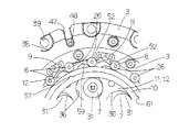
以下,図面を参照して,この発明による減速機の実施例を説明する。この発明による減速機は,移動用装置のタイヤ等の車輪,ロボット,工作機械等の各種装置に取り付けることができる小形で軽量なものであり,摺動部分に潤滑剤を含浸した多孔質成形体から成る潤滑部材9,10を組み込んだことを特徴としている。この減速機は,モータ等の駆動手段に取り付けられた入力軸1からの駆動力を一対のサイクロイド歯車11,12を介して減速して出力軸であるハブ2に伝達するものである。この減速機は,主として,図5に示すように,軸方向に隔置して180°位相を異にする一対の偏心部45,46を備えた入力軸1,偏心部45,46にそれぞれ外接して回転作動する中心孔を備えた一対のサイクロイド歯車11,12,サイクロイド歯車11,12に隣接して入力軸1を回転自在に支持する出力軸を構成するハブ2,ハブ2にサイクロイド歯車11,12を介して隔置して固定され且つ入力軸1を回転自在に支持する出力軸ピンホルダー5,サイクロイド歯車11,12の外周歯形の歯部59を転動する複数の外周歯車ピンとして外周ピン6,外周ピン6を周方向に隔置してそれぞれ保持し且つハブ2と出力軸ピンホルダー5を回転自在に支持する外周ピンホルダー3,及びサイクロイド歯車11,12に形成された複数の挿通孔36をそれぞれ転動し且つハブ2に回転自在に支持された複数の内径出力ピンとしての内周ピン7から構成されている。サイクロイド歯車11,12には,偏心部45,46が挿通する中心孔がそれぞれ形成されている。外周ピンホルダー3には,サイクロイド歯車11,12及び外周ピン6を配設するスペースを形成するため,外周ピンホルダー3に所定の間隔を有して外周ピンホルダー板4が対向配置されて固定されている。外周ピンホルダー板4は,固定ボルト50によって外周ピンホルダー3に固定されている。図5に示すように,入力軸1には,一対の偏心部45,46が軸方向に隣接して設けされており,偏心部45が出力軸ピンホルダー5側に位置し,偏心部46がハブ2側に位置している。また,入力軸1に形成された潤滑剤通路40は,偏心部45,46に隣接状態に形成されている。
Embodiments of a reduction gear according to the present invention will be described below with reference to the drawings. The speed reducer according to the present invention is a small and light-weight porous molded body that can be attached to various devices such as wheels of a moving device such as tires, robots, and machine tools, and has a sliding portion impregnated with a lubricant. It is characterized by incorporating lubricating
この減速機では,図4及び図5に示すように,入力軸1は,軸受21によってハブ2と出力軸ピンホルダー5とに跨がって回転自在に支持されており,ハブ2と出力軸ピンホルダー5が位置する部分は小径に,一対のサイクロイド歯車11,12が位置する部分は大径に形成されている。軸受21は,入力軸1の外周面を転動する複数のローラ23,ハブ2と出力軸ピンホルダー5との中心部に形成された凹部にそれぞれ嵌入した一対の外輪22,及びローラ23を保持する保持器24から構成されている。一対のサイクロイド歯車11,12は,入力軸1の偏心部45,46に偏心部軸受を構成するローラ63を介してそれぞれ外接して回転作動するように構成されている。この減速機は,入力軸1を回転自在に支持する軸受21と偏心部軸受のローラ63との間には,偏心部軸受案内板43がそれぞれ配設されている。偏心部軸受案内板43は,摩擦抵抗を減らすため熱可塑性樹脂であるPEEK(ポリエーテルエーテルケトン樹脂)から作製されている。
In this speed reducer, as shown in FIGS. 4 and 5, the
この減速機において,ハブ2は,外周ピンホルダー3にクロスローラ軸受13を介して支持されている。クロスローラ軸受13は,外周ピンホルダー3に固定された外輪14,ハブ2にねじで固定された内輪15,外輪14と内輪15との間に組み込まれた複数個のローラ16,及びローラ16間に配設されている複数個のセパレータ17から構成されている。この減速機は,ハブ2には複数個の取付け用孔51が形成され,内輪15には複数個の取付けねじ孔44が形成されており,ねじ(図示せず)をハブ2の取付け用孔51に挿通して内輪15の取付けねじ孔44に螺入して,ハブ2に内輪15を固定している。また,外周ピンホルダー3には,複数個の取付け用ねじ孔48が形成されており,外輪14には,外周ピンホルダー3に固定するねじを挿通するための周方向に隔置して複数個の取付け用孔35が形成されている。この減速機は,ねじ(図示せず)を外輪14の取付け用孔35に通して外周ピンホルダー3の取付け用ねじ孔48に螺入して,外周ピンホルダー3に外輪14を固定している。外輪14には,ローラ16とセパレータ17とを外輪14と内輪15との間に組み込むための組込み孔62が形成されており,組込み孔62には蓋18が嵌合されている。蓋18は,ピン19で外輪14に固定されている。また,蓋18には,潤滑剤の供給のため給脂孔20が形成されている。
In this reduction gear, the
また,外周ピン6と内周ピン7は,複数のローラ27,32から成る転がり軸受で構成され,摩擦抵抗によるロスを低減している。実施例では,外周ピン6は16個で構成され,内周ピン7は6個に構成されている。この減速機は,実施例では,サイクロイド歯車11,12の歯数が全周で均等間隔に15個設けられている。外周ピン6及び内周ピン7を構成する転がり軸受の内部には,固形潤滑剤を内蔵させることができる。固形潤滑剤は,潤滑油と超高分子量のポリエチレンパウダーを混合した溶液を転がり軸受の内部に注入して焼き固めて配置することができる。
Further, the outer
この減速機では,外周ピン6は,軸29,該軸29に回転自在に配設された一対の外輪26,及び該外輪26と軸29との間でそれぞれ転動するローラ27から構成されている。外周ピン6の軸29は,その両端が外周ピンホルダー3と外周ピンホルダー板4とにそれぞれ形成された嵌入孔に嵌合して固定され,外周ピン6が固定ピンに形成されている。外周ピン6の軸方向両端には,金属製の側板28がそれぞれ配設されている。外周ピン6の軸29は,サイクロイド歯車1,12の外周歯形の歯部59をそれぞれ転動する一対の外輪26を1本で回転自在にそれぞれ支持している。外周ピンホルダー3に固定された外周ピン6は,その外輪26がサイクロイド歯車11,12の回転に伴ってその歯部59の外周歯形に接して回転し,サイクロイド歯車11,12をガイドしている。
In this speed reducer, the outer
また,内周ピン7は,軸34,該軸34に回転自在に配設された一対の外輪31,及び該外輪31と軸34との間でそれぞれ転動するローラ32から構成されている。内周ピン7の軸34は,その両端が固定ボルト49によってハブ2と出力軸ピンホルダー5とに固定されている。また,この減速機では,サイクロイド歯車11,12には,外輪26,31及びローラ27,32がそれぞれ対向して配設されている。内周ピン7の軸方向両端には,金属製の側板33がそれぞれ配設されている。ハブ2に固定された内周ピン7の軸34は,サイクロイド歯車11,12に形成された挿通孔36の孔周面をそれぞれ転動する一対の外輪31を1本で回転自在にそれぞれ支持している。内周ピン7の外輪31は,サイクロイド歯車11,12に形成された挿通孔36の孔周面に接して回転する。外輪31の外径と挿通孔36の孔径との差は,偏心部45,46の偏心量に相当している。この減速機は,サイクロイド歯車11,12が偏心状に自転するのに従って内周ピン7が回転してハブ2を回転させることになる。
The inner
また,この減速機は,一対の前記サイクロイド歯車11,12の間には,前記サイクロイド歯車11,12を連れ回りすることなく独立的に回転できるように,歯車セパレータリング30が配設されている。歯車セパレータリング30は,アセタール樹脂のPOM(ポリオキシメチレンポリアセタール)から作製されている。更に,サイクロイド歯車11,12がすべり接触する両面の箇所には,摩擦抵抗を減らすため熱可塑性樹脂であるPEEK(ポリエーテルエーテルケトン樹脂)から作製されているスラストワッシャ25が複数箇所にそれぞれ組み込まれている。スラストワッシャ25は,具体的には,一対のサイクロイド歯車11,12の間,サイクロイド歯車12と外周ピンホルダー3との間,サイクロイド歯車11と外周ピンホルダー板4との間,サイクロイド歯車12とハブ2との間,及びサイクロイド歯車11と出力軸ピンホルダー5との間にそれぞれ配設されている。また,一対の外周ピン6は,軸方向に配設され,その間の外輪26間には,金属製のカラー37とカラー37の両側にスラストワッシャ25がそれぞれ配設されている。
The reduction gear is provided with a
この減速機において,外周ピン6のそれぞれの軸29は,外周ピンホルダー3と,出力軸ピンホルダー5の外周に配設されて外周ピンホルダー3に対向配設された外周ピンホルダー板4との間に取り付けられている。それによって,外周ピンホルダー3と外周ピンホルダー板4とは,予め決められた所定の間隔で互いに固定されている。また,内周ピン7のそれぞれの軸34は,ハブ2と,ハブ2に対向配設された出力軸ピンホルダー5との間に取り付けられている。それによって,ハブ2と出力軸ピンホルダー5とは,予め決められた所定の間隔で互いに固定されている。また,この減速機は,出力軸ピンホルダー5がスムーズに回転できるように,外周ピンホルダー板4の内周面と出力軸ピンホルダー5の外周面との間には,サイクロイド歯車11,12が収容されている空間部を密封するためゴム製のシール8が配設されている。即ち,この減速機では,シール8は,2枚のサイクロイド歯車11,12に供給した潤滑剤が入力軸1のモータ側に漏洩しないように,回転しない外周ピンホルダー板4に取り付けられている。シール8のリップ部は,回転する出力軸ピンホルダー5の肩部に接して配設されている。
In this speed reducer, each
この減速機は,特に,外周ピン6と内周ピン7とにそれぞれ接して潤滑する二種類の潤滑部材9,10が組み込まれていることを特徴としている。この減速機では,外周ピン6を潤滑する潤滑部材は,外周ピン6を支持する外周ピンホルダー3の内周面に周方向に所定の間隔(実施例では45度)に隔置して形成された長円形状の凹部60に弾性変形可能にそれぞれ配設された複数個(実施例では8個)のブロック状潤滑部材9である。ブロック状潤滑部材9は,外周ピン6の外輪26を潤滑するものである。具体的には,ブロック状潤滑部材9は,潤滑剤を含浸した多孔質成形体から成り,特に図9に示すように,凹状の内周面53を備えた円弧部64,円弧部64の周方向両側から立ち上がる一対の腕部55,腕部55間の隔置した外側端部に対向形成された貯油部54,及び円弧部64と腕部55と貯油部54とで囲まれた空間部58から形成されている。ブロック状潤滑部材9は,一対の腕部55と隔置した一対の貯油部54で囲まれた空間部58を備えているので,外周ピンホルダー3の凹部60に弾性変形可能に嵌入支持される。ブロック状潤滑部材9は,凹状の内周面53とその周方向の両端面52から成る給脂部を備えている。ブロック状潤滑部材9の内周面53で形成される給脂部は,サイクロイド歯車11,12の歯部59の外周波形に接触して給油し,また,両端面52で形成される給脂部は,隣接する2個の外周ピン6の外輪26にそれぞれ接して給油して潤滑するものである。
This speed reducer is particularly characterized in that two types of
また,この減速機では,内周ピン7を潤滑する潤滑部材は,サイクロイド歯車11,12間に配設された歯車セパレータリング30に支持されて,内周ピン7を潤滑するリング状潤滑部材10であり,リング状潤滑部材10は内周ピン7の外輪31を潤滑するものである。具体的には,リング状潤滑部材10は,潤滑剤を含浸した多孔質成形体から成り,特に図10に示すように,内周ピン7の外輪31にそれぞれ接して潤滑する給脂部として機能する内周面56を備えている。また,リング状潤滑部材10に形成されている給脂部の内周面56は,内周面全域に形成されている。リング状潤滑部材10は,内周ピン7の外輪31の外周面に接触して給油する。リング状潤滑部材10は,サイクロイド歯車11,12間で歯車セパレータリング30の内側に配設されている。リング状潤滑部材10は,実施例では外周面の周方向の4箇所に凸部57が設けられており,また,歯車セパレータリング30の内周面の周方向の4箇所に凹部61が形成されており,リング状潤滑部材10の凸部57と歯車セパレータリング30の凹部61とが係合して,リング状潤滑部材10と歯車セパレータリング30とが周方向に位置決めされている。リング状潤滑部材10は,含浸されている潤滑剤がサイクロイド歯車11,12の端面に給油し,次いで,その潤滑剤は歯車セパレータリング30とサイクロイド歯車11,12とのすべり接触による摩擦抵抗を低減させる機能を有している。また,サイクロイド歯車11,12の端面に給油した潤滑剤は,歯車表面から内周ピン7の外輪31の外周面まで移動して内周ピン7を潤滑することになる。
In this speed reducer, the lubricating member that lubricates the inner
また,この減速機は,外周ピンホルダー3には,周方向に隔置して複数(実施例では6箇所)のTスロット状の切欠き部47が形成されており,切欠き部47には,図示していないが,本減速機に取り付けるモータを固定するボルトの頭部が配設される。切欠き部47は,本減速機をモータに取り付けるため,モータ取付け用のボルトの頭部が配置される。また,外周ピンホルダー3には,周方向に隔置して複数(実施例では12箇所)の座ぐり穴38の取付け用穴39が形成されており,取付け用穴39には外周ピンホルダー3を相手フレームに取り付けるためのボルト(図示せず)が挿通される。また,入力軸1には,入力軸1を駆動するモータの出力軸が連結される。また,ハブ2には,タイヤ等の車輪が取り付けるため取付け用ねじ孔65が形成されている。この減速機では,出力軸であるハブ2には,給脂穴42を設けられており,また,クロスローラ軸受13の外輪14には,給脂孔20を設けられている。クロスローラ軸受13の外輪14に形成した給脂孔20は,クロスローラ軸受13のローラ16とセパレータ17との投入穴を塞ぐ蓋部材18に設けている。ハブ2には,中心部に給脂穴42と給脂穴42に連通する潤滑剤通路41が形成されており,潤滑剤通路41は入力軸1に形成されている潤滑剤通路40に連通している。入力軸1の潤滑剤通路40は,サイクロイド歯車11,12の偏心部軸受のローラ63へと延びており,偏心部軸受のローラ63を潤滑する。この減速機では,補給する潤滑剤は,グリースが使用されている。
Further, in this reduction gear, a plurality of (six in the embodiment) T-
この減速機は,上記のように構成されており,減速機の動力伝達経路は,概して次のとおりである。
この減速機では,移動用装置等の機械装置のスイッチがONされ,モータが回転する。モータの回転は,入力軸1に伝達される。入力軸1には180°位相がずれている一対の偏心部45,46が設けられており,偏心部45,46には,偏心部軸受のローラ63を介してそれぞれ外接して回転作動するサイクロイド歯車11,12が配設されている。入力軸1の回転によって偏心部45,46を介してサイクロイド歯車11,12が偏心して回転する。サイクロイド歯車11,12には,外周面に歯部59及び挿通孔36が形成されている。外周ピン6は,外周ピンホルダー3に軸29が固定されて,外周ピンホルダー3に一種の内歯車を構成しており,その内歯車の外周ピン6の外輪26にサイクロイド歯車11,12の外周面の歯部59が接して回転する。挿通孔36には,ハブ2に軸34が固定された内周ピン7が嵌挿されている。そこで,ハブ2に軸34が固定されている内周ピン7の外輪31はサイクロイド歯車11,12の挿通孔36の孔周面を転動して回転する。即ち,サイクロイド歯車11,12は,入力軸1の偏心部45,46の偏心部軸受を介して遊星歯車として高速で公転しながら同時に低速で自転する。遊星歯車としてのサイクロイド歯車11,12が自転すると,サイクロイド歯車11,12の自転に連れて内周ピン7が回転し,回転する内周ピン7を介して出力軸のハブ2が回転することになる。
実施例では,サイクロイド歯車11,12の歯数が15個であり,リングギヤである内歯車を構成する外周ピン6が16個であるので,減速は次の式で表される。
(15−16)/15=−1/15となり,入力軸1に対してハブ2は,回転方向が逆回転であり,1/15に減速されて回転することになる。
The reduction gear is configured as described above, and the power transmission path of the reduction gear is generally as follows.
In this speed reducer, a switch of a mechanical device such as a moving device is turned on, and the motor rotates. The rotation of the motor is transmitted to the
In the embodiment, since the number of teeth of the cycloid gears 11 and 12 is 15 and the number of the outer
(15−16) / 15 = −1 / 15, and the
この発明による減速機は,移動用装置のタイヤ部分,ロボット,工作機械等の各種装置の動力伝達経路に組み込みこんで使用される小形で軽量な減速機として好ましいものである。 The speed reducer according to the present invention is preferable as a small and light speed reducer used by being incorporated in a power transmission path of various devices such as a tire portion of a moving device, a robot, a machine tool and the like.
1 入力軸
2 ハブ(出力軸)
3 外周ピンホルダー
4 外周ピンホルダー板
5 出力軸ピンホルダー
6 外周ピン
7 内周ピン
9 ブロック状潤滑部材
10 リング状潤滑部材
11,12 サイクロイド歯車
13 クロスローラ軸受
25 スラストワッシャ
26,31 外輪
27,32 ローラ
28,33 側板
29,34 軸
30 歯車セパレータリング
36 挿通孔
45,46 偏心部
47 切欠き部
52 端面(給脂部)
53,56 内周面(給脂部)
59 歯部(外周歯形)
60 凹部
1
3 outer
53, 56 Inner peripheral surface (greasing part)
59 Teeth (outer periphery tooth profile)
60 recess
Claims (12)
前記外周ピンと前記内周ピンとにそれぞれ接して潤滑する複数の潤滑部材が組み込まれており,
前記潤滑部材は,前記外周ピンを支持する前記外周ピンホルダーに形成された凹部に弾性変形可能に嵌入支持されて前記外周ピンの前記外輪に接して潤滑するブロック状潤滑部材であることを特徴とする減速機。 An input shaft having a pair of eccentric portions adjacent to each other in the circumferential direction and having a phase difference of 180 ° in the circumferential direction, a pair of cycloid gears that rotate around each of the eccentric portions, and adjacent to the cycloid gear A hub constituting an output shaft that rotatably supports the input shaft, an output shaft pin holder fixed to the hub via the cycloid gear and rotatably supporting the input shaft, and an outer peripheral tooth profile of the tooth portion of the cycloid gear A plurality of outer peripheral pins that roll, an outer peripheral pin holder that holds the outer peripheral pins spaced apart in the circumferential direction, and rotatably supports the hub and the output shaft pin holder, and the cycloid gear. In the speed reducer comprising inner peripheral pins that respectively roll a plurality of insertion holes and are supported by the hub,
A plurality of lubricating members that are in contact with and lubricate the outer peripheral pin and the inner peripheral pin are incorporated ,
The lubricating member is a block-like lubricating member that is fitted and supported in a recess formed in the outer peripheral pin holder that supports the outer peripheral pin so as to be elastically deformable, and lubricates in contact with the outer ring of the outer peripheral pin. To reducer.
前記外周ピンと前記内周ピンとにそれぞれ接して潤滑する複数の潤滑部材が組み込まれており,
前記潤滑部材は,前記サイクロイド歯車間に配設された歯車セパレータリングの内周面に嵌合支持されて前記内周ピンを潤滑するリング状潤滑部材であることを特徴とする減速機。 An input shaft having a pair of eccentric portions adjacent to each other in the circumferential direction and having a phase difference of 180 ° in the circumferential direction, a pair of cycloid gears that rotate around each of the eccentric portions, and adjacent to the cycloid gear A hub constituting an output shaft that rotatably supports the input shaft, an output shaft pin holder fixed to the hub via the cycloid gear and rotatably supporting the input shaft, and an outer peripheral tooth profile of the tooth portion of the cycloid gear A plurality of outer peripheral pins that roll, an outer peripheral pin holder that holds the outer peripheral pins spaced apart in the circumferential direction, and rotatably supports the hub and the output shaft pin holder, and the cycloid gear. In the speed reducer comprising inner peripheral pins that respectively roll a plurality of insertion holes and are supported by the hub,
A plurality of lubricating members that are in contact with and lubricate the outer peripheral pin and the inner peripheral pin are incorporated,
The lubricating member is reduced the speed you being a ring-shaped lubricant member for lubricating the inner pin to the inner peripheral surface is fitted and supported in disposed the gear separator ring between the cycloid gear.
前記外周ピンと前記内周ピンとにそれぞれ接して潤滑する複数の潤滑部材が組み込まれており,
前記外周ピンホルダーには,周方向に隔置して複数のTスロット状の切欠き部が形成されており,前記切欠き部には前記減速機に取り付けるモータを固定するボルトの頭部が配設されることを特徴とする減速機。 An input shaft having a pair of eccentric portions adjacent to each other in the circumferential direction and having a phase difference of 180 ° in the circumferential direction, a pair of cycloid gears that rotate around each of the eccentric portions, and adjacent to the cycloid gear A hub constituting an output shaft that rotatably supports the input shaft, an output shaft pin holder fixed to the hub via the cycloid gear and rotatably supporting the input shaft, and an outer peripheral tooth profile of the tooth portion of the cycloid gear A plurality of outer peripheral pins that roll, an outer peripheral pin holder that holds the outer peripheral pins spaced apart in the circumferential direction, and rotatably supports the hub and the output shaft pin holder, and the cycloid gear. In the speed reducer comprising inner peripheral pins that respectively roll a plurality of insertion holes and are supported by the hub,
A plurality of lubricating members that are in contact with and lubricate the outer peripheral pin and the inner peripheral pin are incorporated,
The outer peripheral pin holder is formed with a plurality of T-slot-shaped notches spaced apart in the circumferential direction. Bolt heads for fixing a motor to be attached to the speed reducer are arranged in the notches. deceleration machine shall be the feature to be set.
Priority Applications (2)
| Application Number | Priority Date | Filing Date | Title |
|---|---|---|---|
| JP2015172776A JP6613437B2 (en) | 2015-09-02 | 2015-09-02 | Decelerator |
| US15/241,266 US9869383B2 (en) | 2015-09-02 | 2016-08-19 | Reduction gear |
Applications Claiming Priority (1)
| Application Number | Priority Date | Filing Date | Title |
|---|---|---|---|
| JP2015172776A JP6613437B2 (en) | 2015-09-02 | 2015-09-02 | Decelerator |
Publications (3)
| Publication Number | Publication Date |
|---|---|
| JP2017048852A JP2017048852A (en) | 2017-03-09 |
| JP2017048852A5 JP2017048852A5 (en) | 2018-10-11 |
| JP6613437B2 true JP6613437B2 (en) | 2019-12-04 |
Family
ID=58103902
Family Applications (1)
| Application Number | Title | Priority Date | Filing Date |
|---|---|---|---|
| JP2015172776A Active JP6613437B2 (en) | 2015-09-02 | 2015-09-02 | Decelerator |
Country Status (2)
| Country | Link |
|---|---|
| US (1) | US9869383B2 (en) |
| JP (1) | JP6613437B2 (en) |
Families Citing this family (11)
| Publication number | Priority date | Publication date | Assignee | Title |
|---|---|---|---|---|
| DE102016106557A1 (en) | 2016-04-11 | 2017-10-12 | Festool Gmbh | Hand machine tool with a drive motor |
| JP7199147B2 (en) * | 2018-02-07 | 2023-01-05 | 住友重機械工業株式会社 | Eccentric oscillating speed reducer and lubricating method |
| JP6898876B2 (en) * | 2018-02-28 | 2021-07-07 | 住友重機械工業株式会社 | Eccentric swing type speed reducer |
| JP7048049B2 (en) | 2018-03-16 | 2022-04-05 | 日本トムソン株式会社 | Cycloid reducer |
| DE112018007606T5 (en) * | 2018-05-15 | 2021-02-04 | Sri International | Shaft couplings |
| JP7267081B2 (en) * | 2018-07-13 | 2023-05-01 | 株式会社シマノ | Speed reducer for electric reel, method for manufacturing speed reducer for electric reel, and electric reel for fishing |
| CN109404497A (en) * | 2018-11-26 | 2019-03-01 | 珠海格力电器股份有限公司 | A kind of Cycloidal Wheel and speed reducer |
| CN114341524A (en) | 2019-06-13 | 2022-04-12 | 圆波驱动合作伙伴公司 | Circular wave driver |
| WO2021201898A1 (en) | 2020-03-31 | 2021-10-07 | Circular Wave Drive Partners Inc. | Circular wave drive |
| JP2022180821A (en) | 2021-05-25 | 2022-12-07 | 日本トムソン株式会社 | Speed reducer |
| JP2022180820A (en) | 2021-05-25 | 2022-12-07 | 日本トムソン株式会社 | Speed reducer |
Family Cites Families (10)
| Publication number | Priority date | Publication date | Assignee | Title |
|---|---|---|---|---|
| US1770035A (en) * | 1927-09-09 | 1930-07-08 | Heap Walter | Speed-reduction gearing |
| JP2771395B2 (en) * | 1992-07-29 | 1998-07-02 | 住友重機械工業株式会社 | Inner mesh planetary gear structure |
| JP2003021198A (en) * | 2001-07-06 | 2003-01-24 | Sumitomo Heavy Ind Ltd | Transmission using epicyclic gear structure |
| JP4252804B2 (en) | 2003-01-07 | 2009-04-08 | 住友重機械工業株式会社 | Power transmission device |
| JP2006226370A (en) * | 2005-02-16 | 2006-08-31 | Sumitomo Heavy Ind Ltd | Swing inner gearing power transmission device |
| JP2008261445A (en) * | 2007-04-13 | 2008-10-30 | Ntn Corp | In-wheel motor drive device |
| JP2008309264A (en) | 2007-06-15 | 2008-12-25 | Ntn Corp | Cycloid reduction gear and in-wheel motor drive device |
| JP5010484B2 (en) * | 2008-01-08 | 2012-08-29 | Ntn株式会社 | Cycloid reducer and in-wheel motor drive device |
| JP2010249162A (en) * | 2009-04-10 | 2010-11-04 | Ntn Corp | Railway vehicle drive unit |
| JP2015068418A (en) * | 2013-09-30 | 2015-04-13 | Ntn株式会社 | In-wheel motor drive unit |
-
2015
- 2015-09-02 JP JP2015172776A patent/JP6613437B2/en active Active
-
2016
- 2016-08-19 US US15/241,266 patent/US9869383B2/en active Active
Also Published As
| Publication number | Publication date |
|---|---|
| US9869383B2 (en) | 2018-01-16 |
| JP2017048852A (en) | 2017-03-09 |
| US20170059029A1 (en) | 2017-03-02 |
Similar Documents
| Publication | Publication Date | Title |
|---|---|---|
| JP6613437B2 (en) | Decelerator | |
| JP7048049B2 (en) | Cycloid reducer | |
| US9490679B2 (en) | Wheel driving device | |
| JP5792015B2 (en) | In-wheel motor drive device | |
| EP2602509B1 (en) | Speed reduction mechanism, and motor torque transmission device including the same | |
| JP2006258289A (en) | In-wheel motor drive unit | |
| KR101949381B1 (en) | In-wheel motor unit | |
| WO2018147200A1 (en) | Planetary gear device | |
| KR101248306B1 (en) | Acceleration and deceleration device | |
| WO2020056962A1 (en) | Cycloidal gear, reducer and robot | |
| JP4684120B2 (en) | Eccentric rocking speed reducer | |
| CN109139881A (en) | Needle tooth, retarder and robot | |
| US11168764B2 (en) | Planetary gearbox and associated robot joint and robot | |
| JP6890563B2 (en) | Eccentric swing type speed reducer | |
| CN110805660A (en) | Differential cycloidal gear speed change device | |
| WO2022249699A1 (en) | Speed reducer | |
| JP5882966B2 (en) | In-wheel motor drive device | |
| KR20190134189A (en) | Cycloidal Reducers | |
| CN211009751U (en) | Differential cycloidal gear speed change device | |
| WO2018179788A1 (en) | Planetary transmission device and differential device | |
| JP2001065654A (en) | Epicycle roller type motive power transmitting device | |
| CN115698546A (en) | Internal-meshing planetary gear device, wheel device, and vehicle | |
| JPH04210149A (en) | Traction type transmission | |
| JP2019039549A (en) | transmission | |
| JP2018135976A (en) | Differential gear |
Legal Events
| Date | Code | Title | Description |
|---|---|---|---|
| A521 | Request for written amendment filed |
Free format text: JAPANESE INTERMEDIATE CODE: A523 Effective date: 20180516 |
|
| A711 | Notification of change in applicant |
Free format text: JAPANESE INTERMEDIATE CODE: A711 Effective date: 20180516 |
|
| RD02 | Notification of acceptance of power of attorney |
Free format text: JAPANESE INTERMEDIATE CODE: A7422 Effective date: 20180516 |
|
| A521 | Request for written amendment filed |
Free format text: JAPANESE INTERMEDIATE CODE: A821 Effective date: 20180516 |
|
| A521 | Request for written amendment filed |
Free format text: JAPANESE INTERMEDIATE CODE: A523 Effective date: 20180831 |
|
| A621 | Written request for application examination |
Free format text: JAPANESE INTERMEDIATE CODE: A621 Effective date: 20180831 |
|
| A977 | Report on retrieval |
Free format text: JAPANESE INTERMEDIATE CODE: A971007 Effective date: 20190620 |
|
| A131 | Notification of reasons for refusal |
Free format text: JAPANESE INTERMEDIATE CODE: A131 Effective date: 20190709 |
|
| A521 | Request for written amendment filed |
Free format text: JAPANESE INTERMEDIATE CODE: A523 Effective date: 20190805 |
|
| TRDD | Decision of grant or rejection written | ||
| A01 | Written decision to grant a patent or to grant a registration (utility model) |
Free format text: JAPANESE INTERMEDIATE CODE: A01 Effective date: 20190910 |
|
| A61 | First payment of annual fees (during grant procedure) |
Free format text: JAPANESE INTERMEDIATE CODE: A61 Effective date: 20191004 |
|
| R150 | Certificate of patent or registration of utility model |
Ref document number: 6613437 Country of ref document: JP Free format text: JAPANESE INTERMEDIATE CODE: R150 |
|
| R250 | Receipt of annual fees |
Free format text: JAPANESE INTERMEDIATE CODE: R250 |
|
| R250 | Receipt of annual fees |
Free format text: JAPANESE INTERMEDIATE CODE: R250 |