JP6612825B2 - Plant monitoring device and distributed control system - Google Patents
Plant monitoring device and distributed control system Download PDFInfo
- Publication number
- JP6612825B2 JP6612825B2 JP2017181519A JP2017181519A JP6612825B2 JP 6612825 B2 JP6612825 B2 JP 6612825B2 JP 2017181519 A JP2017181519 A JP 2017181519A JP 2017181519 A JP2017181519 A JP 2017181519A JP 6612825 B2 JP6612825 B2 JP 6612825B2
- Authority
- JP
- Japan
- Prior art keywords
- information
- alarm
- database
- urgency
- unit
- Prior art date
- Legal status (The legal status is an assumption and is not a legal conclusion. Google has not performed a legal analysis and makes no representation as to the accuracy of the status listed.)
- Active
Links
Images


Classifications
-
- G—PHYSICS
- G05—CONTROLLING; REGULATING
- G05B—CONTROL OR REGULATING SYSTEMS IN GENERAL; FUNCTIONAL ELEMENTS OF SUCH SYSTEMS; MONITORING OR TESTING ARRANGEMENTS FOR SUCH SYSTEMS OR ELEMENTS
- G05B23/00—Testing or monitoring of control systems or parts thereof
- G05B23/02—Electric testing or monitoring
- G05B23/0205—Electric testing or monitoring by means of a monitoring system capable of detecting and responding to faults
- G05B23/0208—Electric testing or monitoring by means of a monitoring system capable of detecting and responding to faults characterized by the configuration of the monitoring system
-
- G—PHYSICS
- G05—CONTROLLING; REGULATING
- G05B—CONTROL OR REGULATING SYSTEMS IN GENERAL; FUNCTIONAL ELEMENTS OF SUCH SYSTEMS; MONITORING OR TESTING ARRANGEMENTS FOR SUCH SYSTEMS OR ELEMENTS
- G05B19/00—Programme-control systems
- G05B19/02—Programme-control systems electric
- G05B19/04—Programme control other than numerical control, i.e. in sequence controllers or logic controllers
- G05B19/042—Programme control other than numerical control, i.e. in sequence controllers or logic controllers using digital processors
- G05B19/0428—Safety, monitoring
-
- G—PHYSICS
- G05—CONTROLLING; REGULATING
- G05B—CONTROL OR REGULATING SYSTEMS IN GENERAL; FUNCTIONAL ELEMENTS OF SUCH SYSTEMS; MONITORING OR TESTING ARRANGEMENTS FOR SUCH SYSTEMS OR ELEMENTS
- G05B23/00—Testing or monitoring of control systems or parts thereof
- G05B23/02—Electric testing or monitoring
- G05B23/0205—Electric testing or monitoring by means of a monitoring system capable of detecting and responding to faults
- G05B23/0208—Electric testing or monitoring by means of a monitoring system capable of detecting and responding to faults characterized by the configuration of the monitoring system
- G05B23/0216—Human interface functionality, e.g. monitoring system providing help to the user in the selection of tests or in its configuration
-
- G—PHYSICS
- G05—CONTROLLING; REGULATING
- G05B—CONTROL OR REGULATING SYSTEMS IN GENERAL; FUNCTIONAL ELEMENTS OF SUCH SYSTEMS; MONITORING OR TESTING ARRANGEMENTS FOR SUCH SYSTEMS OR ELEMENTS
- G05B23/00—Testing or monitoring of control systems or parts thereof
- G05B23/02—Electric testing or monitoring
- G05B23/0205—Electric testing or monitoring by means of a monitoring system capable of detecting and responding to faults
- G05B23/0259—Electric testing or monitoring by means of a monitoring system capable of detecting and responding to faults characterized by the response to fault detection
- G05B23/0267—Fault communication, e.g. human machine interface [HMI]
- G05B23/0272—Presentation of monitored results, e.g. selection of status reports to be displayed; Filtering information to the user
-
- G—PHYSICS
- G06—COMPUTING; CALCULATING OR COUNTING
- G06F—ELECTRIC DIGITAL DATA PROCESSING
- G06F16/00—Information retrieval; Database structures therefor; File system structures therefor
- G06F16/90—Details of database functions independent of the retrieved data types
- G06F16/901—Indexing; Data structures therefor; Storage structures
-
- G—PHYSICS
- G08—SIGNALLING
- G08B—SIGNALLING OR CALLING SYSTEMS; ORDER TELEGRAPHS; ALARM SYSTEMS
- G08B21/00—Alarms responsive to a single specified undesired or abnormal condition and not otherwise provided for
- G08B21/18—Status alarms
Landscapes
- Engineering & Computer Science (AREA)
- Physics & Mathematics (AREA)
- General Physics & Mathematics (AREA)
- Automation & Control Theory (AREA)
- Human Computer Interaction (AREA)
- Databases & Information Systems (AREA)
- Theoretical Computer Science (AREA)
- Emergency Management (AREA)
- Software Systems (AREA)
- Data Mining & Analysis (AREA)
- General Engineering & Computer Science (AREA)
- Business, Economics & Management (AREA)
- Testing And Monitoring For Control Systems (AREA)
Description
本発明の実施形態は、プラント監視装置および分散制御システムに関する。 Embodiments described herein relate generally to a plant monitoring apparatus and a distributed control system.
従来から、産業プラント(以下、単に「プラント」という)を制御するDCS(分散制御システム、Distributed Control System)等において、I/O(Input/Output)機器等を制御するためにコントローラが用いられている。また、このようなコントローラにおける処理の実行状況等をオペレータが監視するために、HMI(Human Machine Interface)等のプラント監視装置が用いられている。 Conventionally, in a DCS (Distributed Control System) that controls an industrial plant (hereinafter simply referred to as “plant”), a controller has been used to control I / O (Input / Output) devices and the like. Yes. In addition, a plant monitoring device such as an HMI (Human Machine Interface) is used for an operator to monitor the execution status of processing in such a controller.
例えば、プラント内で異常が発生した場合等に、プラント監視装置は、コントローラから当該異常の発生を示すアラームの情報を取得し、ディスプレイ等に表示することにより、オペレータにアラームを認識させる。一般に、プラント監視装置は各オペレータに1台ずつ割り当てられ、各オペレータは、ディスプレイ等に表示されたアラームの内容に応じて復旧等の対応をしていた。 For example, when an abnormality occurs in the plant, the plant monitoring apparatus acquires alarm information indicating the occurrence of the abnormality from the controller and displays it on a display or the like, thereby causing the operator to recognize the alarm. In general, one plant monitoring device is assigned to each operator, and each operator takes measures such as recovery according to the content of an alarm displayed on a display or the like.
しかしながら、従来技術においては、各オペレータが個々のアラームに対して下した判断の内容が、他のオペレータに対して逐次共有されていなかった。このため、大量のアラームが発生した場合に、複数のオペレータが協調して作業にあたることが困難な場合があった。 However, in the prior art, the contents of judgments made by each operator for individual alarms are not sequentially shared with other operators. For this reason, when a large number of alarms occur, it may be difficult for a plurality of operators to work together.
実施形態のプラント監視装置は、記憶部と、登録部と、表示制御部とを備える。記憶部は、アラームを特定する識別情報であるアラーム情報に対して複数の緊急度情報を登録可能なアラームデータベースを有する。登録部は、アラーム情報に対する緊急度情報が入力された場合に、緊急度情報をアラーム情報と対応付けてアラームデータベースに登録する。表示制御部は、アラームデータベースに登録されたアラーム情報と、当該アラーム情報に対する緊急度情報に基づいたアラームの緊急度および複数のオペレータによる協調対応の要否を表した詳細情報とを、緊急度情報に応じた表示態様で表示部に表示する。 The plant monitoring apparatus according to the embodiment includes a storage unit, a registration unit, and a display control unit . The storage unit has an alarm database in which a plurality of pieces of urgency information can be registered for alarm information that is identification information for identifying an alarm. Registration unit, when the emergency degree information for the alarm information is input, and registers the alarm database urgency information in association with alarm information. The display control unit displays the alarm information registered in the alarm database, the urgency level of the alarm based on the urgency level information for the alarm information, and detailed information indicating the necessity of cooperative correspondence by a plurality of operators. Is displayed on the display unit in a display mode according to the above.
(実施形態1)
図1は、本実施形態にかかる分散制御システム100の全体構成の一例を示す図である。図1に示すように、分散制御システム100は、コントローラ2a〜2nと、HMI(Human Machine Interface)1a〜1nと、エンジニアリングツール用のPC3と、を含む。コントローラ2a〜2nと、HMI1a〜1nと、エンジニアリングツール用のPC3とは、LAN5を介して通信可能に接続されている。
(Embodiment 1)
FIG. 1 is a diagram illustrating an example of the overall configuration of a
コントローラ2a〜2nは、分散制御システム(DCS)100用のコントローラである。より詳細には、コントローラ2a〜2nは、プラントのセンサ等からの各種入力情報を演算し、制御対象であるバルブなどの機器に出力情報を与えることにより、プラントを制御する。一般に、1つの分散制御システム100には複数のコントローラ2a〜2nが含まれる。本実施形態においては、コントローラ2a〜2nの台数は特に限定されるものではない。以下、コントローラ2a〜2nを特に区別しない場合は、単にコントローラ2という。
The
コントローラ2は、CPU(Central Processing Unit)201と、RAM(Random Access Memory)202と、ツールインタフェース203と、FROM(Flash Read Only Memory)204と、I/Oインタフェース205と、バス206とを備えるコンピュータとして構成される。図1に示すコントローラ2のハードウェア構成は一例であり、これに限定されるものではない。
The
ツールインタフェース203は、他のコントローラ2や、HMI1a〜1n、エンジニアリングツール用のPC3との間で情報の送受信を行うためのインタフェースである。
The
I/Oインタフェース205は、制御対象の機器や、各種のセンサ等との間で情報の送受信を行うためのインタフェースである。
The I /
また、HMI1a〜1nは、コントローラ2で実行される処理の状況等を、オペレータが監視するために用いられる装置である。一般に、1つの分散制御システム100には複数のHMI1a〜1nが含まれる。本実施形態においては、オペレータ1人につき、1台のHMI1a〜1nが割当てられるものとするが、HMI1の台数はこれに限定されるものではない。以下、HMI1a〜1nを特に区別しない場合は、単にHMI1という。各HMI1は、各オペレータが自装置に入力した情報を他のHMI1へ送信し、また、各オペレータが他のHMI1に入力した情報を受信することにより、各HMI1間で情報の共有(同期)をする。オペレータがHMI1に入力する情報の詳細については、後述する。HMI1は、本実施形態におけるプラント監視装置の一例である。
The
HMI1は、CPU101と、RAM102と、HDD103と、ROM(Read Only Memory)104と、ディスプレイ(表示部)105と、マウスやキーボード等の入力装置106と、通信インタフェース107と、バス108とを備える。HMI1は、通常のハードウェア構成を備えるPC(Personal Computer)等であれば良い。
The
通信インタフェース107は、他のHMI1や、コントローラ2、エンジニアリングツール用のPC3との間で情報の送受信を行うためのインタフェースである。
The
エンジニアリングツール用のPC3(以下、PC3という)は、エンジニアリングツール31を備えるコンピュータである。PC3は、HMI1と同様に、通常のコンピュータのハードウェア構成を備える。
The engineering tool PC 3 (hereinafter referred to as PC 3) is a computer including the
エンジニアリングツール31は、コントローラ2で実行される制御プログラムやタスクの生成や、制御プログラムで使用されるパラメータの値の設定をすることができるソフトウェアである。エンジニアリングツール31は、PC3のユーザであるエンジニアによって操作され、プログラム等を生成する。エンジニアリングツール31で生成されたプログラム等がLAN5を介してコントローラ2にダウンロードされることにより、コントローラ2がプラントを制御するための処理を実行することができる。コントローラ2で実行される制御プログラム等については、後述する。
The
図2は、本実施形態にかかるHMI1およびコントローラ2の機能的構成の一例を示す図である。
FIG. 2 is a diagram illustrating an example of a functional configuration of the
コントローラ2は、記憶部25と、送信部21とを備える。
The
記憶部25は、タグデータベース(DB)251と、タスク252とを記憶する。また、記憶部25は、例えば、FROM204により構成される。
The
タスク252は、複数の制御プログラムが機能ごとにまとめられた、コントローラ2で実行される処理の実行単位である。一般に、記憶部25は、複数のタスク252を記憶する。また、1つのタスク252は、1または複数のPOU(Program Organization Unit)を含む。POUは、機能毎にモジュール化して作成された制御プログラムである。タスク252およびタスク252に含まれるPOUは、エンジニアリングツール31で生成され、コントローラ2にダウンロードされる。タスク252とPOUの詳細については後述する。
The
また、タグデータベース251には、コントローラ2で実行される処理で使用されるタグデータが保存される。タグデータは、POU単位で対応付けられた複数のパラメータの値を含むパラメータ群である。より詳細には、タグデータは、対象とする処理(POU)を示すタグ名称と、当該タグ名称に対応付けられるパラメータの値とを含む。例えば、タグ名称“Ind0001”のタグデータ29は、パラメータの値として、当該処理で発生したアラームの種類を示す“PH”を含む。“PH”は、監視対象のセンサ等の現在値(PV,Process Value)が上限値を超えたことを示すアラームである。なお、タグデータ29に含まれるパラメータ値は、アラームの種類に限定されるものではない。例えば、タグデータ29は、POU内のファンクションブロックで使用されるパラメータ値や、アラームの発生を判断する閾値、発生したアラームの重要度(グレード)を示すパラメータ値等をさらに含むものであっても良い。また、センサ等の現在値が正常範囲に戻る等により、アラームが回復(終了)した場合は、タグデータ29から、アラームの種類を示す情報が削除される。
The
送信部21は、タグデータベース251に保存されたタグデータのうち、アラームの種類が設定されたタグデータを読み出し、当該タグデータのタグ名称と、当該タグ名称に対応付けられたアラームの種類とを、HMI1に送信する。本実施形態においては、タグデータに含まれるパラメータのうち、タグ名称と、当該タグ名称に対応付けられたアラームの種類を示す情報とを、アラームを特定する識別情報であるアラーム情報とする。また、送信部21は、アラームが回復した場合に、回復したアラームを特定するアラーム回復情報を、HMI1に送信する。
The
また、HMI1aは、表示制御部11aと、受付部12aと、第1の受信部13aと、第2の受信部14aと、登録部15aと、送信部16aと、記憶部17aとを備える。
The
また、HMI1nも、HMI1aと同様に、表示制御部11nと、受付部12nと、第1の受信部13nと、第2の受信部14nと、登録部15nと、送信部16nと、記憶部17nと、を備える。各HMI1は同様の機能を備えるため、以下、いずれのHMI1の機能であるかを特に限定しない場合は、単に表示制御部11、受付部12、第1の受信部13、第2の受信部14、登録部15、送信部16、記憶部17という。
Similarly to the
記憶部17は、アラームデータベース(DB)171(171a,171n)と、判断データベース(DB)172(172a,172n)と、を有する。記憶部17は、例えばHDD103で構成される。
The storage unit 17 includes an alarm database (DB) 171 (171a, 171n) and a determination database (DB) 172 (172a, 172n). The storage unit 17 is configured by, for example, the
アラームデータベース171は、アラーム情報と、自装置で入力された当該アラーム情報に対するオペレータが判断した内容を表す第1の判断情報と、他のHMI1で入力された当該アラーム情報に対する他のオペレータが判断した内容を表す第2の判断情報と、を対応付けたデータベースである。
The alarm database 171 includes alarm information, first determination information representing contents determined by the operator for the alarm information input by the own device, and other operators determined for the alarm information input by another
第1の判断情報および第2の判断情報は、各オペレータが判断した内容を特定可能な識別情報であり、本実施形態では判断No.(数字)とする。換言すれば、アラームデータベース171はアラーム情報と、当該アラーム情報に対する各オペレータごとの判断No.とが登録されたデータベースである。また、第1の判断情報および第2の判断情報は、数字に限らず、コードなどの文字列や、文章等であっても良い。 The first determination information and the second determination information are identification information that can specify the content determined by each operator. (Number). In other words, the alarm database 171 includes alarm information and a judgment number for each operator for the alarm information. Is a registered database. The first determination information and the second determination information are not limited to numbers, and may be a character string such as a code, a sentence, or the like.
また、本実施形態におけるアラームデータベース171に登録されるオペレータごとの判断は、各アラームに対する最終的な判断だけではなく、各オペレータがアラームを確認した際にそれぞれ下した一次判断を含む。また、状況の変化等により、アラームデータベース171に登録される判断No.はオペレータによって更新される場合もある。アラームデータベース171の詳細については、後述する。 In addition, the determination for each operator registered in the alarm database 171 in the present embodiment includes not only a final determination for each alarm but also a primary determination made when each operator confirms the alarm. Further, the judgment No. registered in the alarm database 171 due to a change in the situation or the like. May be updated by the operator. Details of the alarm database 171 will be described later.
判断データベース172は、第1の判断情報または第2の判断情報を示す共通判断情報と、共通判断情報の詳細を表す詳細情報と、表示態様と、を対応付けたデータベースである。本実施形態における共通判断情報は、第1の判断情報および第2の判断情報と同様に、判断No.である。換言すれば、判断データベース172に登録された情報は、アラームデータベース171に登録された判断No.に紐付くマスタデータである。 The determination database 172 is a database in which common determination information indicating first determination information or second determination information, detailed information indicating details of the common determination information, and a display mode are associated with each other. The common determination information in the present embodiment is the same as the first determination information and the second determination information. It is. In other words, the information registered in the determination database 172 includes the determination No. registered in the alarm database 171. This is the master data associated with.
詳細情報は、アラーム情報に対してオペレータが判断した内容や、アラームに対する対応状況等を、他のオペレータにも理解可能な程度に詳細に表した情報である。 The detailed information is information that shows details determined by the operator with respect to the alarm information, the response status to the alarm, and the like in a detail that can be understood by other operators.
表示態様は、第1の判断情報または第2の判断情報がディスプレイ105に表示される際の表示態様を示す情報である。判断データベース172の詳細については、後述する。
The display mode is information indicating a display mode when the first determination information or the second determination information is displayed on the
また、本実施形態においては、判断データベース172のデータは予め登録されており、オペレータは、判断データベース172に登録された判断No.の中から自己の判断に合う判断No.を選択して、各アラーム情報に対して設定(入力)する。オペレータによる判断No.の入力については、後述する。 In this embodiment, the data of the determination database 172 is registered in advance, and the operator can determine the determination number registered in the determination database 172. No. that matches your judgment Select and set (input) each alarm information. Judgment No. by operator Will be described later.
表示制御部11は、アラームデータベース171に登録されたアラーム情報と、当該アラーム情報に対応付けられたオペレータごとの判断No.に対応付けられた、判断データベース172に登録された詳細情報と、を、判断No.に対応付けられた表示態様に基づいてディスプレイ105に表示する。表示制御部11が、判断No.に対応付けられた詳細情報を表示することで、判断No.を直接表示するよりも、各オペレータの判断の内容が他のオペレータにも把握しやすくなる。
The
また、表示制御部11は、アラーム情報を表示する画面と、各アラーム情報に対応付けられた判断No.に紐付く詳細情報を表示する画面とを、別個の画面として表示しても良いし、同一の画面上にアラーム情報および詳細情報を表示しても良い。
The
また、表示制御部11は、各アラーム情報に対する判断No.の入力画面をディスプレイ105に表示する。また、この際、表示制御部11は、判断データベース172に登録された判断No.と詳細情報とを、オペレータが選択することができるように、ディスプレイ105に表示する。
The
また、本実施形態においては、表示制御部11による表示のタイミングは、アラームデータベース171が更新された場合とする。表示のタイミングはこれに限定されるものではない。例えば、表示制御部11は、所定の時間ごとにアラームデータベース171および判断データベース172を読み込んで、アラーム情報および詳細情報を表示しても良い。
In the present embodiment, the display timing by the
受付部12は、アラーム情報に対する判断No.の入力を受け付ける。より詳細には、受付部12は、ディスプレイ105に表示された各アラーム情報に対する判断No.の入力画面にオペレータが入力した判断No.を、受け付ける。
The accepting
第1の受信部13は、コントローラ2から送信されたアラーム情報およびアラーム回復情報を受信する。第1の受信部13は、受信したアラーム情報を、アラームデータベース171に登録(追加)する。また、第1の受信部13は、受信したアラーム情報をアラームデータベース171に登録する前に、当該アラーム情報でアラームデータベース171を検索し、当該アラーム情報がまだ登録されていない場合に、アラームデータベース171に登録しても良い。登録前に重複の確認をすることにより、同じデータを不要に上書きする処理を行うことを防ぐことができる。
The first receiving unit 13 receives alarm information and alarm recovery information transmitted from the
また、第1の受信部13は、アラーム回復情報を受信した場合、当該アラーム回復情報に対応するアラーム情報および当該アラーム情報に対応付けられた判断No.をアラームデータベース171から削除する。 When receiving the alarm recovery information, the first receiving unit 13 receives the alarm information corresponding to the alarm recovery information and the determination No. associated with the alarm information. Is deleted from the alarm database 171.
第2の受信部14は、分散制御システム100に含まれる他のHMI1(例えばHMI1n)から、アラーム情報と、当該アラーム情報に対応付けられた、他のHMI1で入力された他のオペレータの判断No.と、を受信する。
The second receiving unit 14 receives the alarm information from another HMI 1 (for example,
登録部15は、アラーム情報に対する第1の判断情報が入力された場合、第1の判断情報を、アラーム情報と対応付けてアラームデータベース171に登録する。また、登録部15は、アラーム情報に対する第2の判断情報を受信した場合、第2の判断情報を、アラーム情報と対応付けてアラームデータベース171に登録する。より詳細には、登録部15は、受付部12が自装置のオペレータから何れかのアラーム情報に対する判断No.の入力を受け付けた場合に、当該判断No.を、アラーム情報と、オペレータの識別情報と対応付けてアラームデータベース171に登録する。また、登録部15は、第2の受信部14が他のHMI1から、アラーム情報と当該アラーム情報に対応付けられた判断No.とを受信した場合に、当該判断No.を、アラーム情報と他のHMI1のユーザであるオペレータの識別情報と対応付けてアラームデータベース171に登録する。
When the first determination information for the alarm information is input, the registration unit 15 registers the first determination information in the alarm database 171 in association with the alarm information. In addition, when receiving the second determination information for the alarm information, the registration unit 15 registers the second determination information in the alarm database 171 in association with the alarm information. More specifically, the registration unit 15 causes the
送信部16は、アラームデータベース171に登録されたデータのうち、オペレータから自装置に入力された判断No.と、当該判断No.が対応付けられたアラーム情報とを、他のHMI1へ送信する。例えば、HMI1aの送信部16aは、オペレータAが入力した判断No.と、当該判断No.に対応付けられたアラーム情報とを、HMI1nに送信する。
Of the data registered in the alarm database 171, the transmitter 16 receives the judgment No. input from the operator to the own device. And the judgment No. Is transmitted to the
また、本実施形態においては、送信部16は、入力された判断No.がアラームデータベース171に登録された場合に他のHMI1への送信を実行するが、送信部16による送信タイミングはこれに限定されるものではない。例えば、送信部16は、所定の時間ごとに他のHMI1への送信を実行しても良い。また、所定の時間ごとに送信を実行する場合、送信部16は、前回の送信以降にアラームデータベース171に登録または更新された自装置のオペレータの判断No.および当該判断No.が対応付けられたアラーム情報を送信対象とする。あるいは、送信部16は、アラームデータベース171に登録されたデータのうち、自装置を使用するオペレータに対応付けられた全データを送信対象としても良い。また、送信部16は、他のHMI1から要求された判断No.および当該判断No.が対応付けられたアラーム情報を送信する構成を採用しても良い。
In the present embodiment, the transmission unit 16 receives the input determination number. Is registered in the alarm database 171, transmission to another
次に、上述のコントローラ2で実行されるタスク252およびPOUについて詳細を説明する。
図3は、本実施形態にかかるコントローラ2で実行されるタスク252の構成の一例を説明する図である。図3では、一例として、最大許容実行時間の長いメインスキャンタスク(MSタスク)であるタスク252aと、最大許容実行時間の短いハイスピードスキャンタスク(HSタスク)であるタスク252bとを挙げる。
Next, the
FIG. 3 is a diagram for explaining an example of the configuration of the
タスク252aは、最大許容実行時間の長いメインスキャンタスク(MSタスク)である。タスク252aに含まれる、機能毎にモジュール化して作成された制御プログラムであるPOU1〜3は、実行順に沿ってタスクエントリ1〜3に設定される。例えば、POU1は、ファンクションブロック20a〜20e(以下、ファンクションブロック20という)で構成される1つの制御プログラムである。
The
また、POU1〜3内の各ファンクションブロック20の処理で用いられるパラメータの値は、タグデータベース251に格納されたタグデータに含まれる。
The parameter values used in the processing of the function blocks 20 in the
また、各タスク252は、スキャン周期にしたがって実行される。例えば、タスク252aのスキャン周期は、“1000ms”と設定されているため、タスク252aは、POU1〜3を1000msごとに、実行する。一般に、次のスキャン周期が開始される前にPOU1〜3の処理が終了している必要があるため、スキャン周期はタスク252aの全体の最大許容実行時間となる。
Each
次に、上述のアラームデータベース171の詳細を説明する。
図4は、本実施形態にかかるアラームデータベース171aのデータ構成の一例を示す図である。図4に示すように、アラームデータベース171aでは、アラーム情報と、当該アラーム情報に対するHMI1aで入力されたオペレータAの判断No.と、当該アラーム情報に対する他のHMI1、例えばHMI1nで入力されたオペレータNの判断No.とが対応付けられている。アラームデータベース171aにおけるオペレータAの判断No.は、本実施形態における第1の判断情報の一例であり、オペレータNの判断No.は、本実施形態における第2の判断情報の一例である。
Next, details of the alarm database 171 will be described.
FIG. 4 is a diagram illustrating an example of a data configuration of the
本実施形態のアラームデータベース171においては、各オペレータごとに判断No.の項目(カラム、列)を設けているが、アラームデータベース171の構成はこれに限定されるものではない。例えば、アラームデータベース171は、各オペレータを識別する識別情報の項目を設けても良い。 In the alarm database 171 of the present embodiment, the judgment No. is determined for each operator. However, the configuration of the alarm database 171 is not limited to this. For example, the alarm database 171 may include an item of identification information for identifying each operator.
また、HMI1aとHMI1nとの間で各オペレータの判断No.と、当該判断No.に対応付けられたアラーム情報とが送受信された後は、アラームデータベース171aに登録されたデータと、アラームデータベース171bとに登録されたデータとは同一となる。
In addition, each operator's decision No. between the
次に、上述の判断データベース172の詳細を説明する。
図5は、本実施形態にかかる判断データベース172aのデータ構成の一例を示す図である。判断データベース172aでは、判断No.と、詳細情報と、表示色とが対応付けられている。
Next, details of the above-described determination database 172 will be described.
FIG. 5 is a diagram illustrating an example of a data configuration of the
詳細情報は、アラーム情報に対してオペレータが判断した内容や、アラームに対する対応状況等を、他のオペレータにも理解可能な程度に詳細に表したものであれば良く、例えば「対応中、支援不要」等の短い文章である。 The detailed information may be any information that expresses the details of the alarm information that the operator has determined, the response status to the alarm, etc. in a detail that can be understood by other operators. "Is a short sentence.
また、表示色は、表示態様の一例であり、ディスプレイ105に表示する際に用いられるアイコンや、文字色等を示す。表示色は、緊急度や、重要性に応じて設定される。表示態様は表示色に限定されるものではなく、色の濃淡や、フリッカ(点滅)の間隔等の他の情報でも良い。
The display color is an example of a display mode, and indicates an icon used when displaying on the
ここで、判断データベース172の各行に相当する、判断No.と、詳細情報と、表示色とを対応付けたデータを、判断データという。また、本実施形態において、各HMI1における判断データベース172には同じデータが予め登録されているため、判断データベース172nにも、判断データベース172aと同じ判断データが登録されている。
Here, a judgment No. corresponding to each row of the judgment database 172. The data in which the detailed information is associated with the display color is referred to as determination data. In the present embodiment, since the same data is registered in advance in the determination database 172 in each
本実施形態における判断データベース172の構成および登録された詳細情報等の内容は一例であり、これらに限定されるものではない。 The configuration of the determination database 172 and the contents of the registered detailed information and the like in the present embodiment are examples, and are not limited to these.
次に、以上のように構成された本実施形態のHMI1におけるプラント監視処理について説明する。
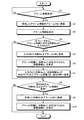
図6は、本実施形態にかかるHMI1で実行されるプラント監視処理の流れの一例を示すフローチャートである。
Next, the plant monitoring process in HMI1 of this embodiment comprised as mentioned above is demonstrated.
FIG. 6 is a flowchart illustrating an example of a flow of plant monitoring processing executed by the
HMI1の第1の受信部13は、コントローラ2から送信されたアラーム情報を受信した場合(S1“Yes”)、受信したアラーム情報をアラームデータベース171に登録する(S2)。また、第1の受信部13は、アラーム情報を受信しない場合(S1“No”)、S1の処理を繰り返して待機する。
When receiving the alarm information transmitted from the controller 2 (S1 “Yes”), the first receiving unit 13 of the
表示制御部11は、アラームデータベース171に登録されたアラーム情報をディスプレイ105に表示する(S3)。
The
オペレータから、表示されたアラーム情報に対する判断No.の入力を受付部12が受け付けた場合(S4“Yes”)、登録部15は、入力された判断No.を、アラーム情報に対応付けてアラームデータベース171に登録する(S5)。 The operator determines the judgment No. for the displayed alarm information. Is received by the receiving unit 12 (S4 “Yes”), the registration unit 15 determines that the input determination No. Are registered in the alarm database 171 in association with the alarm information (S5).
表示制御部11は、アラームデータベース171に登録されたアラーム情報と判断No.とを読み出す。また、表示制御部11は、当該判断No.に対応付けられた詳細情報と表示色とを判断データベース172から、読み出す。そして、表示制御部11は、読み出したアラーム情報と、当該アラーム情報に対応付けられた判断No.に対応付けられた詳細情報とを、当該アラーム情報に対応付けられた判断No.に対応付けられた表示色の文字色(あるいは、登録された表示色のアイコン)でディスプレイ105に表示する(S6)。この時点では、自装置のオペレータによって入力された判断No.に対応付けられた詳細情報が、表示される。
The
そして、送信部16は、アラームデータベース171に登録されたデータのうち、オペレータから入力された判断No.と、当該判断No.が対応付けられたアラーム情報とを対応付けて、他のHMI1へ送信する(S7)。 Then, the transmission unit 16 determines the judgment No. input from the operator among the data registered in the alarm database 171. And the judgment No. Are associated with the alarm information and transmitted to the other HMI 1 (S7).
そして、第2の受信部14が、他のHMI1から、他のHMI1で入力された他のオペレータの判断No.および当該判断No.が対応付けられたアラーム情報を受信した場合(S8“Yes”)、登録部15は、受信した他のオペレータの判断No.を、受信したアラーム情報に対応付けて、アラームデータベース171に登録する(S9)。
Then, the second receiving unit 14 receives the judgment No. of another operator input from the
そして、表示制御部11は、アラーム情報と、当該アラーム情報に対応付けられた判断No.に対応付けられた詳細情報とを、当該アラーム情報に対応付けられた判断No.に対応付けられた表示色の文字色で表示する(S10)。ここでは、自装置のオペレータによって入力された判断No.に対応付けられた詳細情報に加えて、他のHMI1で入力された他のオペレータの判断No.に対応付けられた詳細情報が表示される。
Then, the
また、アラーム情報に対する判断No.の入力を受付部12が受け付けない場合(S4“No”)、S5〜S7の処理は実行されず、S8の処理へ進む。また、第2の受信部14が、他のHMI1から判断No.およびアラーム情報を受信しない場合(S8“No”)、S9,S10の処理は実行されず、このフローチャートの処理は終了する。
In addition, the judgment No. for alarm information. Is not received by the receiving unit 12 (S4 “No”), the processing of S5 to S7 is not executed, and the process proceeds to S8. In addition, the second receiving unit 14 receives a determination No. from another
なお、上述のS3の時点で既に、アラームデータベース171内のいずれかのアラーム情報に対して判断No.が登録されている場合は、表示制御部11は、アラーム情報と、詳細情報とを表示しても良い。
It should be noted that at the time of the above-described S3, the judgment No. Is registered, the
従来技術においては、例えば、プラントにおいて大量のアラームが発生した場合に、複数のオペレータで分担をして対応をしようとしても、他のオペレータが各アラームに対してどのような判断を下したか、あるいはどのような対応状況であるのかを逐次共有することは困難であった。また、オペレータ間の口頭連絡等でアラームに対して各オペレータが判断した内容の情報収集をすることができたとしても、大量のアラームが発生している状況においては、頻繁にこのようなコミュニケーションをとることが困難である場合があり、他のオペレータの最新の判断内容を把握することが困難であった。このため、従来技術においては、複数のオペレータが協調して作業にあたることが困難な場合があった。 In the prior art, for example, when a large number of alarms occur in a plant, what kind of judgment other operators have made for each alarm even if they try to deal with a plurality of operators? Alternatively, it was difficult to sequentially share what kind of response situation. In addition, even if it is possible to collect information on the contents of each operator's judgment for alarms through oral communication between operators, such communication is frequently performed in situations where a large number of alarms are occurring. It may be difficult to take, and it is difficult to grasp the latest judgment contents of other operators. For this reason, in the prior art, it may be difficult for a plurality of operators to work together.
一方、本実施形態のHMI1によれば、アラーム情報と、自装置で入力された当該アラーム情報に対する判断No.と、他のHMI1で入力された当該アラーム情報に対する判断No.とがアラームデータベース171に登録されているため、HMI1を使用するオペレータに対して、他のオペレータが判断した内容を通知することが可能である。このため、本実施形態のHMI1によれば、口頭連絡等での情報共有をせずとも、複数のオペレータが協調して作業にあたることが容易となる。
On the other hand, according to the
また、本実施形態のHMI1によれば、コントローラ2ではなくHMI1がアラームデータベース171を有するため、コントローラ2の構成を変更せずに、HMI1側で各アラームに対する各オペレータごとの判断内容を共有することができる。
Further, according to the
また、本実施形態のHMI1によれば、判断データベース172に登録された表示態様に応じてディスプレイ105への表示を行うため、各オペレータは、他のオペレータが各アラームに対して判断した内容の緊急度等を、画面上でより容易に認識することができる。また、判断データベース172に記憶された詳細情報をディスプレイ105に表示するため、各オペレータは、他のオペレータが判断した内容を詳細に把握することができる。
Further, according to the
なお、本実施形態においては1台のHMI1を1人のオペレータが使用するものとしたが、1台のHMI1を複数人のオペレータが使用しても良い。このような場合、HMI1は、例えば、オペレータを識別するユーザID等の入力を、判断No.の入力の際に受け付けることにより、各オペレータが入力した判断No.を特定しても良い。
In this embodiment, one
また、本実施形態では、アラームデータベース171と判断データベース172との2つのデータベースが用いられる構成を採用したが、1つのデータベースにアラームデータベース171と判断データベース172の内容が含まれる構成を採用しても良い。また、判断No.のかわりに、詳細情報が、第1の判断情報および第2の判断情報として、アラームデータベース171に登録される構成を採用しても良い。 In the present embodiment, a configuration in which two databases of the alarm database 171 and the determination database 172 are used is employed. However, a configuration in which the contents of the alarm database 171 and the determination database 172 are included in one database may be employed. good. In addition, the judgment No. Instead, a configuration in which the detailed information is registered in the alarm database 171 as the first determination information and the second determination information may be adopted.
また、本実施形態では、第1の受信部13が、受信したアラーム情報をアラームデータベース171に登録するとしたが、第1の受信部13が受信したアラーム情報を、登録部15がアラームデータベース171に登録する構成を採用しても良い。 In the present embodiment, the first receiving unit 13 registers the received alarm information in the alarm database 171. However, the registration unit 15 stores the alarm information received by the first receiving unit 13 in the alarm database 171. You may employ | adopt the structure to register.
また、本実施形態では、アラーム情報は、アラームが発生した処理に対応するタグ名称と、当該タグ名称に対応付けられたアラームの種類を示す情報とであるとしたが、アラーム情報は、これに限定されるものではない。例えば、アラーム情報は、さらに、アラームの重要度等の情報を含むものでも良い。 In the present embodiment, the alarm information is a tag name corresponding to the process in which the alarm has occurred and information indicating the type of alarm associated with the tag name. It is not limited. For example, the alarm information may further include information such as the importance of the alarm.
(実施形態2)
実施形態1では、オペレータは、判断データベースに予め登録された詳細情報や表示色から、自己の判断に合うものを選択して、各アラーム情報に対して設定していた。本実施形態においては、オペレータによる判断データベースへの詳細情報や表示色の登録を許可することにより、より状況に適合した判断内容の共有を可能にする。
(Embodiment 2)
In the first embodiment, the operator selects from the detailed information and display color registered in advance in the determination database, the one that matches his / her own determination, and sets it for each alarm information. In the present embodiment, by permitting the operator to register detailed information and display colors in the determination database, it is possible to share determination contents that are more suitable for the situation.
本実施形態の分散制御システム100の全体構成は、図1で説明した実施形態1と同様である。
図7は、本実施形態にかかるHMI1およびコントローラ2の機能的構成の一例を示す図である。
The overall configuration of the distributed
FIG. 7 is a diagram illustrating an example of a functional configuration of the
本実施形態のコントローラ2は、実施形態1と同様に、記憶部25と、送信部21とを備える。記憶部25と、送信部21との機能は、実施形態1と同様である。
The
また、本実施形態のHMI1は、表示制御部1011と、受付部1012と、第1の受信部13と、第2の受信部1014と、登録部1015と、送信部1016と、記憶部1017とを備える。
Further, the
第1の受信部13は、実施形態1と同様の機能を備える。 The first receiving unit 13 has the same function as in the first embodiment.
記憶部1017は、アラームデータベース171と、判断データベース1172と、を有する。アラームデータベース171は、実施形態1と同様である。
The storage unit 1017 includes an alarm database 171 and a
判断データベース1172は、実施形態1と同様に、判断No.と、詳細情報と、表示色とを対応付けたマスタデータである。本実施形態においては、判断データベース1172は、予め登録され、全オペレータが共通して使用する判断No.と、オペレータごとに追加される判断No.と、を含む。本実施形態の判断データベース1172についての詳細は、後述する。
The
本実施形態の表示制御部1011は、実施形態1の機能を備えた上で、判断データ(判断No.、詳細情報、表示色)を入力可能な、判断データ入力画面をディスプレイ105に表示する。表示制御部1011は、例えば、オペレータが判断データの入力画面を表示させる操作をした場合に、判断データ入力画面を表示する。表示制御部1011は、判断データ入力画面を個別の画面として表示しても良いし、アラーム情報および当該アラーム情報に対応付けられた判断No.に対応付けられた詳細情報を表示する画面上で判断データを入力可能にしても良い。
The display control unit 1011 of the present embodiment displays the determination data input screen on which the determination data (determination No., detailed information, display color) can be input on the
本実施形態の受付部1012は、実施形態1の機能を備えた上で、オペレータからの判断データの入力を受け付ける。受付部1012は、各オペレータが入力可能な判断No.に対する判断データの入力のみを許可する。より詳細には、オペレータ間での判断No.の重複を防止するため、各オペレータごとに登録可能な判断No.が予め定められる。各判断データが一意となれば良く、判断No.による入力の制限以外の手法を用いても良い。 The receiving unit 1012 of the present embodiment has the functions of the first embodiment and receives input of determination data from the operator. The reception unit 1012 receives a judgment number that can be input by each operator. Only allow judgment data to be input. More specifically, the judgment no. In order to prevent duplication of registration numbers, judgment numbers that can be registered for each operator. Is predetermined. Each judgment data only needs to be unique. A method other than the input restriction by may be used.
また、本実施形態の第2の受信部1014は、実施形態1の機能を備えた上で、分散制御システム100に含まれる他のHMI1から、他のHMI1で他のオペレータによって入力された判断データを受信する。
In addition, the second receiving unit 1014 of the present embodiment has the function of the first embodiment, and determination data input by another operator at another HMI1 from another HMI1 included in the distributed
また、本実施形態の登録部1015は、実施形態1の機能を備えた上で、受付部1012が判断データの入力を受け付けた場合に、入力された判断データを、判断データベース1172に登録する。また、登録部1015は、第2の受信部1014が他のHMI1から受信した他のオペレータによって追加された判断データを受信した場合に、受信した判断データを、判断データベース1172に登録する。
In addition, the registration unit 1015 of this embodiment registers the input determination data in the
また、本実施形態においては、オペレータは判断データベース1172への判断データの追加のみを可能とし、削除および上書きは行わないものとする。
In this embodiment, the operator can only add judgment data to the
また、本実施形態の送信部1016は、実施形態1の機能を備えた上で、判断データベース1172に登録された判断データのうち、自装置でオペレータから入力された判断データを、分散制御システム100に含まれる他のHMI1へ送信する。
In addition, the transmission unit 1016 of the present embodiment has the function of the first embodiment, and among the determination data registered in the
また、本実施形態においては、送信部1016は、入力された判断データが判断データベース1172に登録された場合に他のHMI1への送信を実行するが、送信部1016による判断データの送信タイミングはこれに限定されるものではない。例えば、送信部1016は、所定の時間ごとに他のHMI1への送信を実行しても良い。また、所定の時間ごとに送信を実行する場合、送信部1016は、前回の送信以降に入力された判断データを送信対象としても良いし、自装置を使用するオペレータが追加可能な判断No.に対応付けられた全ての判断データを送信対象としても良い。
In the present embodiment, the transmission unit 1016 performs transmission to another
次に、本実施形態の判断データベース1172についてさらに具体的に説明する。
図8は、本実施形態にかかる判断データベース1172のデータ構成の一例を示す図である。判断No.“1”〜“10”に対応付けられたデータは、予め初期設定として判断データベース1172に登録された、標準の判断No.である。標準の判断No.は、全オペレータに共通して使用される。
Next, the
FIG. 8 is a diagram illustrating an example of a data configuration of the
一方、判断No.“11”〜“20”に対しては、各オペレータが詳細情報および表示色を登録可能である。本実施形態においては、オペレータごとに登録可能な判断No.が予め定められており、例えば、判断No.“11”〜“20”は、オペレータAが登録可能な判断No.である。 On the other hand, the judgment No. For “11” to “20”, detailed information and display color can be registered by each operator. In the present embodiment, a judgment number that can be registered for each operator. Is determined in advance, for example, judgment No. “11” to “20” are judgment numbers that can be registered by the operator A. It is.
本実施形態においては、判断データベース1172に対してオペレータによる判断データの追加が可能であるため、より状況に即した詳細情報および表示色を採用することができる。
In the present embodiment, since determination data can be added by the operator to the
次に、以上のように構成された本実施形態のHMI1におけるプラント監視処理について説明する。
図9は、本実施形態にかかるHMI1で実行されるプラント監視処理の流れの一例を示すフローチャートである。S1のアラーム情報の受信から、S3のアラーム情報の表示の処理までは、実施形態1と同様である。
Next, the plant monitoring process in HMI1 of this embodiment comprised as mentioned above is demonstrated.
FIG. 9 is a flowchart illustrating an example of a flow of plant monitoring processing executed by the
本実施形態においては、オペレータは、新たな判断データを登録することができる。例えば、S3で表示されたアラーム情報に対して、標準の判断No.に対応付けられた詳細情報に無い判断をオペレータが下した場合、オペレータは、新たな判断データを登録する。 In the present embodiment, the operator can register new determination data. For example, for the alarm information displayed in S3, the standard judgment No. When the operator makes a determination that is not included in the detailed information associated with, the operator registers new determination data.
受付部1012が、オペレータから、判断データ(判断No.、詳細情報、表示色)が入力されたことを受け付けた場合(S21“Yes”)、登録部1015は、入力された判断データを判断データベース1172に登録する(S22)。 When the reception unit 1012 receives input of determination data (determination No., detailed information, display color) from the operator (S21 “Yes”), the registration unit 1015 uses the input determination data as a determination database. 1172 (S22).
そして、送信部1016は、判断データベース1172に登録された判断データのうち、オペレータから入力された判断データを、他のHMI1へ送信する(S23)。また、オペレータから、判断データが入力されない場合(S21“No”)、S22〜S23の処理は実行されず、S4の処理へ進む。
Then, the transmission unit 1016 transmits the determination data input from the operator among the determination data registered in the
S4のアラーム情報に対する判断No.の入力において、オペレータは、S21で入力した判断No.を、入力可能である。また、S5の判断No.の登録の処理から、S7の判断No.およびアラーム情報の送信の処理までは、実施形態1と同様である。また、アラーム情報に対する判断No.の入力を受付部1012が受け付けない場合(S4“No”)、S5〜S7の処理は実行されず、S24の処理へ進む。 Determination No. for alarm information in S4. , The operator enters the judgment No. entered in S21. Can be input. In addition, the judgment No. S5. From the registration process of S7. The process up to the alarm information transmission process is the same as that of the first embodiment. In addition, the judgment No. for alarm information. Is not received by the receiving unit 1012 (S4 “No”), the process of S5 to S7 is not executed, and the process proceeds to S24.
そして、第2の受信部1014が、他のHMI1から、他のオペレータによって他のHMI1で入力された判断データを受信した場合(S24“Yes”)、登録部1015は、受信した判断データを判断データベース1172に登録する(S25)。
Then, when the second receiving unit 1014 receives determination data input from another
第2の受信部1014が、他のHMI1から、他のオペレータによって他のHMI1で入力された判断データを受信しない場合(S24“No”)、S25の処理は実行されず、S8の処理へ進む。S8の他のHMI1からの判断No.およびアラーム情報の受信の処理から、S10のアラーム情報および詳細情報の表示の処理までは、実施形態1と同様である。
When the second receiving unit 1014 does not receive the determination data input from the
このように、本実施形態のHMI1は、自装置で入力された判断データと、他のHMI1から受信した判断データとを判断データベース1172に登録するため、実施形態1の効果に加えて、より状況に適合した詳細情報によって各オペレータの判断内容を共有することができる。
As described above, the
例えば、固有名詞等を含む具体的な判断および状況を示す詳細情報等は、予め登録しておくことが困難な場合がある。本実施形態においては、オペレータが適時、判断データを登録することができるので、アラーム情報に合わせて、より具体的な詳細情報を登録することができる。 For example, it may be difficult to register in advance specific information including proper nouns and detailed information indicating the situation and the like. In this embodiment, since the operator can register the determination data at appropriate times, more specific detailed information can be registered in accordance with the alarm information.
なお、本実施形態においては、オペレータは判断データベース1172への判断データの追加のみを可能としたが、オペレータによる削除または上書きを受け付ける構成を採用しても良い。また、オペレータの属性(管理者、一般の担当者、等)に応じた権限を設定し、当該権限によって判断データベース1172に対して実行可能な操作(追加、削除、上書き)を定めても良い。また、オペレータの属性に応じて、判断データベース1172に追加可能な判断データの件数の上限を変更しても良い。
In this embodiment, the operator can only add judgment data to the
(実施形態3)
実施形態1では、HMI1は、アラーム情報に対するオペレータが入力した最新の判断No.をアラームデータベース171に記憶していたが、本実施形態ではさらに、アラーム情報に対してオペレータが入力した判断No.の履歴を記憶する。
(Embodiment 3)
In the first embodiment, the
本実施形態の分散制御システム100の全体構成は、図1で説明した実施形態1と同様である。
The overall configuration of the distributed
図10は、本実施形態にかかるHMI1およびコントローラ2の機能的構成の一例を示す図である。
FIG. 10 is a diagram illustrating an example of a functional configuration of the
本実施形態のコントローラ2は、実施形態1と同様に、記憶部25と、送信部21とを備える。記憶部25と、送信部21との機能は、実施形態1と同様である。
The
また、本実施形態のHMI1は、表示制御部2011と、受付部12と、第1の受信部13と、第2の受信部2014と、登録部2015と、送信部2016と、記憶部2017とを備える。
Also, the
受付部12と、第1の受信部13とは、実施形態1と同様の機能を備える。
The receiving
記憶部2017は、アラームデータベース171と、判断データベース172と、判断履歴データベース(DB)173(173a,173b)とを有する。アラームデータベース171および判断データベース172は、実施形態1と同様である。 The storage unit 2017 includes an alarm database 171, a determination database 172, and a determination history database (DB) 173 (173 a and 173 b). The alarm database 171 and the judgment database 172 are the same as those in the first embodiment.
判断履歴データベース173は、各オペレータが各アラーム情報に対して下した判断の変更履歴が、時系列に登録されるデータベースである。具体的には、判断履歴データベース173には、判断No.と、判断No.が入力された時刻と、対象のアラームを示すアラーム情報とが対応付けられて登録される。判断履歴データベース173の詳細については後述する。また、本実施形態においては、各オペレータが入力した判断No.の変更履歴を、判断履歴という。
The
本実施形態の表示制御部2011は、実施形態1の機能を備えた上で、各アラーム情報について、オペレータごとの判断履歴をディスプレイ105に表示する。表示制御部2011は、判断履歴を個別の画面で表示しても良いし、アラーム情報と同一の画面上で表示しても良い。
The display control unit 2011 of the present embodiment has the function of the first embodiment and displays a determination history for each operator on the
表示制御部2011が判断履歴を表示するタイミングは、判断No.が入力された後、および、他のHMIから判断履歴を受信した後とするが、これに限定されるものではない。例えば、表示制御部2011は、初期画面では各アラーム情報に対するオペレータごとの最新の判断No.に対応付けられた詳細情報を表示し、オペレータが判断履歴の表示を要求する操作をした場合に、オペレータごとの判断履歴を表示しても良い。 The timing at which the display control unit 2011 displays the judgment history is the judgment no. Is input, and after a determination history is received from another HMI, but is not limited thereto. For example, the display control unit 2011 displays the latest judgment number for each operator for each alarm information on the initial screen. If the operator performs an operation for requesting display of the determination history, the determination history for each operator may be displayed.
本実施形態の第2の受信部2014は、実施形態1の機能を備えた上で、分散制御システム100に含まれる他のHMI1から、他のオペレータによって他のHMI1で入力された判断No.の変更履歴(入力された判断No.と、判断No.が対応付けられたアラーム情報と、判断No.の入力時刻)を受信する。
The second receiving unit 2014 of the present embodiment has the functions of the first embodiment, and from the
本実施形態の登録部2015は、実施形態1の機能を備えた上で、受付部12が判断No.の入力を受け付けた場合に、当該入力を受け付けた時刻と、対象のアラーム情報と、判断No.とを対応付けて判断履歴データベース173に登録する。また、第2の受信部2014が他のHMI1から受信した他のオペレータの判断履歴を、記憶部2017に保存する。
The registration unit 2015 of the present embodiment has the function of the first embodiment, and the
本実施形態の送信部2016は、実施形態1の機能を備えた上で、判断履歴データベース173に登録された判断履歴を、分散制御システム100に含まれる他のHMI1へ送信する。
The transmission unit 2016 according to the present embodiment has the functions of the first embodiment and transmits the determination history registered in the
また、本実施形態においては、送信部2016は、判断No.の更新が判断履歴データベース173に登録された場合に他のHMI1への送信を実行するが、送信部2016による送信タイミングはこれに限定されるものではない。例えば、送信部2016は、所定の時間ごとに他のHMI1への送信を実行しても良い。また、所定の時間ごとに他のHMI1への送信を実行する場合、送信部2016は、前回の送信以降に判断履歴データベース173に登録されたデータを送信対象としても良いし、自装置を使用するオペレータの判断履歴の全データを送信対象としても良い。
In the present embodiment, the transmission unit 2016 determines whether the determination No. However, the transmission timing by the transmission unit 2016 is not limited to this. For example, the transmission unit 2016 may perform transmission to another
次に、本実施形態にかかる判断履歴データベース173の詳細を説明する。
図11は、本実施形態にかかる判断履歴データベース173のデータ構成の一例を示す図である。
Next, details of the
FIG. 11 is a diagram illustrating an example of a data configuration of the
判断履歴データベース173には、オペレータごとの判断No.と、判断No.が入力された時刻と、対象のアラームを示すアラーム情報と、が対応付けられて登録される。図11に示す判断履歴データベース173は、オペレータAの判断履歴である。判断履歴データベース173は、オペレータごとに個別に設けられても良いし、同じデータベース内に行を分けてオペレータごとの判断履歴が登録されても良い。
In the
過去に登録された判断No.が判断履歴データベース173に登録されることにより、オペレータが、同じアラーム情報に対する判断No.を変更した場合にその変更履歴が残る。また、各アラーム情報に対する判断No.がいつ入力されたものであるか、つまり各アラームに対する判断がいつ下されたものであるのかが、明確となる。
Judgment No. registered in the past Is registered in the
次に、以上のように構成された本実施形態のHMI1におけるプラント監視処理について説明する。
図12は、本実施形態にかかるHMI1で実行されるプラント監視処理の流れの一例を示すフローチャートである。S1のアラーム情報の受信から、S5の判断No.の登録の処理までは、実施形態1と同様である。
Next, the plant monitoring process in HMI1 of this embodiment comprised as mentioned above is demonstrated.
FIG. 12 is a flowchart illustrating an example of a flow of plant monitoring processing executed by the
登録部2015は、S4の処理でオペレータにより入力された判断No.の変更履歴、つまり、入力された判断No.と、判断No.が対応付けられたアラーム情報と、判断No.の入力時刻と、を対応付けて判断履歴データベース173に登録する(S31)。
The registration unit 2015 determines the judgment No. input by the operator in the process of S4. Change history, that is, the entered judgment No. Judgment No. Are associated with the alarm information and the judgment No. Are registered in the
S6のアラーム情報および詳細情報の表示の処理は実施形態1と同様である。 The process of displaying alarm information and detailed information in S6 is the same as in the first embodiment.
次に、表示制御部2011は、判断履歴データベース173を読み出して、アラーム情報に対するオペレータの判断No.の変更履歴を、ディスプレイ105に表示する(S32)。
Next, the display control unit 2011 reads the
S7の、判断No.とアラーム情報の他のHMI1への送信の処理は実施形態1と同様である。
In S7, judgment No. The process of transmitting alarm information to the
そして、送信部2016は、判断履歴データベース173に登録された、自装置で入力された判断No.の変更履歴を、他のHMI1へ送信する(S33)。
Then, the transmitting unit 2016 registers the determination No. entered in the own device registered in the
S8の他のHMI1からの判断No.およびアラーム情報の受信から、S10のアラーム情報および詳細情報の表示の処理までは、実施形態1と同様である。
Judgment No. from
第2の受信部2014が他のHMI1から、他のオペレータによって他のHMI1で入力された判断No.の変更履歴(入力された判断No.と、判断No.が対応付けられたアラーム情報と、判断No.の入力時刻)を受信した場合(S34“Yes”)、登録部2015aは、受信した他のオペレータの判断No.の変更履歴を、判断履歴データベース173に保存する(S35)。
The second receiving unit 2014 receives the determination No. 2 inputted from the
次に、表示制御部2011は、判断履歴データベース173を読み出して、アラーム情報に対する自装置で入力された判断No.の変更履歴に加えて、他のHMI1で入力された判断No.の変更履歴を、ディスプレイ105に表示する(S36)。
Next, the display control unit 2011 reads the
また、第2の受信部2014が他のHMI1から、判断No.の変更履歴を受信しない場合(S34“No”)、S35,S36の処理は実行されず、このフローチャートの処理は終了する。
In addition, the second receiving unit 2014 receives the determination No. from
このように、本実施形態のHMI1は、アラーム情報に対する判断No.の変更履歴が登録される判断履歴データベース173を有し、判断No.の変更履歴をディスプレイ105に表示する。このため、本実施形態のHMI1によれば、実施形態1の効果に加えて、各オペレータは、アラーム情報に対する他のオペレータの判断の変更の経緯をより容易に把握することができる。例えば、現時点における最新の判断だけではなく、他のオペレータが過去に判断した内容を把握することで、他のオペレータがどのような対応や考慮をした結果、現在の判断に至ったのかがより容易に推察できる。このため、複数のオペレータが協調して作業にあたることがより容易となる。
As described above, the
また、本実施形態のHMI1によれば、各アラーム情報に対して判断No.が入力された時刻がより明確になるため、オペレータが、過去に他のオペレータによって確認されたアラームに対して、再度の確認や支援の必要性の判断をする際に有益である。
Further, according to the
なお、本実施形態では、実施形態1の構成に対して判断履歴データベース173を追加したが、実施形態2の構成に対して判断履歴データベース173を追加しても良い。
In this embodiment, the
以上説明したとおり、実施形態1〜3のHMI1によれば、複数のオペレータが容易に協調して作業にあたることができる。
As described above, according to the
上記の各実施形態のHMI1で実行されるプラント監視プログラムは、インストール可能な形式又は実行可能な形式のファイルでCD−ROM、フレキシブルディスク(FD)、CD−R、DVD(Digital Versatile Disk)等のコンピュータで読み取り可能な記録媒体に記録されて提供される。
The plant monitoring program executed by the
また、各実施形態のHMI1で実行されるプラント監視プログラムを、インターネット等のネットワークに接続されたコンピュータ上に格納し、ネットワーク経由でダウンロードさせることにより提供するように構成しても良い。また、各実施形態のHMI1で実行されるプラント監視プログラムをインターネット等のネットワーク経由で提供または配布するように構成しても良い。また、各実施形態のプラント監視プログラムを、ROM等に予め組み込んで提供するように構成してもよい。
Further, the plant monitoring program executed by the
各実施形態のHMI1で実行されるプラント監視プログラムは、上述した各部(表示制御部、受付部、第1の受信部、第2の受信部、登録部、送信部)を含むモジュール構成となっており、実際のハードウェアとしてはCPU(プロセッサ)が上記記憶媒体からプラント監視プログラムを読み出して実行することにより上記各部が主記憶装置上にロードされ、表示制御部、受付部、第1の受信部、第2の受信部、登録部、送信部が主記憶装置上に生成されるようになっている。
The plant monitoring program executed by the
また、上記の各実施形態のコントローラ2で実行されるプログラムは、インストール可能な形式又は実行可能な形式のファイルでCD−ROM、フレキシブルディスク、CD−R、DVD等のコンピュータで読み取り可能な記録媒体に記録して提供するように構成してもよい。
In addition, the program executed by the
さらに、各実施形態のコントローラ2で実行されるプログラムを、インターネット等のネットワークに接続されたコンピュータ上に格納し、ネットワーク経由でダウンロードさせることにより提供するように構成しても良い。また、各実施形態のコントローラ2で実行されるプログラムをインターネット等のネットワーク経由で提供または配布するように構成しても良い。
Furthermore, the program executed by the
各実施形態のコントローラ2で実行されるプログラムは、上述した送信部を含むモジュール構成となっており、実際のハードウェアとしてはCPU(プロセッサ)が上記ROMからプログラムを読み出して実行することにより上記各部が主記憶装置上にロードされ、送信部が主記憶装置上に生成されるようになっている。
The program executed by the
本発明のいくつかの実施形態を説明したが、これらの実施形態は、例として提示したものであり、発明の範囲を限定することは意図していない。これら新規な実施形態は、その他の様々な形態で実施されることが可能であり、発明の要旨を逸脱しない範囲で、種々の省略、置き換え、変更を行うことができる。これら実施形態やその変形は、発明の範囲や要旨に含まれるとともに、特許請求の範囲に記載された発明とその均等の範囲に含まれる。 Although several embodiments of the present invention have been described, these embodiments are presented by way of example and are not intended to limit the scope of the invention. These novel embodiments can be implemented in various other forms, and various omissions, replacements, and changes can be made without departing from the scope of the invention. These embodiments and modifications thereof are included in the scope and gist of the invention, and are included in the invention described in the claims and the equivalents thereof.
1,1a〜1n HMI
2,2a〜2n コントローラ
11,11a,11n,1011,1011a,1011n,2011,2011a,2011n 表示制御部
12,12a,12n,1012,1012a,1012n 受付部
13,13a,13n 第1の受信部
14,14a,14n,1014,1014a,1014n,2014,2014a,2014n 第2の受信部
15,15a,15n,1015,1015a,1015n,2015,2015a,2015n 登録部
16,16a,16n,1016,1016a,1016n,2016,2016a,2016n 送信部
17,17a,17n,1017,1017a,1017n,2017,2017a,2017n 記憶部
21 送信部
25 記憶部
29 タグデータ
100 分散制御システム
105 ディスプレイ
171,171a,171n アラームデータベース
172,172a,172n,1172,1172a,1172n 判断データベース
173,173a,173n 判断履歴データベース
251 タグデータベース
1,1a-1n HMI
2, 2a to 2n
Claims (6)
前記アラーム情報に対する前記緊急度情報が入力された場合に、前記緊急度情報を前記アラーム情報と対応付けて前記アラームデータベースに登録する登録部と、
前記アラームデータベースに登録された前記アラーム情報と、当該アラーム情報に対する前記緊急度情報に基づいた前記アラームの緊急度および複数のオペレータによる協調対応の要否を表した詳細情報とを、前記緊急度情報に応じた表示態様で表示部に表示する表示制御部と、
を備えたプラント監視装置。 A storage unit having an alarm database capable of registering a plurality of urgency information for alarm information which is identification information for identifying an alarm;
A registration unit that registers the urgency information in the alarm database in association with the alarm information when the urgency information for the alarm information is input;
The alarm information registered in the alarm database, the urgency level of the alarm based on the urgency level information for the alarm information, and detailed information representing the necessity of cooperative correspondence by a plurality of operators, the urgency level information A display control unit for displaying on the display unit in a display mode according to
A plant monitoring device.
前記表示制御部は、前記アラームデータベースに登録された前記アラーム情報と、当該アラーム情報に対応する前記緊急度情報に対応付けられた前記詳細情報と、を、前記判断データベースにおいて当該アラーム情報に対応する前記緊急度情報に対応付けられた前記表示態様に基づいて表示部に表示する、
請求項1に記載のプラント監視装置。 Wherein the storage unit further includes said urgency information, the detailed information, and the display mode, a decision database which associates,
The display control unit corresponds to the alarm information registered in the alarm database and the detailed information associated with the urgency information corresponding to the alarm information in the determination database. that displays on the display unit based on the display mode that is associated with the urgency information,
The plant monitoring apparatus according to claim 1.
前記判断データベースに登録された前記緊急度情報、前記詳細情報、および前記表示態様のうち、前記オペレータによって入力された前記緊急度情報、前記詳細情報、および前記表示態様を、他のプラント監視装置に送信する送信部と、
前記他のプラント監視装置から他のオペレータによって入力された前記緊急度情報、前記詳細情報、および前記表示態様を受信する受信部と、を備え、
前記登録部は、さらに、前記受付部によって前記緊急度情報、前記詳細情報、および前記表示態様の入力が受け付けられた場合に、入力された前記緊急度情報、前記詳細情報、および前記表示態様を対応付けて前記判断データベースに登録し、前記受信部によって前記緊急度情報、前記詳細情報、および前記表示態様を前記他のプラント監視装置から受信した場合に、受信した前記緊急度情報、前記詳細情報、および前記表示態様を対応付けて前記判断データベースに登録する、
請求項2に記載のプラント監視装置。 A reception unit that receives input of the emergency level information, the detailed information, and the display mode by an operator;
Of the emergency level information, the detailed information, and the display mode registered in the determination database, the emergency level information, the detailed information, and the display mode input by the operator are transferred to another plant monitoring device. A transmission unit for transmission;
A receiving unit that receives the urgency information, the detailed information, and the display mode input by another operator from the other plant monitoring device;
The registration unit is further the urgency information by the receiving unit, the detailed information, and when the input of the display mode has been accepted, the urgency information input, the detailed information, and the display mode registered in the determination database in association, the urgency information by the receiving unit, the detailed information, and wherein when the display mode received from the other plant monitoring apparatus received the urgency information, the detailed information And registering the display mode in the determination database in association with each other.
The plant monitoring apparatus according to claim 2.
前記表示制御部は、前記アラーム情報に対する前記緊急度情報の変更履歴を前記表示部に表示する、
請求項2または3に記載のプラント監視装置。 A judgment history database associating the alarm information with the time when each of the plurality of urgency information for the alarm information is input;
The display control unit displays a change history of the urgency information for the alarm information on the display unit.
The plant monitoring apparatus according to claim 2 or 3.
請求項1から4のいずれか1項に記載のプラント監視装置。 The alarm information is tag data indicating a process in which the alarm has occurred and a type of the alarm.
The plant monitoring apparatus according to any one of claims 1 to 4.
前記コントローラは、
アラームを特定する識別情報であるアラーム情報を前記プラント監視装置に送信する送信部を備え、
前記プラント監視装置は、
前記コントローラから送信された前記アラーム情報に対して複数の緊急度情報を登録可能なアラームデータベースを有する記憶部と、
前記アラーム情報に対する前記緊急度情報が入力された場合に、前記緊急度情報を前記アラーム情報と対応付けて前記アラームデータベースに登録する登録部と、
前記アラームデータベースに登録された前記アラーム情報と、当該アラーム情報に対する前記緊急度情報に基づいた前記アラームの緊急度および複数のオペレータによる協調対応の要否を表した詳細情報とを、前記緊急度情報に応じた表示態様で表示部に表示する表示制御部と、
を備えた分散制御システム。 A distributed control system comprising a controller for controlling a plant and a plurality of plant monitoring devices connected to the controller in a communicable manner,
The controller is
A transmission unit that transmits alarm information that is identification information for identifying an alarm to the plant monitoring device;
The plant monitoring device is
A storage unit having an alarm database capable of registering a plurality of urgency information for the alarm information transmitted from the controller;
A registration unit that registers the urgency information in the alarm database in association with the alarm information when the urgency information for the alarm information is input;
The alarm information registered in the alarm database, the urgency level of the alarm based on the urgency level information for the alarm information, and detailed information representing the necessity of cooperative correspondence by a plurality of operators, the urgency level information A display control unit for displaying on the display unit in a display mode according to
Distributed control system with
Priority Applications (4)
| Application Number | Priority Date | Filing Date | Title |
|---|---|---|---|
| JP2017181519A JP6612825B2 (en) | 2017-09-21 | 2017-09-21 | Plant monitoring device and distributed control system |
| US16/643,090 US20200201308A1 (en) | 2017-09-21 | 2018-04-03 | Industrial plant monitoring device and distributed control system |
| PCT/JP2018/014238 WO2019058615A1 (en) | 2017-09-21 | 2018-04-03 | Industrial plant monitoring device and distributed control system |
| CN201880058297.3A CN111065979B (en) | 2017-09-21 | 2018-04-03 | Plant monitoring device and distributed control system |
Applications Claiming Priority (1)
| Application Number | Priority Date | Filing Date | Title |
|---|---|---|---|
| JP2017181519A JP6612825B2 (en) | 2017-09-21 | 2017-09-21 | Plant monitoring device and distributed control system |
Publications (3)
| Publication Number | Publication Date |
|---|---|
| JP2019057158A JP2019057158A (en) | 2019-04-11 |
| JP2019057158A5 JP2019057158A5 (en) | 2019-05-23 |
| JP6612825B2 true JP6612825B2 (en) | 2019-11-27 |
Family
ID=65809607
Family Applications (1)
| Application Number | Title | Priority Date | Filing Date |
|---|---|---|---|
| JP2017181519A Active JP6612825B2 (en) | 2017-09-21 | 2017-09-21 | Plant monitoring device and distributed control system |
Country Status (4)
| Country | Link |
|---|---|
| US (1) | US20200201308A1 (en) |
| JP (1) | JP6612825B2 (en) |
| CN (1) | CN111065979B (en) |
| WO (1) | WO2019058615A1 (en) |
Families Citing this family (4)
| Publication number | Priority date | Publication date | Assignee | Title |
|---|---|---|---|---|
| CN110289981A (en) * | 2019-05-14 | 2019-09-27 | 中山大学 | A kind of high-performance calculation Internet monitoring method and system |
| WO2022249358A1 (en) * | 2021-05-26 | 2022-12-01 | ファナック株式会社 | Robot control device and robot control system |
| US11790755B2 (en) * | 2021-10-27 | 2023-10-17 | Baker Hughes Holdings Llc | Event visualization for asset condition monitoring |
| CN118276559B (en) * | 2024-06-04 | 2024-10-01 | 国核自仪系统工程有限公司 | Monitoring method, device, equipment and program product for control room of distributed control system |
Family Cites Families (10)
| Publication number | Priority date | Publication date | Assignee | Title |
|---|---|---|---|---|
| JP5143319B2 (en) * | 2010-12-13 | 2013-02-13 | 三菱電機株式会社 | Alarm monitoring device and alarm monitoring method |
| JP5771426B2 (en) * | 2011-03-29 | 2015-08-26 | 東京エレクトロン株式会社 | Information processing apparatus, processing system, processing method, and program |
| JP2013092954A (en) * | 2011-10-27 | 2013-05-16 | Hitachi Ltd | Management task support device, management task support method, and management task support system |
| CN103163841B (en) * | 2011-12-12 | 2016-08-03 | 苏州艾隆科技股份有限公司 | Automation equipment long distance control system and method |
| JP5764081B2 (en) * | 2012-03-05 | 2015-08-12 | 株式会社日立製作所 | Plant monitoring and control system |
| JP5734238B2 (en) * | 2012-05-11 | 2015-06-17 | 三菱電機株式会社 | Plant monitoring device |
| JP2014106800A (en) * | 2012-11-28 | 2014-06-09 | Mitsubishi Heavy Ind Ltd | Management system of plant device information |
| JP6098340B2 (en) * | 2013-05-07 | 2017-03-22 | 富士通株式会社 | Notification control program, notification control method, and information processing apparatus |
| JP2017076165A (en) * | 2015-10-13 | 2017-04-20 | アズビル株式会社 | Apparatus monitoring device and alert information management method |
| JP6517677B2 (en) * | 2015-12-09 | 2019-05-22 | 株式会社日立製作所 | Integrated operation monitoring system and calculation method of association degree of operation operation log |
-
2017
- 2017-09-21 JP JP2017181519A patent/JP6612825B2/en active Active
-
2018
- 2018-04-03 CN CN201880058297.3A patent/CN111065979B/en active Active
- 2018-04-03 US US16/643,090 patent/US20200201308A1/en not_active Abandoned
- 2018-04-03 WO PCT/JP2018/014238 patent/WO2019058615A1/en active Application Filing
Also Published As
| Publication number | Publication date |
|---|---|
| US20200201308A1 (en) | 2020-06-25 |
| CN111065979A (en) | 2020-04-24 |
| JP2019057158A (en) | 2019-04-11 |
| CN111065979B (en) | 2023-08-29 |
| WO2019058615A1 (en) | 2019-03-28 |
Similar Documents
| Publication | Publication Date | Title |
|---|---|---|
| JP6612825B2 (en) | Plant monitoring device and distributed control system | |
| US10915419B2 (en) | Industrial control system, and assistance apparatus, control assist method, and program thereof | |
| EP3361330B1 (en) | Event analyzing device, event analyzing system, event analyzing method, event analyzing program, and non-transitory computer readable storage medium | |
| US9740186B2 (en) | Monitoring control system and control device | |
| US20150198945A1 (en) | Remote monitoring system for distant location robot | |
| JP6280862B2 (en) | Event analysis system and method | |
| JP6190539B2 (en) | Log analysis apparatus, log analysis system, log analysis method, and computer program | |
| KR102483811B1 (en) | Abnormal status monitoring and controlling system for automated process | |
| JP7481537B2 (en) | Information processing system, information processing method, and information processing device | |
| JP7151312B2 (en) | control system | |
| JP6837017B2 (en) | Work procedure presentation device and work procedure presentation method, as well as automatic control device and automatic control method | |
| JP2020067786A (en) | Control device and control program | |
| JP2023506195A (en) | Manufacturing system for monitoring and/or controlling one or more chemical plants | |
| CN112749183A (en) | Apparatus, method and computer program product for field device maintenance request management | |
| EP3579071B1 (en) | Information processing device, control method for information processing device, and control program | |
| JP7441006B2 (en) | Control devices, control programs, and control systems | |
| JP2015230584A (en) | Alarm handling support device and alarm handling support method | |
| JP6813077B1 (en) | Production system, recovery system, production method, and program | |
| JP7161379B2 (en) | inference device | |
| JP6898280B2 (en) | Knowledge creation system | |
| JPWO2019244327A1 (en) | Management device, management method and program | |
| WO2023008330A1 (en) | Work situation analysis system and work situation analysis method | |
| JP2023105970A (en) | Analyzing device, analyzing method, and program | |
| CN117156092A (en) | AR-based fault processing auxiliary method, AR display device, system and device | |
| JP2021518946A (en) | How to operate the automation system and the automation system |
Legal Events
| Date | Code | Title | Description |
|---|---|---|---|
| A521 | Request for written amendment filed |
Free format text: JAPANESE INTERMEDIATE CODE: A523 Effective date: 20190326 |
|
| A621 | Written request for application examination |
Free format text: JAPANESE INTERMEDIATE CODE: A621 Effective date: 20190326 |
|
| A871 | Explanation of circumstances concerning accelerated examination |
Free format text: JAPANESE INTERMEDIATE CODE: A871 Effective date: 20190326 |
|
| A975 | Report on accelerated examination |
Free format text: JAPANESE INTERMEDIATE CODE: A971005 Effective date: 20190529 |
|
| A131 | Notification of reasons for refusal |
Free format text: JAPANESE INTERMEDIATE CODE: A131 Effective date: 20190604 |
|
| A521 | Request for written amendment filed |
Free format text: JAPANESE INTERMEDIATE CODE: A523 Effective date: 20190801 |
|
| TRDD | Decision of grant or rejection written | ||
| A01 | Written decision to grant a patent or to grant a registration (utility model) |
Free format text: JAPANESE INTERMEDIATE CODE: A01 Effective date: 20191001 |
|
| A61 | First payment of annual fees (during grant procedure) |
Free format text: JAPANESE INTERMEDIATE CODE: A61 Effective date: 20191031 |
|
| R150 | Certificate of patent or registration of utility model |
Ref document number: 6612825 Country of ref document: JP Free format text: JAPANESE INTERMEDIATE CODE: R150 |