JP6612754B2 - Most usable surgical instrument with a disposable tip and an integrated tip cover - Google Patents
Most usable surgical instrument with a disposable tip and an integrated tip cover Download PDFInfo
- Publication number
- JP6612754B2 JP6612754B2 JP2016534841A JP2016534841A JP6612754B2 JP 6612754 B2 JP6612754 B2 JP 6612754B2 JP 2016534841 A JP2016534841 A JP 2016534841A JP 2016534841 A JP2016534841 A JP 2016534841A JP 6612754 B2 JP6612754 B2 JP 6612754B2
- Authority
- JP
- Japan
- Prior art keywords
- assembly
- tip
- end effector
- disposable
- instrument
- Prior art date
- Legal status (The legal status is an assumption and is not a legal conclusion. Google has not performed a legal analysis and makes no representation as to the accuracy of the status listed.)
- Active
Links
- 239000012636 effector Substances 0.000 claims description 68
- 210000002435 tendon Anatomy 0.000 claims description 55
- 230000007246 mechanism Effects 0.000 claims description 31
- 239000000463 material Substances 0.000 claims description 20
- 230000002093 peripheral effect Effects 0.000 claims description 13
- 239000012811 non-conductive material Substances 0.000 claims description 10
- 239000004020 conductor Substances 0.000 claims description 7
- 241000255925 Diptera Species 0.000 claims 1
- 210000000707 wrist Anatomy 0.000 description 24
- 238000000034 method Methods 0.000 description 15
- 229910001220 stainless steel Inorganic materials 0.000 description 13
- 239000010935 stainless steel Substances 0.000 description 13
- 239000004954 Polyphthalamide Substances 0.000 description 12
- 239000012530 fluid Substances 0.000 description 12
- 229920006375 polyphtalamide Polymers 0.000 description 12
- 239000012212 insulator Substances 0.000 description 9
- 229920002379 silicone rubber Polymers 0.000 description 9
- 230000033001 locomotion Effects 0.000 description 8
- 239000011521 glass Substances 0.000 description 7
- 238000005520 cutting process Methods 0.000 description 6
- 238000010292 electrical insulation Methods 0.000 description 6
- 239000004945 silicone rubber Substances 0.000 description 6
- 229920002725 thermoplastic elastomer Polymers 0.000 description 6
- 239000004697 Polyetherimide Substances 0.000 description 5
- 230000004888 barrier function Effects 0.000 description 5
- 229920002313 fluoropolymer Polymers 0.000 description 5
- 239000004811 fluoropolymer Substances 0.000 description 5
- 229920001601 polyetherimide Polymers 0.000 description 5
- 229920001971 elastomer Polymers 0.000 description 4
- 239000000806 elastomer Substances 0.000 description 4
- 238000003780 insertion Methods 0.000 description 4
- 230000037431 insertion Effects 0.000 description 4
- 238000003032 molecular docking Methods 0.000 description 4
- 229920002635 polyurethane Polymers 0.000 description 4
- 239000004814 polyurethane Substances 0.000 description 4
- 239000007787 solid Substances 0.000 description 4
- 238000001356 surgical procedure Methods 0.000 description 4
- 229920001169 thermoplastic Polymers 0.000 description 4
- 239000004416 thermosoftening plastic Substances 0.000 description 4
- 230000007704 transition Effects 0.000 description 4
- RYECOJGRJDOGPP-UHFFFAOYSA-N Ethylurea Chemical group CCNC(N)=O RYECOJGRJDOGPP-UHFFFAOYSA-N 0.000 description 3
- 239000004812 Fluorinated ethylene propylene Substances 0.000 description 3
- 229920004738 ULTEM® Polymers 0.000 description 3
- 230000009471 action Effects 0.000 description 3
- 238000009413 insulation Methods 0.000 description 3
- 229920009441 perflouroethylene propylene Polymers 0.000 description 3
- 229920001343 polytetrafluoroethylene Polymers 0.000 description 3
- 239000004810 polytetrafluoroethylene Substances 0.000 description 3
- 229920000260 silastic Polymers 0.000 description 3
- 229920006104 Amodel® Polymers 0.000 description 2
- 239000004696 Poly ether ether ketone Substances 0.000 description 2
- 230000000712 assembly Effects 0.000 description 2
- 238000000429 assembly Methods 0.000 description 2
- 230000005540 biological transmission Effects 0.000 description 2
- 230000006870 function Effects 0.000 description 2
- 238000002347 injection Methods 0.000 description 2
- 239000007924 injection Substances 0.000 description 2
- 229910052751 metal Inorganic materials 0.000 description 2
- 239000002184 metal Substances 0.000 description 2
- 229920003023 plastic Polymers 0.000 description 2
- 239000004033 plastic Substances 0.000 description 2
- 229920002530 polyetherether ketone Polymers 0.000 description 2
- 229920001296 polysiloxane Polymers 0.000 description 2
- 230000004044 response Effects 0.000 description 2
- WFKWXMTUELFFGS-UHFFFAOYSA-N tungsten Chemical compound [W] WFKWXMTUELFFGS-UHFFFAOYSA-N 0.000 description 2
- 229910052721 tungsten Inorganic materials 0.000 description 2
- 239000010937 tungsten Substances 0.000 description 2
- WQNTXSXCXGWOBT-UHFFFAOYSA-N C=C.C=C.F.F.F.F Chemical group C=C.C=C.F.F.F.F WQNTXSXCXGWOBT-UHFFFAOYSA-N 0.000 description 1
- 238000002679 ablation Methods 0.000 description 1
- 230000008901 benefit Effects 0.000 description 1
- 230000008878 coupling Effects 0.000 description 1
- 238000010168 coupling process Methods 0.000 description 1
- 238000005859 coupling reaction Methods 0.000 description 1
- 230000007423 decrease Effects 0.000 description 1
- 238000010891 electric arc Methods 0.000 description 1
- 238000009760 electrical discharge machining Methods 0.000 description 1
- HQQADJVZYDDRJT-UHFFFAOYSA-N ethene;prop-1-ene Chemical group C=C.CC=C HQQADJVZYDDRJT-UHFFFAOYSA-N 0.000 description 1
- 230000014509 gene expression Effects 0.000 description 1
- 238000004519 manufacturing process Methods 0.000 description 1
- 230000013011 mating Effects 0.000 description 1
- 229920000620 organic polymer Polymers 0.000 description 1
- 229920000642 polymer Polymers 0.000 description 1
- -1 polytetrafluoroethylene Polymers 0.000 description 1
- 230000008569 process Effects 0.000 description 1
- 230000009467 reduction Effects 0.000 description 1
- 230000001954 sterilising effect Effects 0.000 description 1
- 238000004659 sterilization and disinfection Methods 0.000 description 1
- 229920002994 synthetic fiber Polymers 0.000 description 1
Images


Classifications
-
- A—HUMAN NECESSITIES
- A61—MEDICAL OR VETERINARY SCIENCE; HYGIENE
- A61B—DIAGNOSIS; SURGERY; IDENTIFICATION
- A61B34/00—Computer-aided surgery; Manipulators or robots specially adapted for use in surgery
- A61B34/30—Surgical robots
-
- A—HUMAN NECESSITIES
- A61—MEDICAL OR VETERINARY SCIENCE; HYGIENE
- A61B—DIAGNOSIS; SURGERY; IDENTIFICATION
- A61B17/00—Surgical instruments, devices or methods, e.g. tourniquets
-
- A—HUMAN NECESSITIES
- A61—MEDICAL OR VETERINARY SCIENCE; HYGIENE
- A61B—DIAGNOSIS; SURGERY; IDENTIFICATION
- A61B17/00—Surgical instruments, devices or methods, e.g. tourniquets
- A61B2017/0023—Surgical instruments, devices or methods, e.g. tourniquets disposable
-
- A—HUMAN NECESSITIES
- A61—MEDICAL OR VETERINARY SCIENCE; HYGIENE
- A61B—DIAGNOSIS; SURGERY; IDENTIFICATION
- A61B17/00—Surgical instruments, devices or methods, e.g. tourniquets
- A61B2017/0046—Surgical instruments, devices or methods, e.g. tourniquets with a releasable handle; with handle and operating part separable
- A61B2017/00473—Distal part, e.g. tip or head
-
- A—HUMAN NECESSITIES
- A61—MEDICAL OR VETERINARY SCIENCE; HYGIENE
- A61B—DIAGNOSIS; SURGERY; IDENTIFICATION
- A61B17/00—Surgical instruments, devices or methods, e.g. tourniquets
- A61B2017/00477—Coupling
-
- A—HUMAN NECESSITIES
- A61—MEDICAL OR VETERINARY SCIENCE; HYGIENE
- A61B—DIAGNOSIS; SURGERY; IDENTIFICATION
- A61B18/00—Surgical instruments, devices or methods for transferring non-mechanical forms of energy to or from the body
- A61B2018/00053—Mechanical features of the instrument of device
- A61B2018/00172—Connectors and adapters therefor
- A61B2018/00178—Electrical connectors
-
- A—HUMAN NECESSITIES
- A61—MEDICAL OR VETERINARY SCIENCE; HYGIENE
- A61B—DIAGNOSIS; SURGERY; IDENTIFICATION
- A61B18/00—Surgical instruments, devices or methods for transferring non-mechanical forms of energy to or from the body
- A61B18/04—Surgical instruments, devices or methods for transferring non-mechanical forms of energy to or from the body by heating
- A61B18/12—Surgical instruments, devices or methods for transferring non-mechanical forms of energy to or from the body by heating by passing a current through the tissue to be heated, e.g. high-frequency current
- A61B18/14—Probes or electrodes therefor
- A61B18/1442—Probes having pivoting end effectors, e.g. forceps
- A61B2018/146—Scissors
-
- A—HUMAN NECESSITIES
- A61—MEDICAL OR VETERINARY SCIENCE; HYGIENE
- A61B—DIAGNOSIS; SURGERY; IDENTIFICATION
- A61B34/00—Computer-aided surgery; Manipulators or robots specially adapted for use in surgery
- A61B34/30—Surgical robots
- A61B2034/301—Surgical robots for introducing or steering flexible instruments inserted into the body, e.g. catheters or endoscopes
Description
(関連出願の参照)
この出願は、(William J. Parkによる、「REUSABLE SURGICAL INSTRUMENT WITH SINGLE-USE TIP AND INTEGRATED TIP COVER」を開示する、2013年8月15日に出願された)米国特許出願第61/866,127号の優先権及び利益を主張する。
(Refer to related applications)
This application is U.S. Patent Application No. 61 / 866,127, filed Aug. 15, 2013, disclosing "REUSABLE SURGICAL INSTRUMENT WITH SINGLE-USE TIP AND INTEGRATED TIP COVER" by William J. Park. Insist on priority and interest.
本発明は、一般的には、外科器具に関し、より具体的には、再使用可能な構成部品及び使い捨て可能な構成部品を含む外科器具に関する。 The present invention relates generally to surgical instruments and, more particularly, to surgical instruments that include reusable and disposable components.
ロボット制御される外科器具は、最小侵襲的医療処置において頻繁に用いられる。(ここにおいて用いるとき、「ロボット」又は「ロボット式に」という用語並びに同等の用語は、遠隔操作又は遠隔ロボット式の特徴を含む。)外科器具は、全体的に再使用可能であり或いは全体的に使い捨て可能である。 Robotically controlled surgical instruments are frequently used in minimally invasive medical procedures. (As used herein, the terms “robot” or “robotically” as well as equivalent terms include teleoperated or remote robotic features.) Surgical instruments are wholly reusable or totally It is disposable.
そのような外科器具は、典型的には、エンドエフェクタを含む。エンドエフェクタの例は、鉗子、切断工具、又は焼灼工具のような、工具(ツール)を含む。エンドエフェクタを含むエンドエフェクタアセンブリは、典型的には、器具のメインチューブ(主チューブ)の遠位端にあるリスト機構(手首機構)に取り付けられる。 Such surgical instruments typically include an end effector. Examples of end effectors include tools, such as forceps, cutting tools, or cautery tools. An end effector assembly including an end effector is typically attached to a wrist mechanism (a wrist mechanism) at the distal end of the instrument's main tube (main tube).
医療処置中、エンドエフェクタアセンブリ及びメインチューブの遠位端を直接的に又はカニューレを通じて患者の小さな切開部又は自然オリフィスに挿入して、エンドエフェクタを患者内の手術部位に位置付け得る。リスト機構は、手術部位で所望の処置を行うときに、エンドエフェクタを位置付け、方向付け、且つ移動させるために用いられる。器具のメインチューブを通じて延びる腱、例えば、ケーブル又は類似の構造は、典型的には、リスト機構を、マスタ制御システムを介して提供される医者の命令に応答してモータ駆動されるのが典型的である伝動装置又はバックエンド機構(後端機構)に接続する。最小侵襲的医療処置中に利用される再使用可能な外科器具は、一般的には、多くの別個の構成部品(例えば、ケーブル及び機械部材)を有する複雑な機械装置である。 During a medical procedure, the end effector assembly and the distal end of the main tube can be inserted directly or through a cannula into a small incision or natural orifice in the patient to position the end effector at the surgical site within the patient. The wrist mechanism is used to position, direct, and move the end effector when performing a desired procedure at the surgical site. A tendon, such as a cable or similar structure, extending through the instrument's main tube typically has a wrist mechanism that is typically motor driven in response to a physician command provided via a master control system. To the transmission device or back-end mechanism (rear end mechanism). Reusable surgical instruments utilized during minimally invasive medical procedures are typically complex mechanical devices having many separate components (eg, cables and mechanical components).
1つの特徴において、使い捨て可能な先端部アセンブリ(チップアセンブリ)(tip assembly)と呼ぶときがある使い捨て可能な外科器具先端部アセンブリを含む。使い捨て可能な先端部アセンブリは、係止先端部カバー(係止チップカバー)(locking tip cover)と、エンドエフェクタアセンブリと、アクチュエータロッドアセンブリとを含む。アクチュエータロッドアセンブリは、エンドエフェクタアセンブリに連結される。 In one aspect, it includes a disposable surgical instrument tip assembly, sometimes referred to as a disposable tip assembly (tip assembly). The disposable tip assembly includes a locking tip cover, an end effector assembly, and an actuator rod assembly. The actuator rod assembly is coupled to the end effector assembly.
1つの特徴において、エンドエフェクタアセンブリとアクチュエータロッドアセンブリとの組み合わせが、再使用可能な器具部分の遠位端にある先端部インターフェース(チップインターフェース)(tip interface)に装着される。組み合わせが装着された後に、係止先端部カバーはエンドエフェクタアセンブリに装着され、先端部インターフェースに係止される。他の特徴において、係止先端部カバーは、エンドエフェクタアセンブリとアクチュエータロッドアセンブリとの組み合わせに装着されて、単一のアセンブリを形成する。次に、この単一のアセンブリは、再使用可能な器具部分の遠位端にある先端部インターフェースに装着される。よって、第1の実施例において、係止先端部カバーは事前装着されず、第2の実施例において、係止先端部カバーは事前装着される。 In one feature, a combination of an end effector assembly and an actuator rod assembly is attached to a tip interface at the distal end of the reusable instrument portion. After the combination is mounted, the locking tip cover is mounted on the end effector assembly and locked to the tip interface. In other features, the locking tip cover is attached to the combination of the end effector assembly and the actuator rod assembly to form a single assembly. This single assembly is then attached to the tip interface at the distal end of the reusable instrument portion. Thus, in the first embodiment, the locking tip cover is not pre-mounted, and in the second embodiment, the locking tip cover is pre-mounted.
係止先端部カバーは、外部カバーと、係止装置とを含む。外部カバーは、近位端部分と、遠位端とを有する。係止装置は、外部カバーの近位端部分の内側に取り付けられる。係止装置は、中央管腔を定める内壁を有する。 The locking tip cover includes an external cover and a locking device. The outer cover has a proximal end portion and a distal end. The locking device is attached inside the proximal end portion of the outer cover. The locking device has an inner wall that defines a central lumen.
エンドエフェクタアセンブリは、エンドエフェクタボディアセンブリ(エンドエフェクタ本体アセンブリ)と、エンドエフェクタとを含む。エンドエフェクタは、エンドエフェクタボディアセンブリに連結される。エンドエフェクタボディアセンブリは、外部カバーが装着されるときに、外部カバー内に取り囲まれる。外部カバーがエンドエフェクタアセンブリの上に先ず配置されるときに、エンドエフェクタボディアセンブリは、係止装置がエンドエフェクタボディアセンブリに対して2つの自由度を有するよう、係止装置の中央管腔内に取り付けられる。 The end effector assembly includes an end effector body assembly (end effector body assembly) and an end effector. The end effector is coupled to the end effector body assembly. The end effector body assembly is enclosed within the outer cover when the outer cover is mounted. When the outer cover is first placed over the end effector assembly, the end effector body assembly is within the central lumen of the locking device such that the locking device has two degrees of freedom relative to the end effector body assembly. It is attached.
アクチュエータロッドアセンブリは、エンドエフェクタアセンブリに接続される。アクチュエータロッドアセンブリは、アクチュエータロッドアセンブリの近位端に、第1のクイック接続/切断要素(迅速接続/切断要素)を含む。 The actuator rod assembly is connected to the end effector assembly. The actuator rod assembly includes a first quick connect / disconnect element (rapid connect / disconnect element) at the proximal end of the actuator rod assembly.
1つの特徴において、エンドエフェクタは、ブレードセットである。この特徴において、エンドエフェクタボディアセンブリは、Uリンク(clevis)である。ブレードセットは、1つの実施態様において、モノポーラ湾曲ハサミ(単極湾曲ハサミ)である。 In one feature, the end effector is a blade set. In this feature, the end effector body assembly is a U-clevis. The blade set is, in one embodiment, monopolar curved scissors (unipolar curved scissors).
他の特徴において、装置は、再使用可能な外科器具を含む。再使用可能な外科器具は、先端部インターフェースを含む遠位端を含む。 In other features, the device includes a reusable surgical instrument. The reusable surgical instrument includes a distal end that includes a tip interface.
先端部インターフェースは、器具先端部と、グリップアクチュエータ要素とを含む。器具先端部は、遠位端と、係止インターフェース要素と、中央管腔とを含む。グリップアクチュエータ要素は、器具先端部の中央管腔内に位置付けられる。グリップアクチュエータ要素は、第2のクイック接続/切断要素を含む。第2のクイック接続/切断要素は、第1のクイック接続/切断要素と噛み合う(対になる)ように構成される。1つの特徴において、第1のクイック接続/切断要素は、ボールを含み、第2のクイック接続/切断要素は、ボールを受け入れるように構成されるソケットを含む。 The tip interface includes an instrument tip and a grip actuator element. The instrument tip includes a distal end, a locking interface element, and a central lumen. The grip actuator element is positioned within the central lumen of the instrument tip. The grip actuator element includes a second quick connect / disconnect element. The second quick connect / disconnect element is configured to mate (pair) with the first quick connect / disconnect element. In one feature, the first quick connect / disconnect element includes a ball and the second quick connect / disconnect element includes a socket configured to receive the ball.
再使用可能な外科器具は、第2のクイック接続/切断要素に連結される第1の端を有する腱(テンドン)も含む。再使用可能な外科器具は、腱の第2の端に連結されるプッシュプル駆動アセンブリを更に含む。第1の状態において、プッシュプル駆動アセンブリは、第1の力を腱に適用して、第2のクイック接続/切断要素を第1の場所に動かす。第1の場所は、器具先端部の遠位端に対して遠位にある。第2の状態において、プッシュプル駆動アセンブリは、第2の力を腱に適用して、第2のクイック接続/切断要素を第1の場所から第2の場所に動かす。第2の場所において、第2のクイック接続/切断要素は、器具先端部の中央管腔内に位置付けられる。 The reusable surgical instrument also includes a tendon having a first end coupled to the second quick connect / cut element. The reusable surgical instrument further includes a push-pull drive assembly coupled to the second end of the tendon. In the first state, the push-pull drive assembly applies a first force to the tendon to move the second quick connect / disconnect element to the first location. The first location is distal to the distal end of the instrument tip. In the second state, the push-pull drive assembly applies a second force to the tendon to move the second quick connect / disconnect element from the first location to the second location. At the second location, the second quick connect / disconnect element is positioned within the central lumen of the instrument tip.
1つの特徴において、先端部インターフェースは、器具先端部の近位端に取り付けられるシールを更に含む。他の特徴において、先端部インターフェースは、グリップアクチュエータ要素の外周面に取り付けられるシールを含む。 In one feature, the tip interface further includes a seal attached to the proximal end of the instrument tip. In other features, the tip interface includes a seal attached to the outer peripheral surface of the grip actuator element.
図面において、1桁の図面番号について、ある要素の参照番号中の第1の桁は、その要素が最初に現れる図面の番号である。2桁の図面番号について、ある要素の参照番号中の最初の2桁は、その要素が最初に現れる図面の番号である。 In the drawings, for a one-digit drawing number, the first digit in a reference number of an element is the number of the drawing in which the element first appears. For a two-digit drawing number, the first two digits in an element's reference number are the number of the drawing in which the element first appears.
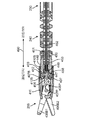
本発明の特徴によれば、外科システム100(図1)は、複数の外科器具101,102,103を含む。外科器具103は、再使用可能な器具部分104と、使い捨て可能な先端部アセンブリ105(チップアセンブリ)(disposable tip assembly)と呼ぶときもある、使い捨て可能な外科器具先端部アセンブリ105とを含む。使い捨て可能な先端部アセンブリ105は、エンドエフェクタアセンブリを含み、次に、エンドエフェクタアセンブリは、クランプ、グラスパ(把持器)、ハサミ、クリップアプライア(clip applier)、又はニードルホルダ(把針器)のような、エンドエフェクタを含む。
In accordance with a feature of the present invention, the surgical system 100 (FIG. 1) includes a plurality of
1つの特徴において、使い捨て可能な先端部アセンブリ105は、使い捨て可能な先端部アセンブリ105を再使用可能な器具部分104に係止(ロック)する係止先端部カバー(係止チップカバー)(locking tip cover)を含む。図1において、使い捨て可能な先端部アセンブリ105は、再使用可能な器具部分104の遠位端にある先端部インターフェース(チップインターフェース)(tip interface)に取り付けられて係止される。図1において、遠位方向は、使い捨て可能な先端部アセンブリ105を取り付ける外科器具の端に向かい、近位方向は、バックエンド機構120(後端機構)に向かう。
In one aspect, the
再使用可能な器具部分104の先端部インターフェースに使い捨て可能な先端部アセンブリ105を取り付けるのを容易化するために、使い捨て可能な先端部アセンブリ105は、第1のクイック接続/切断要素を含み、先端部インターフェースは、第2のクイック切断/切断要素を含む。第2のクイック接続/切断要素は、腱(テンドン)に連結される。腱は、腱を押したり引いたり(プッシュプル)する力をもたらす、アクチュエータアセンブリにも連結される。
To facilitate attaching the
以下により完全に説明するように、腱は、第2のクイック接続/切断要素を、先端部インターフェースの遠位端を越えて押す。第1のクイック接続/切断要素は、露出される第2のクイック接続/切断要素に連結される(coupled)、例えば、噛み合わせられる(mated)。次に、腱は、噛み合あわせられた対の要素を、先端部インターフェース内の、中央管腔と呼ぶことがある通路内に引っ張る。 As described more fully below, the tendon pushes the second quick connect / cut element past the distal end of the tip interface. The first quick connect / disconnect element is coupled, eg, mated, to the exposed second quick connect / disconnect element. The tendon then pulls the mated pair of elements into a passage in the tip interface, sometimes referred to as the central lumen.
次に、係止先端部カバーは、ストップ(停止部)に達するまで近位に移動させられ、次に、係止先端部カバーは、先端部インターフェースに係止され、例えば、先端部カバーは、先端部インターフェースに対して回転させられる。1つの特徴において、係止先端部カバーは、2つの部品、即ち、外部カバー及び係止装置を含む。係止装置は、外部カバーの近位部分内に位置付けられる。 The locking tip cover is then moved proximally until a stop is reached, then the locking tip cover is locked to the tip interface, for example, the tip cover is Rotated relative to the tip interface. In one feature, the locking tip cover includes two parts: an outer cover and a locking device. The locking device is positioned within the proximal portion of the outer cover.
1つの特徴において、エンドエフェクタアセンブリ及びアクチュエータロッドアセンブリの組み合わせは、再使用可能な器具部分の遠位端で先端部インターフェースに装着される。組み合わせが装着された後に、係止先端部カバーは、エンドエフェクタアセンブリに装着され、先端部インターフェースに係止される。他の特徴において、係止先端部カバーは、エンドエフェクタアセンブリ及びアクチュエータロッドアセンブリの組み合わせに装着されて、単一のアセンブリを形成する。次に、この単一のアセンブリは、再使用可能な器具部分の遠位端で先端部インターフェースに装着される。よって、第1の実施例において、係止先端部カバーは事前装着されず、第2の実施例において、係止先端部カバーは事前装着される。 In one feature, the end effector assembly and actuator rod assembly combination is attached to the tip interface at the distal end of the reusable instrument portion. After the combination is mounted, the locking tip cover is mounted on the end effector assembly and locked to the tip interface. In other features, the locking tip cover is attached to the combination of the end effector assembly and the actuator rod assembly to form a single assembly. This single assembly is then attached to the tip interface at the distal end of the reusable instrument portion. Thus, in the first embodiment, the locking tip cover is not pre-mounted, and in the second embodiment, the locking tip cover is pre-mounted.
他の特徴において、係止先端部カバーは、単一の構成部品である。例えば、外部カバーは用いられず、よって、係止先端部カバーは、係止装置である。以下に記載するように、外部カバーは、1つの特徴において、電気絶縁をもたらす。電気絶縁が必要とされないならば、係止装置のみを係止先端部カバーとして用い得る。他の実施例において、係止先端部カバーは、外部カバーの機能性及び係止装置の機能性の両方をもたらす、単一の統合部品−一体成形部品−である。 In other features, the locking tip cover is a single component. For example, no external cover is used, so the locking tip cover is a locking device. As described below, the outer cover in one aspect provides electrical insulation. If electrical insulation is not required, only the locking device can be used as the locking tip cover. In other embodiments, the locking tip cover is a single integrated part—a single piece part that provides both the functionality of the outer cover and the functionality of the locking device.
エンドエフェクタアセンブリは、エンドエフェクタボディアセンブリ(エンドエフェクタ本体アセンブリ)と、エンドエフェクタとを含む。エンドエフェクタは、エンドエフェクタボディアセンブリに連結される。エンドエフェクタボディアセンブリは、外部カバー内に取り囲まれる。エンドエフェクタボディアセンブリは、係止装置がエンドエフェクタボディアセンブリに対して2つの自由度を有するよう、係止装置の中央管腔内に取り付けられる。 The end effector assembly includes an end effector body assembly (end effector body assembly) and an end effector. The end effector is coupled to the end effector body assembly. The end effector body assembly is enclosed within the outer cover. The end effector body assembly is mounted within the central lumen of the locking device such that the locking device has two degrees of freedom relative to the end effector body assembly.
使い捨て可能な先端部アセンブリは、エンドエフェクタアセンブリに接続されるアクチュエータロッドアセンブリも含む。アクチュエータロッドアセンブリは、アクチュエータロッドアセンブリの近位端に第1のクイック接続/切断要素を含む。 The disposable tip assembly also includes an actuator rod assembly connected to the end effector assembly. The actuator rod assembly includes a first quick connect / disconnect element at the proximal end of the actuator rod assembly.
使い捨て可能な先端部アセンブリ105の第1のクイック接続/切断要素と先端部インターフェースの第2のクイック接続/切断要素との噛み合わせ(mating)は、エンドエフェクタとアクチュエータ駆動アセンブリとの間の機械的な接続を構築する。アクチュエータ駆動アセンブリは、第2のクイック接続/切断要素に接続される腱を押す/引く力を生成する。また、電圧がエンドエフェクタに印可される特徴において、噛合させられるクイック接続/切断要素は、エンドエフェクタと供給電源との間の電気的な経路をもたらす。
The mating of the first quick connect / disconnect element of the
内部シールと組み合わせられる使い捨て可能な先端部アセンブリ105の外部カバーは、アセンブリ内でアセンブリに入る如何なる流体をも封止する。これは、使い捨て可能な先端部アセンブリ105の電気的に通電される部分からの流路が、意図されないルートに沿って患者に達するのを防止し、流体が外科器具の他の部品に達するのを防止する。また、外部カバーは、電圧がエンドエフェクタに印可されるときにエネルギを供給することが意図されないアセンブリの部分のために、電気絶縁をもたらす。
The outer cover of the
モノポーラの湾曲したハサミを備える全体的に再使用可能な外科器具は、最も非常に利用されるロボット外科器具の種類のうちの1つである。電圧が湾曲したハサミに印可される。 Overall reusable surgical instruments with monopolar curved scissors are one of the most highly utilized robotic surgical instrument types. A voltage is applied to the curved scissors.
残念なことに、再使用可能なモノポーラの湾曲したハサミの切断性能は、一回使用の(使い捨ての)腹腔鏡器具ほど良くない。何故ならば、主として、鋭利なブレードエッジを通じる電流密度はブレードを鈍くするからである。結果的に、ブレードの鋭利さは、再使用可能な器具の寿命に亘って低下する。再使用可能な器具の最大寿命は、鋭利なブレードを維持する能力によって決定される。 Unfortunately, the cutting performance of reusable monopolar curved scissors is not as good as a single use (disposable) laparoscopic instrument. This is mainly because the current density through the sharp blade edge makes the blade dull. As a result, the blade sharpness decreases over the life of the reusable instrument. The maximum life of a reusable instrument is determined by its ability to maintain a sharp blade.
1つの特徴において、外科器具103は、使い捨て可能な先端部アセンブリ105を含み、次に、使い捨て可能な先端部アセンブリ105は、使い捨て可能なブレードセットを含む。1つの特徴において、使い捨て可能な先端部アセンブリ105は、単一の処置のために用いられ、次に、処分される、例えば、アセンブリ105は、一回使用(single-use)の使い捨て可能な(disposable)先端部アセンブリである。
In one aspect, the
しかしながら、幾つかの状況において、使い捨て可能なブレードセットは、単一の処置よりも多くのために満足に作動することがある。そのような状況において、使い捨て可能な先端部アセンブリ105は、各処置の後に、先端部アセンブリが適切に洗浄され且つ殺菌されるならば、1回の処置よりも多くのために用いられてよい。使い捨て可能な先端部アセンブリ105が1回の処置よりも多くのために用いられるときには、新しい先端部カバーが各処置のために用いられる。この多使用用途において、使い捨て可能な先端部アセンブリ105は、ブレードセットの性能が外科医にとって不満足になるまで使われ、次に、再使用可能な外科器具部分104から取り外され、廃棄される。
However, in some situations, the disposable blade set may operate satisfactorily for more than a single procedure. In such a situation, the
使い捨て可能な先端部アセンブリ105は、使用者に鋭利なブレードをもたらすのみならず、再使用可能な器具部分104の寿命も延ばす。ブレードセットが鈍くなるときに外科器具103の再使用可能な部分が廃棄されなければならないことは最早ない。よって、使い捨て可能な先端部アセンブリ105の使用は、外科器具103についての処置毎の費用を減少させることがある。何故ならば、均等な全体的に再使用可能な外科器具よりも多くの処置において器具部分104を用い得るからである。使い捨て可能な先端部アセンブリ105の増分費用は、再使用可能な器具部分104の寿命の延長によって相殺されることがある。
The
以下により完全に記載するように、使い捨て可能なブレードセットを備える使い捨て可能な先端部アセンブリ105は、クイック接続/切断要素を用いて再使用可能な器具部分104に迅速且つ容易に装着され且つ再使用可能な器具部分104から迅速且つ容易に取り外される。クイック接続/切断は、係止先端部カバーが事前装着されているか否かと無関係に、効率的な使用者ワークフローを可能にする。
As described more fully below, the
また、以下により完全に記載するように、統合先端部カバーは、使い捨て可能な先端部アセンブリ105を再使用可能な器具部分104に締め付け、焼灼エネルギがブレードの意図される部分によってのみ適用されることを保証する。これは使用者ワークフローも単純化し、使い捨て可能な先端部アセンブリ105における構成部品の数を最小限化することによって費用を削減する。この利点は係止先端部カバーが事前装着されているか否かと無関係に当て嵌まる。
Also, as described more fully below, the integrated tip cover clamps the
1つの特徴において、システム100は、Intuitive Surgical, Inc.によって商品化されているda Vinci(登録商標)Surgical Systemである。複数の外科器具101,102,103中の各外科器具は、マニピュレータアーム111,112,113にあるドッキングポート(結合ポート)にそれぞれ取り付けられる。システム100のドッキングポートは、一般的には、器具101,102,103の動作のための機械的な動力をもたらす駆動モータを含む。これらの駆動モータをアクチュエータ駆動アセンブリと呼ぶときがある。各ドッキングポートは、そのドッキングポートに取り付けられる器具と通信するための電気的インターフェースを追加的に含んでよい。
In one aspect, the
システム100は例示的であるに過ぎず、この特定の実施に限定することを意図しない。例えば、使い捨て可能な先端部アセンブリ105を、図1に例示するシステム構成と異なるシステム構成を有する単一の入口ポートを備える遠隔操作される外科システムにおける外科器具にも用い得る。
外科器具103を一例として用いると、再使用可能な器具部分104は、電伝動装置又はバックエンド機構120と、バックエンド機構120から延びるメインチューブ130(主チューブ)と、メインチューブ130の遠位端にある手首機構140(手首機構)とを含む。使い捨て可能な先端部アセンブリ105は、リスト機構140に連結される。
Using
外科器具103も例示的であり、限定的であることを意図しない。例えば、メインチューブ130の遠位端とリスト機構140との間に平行運動機構を含め得る。
駆動ケーブル又は腱及びリスト機構140に接続される導電体がメインチューブ130を通じて延び、バックエンド機構120に繋がる。バックエンド機構120は、典型的には、システム100内の駆動モータへの駆動腱の機械的な連結をもたらす。よって、システム100は、腱内の動き及び張力を所要に制御して、リスト機構140を動かし或いは位置付け、且つ使い捨て可能な先端部アセンブリ105内のエンドエフェクタを作動させ得る。
A conductor connected to the drive cable or tendon and
図1の実施例では、カメラシステム150がシステム100のマニピュレータアームに同様に取り付けられている。立体的又は三次元的であるかもしれないカメラシステム150からの眺望は、マスタ制御コンソール(図示せず)で見られる。システム100の処理システムは、医者又は他の医療関係者がカメラシステム150を見て、器具101,102,103を操作するのを可能にする、ユーザインターフェースをもたらす。
In the embodiment of FIG. 1,
例えば、医療処置を受けている患者の小さな開口部内にカニューレを通じて外科器具103の端を挿入するためにアーム113を用い得る。代替的に、単一ポートシステムにおいて、外科器具103は、カニューレ内に取り付けられる進入ガイド(エントリーガイド)内の通路を通じて挿入される。バックエンド機構120は、リスト機構140及び患者の内側の手術部位にあるエンドエフェクタを作動させるために用いられる。メインチューブ130、リスト機構140、及び使い捨て可能な先端部アセンブリ105の直径又は複数の直径は、一般的には、器具130を共に用いるカニューレの大きさに従って選択され、例示的な実施態様において、リスト機構140及びメインチューブ130は、幾つかの既存のカニューレシステムの大きさに適合するよう、約4mm、5mm、又は8mmの直径である。
For example,
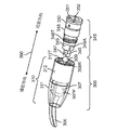
図2は、再使用可能な器具部分204と、再使用可能な器具部分204に付けられる使い捨て可能な先端部アセンブリ205とを含む、再使用可能な外科器具203の遠位端の1つの特徴をより詳細に例示している。再使用可能な器具部分204は、リスト240(手首部)に連結される遠位端を有するメインチューブ230を含む。リスト240の遠位端は、先端部インターフェース245に連結される。矢印290は、再使用可能な外科器具203に対する近位方向及び遠位方向を示している。
FIG. 2 illustrates one feature of the distal end of a reusable
使い捨て可能な先端部アセンブリ205は、先端部インターフェース245に取り付けられ且つ接続される、例えば、この特徴では、再使用可能な器具部分204に付けられる。使い捨て可能な先端部アセンブリ205は、使い捨て可能なブレードアセンブリ206を含む。エンドエフェクタとしてのブレードを備えるブレードアセンブリの使用は例示的であるに過ぎず、この特定のエンドエフェクタに限定することを意図しない。この開示に鑑みれば、当該技術分野に精通した者は、ここに記載する使い捨て可能な先端部アセンブリにおいて、人が選択するエンドエフェクタアセンブリを実施し得る。
The
先端部インターフェース245の一部のみが図2において見える。先端部インターフェース245の残部は、使い捨て可能な先端部アセンブリ205内に収容されている。
Only a portion of the
1つの特徴において、使い捨て可能な先端部アセンブリ205は、一回使用の(使い捨ての)アセンブリである。しかしながら、他の特徴における使い捨て可能な先端部アセンブリ105について上述したように、使い捨て可能な先端部アセンブリ205は、限定的な数の外科処置において、即ち、要素の性能が不満足になるまで用いられ、そして、次に廃棄されてよい。使い捨て可能な先端部アセンブリ205の多使用の特徴では、各外科処置において新しい先端部カバーが用いられ、使い捨て可能な先端部アセンブリ205の他の部品が適切に洗浄され且つ殺菌される。使い捨て可能な先端部アセンブリ205が単一の外科処置において用いられるか或いは数回の外科処置において用いられるかと無関係に、使い捨て可能な先端部アセンブリ205の寿命は、外科器具の、例えば、リスト及びシャフトの寿命よりも少なく、よって、外科器具に対して使い捨て可能である。
In one aspect, the
先端部インターフェース245及び使い捨て可能な先端部アセンブリ205は、リスト240内の最後の関節に対して遠位の長手方向長さを最小限化するように設計される。加えて、以下により完全に説明するように、先端部インターフェース245及び使い捨て可能な先端部アセンブリ205は、使い捨て可能な先端部アセンブリ205への先端部インターフェース245の容易な接続及び切断を許容するように設計される。加えて、先端部インターフェース245及び使い捨て可能な先端部アセンブリ205の組み合わせは、使い捨て可能なブレードアセンブリ206内のブレードに印可されるあらゆる電圧のための電気絶縁をもたらす。電気的に「高温な」(“hot”)流体が意図されない方法において患者と接触せず、再使用可能な器具部分204内に近位に流入しないよう、先端部インターフェース245及び使い捨て可能な先端部アセンブリ205のこの組み合わせは、組み合わせ内のそのような電圧によって創り出されるあらゆる電気的に通電される流体を封止する。
使い捨て可能な先端部アセンブリ205は、先端部インターフェース245を介して、少なくとも、外科器具203への機械的な接続を行う。幾つかの特徴では、電気的な接続も行われる。第1の機械的な接続は、使い捨て可能な先端部アセンブリ205内の機械的なアクチュエータロッドアセンブリと先端部インターフェース245内のグリップアクチュエータ要素との間で行われる。機械的な接続が行われるとき、1つの特徴では、電圧、例えば、約3000ボルトをブレードに印可し得るよう、ブレードアセンブリ206内のブレードと外科器具203のバックエンド機構内の電気コネクタとの間の電気的な接続も構築される。最後に、使い捨て可能な先端部アセンブリ205が先端部インターフェース245に付けられるよう、係止可能な機械的な接続は、使い捨て可能な先端部アセンブリ205を先端部インターフェース245に係止する。
The
1つの特徴において、係止可能な機械的な接続は、部分的な回転接続である、例えば、使い捨て可能な先端部アセンブリ205は、先端部アセンブリ245に取り付けられ、次に、4分の1回転だけ回転させられて、使い捨て可能な先端部アセンブリ205を先端部インターフェース245に係止する。そのような部分的な回転接続の一例は、差込み接続である。他の特徴において、係止可能な機械的な接続は、使い捨て可能な先端部アセンブリ205及び先端部インターフェース245にあるネジ山を用いて実施される。機械的な接続は、係止可能であると考えられる。何故ならば、使い捨て可能な先端部アセンブリ205が先端部アセンブリ245に付けられるとき、ブレードアセンブリ206は所定の場所において係止され、使用の準備ができているからである。
In one feature, the lockable mechanical connection is a partial rotational connection, for example, the
図2において、先端部インターフェース245の近位端には、先端部インターフェース245の外面から径方向に外向きに延びる2つのリブ245R1,245R2がある。リブ245R1,245R2は任意である。シースがリスト機構240の上に用いられるとき、シースの遠位端はリブ245R1,245R2と共にシールを形成する。また、1つの特徴では、リスト機構240を先端部インターフェース245に取り付けるに際して、ピンが先端部インターフェース245の近位端にある2つの開口245OPを通じて挿入される。
In FIG. 2, at the proximal end of the
図3は、先端部インターフェース345に取り付けられ且つ接続されるように構成される使い捨て可能な先端部アセンブリ305の他の特徴を例示している。先端部インターフェース345は、図1及び2に示すような再使用可能な外科器具のリスト又は他の要素に接続可能である。矢印390は、使い捨て可能な先端部アセンブリ305に対する近位方向及び遠位方向を示している。
FIG. 3 illustrates another feature of the
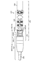
使い捨て可能な先端部アセンブリ305は、使い捨て可能なブレードアセンブリ306と、係止先端部カバー310と、アクチュエータロッドアセンブリ308(図10A乃至10Dを参照)とを含む。以下により完全に説明するように、使い捨て可能なブレードアセンブリ306は、一対のブレードと、Uリンク307(clevis)と、ピン307Pとを含む。
The
また、以下により完全に説明するように、1つの特徴において、係止先端部カバー310は、2つの部品、即ち、外部カバー311及び係止装置312を含む。図3において、外部カバー311は、外部カバー311内に収容される部品を見るのを許容するよう透明に作製される。これは例示の容易さのために過ぎず、外部カバー311が透明である或いは透明でなければならないことを暗示することを意図しない。
Also, as described more fully below, in one aspect, the locking
この特徴において、係止装置312は、円筒形の外面と、近位内面に形成されるネジ山312Tとを有する。1つの特徴において、係止装置312は、Uリンク上で回転自由であるナットである。係止装置312は、非導電性の合成材料で作製される。
In this feature, the
外部カバー311は、シリコーン又は可撓な医療等級の熱可塑性エラストマのような、非導電性の可撓な材料で作製される。熱可塑性エラストマの一例は、The Upjohn Companyによって提供されるPellethane(登録商標)ポリウレタン熱可塑性エラストマ(Pellethane(登録商標)は、Kalamazoo, MichiganのThe Upjohn Companyの米国登録商標である)。
The
非導電性の可撓な材料は、所定の場所に外側被覆(オーバーモールド)され或いは結合され、非導電性の可撓な材料は、患者接触が意図されないアクティブ電極の部分を覆う絶縁バリアとして作用する。この材料はブレードの開放及び閉塞を許容するために可撓である。外部カバー311の近位端も、流体シールとして作用する構成を有し、電気的に高温な流体が意図されない場所で患者と接触するのを防止する。
The non-conductive flexible material is overcoated or bonded in place, and the non-conductive flexible material acts as an insulating barrier over the portion of the active electrode that is not intended for patient contact. To do. This material is flexible to allow blade opening and closing. The proximal end of the
使い捨て可能なブレードアセンブリ306の機械的な作動は、クイック接続/切断インターフェースの一例である、ボールアンドソケットインターフェース(ball and socket interface)を通じてもたらされる。アクチュエータロッド308Rの近位端にあるボール309が、グリップアクチュエータ要素346の遠位端に配置されるソケット347内に適合する。ボール309及びソケット347は、それぞれ、第1のクイック接続/切断要素及び第2のクイック接続/切断要素の一例である。ボール309及びソケット347の使用は例示に過ぎず、限定的であることを意図しない。この開示に鑑みれば、当該技術分野に精通した者は、クイック接続/切断インターフェースと関連付けられる他の構成、例えば、隅肉付きエッジを備えるシリンダ(cylinder with filleted edges)を維持しながら、ここに記載する接続/切断機能性をもたらす2つの要素を備えるクイック接続/切断インターフェースを実施し得る。
Mechanical actuation of the
接続/切断インターフェースの1つの特徴は、インターフェースが回転自由度を有すること、例えば、ボール309をソケット347内で回転させ得ることである。メインチューブ230が回転させられると、接続/切断インターフェースに接続される腱は近位端に固定される。接続/切断インターフェースの回転自由度は、回転自由度を有さないインターフェースに接続される腱に比べて、腱のねじり剛性の減少を可能にする。
One feature of the connect / disconnect interface is that the interface has rotational freedom, for example, the
グリップアクチュエータ要素346は、器具先端部348(器具チップ)(instrument tip)の管腔内に位置付けられて長手に摺動し、腱352に連結される。リスト−使い捨て可能な先端部アダプタ350(チップアダプタ)(tip adapter)が、器具先端部348の近位端に付けられる。シール(図3には示されていない)が、器具先端部348の近位端とリスト−使い捨て可能な先端部アダプタ350との間に位置付けられる。シールはリスト及びメインチューブを電気的に「高温な」流体から隔離する。さもなければ、流体は使い捨て可能な先端部アセンブリ305を通過して器具先端部348の中央管腔内に至ることがある。腱352が、リスト−使い捨て可能な先端部アダプタ350の近位端で中央管腔内に取り付けられるガイド(図示せず)を通過する。1つの特徴において、ガイドは、可撓なブッシング(bushing)として実施される。腱352はリストを通過し、よって、可撓である。
The
器具先端部348の遠位端は、向き整列構成(向きアライメント構成)、この実施例では、平坦な表面349Aを含む。対応する向き整列構成が、Uリンク307の近位端に設けられる。2つの向き整列構成は、器具先端部348が使い捨て可能な先端部アセンブリ305に付けられるときに、使い捨て可能な先端部アセンブリ305が再使用可能な外科器具部分上で適切に方向付けられるよう噛み合う(対になる)。
The distal end of
単一の平坦な表面の使用は例示的であるに過ぎず、限定的であることを意図しない。他の特徴では、向き整列構成として、2つの対向する平坦な表面が用いられる。用いられる具体的な整列構成は、使い捨て可能な先端部(チップ)(tip)のエンドエフェクタの特徴に依存する。モノポーラの湾曲した剪断器(シャー)のためには、単一の平坦な表面が用いられる。何故ならば、エンドエフェクタは非対称的であり、特異な向きにおいて装着される必要があるからである。エンドエフェクタを2つの向きのうちの1つにおいて装着し得るならば、2つの対向する平坦な表面を向き整列構成として用い得る。この開示に鑑みれば、当該技術分野に精通した者は、向き整列構成に関してここに記載する機能性をもたらす如何なる向き整列構成をも用い得る。 The use of a single flat surface is exemplary only and is not intended to be limiting. In other features, two opposing flat surfaces are used as an orientation alignment configuration. The specific alignment configuration used depends on the end effector characteristics of the disposable tip. For a monopolar curved shear, a single flat surface is used. This is because the end effector is asymmetric and needs to be mounted in a specific orientation. If the end effector can be mounted in one of two orientations, two opposing flat surfaces can be used as the orientation alignment configuration. In view of this disclosure, those skilled in the art may use any orientation arrangement that provides the functionality described herein with respect to the orientation arrangement.
器具先端部348は、係止インターフェース要素、例えば、ネジ山312Tと噛み合う該表面上のネジ山348Tも有する。ネジ山は、使い捨て可能な先端部アセンブリ305を先端部インターフェース345に係止するために用いられる。
The
図4A、5A、6A、7A、及び9Aは、使い捨て可能な先端部アセンブリ205を再使用可能な器具部分204に接続することを例示している。図4B、5B、6B、7B、8、及び9Bは、それぞれ、図4A、5A、6A、7A、2、及び9A中の要素の断面図である。
4A, 5A, 6A, 7A, and 9A illustrate connecting the
図4Aにおいて、使い捨て可能な先端部アセンブリ205は、再使用可能な器具部分204への接続のために位置付けられている。図4Bは、対応する断面図である。ソケット447が器具先端部448の遠位端の遠位に位置付けられるよう、グリップアクチュエータ要素446が器具先端部448内の管腔457から押し出されている。図4A及び4Bでは、矢印490によって示すように、遠位方向は、使い捨て可能なブレードアセンブリ206におけるブレード406B1及び406B2の先端部に向かい、近位方向は、外科器具203のバックエンド機構に向かう。1つの特徴において、グリップアクチュエータ要素446は、使い捨て可能な先端部アセンブリ205のボール409を受け入れるよう、グリップアクチュエータ要素446の通常閉塞位置(図2を参照)から約0.18インチ(4.5mm)だけ動かされる。
In FIG. 4A,
図4Bに示すように、使い捨て可能なブレードアセンブリ206は、第1のピン407PによってUリンク407に接続される2つのブレード406B1及び406B2を含む。アクチュエータロッドアセンブリ408の第2のピン408Pが、ブレード406B1及び406B2の近位端にあるスロット内に位置付けられる。第2のピン408Pがスロット内で動かされてブレードを作動させる。1つの特徴において、第2のピン408Pは、アクチュエータロッドアセンブリ408内の中実な円筒形ロッド408Rの遠位端を貫通し且つ遠位端内を浮動する。
As shown in FIG. 4B, the
1つの特徴において、ブレード406B1及び406B2は、ここでは17−4ステンレス鋼と呼ぶ、H900に調節された17−4PHステンレス鋼で作製される、モノポーラ湾曲ブレードである。1つの特徴において、ブレード406B1及び406B2は、放電加工(EDM)を用いて形成される。他の特徴において、ブレード406B1及び406B2は、301ステンレス鋼から打ち抜かれる。 In one feature, blades 406B1 and 406B2 are monopolar curved blades made of 17-4PH stainless steel tuned to H900, referred to herein as 17-4 stainless steel. In one feature, blades 406B1 and 406B2 are formed using electrical discharge machining (EDM). In other features, blades 406B1 and 406B2 are stamped from 301 stainless steel.
ブレード406B1及び406B2は薄く、例えば、約0.020インチ(0.5mm)の厚さを有する。ブレード406B1及び406B2の切断表面は、1つの特徴において開放されるときに、約0.35インチ(8.9mm)の露出させられる切断表面の長さを有する。この特徴において、遠位端からUリンクピン407Pまでのブレードの長さは、約0.50インチ(12.7mm)である。ブレード406B1及び406B2は僅かに湾曲させられ、偏り(バイアス)をもたらすよう撓まされる。1つの特徴において、ブレード湾曲の半径は、約0.35インチ(8.9mm)である。
Blades 406B1 and 406B2 are thin, for example, about 0.020 inches (0.5 mm) thick. The cutting surfaces of blades 406B1 and 406B2 have an exposed cutting surface length of about 0.35 inches (8.9 mm) when opened in one feature. In this feature, the length of the blade from the distal end to the
ブレードは通常は互いに干渉し合うが、ブレードを組み立てるために、ブレードは曲がらなければならない。ブレードを曲げるのに必要とされる力は、1つの特徴において、ブレードの間のバイアス力(偏り力)をもたらすものである。この力は、ブレード幾何学的構成(湾曲)、ブレード厚さ、及びスエージ加工処理中に構築されるブレード積重ねとUリンク407のアームとの間の間隙の関数である。このバイアス(偏り)は、外科ハサミにおいて典型的に見出されるバイアスばね(偏りばね)の必要を排除する。しかしながら、幾つかの特徴では、皿ばねのようなバイアスばねによってバイアスをもたらし得る。 The blades usually interfere with each other, but in order to assemble the blades, the blades must bend. The force required to bend the blades, in one aspect, provides a biasing force (biasing force) between the blades. This force is a function of the blade geometry (curvature), blade thickness, and the gap between the blade stack and U-link 407 arm built during the swaging process. This bias eliminates the need for bias springs (bias springs) typically found in surgical scissors. However, in some features, the bias can be provided by a bias spring such as a disc spring.
非導電性材料及び導電性材料でUリンク407を作製し得る。Uリンク407に適した非導電性材料は、例えば、ガラス充填ポリフタルアミド(PPA)で作製される。ガラス充填材料は、十分な強度、生体適合性、殺菌適合性を有し、PPAは、極めて良好な耐アークトラッキング性(arc tracking resistance)を有し、それは高電圧モノポーラ焼灼において有利である。適切なPPAは、Amodel(登録商標)PPA A-1133 HSの下でSolvay Plasticsから入手可能である。(Amodel(登録商標)は、Alpharetta, GeorgiaのSolvay Advanced Polymers, L.L.C.の米国登録商標である。)非導電性Uリンク407は、電圧がブレード406B1及び406B2に印可されるときにブレード406B1及び406B2及び/又はアクチュエータロッドアセンブリ408から患者及び/又は器具の本体への如何なる意図されないアーク経路をも伸長させる。
The U link 407 can be made of a non-conductive material and a conductive material. A suitable non-conductive material for the
しかしながら、幾つかの特徴では、Uリンク407を伝導性材料で作製し得る。導電性Uリンク407は、例えば、ステンレス鋼である。1つの特徴では、17−4ステンレス鋼が用いられる。しかしながら、金属射出模型製作(metal injection modeling)において用い得る如何なるステンレス鋼をも用い得る。 However, in some features, the U link 407 can be made of a conductive material. The conductive U link 407 is, for example, stainless steel. In one feature, 17-4 stainless steel is used. However, any stainless steel that can be used in metal injection modeling can be used.
1つの特徴において、アクチュエータロッドアセンブリ408は、17−4ステンレス鋼で作製され、中実な円筒形ロッド408Rを含み、円筒形ロッド408Rの近位端にボール409を備える。1つの特徴において、アクチュエータロッドアセンブリ408の全長は、0.28インチ(7.1mm)である。円筒形ロッド408Rの直径は0.090インチ(2.28mm)であり、長さは0.28インチ(7.1mm)である。1つの特徴において、ボール409は、0.70インチ(17.8mm)の直径を有する。また、1つの特徴において、ボール409の裏側−近位側−は、部品の製造を助けるよう、小さな平坦領域を有する。ネック領域408Nとボール409との間には移行領域408Tがある。移行領域408Tは、直径を円筒形ロッド408Rの直径まで減少させる。
In one feature, the
係止先端部カバー410は、使い捨て可能な先端部アセンブリ205の電気的に高温のアクティブ構成部品と患者の意図されない接触との間の電気絶縁シール構成部品をもたらす。電気絶縁シール構成部品は、剛的な非導電性構成部品、即ち、係止装置412を含み、それは使い捨て可能な先端部アセンブリ205を器具先端部448及び外側被覆シール、例えば、外部カバー411内に配置する。このシールは、使い捨て可能な先端部アセンブリ205に入る流体のための絶縁バリア構成部品ももたらす。
Locking
1つの特徴において、係止装置412は、アモルファス熱可塑性ポリエーテルイミド(PEI)材料を用いて成形される。アモルファス熱可塑性PEI材料の一例は、Saudi Basic Industries Corporation (SABIC)によって製造されるULTEM(登録商標)アモルファス熱可塑性PEI材料である。(ULTEM(登録商標)は、SABIC Innovative Plastics, Inc. besloten vennootschap (b.v.) NETHERLANDS Plasticslaan 1 Bergen op Zoom NETHERLANDS 4612PXの米国登録商標である。)他の特徴において、係止装置412は、上述のようなガラス充填ポリフタルアミド(PPA)を用いて成形される。
In one feature, the
1つの特徴において、外部カバー411は、高い引裂き強度を備えるシリコーンゴム、例えば、耐引裂き性シリコーンエラストマで作製される。シリコーンゴムは、生体適合性があり、少なくとも4kVに耐える。加えて、シリコーンの耐高温性は、エネルギがブレードに適用されるときに生成されることがある如何なる熱に関しても有利である。そのようなシリコーンゴムの一例は、Silastic(登録商標)Biomedical Grade ETR Elastomer Q7-4750のようにDow Corning Corporationによって販売されている。(Silastic(登録商標)は、Midland, MichiganのDow Corning Corporationの米国登録商標である。)他の適切な材料は、Upjohn Companyによって提供されるPellethane(登録商標)ポリウレタン熱可塑性エラストマのような、ポリウレタン熱可塑性エラストマを含む、可撓な医療等級のエラストマを含む。ここで提供される如何なる材料及び如何なる寸法も例示的であるに過ぎず、それらの特定の寸法及び材料に限定することを意図しない。
In one feature, the
使い捨て可能な先端部アセンブリ205は、長手軸491を有する。係止装置412は、長手軸491の周りで回転自在であり、よって、Uリンク407の周りで回転自在である。この特徴において、係止装置412は、図4Bの断面図において平坦である内周面412Aを有し、内周面412Aは、係止装置412の近位端から内周面412Aに対して垂直に形成されるショルダ412B(肩部)まで遠位に延びる。
The
長手軸491に対して実質的に平行な内面412A(内周面)の長さは、少なくとも2つの基準に基づき選択される。第1に、内面412Aの長さは、係止先端部カバー410が、近位ストップに当たるよう遠位に動かされるときに、ボール409が、図4A及び4Bに示すように、カバー411を越えて延びるような長さである。1つの特徴において、内周面412Aから延びる雄の差込み要素(図7Dの要素712を参照)は、係止先端部カバー410が捕らえられるよう、Uリンク407と干渉する。第2に、以下に記載するように、使い捨て可能な先端部アセンブリ205が再使用可能な器具部分204上に取り付けられ(mounted)且つ再使用可能な器具部分204に付けられる(affixed)よう、使い捨て可能な先端部アセンブリ205が近位に動かされるとき、その長さは、表面407Aの遠位縁にあるショルダ407Bがショルダ412Bに当接するような長さである(図8を参照)。
The length of the
図4Bに示す表面412A及びショルダ412Bの構成は例示的であるに過ぎず、限定的であることを意図しないことが理解されるべきである。一般的には、係止装置412の内面412A(内側表面)及びショルダ412Bは、記載したばかりの機能性をもたらすよう、Uリンク407の外面407A及びショルダ407Bと協働するように選択される。一般的には、係止装置412及びUリンク407の両方にあるショルダは、2つの構成部品が共に引っ張られて、係止装置412が作動させられるときに、Uリンク407を所定の場所に係止するように設計される。
It should be understood that the configuration of
係止装置412は、以下により完全に記載するような4分の1回転式の構成又は差込式の取付具の使用を通じて使い捨て可能な先端部アセンブリ205を器具先端部448に掛止するために用いられる、内面412Aから径方向に内向きに延びる2つの突起712(図7D)を含む。4分の1回転係止機構の使用は、表面412Aの長さがネジ山付き構成に対して最小限化されることを可能にし、よって、最終の関節に対して遠位の使い捨て可能な先端部アセンブリ205の非関節接続される長さを最小限化するのに役立つ。加えて、4分の1係止機構の使用は、係止装置412の外径を減少させ、よって、使い捨て可能な先端部アセンブリ205の外側の最大外径を減少させるのに役立つ。
The
先端部インターフェース245は、器具先端部448を含む。器具先端部448は、中央管腔457を有し、グリップアクチュエータ要素446が、中央管腔457内に位置付けられる。器具先端部448の遠位端は、向き整列構成449を含み、この実施態様では、平坦な表面449Aを含む。対応する向き整列構成(図4Aでは見えない)が、Uリンク407の近位端に設けられる。器具先端部448が使い捨て可能な先端部アセンブリ205に付けられるときに、使い捨て可能な先端部アセンブリ205が再使用可能な器具部分204上で正しく方向付けられるよう、2つの向き整列構成は噛み合う。
The
この特徴において、器具先端部448にある平坦な表面449Aに対する近位には、係止インターフェース要素、例えば、雌の差込みレセプタクル448B(差込み受部)がある。1つの特徴において、器具先端部448は、上述のガラス充填ポリフタルアミドのような非導電性の剛性材料で作製される。電気アークトラッキングが懸念でないならば、代替的な材料は、ポリエーテルエーテルケトン(PEEK)のような有機ポリマ熱可塑性物質である。また、電気絶縁が必要とされないならば、器具先端部448を医療等級ステンレス鋼で作製し得る。
In this feature, proximal to the
1つの特徴において、向き整列構成449の最大直径は、0.160インチ(4.06mm)であり、平坦な表面は、0.065インチ(1.65mm)の長手方向における長さと、0.068インチ(1.72mm)の長手方向に対して垂直な方向における長さとを有する。レセプタクル448Bの領域における器具先端部448の外径は、0.215インチ(5.45mm)である。管腔457は、0.10インチ(2.54mm)の内径を有する。上記のように、特定の材料及び大きさの引用は例示的であるに過ぎず、これらの特定の材料及び大きさに限定することを意図しない。
In one aspect, the maximum diameter of the
グリップアクチュエータ要素446は、要素458と呼ぶことがあるグリップ駆動要素458を含み、それはグリップアクチュエータ絶縁体453の管腔内に取り付けられる。グリップアクチュエータ絶縁体453は、器具先端部448の中央管腔457内で長手方向に摺動する。グリップアクチュエータ絶縁体453の外面は、ダンベル形状を有し、例えば、外面の中央部分は、外面の近位端部分及び遠位端部分に対して凹まされる。
The
シール454が、グリップアクチュエータ絶縁体453の外面の中央部分の周りに延在する。シール454は、器具先端部448の内壁とグリップアクチュエータ絶縁体との間のシールを形成する。よって、シール454は、リスト及びメインチューブを、使い捨て可能な先端部アセンブリ205を通過する電気的に高温な流体から隔離する。シール454は、器具先端部448の長手軸492と平行に動き、よって、最後の関節に対して遠位の非関節接続される長さを減少させるのに役立つ。1つの特徴において、シール454は、上述した耐引裂き性シリコーンエラストマで作製される。この特徴において、グリップアクチュエータ絶縁体453は、上述したガラス充填ポリフタルアミドで作製される。
A
この特徴において、グリップ駆動要素458は、上述した17−4ステンレス鋼で作製される。グリップ駆動要素458は、グリップ駆動要素458の近位端から延びる中央管腔を有する。要素458の近位部分は、ソケット447である。ソケット447は、ボール409と噛み合う(対になる)大きさ及び構成にされる。
In this feature, the
ハイポチューブ455(hypotube)、例えば、アグレット(aglet)が、腱452の遠位端にクリンプされる(crimped)。ハイポチューブ及び腱の組み合わせは、グリップ駆動要素458の中央管腔内に挿入され、次に、後に、グリップアクチュエータ要素458に溶接される。代替的に、ハイポチューブを所定の場所にクリンプし得る。グリップアクチュエータ絶縁体453は、グリップ駆動要素458に結合される。他の特徴では、ハイポチューブ455がグリップ駆動要素458に固定された後に、グリップアクチュエータ絶縁体453は、グリップ駆動要素458の上に外側被覆される。
A
1つの特徴において、腱452は、電気絶縁シース(ジャケット)内に収容される編みタングステンケーブルである。1つの特徴において、シースはエチレン4フッ化エチレン(ETFE)のようなフルオロポリマ(フッ素重合体)のチューブである。絶縁特性に加えて、シースは腱452のプッシュ/プル剛性を増大させ、よって、腱452の座屈(バックリング)を減少させるのに役立つ。
In one feature, the
リスト−使い捨て可能な先端部アダプタ450が、器具先端部448の近位端に付けられる。シース456を備える腱452は、リスト−使い捨て可能な先端部アダプタ450の中央管腔内に取り付けられるガイド451を通過する。1つの特徴において、ガイド451は、可撓なブッシングとして実施される。ガイド451は、ポリテトラフルオロエチレン(PTFE)又はフッ素化エチレンプロピレン(FEP)のようなフルオロポリマを用いて成形される。
A wrist-
図4A及び4Bでは、ノブ(図11)又はレバーが動かされ、次いで、それは、ソケット447が器具先端部448の遠位端を越えて押されるよう、腱452を径方向において動かす。上記のように、係止先端部カバー410も、Uリンク407がストップ、例えば、外部カバー411の近位側面に接触するまで、径方向に動かされる。これはボール409を露出させる。使用者は、再使用可能な器具部分204への使い捨て可能な先端部アセンブリ205の取り付けを開始するために噛み合わされなければならない、2つのクイック接続/切断構成部品(迅速接続/切断構成部品)、即ち、ボール409及びソケット447を見ることができる。
In FIGS. 4A and 4B, the knob (FIG. 11) or lever is moved, which then moves the
図5A及び5Bにおいて、ボール409はソケット447内に配置されている。この実施例において、ボール409は、器具先端部448の長手軸492に対してある角度でソケット447内に位置付けられる。ボール409がソケット447内にある状態の図6A及び6Bにおいて、使い捨て可能な先端部アセンブリ205は、先端部205の長手軸491が器具先端部448の長手軸492と位置合わせされる(整列させられる)ように動かされている。
In FIGS. 5A and 5B, the
図6A中の腱452が近位方向に引っ張られるとき、使い捨て可能な先端部アセンブリ205は近位方向に引っ張られる。使い捨て可能な先端部アセンブリ205は近位方向に動くとき、向き整列構成449は、使い捨て可能な先端部アセンブリ205における対応する構成と位置合わせされる。使い捨て可能な先端部アセンブリ205における対応する構成との向き整列構成449の整列は、2つの構成部品が適切に方向付けられることを保証する。
When the
故に、図7A及び7Bに例示するように、グリップアクチュエータ絶縁体453が中央管腔457の近位端に向かう進行の限界に達するとき、ボール409及びソケット447、ロッド408Rの近位部分、及びグリップアクチュエータ要素446は、中央管腔457の内側に位置付けられる。向き整列構成は、Uリンク407の近位端が器具先端部448の遠位端と噛み合った(対になった)と推定する。
Thus, as illustrated in FIGS. 7A and 7B, when the
図7Cは、係止先端部カバー410が取り外された状態の図7A及び7Bにおける構成の斜視図である。図7Cは、噛み合い後に、器具先端部448にある雌の差込みレセプタクル448Bの第1の部分と位置合わせされた、Uリンク407の差込み案内構成407Cを示している。係止装置412の1つの突起712(図7D)が、Uリンク407のショルダ407Bが係止装置412のショルダ412Bに当接するまで、Uリンク407の差込み案内構成407C及び雌の差込みレセプタクル448Bによって形成される通路を通じて摺動させられる。次に、この特徴において、係止装置412は時計回りに回転させられて、雌の差込みレセプタクル448Bの第2の部分に至る。その回転は、再使用可能な器具部分204の遠位端で、係止先端部カバー410を先端部インターフェース245に係止する。
FIG. 7C is a perspective view of the configuration in FIGS. 7A and 7B with the locking
上記のように、図2は、再使用可能な器具部分204に取り付けられ且つ係止される係止先端部カバー410の例示である。図8は、図2の断面の例示である。図8は、ブレード406B1,406B2と、アクチュエータロッドアセンブリ408と、グリップアクチュエータ要素446と、腱452との間の機械的な接続を示している。この機械的な接続は、腱452のプッシュプル作用による、以下により完全に記載するような、ブレード406B1,406B2の機械的な作動を許容する。
As described above, FIG. 2 is an illustration of a
例えば、使い捨て可能なブレードアセンブリ206が、使い捨て可能なモノポーラ湾曲ハサミアセンブリであるときには、使い捨て可能な先端部アセンブリ205と再使用可能な器具部分204との間に電気的な接続が存在する。この電気的な接続は、機械的な接続及び作動のために用いられるボール及びソケット接続を通じて行われる。ブレード406B1,406B2と器具関節との間の絶縁を維持するために、器具先端部448は、非導電性材料で作製される。加えて、要求はされないが、Uリンク407を非導電性材料で作製することは、ブレード406B1,406B2の露出部分と器具関節との間の如何なる潜在的なアーク経路をも伸長させる。よって、使い捨て可能な先端部アセンブリ205と使い捨て可能な先端部インターフェース245の係止される組み合わせは、構成部品の間の電気的な接続及び電気的な絶縁の両方をもたらす。
For example, when the
使い捨て可能な先端部アセンブリ205及び使い捨て可能な先端部インターフェース245の係止される組み合わせは、電気的に高温なアクティブ電極と患者との間の流体のための絶縁バリアを創り出す絶縁シール454ももたらす。1つの特徴において、外部カバー411は、使い捨て可能な先端部インターフェース245の近位端で、外側被覆されるシール410Sをもたらす。シール410Sは、カバー411のリップ(lip)と器具先端部448の外周面との間に形成される。
The locked combination of
図8では、腱ガイド451をより詳細に示している。図8は、腱ガイド451が、リスト−使い捨て可能な先端部アダプタ450内の管腔からリスト240及びメインチューブ230を通じて近位に延びることを示している。1つの特徴において、腱ガイド451は、メインチューブ230の近位端に対して近位に延びる。
FIG. 8 shows the
図9A及び9Bにおいて、腱452は、アクチュエータ駆動アセンブリ(図示せず)によって遠位に押される。腱452の動作は、グリップアクチュエータ要素446を器具先端部448の中央管腔457内で遠位に押す。グリップアクチュエータ要素446の動作は、アクチュエータロッドアセンブリ408を遠位に押す。ピン408Pは、ブレード406B1,406B2のスロット内で摺動し、次いで、それはブレード406B1,406B2をピン407Pについて旋回させ、図9A及び9Bに示すように、開放させる。腱452が近位に引っ張られるとき、ブレード406B1,406B2は閉塞する。
In FIGS. 9A and 9B,
図10A乃至10Dは、先端部インターフェース345及び使い捨て可能な先端部アセンブリ305の断面図である。図10A乃至10Dは、使い捨て可能な先端部アセンブリ305への先端部インターフェース345の接続を例示している。これらの図面には示されていないが、先端部インターフェース345は、再使用可能な外科器具部分204と同様に、再使用可能な器具部分の遠位端に配置される。
FIGS. 10A-10D are cross-sectional views of the
図10Aにおいて、使い捨て可能な先端部アセンブリ305(図3)が、先端部インターフェース345への接続のために位置付けられる。ソケット347が器具先端部348の遠位端の遠位に位置付けられるよう、グリップアクチュエータ要素346(図10A)が器具先端部348の中央管腔357内に摺動させられる。図10A乃至10Dでは、矢印1090によって示すように、遠位方向は、使い捨て可能なブレードアセンブリ306におけるブレード306B1及び306B2の先端部に向かい、近位方向は、リスト−使い捨て可能な先端部アダプタ350に向かう。1つの特徴において、グリップアクチュエータ要素346は、使い捨て可能な先端部アセンブリ305のボール309を受けるよう、グリップアクチュエータ要素346の通常の閉塞位置(図10Dを参照)から約0.18インチ(4.57mm)だけ動かされる。
In FIG. 10A, disposable tip assembly 305 (FIG. 3) is positioned for connection to tip
図10Aに示すように、使い捨て可能なブレードアセンブリは、第1のピン307PによってUリンク307に接続される2つのブレード306B1及び306B2を含む。ピン308Pがスロット内で動かされてブレードを作動させるよう、第2のピン308Pがブレード306B1及び306B2の近位端にあるスロット内に位置付けられる。第2のピン308Pは、アクチュエータロッドアセンブリ308における中実な円筒形ロッド308Rの遠位端を貫通し且つ遠位端内を浮動する。
As shown in FIG. 10A, the disposable blade assembly includes two blades 306B1 and 306B2 connected to the U link 307 by a
1つの特徴において、ブレード306B1及び306B2は、ブレード406B1及び406B2と均等なモノポーラ湾曲ブレードである。Uリンク307を非導電性材料又は導電性材料で作製し得る。Uリンク307に適する非導電性材料は、上述のガラス充填ポリフタルアミドである。非導電性材料のUリンク307は、電圧がブレード306B1及び306B2に印可されるときに、ブレード306B1及び306B2及び/又はアクチュエータロッドアセンブリ308から患者への如何なる可能な意図されないアーク経路をも伸長させる。導電性Uリンク307を17−4ステンレス鋼で作製し得る。しかしながら、金属射出模型製作において如何なるステンレス鋼をも用い得る。
In one feature, blades 306B1 and 306B2 are monopolar curved blades equivalent to blades 406B1 and 406B2. U link 307 may be made of a non-conductive material or a conductive material. A suitable non-conductive material for the U link 307 is the glass filled polyphthalamide described above. The
アクチュエータロッドアセンブリ308は、17−4ステンレス鋼で作製され、中実な円筒形ロッド308を含み、円筒形ロッド308Rの近位端にボール309を備える。1つの特徴において、アクチュエータロッドアセンブリ308の全長は0.34インチ(8.6mm)である。円筒形ロッド308Rの直径は0.090インチ(2.28mm)であり、長さは0.34インチ(8.6mm)である。1つの特徴において、ボール309は0.070インチ(1.78mm)の直径を有する。ネック領域308Nとボール309との間には移行領域308Tがある。移行領域308Tは、ボール309の直径を円筒形ロッド308Rの直径まで減少させる。
係止先端部カバー310は、電気絶縁シール構成部品及び絶縁バリアの両方をもたらす。絶縁シール構成部品は、剛的な非導電性構成部品、即ち、係止装置312であり、係止装置312は、使い捨て可能な先端部アセンブリ305を、器具先端部348及び外側被覆されるシール、例えば、外部カバー311に係止する。
Locking
1つの特徴において、係止装置312は、上述のような、ガラス充填ポリフタルアミド(PPA)を用いて成形される。他の適切な材料は、上述のような、PEI(ULTEM(登録商標))を含む。1つの特徴において、外部カバー311は、高い引裂き強度を備えるシリコーンゴム、例えば、耐引裂き性シリコーンエラストマで作製される。シリコーンゴムは生体適合性があり、少なくとも4kVに耐える。そのようなシリコーンゴムの一例は、Silastic(登録商標)Biomedical Grade ETR Elastomer Q7-4750のように、Dow Corning Corporationによって販売さている。他の適切な材料は、The Upjohn Companyによって提供されるポリウレタン熱可塑性エラストマを含む、可撓な医療等級エラストマを含む。ここで提供される如何なる材料及び如何なる寸法も例示的であるに過ぎず、それらの特定の寸法及び材料に限定されることを意図しない。
In one aspect, the
使い捨て可能な先端部アセンブリ305は、長手軸391を有する。係止装置312は、長手軸391の周りで回転自在であり、よって、Uリンク307の周りで回転自在である。係止装置312は、内周面312Aを有し、内周面312Aは、図10Aの断面図において平坦であり、係止装置312の近位ショルダ312Cから遠位ショルダ312Bに遠位に延びる。この特徴において、両方のショルダ312B及び312Cは、内面312A(内周面)に対して垂直に形成される。2つのショルダ及び平坦な表面は、係止装置312の内面に溝を定める。
The
長手軸391と実質的に平行な内面312Aの長さは、少なくとも2つの基準に基づき選択される。第1に、近位方向における長さは、係止先端部カバー310が遠位に動かされ且つUリンク307の外面にある突起307Bがショルダ312Cに当接するときに、図10A及び10Bに示すように、ボール309が外部カバー311の近位端を越えて延びるように選択される。第2に、外部カバーが、以下に記載するように、使い捨て可能な先端部アセンブリ305が再使用可能な外科器具部分304上に取り付けられ且つ再使用可能な外科器具部分304に付けられるよう、近位に動かされるとき、その長さは、突起307Bがショルダ312Bに当接するような長さである(図10Dを参照)。
The length of the
図10Aに示す表面312A(内周面)並びにショルダ312B及び312Cの構成は例示的であるに過ぎず、限定的であることを意図しないことが理解されるべきである。一般的には、係止装置312の内面312A(内周面)並びにショルダ312B及び312Cは、記載したばかりの機能性をもたらすために、Uリンク307と協働するように選択される。一般的には、2つの構成部品が共に引き寄せられて、係止装置312が作動させられるときに、係止装置312及びUリンク307の両方にあるショルダは、適切な場所においてUリンク307を位置付ける。
It should be understood that the configuration of
先端部インターフェース345は、器具先端部348を含む。係止装置312は、使い捨て可能な先端部アセンブリ305を器具先端部348の外面にあるネジ山348Tに取り付けるために用いられるネジ山312Tを含む。器具先端部348は、中央管腔357を有し、グリップアクチュエータ要素346が中央管腔357内に位置付けられる。器具先端部348の遠位端は、向き整列構成349を含み、この実施例では、平坦な表面349A(図10Aでは見えない)を含む。対応する向き整列構成が、Uリンク307の近位端に設けられる。2つの向き整列構成は、器具先端部348が使い捨て可能な先端部アセンブリ305に付けられるときに、使い捨て可能な先端部アセンブリ305が再使用可能な外科器具部分上で正しく方向付けられるように噛み合う。
The
グリップアクチュエータ要素346は、器具先端部348の管腔357内で長手方向に摺動する。この特徴において、グリップアクチュエータ要素346は、17−4ステンレス鋼で作製される。要素346の遠位部分は、ソケット347である。ソケット347は、ボール309と噛み合うような大きさ及び構成とされる。
The
ハイポチューブ355(hypotube)、例えば、アグレット(aglet)が、腱352の遠位端にクリンプされる(crimped)。ハイポチューブ及び腱の組み合わせは、グリップ駆動要素346の中央管腔内に挿入され、次に、後に、グリップアクチュエータ要素346に溶接される。代替的に、ハイポチューブをグリップアクチュエータ要素346内の所定の場所にクリンプし得る。
A
1つの特徴において、腱352は、電気絶縁シース(ジャケット)内に収容される編みタングステンケーブルである。1つの特徴において、シースはETFEのようなフルオロポリマのチューブである。絶縁特性に加えて、シースは腱352のプッシュ/プル剛性を増大させ、よって、腱352の座屈(バックリング)を減少させるのに役立つ。
In one feature, the
リスト−使い捨て可能な先端部アダプタ350が、器具先端部348の近位端に付けられる。剛性の非導電性シール354が、先端部348の近位端とリスト−使い捨て可能な先端部アダプタ350との間に取り付けられて、中央管腔357を封止(シール)する。シース356を備える腱352は、リスト−使い捨て可能な先端部アダプタ350の中央管腔内に取り付けられるガイド351及びシール354を通過する。1つの特徴において、ガイド351は、可撓なブッシングとして実施される。ガイド351は、PTFE又はFEPのようなフルオロポリマを用いて成形される。
A wrist-
図10A及び10Bにおいて、ノブ(図11)又はレバーが動かされ、次いで、それは、ソケット347が器具先端部348の遠位端を越えて延びるよう、腱352を径方向において押す。上記のように、係止先端部カバー310も径方向に動かされて、ボール409を露出させる。よって、使用者が、再使用可能な器具部分への使い捨て可能な先端部アセンブリ305の取り付けを開始するために噛み合わされなければならない、2つのクイック接続/切断構成部品、即ち、ボール409及びソケット447を見ることを可能にする。
In FIGS. 10A and 10B, the knob (FIG. 11) or lever is moved, which then pushes the
図10Bにおいて、ボール309はソケット347内に配置されている。ボール309がソケット347内にある状態の図10Cにおいて、腱352は近位方向において引っ張られ、次いで、それは使い捨て可能な先端部アセンブリ305を近位方向において引っ張る。使い捨て可能な先端部アセンブリ305が近位方向において動くとき、向き整列構成349Aが、使い捨て可能な先端部アセンブリ305における対応する構成と位置合わせされる。使い捨て可能な先端部アセンブリ305における対応する構成との向き整列構成349Aの整列は、2つの構成部品が適切に方向付けられることを保証する。
In FIG. 10B, the
故に、図10Cに例示するように、グリップアクチュエータ要素346が、中央管腔357の近位端に向かう進行の限界に達するとき、ボール309及びソケット347、グリップアクチュエータ要素346、並びにアクチュエータロッドアセンブリ308の円筒形ロッド308Rの近位部分は、中央管腔357内に位置付けられる。Uリンク307の近位端は、器具先端部348の遠位端と噛み合う。
Thus, as illustrated in FIG. 10C, when the
図10Dにおいて、係止装置312は、使い捨て可能な先端部アセンブリ305が先端部インターフェース345上に取り付けられ且つ先端部インターフェースに付けられるよう、器具先端部348の上に螺装される。これは使い捨て可能なブレードアセンブリ306を所定の場所において係止する。
In FIG. 10D, the
この構成では、ブレード306B1,306B2と、アクチュエータロッドアセンブリ308と、グリップアクチュエータ要素346と、腱352との間に機械的な接続がある。この機械的な接続は、ブレード406B1,406B2について上述したのと類似の方法において、ブレード306B1,306B2の機械的な作動を許容する。
In this configuration, there are mechanical connections between the blades 306 B 1, 306 B 2, the
例えば、使い捨て可能なブレードアセンブリ306が、使い捨て可能なモノポーラ湾曲ハサミアセンブリであるときには、使い捨て可能な先端部アセンブリ305と再使用可能な器具部分との間に電気的な接続が存在する。この電気的な接続は、機械的な接続及び作動のために用いられるボール及びソケット接続を通じて行われる。ブレード306B1,306B2と器具関節との間の絶縁を維持するために、器具先端部348は、非導電性材料で作製される。加えて、要求はされないが、Uリンク307を非導電性材料で作製することは、ブレード306B1,306B2の露出部分と患者との間の如何なる潜在的なアーク経路をも伸長させる。よって、使い捨て可能な先端部アセンブリ305と使い捨て可能な先端部インターフェース345の係止される組み合わせは、構成部品の間の電気的な接続及び絶縁の両方をもたらす。
For example, when the
使い捨て可能な先端部アセンブリ305及び使い捨て可能な先端部インターフェース345の係止される組み合わせは、電気的に高温なアクティブ電極と患者との間の流体のための絶縁バリアを創り出す絶縁シール354ももたらす。1つの特徴において、外部カバー311は、使い捨て可能な先端部アセンブリ305の近位端で、外側被覆されるシール310Sをもたらす。シール310Sは、カバー311のリップと器具先端部348の外周面との間に形成される。
The locked combination of
図11は、回転式のグリップ駆動アセンブリ1100の1つの特徴の例示であり、それはプッシュ−プル駆動アセンブリの一例である。ノブ1171を第1の方向(時計回り)に回転させることは、シース付き腱1152を第1の線形方向(図11における下方)において移動させる。ノブ1171を第1の方向と反対の第2の方向(反時計回り)に回転させることは、シース付き腱1152を第2の線形方向(図11における上方)において移動させる。第1の線形方向における腱1152の移動は、1つの特徴において、遠位方向に押されるグリップアクチュエータ要素346(図10A)をもたらし、他の特徴において、遠位方向に押されるグリップアクチュエータ要素446(図4B)をもたらす。逆に、第2の線形方向における腱1152の移動は、1つの特徴において、近位方向に引っ張られるグリップアクチュエータ要素346をもたらし、他の特徴において、近位方向に引っ張られるグリップアクチュエータ要素446をもたらす。
FIG. 11 is an illustration of one feature of a rotary
典型的には、ノブ1171はアクチュエータロッドアセンブリを使い捨て可能な先端部アセンブリに係合させ且つ切り離すためにグリップアクチュエータ要素を位置付けるために用いられる。使い捨て可能な先端部アセンブリが、再使用可能な器具部分に取り付けられ且つ係止されときに、アクチュエータ駆動アセンブリはマスタ制御ステーションでの使用者からの入力に応答してシース付き腱1152の動作を制御するために用いられる。
Typically,
図11では、駆動シャフト1170が、アクチュエータ駆動アセンブリに連結されるように構成される第1の端を有する。アクチュエータ駆動アセンブリに連結するために用いられる具体的な構成は、回転式グリップ駆動アセンブリ1100を含むシステムに依存する。ノブ1171は駆動シャフト1170の第2の端に取り付けられる。2つのキャプスタンも駆動シャフト1170に取り付けられる。
In FIG. 11, the
第1のケーブル1161がキャプスタンに付けられる第1の端を有する。ケーブル1161がプーリ1174の周りを進み、ケーブル1161の第2の端がレバー1175の第1の端で第1のアーム1162に取り付けられる。第2のケーブル1164がキャプスタン1160に付けられる第1の端を有する。ケーブル1164がプーリ1174の上を進み、ケーブル1164の第2の端がレバー1175の第1の端で第2のアーム1165に取り付けられる。第1のアーム1162は反対側にあり、レバー1175の第1の端で第2のアーム1165から取り外される。
A
レバー1175は、レバー1175のための支点(旋回点)として機能するロッド1176の上に取り付けられる。シース付き腱1152がレバー1175の第2の端に付けられる。この実施例において、レバー1175はクラス1レバーである。何故ならば、支点は作用力(ケーブル1161及び1164によって供給される力)と負荷(シース付き腱1152)との間にあるからである。シース付き腱1152は、この特徴において、レバー1175の第1の端での力の方向に対して反対の方向に動く。
この実施例において、レバー1175はクラス1レバーとして実施されるが、これは例示であるに過ぎず、限定的であることを意図しない。他の特徴では、クラス2レバー又はクラス3レバーを用い得る。クラス2レバーのために、負荷は支点と作用力との間にあり、クラス3レバーのために、作用力は支点と負荷との間にある。
In this example,
ここにおいて用いるとき、「第1」、「第2」、及び「第3」は、異なる構成部品又は要素の間を区別するために用いられる形容詞である。よって、「第1」、「第2」、及び「第3」は、構成部品又は要素の如何なる順序を暗示することも意図しない。 As used herein, “first”, “second”, and “third” are adjectives used to distinguish between different components or elements. Thus, “first”, “second”, and “third” are not intended to imply any order of components or elements.
本発明の特徴及び実施態様を例示する上記の記述及び添付の図面は限定的であると理解されるべきでない−請求項が保護される発明を定める。この記述及び請求項の精神及び範囲から逸脱せずに、様々な機械的、組成的、構造的、電気的、及び動作的な変更を行い得る。ある場合には、本発明を曖昧にするのを避けるために、周知の回路、構造、及び技法を示しておらず、或いは記載していない。 The above description of the features and embodiments of the invention and the accompanying drawings should not be taken as limiting—the claims are defined to be protected. Various mechanical, compositional, structural, electrical, and operational changes may be made without departing from the spirit and scope of this description and the claims. In some instances, well-known circuits, structures and techniques have not been shown or described in order to avoid obscuring the present invention.
更に、この記述の用語法は、本発明を限定することを意図しない。例えば、「下に」、「下の」、「下方の」、「上の」、「上方の」、「近位の」、「遠位の」、及び類似表現のような−空間的に相対的な用語は、図面中に例示されるような他の要素又は構成に対する1つの要素又は構成の関係を記載するために用いられることがある。これらの空間的に相対的な用語は、図面中に示す位置(即ち、場所)及び向き(即ち、回転的な配置)に加えて、使用中又は動作中の装置の異なる位置及び向きを包含することを意図する。例えば、図面中の装置がひっくり返されるならば、他の要素又は構成の「下」又は「下に」として記載した要素は、その他の要素又は構成の「上」又は「上に」なる。よって、例示的な用語「下」は、上及び下の位置及び向きの両方を包含し得る。装置はその他の方法において方向付けられ(90度又は他の向きに回転させられ)、ここにおいて用いる空間的に相対的な記述は相応して解釈される。同様に、様々な軸に沿う並びに様々な軸の周りの動きの記述は、様々な特定の装置位置及び向きを含む。 Furthermore, the terminology used in this description is not intended to limit the present invention. For example, “down”, “down”, “down”, “up”, “up”, “proximal”, “distal”, and similar expressions—spatial relative The terminology may be used to describe the relationship of one element or configuration to another element or configuration as illustrated in the drawings. These spatially relative terms include different positions and orientations of the device in use or in operation, in addition to the positions (ie, locations) and orientations (ie, rotational placement) shown in the drawings. I intend to. For example, if an apparatus in the drawing is flipped, an element described as “below” or “below” other elements or configurations will be “above” or “above” other elements or configurations. Thus, the exemplary term “bottom” can encompass both top and bottom positions and orientations. The device is oriented in other ways (rotated 90 degrees or other orientations) and the spatially relative description used here is interpreted accordingly. Similarly, descriptions of movement along and around various axes include various specific device positions and orientations.
単数形の表現は、文脈がその他のことを示さない限り、複数の形態を同様に含むことを意図する。「含む」(“comprises”)、「含む」(“comprising”)、「含む」(“includes”)、及び類似表現は、述べている構成、ステップ、動作、要素、及び/又は構成部品の存在を特定するが、1つ又はそれよりも多くの他の構成、ステップ、動作、要素、構成部品、及び/又はグループの存在又は追加を排除しない。連結されるとして記載される構成部品は、電気的に又は機械的に直接的に連結されてよく、或いはそれらは1つ又はそれよりも多くの中間的な構成部品を介して間接的に連結されてよい。 The singular form is intended to include the plural forms as well, unless the context indicates otherwise. “Comprises”, “comprising”, “includes”, and similar expressions are the presence of the stated configuration, step, action, element, and / or component Does not exclude the presence or addition of one or more other configurations, steps, actions, elements, components, and / or groups. Components described as being coupled may be directly coupled electrically or mechanically, or they may be indirectly coupled via one or more intermediate components. You can.
全ての実施例及び例示的な参照は非限定的であり、請求項をここに記載する特定の実施及び実施態様並びにそれらの均等物に限定するよう用いられてならない。いずれの表題も体裁(formatting)のためであるに過ぎず、主題を如何様に限定するためにも用いられてならない。何故ならば、1つの表題の下での本文は相互参照し、或いは1つ又はそれよりも多くの表題の下の本文に当て嵌まるからである。最後に、この開示に鑑み、1つの特徴又は実施態様に関連して記載した特定の構成は、図面中に示されておらず或いは本文中に記載されていないとしても、本発明の他の開示の特徴又は実施態様に当て嵌まることがある。 All examples and illustrative references are non-limiting and should not be used to limit the claims to the specific implementations and embodiments described herein and their equivalents. All titles are for formatting only and should not be used to limit the subject matter in any way. This is because the text under one title cross-references or fits into the text under one or more titles. Finally, in light of this disclosure, a particular configuration described in connection with one feature or embodiment is not shown in the drawings or is not described in the text. May be the case with certain features or embodiments.
Claims (19)
アクチュエータロッドアセンブリと、
外科器具先端部アセンブリとを含む、
装置であって、
前記エンドエフェクタアセンブリは、第1の長手軸を有し、
前記アクチュエータロッドアセンブリは、前記アクチュエータロッドアセンブリに対する力を前記エンドエフェクタアセンブリに移転するために、前記エンドエフェクタアセンブリに接続され、
前記外科器具先端部アセンブリは、係止先端部カバーを含み、
該係止先端部カバーは、外部カバーと、別個の係止装置とを含み、
前記外部カバーは、近位端部分と、遠位端部分とを含み、
前記係止装置は、前記外部カバーの前記近位端部分の内側に取り付けられ、
前記外部カバー及び前記係止装置は、前記第1の長手軸に沿って前記エンドエフェクタアセンブリに対して移動するよう前記エンドエフェクタアセンブリに摺動可能に取り付けられるように構成され、前記エンドエフェクタアセンブリのある部分が、前記係止装置内にあり、前記アクチュエータロッドアセンブリのある部分が、前記係止装置を通じて延びる、
装置。 An end effector assembly;
An actuator rod assembly;
A surgical instrument tip assembly,
A device,
The end effector assembly has a first longitudinal axis;
The actuator rod assembly is connected to the end effector assembly to transfer force against the actuator rod assembly to the end effector assembly;
The surgical instrument tip assembly includes a locking tip cover;
Engaging tip cover includes an outer portion cover, and a separate locking device,
The outer part cover includes a proximal end portion and a distal end portion,
The locking device is mounted on the inside of the proximal end portion of the outer part cover,
It said outer portion cover and the locking device is configured to slidably mounted to the end effector assembly to move relative to the end effector assembly along said first longitudinal axis, the end effector portion of the assembly is in the said locking in the device, part of the said actuator rod assembly, Ru extends through the locking device,
apparatus.
前記外科器具先端部アセンブリは、第2の長手軸を有し、
前記エンドエフェクタアセンブリは、エンドエフェクタボディアセンブリと、該エンドエフェクタボディアセンブリに連結されるエンドエフェクタとを含み、
前記エンドエフェクタボディアセンブリは、前記外部カバー内に取り囲まれ、
前記エンドエフェクタボディアセンブリは、前記係止装置の前記中央管腔内に取り付けられ、
前記係止装置は、前記エンドエフェクタボディアセンブリに対して2つの自由度を有し、
該2つの自由度は、回転自由度及び並進自由度であり、
前記回転自由度は、前記第2の長手軸についてあり、
前記並進自由度は、前記第2の長手軸に沿ってあり、
前記アクチュエータロッドアセンブリは、前記アクチュエータロッドアセンブリの近位端に第1のクイック接続/切断要素を含む、
請求項1に記載の装置。 The locking device includes an inner wall defining a central lumen;
The surgical instrument tip assembly has a second longitudinal axis;
The end effector assembly includes an end effector body assembly and an end effector coupled to the end effector body assembly ;
Before SL end effector body assembly is surrounded by the outer portion mosquito bar,
The end effector body assembly is mounted within the central lumen of the locking device;
The locking device has two degrees of freedom relative to the end effector body assembly;
The two degrees of freedom are rotational degrees of freedom and translational degrees of freedom;
The degree of freedom of rotation is about the second longitudinal axis;
The translational freedom is along the second longitudinal axis;
The actuator rod assembly includes a first quick connect / disconnect element at a proximal end of the actuator rod assembly;
The apparatus of claim 1.
前記エンドエフェクタボディアセンブリは、Uリンクを含む、
請求項2に記載の装置。 The end effector includes a blade set;
The end effector body assembly includes a U-link;
The apparatus of claim 2.
前記遠位端部分は、先端部インターフェースを含み、
該先端部インターフェースは、器具先端部と、グリップアクチュエータ要素とを含み、
前記器具先端部は、遠位端と、係止インターフェース要素と、中央管腔とを含み、
前記グリップアクチュエータ要素は、前記器具先端部の前記中央管腔内に位置付けられ、
前記グリップアクチュエータ要素は、第2のクイック接続/切断要素を含み、
該第2のクイック接続/切断要素は、前記第1のクイック接続/切断要素と噛み合うように構成される、
請求項2に記載の装置。 Further comprising a surgical instrument including a distal end portion;
The distal end portion includes a tip interface;
The tip interface includes an instrument tip and a grip actuator element;
The instrument tip includes a distal end, a locking interface element, and a central lumen;
The grip actuator element is positioned within the central lumen of the instrument tip;
The grip actuator element includes a second quick connect / disconnect element;
The second quick connect / disconnect element is configured to mate with the first quick connect / disconnect element;
The apparatus of claim 2.
前記第2のクイック接続/切断要素は、前記ボールを受けるように構成されるソケットを含む、
請求項11に記載の装置。 The first quick connect / disconnect element comprises a ball;
The second quick connect / disconnect element includes a socket configured to receive the ball;
The apparatus of claim 11.
前記第2のクイック接続/切断要素は、導電性材料を含む、
請求項13に記載の装置。 The tendon includes a conductive material;
The second quick connect / disconnect element comprises a conductive material;
The apparatus of claim 13.
Priority Applications (1)
| Application Number | Priority Date | Filing Date | Title |
|---|---|---|---|
| JP2019198561A JP6949087B2 (en) | 2013-08-15 | 2019-10-31 | The most usable surgical instrument with a disposable tip and an integrated tip cover |
Applications Claiming Priority (3)
| Application Number | Priority Date | Filing Date | Title |
|---|---|---|---|
| US201361866127P | 2013-08-15 | 2013-08-15 | |
| US61/866,127 | 2013-08-15 | ||
| PCT/US2014/051098 WO2015023865A1 (en) | 2013-08-15 | 2014-08-14 | Reusable surgical instrument with single-use tip and integrated tip cover |
Related Child Applications (1)
| Application Number | Title | Priority Date | Filing Date |
|---|---|---|---|
| JP2019198561A Division JP6949087B2 (en) | 2013-08-15 | 2019-10-31 | The most usable surgical instrument with a disposable tip and an integrated tip cover |
Publications (3)
| Publication Number | Publication Date |
|---|---|
| JP2016531675A JP2016531675A (en) | 2016-10-13 |
| JP2016531675A5 JP2016531675A5 (en) | 2017-09-14 |
| JP6612754B2 true JP6612754B2 (en) | 2019-11-27 |
Family
ID=52468702
Family Applications (2)
| Application Number | Title | Priority Date | Filing Date |
|---|---|---|---|
| JP2016534841A Active JP6612754B2 (en) | 2013-08-15 | 2014-08-14 | Most usable surgical instrument with a disposable tip and an integrated tip cover |
| JP2019198561A Active JP6949087B2 (en) | 2013-08-15 | 2019-10-31 | The most usable surgical instrument with a disposable tip and an integrated tip cover |
Family Applications After (1)
| Application Number | Title | Priority Date | Filing Date |
|---|---|---|---|
| JP2019198561A Active JP6949087B2 (en) | 2013-08-15 | 2019-10-31 | The most usable surgical instrument with a disposable tip and an integrated tip cover |
Country Status (6)
| Country | Link |
|---|---|
| US (2) | US10932867B2 (en) |
| EP (1) | EP3033029B1 (en) |
| JP (2) | JP6612754B2 (en) |
| KR (2) | KR102421621B1 (en) |
| CN (2) | CN105744909B (en) |
| WO (1) | WO2015023865A1 (en) |
Families Citing this family (48)
| Publication number | Priority date | Publication date | Assignee | Title |
|---|---|---|---|---|
| EP2675367B1 (en) | 2011-02-15 | 2018-03-07 | Intuitive Surgical Operations, Inc. | Systems for indicating a clamping prediction |
| CN105744909B (en) | 2013-08-15 | 2019-05-10 | 直观外科手术操作公司 | The reusable surgical instrument of end and integrated end covering with single use |
| GB201521809D0 (en) * | 2015-12-10 | 2016-01-27 | Cambridge Medical Robotics Ltd | Symmetrically arranged surgical instrument articulation |
| US10799239B2 (en) * | 2016-05-09 | 2020-10-13 | Covidien Lp | Adapter assembly with pulley system and worm gear drive for interconnecting electromechanical surgical devices and surgical end effectors |
| US20190290310A1 (en) | 2016-07-14 | 2019-09-26 | Intuitive Surgical Operations, Inc. | Surgical instruments with electrically isolated actuation members, related devices, and related methods |
| US11103990B2 (en) * | 2016-09-16 | 2021-08-31 | Mobius Imaging Llc | System and method for mounting a robotic arm in a surgical robotic system |
| EP3490948B1 (en) * | 2016-11-14 | 2023-03-22 | Medtronic Advanced Energy LLC | Controlled optical properties vitreous enamel composition for electrosurgical tool |
| CN110461271A (en) | 2017-08-22 | 2019-11-15 | 直观外科手术操作公司 | The mountable part of user installs detection technique |
| US11172928B2 (en) | 2017-08-29 | 2021-11-16 | Cilag Gmbh International | Endocutter control system |
| US11013528B2 (en) | 2017-08-29 | 2021-05-25 | Ethicon Llc | Electrically-powered surgical systems providing fine clamping control during energy delivery |
| US10905493B2 (en) | 2017-08-29 | 2021-02-02 | Ethicon Llc | Methods, systems, and devices for controlling electrosurgical tools |
| US10548601B2 (en) | 2017-08-29 | 2020-02-04 | Ethicon Llc | Control system for clip applier |
| US10888370B2 (en) | 2017-08-29 | 2021-01-12 | Ethicon Llc | Methods, systems, and devices for controlling electrosurgical tools |
| US11504126B2 (en) | 2017-08-29 | 2022-11-22 | Cilag Gmbh International | Control system for clip applier |
| US10925682B2 (en) | 2017-08-29 | 2021-02-23 | Ethicon Llc | Electrically-powered surgical systems employing variable compression during treatment |
| US10898219B2 (en) | 2017-08-29 | 2021-01-26 | Ethicon Llc | Electrically-powered surgical systems for cutting and welding solid organs |
| US10772677B2 (en) | 2017-08-29 | 2020-09-15 | Ethicon Llc | Electrically-powered surgical systems |
| US10856928B2 (en) | 2017-08-29 | 2020-12-08 | Ethicon Llc | Electrically-powered surgical systems |
| US10932808B2 (en) | 2017-08-29 | 2021-03-02 | Ethicon Llc | Methods, systems, and devices for controlling electrosurgical tools |
| US10912567B2 (en) | 2017-08-29 | 2021-02-09 | Ethicon Llc | Circular stapler |
| US10470758B2 (en) | 2017-08-29 | 2019-11-12 | Ethicon Llc | Suturing device |
| US10881403B2 (en) | 2017-08-29 | 2021-01-05 | Ethicon Llc | Endocutter control system |
| US10905421B2 (en) | 2017-08-29 | 2021-02-02 | Ethicon Llc | Electrically-powered surgical box staplers |
| US11160602B2 (en) | 2017-08-29 | 2021-11-02 | Cilag Gmbh International | Control of surgical field irrigation |
| US10675082B2 (en) | 2017-08-29 | 2020-06-09 | Ethicon Llc | Control of surgical field irrigation by electrosurgical tool |
| US10485527B2 (en) | 2017-08-29 | 2019-11-26 | Ethicon Llc | Control system for clip applier |
| US10912581B2 (en) | 2017-08-29 | 2021-02-09 | Ethicon Llc | Electrically-powered surgical systems with articulation-compensated ultrasonic energy delivery |
| US10905417B2 (en) | 2017-08-29 | 2021-02-02 | Ethicon Llc | Circular stapler |
| US20190314107A1 (en) * | 2018-04-17 | 2019-10-17 | Ethicon Llc | Protection Measures for Robotic Electrosurgical Instruments |
| US11364052B2 (en) | 2018-04-17 | 2022-06-21 | Cilag Gmbh International | Scissor sleeve assembly protection |
| WO2019234629A1 (en) * | 2018-06-04 | 2019-12-12 | Valuebiotech Israel Ltd. | An actuation connector for a tool |
| CN109009456A (en) * | 2018-07-13 | 2018-12-18 | 深圳市精锋医疗科技有限公司 | The motion arm of replaceable end instrument |
| CN109009454A (en) * | 2018-07-13 | 2018-12-18 | 深圳市精锋医疗科技有限公司 | Detachable end instrument from operation equipment |
| CN109009457A (en) * | 2018-07-13 | 2018-12-18 | 深圳市精锋医疗科技有限公司 | From operation equipment |
| CN109009455A (en) * | 2018-07-13 | 2018-12-18 | 深圳市精锋医疗科技有限公司 | Replaceable end instrument from operation equipment |
| CN109009458A (en) * | 2018-07-13 | 2018-12-18 | 深圳市精锋医疗科技有限公司 | Motion arm |
| US11311314B2 (en) | 2018-07-31 | 2022-04-26 | GetSet Surgical SA | Spinal surgery systems and methods |
| USD927687S1 (en) | 2019-06-07 | 2021-08-10 | GetSet Surgical SA | Surgical instrument handle |
| USD926978S1 (en) | 2019-06-07 | 2021-08-03 | GetSet Surgical SA | Surgical instrument handle |
| USD896384S1 (en) | 2019-06-07 | 2020-09-15 | GetSet Surgical SA | Spinal fusion cage |
| USD926312S1 (en) | 2019-06-07 | 2021-07-27 | GetSet Surgical SA | Surgical instrument handle |
| US11737835B2 (en) * | 2019-10-29 | 2023-08-29 | Auris Health, Inc. | Braid-reinforced insulation sheath |
| USD938581S1 (en) * | 2020-02-20 | 2021-12-14 | Intuitive Surgical Operations, Inc. | Tool for installation and/or removal of instrument tip cover |
| DE102021104516A1 (en) | 2021-02-25 | 2022-08-25 | avateramedical GmBH | Instrument for a robotic operating system |
| IT202100016175A1 (en) * | 2021-06-21 | 2022-12-21 | Medical Microinstruments Inc | Surgical cutting tool, rotational joint and method, particularly for robotic surgery and/or micro-surgery |
| WO2023101965A2 (en) * | 2021-11-30 | 2023-06-08 | Endoquest Robotics, Inc. | Disposable end effectors |
| KR102593692B1 (en) * | 2022-01-11 | 2023-10-26 | 주식회사 프리메디텍 | surgical instrument and assembling methods for surgical instrument |
| JP7451002B2 (en) | 2022-03-23 | 2024-03-18 | リバーフィールド株式会社 | forceps device |
Family Cites Families (87)
| Publication number | Priority date | Publication date | Assignee | Title |
|---|---|---|---|---|
| US5052402A (en) | 1989-01-31 | 1991-10-01 | C.R. Bard, Inc. | Disposable biopsy forceps |
| US5031622A (en) * | 1990-03-28 | 1991-07-16 | Lahaye Laboratories, Inc. | Disposable anticontamination tonometer tip cover or cap |
| US5482054A (en) | 1990-05-10 | 1996-01-09 | Symbiosis Corporation | Edoscopic biopsy forceps devices with selective bipolar cautery |
| US5395375A (en) | 1992-11-18 | 1995-03-07 | Symbiosis Corporation | Arthroscopic surgical instruments |
| US5396900A (en) | 1991-04-04 | 1995-03-14 | Symbiosis Corporation | Endoscopic end effectors constructed from a combination of conductive and non-conductive materials and useful for selective endoscopic cautery |
| US5496347A (en) | 1993-03-30 | 1996-03-05 | Olympus Optical Co., Ltd. | Surgical instrument |
| US5582617A (en) | 1993-07-21 | 1996-12-10 | Charles H. Klieman | Surgical instrument for endoscopic and general surgery |
| US5792165A (en) | 1993-07-21 | 1998-08-11 | Charles H. Klieman | Endoscopic instrument with detachable end effector |
| DE4332497C2 (en) | 1993-09-24 | 1997-04-24 | Stefan Koscher | Surgical instrument |
| US5496333A (en) | 1993-10-20 | 1996-03-05 | Applied Medical Resources Corporation | Laparoscopic surgical clamp |
| US5593402A (en) | 1994-11-14 | 1997-01-14 | Biosearch Medical Products Inc. | Laparoscopic device having a detachable distal tip |
| DE19537320C2 (en) | 1995-10-06 | 2001-05-31 | Deutsch Zentr Luft & Raumfahrt | Gripping device for use preferably in minimally invasive surgery and device for actuating a gripping device provided at the distal end of an insertion tube |
| US5855583A (en) | 1996-02-20 | 1999-01-05 | Computer Motion, Inc. | Method and apparatus for performing minimally invasive cardiac procedures |
| US6331181B1 (en) | 1998-12-08 | 2001-12-18 | Intuitive Surgical, Inc. | Surgical robotic tools, data architecture, and use |
| DE29713150U1 (en) | 1997-07-24 | 1997-09-25 | Wolf Gmbh Richard | Surgical instrument |
| US6171316B1 (en) | 1997-10-10 | 2001-01-09 | Origin Medsystems, Inc. | Endoscopic surgical instrument for rotational manipulation |
| US6554844B2 (en) | 1998-02-24 | 2003-04-29 | Endovia Medical, Inc. | Surgical instrument |
| US6860878B2 (en) | 1998-02-24 | 2005-03-01 | Endovia Medical Inc. | Interchangeable instrument |
| US6273860B1 (en) | 1998-05-04 | 2001-08-14 | Lsvp International, Inc. | Biopsy apparatus |
| US5906630A (en) | 1998-06-30 | 1999-05-25 | Boston Scientific Limited | Eccentric surgical forceps |
| US7125403B2 (en) | 1998-12-08 | 2006-10-24 | Intuitive Surgical | In vivo accessories for minimally invasive robotic surgery |
| US6309397B1 (en) | 1999-12-02 | 2001-10-30 | Sri International | Accessories for minimally invasive robotic surgery and methods |
| US6394998B1 (en) | 1999-01-22 | 2002-05-28 | Intuitive Surgical, Inc. | Surgical tools for use in minimally invasive telesurgical applications |
| US6206903B1 (en) | 1999-10-08 | 2001-03-27 | Intuitive Surgical, Inc. | Surgical tool with mechanical advantage |
| JP4316821B2 (en) | 2000-05-04 | 2009-08-19 | エルベ エレクトロメディジン ゲーエムベーハー | Surgical instruments that require minimal insertion |
| US6746443B1 (en) | 2000-07-27 | 2004-06-08 | Intuitive Surgical Inc. | Roll-pitch-roll surgical tool |
| US6840938B1 (en) | 2000-12-29 | 2005-01-11 | Intuitive Surgical, Inc. | Bipolar cauterizing instrument |
| US20030135204A1 (en) * | 2001-02-15 | 2003-07-17 | Endo Via Medical, Inc. | Robotically controlled medical instrument with a flexible section |
| US8398634B2 (en) | 2002-04-18 | 2013-03-19 | Intuitive Surgical Operations, Inc. | Wristed robotic surgical tool for pluggable end-effectors |
| US6994708B2 (en) | 2001-04-19 | 2006-02-07 | Intuitive Surgical | Robotic tool with monopolar electro-surgical scissors |
| US7824401B2 (en) * | 2004-10-08 | 2010-11-02 | Intuitive Surgical Operations, Inc. | Robotic tool with wristed monopolar electrosurgical end effectors |
| US7367973B2 (en) * | 2003-06-30 | 2008-05-06 | Intuitive Surgical, Inc. | Electro-surgical instrument with replaceable end-effectors and inhibited surface conduction |
| US6817974B2 (en) | 2001-06-29 | 2004-11-16 | Intuitive Surgical, Inc. | Surgical tool having positively positionable tendon-actuated multi-disk wrist joint |
| US7025775B2 (en) | 2003-05-15 | 2006-04-11 | Applied Medical Resources Corporation | Surgical instrument with removable shaft apparatus and method |
| US8365633B2 (en) | 2003-05-21 | 2013-02-05 | The Johns Hopkins University | Devices, systems and methods for minimally invasive surgery of the throat and other portions of mammalian body |
| US8469993B2 (en) | 2003-06-18 | 2013-06-25 | Boston Scientific Scimed, Inc. | Endoscopic instruments |
| US9002518B2 (en) | 2003-06-30 | 2015-04-07 | Intuitive Surgical Operations, Inc. | Maximum torque driving of robotic surgical tools in robotic surgical systems |
| EP1689301B1 (en) | 2003-11-12 | 2015-06-10 | Applied Medical Resources Corporation | Overmolded grasper jaw |
| ITPI20030107A1 (en) | 2003-11-14 | 2005-05-15 | Massimo Bergamasco | DEVICE FOR PERFORMING OPERATIONS |
| JP4504696B2 (en) | 2004-02-03 | 2010-07-14 | オリンパス株式会社 | Endoscopic treatment tool, endoscope, and endoscope treatment system |
| US20060184161A1 (en) | 2005-02-16 | 2006-08-17 | Usgi Medical Inc. | Flexible shaft system having interchangeable end effectors |
| US8241271B2 (en) | 2005-06-30 | 2012-08-14 | Intuitive Surgical Operations, Inc. | Robotic surgical instruments with a fluid flow control system for irrigation, aspiration, and blowing |
| US8800838B2 (en) | 2005-08-31 | 2014-08-12 | Ethicon Endo-Surgery, Inc. | Robotically-controlled cable-based surgical end effectors |
| US8628518B2 (en) | 2005-12-30 | 2014-01-14 | Intuitive Surgical Operations, Inc. | Wireless force sensor on a distal portion of a surgical instrument and method |
| EP1815950A1 (en) | 2006-02-03 | 2007-08-08 | The European Atomic Energy Community (EURATOM), represented by the European Commission | Robotic surgical system for performing minimally invasive medical procedures |
| CN104688281B (en) | 2006-06-13 | 2017-04-19 | 直观外科手术操作公司 | Minimally invasive surgical system |
| US20080021278A1 (en) * | 2006-07-24 | 2008-01-24 | Leonard Robert F | Surgical device with removable end effector |
| US8157793B2 (en) | 2006-10-25 | 2012-04-17 | Terumo Kabushiki Kaisha | Manipulator for medical use |
| US7935130B2 (en) | 2006-11-16 | 2011-05-03 | Intuitive Surgical Operations, Inc. | Two-piece end-effectors for robotic surgical tools |
| US8684253B2 (en) | 2007-01-10 | 2014-04-01 | Ethicon Endo-Surgery, Inc. | Surgical instrument with wireless communication between a control unit of a robotic system and remote sensor |
| US8377044B2 (en) | 2007-03-30 | 2013-02-19 | Ethicon Endo-Surgery, Inc. | Detachable end effectors |
| JP5048391B2 (en) * | 2007-04-27 | 2012-10-17 | 直久 矢作 | Endoscopic treatment tool |
| US9050120B2 (en) | 2007-09-30 | 2015-06-09 | Intuitive Surgical Operations, Inc. | Apparatus and method of user interface with alternate tool mode for robotic surgical tools |
| US20090171147A1 (en) * | 2007-12-31 | 2009-07-02 | Woojin Lee | Surgical instrument |
| US20090198272A1 (en) | 2008-02-06 | 2009-08-06 | Lawrence Kerver | Method and apparatus for articulating the wrist of a laparoscopic grasping instrument |
| KR100975047B1 (en) | 2008-02-15 | 2010-08-11 | (주)미래컴퍼니 | Coupling structure of surgical instrument |
| WO2009151205A1 (en) | 2008-06-11 | 2009-12-17 | (주)미래컴퍼니 | Instrument of surgical robot arm |
| US9265567B2 (en) | 2008-06-30 | 2016-02-23 | Intuitive Surgical Operations, Inc. | Vessel sealing instrument with stepped jaw |
| US9204923B2 (en) * | 2008-07-16 | 2015-12-08 | Intuitive Surgical Operations, Inc. | Medical instrument electronically energized using drive cables |
| US9386983B2 (en) | 2008-09-23 | 2016-07-12 | Ethicon Endo-Surgery, Llc | Robotically-controlled motorized surgical instrument |
| KR101180665B1 (en) | 2009-07-03 | 2012-09-07 | 주식회사 이턴 | Hybrid surgical robot system and control method thereof |
| US8551115B2 (en) | 2009-09-23 | 2013-10-08 | Intuitive Surgical Operations, Inc. | Curved cannula instrument |
| US9339341B2 (en) | 2010-02-08 | 2016-05-17 | Intuitive Surgical Operations, Inc. | Direct pull surgical gripper |
| US10376331B2 (en) | 2010-02-12 | 2019-08-13 | Intuitive Surgical Operations, Inc. | Sheaths for jointed instruments |
| US9456839B2 (en) | 2010-06-18 | 2016-10-04 | Intuitive Surgical Operations, Inc. | Scissor bias for direct pull surgical instrument |
| WO2011161626A2 (en) | 2010-06-23 | 2011-12-29 | Chinmay Deodhar | Combinational scissor-grasper tool for use in laparoscopy |
| KR101906539B1 (en) * | 2010-07-09 | 2018-10-11 | 인튜어티브 서지컬 오퍼레이션즈 인코포레이티드 | Electrosurgical tool cover |
| US9072523B2 (en) * | 2010-11-05 | 2015-07-07 | Ethicon Endo-Surgery, Inc. | Medical device with feature for sterile acceptance of non-sterile reusable component |
| US9101379B2 (en) | 2010-11-12 | 2015-08-11 | Intuitive Surgical Operations, Inc. | Tension control in actuation of multi-joint medical instruments |
| US20120232338A1 (en) * | 2011-02-11 | 2012-09-13 | Steve Livneh | Surgical instrument with detachable tip |
| US8733615B2 (en) | 2011-05-19 | 2014-05-27 | Ethicon Endo-Surgery, Inc. | Circular stapler with frictional reducing member |
| US9072535B2 (en) | 2011-05-27 | 2015-07-07 | Ethicon Endo-Surgery, Inc. | Surgical stapling instruments with rotatable staple deployment arrangements |
| JP5698084B2 (en) | 2011-07-07 | 2015-04-08 | 山科精器株式会社 | Endoscopic forceps |
| US10098703B2 (en) | 2011-08-16 | 2018-10-16 | Intuitive Surgical Operations, Inc. | Surgical instrument with commonly actuated robotic and manual features |
| EP2775949A1 (en) * | 2011-11-11 | 2014-09-17 | Lumenis Ltd. | Systems and methods for facilitating robotic surgical laser procedures |
| US9028494B2 (en) | 2012-06-28 | 2015-05-12 | Ethicon Endo-Surgery, Inc. | Interchangeable end effector coupling arrangement |
| US20140005678A1 (en) | 2012-06-28 | 2014-01-02 | Ethicon Endo-Surgery, Inc. | Rotary drive arrangements for surgical instruments |
| US9918731B2 (en) | 2012-07-06 | 2018-03-20 | Intuitive Surgical Operations, Inc. | Remotely actuated surgical gripper with seize resistance |
| AU2012388657B2 (en) * | 2012-08-28 | 2017-09-07 | Covidien Lp | Adjustable electrosurgical pencil |
| US9095367B2 (en) | 2012-10-22 | 2015-08-04 | Ethicon Endo-Surgery, Inc. | Flexible harmonic waveguides/blades for surgical instruments |
| WO2014134304A1 (en) | 2013-02-28 | 2014-09-04 | Intuitive Surgical Operations, Inc. | Surgical instrument with curved jaws for surgical system |
| AU2014236718B2 (en) | 2013-03-14 | 2018-07-05 | Sri International | Compact robotic wrist |
| CN105744909B (en) | 2013-08-15 | 2019-05-10 | 直观外科手术操作公司 | The reusable surgical instrument of end and integrated end covering with single use |
| US10874382B2 (en) | 2013-11-22 | 2020-12-29 | Ss Innovations China Co., Ltd. | Motorized surgical instrument |
| EP3578119B1 (en) | 2013-12-11 | 2021-03-17 | Covidien LP | Wrist and jaw assemblies for robotic surgical systems |
| AU2015302214B2 (en) | 2014-08-13 | 2019-06-06 | Covidien Lp | Robotically controlling mechanical advantage gripping |
| GB201521809D0 (en) | 2015-12-10 | 2016-01-27 | Cambridge Medical Robotics Ltd | Symmetrically arranged surgical instrument articulation |
-
2014
- 2014-08-14 CN CN201480056658.2A patent/CN105744909B/en active Active
- 2014-08-14 WO PCT/US2014/051098 patent/WO2015023865A1/en active Application Filing
- 2014-08-14 EP EP14836179.3A patent/EP3033029B1/en active Active
- 2014-08-14 KR KR1020217022797A patent/KR102421621B1/en active IP Right Grant
- 2014-08-14 JP JP2016534841A patent/JP6612754B2/en active Active
- 2014-08-14 CN CN201910292780.4A patent/CN109965988A/en active Pending
- 2014-08-14 KR KR1020167006620A patent/KR102281209B1/en active IP Right Grant
- 2014-08-14 US US14/911,233 patent/US10932867B2/en active Active
-
2019
- 2019-10-31 JP JP2019198561A patent/JP6949087B2/en active Active
-
2021
- 2021-02-26 US US17/186,279 patent/US20210177534A1/en active Pending
Also Published As
| Publication number | Publication date |
|---|---|
| CN105744909B (en) | 2019-05-10 |
| KR20160042128A (en) | 2016-04-18 |
| JP6949087B2 (en) | 2021-10-13 |
| CN109965988A (en) | 2019-07-05 |
| KR102421621B1 (en) | 2022-07-18 |
| KR102281209B1 (en) | 2021-07-26 |
| CN105744909A (en) | 2016-07-06 |
| JP2016531675A (en) | 2016-10-13 |
| JP2020036913A (en) | 2020-03-12 |
| US20210177534A1 (en) | 2021-06-17 |
| KR20210093379A (en) | 2021-07-27 |
| EP3033029A1 (en) | 2016-06-22 |
| US10932867B2 (en) | 2021-03-02 |
| WO2015023865A1 (en) | 2015-02-19 |
| EP3033029B1 (en) | 2020-07-15 |
| US20160175060A1 (en) | 2016-06-23 |
| EP3033029A4 (en) | 2017-06-28 |
Similar Documents
| Publication | Publication Date | Title |
|---|---|---|
| JP6612754B2 (en) | Most usable surgical instrument with a disposable tip and an integrated tip cover | |
| CN108472055B (en) | Medical instrument for performing minimally invasive surgery | |
| US20180116708A1 (en) | Medical instrument electrically energized using drive cables | |
| US11147576B2 (en) | Nested forceps subassemblies and methods of assembly | |
| CN111836595A (en) | Supplying electrical energy to an electrosurgical instrument | |
| KR102006471B1 (en) | Bipolar cautery instrument | |
| US9358031B2 (en) | Wristed robotic tool with replaceable end-effector cartridges | |
| JP7005768B2 (en) | Medical tool with tension band | |
| US20220313314A1 (en) | Scissor sleeve assembly protection | |
| EP3698745B1 (en) | Scissor sleeve assembly protection | |
| JP7439116B2 (en) | Protection of scissor sleeve assembly | |
| BR112014032736B1 (en) | END ACTUATOR |
Legal Events
| Date | Code | Title | Description |
|---|---|---|---|
| A521 | Request for written amendment filed |
Free format text: JAPANESE INTERMEDIATE CODE: A523 Effective date: 20170804 |
|
| A621 | Written request for application examination |
Free format text: JAPANESE INTERMEDIATE CODE: A621 Effective date: 20170804 |
|
| A977 | Report on retrieval |
Free format text: JAPANESE INTERMEDIATE CODE: A971007 Effective date: 20180511 |
|
| A131 | Notification of reasons for refusal |
Free format text: JAPANESE INTERMEDIATE CODE: A131 Effective date: 20180522 |
|
| A601 | Written request for extension of time |
Free format text: JAPANESE INTERMEDIATE CODE: A601 Effective date: 20180821 |
|
| A521 | Request for written amendment filed |
Free format text: JAPANESE INTERMEDIATE CODE: A523 Effective date: 20181018 |
|
| A131 | Notification of reasons for refusal |
Free format text: JAPANESE INTERMEDIATE CODE: A131 Effective date: 20190129 |
|
| A521 | Request for written amendment filed |
Free format text: JAPANESE INTERMEDIATE CODE: A523 Effective date: 20190426 |
|
| TRDD | Decision of grant or rejection written | ||
| A01 | Written decision to grant a patent or to grant a registration (utility model) |
Free format text: JAPANESE INTERMEDIATE CODE: A01 Effective date: 20191001 |
|
| A61 | First payment of annual fees (during grant procedure) |
Free format text: JAPANESE INTERMEDIATE CODE: A61 Effective date: 20191031 |
|
| R150 | Certificate of patent or registration of utility model |
Ref document number: 6612754 Country of ref document: JP Free format text: JAPANESE INTERMEDIATE CODE: R150 |
|
| R250 | Receipt of annual fees |
Free format text: JAPANESE INTERMEDIATE CODE: R250 |
|
| R250 | Receipt of annual fees |
Free format text: JAPANESE INTERMEDIATE CODE: R250 |