JP6612357B2 - Tensile cable guide in a wind turbine tower - Google Patents
Tensile cable guide in a wind turbine tower Download PDFInfo
- Publication number
- JP6612357B2 JP6612357B2 JP2017553914A JP2017553914A JP6612357B2 JP 6612357 B2 JP6612357 B2 JP 6612357B2 JP 2017553914 A JP2017553914 A JP 2017553914A JP 2017553914 A JP2017553914 A JP 2017553914A JP 6612357 B2 JP6612357 B2 JP 6612357B2
- Authority
- JP
- Japan
- Prior art keywords
- tower
- support
- guide
- tension cable
- guide rail
- Prior art date
- Legal status (The legal status is an assumption and is not a legal conclusion. Google has not performed a legal analysis and makes no representation as to the accuracy of the status listed.)
- Expired - Fee Related
Links
Images


Classifications
-
- E—FIXED CONSTRUCTIONS
- E04—BUILDING
- E04H—BUILDINGS OR LIKE STRUCTURES FOR PARTICULAR PURPOSES; SWIMMING OR SPLASH BATHS OR POOLS; MASTS; FENCING; TENTS OR CANOPIES, IN GENERAL
- E04H12/00—Towers; Masts or poles; Chimney stacks; Water-towers; Methods of erecting such structures
- E04H12/16—Prestressed structures
-
- E—FIXED CONSTRUCTIONS
- E04—BUILDING
- E04C—STRUCTURAL ELEMENTS; BUILDING MATERIALS
- E04C5/00—Reinforcing elements, e.g. for concrete; Auxiliary elements therefor
- E04C5/16—Auxiliary parts for reinforcements, e.g. connectors, spacers, stirrups
-
- F—MECHANICAL ENGINEERING; LIGHTING; HEATING; WEAPONS; BLASTING
- F03—MACHINES OR ENGINES FOR LIQUIDS; WIND, SPRING, OR WEIGHT MOTORS; PRODUCING MECHANICAL POWER OR A REACTIVE PROPULSIVE THRUST, NOT OTHERWISE PROVIDED FOR
- F03D—WIND MOTORS
- F03D13/00—Assembly, mounting or commissioning of wind motors; Arrangements specially adapted for transporting wind motor components
- F03D13/20—Arrangements for mounting or supporting wind motors; Masts or towers for wind motors
-
- F—MECHANICAL ENGINEERING; LIGHTING; HEATING; WEAPONS; BLASTING
- F05—INDEXING SCHEMES RELATING TO ENGINES OR PUMPS IN VARIOUS SUBCLASSES OF CLASSES F01-F04
- F05B—INDEXING SCHEME RELATING TO WIND, SPRING, WEIGHT, INERTIA OR LIKE MOTORS, TO MACHINES OR ENGINES FOR LIQUIDS COVERED BY SUBCLASSES F03B, F03D AND F03G
- F05B2230/00—Manufacture
- F05B2230/60—Assembly methods
- F05B2230/61—Assembly methods using auxiliary equipment for lifting or holding
-
- Y—GENERAL TAGGING OF NEW TECHNOLOGICAL DEVELOPMENTS; GENERAL TAGGING OF CROSS-SECTIONAL TECHNOLOGIES SPANNING OVER SEVERAL SECTIONS OF THE IPC; TECHNICAL SUBJECTS COVERED BY FORMER USPC CROSS-REFERENCE ART COLLECTIONS [XRACs] AND DIGESTS
- Y02—TECHNOLOGIES OR APPLICATIONS FOR MITIGATION OR ADAPTATION AGAINST CLIMATE CHANGE
- Y02E—REDUCTION OF GREENHOUSE GAS [GHG] EMISSIONS, RELATED TO ENERGY GENERATION, TRANSMISSION OR DISTRIBUTION
- Y02E10/00—Energy generation through renewable energy sources
- Y02E10/70—Wind energy
- Y02E10/72—Wind turbines with rotation axis in wind direction
-
- Y—GENERAL TAGGING OF NEW TECHNOLOGICAL DEVELOPMENTS; GENERAL TAGGING OF CROSS-SECTIONAL TECHNOLOGIES SPANNING OVER SEVERAL SECTIONS OF THE IPC; TECHNICAL SUBJECTS COVERED BY FORMER USPC CROSS-REFERENCE ART COLLECTIONS [XRACs] AND DIGESTS
- Y02—TECHNOLOGIES OR APPLICATIONS FOR MITIGATION OR ADAPTATION AGAINST CLIMATE CHANGE
- Y02E—REDUCTION OF GREENHOUSE GAS [GHG] EMISSIONS, RELATED TO ENERGY GENERATION, TRANSMISSION OR DISTRIBUTION
- Y02E10/00—Energy generation through renewable energy sources
- Y02E10/70—Wind energy
- Y02E10/728—Onshore wind turbines
Description
本発明は、風力発電装置のタワーにおいて引張ケーブルを案内するための装置に関する。この装置は、引張ケーブル案内部と同義的に称することもできる。本発明は、このような装置を少なくとも1つ備える風力発電装置にも関する。さらに本発明は、風力発電装置のタワーの建造方法に関する。本発明は、風力発電装置のタワーにも関する。 The present invention relates to an apparatus for guiding a tension cable in a tower of a wind turbine generator. This device can also be referred to synonymously as a tension cable guide. The invention also relates to a wind turbine generator comprising at least one such device. Furthermore, this invention relates to the construction method of the tower of a wind power generator. The present invention also relates to a tower of a wind turbine generator.
風力発電装置は公知であり、現代の風力発電装置は、通常、専用のタワー、すなわち風力発電装置タワーの上に建造される。基本的にスチールタワー、コンクリートタワーおよび混合型タワーは区別すべきである。混合型タワーは、通常、下方領域ではコンクリートから建築され、上方領域にはスチールタワー部分を有する。 Wind turbines are known and modern wind turbines are usually built on a dedicated tower, ie a wind turbine tower. Basically, steel towers, concrete towers and mixed towers should be distinguished. Mixed towers are typically constructed from concrete in the lower region and have a steel tower portion in the upper region.
このようなコンクリートタワーまたはコンクリート部分を備えるタワーは、例えばテレビ放送タワーで通常の場合とは異なり、しばしば既製コンクリートセグメント(Betonfertigsegmenten)から建造され、引張ケーブルにより緊張保持される(verspannt)。とりわけ本発明は、既製コンクリート部材から形成されたそのようなタワーまたはタワー部分に関する。 Such a concrete tower or tower with a concrete part is often constructed from a ready-made concrete segment and tensioned by a tension cable, unlike the usual case, for example in a television broadcast tower. In particular, the present invention relates to such towers or tower parts formed from ready-made concrete members.
引張ケーブルにより緊張保持を行う一可能性は、引張ケーブルをタワー壁部の外側で、しかしタワーの内部において案内することである。これに関する基本的な可能性は、特許文献1に記載されている。この場合、引張ケーブルは 基本的にタワーの内部において可視であり、アクセスすることもできる。これによりタワーを簡単に、とりわけタワー頭部から緊張保持地下室まで緊張保持することができる。ここでは純粋に念のため、コンクリートタワーを緊張保持するための以下の実施形態は、混合型タワーのコンクリート部分の緊張保持のためにも基本的に有意義であると理解すべきことを述べておく。 One possibility for tensioning with a tensioning cable is to guide the tensioning cable outside the tower wall but inside the tower. Basic possibilities regarding this are described in US Pat. In this case, the tension cable is basically visible inside the tower and can also be accessed. This makes it possible to hold the tower easily, in particular from the tower head to the tension holding basement. It is stated here purely that it should be understood that the following embodiments for holding a concrete tower in tension are also basically meaningful for holding tension in the concrete part of a mixed tower. .
いずれにしろこのような引張ケーブルが緊張保持される高さは非常に高いのが通例である。その場合、この引張ケーブルが振動し、および/またはタワー壁に接触することがあるという問題が発生する。これは特に、タワーが垂直方向に凹形の形状を有する場合である。すなわちこの場合、タワーは、垂直方向にタワー内部に向かって湾曲部、すなわち内側に指向された湾曲部を有しており、この湾曲部にこのような引張ケーブルが接触することになる。引張ケーブルが運動することにより、タワー壁部および/または引張ケーブルが損傷するおそれがある。 In any case, the height at which such tension cables are held tensioned is typically very high. In that case, the problem arises that this tension cable may vibrate and / or touch the tower wall. This is especially the case when the tower has a vertically concave shape. That is, in this case, the tower has a curved portion vertically directed toward the inside of the tower, that is, a curved portion directed inward, and such a tensile cable comes into contact with the curved portion. Movement of the tension cable can damage the tower wall and / or the tension cable.
これに関して上記の特許文献1は、引張ケーブルを案内するために固定要素をタワー内に配置できることを開示する。そこにおいてこのことは4つの束に対して行われる。そこでは4つの引張ケーブルが、留め具または受け部の形式でタワー壁部において案内される。このことはタワーとの接触を阻止するが、周方向での引張ケーブルの運動も阻止する。
In this regard, the above-mentioned
ここで問題なのは、特に製造公差のため、周方向で見た各引張ケールの位置が前もって正確に既知ではないことである。引張ケーブルがそこに記載された固定部に案内され、そして緊張保持される場合、場合によっては甚大な力が周方向に発生し得る。そのような力は、固定部がそこにおいて吸収できなければならない。対応して固定部はそのために設計しなければならず、タワー壁部にあるアンカリング部もそのような力に対して設計しなければならない。 The problem here is that the position of each tensile kale as viewed in the circumferential direction is not precisely known in advance, especially due to manufacturing tolerances. If the tension cable is guided and held in tension by the fixing part described there, in some cases a tremendous force can be generated in the circumferential direction. Such a force must be able to be absorbed therein by the fixing part. Correspondingly, the fixing part must be designed for that, and the anchoring part on the tower wall must also be designed for such forces.
したがって本発明の基礎とする課題は、前述の問題の少なくとも1つに対処することである。とりわけ製造公差も調整することのできる、風力発電装置タワーにおいて引張ケーブルを案内するための解決策を創出することが望まれる。少なくともこれまでの解決策に対して代わりの解決策を提案することが望まれる。 The problem underlying the present invention is therefore to address at least one of the aforementioned problems. It would be desirable to create a solution for guiding tension cables in wind turbine towers that can adjust manufacturing tolerances, among other things. It would be desirable to propose alternative solutions at least for previous solutions.
本発明によれば請求項1により引張ケーブルの案内装置が提案される。
本発明では以下の形態が可能である。
(形態1)風力発電装置のタワーにおいて引張ケーブルを案内するための装置であって、タワー内部においてタワー壁部と少なくとも1つの引張ケーブルとの間に配置するための少なくとも1つの案内支持具を含み、これにより該少なくとも1つの引張ケーブルは当該案内支持具に当接し、これによって前記タワー壁部において案内され、さらに前記案内支持具をタワー壁部に固定するための支持具受け部を含み、前記案内支持具の位置は、少なくとも1つの引張ケーブルの位置に適合するためにタワーの周方向において支持具受け部に沿って変更することができるよう構成された、装置が提供される。
(形態2)前記案内支持具は、少なくとも1つの引張ケーブルに当接するために、制限部のない平坦な載置面を周方向に有していることが好ましい。
(形態3)前記案内支持具は、周方向に前記支持具受け部に沿ってスライド可能であることが好ましい。
(形態4)前記支持具受け部は、案内支持具を周方向にスライド可能に受け入れるために、上方および下方の案内レールを有しているか、または上方および下方の案内レールから形成されていることが好ましい。
(形態5)前記上方および下方の案内レールは、タワーの種々の高さにおいて、そこでそれぞれのタワー半径に適合するために異なる半径、すなわち異なる曲率半径を有することが好ましい。
(形態6)支持具受け部は、複数の案内支持具を固定するために設けられており、当該装置は複数の案内支持具を含むことが好ましい。
(形態7)案内レールは、内側からタワー壁部に固定され、相応の高さにおいてタワーの半径にそれぞれ適合されていることが好ましい。
(形態8)コンクリート部分を備え、引張ケーブルから緊張保持される風力発電装置のタワーであって、引張ケーブルは、タワー壁部の外側でタワーの内部において案内され、引張ケーブルを案内するために形態1から7のいずれか一による少なくとも1つの装置が使用されるタワーが提供される。
(形態9)形態8によるタワーを備える風力発電装置が提供される。
(形態10)コンクリート部分を備え、引張ケーブルから緊張保持されるタワーを有する風力発電装置の建造方法であって、引張ケーブルは、タワー壁部の外側でタワーの内部において案内され、引張ケーブルを案内するために形態1から7のいずれか一による少なくとも1つの装置が使用され、形態8によるタワーが建造され、および/または形態9による風力発電装置が建造される方法が提供される。
なお、特許請求の範囲に付記した図面参照番号はもっぱら理解を助けるためであり、図示の態様に限定することを意図するものではない。
According to the invention, a tension cable guide device is proposed according to
In the present invention, the following modes are possible.
(Mode 1) An apparatus for guiding a tension cable in a tower of a wind turbine generator, comprising at least one guide support for being arranged between the tower wall and at least one tension cable inside the tower The at least one tension cable abuts against the guide support, thereby being guided in the tower wall, and further comprising a support receiving part for fixing the guide support to the tower wall, An apparatus is provided that is configured such that the position of the guide support can be changed along the support receiver in the circumferential direction of the tower to match the position of the at least one tension cable.
(Embodiment 2) It is preferable that the guide support has a flat mounting surface without a restricting portion in the circumferential direction in order to abut against at least one tension cable.
(Form 3) It is preferable that the said guide support tool is slidable along the said support tool receiving part in the circumferential direction.
(Mode 4) The support receiving part has upper and lower guide rails or is formed of upper and lower guide rails in order to slidably receive the guide support in the circumferential direction. Is preferred.
(Form 5) Preferably, the upper and lower guide rails have different radii, ie different radii of curvature, at different heights of the tower, in order to fit the respective tower radius there.
(Mode 6) The support receiving part is provided for fixing a plurality of guide supports, and the apparatus preferably includes a plurality of guide supports.
(Mode 7) It is preferable that the guide rail is fixed to the tower wall portion from the inside and is adapted to the radius of the tower at a corresponding height.
(Embodiment 8) A tower of a wind turbine generator comprising a concrete part and held in tension from a tension cable, the tension cable being guided inside the tower outside the tower wall and configured to guide the tension cable A tower is provided in which at least one device according to any one of 1 to 7 is used.
(Mode 9) A wind turbine generator including a tower according to mode 8 is provided.
(Mode 10) A method of constructing a wind turbine generator having a tower including a concrete portion and tension-held from a tension cable, the tension cable being guided inside the tower outside the tower wall and guiding the tension cable There is provided a method in which at least one device according to any one of
It should be noted that the reference numerals of the drawings attached to the claims are solely for the purpose of facilitating understanding, and are not intended to limit the illustrated embodiment.
風力発電装置のタワーにおいて引張ケーブルを案内するためのこの装置は、少なくとも1つの案内支持具(Fuehrungssattel)と支持具受け部(Sattelaufnahme)を含む。案内支持具は、タワー内部においてタワー壁と少なくとも1つの引張ケーブルとの間に配置するために設けられている。これによりこの少なくとも1つの引張ケーブルは案内支持具に当接し、このようにして案内支持具によってタワー壁において案内される。分かり易く表現すると、ここで引張ケーブルは案内支持具に対しても外側へタワー壁に向かう方向で押圧される。これにより引張ケーブルは、案内支持具が引張ケーブルを形状結合的(ありつぎ式)に結合して周方向に保持する必要がなく、それにもかかわらず案内される。 This device for guiding tension cables in a tower of a wind turbine generator comprises at least one guide support (Fuehrungssattel) and a support receiver (Sattelaufnahme). A guide support is provided for placement within the tower between the tower wall and the at least one tension cable. As a result, the at least one tension cable abuts against the guide support and is thus guided on the tower wall by the guide support. If it expresses in an easy-to-understand manner, here, the tension cable is pressed against the guide support in the direction toward the tower wall. As a result, the tension cable does not need to be held in the circumferential direction by the guide supporter being coupled to the tension cable in a shape-coupled manner (albeit), and is guided nonetheless.
好ましくはこのような案内支持具は、該当する引張ケーブルが垂直方向に僅かに迂回ないし偏向されるようにするためにも使用され、投入される。このことはとりわけ凹形のタワーに対して重要である。すなわち凹形のタワーは、垂直方向で見て内側に向かって湾曲されているからである。例えばここでタワー壁部は、タワーの垂線中央軸を基準にして垂直方向に指数関数または双曲線関数(の形状)を有することができる。そして引張ケーブルがタワー頭部から、または少なくともコンクリートタワー部分の上端部から下方にタワー脚部まで、とりわけ引張地下室まで案内される場合、引張ケーブルは少なくとも部分的に、このような内側に指向された湾曲部に沿って案内されるか、あるいは偏向されなければならないことになる。そしてここでは、引張ケーブルを上方から下方に至るように、かつ外側に向けて僅かに偏向するこのような案内支持具が使用される。 Preferably, such a guide support is also used and loaded so that the corresponding tension cable is slightly diverted or deflected in the vertical direction. This is especially important for concave towers. That is, the concave tower is curved inward as viewed in the vertical direction. For example, the tower wall here may have an exponential function or a hyperbolic function in the vertical direction with respect to the central axis of the normal of the tower. And if the tension cable is guided from the tower head or at least from the upper end of the concrete tower part down to the tower leg, in particular to the tension basement, the tension cable is at least partly directed inwardly It must be guided or deflected along the bend. And here, such a guide support is used that deflects the tension cable slightly from the top to the bottom and outward.
案内支持具をタワー壁に固定するために支持具受け部が設けられている。ここで案内支持具の位置は、案内支持具が案内すべき少なくとも1つの引張ケーブルの位置に適合するために、周方向に支持具受け部に沿って変更することができる。したがって特にタワーの建造時に支持具受け部を、場合によりすでに案内支持具と共に、少なくとも1つの引張ケーブルをタワー壁部において案内するために、とりわけ偏向するために内部にすでに配置することができる。そして引張ケーブルが配置され、少なくとも部分的にすでに緊張保持される際に、引張ケーブルの周方向での位置のずれに対する特に製造公差が、取られた位置と比較してどの程度変化しているかを識別することができる。そしてこれに基づいて案内支持具の位置を周方向において変化することにより、案内支持具を適合することができる。 A support receiving part is provided to fix the guide support to the tower wall. Here, the position of the guide support can be varied along the support receiver in the circumferential direction in order to match the position of the at least one tension cable to be guided by the guide support. Thus, in particular during construction of the tower, the support receiving part can already be arranged in the interior, in particular for deflecting, in order to guide at least one tension cable in the tower wall, possibly already with a guide support. And when the tension cable is placed and at least partly already tensioned, how much the manufacturing tolerances, especially with respect to the displacement of the tension cable in the circumferential direction, have changed compared to the taken position. Can be identified. Based on this, the guide support can be adapted by changing the position of the guide support in the circumferential direction.
好ましくは案内支持具は実質的に平坦の載置面を有する。この載置面にはそれぞれ少なくとも1つの引張ケーブルが案内のために当接する。ここではタワーを基準にして周方向に制限部が設けられていない。これにより、周方向において案内支持具の位置を適合することにより少なくとも1つの引張ケーブルの位置に比較的大きく適合することができる。一方、比較的小さな適合は、対応の幅広の案内支持具、すなわち案内支持具の対応の幅広の載置面により補償(ausgeglichen)ないし許容する(toleriert)ことができる。 Preferably, the guide support has a substantially flat mounting surface. At least one tension cable abuts on the mounting surface for guidance. Here, no restriction is provided in the circumferential direction with respect to the tower. Thereby, the position of the guide support in the circumferential direction can be adapted relatively large to the position of the at least one tension cable. On the other hand, a relatively small fit can be compensated or tolerated by a corresponding wide guide support, i.e. a corresponding wide mounting surface of the guide support.
好ましくは案内支持具は、周方向に支持具受け部に沿ってスライド可能である。したがって周方向における案内支持具の位置を変更するために、この案内支持具はこの方向に簡単にスライドすることができる。 Preferably, the guide support is slidable along the support receiving part in the circumferential direction. Therefore, in order to change the position of the guide support in the circumferential direction, this guide support can simply slide in this direction.
さらに好ましい一実施形態として、案内支持具をスライド可能に受け入れるために、支持具受け部が2つの案内レールを有する、あるいは2つの案内レールから形成されることがここで提案される。とりわけ支持具受け部は、案内支持具を実質的にその上方領域と下方領域で固定するために、上方および下方の案内レールを有する。ここでこれら案内レールは例えば弓形の長穴を有することができ、この長穴内において案内支持具を固定し、かつスライド可能に案内することができる。案内支持具に対して所望の位置が確定すると直ちに、案内支持具はそのような弓形の長穴において、または類似の受け部において固定することもでき、そして周方向における不所望のスライドが回避される。 As a further preferred embodiment, it is proposed here that the support receiving part has two guide rails or is formed from two guide rails in order to slidably receive the guide support. In particular, the support receiving part has upper and lower guide rails for fixing the guide support substantially in its upper and lower regions. Here, these guide rails can have, for example, an arcuate slot, and a guide support can be fixed and slidably guided in the slot. As soon as the desired position is established with respect to the guide support, the guide support can also be fixed in such an arcuate slot or similar receptacle and undesired sliding in the circumferential direction is avoided. The
その他、支持具受け部自体はタワーにとりわけ直接的に固定されており、これにより案内支持具は簡単かつ種々のやり方でタワーに固定することができる。 Besides, the support receiving part itself is fixed directly to the tower, so that the guide support can be fixed to the tower simply and in various ways.
好ましくは上方案内レールと下方案内レールは異なる半径を有する。すなわち異なる曲率半径(Kruemmungsradien)を有し、これによりタワーの種々の高さにおいて、そこでそれぞれのタワー半径に適合することができ、同時に案内支持具の周方向におけるスライドを可能にする。これにより案内支持具および/または支持具受け部をタワーの円錐形部分に配置する場合でも、変更、とりわけ案内支持具の周方向でのスライド可能性を達成することができる。 Preferably, the upper guide rail and the lower guide rail have different radii. That is, it has different radii of curvature (Kruemmungsradien), so that it can be adapted to the respective tower radius at different heights of the tower, while at the same time allowing the guide support to slide in the circumferential direction. Thereby, even when the guide support and / or the support receiving part are arranged in the conical part of the tower, it is possible to achieve changes, in particular the slidability of the guide support in the circumferential direction.
好ましくは支持具受け部は、複数の案内支持具を固定するために設けられている。とりわけ支持具受け部として少なくとも2つの長手の案内レールを配置することができる。すなわちとりわけ1つの上方案内レールと1つの下方案内レールを配置することができ、これらの案内レールは少なくとも部分的に内部でタワー壁において周方向に伸長する。ここでは1つまたは複数の案内支持具を配置することができ、それぞれ1つまたは複数の引張ケーブルを案内または受け入れることができる。ここでは各案内支持具の位置を周方向に、この支持具受け部に沿って変更することができ、とりわけスライドすることができる。これによって複数の案内支持具を設けるべきであっても、少数の支持具受け部を設けることが、それどころか場合により1つだけの支持具受け部を設けることが簡単に可能である。 Preferably, the support receiving part is provided for fixing a plurality of guide support. In particular, at least two longitudinal guide rails can be arranged as support receiving parts. That is, in particular, one upper guide rail and one lower guide rail can be arranged, these guide rails extending at least partly in the circumferential direction on the tower wall. Here, one or more guiding supports can be arranged, each guiding or receiving one or more tensioning cables. Here, the position of each guide support can be changed in the circumferential direction along this support receiving part, in particular it can slide. Thus, even if a plurality of guide supports are to be provided, it is possible to provide a small number of support receivers, and in some cases, it is easy to provide only one support receiver.
好ましくは案内レールは内側からタワー壁に固定され、相応の高さにおいてタワーの半径にそれぞれ適合されている。これにより少なくとも1つの案内支持具を簡単に固定することができる。支持具受け部の特別のエレメントをそれぞれのコンクリートセグメントの打ち込みの際にコンクリート内に設ける必要はない。さらにこれにより意図する位置も高さに応じて変更することができる。好ましくはこの案内レールは支持具受け部の対応の部分であり、ないし対応の部分を形成し、相応の半径に適合して湾曲した角度付きレール(L字形レール、Winkelschienen)として設けられている。対応してこのような角度の付されたレールは、タワー壁に固定するための平面と、少なくとも1つの案内支持具をスライド可能に固定するための特別の長穴が設けられた平面とを有する。このように内側からタワー壁に固定すべき案内レールによって、引張ケーブルを案内するためのこの装置は後装備の解決策として特によく適する。 Preferably, the guide rail is fixed to the tower wall from the inside and is adapted to the radius of the tower at a corresponding height. Accordingly, at least one guide support can be easily fixed. It is not necessary to provide a special element of the support receiving part in the concrete when driving each concrete segment. Further, the intended position can be changed according to the height. Preferably, the guide rail is a corresponding part of the support receiving part or is provided as an angled rail (L-shaped rail, Winkelschienen) which forms a corresponding part and is curved to fit the corresponding radius. Correspondingly such an angled rail has a plane for fixing to the tower wall and a plane provided with a special slot for slidably fixing at least one guide support. . This device for guiding the tension cable by means of guide rails to be fixed to the tower wall from the inside in this way is particularly well suited as a retrofit solution.
本発明によれば、請求項8による風力発電装置のタワーが提案される。このタワーはコンクリート部分を有し、または完全にコンクリートタワーであり、引張ケーブルから緊張保持されるように構成されている。この引張ケーブルは、タワー壁の外側でタワーの内部において案内され、さらに上記実施形態の少なくとも1つによる引張ケーブルを案内するための少なくとも1つの装置が使用される。 According to the invention, a tower of a wind turbine generator according to claim 8 is proposed. The tower has a concrete part or is entirely a concrete tower and is configured to be tensioned from a tension cable. The tension cable is guided inside the tower outside the tower wall, and at least one device for guiding the tension cable according to at least one of the above embodiments is used.
さらに本発明によれば請求項9による風力発電装置が提案される。これにより風力発電装置を簡単に提供し、建造し、相応に緊張保持することができる。 Furthermore, according to the invention, a wind turbine generator according to claim 9 is proposed. This makes it possible to simply provide, build and maintain a correspondingly tensioned wind generator.
さらに本発明によれば、風力発電装置のタワーの建造方法および請求項10による風力発電装置の建造方法が提案される。ここではとりわけ、まずコンクリートタワーないしコンクリートタワー部分が建造され、次に引張ケーブルが設けられ、同時に、またはその前に、またはその直後に、上記実施形態の少なくとも1つによる引張ケーブルを案内するための装置がタワー壁において内部から設けられる。次に引張ケーブルがどのように降下延在するか、あるいは緊張保持の際にどのように位置決めするかが検査される。そしてこれに応じて、相応の案内支持具が周方向に支持具受け部に対して相対的に案内され、とりわけ支持具受け部を通してスライドされ、これにより該当する引張ケーブルないし該当する複数の引張ケーブルが案内支持具に当接できるようにする。そして対応の引張ケーブルないし対応の複数の引張ケーブルを強固に緊張保持することができ、これによりタワー建造の少なくともこの部分は終了する。 Furthermore, according to the present invention, a method of building a tower of a wind power generator and a method of building a wind power generator according to claim 10 are proposed. Here, in particular, a concrete tower or a concrete tower part is first constructed and then a tension cable is provided, for guiding the tension cable according to at least one of the above embodiments at the same time or before or immediately thereafter. The device is provided from the inside at the tower wall. It is then examined how the tension cable extends down or how it is positioned during tension retention. Accordingly, the corresponding guide support is guided relative to the support receiver in the circumferential direction, and in particular is slid through the support receiver, whereby the corresponding tension cable or the corresponding plurality of tension cables. Can contact the guide support. The corresponding tension cable or the corresponding tension cables can then be held tightly, thereby ending at least this part of the tower construction.
以下、本発明を例示的に実施例に基づき添付図面を参照して詳細に説明する。 Hereinafter, the present invention will be described in detail based on examples with reference to the accompanying drawings.
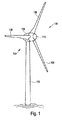
図1は、一タワー102と一ナセル104を備える一風力発電装置100を示す。ナセル104には3つのロータブレード108と一スピナ110を備える一ロータ106が配置されている。ロータ106は、運転時に風によって回転運動され、これによりナセル104内の発電機を駆動する。
FIG. 1 shows a
図2は、簡単に案内装置1と称することもできる引張ケーブルを案内するための装置の斜視図である。この案内装置1は、2つの案内支持具2と、1つの上方案内レール6および1つの下方案内レール8とから形成される支持具受け部4とを有する。この案内装置1は、支持具受け部4を介して、すなわち2つの案内レール6と8を介してタワー内壁に固定される。この状況が図2に示されており、タワー壁はここに図示されていない。しかし特に上方案内レール6と下方案内レール8は湾曲した形状であることが分かる。この湾曲した形状はこの箇所でのタワー壁の曲がり方、すなわち内径に対応する。
FIG. 2 is a perspective view of an apparatus for guiding a tension cable, which can also be referred to simply as the guiding
2つの案内レール6と8は角度が付与されて構成されており、それぞれタワー壁に固定するための壁部分10ないし12と、これに対してそれぞれほぼ直角に配置された支持具部分11ないし13とを有し、支持具部分には少なくとも1つの案内支持具が固定される。タワー壁に固定するために、および少なくとも1つの案内支持具にも固定するために、ネジの形態の固定手段14が設けられている。これらの固定手段14には簡単にするため同じ参照符号が付してある。ここで固定手段は、上方と下方の案内レール6と8の間で異なっていても良く、壁部分10ないし12の固定に対して使用される固定手段も、少なくとも1つの案内支持具を支持具部分11ないし13に固定するための固定手段とは異なっていて良い。ここで好ましくは固定手段としてそれぞれ、場合により大きさの異なるネジが提案される。これは図2にも示されている。
The two guide rails 6 and 8 are configured to be angled, each having a
そして案内支持具2を固定するために支持具部分11と13にはそれぞれ長穴16ないし18が設けられている。下方案内レール8、すなわち下方支持具部分13の長穴18はこの図では案内支持具2によって覆われており、したがって破線でのみ図示されている。
In order to fix the
2つの案内支持具2は、2つの案内レール6と8との間に、すなわち2つの支持具部分11と13との間に配置され、固定手段14によって長穴16と18に固定することができる。固定手段がまだ緩んでいる場合、案内支持具2は、すなわちそれぞれ互いに独立して、それぞれ二重矢印により示された周方向20にスライドすることができる。案内支持具2がそれぞれ所望の位置に達すると直ちに、案内支持具は対応の固定手段14により堅固に固定することができる。
The two guide supports 2 are arranged between the two guide rails 6 and 8, i.e. between the two
図3にはタワー22が上方から見た断面図に示されている。このタワー22は、その周囲にわたって分散された種々の案内支持具2を有し、それらのうち常に2つの部材が1つの案内装置1に所属する。それぞれ2つの案内支持具2は、それぞれ1つの上方と下方の案内レール6ないし8を介して互いに接続されている。これら参照符号6と8が図3に示されているが、それぞれ上方案内レール6は下方案内レール8を覆い隠している。
FIG. 3 is a sectional view of the
いずれにしろ上方と下方の案内レール6と8は、内側からタワー壁部24に固定されている。そして引張ケーブルを配置することができ、各案内支持具2の受け面26にそれぞれ当接することができる。
In any case, the upper and lower guide rails 6 and 8 are fixed to the
図4は、案内支持具2’を上方および下方の案内レール6ないし8と共に案内装置1’へと組み立てる前の状態で示す。図4により設けられた案内装置1’も、規定どおりに2つの案内支持具2’を有する。ただしここで第2の案内支持具2’は、図4には図示されていない。
FIG. 4 shows the guide support 2 'before assembly into the guide device 1' with the upper and lower guide rails 6-8. The
図4には下方案内レール8のうち、とりわけ壁部分12、および長穴18を備える支持具部分13が良く示されている。上方案内レール6のうち、2つの長穴16を備える支持具部分11が示されている。
FIG. 4 shows the lower guide rail 8 in particular the
案内支持具2’はここでは、それぞれ支持具部分11ないし13に固定されるべき本体28を有し、かつ規定どおりにタワー壁部に内側から当接する。すなわちタワー内壁に当接する。さらに本体28には調整体30が設けられており、この調整体はここでは受け面26’を形成する。この調整体30は複数の個別物体から形成することもできる。この調整体30によって案内支持具2’は比較的に大きな厚さを獲得し、これによりタワー壁部と引張ケーブルとの間に比較的に大きな間隔を達成ないし調整することができる。
The guide support 2 'here has a
かくて簡単に、特に容易に作製され、公差に適合することのできる案内装置が創出され、この案内装置は引張ケーブルをタワーの内部で案内することができる。この案内装置は、後装備するのにも同様に適する。 Thus, a guide device is created that is simple, particularly easy to make and can meet tolerances, and can guide the tension cable inside the tower. This guide device is equally suitable for later installation.
100 風力発電装置
102 タワー
104 ナセル
106 ロータ
108 ロータブレード
110 スピナ
1,1’ 案内装置
2,2’ 案内支持具
4 支持具受け部
6 上方案内レール
8 下方案内レール
10,12 壁部分
11,13 支持具部分
14 固定手段
16,18 長穴
20 周方向
22 タワー
24 タワー壁部
26,26’ 受け面
28 本体
30 調整体
DESCRIPTION OF
Claims (10)
タワー(22)内部においてタワー壁部(24)と少なくとも1つの引張ケーブルとの間に配置するための少なくとも1つの案内支持具(2)を含み、これにより該少なくとも1つの引張ケーブルは当該案内支持具(2)に当接し、これによって前記タワー壁部(24)において案内され、
さらに前記案内支持具(2)をタワー壁部(24)に固定するための支持具受け部(4)を含み、
前記案内支持具(2)の位置は、少なくとも1つの引張ケーブルの位置に適合するためにタワー(22)の周方向(20)において支持具受け部(4)に沿って変更することができるよう構成された、装置。 A device for guiding a tension cable in a tower (22) of a wind turbine generator,
Including at least one guide support (2) for disposition within the tower (22) between the tower wall (24) and the at least one tension cable, whereby the at least one tension cable has the guide support Abuts against the tool (2), thereby being guided in the tower wall (24),
And a support receiving part (4) for fixing the guide support (2) to the tower wall (24),
The position of the guide support (2) can be changed along the support receiving part (4) in the circumferential direction (20) of the tower (22) to match the position of at least one tension cable. Configured device.
当該装置は複数の案内支持具(2)を含み、
支持具受け部(4)は、当該複数の案内支持具(2)を固定するために設けられている、ことを特徴とする装置。 The apparatus according to claim 1 or 3,
The apparatus includes a plurality of guide supports (2),
Support receiving portion (4) is provided for securing the plurality of guide support (2), equipment you wherein a.
引張ケーブルは、タワー壁部(24)の外側でタワーの内部において案内され、引張ケーブルを案内するために請求項1から6のいずれか一項による少なくとも1つの装置が使用されるタワー。 A tower (22) of a wind turbine generator comprising a concrete part and held in tension from a tension cable,
A tower in which the tension cable is guided inside the tower outside the tower wall (24), and at least one device according to any one of claims 1 to 6 is used to guide the tension cable.
引張ケーブルは、タワー壁部(24)の外側でタワーの内部において案内され、引張ケーブルを案内するために請求項1から6のいずれか一項による少なくとも1つの装置が使用され、請求項7又は8によるタワー(22)が建造され、および/または請求項9による風力発電装置が建造される方法。 A method for constructing a wind turbine generator comprising a tower (22) comprising a concrete part and tensioned from a tension cable,
Pulling cable is guided inside outward at the tower of the tower wall portion (24), a tensile at least one device according to any one of claims 1 to 6, for guiding the cable is in use, according to claim 7 or Method according to claim 8, wherein a tower (22) is constructed and / or a wind power plant according to claim 9 is constructed.
Applications Claiming Priority (3)
| Application Number | Priority Date | Filing Date | Title |
|---|---|---|---|
| DE102015206668.1 | 2015-04-14 | ||
| DE102015206668.1A DE102015206668A1 (en) | 2015-04-14 | 2015-04-14 | Tension cable guide in a wind turbine tower |
| PCT/EP2016/057745 WO2016166026A1 (en) | 2015-04-14 | 2016-04-08 | Tension cord guide in a wind turbine tower |
Publications (2)
| Publication Number | Publication Date |
|---|---|
| JP2018516323A JP2018516323A (en) | 2018-06-21 |
| JP6612357B2 true JP6612357B2 (en) | 2019-11-27 |
Family
ID=55745769
Family Applications (1)
| Application Number | Title | Priority Date | Filing Date |
|---|---|---|---|
| JP2017553914A Expired - Fee Related JP6612357B2 (en) | 2015-04-14 | 2016-04-08 | Tensile cable guide in a wind turbine tower |
Country Status (14)
| Country | Link |
|---|---|
| US (1) | US10316537B2 (en) |
| EP (1) | EP3283716B1 (en) |
| JP (1) | JP6612357B2 (en) |
| CN (1) | CN107532425B (en) |
| AR (1) | AR106362A1 (en) |
| BR (1) | BR112017021989A2 (en) |
| CA (1) | CA2980972C (en) |
| DE (1) | DE102015206668A1 (en) |
| DK (1) | DK3283716T3 (en) |
| ES (1) | ES2727795T3 (en) |
| PT (1) | PT3283716T (en) |
| TW (1) | TW201700860A (en) |
| UY (1) | UY36624A (en) |
| WO (1) | WO2016166026A1 (en) |
Families Citing this family (3)
| Publication number | Priority date | Publication date | Assignee | Title |
|---|---|---|---|---|
| DE102020127750A1 (en) | 2020-10-21 | 2022-04-21 | Karl Hartinger Kranbetrieb Gmbh & Co Kg | Device and method for separating clamping elements |
| EP4119791A1 (en) * | 2021-07-15 | 2023-01-18 | Siemens Gamesa Renewable Energy A/S | Platform for a tower of a wind turbine and wind turbine |
| CN114738439B (en) * | 2022-04-13 | 2024-03-22 | 同济大学 | Vibration damper for cooling tower |
Family Cites Families (16)
| Publication number | Priority date | Publication date | Assignee | Title |
|---|---|---|---|---|
| DE3806759C2 (en) | 1988-03-02 | 1998-06-04 | Dyckerhoff & Widmann Ag | Method for renovating a hollow cylindrical building body and kit system therefor |
| DE4001577A1 (en) | 1990-01-20 | 1991-07-25 | Plica Peter | Prestressing component anchoring system - has plastics strip between saddle and loop formed in component |
| DE10126912A1 (en) | 2001-06-01 | 2002-12-19 | Oevermann Gmbh & Co Kg Hoch Un | Prestressed concrete tower structure |
| JP2006246549A (en) * | 2005-02-28 | 2006-09-14 | Mitsubishi Heavy Ind Ltd | Method of laying cable for wind energy conversion system, and cable laying device, and wind energy conversion system using it |
| DK178145B1 (en) * | 2008-03-05 | 2015-06-29 | Aip Aps | Horizontal movement restriction system in a lift |
| CN102099538B (en) * | 2008-07-15 | 2013-08-14 | 西门子公司 | Method for the assembly of a tower and tower |
| CN102164841B (en) * | 2008-08-29 | 2014-08-06 | 维斯塔斯风力系统集团公司 | Arrangement for cable guiding and a wind turbine using such arrangement |
| PL2339094T3 (en) | 2009-12-23 | 2016-12-30 | Tower having a pre-stressed concrete column and construction method | |
| JP5469519B2 (en) * | 2010-04-14 | 2014-04-16 | Thk株式会社 | Rotary actuator and horizontal axis windmill |
| US20110138704A1 (en) * | 2010-06-30 | 2011-06-16 | General Electric Company | Tower with tensioning cables |
| US8307593B2 (en) * | 2010-08-18 | 2012-11-13 | General Electric Company | Tower with adapter section |
| CN202064270U (en) | 2011-01-27 | 2011-12-07 | 同济大学 | Steering gear of adjustable prestress |
| EP2518844B1 (en) * | 2011-04-27 | 2013-11-13 | Siemens Aktiengesellschaft | Arrangement and method for installing cables |
| DK2604570T3 (en) * | 2011-12-13 | 2014-10-06 | Siemens Ag | Wiring in a wind turbine tower |
| CN104284857A (en) * | 2012-02-01 | 2015-01-14 | Vsl国际股份公司 | Heavy lifting apparatus and method |
| ES2471641B1 (en) * | 2012-12-21 | 2015-04-07 | Acciona Windpower, S.A. | Prefabricated concrete dovela, wind turbine tower comprising said dovela, wind turbine comprising said tower and assembly procedure of said wind turbine |
-
2015
- 2015-04-14 DE DE102015206668.1A patent/DE102015206668A1/en not_active Withdrawn
-
2016
- 2016-04-08 DK DK16715843.5T patent/DK3283716T3/en active
- 2016-04-08 CA CA2980972A patent/CA2980972C/en active Active
- 2016-04-08 CN CN201680021511.9A patent/CN107532425B/en not_active Expired - Fee Related
- 2016-04-08 ES ES16715843T patent/ES2727795T3/en active Active
- 2016-04-08 JP JP2017553914A patent/JP6612357B2/en not_active Expired - Fee Related
- 2016-04-08 US US15/564,717 patent/US10316537B2/en active Active
- 2016-04-08 EP EP16715843.5A patent/EP3283716B1/en active Active
- 2016-04-08 WO PCT/EP2016/057745 patent/WO2016166026A1/en active Application Filing
- 2016-04-08 BR BR112017021989-1A patent/BR112017021989A2/en not_active Application Discontinuation
- 2016-04-08 PT PT16715843T patent/PT3283716T/en unknown
- 2016-04-13 TW TW105111535A patent/TW201700860A/en unknown
- 2016-04-13 UY UY0001036624A patent/UY36624A/en not_active Application Discontinuation
- 2016-04-14 AR ARP160101000A patent/AR106362A1/en active IP Right Grant
Also Published As
| Publication number | Publication date |
|---|---|
| EP3283716B1 (en) | 2019-03-13 |
| CA2980972C (en) | 2020-03-24 |
| BR112017021989A2 (en) | 2018-07-10 |
| DE102015206668A1 (en) | 2016-10-20 |
| JP2018516323A (en) | 2018-06-21 |
| US20180106061A1 (en) | 2018-04-19 |
| UY36624A (en) | 2016-11-30 |
| US10316537B2 (en) | 2019-06-11 |
| EP3283716A1 (en) | 2018-02-21 |
| ES2727795T3 (en) | 2019-10-18 |
| CN107532425B (en) | 2019-12-24 |
| TW201700860A (en) | 2017-01-01 |
| PT3283716T (en) | 2019-06-04 |
| DK3283716T3 (en) | 2019-05-13 |
| WO2016166026A1 (en) | 2016-10-20 |
| CN107532425A (en) | 2018-01-02 |
| CA2980972A1 (en) | 2016-10-20 |
| AR106362A1 (en) | 2018-01-10 |
Similar Documents
| Publication | Publication Date | Title |
|---|---|---|
| JP6612357B2 (en) | Tensile cable guide in a wind turbine tower | |
| KR102089253B1 (en) | Fixing system for cables, in particular in wind turbines | |
| KR101428903B1 (en) | Wind power plant foundation and wind power plant | |
| JP6130381B2 (en) | Inter-pipe brace assembly | |
| US9562626B2 (en) | Bracket for tubular element, in particular for aircraft | |
| KR20130102548A (en) | Attachment system for cables, in particular for wind power installations | |
| CN102338138A (en) | Adjustable fixing device | |
| KR101020466B1 (en) | Cable duct mounting assembly | |
| CN115917201A (en) | Tension unloading piece | |
| US11846272B2 (en) | Cable holder for a cable of a wind turbine, and method | |
| KR100913815B1 (en) | A four lines power cable lead apparatus | |
| KR101997352B1 (en) | Strut with operating noise reducing | |
| JP2018061391A (en) | Connection structure | |
| KR20150035237A (en) | Electric pole installed supporting wire | |
| KR200463836Y1 (en) | Clamp for both Crops supporter and Greenhouse's Support Pipe | |
| JP3245163U (en) | Metal wheel attachment used for cable laying ducts | |
| JP6912403B2 (en) | Holding structure of the middle part of the wire and wire holding device | |
| JP2009275418A (en) | Vertical wall panel mounting structure and base fitting | |
| JP2009290964A (en) | Electric wire support | |
| KR20160106815A (en) | Clamp for form | |
| KR20200072892A (en) | Connector | |
| JP6156866B2 (en) | Rope fixture | |
| KR20160041327A (en) | Holding for a fixed platform with a cable receiving function | |
| JP2019047595A (en) | Coupling member movement prevention instrument and relaxation degree adjustment coupler having the same | |
| KR200380325Y1 (en) | electric wire support of cable tray |
Legal Events
| Date | Code | Title | Description |
|---|---|---|---|
| A521 | Request for written amendment filed |
Free format text: JAPANESE INTERMEDIATE CODE: A523 Effective date: 20171205 |
|
| A621 | Written request for application examination |
Free format text: JAPANESE INTERMEDIATE CODE: A621 Effective date: 20171205 |
|
| A977 | Report on retrieval |
Free format text: JAPANESE INTERMEDIATE CODE: A971007 Effective date: 20181029 |
|
| A131 | Notification of reasons for refusal |
Free format text: JAPANESE INTERMEDIATE CODE: A131 Effective date: 20181113 |
|
| A601 | Written request for extension of time |
Free format text: JAPANESE INTERMEDIATE CODE: A601 Effective date: 20190207 |
|
| A601 | Written request for extension of time |
Free format text: JAPANESE INTERMEDIATE CODE: A601 Effective date: 20190408 |
|
| A521 | Request for written amendment filed |
Free format text: JAPANESE INTERMEDIATE CODE: A523 Effective date: 20190510 |
|
| TRDD | Decision of grant or rejection written | ||
| A01 | Written decision to grant a patent or to grant a registration (utility model) |
Free format text: JAPANESE INTERMEDIATE CODE: A01 Effective date: 20191015 |
|
| A61 | First payment of annual fees (during grant procedure) |
Free format text: JAPANESE INTERMEDIATE CODE: A61 Effective date: 20191030 |
|
| R150 | Certificate of patent or registration of utility model |
Ref document number: 6612357 Country of ref document: JP Free format text: JAPANESE INTERMEDIATE CODE: R150 |
|
| LAPS | Cancellation because of no payment of annual fees |