JP6611360B2 - Bearing device for door - Google Patents
Bearing device for door Download PDFInfo
- Publication number
- JP6611360B2 JP6611360B2 JP2016551802A JP2016551802A JP6611360B2 JP 6611360 B2 JP6611360 B2 JP 6611360B2 JP 2016551802 A JP2016551802 A JP 2016551802A JP 2016551802 A JP2016551802 A JP 2016551802A JP 6611360 B2 JP6611360 B2 JP 6611360B2
- Authority
- JP
- Japan
- Prior art keywords
- refrigerator
- freezer
- attenuator
- door
- curved guide
- Prior art date
- Legal status (The legal status is an assumption and is not a legal conclusion. Google has not performed a legal analysis and makes no representation as to the accuracy of the status listed.)
- Expired - Fee Related
Links
Images


Classifications
-
- E—FIXED CONSTRUCTIONS
- E05—LOCKS; KEYS; WINDOW OR DOOR FITTINGS; SAFES
- E05F—DEVICES FOR MOVING WINGS INTO OPEN OR CLOSED POSITION; CHECKS FOR WINGS; WING FITTINGS NOT OTHERWISE PROVIDED FOR, CONCERNED WITH THE FUNCTIONING OF THE WING
- E05F1/00—Closers or openers for wings, not otherwise provided for in this subclass
- E05F1/08—Closers or openers for wings, not otherwise provided for in this subclass spring-actuated, e.g. for horizontally sliding wings
- E05F1/10—Closers or openers for wings, not otherwise provided for in this subclass spring-actuated, e.g. for horizontally sliding wings for swinging wings, e.g. counterbalance
- E05F1/12—Mechanisms in the shape of hinges or pivots, operated by springs
- E05F1/1246—Mechanisms in the shape of hinges or pivots, operated by springs with a coil spring perpendicular to the pivot axis
- E05F1/1253—Mechanisms in the shape of hinges or pivots, operated by springs with a coil spring perpendicular to the pivot axis with a compression spring
-
- E—FIXED CONSTRUCTIONS
- E05—LOCKS; KEYS; WINDOW OR DOOR FITTINGS; SAFES
- E05F—DEVICES FOR MOVING WINGS INTO OPEN OR CLOSED POSITION; CHECKS FOR WINGS; WING FITTINGS NOT OTHERWISE PROVIDED FOR, CONCERNED WITH THE FUNCTIONING OF THE WING
- E05F3/00—Closers or openers with braking devices, e.g. checks; Construction of pneumatic or liquid braking devices
- E05F3/04—Closers or openers with braking devices, e.g. checks; Construction of pneumatic or liquid braking devices with liquid piston brakes
- E05F3/10—Closers or openers with braking devices, e.g. checks; Construction of pneumatic or liquid braking devices with liquid piston brakes with a spring, other than a torsion spring, and a piston, the axes of which are the same or lie in the same direction
- E05F3/104—Closers or openers with braking devices, e.g. checks; Construction of pneumatic or liquid braking devices with liquid piston brakes with a spring, other than a torsion spring, and a piston, the axes of which are the same or lie in the same direction with cam-and-slide transmission between driving shaft and piston within the closer housing
-
- E—FIXED CONSTRUCTIONS
- E05—LOCKS; KEYS; WINDOW OR DOOR FITTINGS; SAFES
- E05F—DEVICES FOR MOVING WINGS INTO OPEN OR CLOSED POSITION; CHECKS FOR WINGS; WING FITTINGS NOT OTHERWISE PROVIDED FOR, CONCERNED WITH THE FUNCTIONING OF THE WING
- E05F3/00—Closers or openers with braking devices, e.g. checks; Construction of pneumatic or liquid braking devices
- E05F3/22—Additional arrangements for closers, e.g. for holding the wing in opened or other position
- E05F3/221—Mechanical power-locks, e.g. for holding the wing open or for free-moving zones
-
- E—FIXED CONSTRUCTIONS
- E05—LOCKS; KEYS; WINDOW OR DOOR FITTINGS; SAFES
- E05F—DEVICES FOR MOVING WINGS INTO OPEN OR CLOSED POSITION; CHECKS FOR WINGS; WING FITTINGS NOT OTHERWISE PROVIDED FOR, CONCERNED WITH THE FUNCTIONING OF THE WING
- E05F5/00—Braking devices, e.g. checks; Stops; Buffers
-
- E—FIXED CONSTRUCTIONS
- E05—LOCKS; KEYS; WINDOW OR DOOR FITTINGS; SAFES
- E05D—HINGES OR SUSPENSION DEVICES FOR DOORS, WINDOWS OR WINGS
- E05D7/00—Hinges or pivots of special construction
- E05D7/08—Hinges or pivots of special construction for use in suspensions comprising two spigots placed at opposite edges of the wing, especially at the top and the bottom, e.g. trunnions
- E05D7/081—Hinges or pivots of special construction for use in suspensions comprising two spigots placed at opposite edges of the wing, especially at the top and the bottom, e.g. trunnions the pivot axis of the wing being situated near one edge of the wing, especially at the top and bottom, e.g. trunnions
-
- E—FIXED CONSTRUCTIONS
- E05—LOCKS; KEYS; WINDOW OR DOOR FITTINGS; SAFES
- E05F—DEVICES FOR MOVING WINGS INTO OPEN OR CLOSED POSITION; CHECKS FOR WINGS; WING FITTINGS NOT OTHERWISE PROVIDED FOR, CONCERNED WITH THE FUNCTIONING OF THE WING
- E05F3/00—Closers or openers with braking devices, e.g. checks; Construction of pneumatic or liquid braking devices
- E05F3/22—Additional arrangements for closers, e.g. for holding the wing in opened or other position
-
- E—FIXED CONSTRUCTIONS
- E05—LOCKS; KEYS; WINDOW OR DOOR FITTINGS; SAFES
- E05Y—INDEXING SCHEME RELATING TO HINGES OR OTHER SUSPENSION DEVICES FOR DOORS, WINDOWS OR WINGS AND DEVICES FOR MOVING WINGS INTO OPEN OR CLOSED POSITION, CHECKS FOR WINGS AND WING FITTINGS NOT OTHERWISE PROVIDED FOR, CONCERNED WITH THE FUNCTIONING OF THE WING
- E05Y2201/00—Constructional elements; Accessories therefore
- E05Y2201/60—Suspension or transmission members; Accessories therefore
- E05Y2201/622—Suspension or transmission members elements
- E05Y2201/624—Arms
- E05Y2201/626—Levers
-
- E—FIXED CONSTRUCTIONS
- E05—LOCKS; KEYS; WINDOW OR DOOR FITTINGS; SAFES
- E05Y—INDEXING SCHEME RELATING TO HINGES OR OTHER SUSPENSION DEVICES FOR DOORS, WINDOWS OR WINGS AND DEVICES FOR MOVING WINGS INTO OPEN OR CLOSED POSITION, CHECKS FOR WINGS AND WING FITTINGS NOT OTHERWISE PROVIDED FOR, CONCERNED WITH THE FUNCTIONING OF THE WING
- E05Y2201/00—Constructional elements; Accessories therefore
- E05Y2201/60—Suspension or transmission members; Accessories therefore
- E05Y2201/622—Suspension or transmission members elements
- E05Y2201/628—Bearings
-
- E—FIXED CONSTRUCTIONS
- E05—LOCKS; KEYS; WINDOW OR DOOR FITTINGS; SAFES
- E05Y—INDEXING SCHEME RELATING TO HINGES OR OTHER SUSPENSION DEVICES FOR DOORS, WINDOWS OR WINGS AND DEVICES FOR MOVING WINGS INTO OPEN OR CLOSED POSITION, CHECKS FOR WINGS AND WING FITTINGS NOT OTHERWISE PROVIDED FOR, CONCERNED WITH THE FUNCTIONING OF THE WING
- E05Y2600/00—Mounting or coupling arrangements for elements provided for in this subclass
- E05Y2600/40—Mounting location; Visibility of the elements
- E05Y2600/41—Concealed
-
- E—FIXED CONSTRUCTIONS
- E05—LOCKS; KEYS; WINDOW OR DOOR FITTINGS; SAFES
- E05Y—INDEXING SCHEME RELATING TO HINGES OR OTHER SUSPENSION DEVICES FOR DOORS, WINDOWS OR WINGS AND DEVICES FOR MOVING WINGS INTO OPEN OR CLOSED POSITION, CHECKS FOR WINGS AND WING FITTINGS NOT OTHERWISE PROVIDED FOR, CONCERNED WITH THE FUNCTIONING OF THE WING
- E05Y2900/00—Application of doors, windows, wings or fittings thereof
- E05Y2900/10—Application of doors, windows, wings or fittings thereof for buildings or parts thereof
- E05Y2900/13—Application of doors, windows, wings or fittings thereof for buildings or parts thereof characterised by the type of wing
- E05Y2900/132—Doors
-
- E—FIXED CONSTRUCTIONS
- E05—LOCKS; KEYS; WINDOW OR DOOR FITTINGS; SAFES
- E05Y—INDEXING SCHEME RELATING TO HINGES OR OTHER SUSPENSION DEVICES FOR DOORS, WINDOWS OR WINGS AND DEVICES FOR MOVING WINGS INTO OPEN OR CLOSED POSITION, CHECKS FOR WINGS AND WING FITTINGS NOT OTHERWISE PROVIDED FOR, CONCERNED WITH THE FUNCTIONING OF THE WING
- E05Y2900/00—Application of doors, windows, wings or fittings thereof
- E05Y2900/30—Application of doors, windows, wings or fittings thereof for domestic appliances
- E05Y2900/31—Application of doors, windows, wings or fittings thereof for domestic appliances for refrigerators
Description
本発明は、ドアを回転可能に取り付けるためのベアリング軸と、バネの力によってドアを特定の枢動範囲にわたって閉方向に向けて動かすことができる閉鎖装置と、ドアの枢動移動を少なくとも1つの枢動範囲にわたって減衰させるための減衰器とを備えた、特に冷蔵庫のためのドア用のベアリング装置に関するものである。 The present invention includes a bearing shaft for rotatably mounting a door, a closing device capable of moving the door in a closing direction over a specific pivot range by a spring force, and at least one pivot movement of the door. The invention relates to a bearing device for a door, in particular for a refrigerator, with an attenuator for damping over a pivot range.
ドイツ実用新案公報20 2006 010 482には、冷蔵庫又は冷凍庫のドアを枢動可能に取り付けるための装置が開示されている。この具体例では、枢動可能なドアは閉鎖装置及び減衰装置を駆動するレバーに結合されている。この具体例では、閉鎖装置及び減衰装置はドアにより特定の枢動範囲にわたって動かされる枢動部材による駆動が可能となっている。枢動部材により減衰装置を閉鎖装置と堅固に固定してしまうと、ドアに対して減衰力又は閉鎖力を柔軟に加えることができなくなってしまうという欠点が生じる。加えて、比較的小さな減衰力や閉鎖力しか用いることができないという問題も生じる。
German
従って、本発明の目的は、意図した用途に減衰力及び閉鎖力を柔軟に適合させることができるドア用の閉鎖装置及び減衰器を用いたベアリング装置の提供にある。
この目的は請求項1に記載の構成要素を備えたベアリング装置によって達成される。
Accordingly, it is an object of the present invention to provide a door closing device and a bearing device using the attenuator that can flexibly adapt the damping force and closing force to the intended application.
This object is achieved by a bearing device comprising the component according to claim 1.
本発明に従って、ベアリング軸により可動な第1の湾曲状のガイドが閉鎖装置を動かすために設けられ、ベアリング軸により可動な第2の湾曲状のガイドが減衰器を動かすために設けられている。この実施形態では、これらの湾曲状のガイドは、夫々、閉鎖装置及び/又は減衰器に作用する制御用突出部を有することができる。この実施形態では、閉鎖装置と減衰器とに対して夫々別個の湾曲状のガイドを用いることができるようになっているが、閉鎖装置及び湾曲状のガイドの両方に作用する単一の湾曲状のガイドを提供するようにしてもよい。
これらの湾曲状のガイドを用いることにより、もはやドアと閉鎖装置との間及びドアと減衰器との間が堅固に結合されなくなるので閉鎖力又は減衰力をより正確に設定することができるようになる。もっと正確にいえば、結合はこれらの湾曲状のガイドを介して形成され、これらの湾曲状のガイドはドアの枢動時に閉鎖装置と減衰器とに作用するようになっている。この実施形態では、閉鎖装置及び減衰器にはバネによって湾曲状のガイドに抗するテンションが予め掛けられるようになっていてもよい。
In accordance with the present invention, a first curved guide movable by the bearing shaft is provided for moving the closure device, and a second curved guide movable by the bearing shaft is provided for moving the attenuator. In this embodiment, these curved guides can each have a control projection that acts on the closure device and / or the attenuator. In this embodiment, separate curved guides can be used for the closure device and the attenuator, but a single curved shape acting on both the closure device and the curved guide. A guide may be provided.
By using these curved guides, the closing force or damping force can be set more accurately since there is no longer a strong connection between the door and the closing device and between the door and the attenuator. Become. More precisely, the coupling is formed through these curved guides, which act on the closing device and the attenuator when the door is pivoted. In this embodiment, the closing device and the attenuator may be pre-tensioned against the curved guide by a spring.
第1の湾曲状のガイド及び第2の湾曲状のガイドが回転不能にベアリング軸に接続されるのが好ましく、極めてコンパクトな構造が可能となる。この実施形態では、第1の湾曲状のガイド及び第2の湾曲状のガイドは、軸方向に沿って互いにオフセットされて配置されてもよいし、又は、その上に制御用突出部が形成される単一の円板によって形成されてもよい。 The first curved guide and the second curved guide are preferably non-rotatably connected to the bearing shaft, allowing a very compact structure. In this embodiment, the first curved guide and the second curved guide may be arranged offset from each other along the axial direction, or a control protrusion is formed thereon. May be formed by a single disk.
1つの好ましい実施形態によれば、第2の湾曲状のガイドは、減衰器を駆動し、ドアを閉位置に到着する前に閉方向にまた最大開位置に到達する前に開方向に減衰させるようになっている。従って、閉方向の減衰及び開方向の減衰を提供するために単一の減衰器を用いることができるようになっている。減衰器は第2の制御用湾曲部の対応する制御用突出部により駆動されるようになっている。開方向の減衰は最大開位置に到着する前に生じ、たとえば90°と180°との間の範囲にありうる。この実施形態では、開方向の減衰及び閉方向の減衰は、夫々、少なくとも5°というドアの枢動範囲にわたるものであり、好ましくは、閉方向の減衰が閉位置前の10°と50°との間にわたり、開方向の減衰が最大開位置前の5°と25°の間にわたる。 According to one preferred embodiment, the second curved guide drives the attenuator and damps the door in the closing direction before reaching the closed position and in the opening direction before reaching the maximum open position. It is like that. Thus, a single attenuator can be used to provide close and open damping. The attenuator is driven by the corresponding control protrusion of the second control bend. Attenuation in the open direction occurs before reaching the maximum open position, and can range, for example, between 90 ° and 180 °. In this embodiment, the damping in the opening direction and the damping in the closing direction each span a door pivot range of at least 5 °, and preferably the closing direction damping is 10 ° and 50 ° before the closed position. In between, the attenuation in the open direction ranges between 5 ° and 25 ° before the maximum open position.
コンパクトな構造の場合、閉鎖装置及び減衰器をハウジング内に収容し、このハウジングを冷蔵庫の中に又は外に取り付けることができる。
好ましくは、減衰器は、伸張時よりも圧縮時の方が高い減衰力を生じる線形圧縮式減衰器として設計される。従って、減衰器は、閉方向減衰時又は開方向減衰時に高制動力を提供することができるが、反対方向の動きの間、ユーザは減衰器の存在をわずかしか又は全く気づくことはない。圧縮式減衰器に代えて牽引式減衰器が用いられてもよいし又は回転式減衰器が用いられてもよい。
In the case of a compact construction, the closure device and the attenuator can be housed in a housing, which can be mounted in or outside the refrigerator.
Preferably, the attenuator is designed as a linear compression attenuator that produces a higher damping force when compressed than when stretched. Thus, the attenuator can provide a high braking force when closed or open, but the user is unaware of the presence of the attenuator during movement in the opposite direction. A traction attenuator may be used instead of the compression attenuator, or a rotary attenuator may be used.
好ましくは、減衰器は、ハウジングの片側に回転可能に取り付けられ、他方側ではピボット部材に回転可能に保持される。この実施形態では、第2の湾曲状のガイドは制御用突出部を有している。制御用突出部はピボット部材及び/又はピボット部材に配置されたローラに作用してドアの開閉時に減衰器を駆動させるようになっている。
好ましくは、閉鎖装置は圧縮バネを有している。圧縮バネは2つの末端部材間に張架されている。この実施形態では、一方の末端部材はハウジングに回転可能に取り付けられ、また、他方の末端部材は、回転可能に取り付けられた駆動部材に取り付けられている。次いで、回転可能に取り付けられた駆動部材は、第1の湾曲状のガイドの少なくとも1つの制御用突出部によって動かすことができるようになっている。少なくとも1つの制御用突出部が作用する回転可能に取り付けられた駆動部材には回転可能なローラを設けることもできる。
Preferably, the attenuator is rotatably mounted on one side of the housing and is rotatably held on the pivot member on the other side. In this embodiment, the second curved guide has a control protrusion. The control protrusion acts on the pivot member and / or a roller disposed on the pivot member to drive the attenuator when the door is opened and closed.
Preferably, the closure device has a compression spring. The compression spring is stretched between the two end members. In this embodiment, one end member is rotatably attached to the housing, and the other end member is attached to a rotatably attached drive member. The rotatably mounted drive member can then be moved by at least one control projection of the first curved guide. A rotatable roller can also be provided on the rotatably mounted drive member on which the at least one control projection acts.
この実施形態では、減衰器を駆動させるためのピボット部材から閉鎖装置を動かすための回転可能な駆動部材を独立させて回転させることができ、好ましくは、ピボット部材及び回転可能な駆動部材はハウジングに同一の軸を中心として回転可能なように取り付けられるようになっている。
さらに、ドアが開いてテンションの掛かった状態で閉鎖装置を歯止めするためのキャッチ機構が設けられることが好ましい。従って、閉鎖装置にテンションが掛かった後、ドアが当該閉鎖装置に起因する摩擦力又は制動力からの作用を受けることなく自由に運動することが可能となる。この実施形態では、キャッチ機構は制御用湾曲部によって動かすことができるキャッチ爪を有することができる。このキャッチ爪は、歯止めを解除する位置に向けたテンションがバネによって予め掛けられていることが好ましい。このことにより、ドアがブロック爪によって誤ってブロックされてしまうのが防止される。加えて、このキャッチ機構はコンパクトな構造を可能とする。というのは、閉鎖装置がドアの枢動経路の一部にわたってのみ動くようになっているため、この可動範囲を考慮した構造空間のみを提供するだけでよいからである。
In this embodiment, the rotatable drive member for moving the closure device can be rotated independently from the pivot member for driving the attenuator, preferably the pivot member and the rotatable drive member are attached to the housing. It is attached so as to be rotatable about the same axis.
Furthermore, it is preferable that a catch mechanism is provided for pawling the closing device in a state where the door is open and tensioned. Therefore, after tension is applied to the closing device, the door can freely move without being affected by frictional force or braking force caused by the closing device. In this embodiment, the catch mechanism can have a catch pawl that can be moved by the control bend. It is preferable that the catch claw is preliminarily tensioned by a spring toward a position where the pawl is released. This prevents the door from being accidentally blocked by the block pawl. In addition, this catch mechanism allows a compact structure. This is because the closure device can only move over a part of the door's pivot path, so that it only needs to provide a structural space that allows for this range of motion.
閉鎖装置の力と減衰器の力は、ベアリング軸の回転軸に対して実質的に直角な面内において極めて良好に働く。従って、設置状態では、ベアリング軸が実質的に鉛直方向に延び、減衰器の力及び閉鎖装置の力が実質的に水平方向に働くようになっているのが好ましい。その結果、とくに平坦な構造を有するベアリング装置が得られることになる。
本発明にかかるベアリング装置は、とくに家庭用電気機器、たとえば冷蔵庫又は冷凍庫に用いることができる。もちろんそれに加え、家具又は他の家庭用器具のための使用もさらに可能である。
The closing device force and the attenuator force work very well in a plane substantially perpendicular to the axis of rotation of the bearing shaft. Thus, in the installed state, the bearing shaft preferably extends substantially vertically so that the attenuator force and the closure device force act substantially horizontally. As a result, a bearing device having a particularly flat structure is obtained.
The bearing device according to the present invention can be used particularly for household electric appliances such as a refrigerator or a freezer. Of course, in addition, the use for furniture or other household appliances is also possible.
以下で、添付の図面を参照しながら例示的な実施形態に基づいて本発明をさらに詳細に説明する。
冷蔵庫1は、キャビネット3と、キャビネット3に回転可能に取り付けられるドア2とを備える。この目的のために、本発明にかかるベアリング装置を有するハウジング5がキャビネット3の上側に固定される。この実施形態では、ベアリング装置がベアリング軸4を有し、ベアリング軸4がハウジング内に回転可能に取り付けられ、ドア2がベアリング軸4に固定され、ドア2が回転可能となっている。図1では、ベアリング装置を有するハウジング5がキャビネット3の上側に固定されるようになっている、ベアリング装置をハウジング5とともにキャビネット3の下側に設けるようにしてもよい。他の実施形態では、ベアリング装置がキャビネット3の内部に配置されるようになっていてもよい。ただ、外部に取り付ける方が、既存の冷蔵庫への後付けが可能であるという長所を有している。
The refrigerator 1 includes a
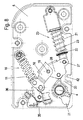
図2には、閉鎖装置10と減衰器20とが視認可能となるように、ベアリング装置を有するハウジング5がハウジングのカバーを取り除いた状態で示されている。
閉鎖装置10はバネ11を有している。バネ11は圧縮バネとして設計されている。バネ11は2つの末端部材12、13の間に張架されている。この実施形態では、第1の末端部材12が軸16を中心として回転可能となるようにハウジング5に取り付けられている。その反対側には、末端部材13が回転可能な駆動部材18の軸17の近傍に取り付けられている。回転可能な駆動部材18は、軸19を中心として回転可能となるようにハウジング5に取り付けられている。2つの末端部材12、13の間の長さの調節を行うことができるように、この場合、バネ11はスリーブ14の回りを案内され、スリーブ14はロッド15上に押圧される。
In FIG. 2, the
The closing
さらにハウジング5内には減衰器20が設けられている。減衰器20はハウジング21とピストンロッド22とを有する線形圧縮式減衰器として形成されている。この実施形態では、ピストンロッド22はハウジング21の中に挿入可能となっている。ピストンロッド22の挿入時、それに対応するピストンを通じて高い減衰力が提供される。一方、ピストンロッド22の引き出しは滑らかに行われる。この実施形態では、ハウジング21はホルダ24に固定されている。ホルダ24は軸25を中心として回転可能となるようにハウジング5に取り付けられている。その反対側では、ピストンロッド22はホルダ26を介してピボット部材28に接続されている。ホルダ26は軸27を中心として回転可能となるようにピボット部材28に取り付けられている。この実施形態では、ピボット部材28は軸19を中心として回転可能となるようにハウジング5に取り付けられている。ハウジング5には回転可能な駆動部材18も取り付けられている。回転可能な駆動部材18とピボット部材28とは軸19を中心として互いに独立して回転することができるようになっている。
Furthermore, an
閉鎖装置10及び減衰器20を駆動するために、湾曲状のガイド30が設けられている。湾曲状のガイド30はベアリング軸4に回転不能に配置されている。湾曲状のガイド30は、複数の制御用突出部31、32、33を有している。複数の制御用突出部31、32、33は回転可能な駆動部材18及びピボット部材28に作用するようになっている。この目的のために、ローラ40が回転可能な駆動部材18に回転可能に取り付けられ、ローラ41がピボット部材28に回転可能に保持されている。それに代えて、これらのローラが摺動部材に変更されてもよい。その結果、制御用突出部と回転可能な駆動部材、すなわちピボット部材28との間で連続して生じる動作摩擦をできるだけ低く抑えることが可能となる。
In order to drive the
さらに、閉鎖装置10をテンションの掛かった位置で歯止めするためのキャッチ機構がハウジング5内に設けられてもよい。当該キャッチ機構は、枢動可能なキャッチ爪35を有している。当該枢動可能なキャッチ爪35はハウジング5に軸38を中心として回転可能に取り付けられている。
Furthermore, a catch mechanism for pawling the closing
図3に示されているように閉位置からドア2が開かれる場合、ベアリング軸4が湾曲状のガイド30を左回りに回転させるので、第1の制御用突出部31はローラ40に作用して閉鎖装置10のバネ11にテンションを掛ける。それと同時に、減衰器20が閉位置と20°〜60°の開角度との間の枢動範囲でリリースされる。制御用突出部31が回転することにより、ピボット部材28は、当該ピボット部材28がハウジングの停止部42と接触するまで軸19を中心として右回りに回転する。この実施形態では、ハウジング21からのピストンロッド22の引き抜き及びそれにリンクされているピボット部材28の回転は、ホルダ26とホルダ24との間に配置されているバネ23の力によって生じるようになっている。
When the door 2 is opened from the closed position as shown in FIG. 3, the bearing
図4では、ドア2は約50°の角度位置で閉位置から離れた位置に置かれている。閉鎖装置10にさらなるテンションが掛けられる時、最初、ホルダ24とホルダ26との間の減衰器20はその位置を変えない。というのは、制御用突出部31がローラ40に作用するとともに回転可能な駆動部材18をさらに右回りに回転させ、閉鎖装置10のバネ11を圧縮するからである。
In FIG. 4, the door 2 is placed at a position away from the closed position at an angular position of about 50 °. When further tension is applied to the
ドアが35°の開角度(図3)と50°の開角度(図4)との間に開かれると、キャッチ機構の制御用湾曲部34は、キャッチ爪35の腕部37とさらに係合するので、腕部37は軸38を中心として回転する。従って、ほぼV字形に形成されているキャッチ爪35の第2の腕部36は回転可能な駆動部材18に対して枢動する。制御用湾曲部34はバネ39の力に抗してキャッチ爪35を回転させる。この実施形態では、バネ39はロック解除位置に向けたテンションをキャッチ爪35に予め掛けるようになっている。
When the door is opened between an opening angle of 35 ° (FIG. 3) and an opening angle of 50 ° (FIG. 4), the control mechanism curved
次に、ドア2が開方向に向けてさらに枢動すると、ドア2は図5に記載の位置を通り過ぎる。図5に記載の位置では、腕部36は末端部材13と係合して閉鎖装置10を歯止めする。次に、制御用湾曲部34が腕部37から移動する。歯止めがなされるとバネ11がわずかにリラックスして腕部36をしっかりと掴むように制御用突出部31が形成されているので、ローラ40は制御用突出部31から離脱することができる。
Next, when the door 2 further pivots in the opening direction, the door 2 passes the position shown in FIG. In the position illustrated in FIG. 5, the
次に、ドア2が開方向に向けて、たとえば約100°の開角度(図6)までさらに開かれると、ドア2は自由に動くことができるようになる。すなわち閉鎖装置10及び減衰器20のいずれもドア2に対して閉方向の力を加えることもなければも開方向の力を加えることもなくなる。というのは、キャッチ爪35により閉鎖装置10が歯止めされて静止した状態のままであり、減衰器20が停止部42に押し当てられて静止した状態のままになっているからである。
Next, when the door 2 is further opened in the opening direction, for example, to an opening angle of about 100 ° (FIG. 6), the door 2 can move freely. That is, neither the
次いで、ドア2が開方向に向けてさらに開かれると、湾曲状のガイド30のさらなる制御用突出部33がピボット部材28及び/又はローラ41と係合してピボット部材28を左回りに回転させる。従って、減衰器20が圧縮され、ピストンロッド22がハウジング21の中へと移動し、それにより、減衰力が生じることになる。従って、約155°の開角度(図7)から約180°の最大開位置(図8)までの開時、減衰器20は圧縮されることになる。閉鎖装置10は、依然として歯止め位置にあるので、ドア2に対して力を及ぼさない。開角度はせいぜい90°〜180°である。
Next, when the door 2 is further opened in the opening direction, the
次いで、ドア2が図8に記載の最大の開位置から閉方向に向けて閉められると、まず、減衰器20が圧縮位置から再移動する。この再移動はバネ23によって行なわれるので、ドア2の閉時に減衰器20の伸張によるいかなる力もユーザは感じることはない、次いで、約60°〜70°の開角度において制御用突出部31が回転可能な駆動部材18のローラ40と接触するようになり、それと同時に、制御用湾曲部34がキャッチ爪35の腕部37に当接するまで、ドア2が閉方向に向けてさらに閉じられる。閉鎖装置10のバネ11のわずかな圧縮及び制御用湾曲部34によるキャッチ爪35の枢動により、バネ39の力によってキャッチ爪35が軸38を中心として枢動されるため、キャッチ爪が非ロック位置へと移動可能となる。
Next, when the door 2 is closed in the closing direction from the maximum open position shown in FIG. 8, first, the
次いで、ドア2が閉方向に向けてさらに閉められ、20°と60°との間の閉角度にある場合、制御用突出部31は、ローラ41と係合してピボット部材28を左回りに枢動することにより減衰器20を圧縮位置へ移動させる。従って、ドア2の閉時に減衰力が生じる。それと同時に、閉鎖装置10は制御用湾曲部34によってロックが解除されて駆動状態となるので、バネ11は次に回転可能な駆動部材18を軸19を中心として左回りに回転させる。ローラ40は制御用突出部の裏側を動く。
Next, when the door 2 is further closed in the closing direction and is at a closing angle between 20 ° and 60 °, the
図示されているベアリング装置を用いて起こりうることであるが、製造公差に起因してドア2が0°の角度を超えて閉じられる場合、最大閉力を小さいままに留めるため、さらなる制御用突出部32が制御用湾曲部に設けられている。
図示されている例示的実施形態では、閉鎖装置10の回転可能な駆動部材18及び減衰器20のピボット部材28を同一の制御用突出部31によって部分的に駆動するようになっている。この場合、制御用突出部31は共有の制御用湾曲部として機能する。もちろん、2つの別個の制御用湾曲部をベアリング軸4に設けることも可能である。その場合、1つの制御用湾曲部は回転可能な駆動部材18に対してもっぱら作用し、第2の制御用湾曲部はピボット部材28に対してもっぱら作用するようになっている。さらに、回転可能な駆動部材18及びピボット部材28が共有の軸19を介して取り付けられるようになっていなくともよい。また、これらの部材の各々は別個の軸を有していてもよい。
As may occur with the bearing device shown, if the door 2 is closed beyond an angle of 0 ° due to manufacturing tolerances, a further control protrusion is provided to keep the maximum closing force small. The
In the exemplary embodiment shown, the
制御用突出部31、32、33の形状は夫々の意図する用途に合わせて変更されてもよい。たとえば、20°と30°との間の開角度の範囲よりも最大閉位置に到着する直前の角度範囲において減衰力がより大きくなるようにすることが可能である。加えて、湾曲状のガイド30により、閉鎖装置10のバネ11を閉位置において閉力を小さく維持してシールに対する力を小さく維持し、わずかに開いた範囲において閉力をより大きなものとするように駆動させるようにすることもできる。本発明の実施形態によっては、ベアリング軸4を別体のベアリング軸とする場合もある。すなわち、設置時にたとえばベアリング軸をドアに取り付け、このベアリング軸にベアリング装置を取り付け、次いで、ベアリング軸を湾曲状のガイドに間接的に接続するようにしてもよい。
The shape of the
図9では、ハウジング5を備えたベアリング装置がキャビネット3の上側に取り付けられ、ベアリング軸4が下方に向けて延び、ドアが非円形断面を有するベアリング軸4に取り付け可能となっている。ドアはベアリング装置から減衰力、開力及び閉力を受けるようになっている。
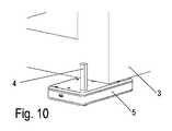
さらに、図10に示されているように、ベアリング装置がキャビネットの下側に取り付けられ、次いで、ドアが上方に向けて突出するベアリング軸4に取り付けられる。
図示されたベアリング装置は、特別な右側部品又は左側部品を必要とすることなく、キャビネット3の右側又は左側で用いられるようになっていてもよい。
In FIG. 9, the bearing device including the
Further, as shown in FIG. 10, the bearing device is attached to the lower side of the cabinet, and then the door is attached to the bearing
The illustrated bearing device may be adapted for use on the right or left side of the
1 冷蔵庫
2 ドア
3 キャビネット
4 ベアリング軸
5 ハウジング
10 閉鎖装置
11 バネ
12 末端部材
13 末端部材
14 スリーブ
15 ロッド
16 軸
17 軸
18 駆動部材
19 軸
20 減衰器
21 ハウジング
22 ピストンロッド
23 バネ
24 ホルダ
25 軸
26 ホルダ
27 軸
28 ピボット部材
30 湾曲状のガイド
31 制御用突出部
32 制御用突出部
33 制御用突出部
34 制御用湾曲部
35 キャッチ爪
36 腕部
37 腕部
38 軸
39 バネ
40 ローラ
41 ローラ
42 停止部
1 refrigerator 2
Claims (11)
前記ドア(2)を回転可能に取り付けるためのベアリング軸(4)と、
力蓄積器(11)の力によって前記ドア(2)を特定の枢動範囲にわたって閉方向に向けて動かすことができる閉鎖装置(10)と、
前記ドア(2)の枢動移動を少なくとも1つの枢動範囲にわたって減衰させるための減衰器(20)とを備えてなる冷蔵庫又は冷凍庫(1)において、
前記閉鎖装置(10)及び前記減衰器(20)が前記ベアリング軸(4)の回転軸に対して実質的に直角な面に配置されており、湾曲状のガイド(30)が間接的又は直接的に前記ベアリング軸(4)に配置されており、前記ベアリング軸(4)により可動な湾曲状のガイド(30)が前記閉鎖装置(10)を動かすために設けられており、該湾曲状のガイド(30)は前記ベアリング軸(4)により前記減衰器(20)を動かすためにも設けられてなり、
前記湾曲状のガイド(30)は制御用突出部(31,33)を備え、前記湾曲状のガイド(30)の制御用突出部(31,33)が前記ドア(2)を閉位置に到着する前に閉方向に、及び最大開位置に到着する前に開方向に減衰するように前記減衰器(20)を駆動するように構成されてなり、
前記ドア(2)が開けられたときに前記閉鎖装置(10)をテンションが掛かった状態で歯止めするためのキャッチ機構が更に設けられ、
前記キャッチ機構は、前記湾曲状のガイド(30)から突出した突出部である制御用湾曲部(34)により駆動可能なキャッチ爪(35)を有し、
前記キャッチ爪(35)が、前記歯止めを解除する位置向きのテンションがバネ(39)により予め掛けられているように構成されてなることを特徴とする、冷蔵庫又は冷凍庫(1)。 A refrigerator or freezer (1) with at least one rotatable door (2) held in a cabinet (3) by at least one bearing device, the at least one bearing device comprising :
A bearing shaft (4) for rotatably mounting the door (2);
A closing device (10) capable of moving the door (2) in a closing direction over a specific pivot range by the force of a force accumulator (11);
In a refrigerator or freezer (1) comprising an attenuator (20) for attenuating the pivoting movement of the door (2) over at least one pivoting range,
The closure device (10) and the attenuator (20) are arranged in a plane substantially perpendicular to the axis of rotation of the bearing shaft (4), and the curved guide (30) is indirectly or directly. In particular, a curved guide (30), which is arranged on the bearing shaft (4) and is movable by the bearing shaft (4), is provided for moving the closure device (10) . A guide (30) is also provided for moving the attenuator (20) by the bearing shaft (4),
The curved guide (30) includes a control protrusion (31, 33), and the control protrusion (31, 33) of the curved guide (30) arrives at the door (2) in the closed position. And configured to drive the attenuator (20) to attenuate in the closing direction before arriving and in the opening direction before reaching the maximum open position;
A catch mechanism is further provided for pawling the closure device (10) in tension when the door (2) is opened ;
The catch mechanism has a catch claw (35) that can be driven by a control bending portion (34) that is a protrusion protruding from the curved guide (30) ,
The refrigerator or freezer (1), wherein the catch claw (35) is configured so that a tension in a position for releasing the pawl is applied in advance by a spring (39 ).
Applications Claiming Priority (3)
| Application Number | Priority Date | Filing Date | Title |
|---|---|---|---|
| DE102014101849.4 | 2014-02-13 | ||
| DE102014101849.4A DE102014101849A1 (en) | 2014-02-13 | 2014-02-13 | Bearing arrangement for a door |
| PCT/EP2015/052808 WO2015121271A1 (en) | 2014-02-13 | 2015-02-11 | Bearing arrangement for a door |
Publications (2)
| Publication Number | Publication Date |
|---|---|
| JP2017511848A JP2017511848A (en) | 2017-04-27 |
| JP6611360B2 true JP6611360B2 (en) | 2019-11-27 |
Family
ID=52469837
Family Applications (1)
| Application Number | Title | Priority Date | Filing Date |
|---|---|---|---|
| JP2016551802A Expired - Fee Related JP6611360B2 (en) | 2014-02-13 | 2015-02-11 | Bearing device for door |
Country Status (11)
| Country | Link |
|---|---|
| US (1) | US9903146B2 (en) |
| EP (1) | EP3105396B1 (en) |
| JP (1) | JP6611360B2 (en) |
| KR (1) | KR102251484B1 (en) |
| CN (1) | CN105960500B (en) |
| AU (1) | AU2015217669B2 (en) |
| DE (1) | DE102014101849A1 (en) |
| ES (1) | ES2779067T3 (en) |
| PL (1) | PL3105396T3 (en) |
| RU (1) | RU2674189C2 (en) |
| WO (1) | WO2015121271A1 (en) |
Families Citing this family (8)
| Publication number | Priority date | Publication date | Assignee | Title |
|---|---|---|---|---|
| CN206666870U (en) * | 2016-12-30 | 2017-11-24 | 青岛海尔洗衣机有限公司 | A kind of damper and its washing machine |
| DE102017126366A1 (en) * | 2017-11-10 | 2019-05-16 | Hettich-Oni Gmbh & Co. Kg | Flap fitting for a furniture, side wall of a furniture body and furniture with a side wall |
| DE102017126367A1 (en) * | 2017-11-10 | 2019-05-16 | Hettich-Oni Gmbh & Co. Kg | Flap fitting for a furniture, side wall of a furniture body and furniture with a side wall |
| CN108061423B (en) * | 2017-12-30 | 2020-10-30 | 青岛海尔股份有限公司 | Door body hinge mechanism and refrigerator with same |
| CN108193966B (en) * | 2017-12-30 | 2021-03-23 | 海尔智家股份有限公司 | Door body hinge mechanism and refrigerator with same |
| EP3850178B1 (en) * | 2018-09-14 | 2022-11-23 | C.M.I. Cerniere Meccaniche Industriali S.r.L. | Hinged device for appliances and furnishings with end speed damping |
| CN111140114B (en) * | 2020-03-10 | 2021-05-14 | 长虹美菱股份有限公司 | Refrigerator hinge assembly |
| US11536070B2 (en) * | 2020-06-04 | 2022-12-27 | Whirlpool Corporation | Dish treating appliance with a door opener |
Family Cites Families (20)
| Publication number | Priority date | Publication date | Assignee | Title |
|---|---|---|---|---|
| GB408782A (en) * | 1933-02-15 | 1934-04-19 | Newman William & Sons Ltd | Improvements in door closing and checking appliances |
| US2603818A (en) * | 1948-04-12 | 1952-07-22 | George W Houlsby Jr | Door check mechanism |
| GB925095A (en) * | 1960-09-02 | 1963-05-01 | Ver Baubeschlag Gretsch Co | Improvements in or relating to door closing and checking devices |
| GB1050496A (en) * | 1963-12-24 | 1900-01-01 | ||
| DE1807399A1 (en) * | 1968-11-07 | 1970-05-27 | Doerken & Mankel Kg | Automatic door closer |
| FR2045128A5 (en) * | 1969-06-04 | 1971-02-26 | Verrieres Appliq Et | |
| DE2010580A1 (en) | 1970-03-06 | 1971-09-16 | Vereinigte Baubeschlagfabriken Gretsch & Co Gmbh, 7250 Leonberg | Door closer |
| US3773311A (en) * | 1971-09-27 | 1973-11-20 | Hartwell Corp | Overhead door control device |
| GB1344945A (en) * | 1972-01-06 | 1974-01-23 | Gibbons Ld James | Doorclosing mechanism |
| DE2522410A1 (en) * | 1975-05-21 | 1977-01-20 | Ver Baubeschlag Gretsch Co | FLOOR DOOR CLOSER |
| DE2620386C3 (en) * | 1976-05-08 | 1980-08-28 | Vereinigte Baubeschlagfabriken Gretsch & Co Gmbh, 7250 Leonberg | Hold-open device for a door closer |
| DE2608671A1 (en) * | 1976-03-03 | 1977-09-08 | Dorma Baubeschlag | AUTOMATIC DOOR CLOSER |
| JP4076528B2 (en) * | 2004-08-30 | 2008-04-16 | 日立アプライアンス株式会社 | Refrigerator door closing device |
| CN101093131B (en) * | 2006-06-21 | 2010-12-29 | 海尔集团公司 | Refrigerator |
| DE202006010482U1 (en) | 2006-07-06 | 2007-11-08 | Liebherr-Hausgeräte Lienz Gmbh | Arrangement for the pivotable mounting of a door or flap as well as refrigerators and / or freezers with such an arrangement |
| DE202007005957U1 (en) * | 2007-02-19 | 2008-06-26 | Liebherr-Hausgeräte Ochsenhausen GmbH | Fridge and / or freezer |
| DE102007036746A1 (en) * | 2007-08-03 | 2009-02-05 | Dorma Gmbh + Co. Kg | Door operating device for actuating the door of a refrigerator / freezer |
| DE102009034742A1 (en) * | 2009-07-24 | 2011-02-03 | Dorma Gmbh + Co. Kg | door closers |
| GB2479145A (en) * | 2010-03-29 | 2011-10-05 | Ingersoll Rand Security Technologies Ltd | Door closer having two springs |
| WO2015111026A1 (en) * | 2014-01-27 | 2015-07-30 | In & Tec S.R.L. | Low-bulkiness hinge |
-
2014
- 2014-02-13 DE DE102014101849.4A patent/DE102014101849A1/en not_active Withdrawn
-
2015
- 2015-02-11 JP JP2016551802A patent/JP6611360B2/en not_active Expired - Fee Related
- 2015-02-11 AU AU2015217669A patent/AU2015217669B2/en not_active Ceased
- 2015-02-11 RU RU2016133848A patent/RU2674189C2/en active
- 2015-02-11 WO PCT/EP2015/052808 patent/WO2015121271A1/en active Application Filing
- 2015-02-11 PL PL15704295T patent/PL3105396T3/en unknown
- 2015-02-11 CN CN201580007420.5A patent/CN105960500B/en active Active
- 2015-02-11 ES ES15704295T patent/ES2779067T3/en active Active
- 2015-02-11 KR KR1020167022852A patent/KR102251484B1/en active IP Right Grant
- 2015-02-11 US US15/118,317 patent/US9903146B2/en active Active
- 2015-02-11 EP EP15704295.3A patent/EP3105396B1/en active Active
Also Published As
| Publication number | Publication date |
|---|---|
| US20170175429A1 (en) | 2017-06-22 |
| RU2016133848A3 (en) | 2018-08-23 |
| US9903146B2 (en) | 2018-02-27 |
| CN105960500A (en) | 2016-09-21 |
| CN105960500B (en) | 2018-05-01 |
| EP3105396B1 (en) | 2019-12-18 |
| WO2015121271A1 (en) | 2015-08-20 |
| DE102014101849A1 (en) | 2015-08-13 |
| JP2017511848A (en) | 2017-04-27 |
| ES2779067T3 (en) | 2020-08-13 |
| AU2015217669A1 (en) | 2016-07-28 |
| KR20160124114A (en) | 2016-10-26 |
| RU2674189C2 (en) | 2018-12-05 |
| EP3105396A1 (en) | 2016-12-21 |
| AU2015217669B2 (en) | 2019-01-03 |
| PL3105396T3 (en) | 2020-06-01 |
| KR102251484B1 (en) | 2021-05-12 |
| RU2016133848A (en) | 2018-03-16 |
Similar Documents
| Publication | Publication Date | Title |
|---|---|---|
| JP6611360B2 (en) | Bearing device for door | |
| RU2673995C2 (en) | Hinge | |
| JP6295246B2 (en) | Sliding door fixture | |
| JP5572861B2 (en) | Multi-link hinge | |
| KR101803366B1 (en) | Domestic appliance | |
| US9759002B2 (en) | Pull-closed device for a movably mounted furniture part | |
| KR102569910B1 (en) | door opener | |
| JP2016518176A (en) | Drive unit for movable furniture | |
| JP2016518176A5 (en) | ||
| JP6416583B2 (en) | Locking device and joinery | |
| JP5845512B2 (en) | Automatic pull-in / damping device | |
| TW201311991A (en) | Hinge | |
| US20200131818A1 (en) | Flap fitting and item of furniture | |
| KR200479683Y1 (en) | Locking device for early open and shut function having sliding door | |
| US2679427A (en) | Latch mechanism | |
| AU2015261476B2 (en) | Hinge for furniture or domestic appliances | |
| US10641027B2 (en) | Door hinge | |
| JP4249199B2 (en) | Door self-closing device | |
| JP6516198B2 (en) | Door closing brake | |
| JP3874404B2 (en) | Door open / close control device | |
| JP6677577B2 (en) | Braking equipment, automatic moving equipment and fittings | |
| JP6594828B2 (en) | Braking device, automatic moving device and joinery | |
| JP2011153458A (en) | Finger pinching prevention device of door | |
| KR20140019963A (en) | Handle locking device for special door |
Legal Events
| Date | Code | Title | Description |
|---|---|---|---|
| A621 | Written request for application examination |
Free format text: JAPANESE INTERMEDIATE CODE: A621 Effective date: 20171117 |
|
| A977 | Report on retrieval |
Free format text: JAPANESE INTERMEDIATE CODE: A971007 Effective date: 20180919 |
|
| A131 | Notification of reasons for refusal |
Free format text: JAPANESE INTERMEDIATE CODE: A131 Effective date: 20180925 |
|
| A521 | Request for written amendment filed |
Free format text: JAPANESE INTERMEDIATE CODE: A523 Effective date: 20181221 |
|
| A131 | Notification of reasons for refusal |
Free format text: JAPANESE INTERMEDIATE CODE: A131 Effective date: 20190514 |
|
| A521 | Request for written amendment filed |
Free format text: JAPANESE INTERMEDIATE CODE: A523 Effective date: 20190711 |
|
| TRDD | Decision of grant or rejection written | ||
| A01 | Written decision to grant a patent or to grant a registration (utility model) |
Free format text: JAPANESE INTERMEDIATE CODE: A01 Effective date: 20191023 |
|
| A61 | First payment of annual fees (during grant procedure) |
Free format text: JAPANESE INTERMEDIATE CODE: A61 Effective date: 20191028 |
|
| R150 | Certificate of patent or registration of utility model |
Ref document number: 6611360 Country of ref document: JP Free format text: JAPANESE INTERMEDIATE CODE: R150 |
|
| LAPS | Cancellation because of no payment of annual fees |