JP6609323B2 - High pressure dome check valve - Google Patents
High pressure dome check valve Download PDFInfo
- Publication number
- JP6609323B2 JP6609323B2 JP2017555389A JP2017555389A JP6609323B2 JP 6609323 B2 JP6609323 B2 JP 6609323B2 JP 2017555389 A JP2017555389 A JP 2017555389A JP 2017555389 A JP2017555389 A JP 2017555389A JP 6609323 B2 JP6609323 B2 JP 6609323B2
- Authority
- JP
- Japan
- Prior art keywords
- dome
- valve element
- check valve
- shaped elastic
- equally spaced
- Prior art date
- Legal status (The legal status is an assumption and is not a legal conclusion. Google has not performed a legal analysis and makes no representation as to the accuracy of the status listed.)
- Active
Links
- 239000012530 fluid Substances 0.000 claims description 37
- 238000005336 cracking Methods 0.000 claims description 8
- 230000002093 peripheral effect Effects 0.000 claims description 5
- 230000002457 bidirectional effect Effects 0.000 claims description 4
- 238000007789 sealing Methods 0.000 description 4
- 239000013013 elastic material Substances 0.000 description 2
- 238000004026 adhesive bonding Methods 0.000 description 1
- 230000009286 beneficial effect Effects 0.000 description 1
- 238000010276 construction Methods 0.000 description 1
- 229920001971 elastomer Polymers 0.000 description 1
- 239000000806 elastomer Substances 0.000 description 1
- 238000005516 engineering process Methods 0.000 description 1
- 239000004744 fabric Substances 0.000 description 1
- 238000000034 method Methods 0.000 description 1
- 230000004048 modification Effects 0.000 description 1
- 238000012986 modification Methods 0.000 description 1
- 238000003466 welding Methods 0.000 description 1
Images


Classifications
-
- F—MECHANICAL ENGINEERING; LIGHTING; HEATING; WEAPONS; BLASTING
- F16—ENGINEERING ELEMENTS AND UNITS; GENERAL MEASURES FOR PRODUCING AND MAINTAINING EFFECTIVE FUNCTIONING OF MACHINES OR INSTALLATIONS; THERMAL INSULATION IN GENERAL
- F16K—VALVES; TAPS; COCKS; ACTUATING-FLOATS; DEVICES FOR VENTING OR AERATING
- F16K15/00—Check valves
- F16K15/14—Check valves with flexible valve members
- F16K15/141—Check valves with flexible valve members the closure elements not being fixed to the valve body
-
- A—HUMAN NECESSITIES
- A61—MEDICAL OR VETERINARY SCIENCE; HYGIENE
- A61M—DEVICES FOR INTRODUCING MEDIA INTO, OR ONTO, THE BODY; DEVICES FOR TRANSDUCING BODY MEDIA OR FOR TAKING MEDIA FROM THE BODY; DEVICES FOR PRODUCING OR ENDING SLEEP OR STUPOR
- A61M39/00—Tubes, tube connectors, tube couplings, valves, access sites or the like, specially adapted for medical use
- A61M39/22—Valves or arrangement of valves
- A61M39/24—Check- or non-return valves
-
- A—HUMAN NECESSITIES
- A61—MEDICAL OR VETERINARY SCIENCE; HYGIENE
- A61M—DEVICES FOR INTRODUCING MEDIA INTO, OR ONTO, THE BODY; DEVICES FOR TRANSDUCING BODY MEDIA OR FOR TAKING MEDIA FROM THE BODY; DEVICES FOR PRODUCING OR ENDING SLEEP OR STUPOR
- A61M39/00—Tubes, tube connectors, tube couplings, valves, access sites or the like, specially adapted for medical use
- A61M39/22—Valves or arrangement of valves
- A61M39/26—Valves closing automatically on disconnecting the line and opening on reconnection thereof
-
- F—MECHANICAL ENGINEERING; LIGHTING; HEATING; WEAPONS; BLASTING
- F16—ENGINEERING ELEMENTS AND UNITS; GENERAL MEASURES FOR PRODUCING AND MAINTAINING EFFECTIVE FUNCTIONING OF MACHINES OR INSTALLATIONS; THERMAL INSULATION IN GENERAL
- F16K—VALVES; TAPS; COCKS; ACTUATING-FLOATS; DEVICES FOR VENTING OR AERATING
- F16K15/00—Check valves
- F16K15/14—Check valves with flexible valve members
- F16K15/144—Check valves with flexible valve members the closure elements being fixed along all or a part of their periphery
- F16K15/145—Check valves with flexible valve members the closure elements being fixed along all or a part of their periphery the closure elements being shaped as a solids of revolution, e.g. cylindrical or conical
-
- F—MECHANICAL ENGINEERING; LIGHTING; HEATING; WEAPONS; BLASTING
- F16—ENGINEERING ELEMENTS AND UNITS; GENERAL MEASURES FOR PRODUCING AND MAINTAINING EFFECTIVE FUNCTIONING OF MACHINES OR INSTALLATIONS; THERMAL INSULATION IN GENERAL
- F16K—VALVES; TAPS; COCKS; ACTUATING-FLOATS; DEVICES FOR VENTING OR AERATING
- F16K15/00—Check valves
- F16K15/14—Check valves with flexible valve members
- F16K15/144—Check valves with flexible valve members the closure elements being fixed along all or a part of their periphery
- F16K15/147—Check valves with flexible valve members the closure elements being fixed along all or a part of their periphery the closure elements having specially formed slits or being of an elongated easily collapsible form
-
- A—HUMAN NECESSITIES
- A61—MEDICAL OR VETERINARY SCIENCE; HYGIENE
- A61M—DEVICES FOR INTRODUCING MEDIA INTO, OR ONTO, THE BODY; DEVICES FOR TRANSDUCING BODY MEDIA OR FOR TAKING MEDIA FROM THE BODY; DEVICES FOR PRODUCING OR ENDING SLEEP OR STUPOR
- A61M39/00—Tubes, tube connectors, tube couplings, valves, access sites or the like, specially adapted for medical use
- A61M39/22—Valves or arrangement of valves
- A61M39/24—Check- or non-return valves
- A61M2039/2406—Check- or non-return valves designed to quickly shut upon the presence of back-pressure
-
- A—HUMAN NECESSITIES
- A61—MEDICAL OR VETERINARY SCIENCE; HYGIENE
- A61M—DEVICES FOR INTRODUCING MEDIA INTO, OR ONTO, THE BODY; DEVICES FOR TRANSDUCING BODY MEDIA OR FOR TAKING MEDIA FROM THE BODY; DEVICES FOR PRODUCING OR ENDING SLEEP OR STUPOR
- A61M39/00—Tubes, tube connectors, tube couplings, valves, access sites or the like, specially adapted for medical use
- A61M39/22—Valves or arrangement of valves
- A61M39/24—Check- or non-return valves
- A61M2039/242—Check- or non-return valves designed to open when a predetermined pressure or flow rate has been reached, e.g. check valve actuated by fluid
-
- A—HUMAN NECESSITIES
- A61—MEDICAL OR VETERINARY SCIENCE; HYGIENE
- A61M—DEVICES FOR INTRODUCING MEDIA INTO, OR ONTO, THE BODY; DEVICES FOR TRANSDUCING BODY MEDIA OR FOR TAKING MEDIA FROM THE BODY; DEVICES FOR PRODUCING OR ENDING SLEEP OR STUPOR
- A61M39/00—Tubes, tube connectors, tube couplings, valves, access sites or the like, specially adapted for medical use
- A61M39/22—Valves or arrangement of valves
- A61M39/24—Check- or non-return valves
- A61M2039/2433—Valve comprising a resilient or deformable element, e.g. flap valve, deformable disc
- A61M2039/2446—Flexible disc
- A61M2039/246—Flexible disc being fixed along all or a part of its periphery
-
- A—HUMAN NECESSITIES
- A61—MEDICAL OR VETERINARY SCIENCE; HYGIENE
- A61M—DEVICES FOR INTRODUCING MEDIA INTO, OR ONTO, THE BODY; DEVICES FOR TRANSDUCING BODY MEDIA OR FOR TAKING MEDIA FROM THE BODY; DEVICES FOR PRODUCING OR ENDING SLEEP OR STUPOR
- A61M39/00—Tubes, tube connectors, tube couplings, valves, access sites or the like, specially adapted for medical use
- A61M39/22—Valves or arrangement of valves
- A61M39/24—Check- or non-return valves
- A61M2039/2493—Check valve with complex design, e.g. several inlets and outlets and several check valves in one body
-
- Y—GENERAL TAGGING OF NEW TECHNOLOGICAL DEVELOPMENTS; GENERAL TAGGING OF CROSS-SECTIONAL TECHNOLOGIES SPANNING OVER SEVERAL SECTIONS OF THE IPC; TECHNICAL SUBJECTS COVERED BY FORMER USPC CROSS-REFERENCE ART COLLECTIONS [XRACs] AND DIGESTS
- Y10—TECHNICAL SUBJECTS COVERED BY FORMER USPC
- Y10T—TECHNICAL SUBJECTS COVERED BY FORMER US CLASSIFICATION
- Y10T137/00—Fluid handling
- Y10T137/7722—Line condition change responsive valves
- Y10T137/7837—Direct response valves [i.e., check valve type]
- Y10T137/7838—Plural
- Y10T137/7839—Dividing and recombining in a single flow path
- Y10T137/784—Integral resilient member forms plural valves
Description
本願は、2015年4月23日に出願された仮出願番号62/151,497号の優先権を主張しており、その開示は参照されることにより本明細書に組み込まれる。 This application claims priority to provisional application No. 62 / 151,497, filed Apr. 23, 2015, the disclosure of which is incorporated herein by reference.
本発明は、逆止弁に関し、より具体的には、医療に使用される逆止弁に関する。 The present invention relates to a check valve, and more specifically to a check valve used for medical treatment.
現在、流体を一方向流れに制御するように設計されている多くのタイプの逆止弁がある。逆止弁の一般的なタイプの1つは、弁要素、例えば、ボール又はばね付勢のバルブステムなどを備えており、これらは流体通路を提供する弁体内部を往復移動する。弁体を通る一方向への流体の流れは、ステムが変位するときに可能となり、弁体を出てバルブステムの周囲を流れる。一方、反対方向において、ばねと流体圧力によって弁座に対してバルブステムを押し付けると、そこを流れる流体の流れを阻害する、又は抑制する。このように、このタイプの逆止弁は、流体の流れを、逆止弁を通して一方向にのみ流すことができるようにしている。このタイプのバルブの例としては、米国特許第5,349,984号が挙げられ、その開示は参照されることにより本明細書に組み込まれる。 Currently, there are many types of check valves that are designed to control fluid in a unidirectional flow. One common type of check valve includes a valve element, such as a ball or spring-loaded valve stem, that reciprocates within a valve body that provides a fluid passage. Fluid flow in one direction through the valve body is possible when the stem is displaced and exits the valve body and flows around the valve stem. On the other hand, when the valve stem is pressed against the valve seat by the spring and fluid pressure in the opposite direction, the flow of fluid flowing therethrough is inhibited or suppressed. Thus, this type of check valve allows fluid flow to flow in only one direction through the check valve. An example of this type of valve is US Pat. No. 5,349,984, the disclosure of which is hereby incorporated by reference.
ばねを使用せずに、弾性ステムを採用している逆止弁は、米国特許第3,831,629号に記載されており、その開示は参照されることにより本明細書に組み込まれる。他の逆止弁としては、傘又はディスク状の弾性要素を採用しており、これらは米国特許第5,992,462号、米国特許第4,499,916号、及び米国特許第4,369,812号に記載されており、これらの開示は参照されることにより本明細書に組み込まれる。いくつかの逆止弁は、弾性変形可能なダイヤフラム状要素を採用しており、これは米国特許第6,390,120号に記載されており、その開示は参照されることにより本明細書に組み込まれる。別の逆止弁は、円錐形又は中空の弾性要素を用いており、これらは流体の流れが要素自体を通過するように配置されている。これらは、米国特許第5,573,516号及び米国特許第5,746,414号に記載されており、それらの開示は参照されることにより本明細書に組み込まれる。上述した設計のいくつかは、医療用流体送達分野において一般的に使用されるルアーフィッティングのような適切なコネクタによってアクセスされる場合、双方向に流体を流すことを可能にしている。 A check valve that employs an elastic stem without the use of a spring is described in US Pat. No. 3,831,629, the disclosure of which is incorporated herein by reference. Other check valves employ umbrella or disk-like elastic elements, which are disclosed in US Pat. No. 5,992,462, US Pat. No. 4,499,916, and US Pat. No. 4,369. 812, the disclosures of which are hereby incorporated by reference. Some check valves employ elastically deformable diaphragm-like elements, which are described in US Pat. No. 6,390,120, the disclosure of which is hereby incorporated by reference. Incorporated. Another check valve uses conical or hollow elastic elements, which are arranged so that the fluid flow passes through the element itself. These are described in US Pat. No. 5,573,516 and US Pat. No. 5,746,414, the disclosures of which are incorporated herein by reference. Some of the designs described above allow fluid to flow in both directions when accessed by a suitable connector, such as a luer fitting commonly used in the medical fluid delivery field.
近年の逆止弁は、「ドーム逆止弁」と題する米国特許第7,296,782号及び米国特許第7,641,174号に開示されており、これらの開示は参照されることにより本明細書に組み込まれる。本発明は、そのようなドーム逆止弁の改良を示しており、高圧下におけるバルブ(弁)の操作性を向上させている。 Recent check valves are disclosed in US Pat. No. 7,296,782 and US Pat. No. 7,641,174 entitled “Dome Check Valve”, the disclosures of which are hereby incorporated by reference. Incorporated in the description. The present invention shows an improvement of such a dome check valve and improves the operability of the valve under high pressure.
したがって、本発明は、上述した従来のデバイスの欠点を克服し、逆止弁技術の進歩に大きく貢献する改良を提供することを目的とする。 Accordingly, the present invention aims to overcome the above-mentioned drawbacks of conventional devices and to provide improvements that greatly contribute to the advancement of check valve technology.
本発明の別の目的は、約1200PSIのオーダーの非常に高い背圧での流体の流れを制限するために、それ自体をシールするバルブを提供することである。 Another object of the present invention is to provide a valve that seals itself to limit fluid flow at very high back pressure, on the order of about 1200 PSI.
本発明の別の目的は、両方向の流体の流れを塞ぐ静止位置内でシールするドーム状の弾性材料から作られた弁要素を含むバルブを提供することである。 Another object of the present invention is to provide a valve that includes a valve element made of a dome-like elastic material that seals in a stationary position that blocks fluid flow in both directions.
本発明の別の目的は、ドーム状の弾性弁要素を含むバルブを提供することであり、このバルブは、例えば、雄型ルアーなどのような外部装置によって作動されるように偏向可能(deflectable)に構成されており、バルブがクラック(開弁)されて開かれると、流体を両方向に流すことが可能な二方向弁となる。 Another object of the present invention is to provide a valve that includes a dome-shaped elastic valve element that is deflectable to be actuated by an external device such as, for example, a male luer. When the valve is cracked (opened) and opened, it becomes a two-way valve that allows fluid to flow in both directions.
本発明の別の目的は、自動位置合わせされる弁要素を有するバルブを提供することにある。 Another object of the present invention is to provide a valve having a valve element that is self-aligned.
本発明の別の目的は、自己支持する弁要素を有するバルブを提供することであり、弁要素は、バルブを組み立てるとき、弁座に対して所定の圧力をかけ、それによりバルブをシールする、又、弁要素は、クラッキング圧力を超えて圧力が上昇した後か、又はシリンジ若しくは他のデバイスによりアクセスされることによって、中央で偏向され、これにより双方向の流路を開く。 Another object of the present invention is to provide a valve having a self-supporting valve element that applies a predetermined pressure against the valve seat when the valve is assembled, thereby sealing the valve. Also, the valve element is deflected centrally after the pressure rises above the cracking pressure or by being accessed by a syringe or other device, thereby opening a bidirectional flow path.
本発明の別の目的は、ドーム状の弁要素を有するバルブを提供することであり、ドームは、追加の流体の流れのための切欠きを含み、それにより流体を効率的に流しつつ、空気を閉じ込める可能性を減少させる。 Another object of the present invention is to provide a valve having a dome-shaped valve element, the dome including a notch for additional fluid flow, thereby allowing the fluid to flow efficiently while allowing air to flow. Reduce the possibility of trapping.
本発明の別の目的は、ドーム状の弁要素を有するバルブを提供することであり、弁要素は、厚い凹状下面と、厚い支持脚とを有することで、高い背圧に対する抵抗を著しく高め、又、上述した従来技術のドーム状の逆止弁の下で生じる空気の閉じ込めの可能性を最小にする。 Another object of the present invention is to provide a valve having a dome-shaped valve element, which has a thick concave bottom surface and a thick support leg to significantly increase resistance to high back pressure, It also minimizes the possibility of air confinement occurring under the prior art domed check valves described above.
上記は本発明の関連する目的のいくつかを概説している。これらの目的は、意図した本発明のより顕著な特徴及び応用のいくつかの単なる例示であると解釈されるべきである。多くの他の有益な結果は、異なる方法において開示された発明を適用すること、又は開示の範囲内で本発明を変更することによって達成することができる。したがって、他の目的及び本発明のより完全な理解は、本発明の要約および添付の図面と併せて特許請求の範囲によって定義される本発明の範囲に加えて、好ましい実施形態の詳細な説明を参照することで得られる。 The above outlines some of the relevant objects of the present invention. These objects should be construed as merely illustrative of some of the more prominent features and applications of the intended invention. Many other beneficial results can be achieved by applying the disclosed invention in different ways, or modifying the invention within the scope of the disclosure. Accordingly, other objects and a more complete understanding of the invention may be obtained by reading the detailed description of the preferred embodiment in addition to the scope of the invention as defined by the claims in conjunction with the summary of the invention and the accompanying drawings. It is obtained by reference.
本発明を要約すると、本発明は、約1200PSIのオーダーの非常に高い背圧での流体の流れを制限するようにシールするバルブを備える。バルブは、ドーム状の弾性材料から作られた弁要素を含み、弁要素はその静止位置で生じる両方向の流体の流れをシールする。ドーム状の弾性弁要素は、例えば、雄ルアーのような外部装置によって作動されるように偏向可能に構成されている。バルブは、クラックされて開かれると、両方向への流れを可能にする二方向弁となる。弁要素は、その入口に十分な流体の圧力をかけることによってクラックされて開かれてもよい。弁要素は、自動位置合わせされる。弁要素は、金型ツールの簡単な修正によって、例えば、コアピンを移動することによって、様々な開口圧力を達成できるように設計されている。 In summary, the present invention includes a valve that seals to restrict fluid flow at very high back pressures on the order of about 1200 PSI. The valve includes a valve element made from a domed elastic material that seals the fluid flow in both directions that occurs in its rest position. The dome-shaped elastic valve element is configured to be deflectable so as to be operated by an external device such as a male luer. When the valve is cracked and opened, it becomes a two-way valve that allows flow in both directions. The valve element may be cracked open by applying sufficient fluid pressure to its inlet. The valve element is self-aligned. The valve element is designed so that different opening pressures can be achieved by a simple modification of the mold tool, for example by moving the core pin.
バルブの弁要素は、自己支持であり、バルブに組み込まれたとき、弁座に対して所定の圧力をかけることによって、バルブをシールする。弁要素は、圧力がクラッキング圧力を超えて上昇した後か、又はシリンジ若しくは他のデバイスによってアクセスされることによって、中央で偏向し、双方向の流路を開く。 The valve element of the valve is self-supporting and, when incorporated into the valve, seals the valve by applying a predetermined pressure against the valve seat. The valve element deflects centrally after the pressure rises above the cracking pressure or by being accessed by a syringe or other device to open a bidirectional flow path.
上述した従来技術のドーム逆止弁と異なり、弁要素のドームは、追加の流体の流れのための切欠きを含み、それにより、流体を効率的に流しつつ、空気を閉じ込める可能性を減少する。ドーム状の弁要素の下面は、厚い凹部下面と、厚い支持脚とを備え、高い背圧に対する抵抗を著しく増大させると共に、上述した従来技術のドーム逆止弁の下で生じる空気の閉じ込めの可能性を最小にする。 Unlike the prior art dome check valve described above, the dome of the valve element includes a notch for additional fluid flow, thereby reducing the possibility of trapping air while allowing fluid to flow efficiently. . The underside of the dome-shaped valve element includes a thick recessed underside and a thick support leg that significantly increases resistance to high back pressure and allows air confinement to occur under the prior art dome check valves described above. Minimize sex.
バルブハウジングは、モジュール式で製造され、ML、MLL、配管取り付け具又はバーブコネクタ(barbed connector)のような異なる接続構成を有する様々なハウジングに同じ弁要素を組み付けることが可能である。これらの部品は、高キャビテーションモールドによって確実に製造可能であり、高速の組立工程に適している。その結果、非常に低コストのバルブが得られる。バルブ部品は、組み立て中に半径方向に位置合わせすることを必要としない。 The valve housing is manufactured in a modular fashion, and the same valve element can be assembled to various housings with different connection configurations such as ML, MLL, pipe fittings or barbed connectors. These parts can be reliably manufactured by a high cavitation mold, and are suitable for a high-speed assembly process. As a result, a very low cost valve is obtained. The valve components do not require radial alignment during assembly.
上記は、本発明のより適切、且つ重要な特徴をかなり広く概説している。このため、本発明の詳細な説明をより良く理解され、当該技術分野への現在の貢献がより完全に理解され得る。本発明の特許請求の範囲の主題を形成する本発明の追加の特徴について以下に説明する。開示された概念および特定の実施形態は、本発明の同じ目的を達成するための他の構造を修正又は設計するための基礎として容易に利用できることは、当業者に理解されるべきである。また、当業者であれば、そのような同様の構成が、添付の特許請求の範囲に記載された本発明の精勤および範囲から逸脱しないことも理解されるべきである。 The above has outlined rather broadly the more pertinent and important features of the present invention. Thus, the detailed description of the invention can be better understood and the current contribution to the art can be more fully understood. Additional features of the invention will be described hereinafter that form the subject of the claims of the invention. It should be understood by those skilled in the art that the disclosed concepts and specific embodiments can be readily utilized as a basis for modifying or designing other structures for accomplishing the same objectives of the present invention. Those skilled in the art should also realize that such similar constructions do not depart from the spirit and scope of the invention as set forth in the appended claims.
本発明の性質及び目的を完全に理解するために、添付の図面と詳細な説明を参照すべきである。 For a full understanding of the nature and objects of the invention, reference should be made to the accompanying drawings and detailed description.
同様の参照符号は、図面のいくつかの図を通して同様の部分を示している。 Like reference numerals designate like parts throughout the several views of the drawings.
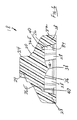
図1に最も良く示されるように、本発明の弁10は、入口ハウジング12と、出口ハウジング14とを備えており、好ましくは、これらは溶接又は接着などによりジョイント16で永久的に結合されている。入口ハウジング12及び出口ハウジング14は、それぞれ、管継手12Tおよび14Tを含む。なお、ハウジング12および14は、本発明の精神および範囲から逸脱することなく、ルアーロックフィッティングなどの他のタイプのフィッティングを含むことができることを理解されたい。例えば、入口ハウジング12および出口ハウジング14の一方又は両方には、バーブホースフィッティング、ルアーフィッティング又はロックルアーフィッティングなどを設けてもよい(上述した米国特許第7,296,782号及び米国特許第7,641,174号のドーム逆止弁の様々な実施形態を参照)。入口ハウジング12および出口ハウジング14は、更に、共に嵌合するように適切に構成された略ドーム状の大径構成12Dおよび14Dを含み、ジョイント16に締結される。
As best shown in FIG. 1, the
図2及び図3に示すように、弾性(エラストマー)のドーム状弁要素18が、入口ハウジング12および出口ハウジング14のドーム状の大径構成12Dと14Dとの間に取り付けられている。
As shown in FIGS. 2 and 3, an elastic (elastomer) dome-shaped
図4−7により良く示されるように、弁要素18は、一体形成された中央ステム22を有する略ドーム状構成20を備え、好ましくは円錐台形状であって、同心円上に配置され、入口ハウジング12内に延びている。一体形成された中央ステム22は、等間隔に配置された複数の放射状突起24(例えば、3つがそれぞれ120度に配置されて示されている)を有する星形構成を備えている。ステム22が円形の筒状に構成されている場合、ステム22がシリンジ又は他の装置などのルアーフィッティングの先端によって係合されると、その周囲に流体を流すことができる。本発明の精神および範囲から逸脱することなく、ステム22の他の構成を採用してもよく、例えば、上述した米国特許第7,296,782号および米国特許第7,641,174号のドーム状逆止弁に示されるスロット及びノッチなどのアクセス装置の先端部でのシーリングをなくすことができる。
As better shown in FIGS. 4-7, the
上述の米国特許第7,296,782号および米国特許第7,641,174号のドーム逆止弁とは異なり、本発明では、ドーム状弁要素18は、等間隔で配置された複数の切欠き26(6つが図示されている)を含む。切欠き26は、そこに流体を流すことができ、これにより、弁要素18が開かれたときに弁10を通って流れる流体の流量を増大させている。また、切欠き26は、ドーム状弁要素18の下に空気が閉じ込められる可能性を最小にしながら、流体を効率的に流している。略ドーム状構成の弁要素18は、更に、その周囲に延在する一体形成された環状スカート30を備える。
Unlike the dome check valves of US Pat. No. 7,296,782 and US Pat. No. 7,641,174 described above, in the present invention, the dome-shaped
複数の切欠き26は、等間隔に配置された複数の脚部28(6つが図示されている)を画定することに留意する。複数の脚部28は、環状スカート30に合流するように、略半径方向外向きに、且つ下方に延びている。脚部28の幅は、切欠き26の幅によって画定され、好ましくは、所望のクラッキング圧力を達成するのに十分な強度を有する脚部28を画定する(すなわち、脚部28を大きくするほど、弁要素18をクラック(開弁)するために必要なクラッキング圧力を増大させることになる)。
Note that the plurality of
図7と比較して図6に最も良く示されているように、脚部28のそれぞれは、入口から第1角度で外側に傾斜する外側側壁32と、入口から第1角度より大きい第2角度で外側に傾斜する内側側壁34と、を備えることにより、実質的に厚い構成を達成している。これと比較して、一体形成された環状スカート30は、実質的に薄い構成を含んでおり、脚部28を安定させ、それらを互いに対して略半径方向に保持している。スカート30の最下部の環状縁部は、安定性を向上させるため、厚さを増加させて内側に延びるリム30Rを含む。
As best shown in FIG. 6 compared to FIG. 7, each of the
図6及び図7は、更に、ドーム状弁要素18の下面の構成を示しており、下面の周りに環状に延在する略凹状部分(凹部)36を含み、逆さまの三次元双曲面(すなわち、単一のポールファブリックテントの曲面に類似する)の形状で外向きに延びる点38を画定する。凹部36は、上述した従来技術のドーム逆止弁で生じる可能性のある弁要素18の下に、空気が閉じ込められないようにするものである。図7に示すように、凹部36の周縁部36Eは、丸められており、切欠き26に入れられている。また、図6に示すように、周縁部36Eと脚部28との間にアンダーカット40を形成し、切欠き26を通る流体を効率的に流している。アンダーカット40は、リビングヒンジとして機能し、正確に制御された方法でクラッキングしている間に内向きにドーム状弁要素18を移動可能にするとともに、脚部28と周縁部36Eとの間の他の鋭角なコーナー周りでの流体を効率的に流している。
FIGS. 6 and 7 further show the configuration of the lower surface of the dome-shaped
図2及び図3と共に図8を参照すると、入口ハウジング12のドーム状大径構成12Dの内側は、環状弁座42を有する。環状弁座42は、弁要素18がハウジング12及び14内の静止位置にあるとき、弁要素18のドーム状構成20の上面と共にシールを形成する。出口ハウジング14のドーム状大径構成14Dの内側は、環状シート44を有する。弁要素18がハウジング12および14内の静止位置にあるとき、環状シート44には、環状スカート30の内側に延びるリム30Rが着座する。出口ハウジング14のドーム状大径構成14Dの内側は、複数のキャスタレーション46(4つが示されている)を有している。キャスタレーション46は、凹部36によって画定される双曲面の外形よりかなり小さい内径を有し、弁要素18がクラックされて開かれると、弁要素18が内部へ移動するのを制限する。脚部28の数とキャスタレーション46の数とが異なることが好ましい。
Referring to FIG. 8 together with FIGS. 2 and 3, the inside of the dome-shaped
作動中において、静止位置では、弁10を通る二方向の流体の流れは、脚部28とスカート30の弾性力によってシールされることでブロックされる。このシールは、環状弁座42と、弁要素18のドーム状構成20の上面との間に形成される。弁10は、入口ハウジング12の流体圧力によってか、又は脚部28及びスカート30の弾性力に対して弁要素18の一体形成された中央ステム22に、シリンジなどの物理的物体により力を加えることによって、開かれてもよい、即ち、「クラックされ」てもよい。弁要素18がクラックされて開かれると、入口ハウジング12からの流体の流れは、ステム22の周りを、弁要素18のドーム状構成20の外面を半径方向に横切り、切欠き26を通って、脚部28とキャスタレーション46を過ぎて、出口ハウジング14を介して流出する。重大なことは、弁要素18がクラック(開弁)されると、流体の実質的な流れが、弁10を通ることが可能となることである。クラッキング圧力がなくなると、入口ハウジング12内に流入する流体の圧力が小さくなることによってか、又は弁10をクラックした物体を取り除くことによって、脚部28とスカート30の固有の弾力性が働く。これにより、弁要素18のドーム状構成20は、入口ハウジング12の環状弁座42とのシール係合に戻る。好ましくは、それらの間に生じるシール力は、出口ハウジング14内に流体圧力がないときでさえも十分にシールすることができる。さらに、弁要素18のドーム状構成20は、大きな流体背圧が出口ハウジング14から出ても、シールされたままに保つことができる。さらに、ドーム状構成20と結合されたドーム状構成20の移動制限は、入口ハウジング12に非常に高い圧力がかかっても、弁要素18が変形しない(すなわち、吹き飛ばされない)ようにすることを保証している。
In operation, in the rest position, bidirectional fluid flow through the
本開示は、添付の特許請求の範囲に含まれるもの、および前述の説明のものを含む。本発明は、ある程度の詳細さをもって好ましい形態で記載されているが、本開示の好ましい形態は例としてのみなされたものであり、本発明の精神および範囲から逸脱することなく、詳細な構造、部品の組み合わせ及び配置において、多くの変更が可能であることが理解される。 The present disclosure includes that contained in the appended claims and the foregoing description. Although the invention has been described in a preferred form with some detail, the preferred form of the disclosure has been made by way of example only and without departing from the spirit and scope of the invention. It will be appreciated that many variations in the combinations and arrangements are possible.
以上、本発明について説明した。 The present invention has been described above.
Claims (11)
前記入口と前記出口との間に配置され、前記入口に対するシールを形成するドーム状の弾性弁要素、
を備え、
前記ドーム状の弾性弁要素は、流体を流すことが可能な複数の切欠きを有する、これにより、前記ドーム状の弾性弁要素がクラックして開かれたときに逆止弁を通って流れる流体の流量を増大させ、
前記ドーム状の弾性弁要素は、更に、その外周の周りに延びる一体形成された環状スカートを有し、
前記複数の切欠きは、前記環状スカートに合流するように、ほぼ半径方向外側に、且つ下方向に延びる等間隔の複数の脚部を画定し、
前記等間隔の複数の脚部の幅は、前記複数の切欠きの幅によって画定されることによって、前記等間隔の複数の脚部の強度がクラッキング圧力を実現し、
前記ドーム状の弾性弁要素の下面は、前記下面の周りを環状に延在する凹状部分を含み、前記凹状部分は、前記ドーム状の弾性弁要素の下に空気が閉じ込められないように、逆さまの三次元双曲面形状を有する外向きに延びる点を画定し、
前記ドーム状の弾性弁要素は、更に、中央ステムを有し、
前記出口は、ドーム状内部構成を有し、
前記入口の前記ドーム状内部構成は、環状弁座を有し、前記環状弁座は、前記ドーム状の弾性弁要素が前記ハウジング内の静止位置にあるときに前記ドーム状の弾性弁要素の上面とシールを形成し、
前記出口の前記ドーム状内部構成は、環状シートを有し、前記環状シートには、前記ドーム状の弾性弁要素が静止位置にあるときに前記環状スカートの内側に延びるリムが着座し、
前記出口の前記ドーム状内部構成は、複数のキャスタレーションを有し、前記複数のキャスタレーションは、前記凹状部分によって画定される前記三次元双曲面の外径よりも小さい内径を有し、前記ドーム状の弾性弁要素がクラックして開かれると前記ドーム状の弾性弁要素の内部への移動を制限する、逆止弁。 A housing having an inlet and an outlet having a dome-like internal configuration;
A domed elastic valve element disposed between the inlet and the outlet and forming a seal against the inlet;
With
The dome-shaped elastic valve element has a plurality of notches through which fluid can flow, so that the fluid flowing through the check valve when the dome-shaped elastic valve element is cracked and opened. Increase the flow rate of
The dome-shaped elastic valve element further has an integrally formed annular skirt extending around its outer periphery;
The plurality of notches define a plurality of equally spaced legs extending radially outwardly and downwardly to meet the annular skirt;
The widths of the equally spaced legs are defined by the widths of the notches so that the strength of the equally spaced legs provides cracking pressure,
The lower surface of the dome-shaped elastic valve element includes a concave portion extending annularly around the lower surface, and the concave portion is turned upside down so that air is not trapped under the dome-shaped elastic valve element. Defining an outwardly extending point having a three-dimensional hyperboloid shape of
The dome-shaped elastic valve element further has a central stem,
The outlet has a dome-like internal configuration;
The dome-shaped internal configuration of the inlet has an annular valve seat, the annular valve seat being an upper surface of the dome-shaped elastic valve element when the dome-shaped elastic valve element is in a stationary position within the housing. And form a seal,
The dome-like internal configuration of the outlet has an annular seat on which a rim that extends inside the annular skirt is seated when the dome-like elastic valve element is in a stationary position;
The dome-shaped internal configuration of the outlet has a plurality of castellations, the plurality of castellations having an inner diameter that is smaller than an outer diameter of the three-dimensional hyperboloid defined by the concave portion, and the dome A check valve that restricts the movement of the dome-shaped elastic valve element to the inside when the elastic valve element is cracked and opened.
Applications Claiming Priority (3)
| Application Number | Priority Date | Filing Date | Title |
|---|---|---|---|
| US201562151497P | 2015-04-23 | 2015-04-23 | |
| US62/151,497 | 2015-04-23 | ||
| PCT/US2016/029242 WO2016172721A1 (en) | 2015-04-23 | 2016-04-25 | High pressure dome check valve |
Publications (3)
| Publication Number | Publication Date |
|---|---|
| JP2018513950A JP2018513950A (en) | 2018-05-31 |
| JP2018513950A5 JP2018513950A5 (en) | 2019-05-09 |
| JP6609323B2 true JP6609323B2 (en) | 2019-11-20 |
Family
ID=57144295
Family Applications (1)
| Application Number | Title | Priority Date | Filing Date |
|---|---|---|---|
| JP2017555389A Active JP6609323B2 (en) | 2015-04-23 | 2016-04-25 | High pressure dome check valve |
Country Status (4)
| Country | Link |
|---|---|
| US (1) | US9976660B2 (en) |
| EP (1) | EP3289251B1 (en) |
| JP (1) | JP6609323B2 (en) |
| WO (1) | WO2016172721A1 (en) |
Families Citing this family (12)
| Publication number | Priority date | Publication date | Assignee | Title |
|---|---|---|---|---|
| US10441761B2 (en) | 2016-07-01 | 2019-10-15 | Boston Scientific Scimed, Inc. | Delivery devices and methods |
| CN110382027B (en) | 2017-01-10 | 2022-10-14 | 波士顿科学国际有限公司 | Device and method for delivering a powdered medicament |
| EP4218844A1 (en) | 2018-01-12 | 2023-08-02 | Boston Scientific Scimed, Inc. | Powder for achieving hemostasis |
| US11766546B2 (en) | 2018-01-31 | 2023-09-26 | Boston Scientific Scimed, Inc. | Apparatuses and methods for delivering powdered agents |
| US11001490B2 (en) * | 2018-04-10 | 2021-05-11 | Bericap Holding Gmbh | Extraction system from a closed loop system |
| US11229467B2 (en) * | 2018-04-11 | 2022-01-25 | Zimmer Gmbh | Valve for prefilled bone cement mixing system |
| EP4176912A3 (en) | 2018-10-02 | 2023-08-02 | Boston Scientific Scimed, Inc. | Devices for fluidization and delivering a powdered agent |
| US11642281B2 (en) | 2018-10-02 | 2023-05-09 | Boston Scientific Scimed, Inc. | Endoscopic medical device for dispensing materials and method of use |
| EP3714919A1 (en) * | 2019-03-29 | 2020-09-30 | Fresenius Medical Care Deutschland GmbH | Reinfusion tube system, package and methods |
| EP4017338B1 (en) | 2019-12-03 | 2024-01-31 | Boston Scientific Scimed, Inc. | Medical devices for agent delivery |
| EP4017377A1 (en) | 2019-12-03 | 2022-06-29 | Boston Scientific Scimed, Inc. | Agent administering medical device |
| WO2023192865A2 (en) * | 2022-03-29 | 2023-10-05 | Equilibar, Llc | Check valve and compact pump system |
Family Cites Families (19)
| Publication number | Priority date | Publication date | Assignee | Title |
|---|---|---|---|---|
| US3831629A (en) | 1972-01-24 | 1974-08-27 | Halkey Roberts Corp | Check valve |
| US4369812A (en) | 1981-02-18 | 1983-01-25 | Nypro Inc. | Control of fluid flow using precisely positioned disc |
| US4499916A (en) | 1983-01-31 | 1985-02-19 | Allied Corporation | Vacuum check valve |
| US4749003A (en) * | 1987-01-22 | 1988-06-07 | Filtertek, Inc. | Center flow check valve |
| US5349984A (en) | 1993-01-25 | 1994-09-27 | Halkey-Roberts Corporation | Check valve |
| US5509433A (en) * | 1993-10-13 | 1996-04-23 | Paradis; Joseph R. | Control of fluid flow |
| US5529278A (en) | 1993-11-19 | 1996-06-25 | Novoste Corporation | Fluid access and flow control valve |
| US5573516A (en) | 1995-09-18 | 1996-11-12 | Medical Connexions, Inc. | Needleless connector |
| DE19723648C1 (en) * | 1997-06-05 | 1998-08-27 | Disetronic Licensing Ag | Controlled infusion equipment with leak and reverse flow prevention used e.g. in insulin therapy |
| US5899624A (en) * | 1997-09-08 | 1999-05-04 | Thompson; Edwin | Fluid dispensing valve |
| US5909747A (en) * | 1998-04-03 | 1999-06-08 | American Meter Company | Radial flow diaphragm valve |
| US5992462A (en) | 1998-10-28 | 1999-11-30 | Vernay Laboratories, Inc. | Disc type check valve |
| IT1311347B1 (en) | 1999-11-12 | 2002-03-12 | Borla Ind | CHECK VALVE FOR MEDICAL INFUSION LINES AND SIMILAR. |
| ITMI20020819A1 (en) * | 2002-04-18 | 2003-10-20 | Gambro Lundia Ab | CONNECTION ELEMENT AND CONNECTION DEVICE FOR MEDICAL USE PIPES |
| US7296782B2 (en) | 2004-10-01 | 2007-11-20 | Halkey-Roberts Corporation | Dome check valve |
| WO2009144599A1 (en) * | 2008-04-14 | 2009-12-03 | Elcam Medical A.C.S. Ltd | Luer tip activated flow control device |
| AU2012271986A1 (en) * | 2011-06-22 | 2013-04-04 | Gambro Lundia Ab | Valve automatically opening on connection, and applications therefor |
| US9156569B2 (en) * | 2011-12-21 | 2015-10-13 | Berry Plastics Corporation | Pediatric dosing dispenser |
| EP2809385A4 (en) * | 2012-02-01 | 2015-10-28 | Hospi Corp | Valved enteral administration assembly |
-
2016
- 2016-04-25 US US15/138,015 patent/US9976660B2/en active Active
- 2016-04-25 EP EP16784101.4A patent/EP3289251B1/en active Active
- 2016-04-25 WO PCT/US2016/029242 patent/WO2016172721A1/en active Application Filing
- 2016-04-25 JP JP2017555389A patent/JP6609323B2/en active Active
Also Published As
| Publication number | Publication date |
|---|---|
| EP3289251A4 (en) | 2018-12-12 |
| US9976660B2 (en) | 2018-05-22 |
| JP2018513950A (en) | 2018-05-31 |
| WO2016172721A1 (en) | 2016-10-27 |
| EP3289251A1 (en) | 2018-03-07 |
| US20160312910A1 (en) | 2016-10-27 |
| EP3289251B1 (en) | 2020-02-26 |
Similar Documents
| Publication | Publication Date | Title |
|---|---|---|
| JP6609323B2 (en) | High pressure dome check valve | |
| AU2005291926B2 (en) | Dome check valve | |
| US6068011A (en) | Control of fluid flow | |
| KR102110129B1 (en) | Cap | |
| US5462255A (en) | Automatic fluid control valve | |
| US9861804B2 (en) | Compressible needleless valve assembly | |
| US9510689B2 (en) | Valve, self-inflating bladder assembly, cushion assembly and method for operating the same | |
| EP3359243B1 (en) | Check valve assembly | |
| US9651161B2 (en) | Check valve, especially for medical applications | |
| US20140014213A1 (en) | Applicator Assembly with Integral Check-Valve | |
| US10408372B2 (en) | Fluid-connecting element | |
| JP2011172615A (en) | Medical connector | |
| JP5714860B2 (en) | Condensate trap valve element and condensate trap | |
| JP3829109B2 (en) | Valve device | |
| AU2012200810B2 (en) | Dome Check Valve | |
| EP3366167A1 (en) | Lip activated closure for a drinking vessel | |
| CN214366677U (en) | Valve structure and oil-well pump | |
| WO2020007973A1 (en) | Fluid system | |
| JP2012223278A (en) | Medical connector | |
| JP2009119210A (en) | Mixed injection tube |
Legal Events
| Date | Code | Title | Description |
|---|---|---|---|
| A521 | Request for written amendment filed |
Free format text: JAPANESE INTERMEDIATE CODE: A523 Effective date: 20190328 |
|
| A621 | Written request for application examination |
Free format text: JAPANESE INTERMEDIATE CODE: A621 Effective date: 20190328 |
|
| A871 | Explanation of circumstances concerning accelerated examination |
Free format text: JAPANESE INTERMEDIATE CODE: A871 Effective date: 20190328 |
|
| A975 | Report on accelerated examination |
Free format text: JAPANESE INTERMEDIATE CODE: A971005 Effective date: 20190402 |
|
| A131 | Notification of reasons for refusal |
Free format text: JAPANESE INTERMEDIATE CODE: A131 Effective date: 20190514 |
|
| A521 | Request for written amendment filed |
Free format text: JAPANESE INTERMEDIATE CODE: A523 Effective date: 20190813 |
|
| TRDD | Decision of grant or rejection written | ||
| A01 | Written decision to grant a patent or to grant a registration (utility model) |
Free format text: JAPANESE INTERMEDIATE CODE: A01 Effective date: 20191001 |
|
| A61 | First payment of annual fees (during grant procedure) |
Free format text: JAPANESE INTERMEDIATE CODE: A61 Effective date: 20191025 |
|
| R150 | Certificate of patent or registration of utility model |
Ref document number: 6609323 Country of ref document: JP Free format text: JAPANESE INTERMEDIATE CODE: R150 |
|
| R250 | Receipt of annual fees |
Free format text: JAPANESE INTERMEDIATE CODE: R250 |
|
| R250 | Receipt of annual fees |
Free format text: JAPANESE INTERMEDIATE CODE: R250 |